Proxim Wireless S58-S60 Tsunami Multipoint Unlicensed Radio Transceiver User Manual Backing down from TNG CCI 2
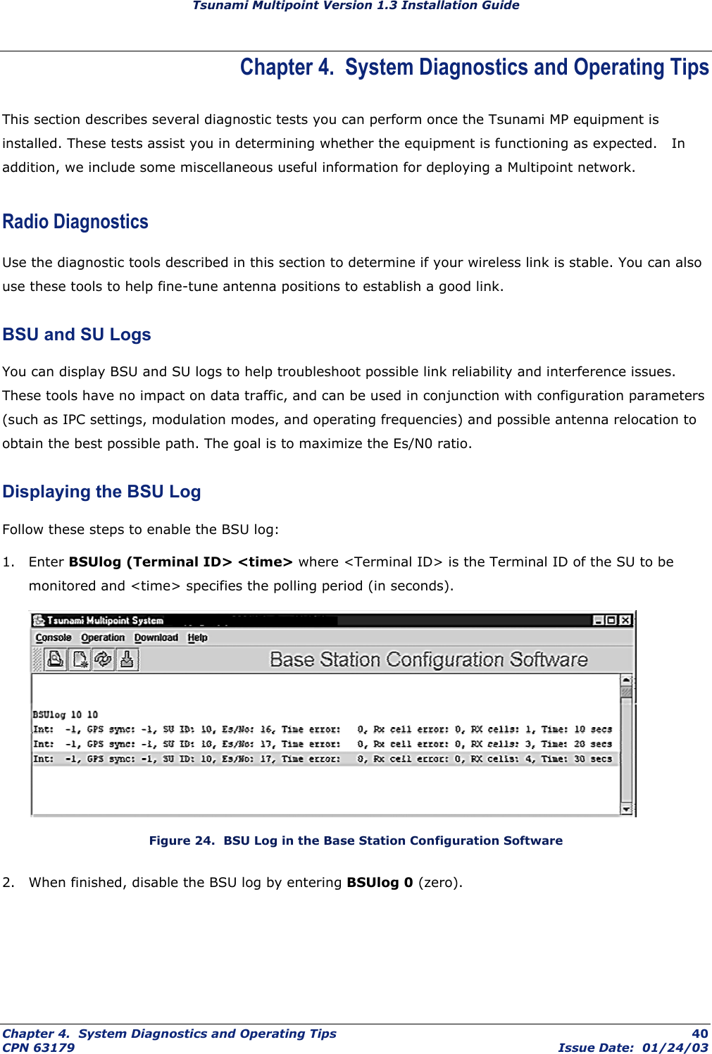
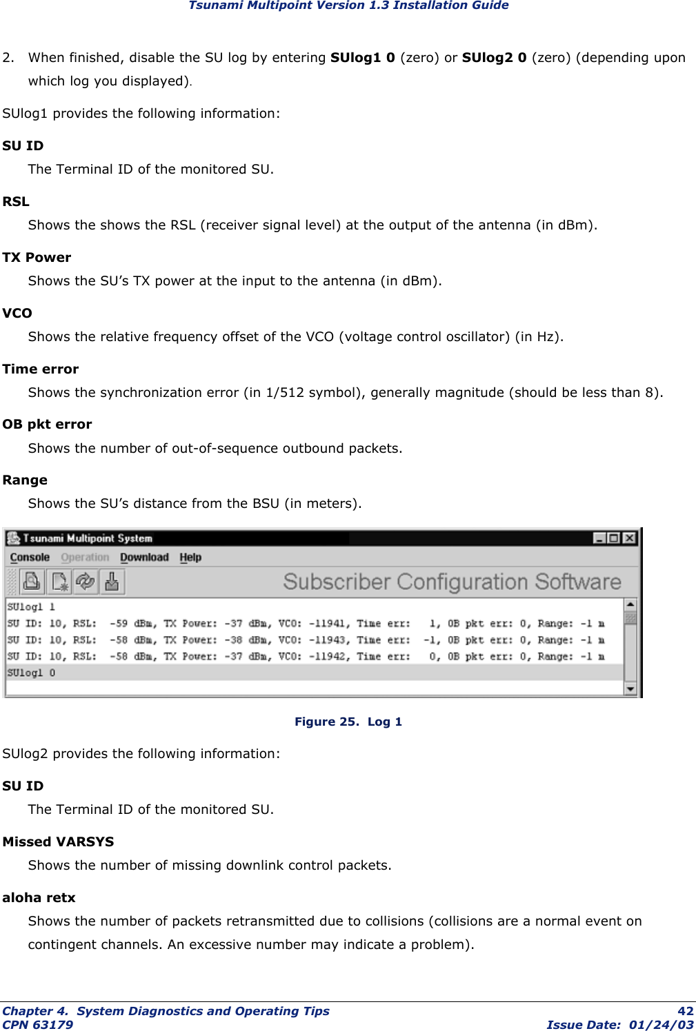
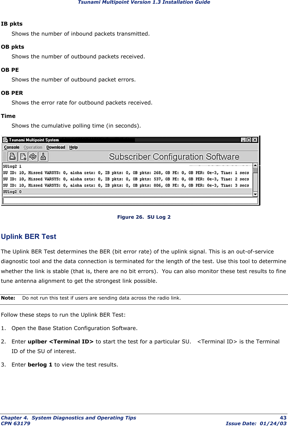
Proxim Wireless Corporation Tsunami Multipoint Unlicensed Radio Transceiver Backing down from TNG CCI 2
Contents
- 1. Antenna Manual
- 2. Users Manual Part 2
- 3. Users Manual Part 1
- 4. Users Manual Part 1 cont
Users Manual Part 2
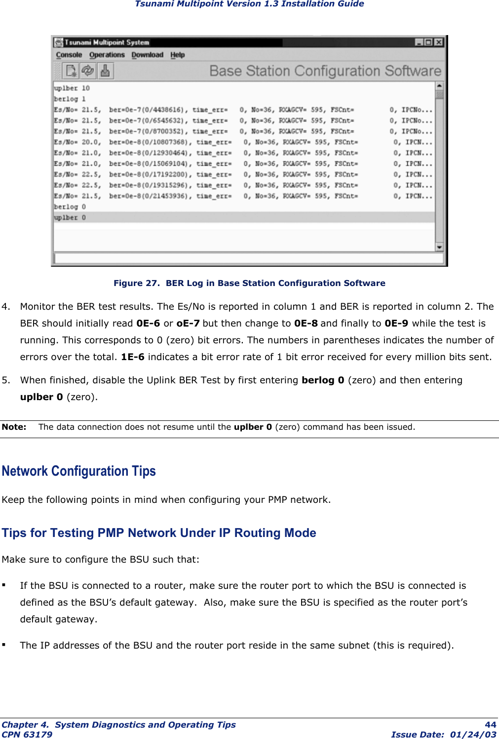
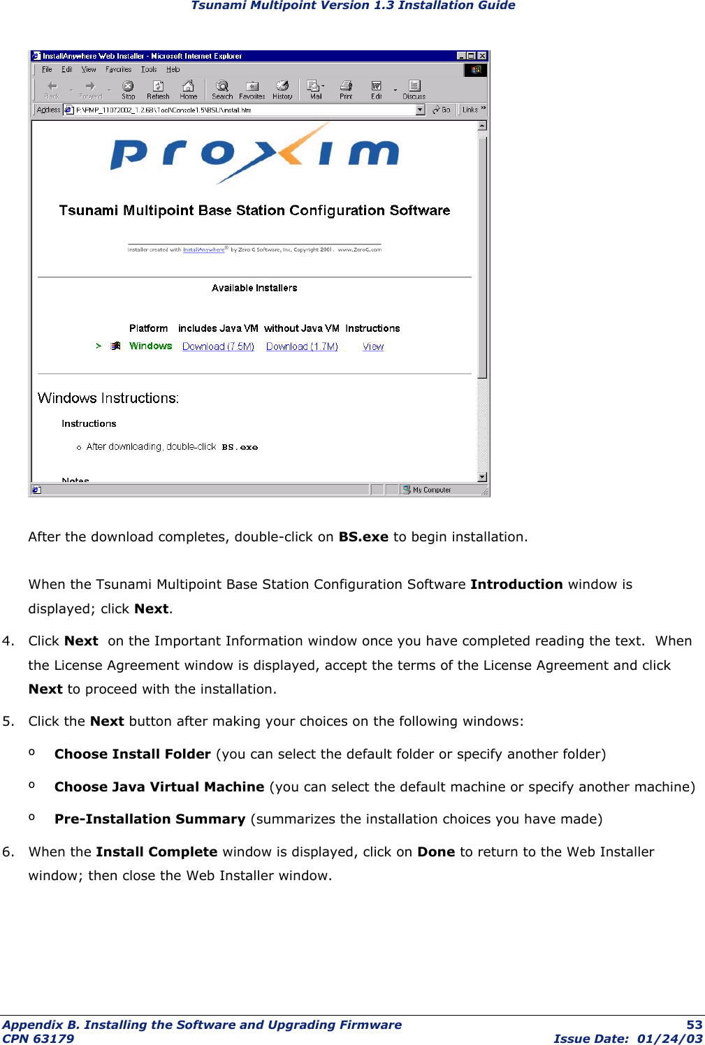
![Tsunami Multipoint Version 1.3 Installation Guide Password Protection Tsunami Multipoint provides two levels of password protection: ▪ user level – lets the user display the system’s current status only. ▪ admin level – lets the user display the system’s status and change its configuration. The default password is “null.” Password protection for either password level (user or admin) can be turned on and off. By default, password protection is turned off. Passwords can be from 1 to 16 characters; any combination of alphanumeric characters is allowed, except for these special characters: " , . ’ ‘ ^ { } | \ / ; : ] [ ( ) If you forget your password, contact Proxim’s Customer Service department to obtain a new one. See “Appendix F. Technical Support and Training” on page 76 for Proxim’s contact information. Specifying a User-Level Password To define the user-level password, from the BSU console enter: setpw user<oldpw><newpw><newpw> where: <oldpw> = the old password (the default password is “null”) <newpw> = the new password After defining the new user-level password, enter logout. Log in with the new password (see Logging In on page 47 for information). Specifying an Admin-Level Password To define the admin-level password, from the BSU console, enter: setpw admin<oldpw><newpw><newpw> where: <oldpw> = the old password (the default password is “null”) <newpw> = the new password After defining the new admin-level password, enter logout. Log in with the new password. Note: If you specify either level of password without specifying a password for the other level, when you log out or restart the BSU, the system comes up in password-protected mode. Log in and enter the password you specified. For example, if you specify “admin” for the admin-level password and then log out or restart the BSU, enter login admin to access the system. This allows access to the admin-level. Chapter 4. System Diagnostics and Operating Tips 46 CPN 63179 Issue Date: 01/24/03](https://usermanual.wiki/Proxim-Wireless/S58-S60.Users-Manual-Part-2/User-Guide-392343-Page-7.png)
![Tsunami Multipoint Version 1.3 Installation Guide Remote Over-the-Air Download to SUs You can upgrade your SUs to Version 1.3 from the Base Station Configuration Software Console of the BSU. Normally, all SUs in the network are upgraded at the same time. However, if one or more SUs fail to receive the download code correctly, the upgrade is aborted and a second attempt must be made. SUs that have been upgraded successfully ignore reprogramming of the same codes. To download remotely to SUs: 1. From the BSU 1.4 or 1.5 Console, confirm that SUs have established a link with the BSU by issuing a dspActiveSU command. Make note of the SUs in the network. 2. Select the Download menu. 3. Select Remote Firmware; a Download — File Selection window is displayed. 4. From the Look In search field, select the binary file to be downloaded (PMP_SU_release1-3.mot) from the appropriate directory. The BSU Console automatically processes the selected binary codes and, once finished, displays an output of “Elapsed [time]” in seconds. 5. Let the SUs re-enter the network. It usually takes no more than five minutes for the SUs to enter the network from the start of the download. The following messages are displayed at the BSU Console for each SU as it enters the network: º 118 Received NetEntry Request from Eth<SUs Ethernet address> º 119 NetEntry completed: Assigned terminal ID <ID#>, IP<SUs IP address>, and VLAN ID <SU VLAN ID#> in VLAN mode. 6. Issue dspActiveSU to verify that the SUs have entered the network successfully. If an SU fails to enter the network, use the local download procedure in the following section. º If the SU was correctly upgraded, the display reads ver 20021300. º If the SU failed to upgrade and the link was restored, the display most likely reads ver 200212B0. 7. If any SU that re-entered the network failed to upgrade to Version 1.3, repeat steps 2 through 6, or upgrade the failing SUs using the “Local Download to SUs” method. Local Download to SUs You can use this method to upgrade SUs that have not been deployed or have failed to successfully download using the remote over-the-air procedure. Using this procedure, individual SUs are upgraded through their Ethernet/Power cable. This procedure requires the Tsunami Multipoint Base Station Configuration Software application be loaded on the PC attached to the SU (SU 1.,4 or 1.5 Console). The window label appears as Tsunami Multipoint Subscriber Configuration Software. Appendix B. Installing the Software and Upgrading Firmware 55 CPN 63179 Issue Date: 01/24/03](https://usermanual.wiki/Proxim-Wireless/S58-S60.Users-Manual-Part-2/User-Guide-392343-Page-16.png)