Proxim Wireless S58-S60 Tsunami Multipoint Unlicensed Radio Transceiver User Manual Backing down from TNG CCI 2
Proxim Wireless Corporation Tsunami Multipoint Unlicensed Radio Transceiver Backing down from TNG CCI 2
Contents
Antenna Manual

Connecting External Antennas
TSUNAMI MULTIPOINT
CPN required
Issue Date: 03/05/2003
Copyright and Service Marks
Copyright © 2002 by Proxim Corporation. All rights reserved. No part of this manual may be reproduced
without prior written permission from Proxim Corporation.
The information contained in this manual is subject to change without notice. Proxim Corporation shall not
be liable for errors contained herein or for incidental or consequential damages in connection with the
furnishing, performance, or use of this manual or equipment supplied with this manual. Proxim Corporation
makes no warranty of any kind with regard to this manual or any equipment supplied with this manual,
including, but not limited to, the implied warranties of merchantability and fitness for a particular purpose.
Tsunami™ is a registered product of Proxim Corporation.
Windows is a registered product of Microsoft Inc.
Other names are trademarks of their owners.
Y2K (Year 2000 Issue): All software supplied by and for Proxim Corporation products adhere to the four-
(4) digit year nomenclature as required for Year 2000 compliance.

Contents
CONNECTING EXTERNAL ANTENNAS TO THE BSU AND SU ................................................... 4
Planning for Antenna Installation ....................................................................................... 4
Reviewing the Installation Process ..................................................................................... 6
1. Test radios back-to-back and configure.................................................................... 6
2. Mount antennas ................................................................................................... 6
3. Run transmission line route and egress, including lightning arrestors ........................... 6
4. Connect radios to antennas and power, including grounding ....................................... 7
5. Align antennas ..................................................................................................... 7
Installing the Units ......................................................................................................... 78
9
9
11
Establishing Connections .................................................................................................. 8
Antenna Connection ................................................................................................... 8
Antenna Cabling Guidelines for 5.8 GHz Units................................................................ 8
BSU/SU RF Connections ............................................................................................. 8
BSU/SU Power Connections ........................................................................................10
Installing and Adjusting the Antenna .................................................................................10
Antenna Installation ..................................................................................................10
Alignment Guidelines............................................................................................. 10
Establishing a Connection Between the Units ......................................................................12
Connecting External Antennas to the BSU and SU 3
CPN 000000 Draft Date: 02/25/03

Connecting External Antennas to the BSU and SU
Standard Tsunami Multipoint outdoor unit
models include integral antennas. However, SU
models 40100-xxxC and BSU models 40400-xxC
replace the integral antennas with a type-N
female connector, letting you purchase and use
antennas better suited for your particular
application, if so desired.
Planning for Antenna Installation
In general, the larger the antenna used with the
radio, the better the link performs. Larger
antennas have narrower beamwidth and higher
gain, which yield better link performance (higher
fade margin, better availability) and improve
immunity to interference. However, larger
antennas are more costly to purchase and install
than smaller antennas and, in some cases,
require special installation equipment and more
robust mounting structures (due to increased
weight and wind loading).
Base stations, however, require wide
beamwidths in azimuth so that a large segment
of subscribers can be accessed spatially.
Antennas are available to allow sectors ranging
from 30° to 360°. Of course, the larger the
sector, the less antenna gain for longer
transmission distance and interference
immunity.
Finally, antenna polarization must be considered.
The BSU and SU integral antennas use left-hand
circular polarization (LHCP). External antennas
with either linear or circular polarization can be
considered. Use the following guidelines to
assist in your planning.
1. The polarization of the BSU and SU antennas
should be of the same type. For a given
polarization, the same polarity (vertical ir
horizontal) must be used at each end of the
link.
2. Linear and circular polarization can be used
at opposite ends of the link; however, this
results in a 3 dB loss in signal strength.
3. Integral antenna units and external antenna
units can be used in the same sector.
4. Only LHCP antennas can be used with SUs
connecting to a BSU with Active Interference
Rejection (A.I.R.).
Note: The A.I.R. BSU is compatible only with LHCP
signals from SUs. SUs must use LHCP
antennas; either the integral antenna or an
LHCP external antenna.
You should consider all of these factors when
selecting an antenna. This advanced planning
also yields the transmission line requirements.
4 Connecting External Antennas to the BSU and SU
Draft Date: 02/25/03 CPN 000000
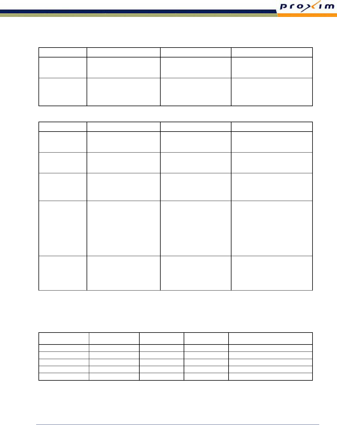
The following tables list antenna types, performance, and manufacturers.
BSU Antenna Information
Antenna Type Manufacturer Model Number Mid-Band Gain (dBi)
Omni Telex
MTI
MTI
5830AN
MT-482009/N
MT-483003/N
7.5
9
12
Flat Panel, Sector European Antennas
European Antennas
Radio Waves
Radio Waves
SA16-30-58H/736
SA17-55V/450
SEC-5V/H-90-17
SEC-5V/H-60-18
16
17
17
18
SU Antenna Information
Antenna Type Manufacturer Model Number Mid-Band Gain (dBi)
Omni Telex
MTI
MTI
5830AN
MT-482009/N
MT-483003/N
7.5
9
12
1-foot Flat Panel Gabriel
RFS
Andrew
DFPD1-52
MA0528-23AN
FPA5250D12-N
23.5
23.0
23.6
2-foot Flat Panel Gabriel
RFS
MTI
Andrew
DFPD2-52
MA0528-28AN
MT-20004
FPA5250D24-N
28.0
28.0
28.0
28.2
2-foot Parabolic RFS
Gabriel
Gabriel
Gabriel
YDI
Radio Waves
Radio Waves
Andrew
SPF2-52A
HSSP2-52
SSD2-52A
SSP2-52B
A5.8-2’-RW
SP2-5.2/SPD2-5.2
SP2-5.8/SPD2-5.8
P2F-52/PX2F-52
27.9
28.1
28.4
28.5
28.3
28.0
28.5
29.4
3-foot Parabolic Radio Waves
Radio Waves
RFS
YDI
Andrew
SP3-5.2/SPD3-5.2
SP3-5.8/ SPD3-5.8
SPF3-52A
A5.8-3’-RW
P3F-52/PX3F-52
31.2
31.4
31.4
31.4
33.4
Recommended transmission lines are listed in the following table.
Transmission Line
Type Manufacturer Model Number Loss/100 ft, dB Notes
½-inch foam coax Andrew LDF 4-50 6.1 Add –0.25 dB per connector
5/8-inch foam coax Andrew LDF 4.5-50 4.7 Add –0.25 dB per connector
Waveguide Andrew EW-52 1.2 Does not include transitions
½-inch foam coax Times Microwave LMR-600 7.3 Add –0.25 dB per connector
5/8-inch foam coax Times Microwave LMR-900 4.9 Add –0.25 dB per connector
Connecting External Antennas to the BSU and SU 5
CPN 000000 Draft Date: 02/25/03

Prior to installation, determine the specific
antenna location and type of mounting. The
transmission line should be kept as short as
possible so, when line-of-sight placement of
antennas allow flexibility, it is always desirable
to locate the equipment closer to the antenna.
Within the USA and Canada, antennas other
than those illustrated in these tables can be
used with this radio, but must be of the same
type (flat panel or solid parabolic), dimensions,
and gain as those listed in the table. Antennas
with gain less than 7.5 dBi are not approved for
use within the USA or Canada. Consult
governmental regulations or Proxim Corporation
for applications outside of the USA or Canada.
For further information regarding antenna
installation and adjustment, see “Installing and
Adjusting the Antenna” later in this section.
Note: Max BSU Tx (dBm) is the lesser
of 17 dBm and 36 - G + L
G is the antenna gain and L is the
transmission line loss.
Reviewing the Installation Process
The following is an overview of the installation
process to assist you in your planning activities.
1. Test Radios Back-to-Back and
Configure
▪ Use at least 60 dB and no more than 80 dB
attenuation and a short low-loss RF
transmission line to connect the two radios.
▪ Apply power.
▪ Verify configuration settings (through the
BSU Console) for proper configurations.
▪ Verify that the SU enters the network.
▪ Connect to services, if possible, to verify
network connection and configurations.
2. Mount Antennas
▪ Antenna height can be critical for path
clearance and line of sight.
▪ Ensure that antennas will not be blocked by
people.
▪ Antenna structure must be secure for wind
load and whatever climbing may be
necessary.
3. Run Transmission Line Route and
Egress, including Lightning Arrestors
▪ Use proper transmission line.
▪ Proper termination is critical, especially at
5.8 GHz.
▪ Be careful with the bend radius and never
kink the transmission line.
▪ Secure transmission line to structures; be
careful not to crush.
▪ A direct connection to the antenna feed is
ideal (if required, you can use a flexible
jumper at the antenna, a properly specified
90-degree connector/adaptor, or both).
▪ Weatherproof all outdoor connections when
completed with installation.
▪ If the transmission line is longer than three
meters, a lightning arrester located near the
RF Unit is recommended. If the RF Unit is
6 Connecting External Antennas to the BSU and SU
Draft Date: 02/25/03 CPN 000000

located indoors, locate the lightning arrestor
at the building egress point.
▪ All lightning arrestors and transmission line
must be properly grounded.
4. Connect Radios to Antennas and
Power, including Grounding
▪ Connect to RF transmission line from
antenna directly or using flexible jumper, if
necessary.
▪ Do not use 90° adapters unless rated at
operating frequency.
▪ Connect CAT5 cable from power adapter to
BSU/SU.
▪ Test power voltages and pinouts before
connecting power to BSU/SU.
5. Align Antennas
▪ Rough align antenna azimuth and elevation
based upon path planning (using compass
bearing or milestone sighting, telescopic
sight, binoculars, and so on).
▪ Use the audio indicator to align the SU
antenna, or the received signal quality
indicator display of the SU Utility software to
peak antennas.
▪ Adjust alignment of one antenna at a time,
one plane (azimuth versus elevation) at a
time.
▪ Adjust each end multiple times until
predicted RSL is achieved.
Installing the Units
Follow the instructions in “Chapter 2. Deploying
the Base Station Unit” in the Tsunami Multipoint
Installation Manual to unpack, mount, and
configure the BSU. Chapter 2 includes these
topics:
▪ Deploying the Base Station Unit
º Unpacking the System
º Mounting the Base Station Unit
º Installing the GPS Antenna
º Installing BSU Configuration Software
• Operating in a Test Environment
• Indoor Deployment
• Configuring the Base Station
• Adding Subscribers to the BSU
Database
• Configuring the System for Multi-
Sector Mode
• Testing the GPS Receiver
Follow the instructions in “Chapter 3. Deploying
the Subscriber Unit” in the Tsunami Multipoint
Installation Manual to mount and configure the
SU. Chapter 3 includes these topics:
▪ Deploying the Subscriber Unit
º Mounting the Subscriber Unit
º Installing the Subscriber Utility Software
º Aiming the SU
º Displaying Link Status Information
º Confirming Network Activity
Connecting External Antennas to the BSU and SU 7
CPN 000000 Draft Date: 02/25/03
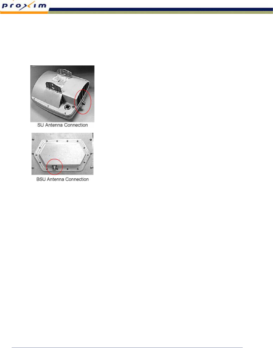
Establishing Connections
Antenna Connection
The BSU and SU radios are equipped with an N-
type female connector at the antenna port.
You can use a short length jumper cable (such
as ¼- to ½-inch coax or pigtail of approximately
6 feet in length) fitted with two N-type male
connectors to connect the antenna port to the
antenna (if the unit is located near the antenna)
or to the primary transmission line (if the unit is
mounted remotely from the antenna).
A low-loss 50-ohm cable is recommended for the
antenna transmission line between the BSU/SU
and the antenna (such as Andrew LDF4-50 or
Times LMR-600 1/2-inch coaxial cable, an
Andrew LDF4.5-50 or Times LMR-900 5/8-inch
coaxial cable, or an EW-52 waveguide).
The return loss presented by the transmission
line at the BSU/SU interface should be as high
as possible (20 dB minimum recommended).
The length of the antenna transmission line
should be kept as short as possible to minimize
loss.
Antenna Cabling Guidelines for 5.8 GHz
Units
▪ Coaxial cables of 7/8-inch or larger diameter
can exhibit moding at 5.8 GHz and are never
recommended. Also, some small diameter
cable types, such as RG-8, have high loss or
poor VSWR at these frequencies. If small
diameter cables are required, be certain to
keep the lengths of these cables as short as
possible.
▪ For wave guide transmission line at 5.8 GHz,
EW-52 wave guide is recommended. EW-63
also works, but exhibits more loss.
▪ Do not use right-angle N-type connectors
with the BSU/SU radios operating at 5.8 GHz
unless the connector has been specifically
rated and tested up to 5850 MHz. Unless
specifically designed for these frequencies,
these connectors can present high loss at
these frequencies.
▪ Do not use low quality jumper cables with
the radios.
▪ Always precisely follow manufacturer’s
recommended procedures and tools for
termination.
BSU/SU RF Connections
Prepare the RF transmission line feeder cable as
follows:
1. Cut the cable to the approximate length
(allowing some excess).
2. Install the appropriate connector on the
antenna or BSU/SU end: Place tape or a
covering over the connector end so that
debris cannot harm the connector.
8 Connecting External Antennas to the BSU and SU
Draft Date: 02/25/03 CPN 000000
3. Pull the transmission line through the cable
ducts, trays, or conduit (as required) to the
antenna, while being careful not to kink or
damage the transmission line in any way.
Note: RF transmission line must never be bent,
twisted, or deformed in any way.
Pay close attention to the transmission line
specifications for bend radius when installing.
4. Support the transmission line in a tray on
horizontal runs and by hangers on vertical
runs. Space hangers according to the
manufacturer instructions (typically every
five feet under conditions of no ice and not
greater than 85 mph winds).
5. Ground the transmission line using the
manufacturer grounding kit. Grounding kits
attach to the outer copper conductor. Install
grounds at the antenna, at the bottom of the
antenna structure (if applicable), and where
the transmission line enters the building. Be
sure to ground long transmission line runs
every 100 feet.
6. Lightning suppression (such as Polyphaser
LSX) is required at the interconnection cable
junction as close as possible to the BSU/SU
when the cable is longer than 3 meters.
There should always be a lightning
protection device at the egress point for
whatever cables egress the building or
enclosure. Lightning arrestors must be
properly grounded to operate.
7. After installation, terminate the transmission
line with an N-type male connector or
adapter attached at the equipment end. For
wave guide, this typically requires a CPR-to-
N adapter.
Be sure to use manufacturer-specified
connectors and termination tools, and follow
termination instructions precisely. Improper
transmission line terminations can cause
excess losses and reflections that can lead to
many problems with the system.
8. Prior to operation, check the electrical
integrity of the transmission line, including
all connectors, with a simple DC check
between the center conductor and outer
conductor (this is neither possible, nor
required for wave guide). The transmission
line ideally should be connected directly to
the antenna at one end and to the BSU/SU
antenna port at the other end (through the
RF Lightning arrestor). However, short
pigtail jumper cables may be required to
avoid sharp bends in the primary
transmission line to limit stress on either
connection.
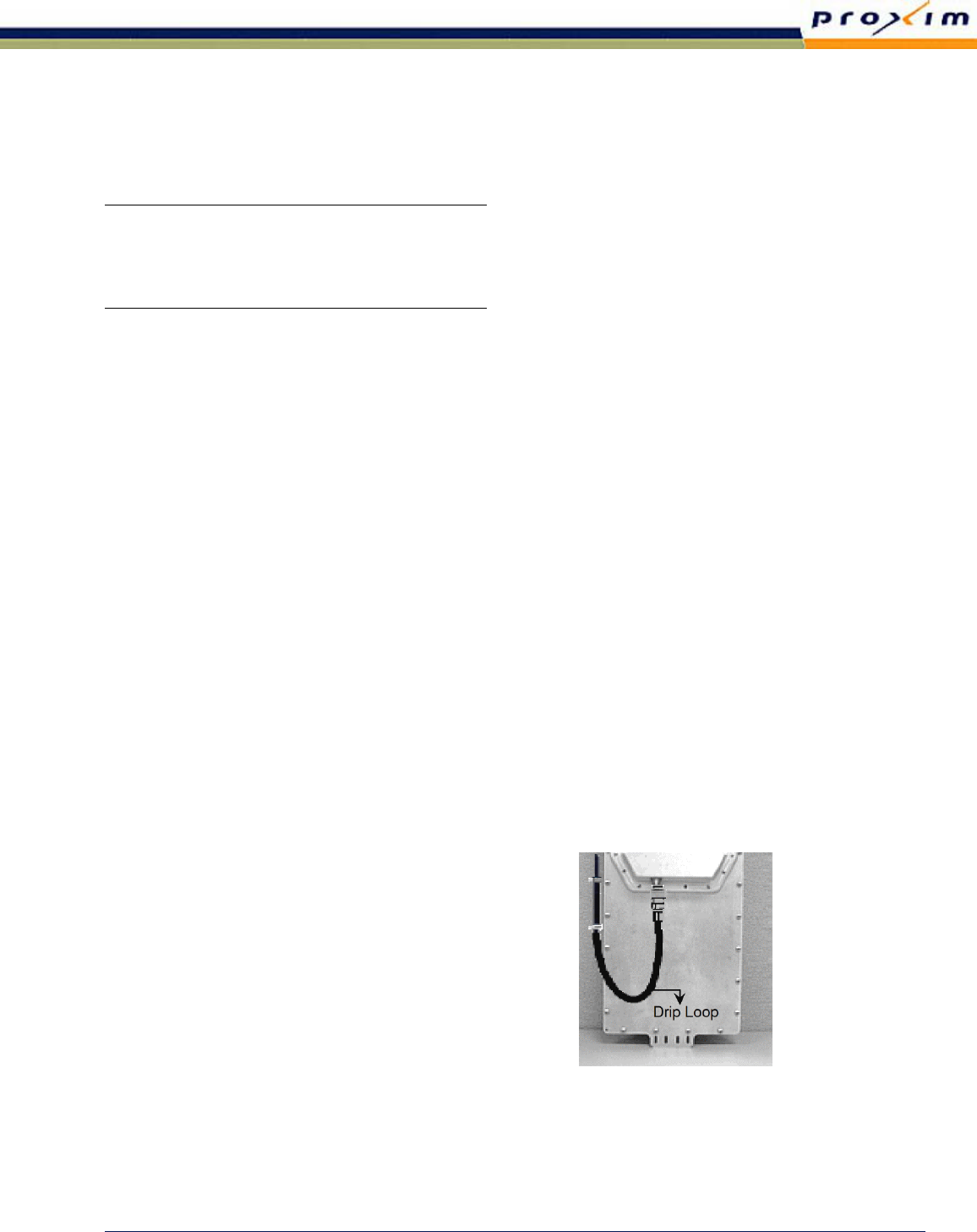
9. Connect the transmission line to the RF
connector on the BSU or SU. Create a drip
loop in the cable as shown in the figure
below, and tie the cable to the mast or pole
to remove any stress on the RF connector.
The drip loop allows any moisture on the
wires from rain or condensation to drip off.
[temporary
photo]
Connecting External Antennas to the BSU and SU 9
CPN 000000 Draft Date: 02/25/03

BSU/SU Power Connections
Refer to “Appendix D. Constructing Power and
Ethernet Cables” in the Tsunami Multipoint
Installation Manual for instructions.
Installing and Adjusting the Antenna
The installation information discussed in this
section is generic. For installation procedures
specific to the antenna you are installing, refer
to the antenna manufacturer’s documentation.
Antenna Installation
WARNING
(FCC requirement for implementation in the USA)
Antennas used for the transmitter must be fix-
mounted on outdoor permanent structures with
a separation distance of at least 2 meters from
all persons during normal operation. Antennas
must be professionally installed. Installers must
be provided with antenna installation instruct-
tions and transmitter operating conditions,
including antenna co-location requirements of
CFR47 Part 1.1307(b)(3), for satisfying RF
exposure compliance.
Antenna installation consists of permanently
mounting the antenna to the mast, pole, or
tower and then attaching the RF Unit (BSU or
SU) to it.
The antenna and RF Unit must be mounted
outdoors on a tower, building roof, or other
location that provides line-of-sight path
clearance to the far-end location. In some
cases, the antenna can be mounted indoors,
behind a window; however, RF attenuation
through windows can vary greatly, depending
upon the glass and any coatings that might be
present, plus the precise location and angle of
the antenna relative to the window.
In cases of indoor installations, ensure that the
antenna location is restricted and bear in mind
the RF exposure requirements of the warning
statement above.
Antennas should be:
▪ Ordered with the suitable mounting kit
specific to the site requirements.
▪ Very rigidly mounted, with adequate room
for azimuth and elevation adjustment from
the rear.
The antenna polarization must be the same at
both ends of the link, either vertical or
horizontal.
In general, antenna mountings require a support
pipe to which upper and lower support brackets
are attached with U-bolts. The antenna and
optional elevation and azimuth adjustment rods
are then mounted onto the support brackets.
The entire structure must be adequately
grounded for lightning protection. The antenna
system must always be installed according to
the manufacturer's instructions.
Alignment Guidelines
When aligning antennas, if the SU is located
indoors or distant from the antenna location,
you may want to use a cellular telephone or
two-way radio for relaying signal strength
information from the SU Utility software to the
antenna alignment location.
Similarly, a cellular telephone or two-way radio
can be used to relay received signal strength
information at the SU to the BSU alignment end.
10 Connecting External Antennas to the BSU and SU
Draft Date: 02/25/03 CPN 000000

▪ It is critical that antenna alignment be
performed on one end of the link at a time,
one plane at a time.
▪ One antenna should remain stationary at all
times.
▪ Each end should be fine-aligned several
times, until the planned RSL is reached.
In some cases, you may need to perform coarse
alignment using a wide arc in both azimuth and
elevation while reading the RSL to find the main
beam of the opposite end antenna.
BSU Alignment
Coarse-align the BSU antenna by setting the
antenna for flat elevation (no up-tilt or down-
tilt) using a spirit level; point the antenna at a
heading marker obtained using a compass/GPS
(magnetic corrected) back-bearing from an
adjacent location (ideally, 100 feet or more
away from the antenna). If the path has
substantial change to elevation from one end to
the other, this may not be an advisable method
for starting the alignment activities. In such
cases, compare antenna elevations at each end
of the link and set the initial elevation of the
antenna to roughly match the anticipated up-tilt
or down-tilt.
Once the coarse alignment is completed at both
ends, the link can be powered and some level of
reliable communication established. Fine-
alignment of the BSU elevation is performed by
using an SU located near the middle of the
elevation pattern. For example, if there is a
significant change in altitude of the terrain,
choose an SU that is in the middle of the altitude
range. If the terrain is flat however, choose an
SU that is near the maximum distance of the
sector.
When fine-aligning the BSU elevation:
▪ Adjust the elevation of the BSU antenna to
maximize the RSL indication at the SU.
▪ Align the far-end antenna in the same
manner, using the SU RSL indication.
▪ Multiple SU locations may be used to
improve the quality of the BSU antenna
adjustment.
SU Alignment
Coarse-align the SU antenna by pointing the
antenna at the BSU if it can be seen. Otherwise,
set the antenna for flat elevation (no up-tilt or
down-tilt); point the antenna at a heading
marker obtained using a heading marker
obtained using a compass/GPS (magnetic
corrected) back-bearing from an adjacent
location (ideally, 100 feet or more away from
the antenna). If the path has substantial
change to elevation from one end to the other,
set the initial elevation of the SU antenna to
roughly match the anticipated up-tilt or down-
tilt.
Once the coarse alignment is completed at both
ends, the link can be powered and some level of
reliable communication. Fine-alignment of the
SU antenna is performed by listening to the SU’s
audio indicator, or observing the SU’s RSL
indication.
▪ Adjust the azimuth of the SU antenna to
maximize the RSL indication at the SU.
▪ Adjust the elevation of the SU antenna to
maximize the RSL indication at the SU.
▪ Alternate between adjusting the azimuth and
elevation until no further improvement can
be made.
Connecting External Antennas to the BSU and SU 11
CPN 000000 Draft Date: 02/25/03

Establishing a Connection Between the
Units
See “Aiming the SU” and “Confirming Network
Activity” in “Chapter 3. Deploying the
Subscriber Unit” of the Tsunami Multipoint
Installation Manual for a description of how to
verify the wireless connection between a BSU
and SU.
12 Connecting External Antennas to the BSU and SU
Draft Date: 02/25/03 CPN 000000