Proxim Wireless U58-100 Unlicensed Nat'l Info Infrastructure Transceiver User Manual Tsunami 100BaseT 27700 v003
Proxim Wireless Corporation Unlicensed Nat'l Info Infrastructure Transceiver Tsunami 100BaseT 27700 v003
UserManual.wiki
>
Proxim Wireless
>
U58 100 User Manual
Users Manual
Navigation menu
Upload a User Manual
Namespaces
Wiki Guide
HTML
PDF
Info
Views
User Manual
Discussion / Help
Navigation


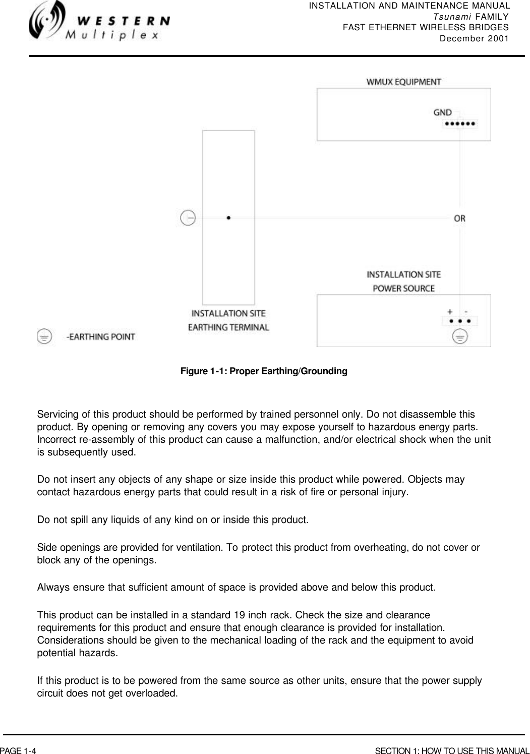

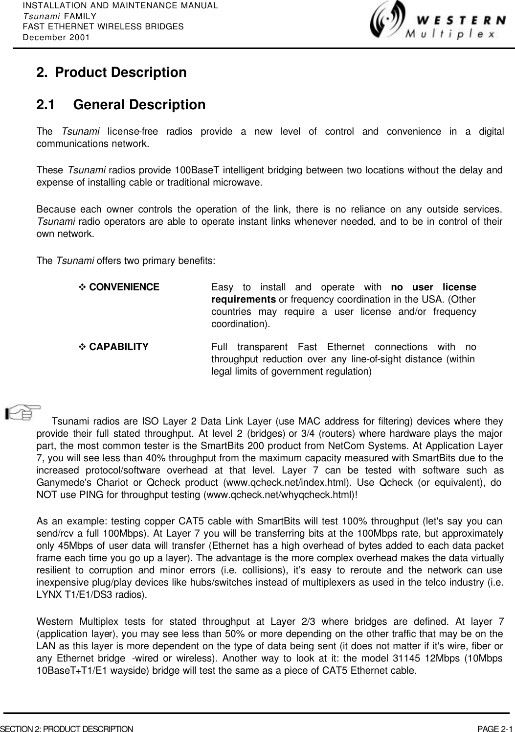
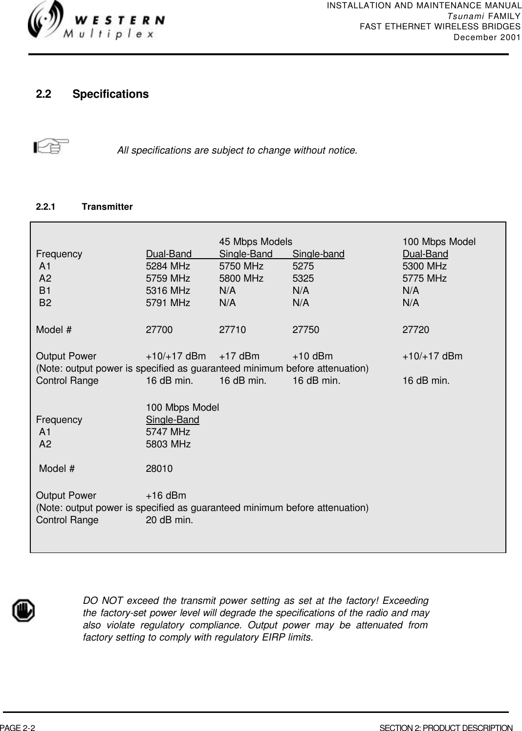
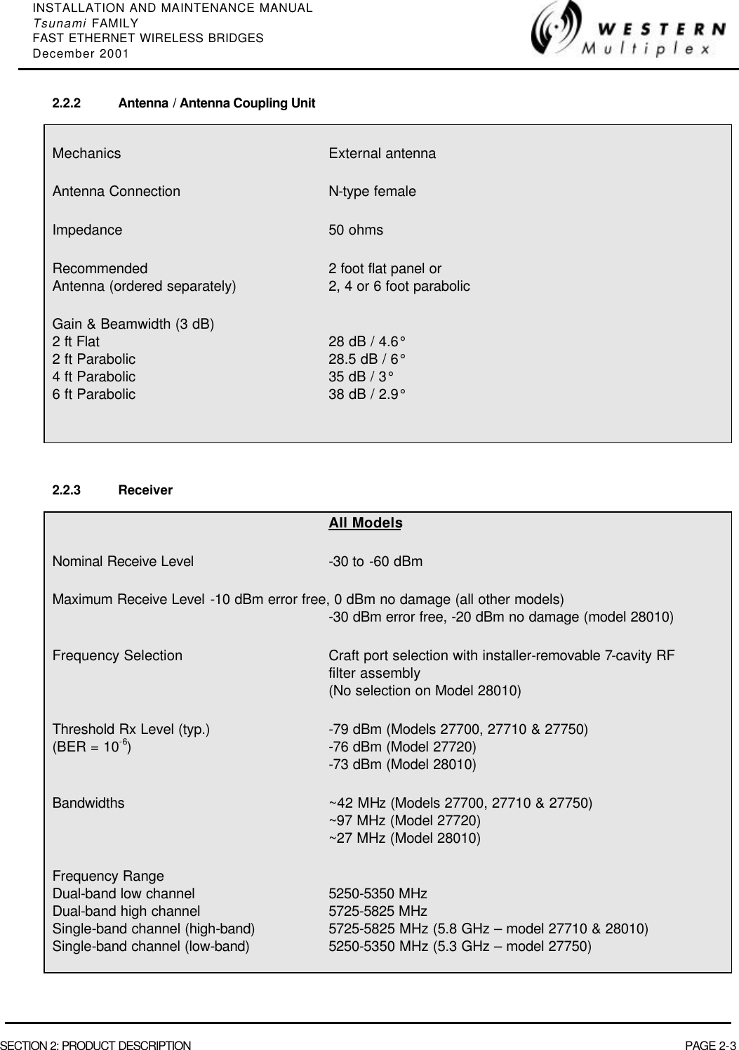
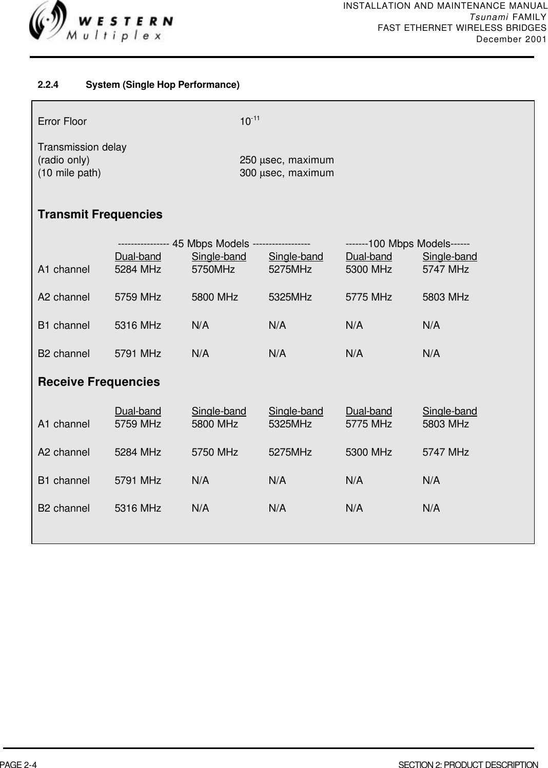


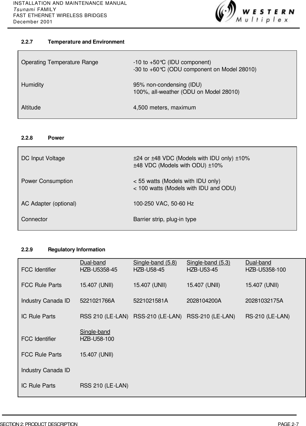
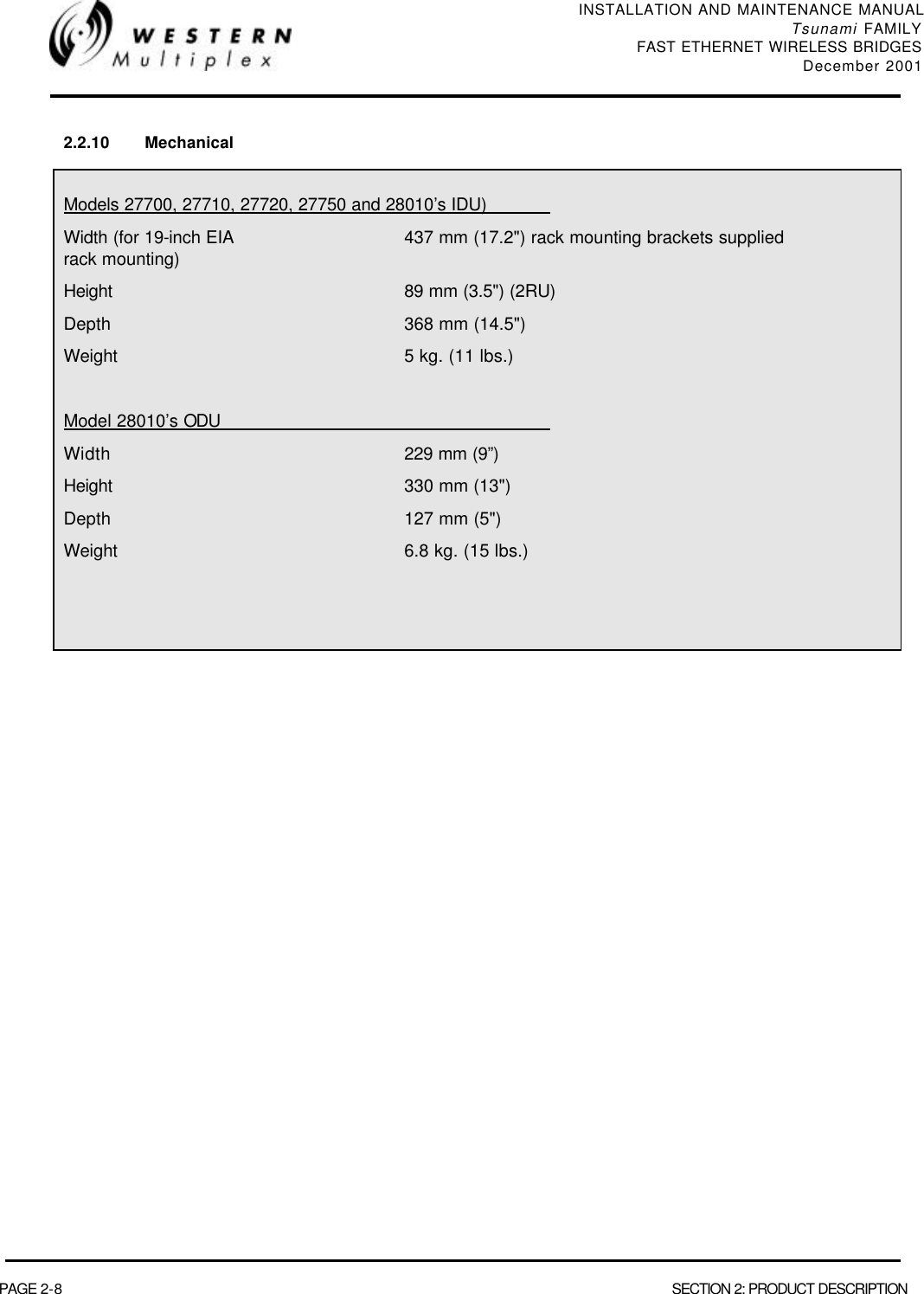
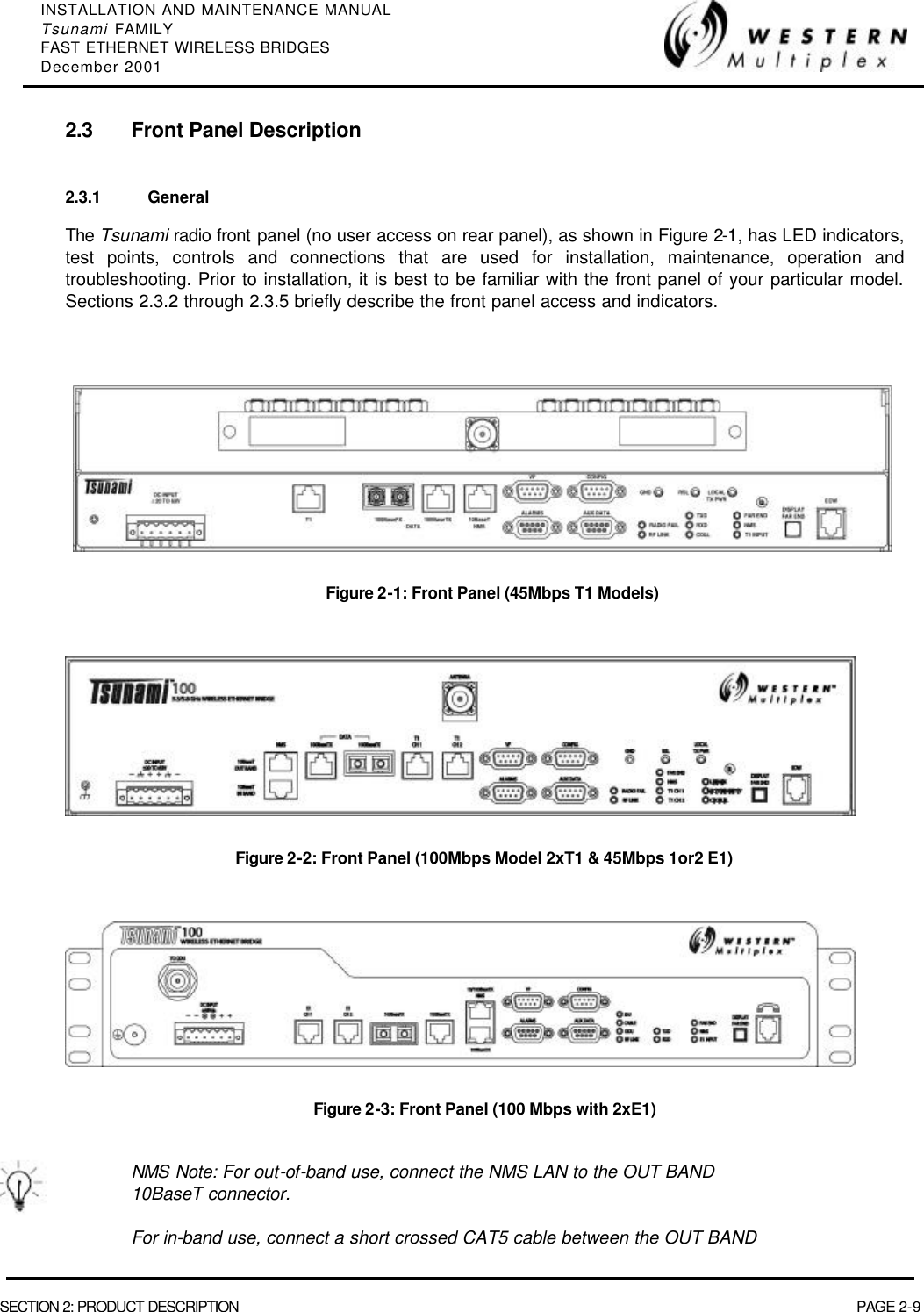
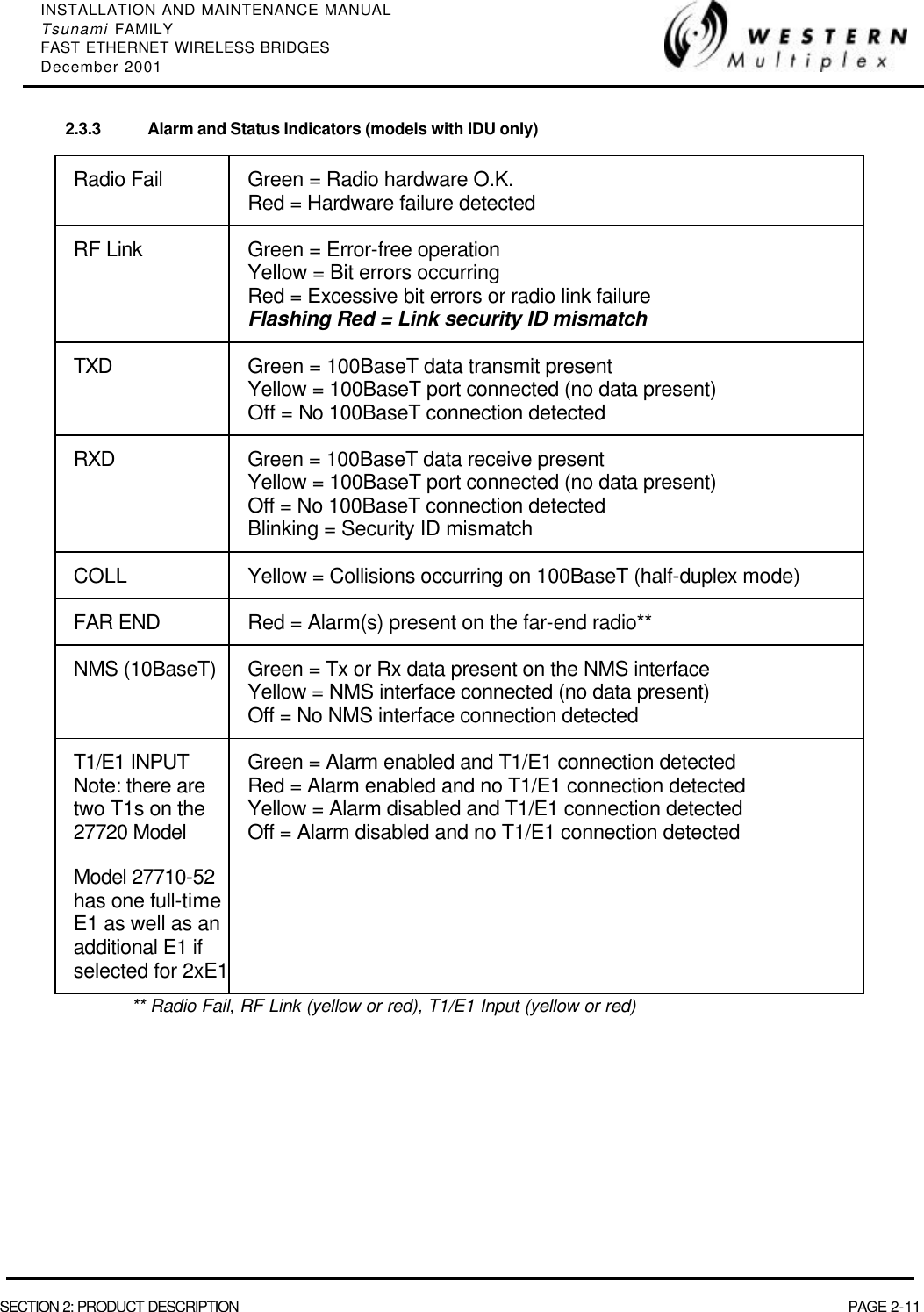
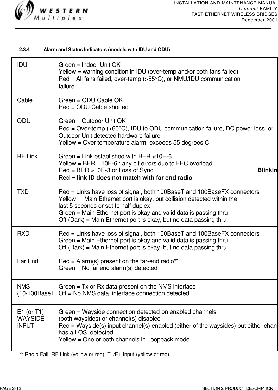
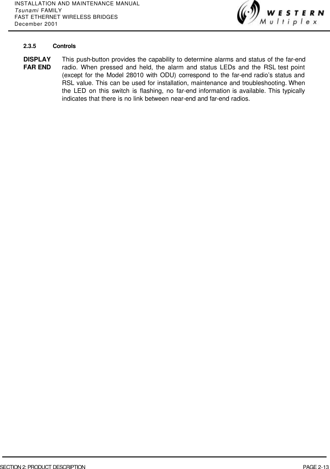
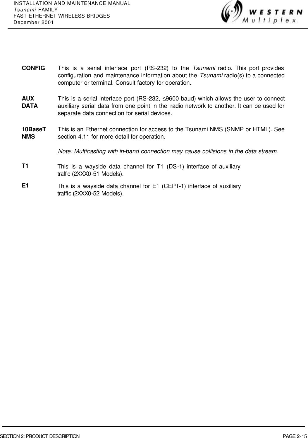
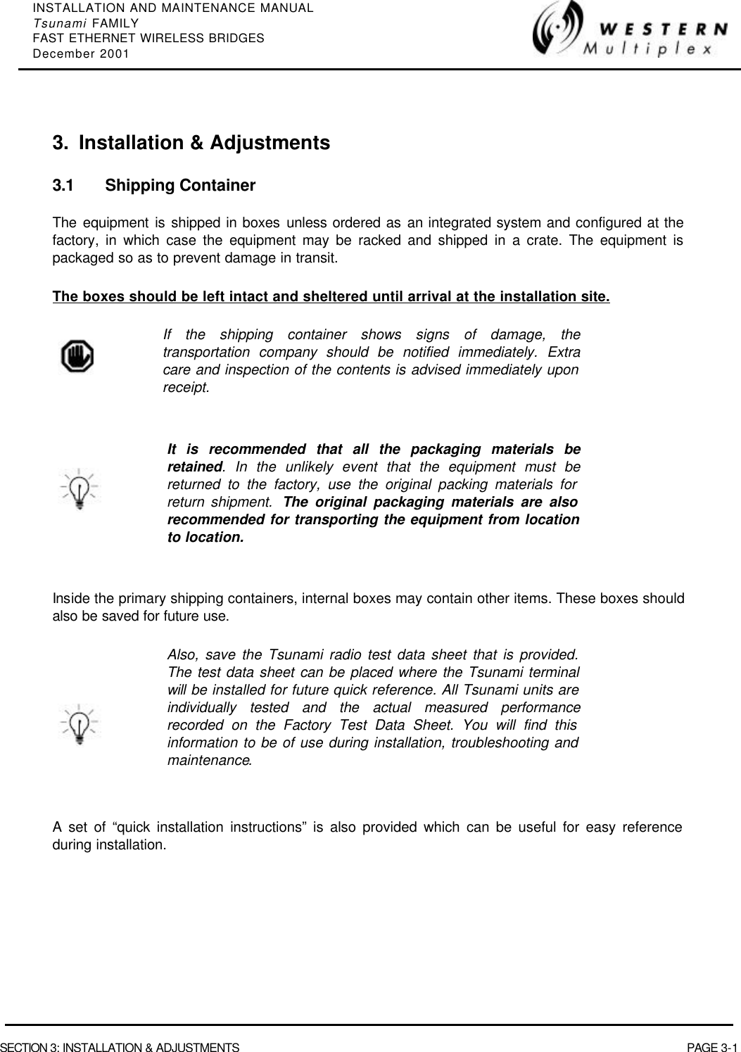
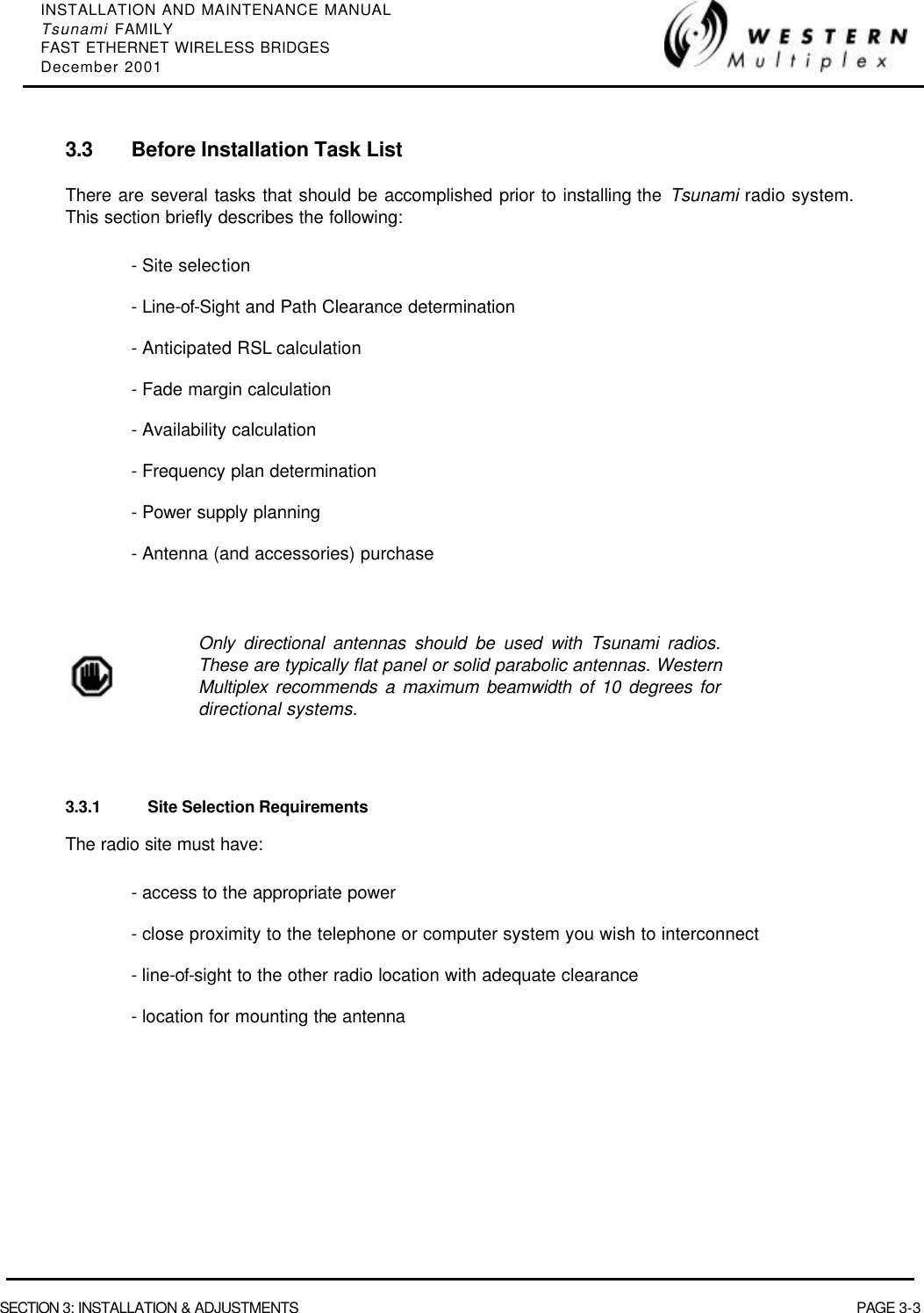
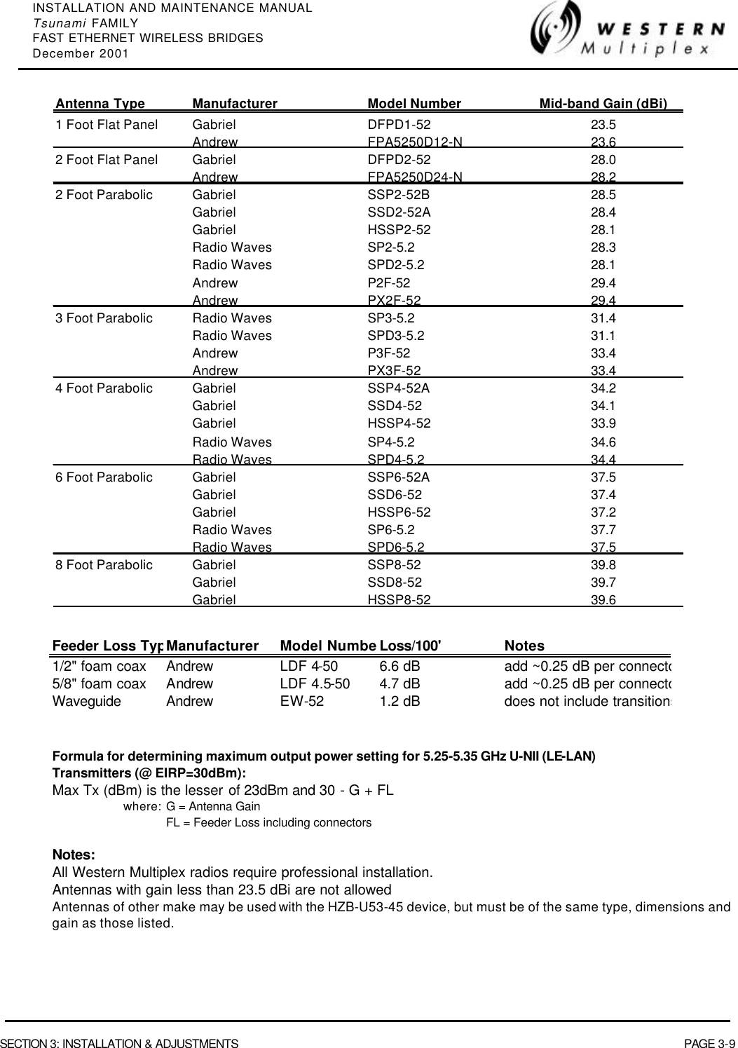
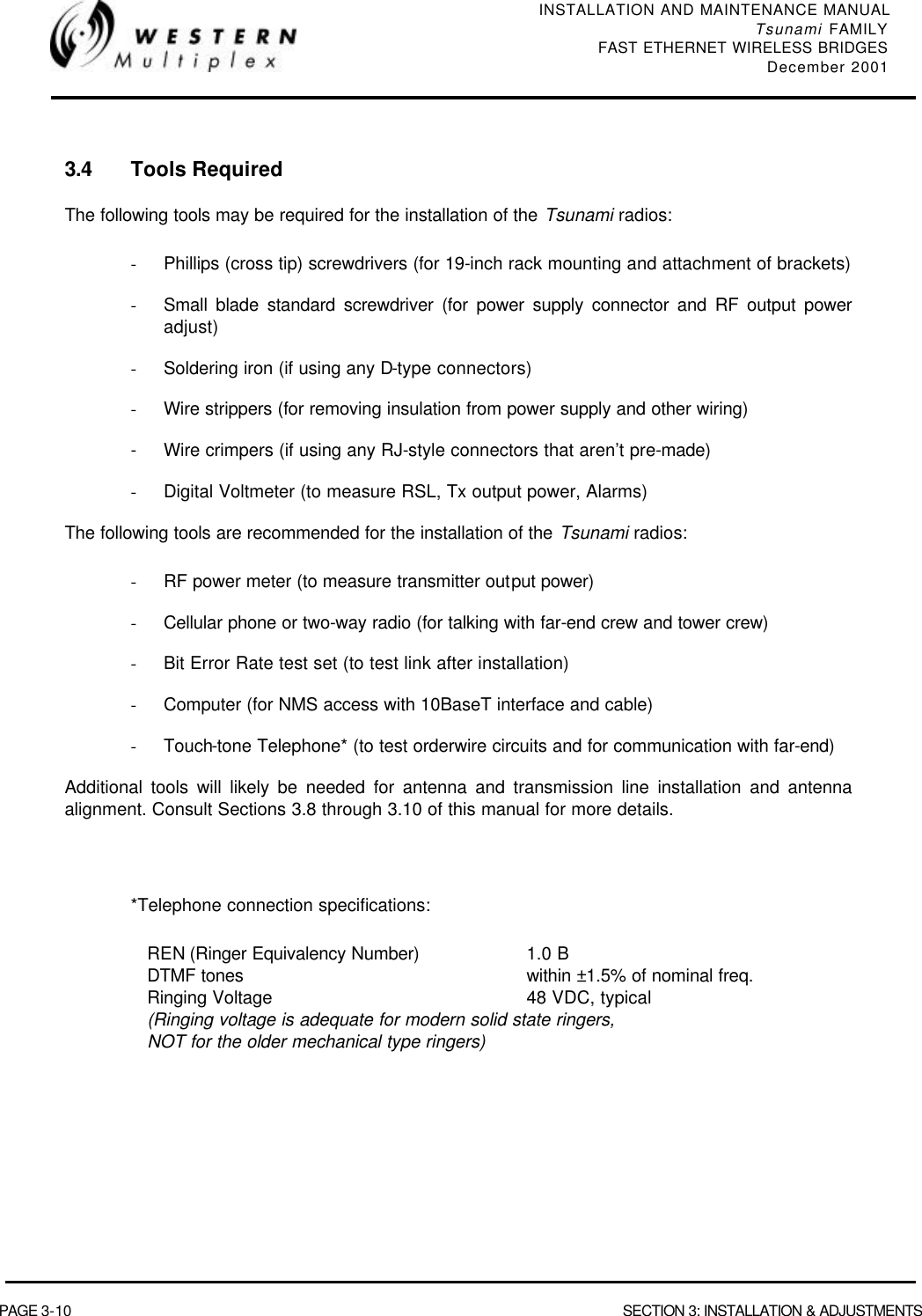
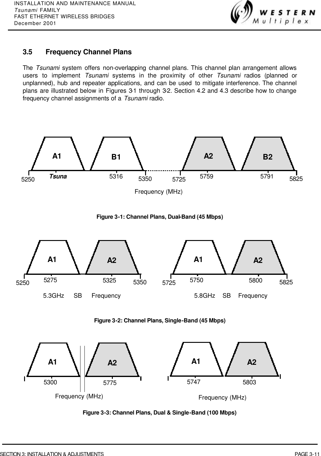
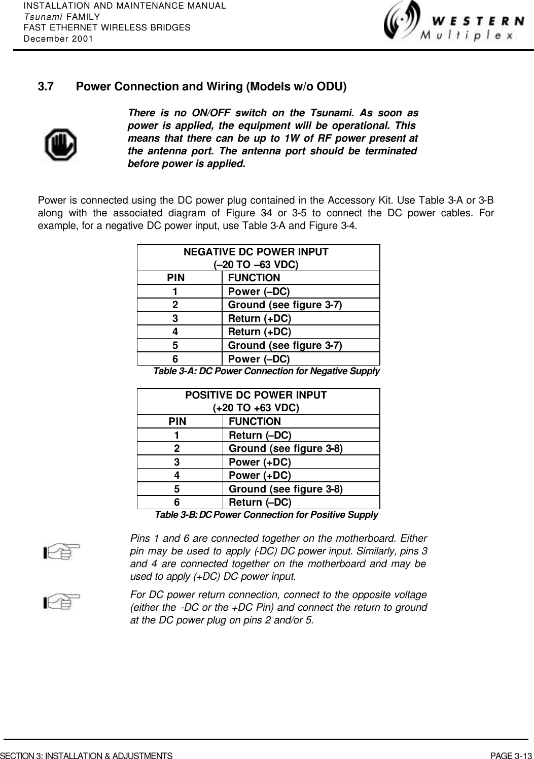
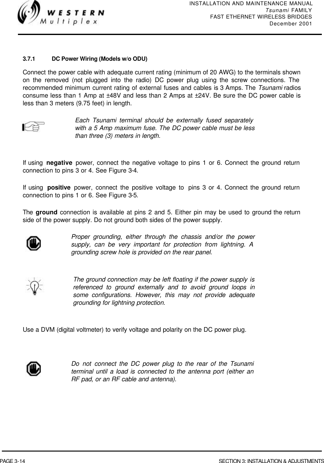
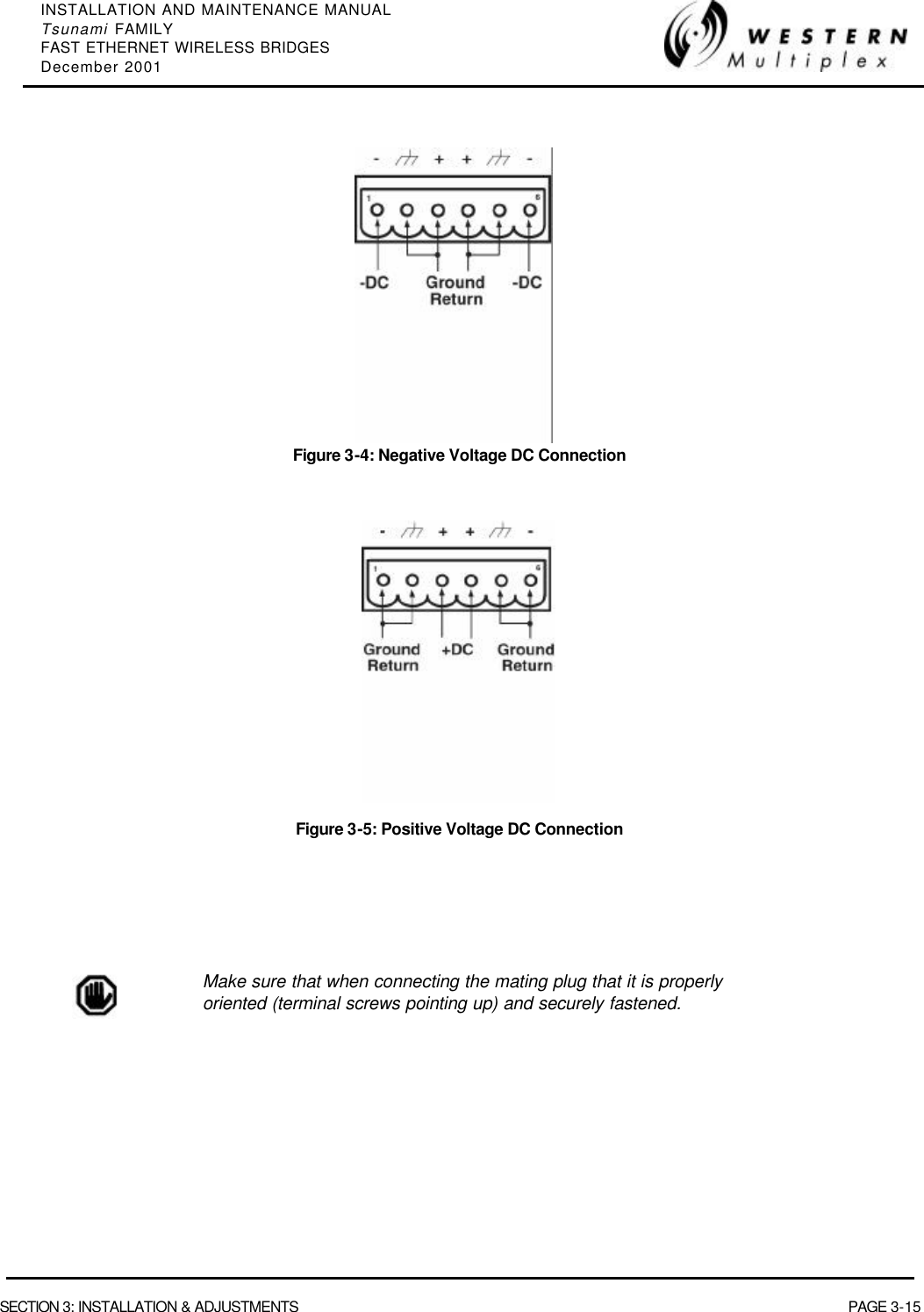
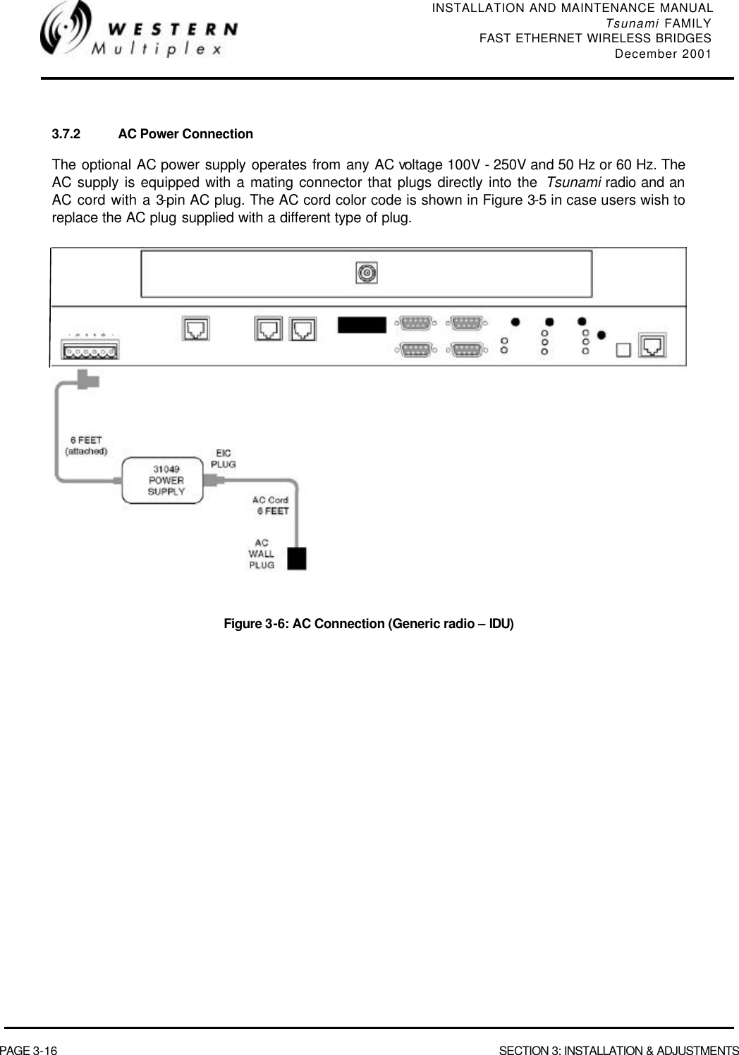
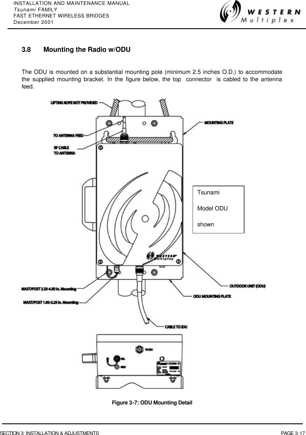
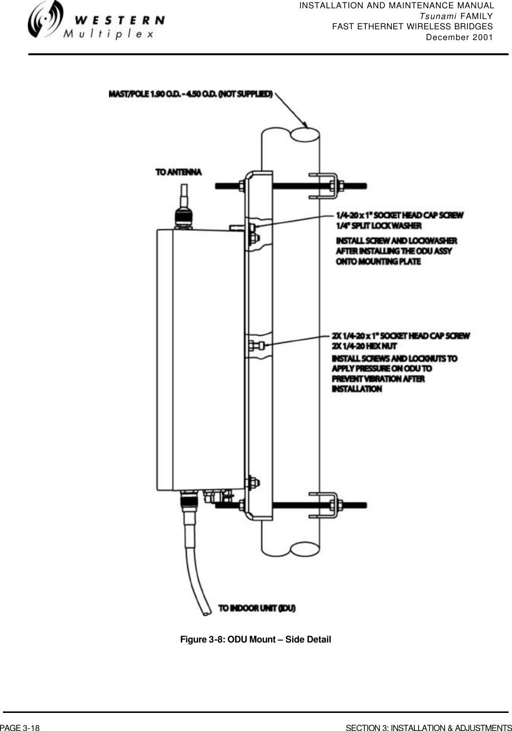
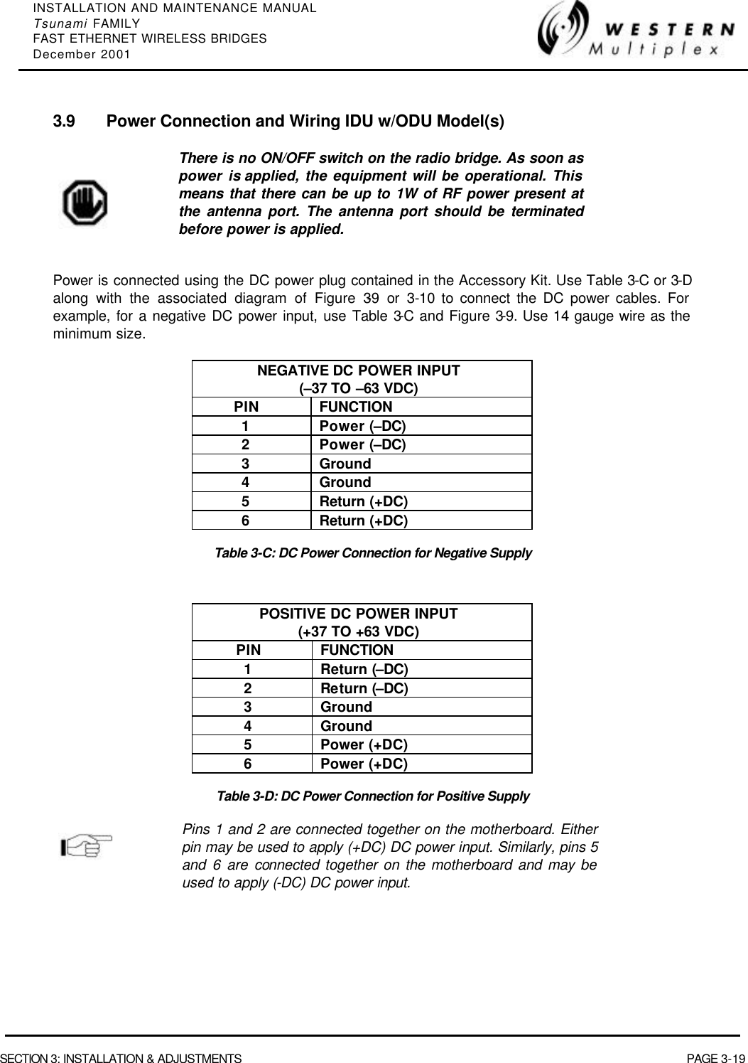
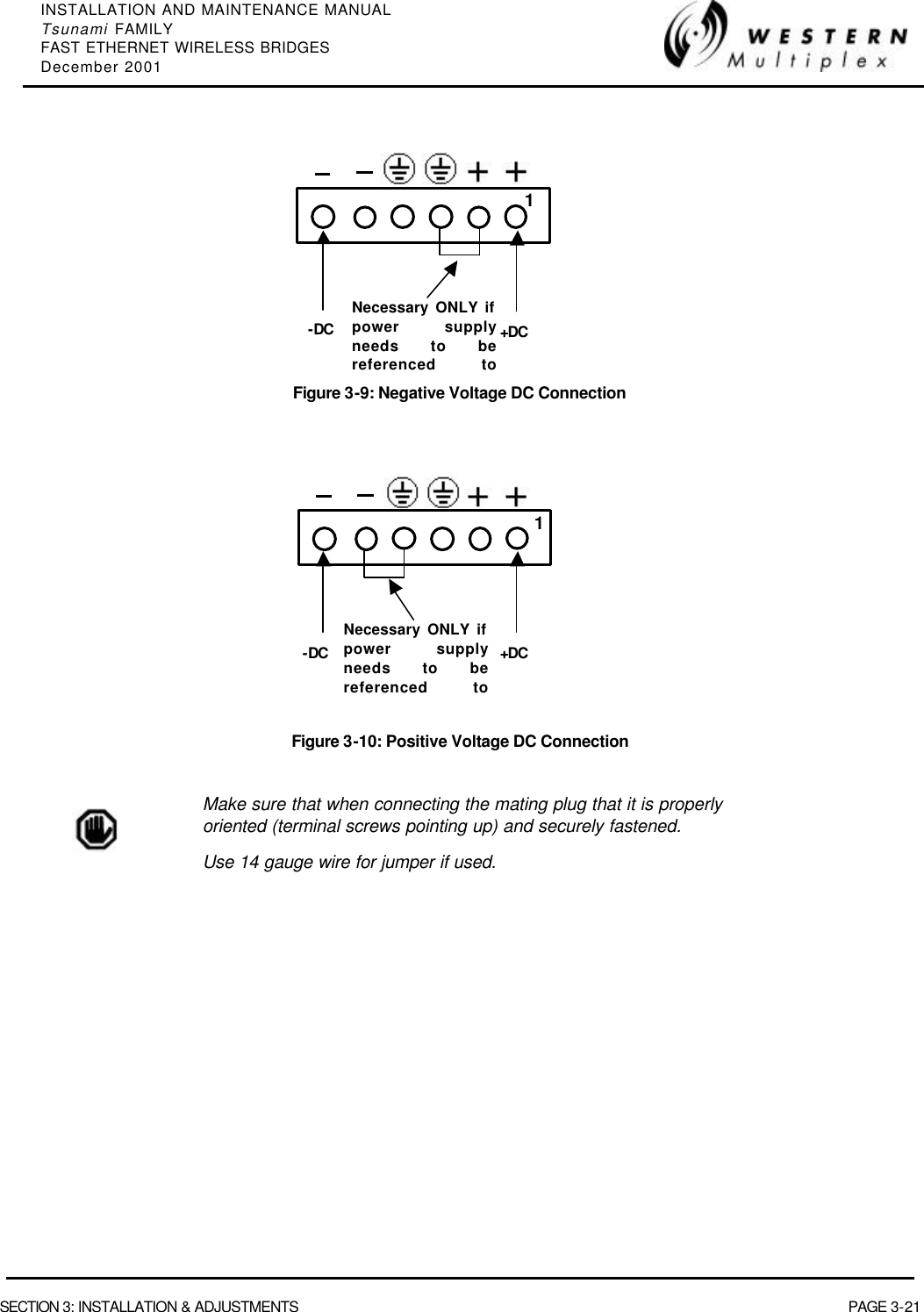
![INSTALLATION AND MAINTENANCE MANUAL Tsunami FAMILY FAST ETHERNET WIRELESS BRIDGES December 2001 PAGE 2-14 SECTION 2: PRODUCT DESCRIPTION 2.3.6 Connections RF CONNECTION The RF port of the Tsunami radio is an N-type female connector that is an integral part of the filter assembly. The filter assembly occupies nearly the entire top half of the front panel. The N-Type connector is used to connect the antenna, typically using coaxial transmission line. In some cases, waveguide may be used as the primary transmission line, in which case a waveguide-to-N adapter is required. For the Tsunami, 1/2" or 5/8” coaxial cable (LDF4-50 or LDF4.5-50) is recommended. Coaxial cable that is 7/8” or larger can exhibit moding at 5.8 GHz and is not recommended for 5.8 GHz radios. For waveguide transmission line at 5.8 GHz, EW-52 waveguide is recommended. EW-63 will also work, but may exhibit more loss. DATA CONNECTION The connection for the Fast Ethernet interface that carries the signals in and out of the radio is an RJ45 100BaseT wire connection or ST 100BaseT fiber connection. DC POWER CONNECTION The input accepts positive or negative DC power at any voltage between 20 and 63 Volts. Optionally, an AC power adapter can be used. OPTIONAL CONNECTIONS There are several connections that are not required for operation, but provide additional facilities to the user. EOW VF This connection is used to access the electronic orderwire function. This is a facility for "telephone" style service from one radio to another. A standard electronic telephone [one with a handset and DTMF (push-button tone) dialing] plugs into this connector. The user can dial the orderwire address of the far-end radio (or any radio in the Tsunami network) to establish telephone communication between sites. This communication does not interrupt or interfere with the other radio communications. The radio link must be operational to use this facility. The orderwire feature can be very useful for installation, maintenance and troubleshooting. This connector is used to link two Tsunami radios at a repeater site for Orderwire operation. This would allow orderwire "telephone" calls to and from any point in the Tsunami network. This circuit is 4-wire audio (2xTx and 2xRx) The Tsunami orderwire circuit can also be connected to other existing orderwire networks. See Section 3.14.1 for details. ALARM This connector is used for monitoring alarms electrically. The Form C relays can be connected to other transmission equipment for monitoring alarm status locally or remotely.](https://usermanual.wiki/Proxim-Wireless/U58-100/User-Guide-232292-Page-36.png)