Proxim Wireless U58-45 User Manual Users manual
Proxim Wireless Corporation Users manual
UserManual.wiki
>
Proxim Wireless
>
U58-45 User Manual
>
Users manual
Contents
1.
Users manual
2.
Updated Installation and Maintenance Manual
3.
Modified page regarding RF exposure warning
4.
Modified page
Users manual
Navigation menu
Upload a User Manual
Namespaces
Wiki Guide
HTML
PDF
Info
Views
User Manual
Discussion / Help
Navigation


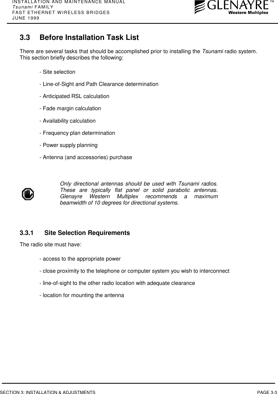
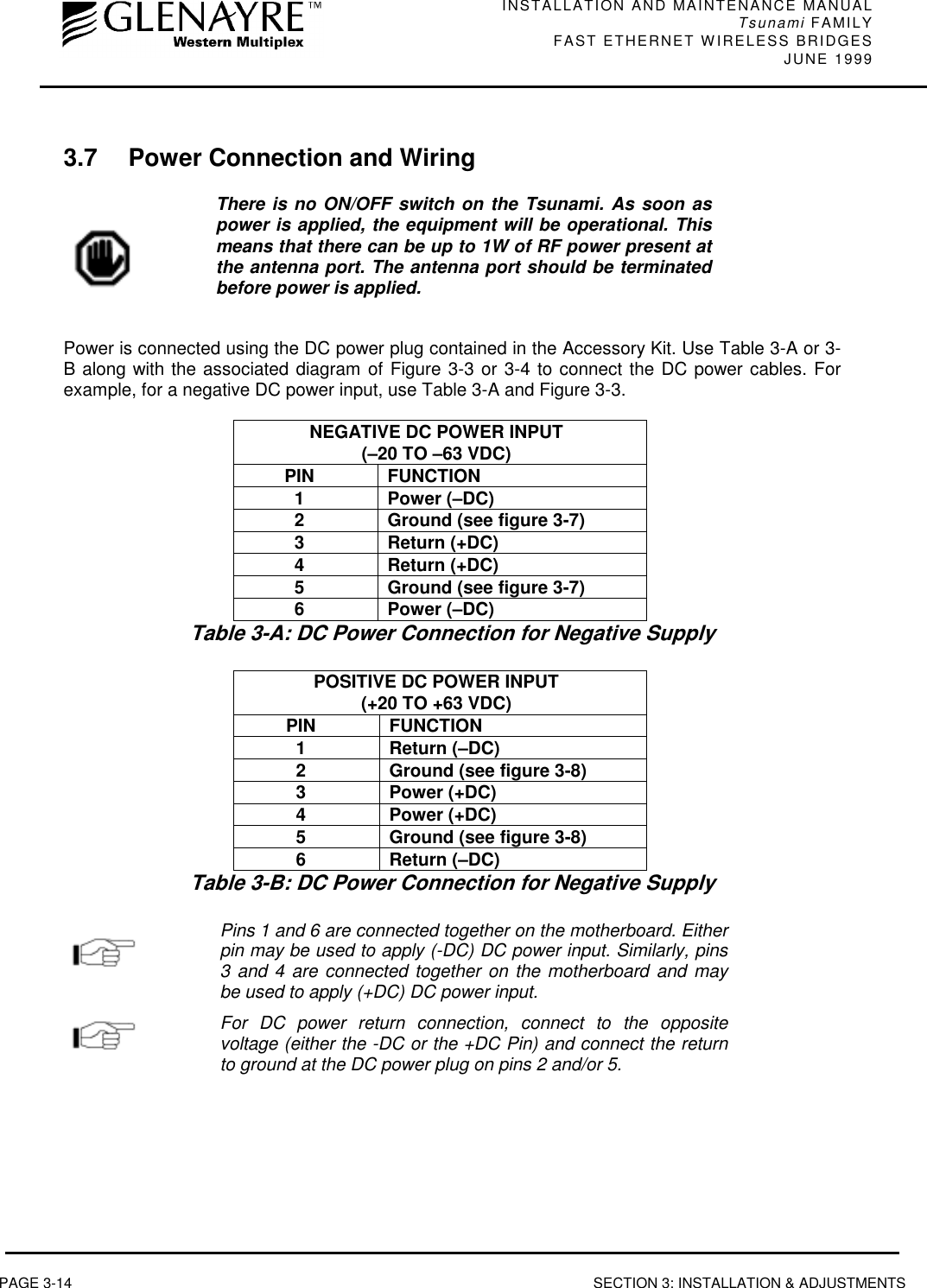
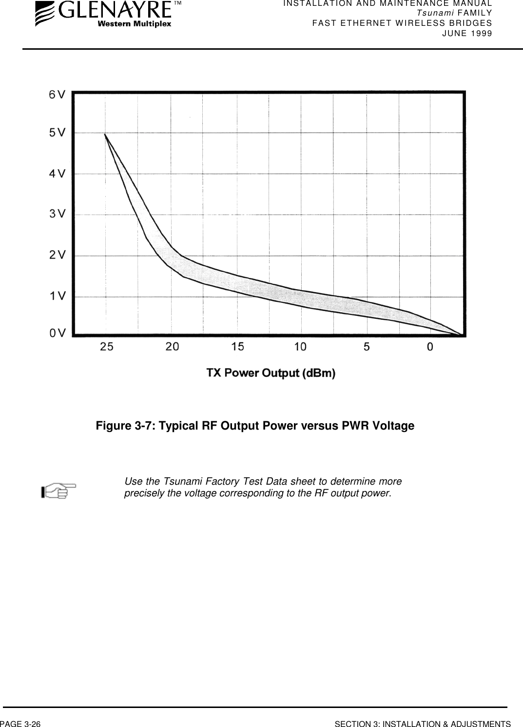
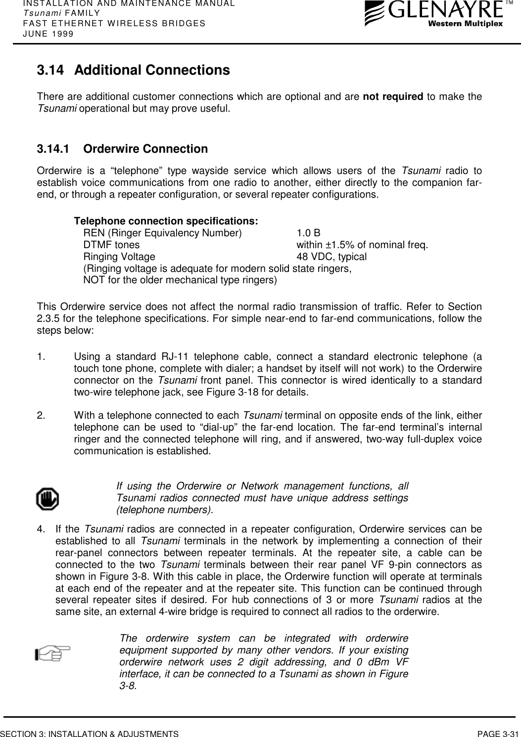
![INSTALLATION AND MAINTENANCE MANUALTsunami FAMILYFAST ETHERNET WIRELESS BRIDGES JUNE 1999PAGE 2-14 SECTION 2: PRODUCT DESCRIPTION2.3.5 ConnectionsELECTRONIC ORDERWIRE (EOW)This connection is used to access the orderwire function. This is a facility for "telephone" style servicefrom one radio to another. A standard electronic telephone [one with a handset and DTMF (push-button tone) dialing] plugs into this connector. The user can dial the orderwire address of the far-endradio (or any radio in the Tsunami network) to establish telephone communication between sites. Thiscommunication does not interrupt or interfere with the other radio communications. The radio linkmust be operational to use this facility. The orderwire feature can be very useful for installation,maintenance and troubleshooting.- Touch-tone Telephone* (for communication with far-end)*Telephone connection specifications:REN (Ringer Equivalency Number) 1.0 BDTMF tones within ±1.5% of nominal freq.Ringing Voltage 48 VDC, typical(Ringing voltage is adequate for modern solid state ringers,NOT for the older mechanical type ringers)RF CONNECTIONThe RF port of the Tsunami radio is an N-type female connector that is an integral part of the filterassembly. The filter assembly occupies nearly the entire top half of the front panel. The N-Typeconnector is used to connect the antenna, typically using coaxial transmission line. In some cases,waveguide may be used as the primary transmission line, in which case a waveguide-to-N adapter isrequired.For the Tsunami, 1/2" or 5/8” coaxial cable (LDF4-50 or LDF4.5-50)is recommended. Coaxial cable that is 7/8” or larger can exhibitmoding at 5.8 GHz and is not recommended for 5.8 GHz radios.For waveguide transmission line at 5.8 GHz, EW-52 waveguide isrecommended. EW-63 will also work, but may exhibit more loss.DATA CONNECTIONThe connection for the Fast Ethernet interface that carries the signals in and out of the radio is a RJ45100BaseT wire connection or ST 100BaseT fiber connection.](https://usermanual.wiki/Proxim-Wireless/U58-45.Users-manual/User-Guide-48379-Page-30.png)