Proxim Wireless U58-B60 Unlicensed NII Base Station Transceiver User Manual P2mPv001d3 fcc
Proxim Wireless Corporation Unlicensed NII Base Station Transceiver P2mPv001d3 fcc
Users Manual

WESTERN MULTIPLEX CORPORATION
Installation and Maintenance Manual
Multipoint
MAN 40000-001d1

TSUNAMI MULTIPOINT
iiii
Revisions:
September 2001 Draft
October FCC submittal

WESTERN MULTIPLEX CORPORATION
Tsunami Point-to-Multipoint
2001
Western Multiplex Corporation
1196 Borregas Avenue
Sunnyvale, California 94089 USA
Phone +1 408 542 5200 • Fax +1 408 542 5300
http://www.wmux.com
ftp://ftp.wmux.com/products/

ii
Table of Contents
1. INTRODUCTION............................................................................................................................ 1-1
PRODUCT HIGHLIGHTS......................................................................................................................... 1-2
KEY FEATURES.................................................................................................................................... 1-3
HOW TO USE THIS MANUAL....................................................................................................................... 1-3
SAFETY INSTRUCTIONS............................................................................................................................... 1-4
2. SYSTEM OVERVIEW ..................................................................................................................... 2-1
SITE PLANNING CONSIDERATIONS............................................................................................................... 2-2
General Considerations.......................................................................................................................... 2-2
Weather................................................................................................................................................ 2-3
Antennas............................................................................................................................................... 2-5
Path Planning........................................................................................................................................ 2-6
WIRELESS: FREQUENTLY ASKED QUESTIONS................................................ ERROR! BOOKMARK NOT DEFINED.
3. QUICK SET-UP PROCEDURE........................................................................................................ 3-1
Important Configuration Notes................................................................................................................ 3-1
Unpacking the System............................................................................................................................. 3-1
SOFTWARE INSTALLATION.......................................................................................................................... 3-4
HUB SITE EQUIPMENT CONFIGURATION (BSU)............................................................................................. 3-5
SUBSCRIBER UNIT CONFIGURATION............................................................................................................. 3-8
Mechanical Considerations – Mounting Units........................................................................................... 3-9
4. SPECIFICATIONS ........................................................................................................................ 4-11
SYSTEM.............................................................................................................................................. 4-11
STANDARDS COMPL LANCE AND INTERFACES................................................................................ 4-12
CONFIGURATION AND MANAGEMENT............................................................................................. 4-12
POWER /ENVIRONMENT /SAFETY...................................................................................................... 4-12
PHYSICAL DIMENSIONS .................................................................................................................... 4-13
MOUNTING (INSTALLATION)............................................................................................................. 4-13

TSUNAMI MULTIPOINT
ii
Figures
FIGURE 1-1-1: P ROPER EARTHING/GROUNDING................................................................................................ 1-5
FIGURE 2-2-1: EACH HUB IS MADE UP OF ONE TO SIX BASE STATIONS AND MULTIPLE REMOTES(SUS)................... 2-1
FIGURE 3-3-1: SUBSCRIBER UNIT.................................................................................................................... 3-3
FIGURE 3-2 SUBSCRIBER ODU ................................................................................................................... 3-9
FIGURE 3-3: BASE STATION ODU................................................................................................................. 3-10

TSUNAMI MULTIPOINT
1-1
1. Introduction
sunami Multipoint is a point-to-multipoint outdoor wireless system offering a
high-capacity alternative to wired data networks. Using IP packet radio
transmitters, standard Ethernet interfaces, and an easy to-deploy design, the
Tsunami Multipoint system enables high-speed network connections to
multiple Ethernet switches, routers or PCs from a single location. With Tsunami
Multipoint, you can now avoid the delays and costs associated with wired connections
such as DSL, cable modems, and leased T I /E I lines. Tsunami Multipoint eliminates
wire/fiber installation costs and recurring monthly fees - delivering carrier-class
performance at an affordable price.
Tsunami Multipoint systems consist of one or more Subscriber Units that
communicate with a Base Station to provide high-performance wireless network
connections.
EXTEND OR ENHANCE YOUR NETWORK OVERNIGHT
With Tsunami Multipoint, there are no DSL, cable, or leased-line hassles to negotiate.
You no longer have to worry about man-made barriers to overcome. Easy installation
and operation allow network planners to quickly deploy up to 60 Mbps capacity
between locations, making it the ideal solution for:
§ Establishing high-speed connections between Internet Service Providers and their
customers
§ Organizations requiring high-capacity WAN connectivity between multiple buildings or
campuses
§ Organizations or service providers seeking network redundancy for mission critical wired
connections
Chapter
1
T

TSUNAMI MULTIPOINT
1-2
ABOUT THE TSUNAMI PRODUCT FAMILY
The Tsunami family of Ethernet bridges provides wireless solutions that meet the
growing demand for transparent and reliable high-speed network interconnectivity.
In addition to Tsunami Multipoint for point-to-multipoint connections, the Tsunami
product line includes the following point-to-point offerings:
Tsunami 1OBaseT, a cost-effective, high-capacity alternative to multiple wireline T1
connections.
Tsunami 10OBaseT/F, a cost-effective, high-capacity alternative to wireline DS3
connections.
Tsunami 100OBaseSX, the world's first Ethernet bridge to provide gigabit, wireless
connectivity for native IP connections.
PRODUCT HIGHLIGHTS
UP TO 360 MBPS PER HUB SITE
§ Speeds from 20 Mbps to 60 Mbps Time Division Duplex (TDD) per Base Station for
optimal network efficiency
§ Configurable upstream/downstream bandwidth to optimize desired throughput
§ Six Base Stations provide 360 degree coverage, delivering up to 360 Mbps per hub site
FAST AND EASY TO DEPLOY & MANAGE
§ Subscriber Unit simplicity enables self installation to minimize deployment costs
§ Audible beeper alignment eases installation
§ Subscriber Unit with integrated antenna connects to indoor power & networks using a
single CAT5 cable
§ "Over the air" software upgrades minimize subscriber unit maintenance costs

TSUNAMI POINT-TO-MULTIPOINT
1-3
RAPID RETURN ON INVESTMENT
§ Rapid, easy deployment enables quick service activation, reduced costs and faster payback
§ High-capacity connection enables faster network traffic to deliver new service offerings
PURE ETHERNET CONNECTIVITY
§ Operates in either Ethernet bridging or IP routing modes with direct connections to PCs,
Fast Ethernet switches & routers
§ Support for VLAN tagging
KEY FEATURES
§ Flexible throughput rates: 20, 30, 40, & 60 Mbps TDD
§ 5.8 GHz license-exempt frequency band
§ Compliant with industry standards
§ Base Station provides 60 degree antenna - six Base Stations cover 360 degrees
§ Network management through SNMP & Java-based "Wireless Manager" software
§ Point-to-multi point communications from less than 1 mile/kilometer to more than 8
miles/ 13 kilometers
How to Use This Manual
The “icon key” at left will be used to “highlight” specific text
to call particular attention to it. Where specific emphasis needs
to be placed, these icons will direct you to other information or
particular areas where additional information can be found.
ICON KEY
i Information
[ Suggestion
N Caution
F Note
@ Write this down

TSUNAMI MULTIPOINT
1-4
Safety Instructions
IMPORTANT
This product has been evaluated to the U.S. and Canadian (Bi-National) Standard for
Safety of Information Technology Equipment, Including Electrical Business
Equipment, CAN/CSA C22.2, No. 950-95 * UL 1950, Third Edition, including
revisions through revision date March 1, 1998, which are based on the Fourth
Amendment to IEC 950, Second Edition. In addition, this product was also evaluated
to the applicable requirements in UL 1950, Annex NAE.
WARNING - This unit is intended for installation in a Restricted Access location in
accordance with Articles 110-18, 110- 26, and 110-27 of the United States National
Electric Code ANSI/NFPA 70.
This equipment should be installed in accordance with Article 810 of the United States
National Electrical Code.
When installed, this equipment is intended to be connected to a Lightning/Surge
Protection Device that meets all applicable national Safety requirements.
Equipment is to be used and powered by the type of power source indicated on the
marking label only.
This product is intended to be connected to an AC power source which must be
electrically isolated from any ac sources and reliably earthed. Only an AC power
source that complies with the requirements in the Standard for the Safety of
Information Technology Equipment, Including Electrical Business Equipment,
CAN/CSA C22.2, No. 950-95 * UL 1950, Third Edition, can be used with this
product. A 15-Amp circuit breaker is required at the power source. In addition, an
easily accessible disconnect device should be incorporated into the facility wiring.
Always use copper conductors only for all power connections.
WARNING - This equipment is intended to be earthed. If you are not using the
power supply provided by Western Multiplex, you will need to connect the earthing
conductor of your power source to the earthing terminal located on the back of the
unit; or, connect an earthing conductor between the unit’s earthing terminal and your
earthing point. See Ill. for instructions. For safe operation, always ensure that the unit
is earthed properly as described in this manual and per Figure 1-1.
Do not connect or disconnect the power cable to the equipment when the other end
of the cable is connected to the dc power supply.

TSUNAMI MULTIPOINT
1-5
Figure 1-1-1: Proper Earthing/Grounding
Servicing of this product should be performed by trained personnel only. Do not
disassemble this product. By opening or removing any covers you may expose
yourself to hazardous energy parts. Incorrect re-assembly of this product can cause a
malfunction, and/or electrical shock when the unit is subsequently used.
Do not insert any objects of any shape or size inside this product while powered.
Objects may contact hazardous energy parts that could result in a risk of fire or
personal injury.
NOTE:
This equipment has been tested and found to comply with the limits for a Class B
digital device, pursuant to Part 15 of the FCC Rules. These limits are designed to
provide reasonable protection against harmful interference in a residential installation.
This equipment generates, uses and can radiate radio frequency energy and, if not
installed and used in accordance with the instructions, may cause harmful
interference to radio communications. However, there is no guarantee that
interference will not occur in a particular installation. If this equipment does cause
harmful interference to radio or television reception, which can be determined by
turning the equipment off and on, the user is encouraged to try to correct the
interference by one or more of the following measures:
• Reorient or relocate the receiving antenna.
• Increase the separation between the equipment and receiver.
• Connect the equipment into an outlet on a circuit different from that to which the
receiver is connected.
• Consult the dealer or an experienced radio/TV technician for help.

TSUNAMI MULTIPOINT
1-6
CAUTION
The outdoor units of the Tsunami Multipoint products must be fixed mounted on
permanent structures with a separation distance of at least 1.5 meters from all
persons during normal operation.
CAUTION:
Changes or modifications not expressly approved by the party responsible for
compliance could void the user's authority to operate the equipment
TSUNAMI MULTIPOINT
2-1
2. System Overview
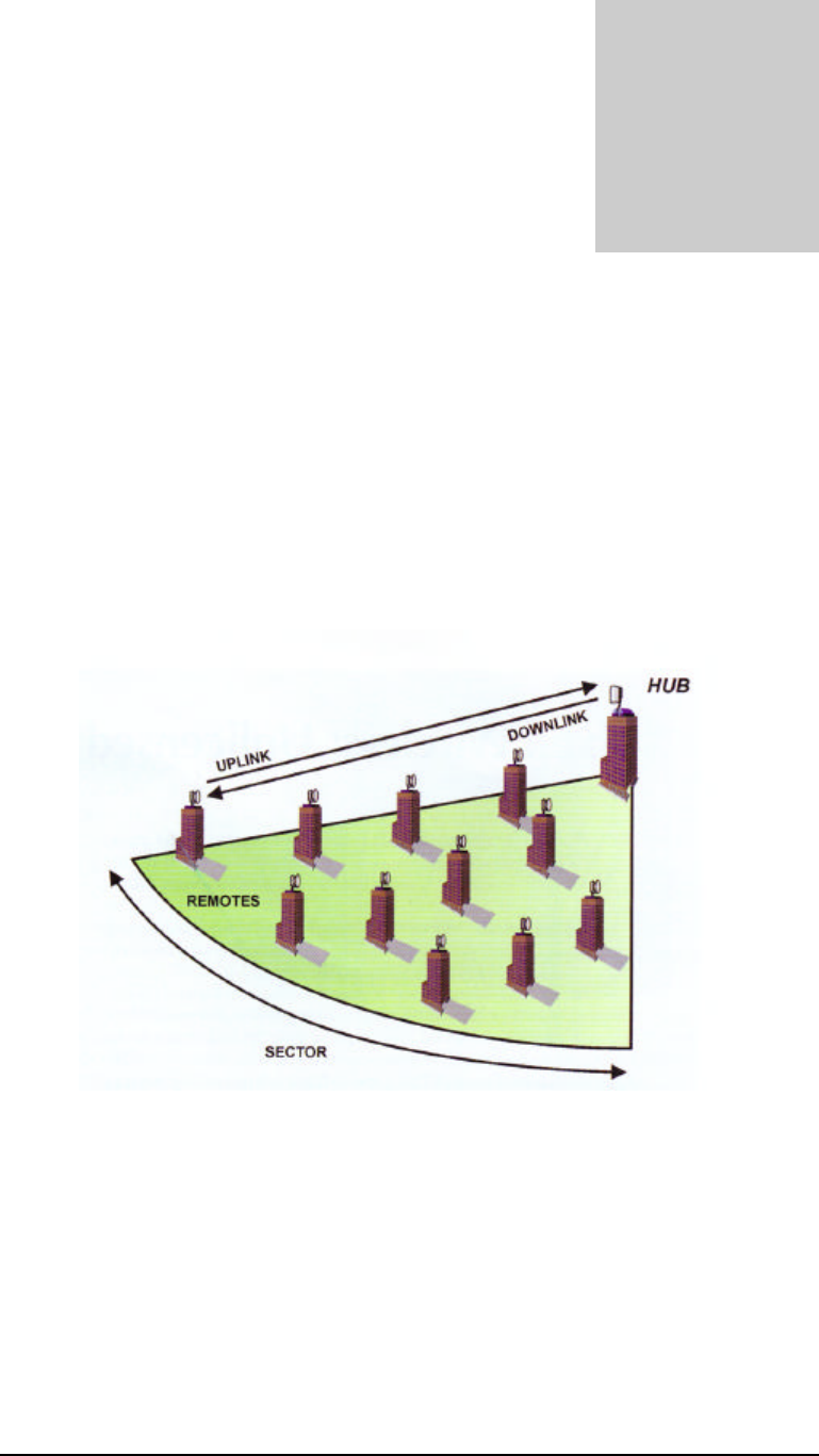
A system is made up of one to six Base Stations that make up a Hub (or cell) with
each Base Station communicating with their associated SUs (Subscriber Units).
Together, they provide a wide coverage, high-capacity system that transfers IP traffic
between the Hub and its multiple SUs. Each Hub has the ability to communicate in all
directions using up to six sectors of 60 degrees each. Each of the Hub’s six sectors has
the capability of communicating 20, 30, 40 or 60 Mbps in total bandwidth allowing a
maximum of 360 Mbps per Hub.
Figure 2-2-1: Each HUB is made up of one to six Base Stations and multiple
remotes(SUs)
Uplink and Downlink, each SU communicates with it Hub in a coordinated manner so that
all other remotes within its Hub’s jurisdiction. All SUs are very quickly handled on a case by
case basis giving the user at the SU that they are in constant communication with its Hub’s
Sector.
.
Chapter
2

TSUNAMI MULTIPOINT
2-2
Site Planning Considerations
The installation of a wireless network requires much the same basic planning as any
wired network. The main difference is that the wireless signal requires some additional
planning. This planning includes RF path planning, site preparation, and installation of
outdoor components such as outdoor units, antennas, lightning protection devices,
and cabling suitable for outdoor conditions.
Although the technology implemented in this broadband fixed wireless system can
make use of multipath signals, reducing the effect of obstructions in the path, it is
important that the characteristics of the path be carefully examined. With this
knowledge, components and network requirements can be correctly planned for your
specific application.
This chapter provides insight into the planning necessary to prepare your site for your
broadband fixed wireless system.
General Considerations
A basic consideration is the physical location of the sites at each end of the link.
Because microwave signals travel in a straight line, a clear line of sight between
antennas is ideal. Frequently, however, the locations of the desired links are fixed.
When a clear line of sight cannot be achieved, you must plan accordingly.
Other general site considerations include:
a. Will a tower have to be constructed? Are permits required?
b. Possibility of future obstructions-Will trees grow high enough to interfere
with the signal? Are there plans to erect buildings between the sites that may
obstruct the path?
c. Availability of grounding-Good grounding is important in all areas of the
world, but in areas prone to lightning, it is especially critical.
d. Availability of power-Are redundant power systems available if the area is
prone to outages?
The planning of a wireless link involves collecting information and making decisions.
The following sections will help you determine which information is critical to the site
and will be an aid in the decision-making process.

TSUNAMI MULTIPOINT
2-3
Weather
It is important to research any unusual weather conditions that are common to the site
location. These conditions can include excessive amounts of rain, wind velocity or
extreme temperature ranges. If extreme conditions exist that may affect the integrity of
the radio link, it is recommended that these conditions be taken into consideration
early in the planning process.
RAIN
Except in extreme conditions, attenuation (weakening of the signal) due to rain does
not require serious consideration for frequencies up to the range of 6 or 8 GHz. When
microwave frequencies are at 10 or 12 GHz or above, attenuation due to rain becomes
much more of a concern, especially in areas where rainfall is of high density and long
duration. The systems discussed in this manual operate at frequencies below 6 GHz,
so rain is not a concern.
Temperature can adversely affect the radio link when such as temperature inversion,
or very still air accompanied by stratification. Temperature inversion can negate
clearances, and still air along with stratification can cause severe refractive or reflective
conditions, with unpredictable results. Temperature inversions and stratification can
also cause ducting, which may increase the potential for interference between systems
that do not normally interfere with each other. Where these conditions exist, it is
recommended that shorter paths and adequate clearances are used.
WIND
Any system components mounted outdoors will be subject to the effect of wind. It is
important to know the direction and velocity of the wind common to the site.
Antennas and their supporting structures must be able to prevent these forces from
affecting the antenna or causing damage to the building or tower on which the
components are mounted. Antenna designs react differently to wind forces, depending
on the area presented to the wind. This is known as wind loading.
Note For definitions of wind loading specifications for antennas and towers, refer
to TIA/EIA- 195 (for antennas) or TIA/EIA-222 (for towers) specifications.
LIGHTNING
The potential for lightning damage to radio equipment should always be considered
when planning a wireless link. A variety of lightning protection and grounding devices
are available for use on buildings, towers, antennas, cables, and equipment, whether
located inside or outside the site, that could be damaged by a lightning strike.
Lightning protection requirements are based on the exposure at the site, the cost of
link down-time, and local building and electrical codes. If the link is critical, and the

TSUNAMI MULTIPOINT
2-4
site is in an active lightning area, attention to thorough lightning protection and
grounding is critical.
LIGHTNING PROTECTION
To provide effective lightning protection, install antennas in locations that are unlikely
to receive direct lightning strikes, or install lightning rods to protect antennas from
direct strikes. Make sure that cables and equipment are properly grounded to provide
low-impedance paths for lightning currents. Install surge suppressors on adjacent
telephone lines and power lines.
Recommended is lightning protection for cables leading to the wireless ODU to/from
the power brick. The lightning protection should be placed at points close to where
the cable passes through the bulkhead into the building, as well as near the ODU.
CAT5 CABLE
When the entire control cable, from the building entrance to the ODU, is encased in
steel conduit, no surge arrestors are required. Otherwise, each control cable requires
one surge arrestor within two feet of the building entrance.
Note For installations with several radios, it may be more convenient to use a Type-
66 punch block with surge arrestors. A Type-66 punch block can accommodate up to
25 conductor pairs.
INTERFERENCE
An important part of planning your broadband fixed wireless system is the avoidance
of interference. Interference can be caused by effects within the system or outside the
system. Good planning for frequencies and antennas can overcome most interference
challenges.
Co-Channel and Adjacent Channel Interference
Co-channel interference results when another RF link is using the same channel
frequency. Adjacent-channel interference results when another RF link is using an
adjacent channel frequency. In selecting a site, a spectrum analyzer can be used to
determine if any strong signals are present at the site and, if they are, to determine how
close they are to the desired frequency. The further away from your proposed
frequency, the less likely they are to cause a problem. Antenna placement and
polarization, as well as the use of the built-in high-gain, low-sidelobe antennas, is the
most effective method of reducing this type of interference.

TSUNAMI MULTIPOINT
2-5
Antennas
Antennas frequently play a key role in reducing the potential for interference. They
come in a variety of configurations that have different performance characteristics in
the areas of gain and directionality. Antennas that transmit/receive in all directions are
known as omni-directional, while those that transmit/receive in one specific direction
are categorized as directional. Antennas also vary in beamwidth, which is the aperture
to which they can “see” signals. Larger antennas typically provide narrower
beamwidths and can diminish interference from nearby transmitters by:
• Focusing RF energy from the intended destination
• Reducing the power of interfering sources not directly aligned to the antenna
Antennas: the narrower, the better
Tsunami Multipoint Ethernet Systems use integrated directional antennas that
transmit and receive a relatively narrow beamwidth of radio energy, improving system
performance by reducing the likelihood that surrounding RF clutter will interfere with
reception. The antennas with this system are directional and can not be detached.
Base Stations Subscriber Units
Type: Flat-panel antenna Flat-panel antenna
Beamwidth: 60-degree 10-degree
Elevation: 6-degree 10-degree
Even when other licensees are not an issue, if you are using a network deployment
using the "cell" approach, all these considerations are still important to reduce
interference between your own adjacent installations. Antennas are tuned to operate
on a specific group of frequencies. Tsunami Multipoint offers a variety of channel
plans that provide a flexible tool for overcoming present and future interference. Four
non-overlapping 20 MHz channels (six total directional channels) can be used to avoid
existing traffic in the 5.8 GHz frequency band. If one part of the 5.8 GHz spectrum is
occupied when Tsunami Multipoint is initially deployed, another frequency channel
can be selected to bypass the interfering signal. If interference arises after deployment,
another frequency channel plan can be selected to “steer around” the impacted
channel. Beamwidth and gain have been optimized in this equipment.
ANTENNA POLARIZATION
The Tsunami Multipoint system uses left-hand circular polarization. As a result, the
signal is successfully received regardless of the orientation of the antenna. Circular
polarization also provides protection against multipath degradation of the signal
quality.

TSUNAMI MULTIPOINT
2-6
TOWERS
When planning antenna placement, it might be necessary to build a free-standing
tower for the antenna. Regulations and limitations define the height and location of
these towers with respect to airports, runways, and airplane approach paths. These
regulations are controlled by the FAA. In some circumstances, the tower installations
must be approved by the FAA, registered with the FCC, or both.
To ensure compliance, review the current FCC regulations regarding antenna
structures. These regulations (along with examples) are on the FCC web site at
wwwfcc.gov/wtb/antenna/.
Path Planning
To get the most value from a wireless system, path planning is essential. In addition to
the fact that radio signals dissipate as they travel, many other factors operate on a
microwave signal as it moves through space. All of these must be taken into account,
because any obstructions in the path will attenuate the signal.
CALCULATING A LINK BUDGET
A link budget is a rough calculation of all known elements of the link to determine if
the signal will have the proper strength when it reaches the other end of the link. To
make this calculation, the following information should be available:
The minimum antenna height at each end of the link for paths longer than seven miles
(for smooth terrain without obstructions) is the height of the First Fresnel Zone plus
the additional height required to clear the earth bulge.
A signal degrades as it moves through space. The longer the path, the more loss it
experiences. This free-space path loss is a factor in calculating the link viability. Free-
space path loss is easily calculated for miles or kilometers.
Availability represents the quality of a link. It is the ratio of the time that the link is
available to the total time. This serves as a guide to the service that you can expect, on
average, over a period of one year. Table 2-2 shows how percentage availability relates
to outage time per year.
Note: use the path planning tools located on the WMUX web site: www.wmux.com
Note You can lower the bit error rate (BER), resulting in greater reliability, by
reducing the data throughput or reducing the distance.
Unlicensed Frequencies-U-NII
The FCC has identified the frequencies from 5.725 to 5.825 GHz as Unlicensed
National Information Infrastructure (U-NII). This band can be used by anyone

TSUNAMI MULTIPOINT
2-7
without having to obtain a license. However, you must use radio equipment that is
"type approved" by the FCC or local government for use within the specific band.

TSUNAMI MULTIPOINT
3-1
3. Quick Set-up Procedure
Please read this section completely before attempting to install any software, test or
operate this system.
Permanent damage to the equipment can result if directions are not followed
exactly as provided.
This system is very sensitive to power supply operation and, if not powered up
in the proper order, permanent damage may occur. Please read the power up
sequence before applying power. Also, provide only the power specified in this
document (voltage and frequency).
Important Configuration Notes
These Subscriber Unit (SU) devices do not require any user interface. After
configuring the Hub unit (called Base Station (BS) in this document elsewhere), the
CPE devices will automatically negotiate with the Hub if sufficient signal strength is
received in both directions to establish communications.
The Ethernet Console program is not ultimately intended to be a user’s interface.
However, this program does provide configuration controls for this particular system.
The syntax of the data entry must be followed exactly as shown. When a string of
characters is shown in this document with quotation marks around it (such as “ip”),
do not type the quotation marks. When the letter “x” is shown within the quotation
marks, this represents a number that the operator will select based on other factors.
When the word (enter) is shown, this indicates pressing of the Enter (or Return) key
on your keyboard. Wherever there are spaces shown in the syntax of a command,
include these spaces. Commands are case sensitive.
Unpacking the System
Pay close attention to how units are packed before unpacking.
Chapter
3

TSUNAMI MULTIPOINT
3-2
SEE PHOTOS ON THE NEXT PAGE FOR CLARIFICATION
For the case with the Base Station Unit (BSU), unpacking should be in the following
steps:
a. Remove power supply unit
b. Remove loose cables and small mounting hardware in the bracket area
c. Remove the top layer of foam being careful not to rip
d. Remove large mounting bracket
e. Remove BSU unit
For the Subscriber Units (SU), unpacking should be in the following steps:
a. Remove power supply units
b. Remove small metal brackets
c. Remove all cables and small hardware
d. Remove SU
TSUNAMI MULTIPOINT
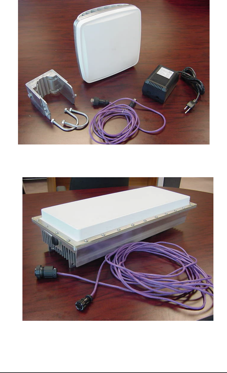
3-3
Figure 3-3-1: Subscriber Unit
Figure 3-2: Base Station Unit

TSUNAMI MULTIPOINT
3-4
Software Installation
1. Insert the CD provided into the Windows-compatible PC that you intend to use for all unit
configuration activities
2. Close all applications on the computer
3. Open CD file folders and open the folder named “jdk122”
4. Locate the “win9x” folder and open this folder
5. Identify the file called “jdk-1_2_2_005-win.exe” with the icon that typically looks like this
and double-click to launch installation of the Java Developers Kit
6. Follow the installation prompts. Do not change the path or options that are provided as
default settings (say ‘yes’ or ‘next’ to all prompts)
7. Edit your autoexec.bat file to include the statement:
“SET PATH=%PATH%;C:\jdk1.2.2\bin”
If you are unclear on how to modify your autoexec.bat file, follow this procedure:
8. Locate the existing autoexec.bat file on your C drive (this is normally in the root directory
of the C drive)
9. Copy this file to another location (such as in a folder or on your desktop)
10. Rename the copy to a new name (such as autoexec.old)
11. Initiate text editor program, such as WordPad
12. Open C:\autoexec.bat file using the text editor program
13. Scroll to the end of the file and add a line with the “set path” command line from above
14. Save and close the file – the file must be saved with the existing name and extension
15. Restart your computer
16. Close all applications on the computer
17. Open CD file folders and open the folder named “Ethernet Console”
18. Identify the file called “setup.exe” and double-click to launch installation of the Ethernet
Console program
19. Follow the installation prompts. Do not change the path or options that are provided as
default settings (say ‘yes’ or ‘next” to all prompts)
20. When completed verify that the Ethernet Console icon (shortcut) is located on your PC
desktop
21. Double-click on Ethernet Console icon. Wait approximately 20 seconds. The screen will
normally flash at first, then wait, then open the window permanently after several seconds.
If Ethernet Console does not launch properly, use “remove programs” utility to remove all
existing Java-related programs (including the one just installed). Repeat steps 3 through 6,
restart your computer, and repeat this step to initiate Ethernet Console. In most cases, this
process will overcome any issues with this program.
22. Delete copy of old autoexec file (if desired)
23. Remove CD
24. Installation is complete
TSUNAMI MULTIPOINT
3-5
Hub Site Equipment Configuration (BSU)
a. Initiate your PC’s IP address to 192.168.20.xxx (where xxx is anything other
than 120)
b. Set Subnet Mask on your PC to 255.255.255.0
c. Restart your PC if required
d. Initiate Ethernet Console on your PC by double-clicking on this icon
that appears on your PC desktop
e. Connect a straight CAT5 cable between your PC and the BS
f. Connect the BSU to the power supply via the cable provided
MAKE SURE POWER SWITCH ON THE POWER SUPPLY IS SET TO THE
OFF POSITION!
Connect the BSU power cord to 115Vac, 60 Hz power
ALL CABLES MUST BE CONNECTED BEFORE POWER IS TURNED ON!
IF NECESSARY, TURN TOGGLE SWITCH TO THE OFF POSITION
BEFORE DISCONNECTING CABLE BETWEEN BSU AND POWER
SUPPLY
Turn power supply on with toggle switch located on the power supply
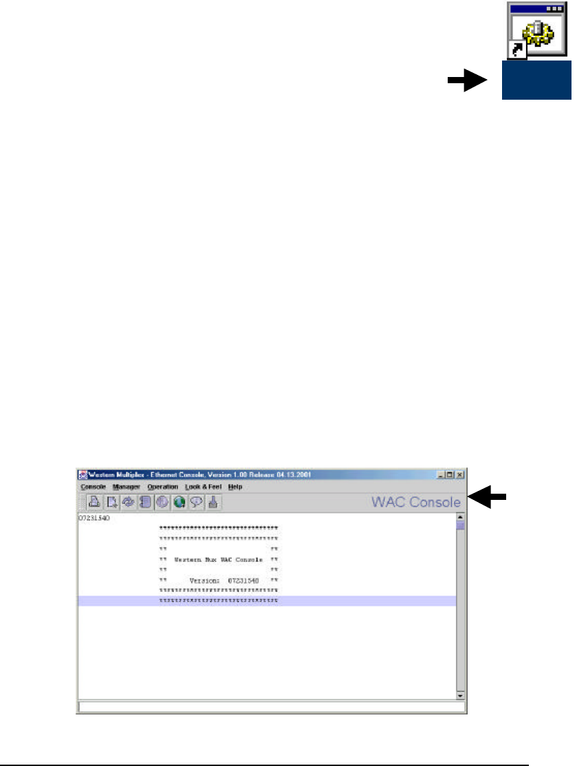
Wait approximately 10 seconds…. Watch the Ethernet Console for the initiation
screen shown below.
(The upper right corner of the Ethernet Console window changes from “Ethernet
Console” to “BSU Console” as shown below.)
Ethernet
Console

TSUNAMI MULTIPOINT
3-6
If “BSU Console” appears, but wakeup screen is not present – type “version” (return)
– you should see the screen above.
If “Ethernet Console” does not change to “BSU Console” after 30 seconds – recycle
the power using the toggle switch on the power supply. Try several times if needed.
§ Type “pa 255” (return) – this sets the unit’s output power to “on” using ALC
§ Type “pa” (return) to make sure pa command was received – screen should show
“Current_TXDAC= 160”
§ Type “pa 0” (return) to turn the transmitter power off.
§ The default IP address of the BSU is 192.168.20.120. To set the unit’s IP address, type “ip
xxx.xxx.xxx.xxx” (return)
§ If necessary, change your PC’s IP address to match the new numbering scheme
§ Reinitiate the Ethernet Console program if necessary.
§ After reestablishing communications (if this was necessary), type “ip” (return) to verify
new the new IP address.
§ The default subnet mask of the BSU is 255.255.255.0 (-1.-1.-1.0 in signed integer form).
To change the subnet mask of the unit, type “netmask xxx.xxx.xxx.xxx” (return)
§ This version of software does not provide direct verification of the subnet mask. You may
type “netmask” (return) to view the current subnet mask setting, however the number
provided is in degrees format (signed integer equivalent to hexidecimal) instead of
hexidecimal or decimal.
§ The default gateway of the BSU is 192.168.20.201. To change the gateway address for the
unit, type “gateway xxx.xxx.xxx.xxx” (return)
§ To verify gateway address for the unit, type “gateway” (return)
§ The default setting of the BSU for bandwidth modes is QPSK ½ (20 Mbps), also known as
modulation mode 3. To change bandwidth mode to QPSK ¾ (30 Mbps), type “modulation
2” (return) and then type “setconf” (return) to activate this setting. If you wish to return to
QPSK ½ (20 Mbps) mode, type “modulation 3” (return) and then type “setconf” (return).
§ To verify bandwidth (modulation) mo de, type “modulation” (return)
§ The default setting of the BSU for uplink and downlink time slot allocation is 5 time slots
downlink and 3 slots uplink (corresponding to the 20 Mbps bandwidth mode, which has 8
total time slots). To change these settings, type “firstInboundSlot x” (return) and then type
“setconf” (return). In the 20Mbps bandwidth mode (modulation mode 3), the lowest
number for this setting is 2 and the highest is 5. In the 30 Mbps bandwidth mode
(modulation mode 2), the lowest number for this setting is 2 and the highest is 9.
§ To verify the uplink and downlink time slot allocations, type “firstInboundSlot” (enter)
§ Helpful hint: The number “x” within the statement “firstInboundSlot x” is equivalent to
the total number of downlink timeslots that are allocated (zero through ‘first inbound slot’
minus 1).
§ The default setting of the BSU channel frequency is 3. There are four operating channel
frequencies in this model. To change the frequency channel of the BS, type “frequency x”
(return), then type “setconf” (return). Valid numbers are 0 through 3.

TSUNAMI MULTIPOINT
3-7
§ To verify the frequency channel, type “frequency” (enter).
§ At any time, if you wish to return a unit to the factory default settings, you may type
“restart” (return) or cycle power (using the toggle switch on the power supply). It is
advised to use the restart command.

TSUNAMI MULTIPOINT
3-8
Subscriber Unit Configuration
The CPE units require the same software and are connected and controlled in an
identical fashion as the BS. Configure the BSU unit and your computer first to
become familiar with these connections and controls and to be ready to connect to the
CPE.
§ CONNECT ALL CABLES BEFORE PLUGGING INTO AC POWER
§ DISCONNECT AC POWER FIRST BEFORE REMOVING THE CABLE BETWEEN
THE POWER SUPPLY AND CPE
ONLY THEN APPLY 115VAC 60 Hz POWER
When your PC is connected to a CPE unit, the Ethernet Console will display “SU
Console” (instead of BSU Console) in the upper right corner of the screen.
Use the IP, gateway and subnet mask commands to change or verify these settings for
each CPE unit. No other commands should be needed. The CPE will automatically
detect proper operating frequency and bandwidth settings.
It can be helpful to configure the CPE equipment before it establishes a link with the
BS. When RF communication is initiated, the units will start negotiating and
registering IP addresses, setting frequency channels and other settings. The terminal
number of the CPE is labeled on the bottom of the CPE, and this number (along with
IP address and Ethernet address) will appear on the BSU console screen when the
CPE is negotiating with the BSU for initialization.
When a link is established, both ends of the system will display different
communications on the Console window. The signal strength can be seen on the SU
Console, and this can be used as a rough antenna alignment tool. The command to
view signal strength is “rsl” (return). To align antennas, align by sight, type “rsl”
(return) in the SU console, read the RSL, make fine adjustments to the antenna
alignment, and type “rsl” (return) again, repeating until signal is peaked. The number
returned by the rsl command is in dBm, therefore, the less negative the number, the
stronger the signal (such as –40 is higher than –50).
TSUNAMI MULTIPOINT
3-9
Mechanical Considerations – Mounting Units
The CPE units are designed to directly mount to 1-1/2 inch to 1-3/4 inch pole
diameters (outer diameter), or mount to pole diameter of 2 inches or to a wall or other
flat surface using optional mounting brackets.
For mounting directly to a 1-1/2 inch or 1-3/4 inch pipe, first attach the mounting
bracket to the pole using the U-bolt retainer. Then attach the SU to the mounting
bracket, and lock into position by tightening the 10-32 screws. See photos below for
detail. Connect the weatherproof RJ45 connector.
For mounting to a flat surface, attach mounting bracket to the CPE using bolts
supplied, and then mount to flat surface using your own hardware.
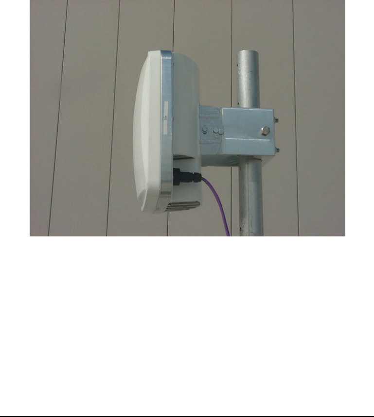
Figure 3-2 Subscriber ODU
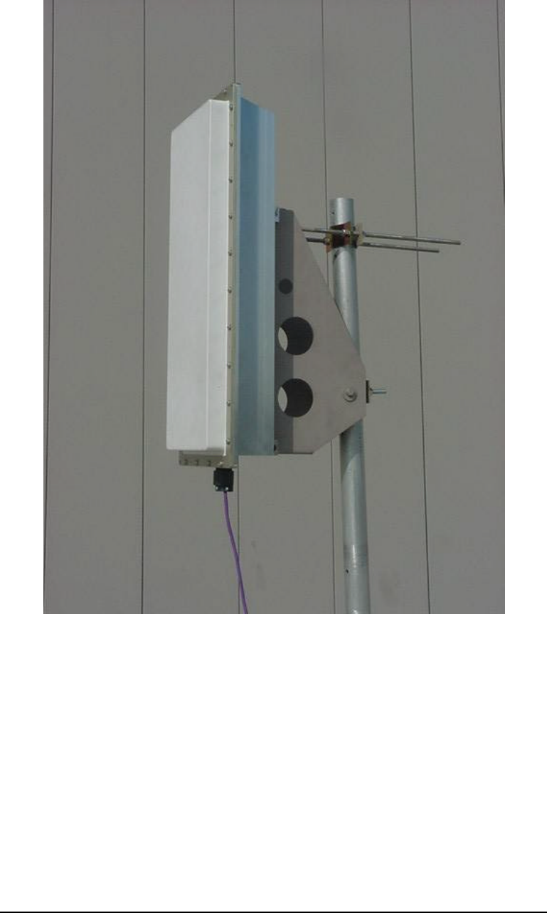
The BSU is designed to mount to a 2 inch to 2-3/4 inch pipe using the bracket and
hardware supplied. See photos below for detail.
TSUNAMI MULTIPOINT
3-10
Figure 3-3: Base Station ODU

DESIGN CUSTOMIZATION
4. Specifications
PRODUCT MODEL MODEL NUMBER
Base Station Unit 60 Mbps 40400-605
20 Mbps 40400-205
Subscriber Unit 60 Mbps 40100-605
40 Mbps 40100-405
20 Mbps 40100-205
SPECIFICATION SPEED OPTIONS
Aggregate throughput 60 Mbps 20, 40, 60 Mbps
40 Mbps 20, 40 Mbps
20 Mbps 20 Mbps
SPECIFICATION SPEED Rx Tx
Threshold – Base Station 40, 60 Mbps -77 dBm 36 dBm
20 Mbps -89 dBm 36 dBm
Threshold – Subscriber Unit 60 Mbps -77 dBm 36 dBm
40 Mbps -81 dBm 36 dBm
20 Mbps -89 dBm 36 dBm
Maximum Distance 60 Mbps at 5 miles/8 kilometers
40 Mbps at 6 miles/10 kilometers
30 Mbps at 7 miles/11 kilometers
20 Mbps at 8 miles/13 kilometers
SYSTEM
Operating Frequency Range 5725-5825 MHz
Radio Access Method TDMA
Duplexing Time Division Duplex (TDD)
Integrated Antenna
Base Station Unit (BSU) 18 dBi (60 x 6)
Chapter
4

TSUNAMI MULTIPOINT
4-12
Subscriber Unit(SU) 21 dBi (10)
Max Subscriber Units/BSU 1,024
Distance/Capacity Limits 60 Mbps at 5 miles/8 kilometers
40 Mbps at 6 miles/10 kilometers
30 Mbps at 7 mi les/1 1 kilometers
20 Mbps at 8 mi les/1 3 kilometers
Frequency Channels 4 non-overlapping, 6 available
Regulatory Compliance FCC Part 15.400 (U-NII)
IC RSS21 0
STANDARDS COMPL LANCE AND INTERFACES
Ethernet Interface 10/10OBaseT
Ethernet Connector RJ45 female
SU indoor-outdoor cable RJ45 (outdoor) & DIN(indoor)
over Category-5 cable
BSU indoor-outdoor cable Circular plastic connectors
over Category-5 cable
Standards Compliance IEEE 802.1d Bridging Mode
IEEE 802.1 1q VLAN
IEEE 802.16b Broadband
Wireless Access
CONFIGURATION AND MANAGEMENT
Base Station Configuration via Ethernet, SNMP, or Wireless Manager
Subscriber Unit Configuration Automatic
SNMP Agent MIB 11
Security Authentication, IP/MAC
Filtering
Software Upgrades Over-the-air Subscriber Unit reprogramming
Downloadable Base Station reprogramming
POWER /ENVIRONMENT /SAFETY
Electrical
Base Station Unit -36 to -60 Volts DC, 1.25 Amps
Subscriber Unit 18 to 28 Volts DC, 0. 8 Amps
Subscriber Unit Power Brick 115 Volts AC
Base Station Unit Power Brick 100-240 Volts AC
Base Station Unit Power Block -48 Volts DC
Operational Temperature -40º to 55º C (all units)
Humidity 5% to 100%, condensing
EIVIC FCC Class B
Safety UL-1950

TSUNAMI MULTIPOINT
4-13
Environmental Compliance ETS 300 019
PHYSICAL DIMENSIONS
Subscriber Unit (Outdoor Unit)
Size (WxHxD) 1O.5x10.5x 6.8 inch/126.5x26.5x 17.4cm
Weight 10 lbs/ 4.5 kg
Subscriber Unit Power Brick (Indoor Unit)
Size (WxHxD) 3.6 x 5.1 x 2.6 inches/92 x 130 x 67 cm
Weight 2.7 lbs/1.2 kg
Base Station (Outdoor Unit)
Size (WxHxD) 10.2 x 24 x 6.6 inches/25.9 x 61 x 16.8cm
Weight 20 lbs/9 kg
Base Station Power Block (Indoor Unit, for up to 6 Base Stations)
Size (WxHxD) 17.2 x 3.5 x 8.25 inches/43.7x8.9x 21cm
Weight 5 lbs/2.3 kg
Base Station Power Brick (Indoor Unit, for 1 Base Station)
Size (WxHxD) 37.4x 70.9 x 24.8 inch/95 x 180 x 63 cm
Weight 1.5 lbs/0.7 kg
MOUNTING (INSTALLATION)
Base Unit Pole Mount, 1.75-2.75" dia.
Subscriber Unit Pole Mount, 1.25-2.75" dia.
(wall mount kit available)