Proxim Wireless US58-B60 U-NII/Spread spectrum radio User Manual SS BSU Manual v001d1SS
Proxim Wireless Corporation U-NII/Spread spectrum radio SS BSU Manual v001d1SS
UserManual.wiki
>
Proxim Wireless
>
US58 B60 User Manual
Installation Manual
Navigation menu
Upload a User Manual
Namespaces
Wiki Guide
HTML
PDF
Info
Views
User Manual
Discussion / Help
Navigation


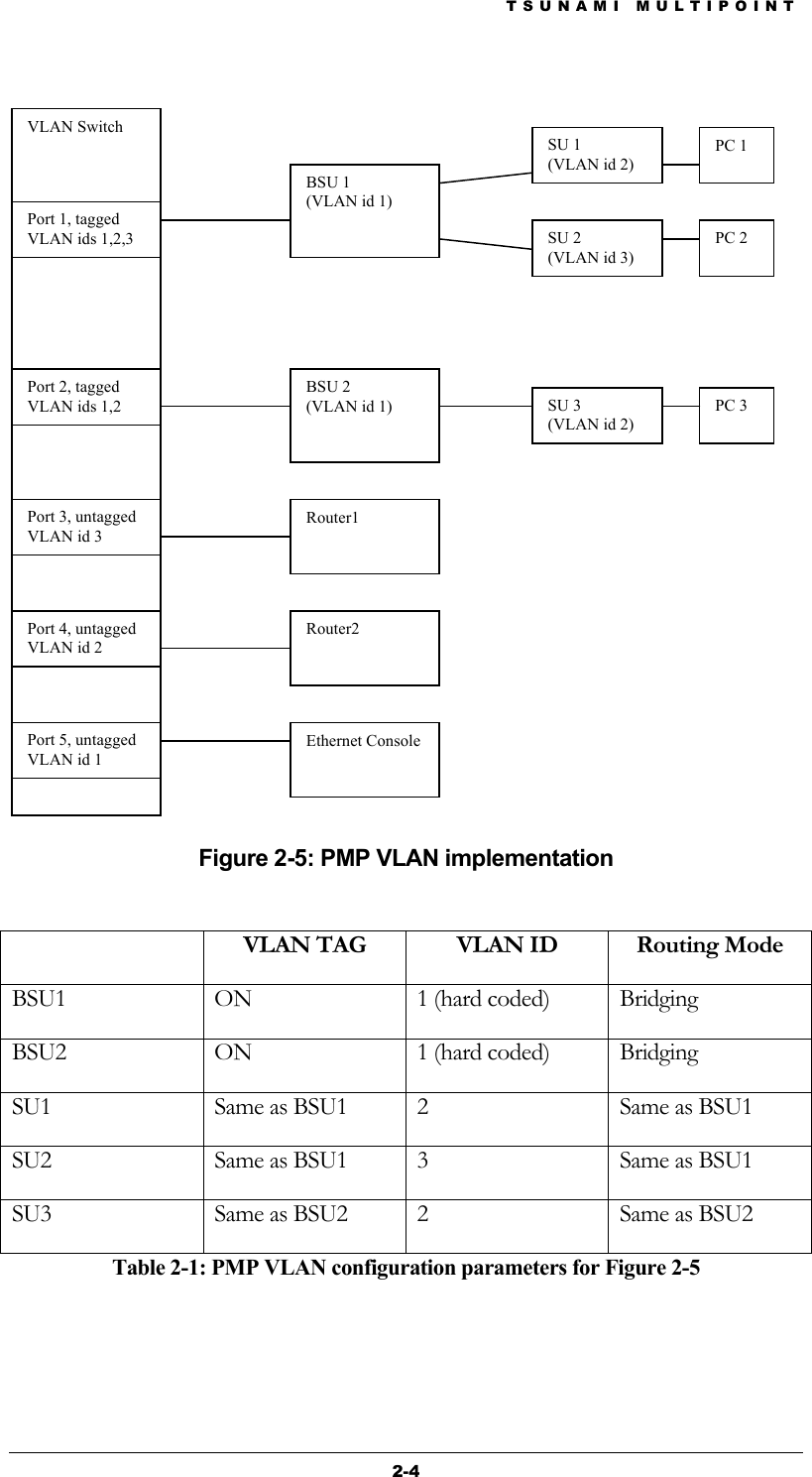
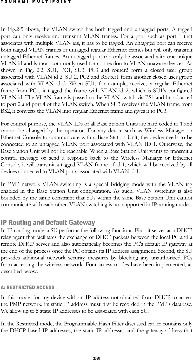
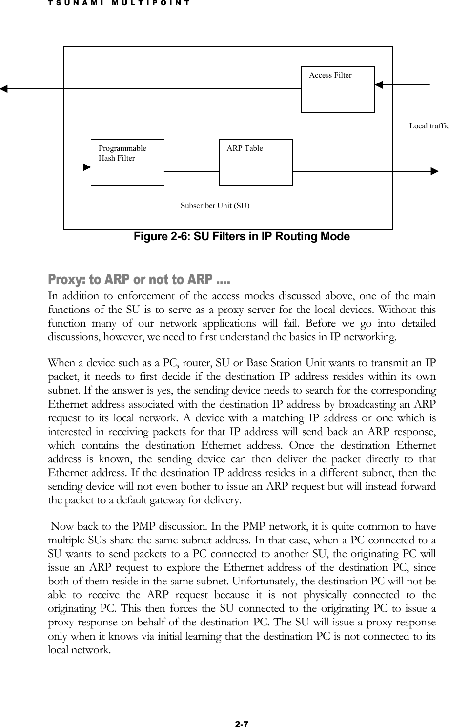
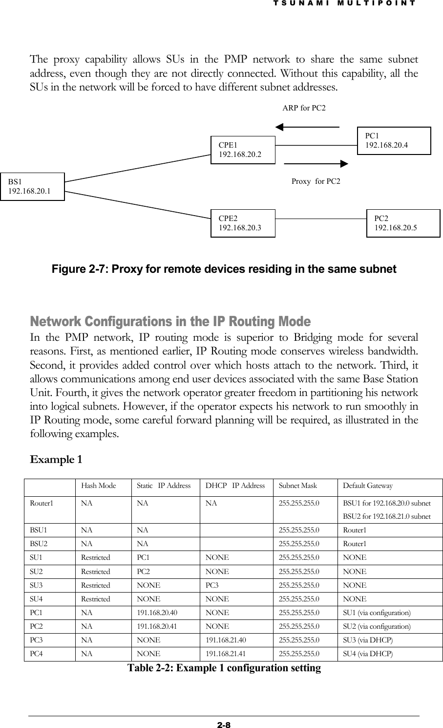
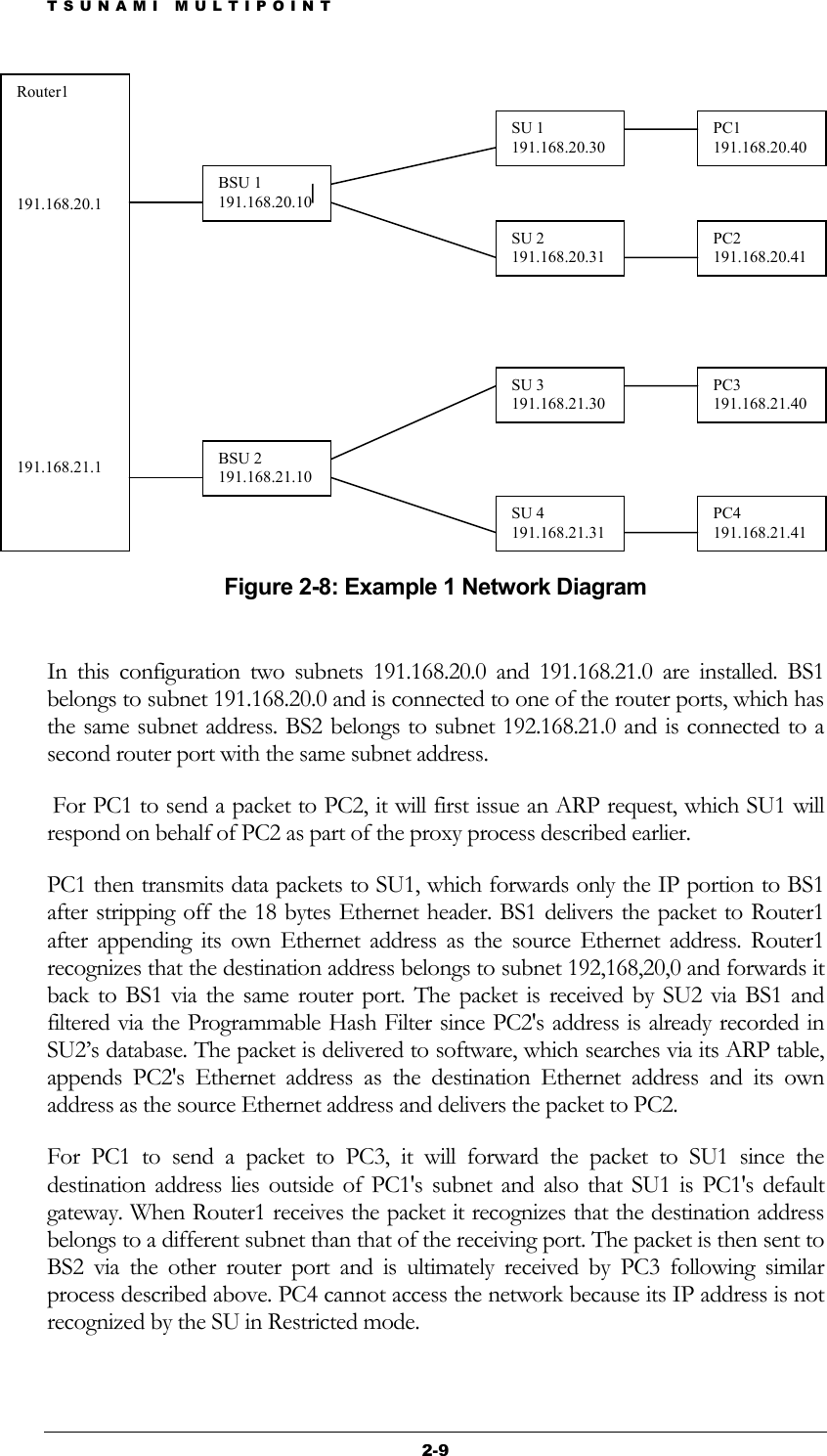
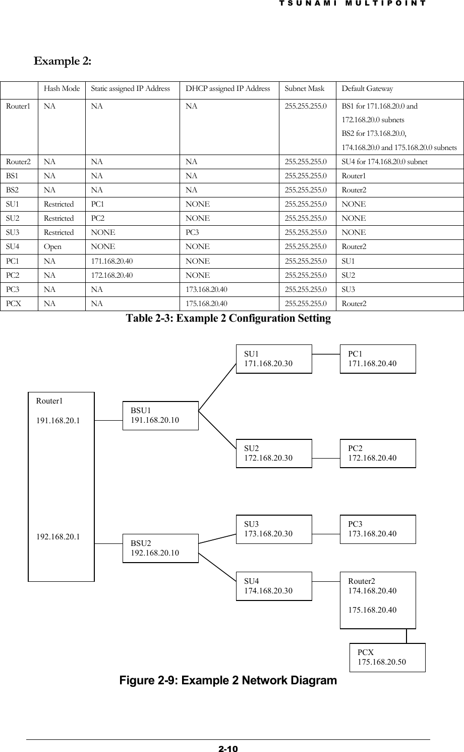


![TSUNAMI MULTIPOINT 5-2 Command to assign the number of reserved aloha channels Command: aloha <aloha channels> Example: aloha 1 Comment: At least one aloha channel must be assigned. The number of aloha channels cannot exceed 15. Warning: This command will force the Base Station to reset automatically and come up with the new configuration Command to change the routing mode Command: routingMode <mode> Example: routingMode 0 Comment: The mode should be set to 0 for IP routing and 1 for bridging. Warning: When the Base Station senses the routing mode has changed, it will restart and come up with the new routing mode and force all the SUs in its sector to restart. Command to turn the VLAN tagging on or off Command: setVLANTag <tag> Example: setVLANTag 0 Comment: Set the tag to 0 to turn VLAN tagging off and 1 to turn VLAN tagging on. VLAN tagging will take effect only in bridging mode Command to display the Base Station's configuration settings Command: dspconf Comment: If dspconf ? is entered, all the available configuration commands and their syntax will be displayed Command to change the Base Station’s IP address Command: setIP [IP address] Example: setIP 192.168.20.10 Command: The Base Station console will display the Base Station’s current IP address, if no IP address is entered. Command to change the Base Station’s gateway IP address Command: gateway <gateway address> Example: gateway 192.168.20.11 Command: The Base Station console will display the Base Station’s current gateway address if no gateway address is entered.](https://usermanual.wiki/Proxim-Wireless/US58-B60/User-Guide-242211-Page-59.png)