Psiber Data Systems Wifi Planner Rf3D Users Manual
RF3D to the manual a072621f-5f70-4e85-82f4-b34f28d4abab
2015-02-06
: Psiber-Data-Systems Psiber-Data-Systems-Wifi-Planner-Rf3D-Users-Manual-521110 psiber-data-systems-wifi-planner-rf3d-users-manual-521110 psiber-data-systems pdf
Open the PDF directly: View PDF ![]() .
.
Page Count: 47
manual
1
®
manual
for RF3D WifiPlanner and
RF3D WifiPlanner Lite

manual
1
Contents
1 Introduction 2
1.1 PC 1.1PC Hardware Requirements 3
1.2 Installation and Activation 3
1.3 Product Updates 5
2 Fundamentals of Wireless Network Planning 5
2.1 Standardization in Wireless Networking 5
2.1.1 The IEEE 802.11b Specification 5
2.1.2 The IEEE 802.11g Specification 6
2.1.3 The IEEE 802.11a Specification 6
2.1.4 The IEEE 802.11h Specification 6
2.2 Frequencies and Channels 6
2.3 Cellular Structure of a Wireless Network 8
2.4 Antennas 9
2.4.1 Omnidirectional Antennas 10
2.4.2 Patch Antennas 10
2.4.3 Yagi Antennas 10
2.5 Attenuation 10
2.6 Theoretical Throughput Rates 10
2.7 Redundancy 11
3 The RF3D User Interface 11
3.1 Importing Building Plans 11
3.2 The Toolbox 14
3.3 Drawing and Selecting Elements 15
3.4 The Simulation Tab 15
3.5 The Access Point Tab 17
3.6 Advanced Settings 17
4 Planning Wireless Networks 17
4.1 What Application Is Intended? 17
4.2 Entering Environmental Factors 18
4.3 Positioning Access Points 19
4.4 Optimizing Wireless Networks 21
5 Advanced Settings 22
5.1 Editing Wall and Floor Libraries 22
5.2 Editing the Access Point/Antenna Library 23
5.3 Options and Settings 27
5.4 Floors with Openings 27
5.5 Split-Level Buildings 28
Appendix A The Antenna Library 29
Appendix B The Wall and Floor Library 35
Appendix C Table of Colors 38
Appendix D EULA 40

manual
2
1 Introduction
Thank you very much for choosing RF3D WifiPlanner! RF3D WifiPlanner is an advanced
program for planning wireless networks in conformance with the IEEE 802.11a/b/g/h
standards. RF3D WifiPlanner helps you design more efficient wireless networks and en-
sure that they deliver optimum service even under heavy loads. Such planning usually
saves costs too, not least by eliminating unnecessary access points. This also means
less radiation, which is another benefit that should not be underestimated.
The number of wireless networks in professional use is constantly growing. For compa-
nies that want full WiFi coverage using multiple access points, there is no substitute for
professional and efficient planning. Until now, however, it has been difficult to optimize
the time and money spent on planning robust, high-availability wireless networks, es-
pecially in multi-story buildings. RF3D WifiPlanner software by Psiber Data meets this
need, providing economical, application-specific planning of both simple and com-
plex wireless networks.
RF3D WifiPlanner provides true three-dimensional simulation of radio signal distribu-
tion in the building, and is thus the first tool to visualize co-channel and next-channel
interference from access points on other floors. Furthermore, the number of access
points required can be easily optimized through on-screen interactive planning. And
this planning software pays for itself with the first unnecessary access point you save.
Wireless network planners usually provide for too many access points, and more ac-
cess points do not generally improve the network quality. Instead, they cause channel
overlap, which is often unavoidable, especially in 2.4 GHz networks. As a result, com-
plex wireless networks are usually relatively error-free at low data rates, but as data
rates increase, errors become more frequent. But RF3D WifiPlanner lets you optimize
your network specifically for the use you anticipate.
RF3D WifiPlanner uses theoretical principles to calculate signal distribution. The net-
work as installed and its actual coverage may deviate from the results of such cal-
culations. Because the calculations are based on theoretical values, Psiber Data as-
sumes no liability for the accuracy of the results.
manual
3
1.1 PC 1.1PC Hardware Requirements
• Processor: Intel Pentium, 1.5 GHz or faster
• Display: 1024×768 or greater
• RAM: 750 MB for networks with less than 30 access points.
For larger network plans, 1 GB or more.
1.2 Installation and Activation
Before installing the software, please open Add or Remove Programs under Start / Con-
trol Panel, and verify that the Microsoft .NET Framework 2.0 (or higher) has been in-
stalled on your computer. If it is not already installed, please download the Microsoft
.NET Framework from www.microsoft.com and install it before you continue.
Furthermore, make sure that you have Administrator privileges on your PC and a work-
ing connection to the Internet.
Insert the installation CD into your drive. If the installer does not start automatically, dou-
ble-click the installation file to start it.
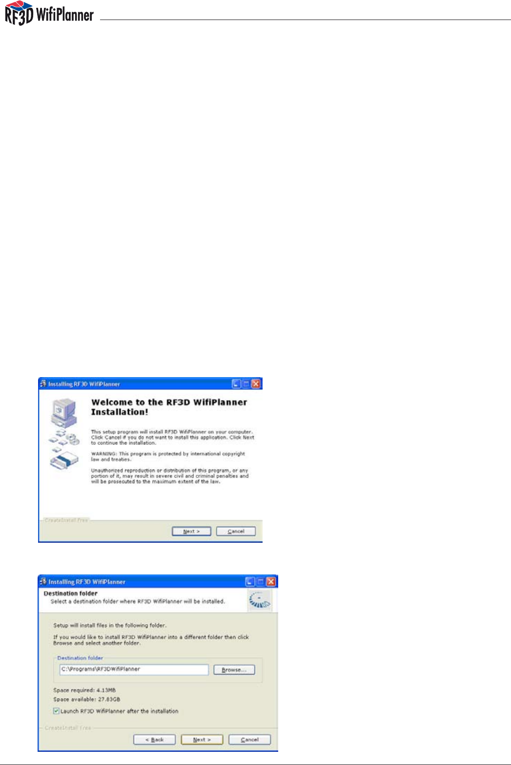
After starting the installer, you will see the welcome message.
Click Next
manual
4
Now choose the installation folder for the program. We recommend using the default
directory path. Please do not change the name of the application folder, “RF3DWifi-
Planner”. Click Next and wait for the installation to be completed.
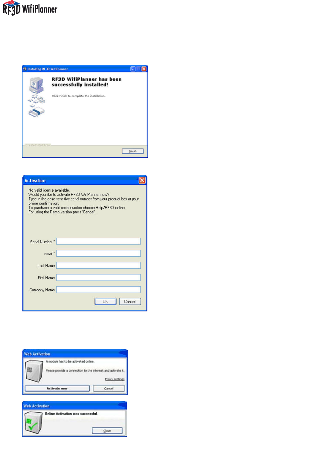
After you click Finish, RF3D starts and displays a license activation dialog:
If you would like to evaluate the software in demo mode, simply click Cancel. Otherwise,
enter the serial number from your CD box or online purchase confirmation, your name, the
name of your company, and your e-mail address. Click OK. The following dialog appears:
For the next step, please make sure that the com-
puter is connected to the Internet. After you have
successfully activated the software, you will see
the following dialog:
Click Close to conclude the installation and activation, and start working with your
RF3D WifiPlanner.

manual
5
1.3 Product Updates
New versions of RF3D WifiPlanner are released from time to time. To search for up-
dates, please visit www.rf3d.com in the Internet. The RF3D website has a download
area where you can download the latest program version.
The same website allows you to upgrade from RF3D WifiPlanner Lite to the next higher
version. Or you can order an upgrade by e-mail to sales@rf3d.com.
Fundamentals of Wireless Network Planning
To plan an efficient wireless network, it helps to understand a little radio communica-
tion theory. In this document we can only provide a brief summary with regard to wire-
less networks. For more detailed information, please consult the specialist literature.
2.1 Standardization in Wireless Networking
In designing standards for wireless networks as they are used in the industry today, the
IEEE built on the Ethernet standard, IEEE 802.3. Like Ethernet, an IEEE WLAN functions
as a shared medium with a decentralized access control mechanism. Every station
competes for access with all other stations, and is responsible for regulating its own
use of the medium. In this situation, the CSMA/CD access protocol (Carrier Sense Mul-
tiple Access with Collision Detection) ensures that every station gets an opportunity
to transmit data over the medium. Because it uses the same media access technique,
802.11 WLAN is often called “wireless Ethernet”.
The IEEE 802.11 standard defines several different Ethernet-based wireless networks.
The most common of these are 802.11a, b, g and h. In general, two different radio
techniques are used in two different frequency bands. The 2.4 GHz ISM band is most
often used. This band is reserved worldwide for license-free industrial, scientific and
medical applications. The frequency band used can vary from one country to an-
other, however. For example, eleven channels can be used in the 2.4 GHz band in the
United states, while up to 14 channels are available in other parts of the world. The
other frequency band used for wireless Ethernet is around 5 GHz. In addition to the fre-
quency bands, the IEEE standards also specify transmitter power, data rates, packet
structure, management packets, and much more.
2.1.1 The IEEE 802.11b Specification
The wireless Ethernet standard IEEE 802.11b, adopted in late 1999, is the first such
standard to be widely supported for both industrial and home use. Networking com-
ponents that support this standard communicate in the 2.4 GHz band. The specified
data transfer rates are 1, 2, 5.5 and 11 Mbit/s.

manual
6
2.1.2 The IEEE 802.11g Specification
The IEEE 802.11g wireless Ethernet specification is an advanced extension of the wide-
ly accepted 802.11b standard, and was adopted in mid-2003. Like its predecessor,
802.11g also uses the 2.4 GHz frequency band. The data transfer rates were substan-
tially increased, however, so that the 802.11g standard permits throughput of 1, 2, 6, 9,
12, 18, 24, 36 and 54 Mbit/s. Networking components that conform to the g specica-
tion are also compatible with the earlier b standard. For this reason, such components
are often designated as “802.11 b/g compatible”.
2.1.3 The IEEE 802.11a Specification
The 802.11a extension to the IEEE wireless Ethernet standard was adopted in late 1999.
Unlike b and g networks, 802.11a uses the 5 GHz band. The advantage here is that
channel overlap is less frequent. The drawback, however, is that the 5 GHz band is
subject to various regulations and restrictions in some countries. Like the g standard,
802.11a species throughput rates of 1, 2, 6, 9, 12, 18, 24, 36 and 54 Mbit/s.
2.1.4 The IEEE 802.11h Specification
Although IEEE 802.11b equipment became widespread all over the world around
the turn of the millennium, the market for IEEE 802.11a products developed relatively
slowly. In some countries, the regulatory agencies had not yet approved public use of
the frequency band. The IEEE 802.11h extension was a substantial prerequisite to the
use of products in conformance with the a standard in Europe. One major innovation
of the h specification is that components monitor the desired channel for other appli-
cations, such as radar, which could otherwise be impaired by wireless network opera-
tion. In case of such interference, the WLAN equipment either reduces its transmitter
power or shuts down. The operator can then select a different channel.
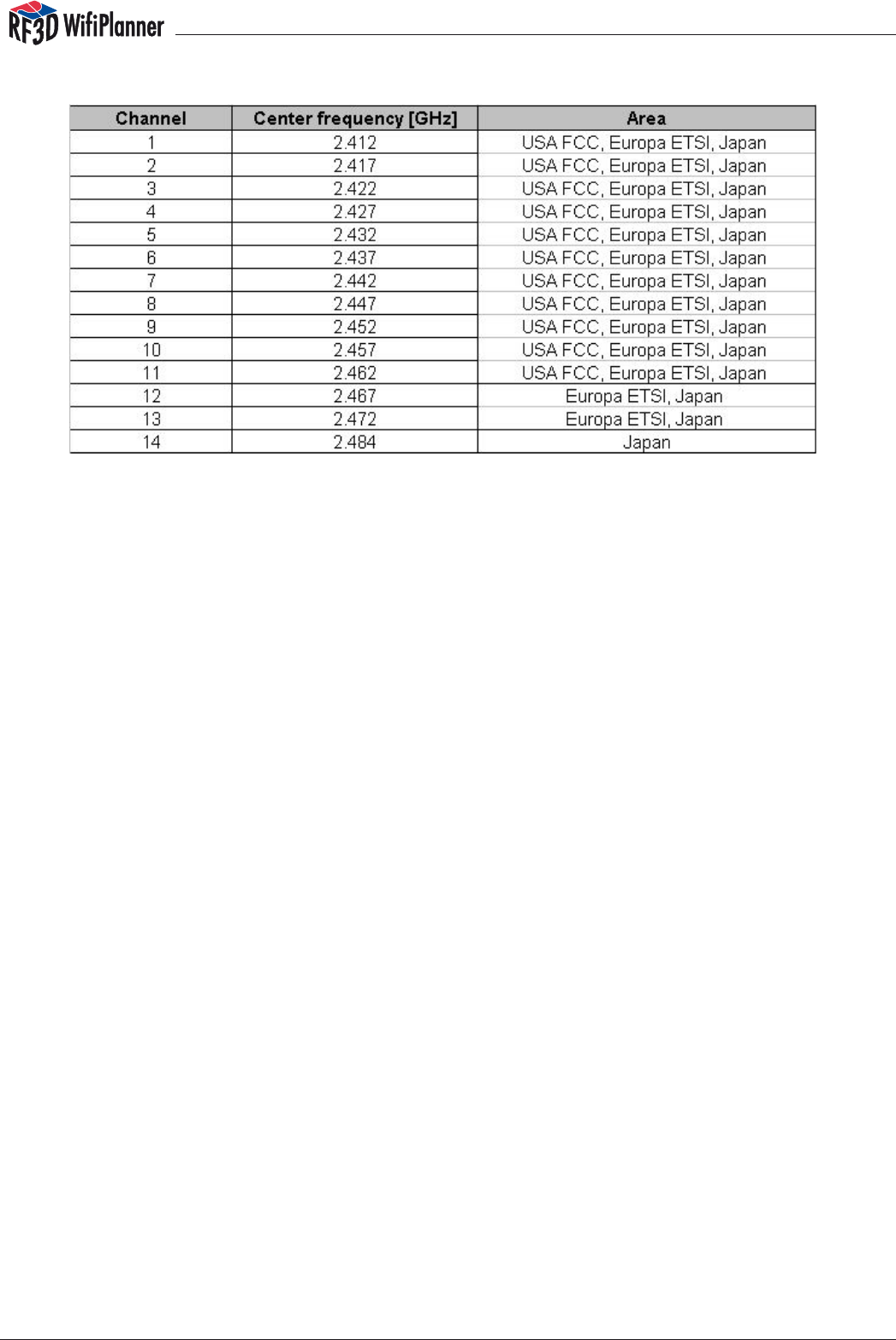
2.2 Frequencies and Channels
All the wireless standards described here work with fixed channel settings, not with
“frequency hopping” as used by other technologies such as Bluetooth. The 2.4 GHz
ISM band is divided into 14 channels. Channels and frequencies are subject to dif-
ferent local regulations in each country, however, which must be taken into account
during planning. For example, in the US, only channels 1 to 11 are used, while in Europe
channels 1 to 13 are available. It is generally up to the operator to ensure that local
regulations are observed.
manual
7
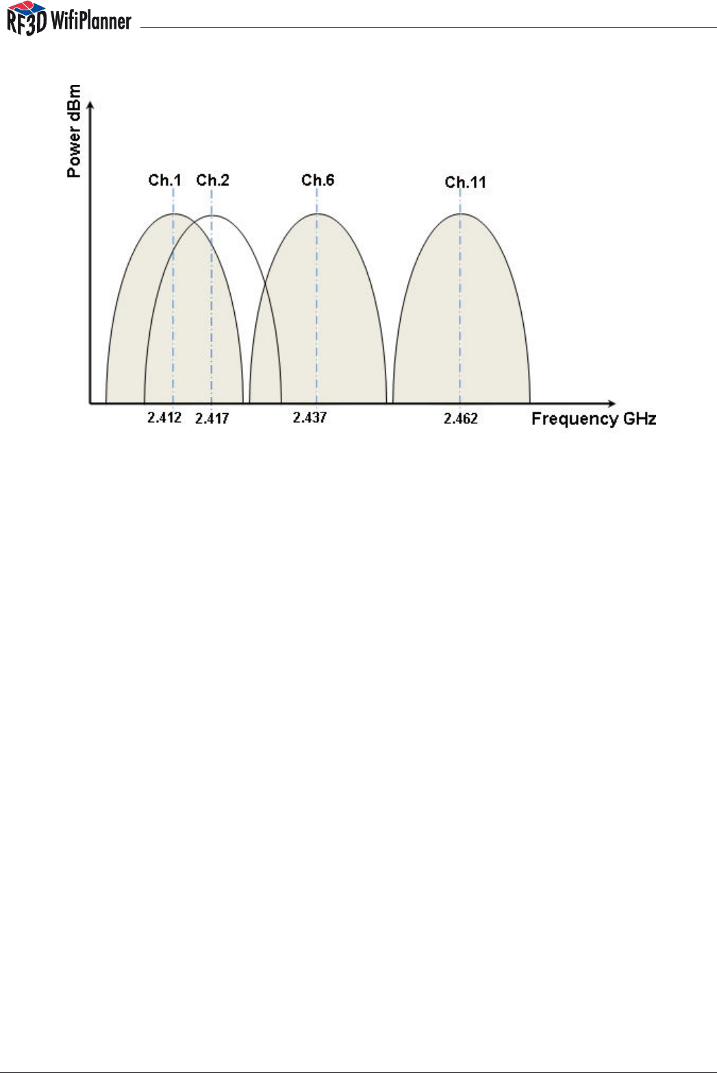
However, the channels in the ISM band overlap. For example, with reference to the
actual radio output of an access point, we find that an access point transmitting
on channel three also emits a signal on the neighboring channels 1, 2, 4, and 5. This
means that other WLAN components communicating on any of those four chan-
nels will receive interference. This happens whenever the components transmit data.
Data transmission generally occurs even when no user data is transported over the
network — in other words, when the network is idle — because management informa-
tion, beacons, keep-alive packets and the like still have to be transported at regular
intervals. This phenomenon is called near-channel interference.
manual
8
Interference arises whenever data is transmitted, and therefore networks that carry
little or no data generate less interference. This also means that, although a network
with lower data traffic still functions in spite of channel overlap, problems can be ex-
pected as traffic increases. In planning, of course, attention must be given to avoiding
channel overlaps. This is done by planning overall WLAN network as a cellular structure
in which adjacent cells use channels that are far apart in the frequency spectrum.
Among the eleven channels available in the US, no more than three can be used with
no overlapping: channels 1, 6, and 11.
It is also helpful to know that the maximum permissible transmitter power in this ISM
band for indoor use is 20 dBm, or 100 mW.
The 5 GHz frequency band offers a greater number of non-overlapping channels, but
is often subject to national regulations. Different countries permit different maximum
indoor and outdoor transmitter power levels, for example.
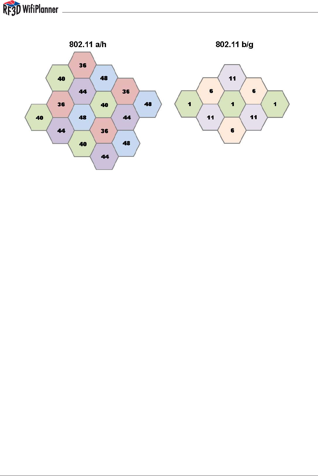
2.3 Cellular Structure of a Wireless Network
The size of a wireless cell — that is, the coverage area of an access point — is limited
by the transmitter power. To cover larger areas, a structure of several adjacent cells is
recommended. Because the adjacent cells overlap spatially, they must use distinct,
non-overlapping channels.
manual
9
Note that, in this cellular structure, channel overlap must be avoided not only within
each floor of a building, but also between adjacent floors. In other words, access points
above and below one another should not use the same channels.
Another important consideration is the security of a company-wide wireless network.
Usually the operator wants to avoid WLAN transmission beyond the boundaries of the
company’s premises in order to prevent unauthorized access from outside. Furthermore,
in designing the network’s cellular structure, you should also consider what applications
are to be transported over the network. If an application such as telephony is to be pro-
vided over the WLAN, then each cell — that is, each access point — is usually supposed
to support a specific number of simultaneous calls. This is usually not feasible in cells of
the greatest possible size, so the network should be designed with smaller cells. Smaller
cells can be achieved by reducing the transmitter power of specific access points. In
this case, of course, more access points are required to cover a given area.
Another consideration in planning wireless cells is that the data rate depends in part
on the signal power received at any given point. For applications with low data traffic,
such as warehouse or logistics applications, it can be efficient to use the outer fringes
of a cell in spite of weaker signal power.
2.4 Antennas
Antenna technology would take up a full chapter in a survey of WLAN fundamentals.
For planning purposes, you need to know that cell shapes can be optimized by using
appropriate antennas. In office floors, for example, signal radiation in a horizontal plane
is very important, while vertical radiation is often undesirable, since it causes interfer-
ence in the floors above and below. A highly directional antenna, such as a panel
antenna, may be used to cover a long corridor. Yagi antennas have an even narrower
beam and are used for point-to-point communications, such as radio links between
two buildings.
manual
10
2.4.1 Omnidirectional Antennas Omnidirectional antennas are generally used to in-
crease the communication range within offices or homes. The antennas commonly sup-
plied with access points are omnidirectional. Omnidirectional antennas have a beam
angle of 360° in the horizontal plane. Vertically, their radiation pattern is compressed, and
may cover an angle of 80°. These antennas can have a gain of 2 to 5 dB, and may be
used to increase an access point’s horizontal range.
Please see appendix A: The Antenna Library
2.4.2 Patch Antennas Patch antennas typically offer gain of 4 to 6 dB, with horizontal
and vertical beam angles of 80° to 65°. A patch antenna can increase the communica-
tion range by up to 100%.
2.4.3 Yagi Antennas Yagi antennas are extremely directional antennas, and are used
to set up point-to-point radio links, bridging distances of up to 300 m at 54 Mbit/s, 1 km
at 11 Mbit/s, or 2 km at 2 Mbit/s for example using 2.4 GHz WLAN. In this way separate
buildings can be interconnected using WLAN equipment.
Please see appendix A: The Antenna Library
2.5 Attenuation
Once the signal leaves the access point’s antenna, it is subject to attenuation, or loss: that
is, it becomes weaker. In the ideal case, the signal attenuation with increasing distance
from the antenna is called free-space loss. The theoretical rate of free space loss is different
for the different frequency bands, 2.4 GHz and 5 GHz. A 5 GHz signal is subject to greater
loss than a 2.4 GHz signal. Indoors, the actual attenuation depends on the given build-
ing. The signal loss through wooden walls is clearly different from the loss through stone or
reinforced concrete. It is therefore important to determine the building materials involved
and their specific properties.
Please see appendix B: The Wall and Floor Library
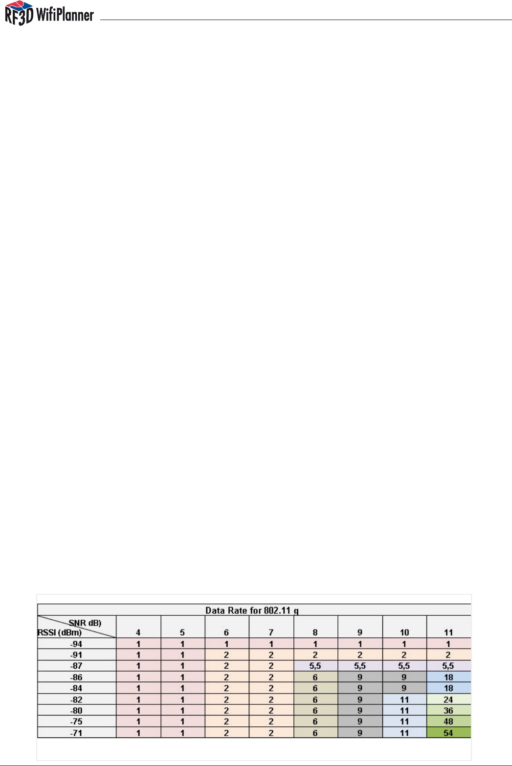
2.6 Theoretical Throughput Rates
Signal strength is one of the factors that determine the theoretical throughput of a wireless
LAN. Wireless LAN components lower their data rate automatically when the received signal
power is no longer sufficient for a higher throughput. Furthermore, the received signal must
also be greater than the noise due to interference, typically by 10 dB. Thus the signal quality
is characterized in terms of the signal-to-noise ratio (SNR).
manual
11
2.7 Redundancy
To protect the supported applications against failures, a certain redundancy must be de-
signed into a wireless network. This means that, if a given access point fails, the stations it
served can join neighboring radio cells. However, since access points too close together
generally cause interference, redundancy planning always involves a compromise between
reliability and throughput.
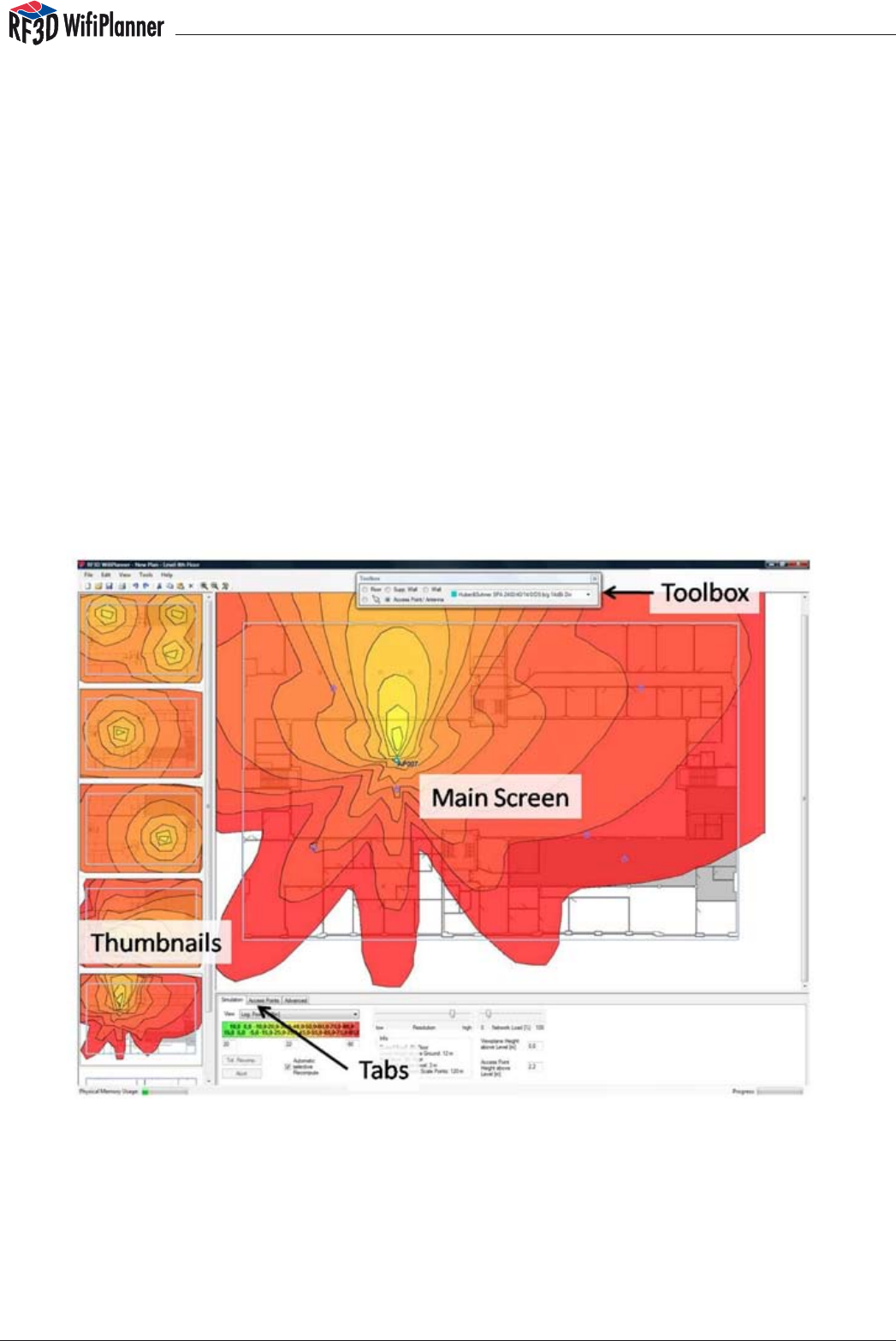
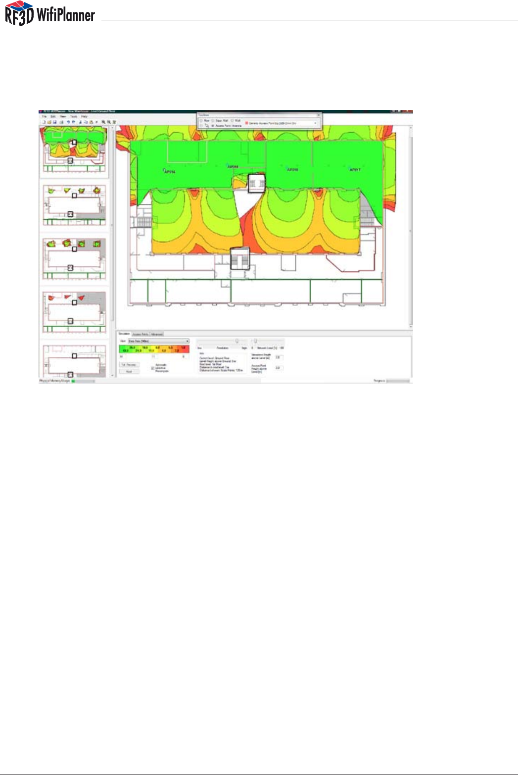
The RF3D User Interface
RF3D WifiPlanner’s user interface has been designed to display even complex WLAN plans
understandably. RF3D WifiPlanner calculates three-dimensional radio characteristics in real
time, and displays them in horizontal cross-sections corresponding to the floors of a build-
ing. A navigation column at the left presents simplified thumbnails of all the floor plans. The
selected floor is displayed in detail in the main window, where you can edit it interactively.
The tabs at the bottom of the window allow you to select the Simulation, Access Points and
Advanced options.
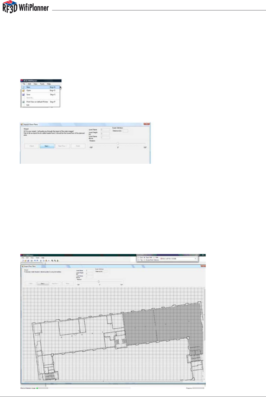
3.1Importing Building Plans
For an exact simulation of floors one above another, the building plans must be aligned. For
this purpose the RF3D WifiPlanner includes an Import Wizard to assist you in importing indi-
vidual floor plans in alignment with one another. Floor plans can be imported in the common
image formats JPG, BMP and PNG. In selecting oor plans, you should choose image les of
moderate size and resolution, since high-definition floor plans consume memory unnecessar-
ily. We recommend that you use images of less than 1000 × 1000 pixels. If your plans are cur-
manual
12
rently in DXF format (as produced by Auto-CAD for example), you can convert them either
using the graphics program they were created with, or using commonly available utilities.
Other ways of obtaining the necessary plans include scanning paper drawings or photo-
graphing the emergency exit plans posted on each floor of most buildings. It doesn’t matter
if the individual oor plans have different resolutions or orientations: the Import Wizard solves
such problems easily.
To start the Wizard, select the menu command File/New.
Click Next to import an image file of the first floor plan. Browse to the desired image
file in the file selection dialog.
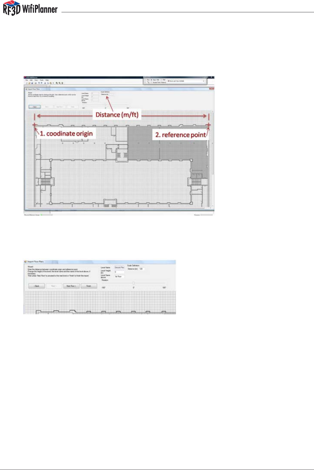
To ensure that all the floor plans for the whole building are aligned one above anoth-
er, you must choose two corresponding reference points in each plan. RF3D WifiPlan-
ner automatically scales and rotates the individual plans to align the selected points
exactly in vertical lines. You only need to take care to select the two points so that
they can be identified exactly on every floor plan. It is a good idea to select the upper
left and right corners of the building as reference points, for example. Furthermore,
you must enter the exact distance between the two reference points. Specify the
distance in the measurement unit selected in the program options, feet or meters.
manual
13
After you have selected the image file for the first floor plan, you can align it with the
grid so that the walls are exactly horizontal and vertical. This will make it much simpler
to draw in the walls later. To align the plan, rotate it using the slider, then use the left
and right arrow keys for finer adjustments.
Then set the “coordinate origin,” such as the upper left corner of the building, and a
second “reference point,” such as the upper right corner of the building. Remember
that the same two points must be identifiable on the plan of every floor. Now enter in-
formation about the plan, including the following items:
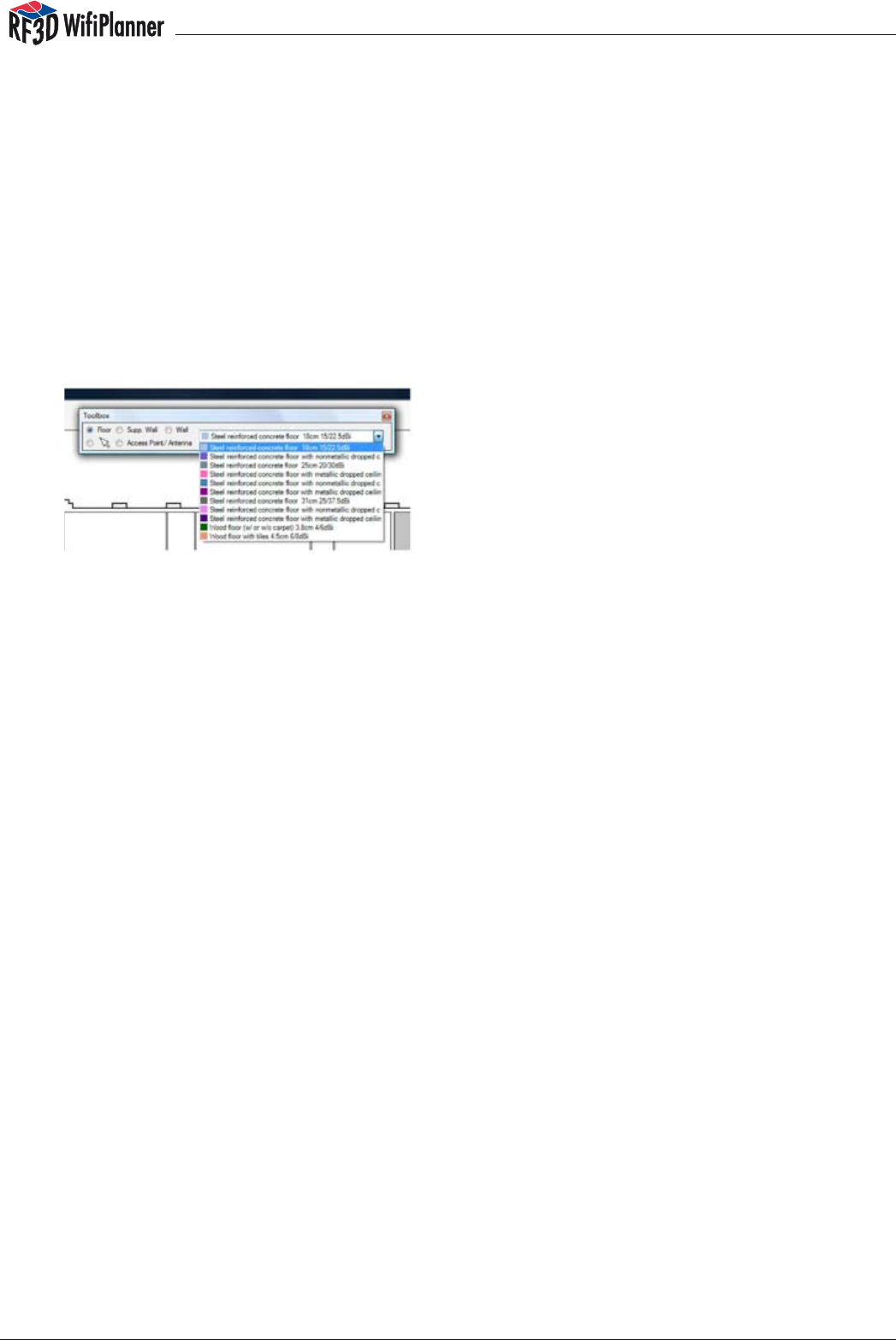
Level Name: Specify a name for the current floor, such as “Ground Level” or “Fifth Floor”.
Level Height: Enter the floor’s elevation above ground level. This value can be negative if
your planning includes underground levels.
Level Name above: Enter the name of the floor above the current floor. When you
later import the next higher floor plan, be sure to give it the name you indicate here.
Mismatched next-level names should only occur in special cases, such as split-level
building plans.
Distance: Specify the distance between the two reference points on this floor. You should
enter this distance as exactly as possible, since coverage calculations may otherwise be
inexact.
Now click Next Floor to import the next plan. This time you do not need to align the image.
Simply click on the same two reference points as in the first plan, in the same order. Repeat
this procedure until you have imported all the floor plans. Click Finish to close the Wizard.
manual
14
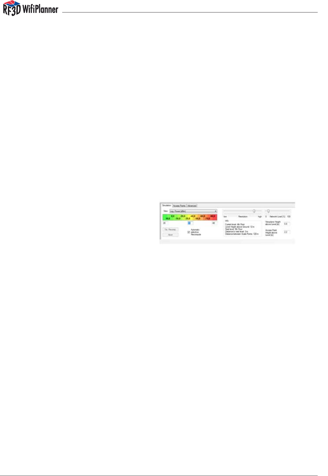
3.2 The Toolbox
The Toolbox provides all the tools you need to design a wireless LAN. When you select Floor,
Supp. Wall, or Wall, the drop-down list to the right in the Toolbox contains a list of the possible
material types for the corresponding building element. To draw in building elements on the
plan, select a material type in the list. The material types are stored in the program as librar-
ies, which can be easily expanded. For details, see Chapter 5, “Advanced Settings”.
As described in Chapter 4, it is a good idea to draw in the plan elements — floors, walls, ac-
cess points, etc. — in a certain order.
Floor1. : Select this tool to describe oors or ceilings. A oor element is a polygon with
any number of sides. If there is an opening in a floor, such as a courtyard surrounded
by the building, you must draw the floor accordingly. For detailed instructions, see
Chapter 5. To draw a floor, click with the left mouse button at the corners of the
desired area. At the last corner, click with the right mouse button to complete the
polygon.
Supp. Wall:2. Supporting walls are elements of the building structure that are continu-
ous through all floors. You should use the supporting wall tool wherever possible in
order to minimize the number of plan elements and make the program’s calculations
significantly faster.
Wall: 3. Use the Wall tool to draw partition walls that are present only in the selected
floor. A wide variety of material types is available for partition walls, and the more ex-
actly you draw all the walls that exist in your building, the better your planning will be.
To draw a wall, click with the left mouse button where the wall begins and at each
angle, then with the right mouse button where the wall ends.
Arrow symbol: 4. Use the arrow tool to select elements in the plan. You can also edit the
plan by dragging and dropping the drawing elements. To select several elements,
press and hold the Ctrl key while you click on them. Clicking on a wall selects only
one segment of it.
Access Point/Antenna:5. Use this tool to place an access point with its antenna in the
plan. To insert an access point without an external antenna, use the antenna type
“Generic Antenna a/b/g 7 dBi Omni.” For all other antennas, select the desired type
from the list. To add new antenna types to the library, see Chapter 5. You can also
download additional antenna libraries from www.rf3d.com.
manual
15
3.3 Drawing and Selecting Elements
First select the desired element in the Toolbox, then choose the appropriate type of
material. Draw in plan elements using both the left and right mouse buttons: rst use the
left mouse button to mark corners, then the right mouse button to finish the element.
Walls, floors and supporting walls are ordinarily drawn only in horizontal and vertical
segments. But you can also draw diagonal segments at any angle simply by pressing
the Ctrl key as you move the mouse. In this way you can draw walls and floors of any
shape desired.
You can also select several walls at once, copy them to the Clipboard, and duplicate
them in a different floor. Press and hold the Ctrl key while you select the desired ele-
ments by clicking on them with the left mouse button. Then select the menu com-
mand Edit/Copy (or press Ctrl+C). Choose the desired oor among the thumbnails
in the left panel, then select the menu command Edit/Paste (or press Ctrl+V). If you
make a mistake in editing the plan, use the menu command Edit/Undo (Ctrl+Z) to
reverse the operation. To restore what you have undone, select Edit/Redo (Ctrl+Y).
3.4 The Simulation Tab
The Simulation tab provides a great
deal of information and several config-
uration options during the simulation of
your projected WLAN.
A. When you first start the RF3D WifiPlanner,
the option “Automatic selective recompute” is activated. This means that the wireless
network characteristics are recalculated automatically whenever you draw or move
elements in the plan. This makes interactive planning easy. However, you may want to
turn off automatic recomputing until you have completed at least a rough draft of your
network plan. When the automatic recompute option is deactivated, you can click the
“Tot.Recomp.” button at any time to recompute the wireless network characteristics.
B. The box labeled Info contains the basic information about the current floor.
C. The “Resolution” control allows you to choose how precisely you want the WLAN charac-
teristics to be computed. Low resolution uses yields a rough estimation of the wireless net-
work characteristics, while high resolution results in very precise calculations. Note that
the resolution setting has drastic effects on the computation time and the program’s
memory needs, however. Low resolution is therefore recommended for interactive plan-
ning work. Once you have completed your plan, you can use higher resolution to gener-
ate reports.
D. The Network Load control allows you to simulate various data traffic levels in your pro-
jected wireless network. This is very helpful since it allows you to design your network ac-
cording to the types of applications it will support. Low network loads can be expected
for example in warehousing and logistics applications, while office applications and
Voice-over-IP usually generate higher traffic loads.
E. View: In this drop-down list you can choose the network characteristic that you want to
display. The list contains the following views:

manual
16
Log. Power
This is the received signal strength of the strongest access point at each location. Use
this view to gauge the quality of your network coverage. A value of –70 dB or higher
is sufcient. (Remember that, since the values in dB are negative, a higher value is one
that is closer to zero.)
Log. SNR
This view shows the signal-to-noise ratio at each location, which reflects the effects of
co-channel interference. A value of 10 dB or higher is good.
Data Rate
The data rate view shows the estimated attainable data rate at each location. This is
a very useful prediction of how the projected network will actually perform. The display
shows values between 1 and 54 Mbit/s. Higher data rates are better.
Interference
Interference is a major concern in wireless network planning. Interference is caused
mainly by co-channel overlap with other access points. Reduce interference by select-
ing different channels for adjacent access points, or by reducing the output power of
certain access points. This will reduce the size of the cell. How much interference you
want to accept depends on your specific needs for redundancy and for throughput.
Redundancy (full version only)
Access point redundancy is important in areas that require continuous network avail-
ability even when local failures or system overloads occur. The RF3D WifiPlanner provides
various views to help you plan access point redundancy. Each view simulates a certain
scenario in which you can ensure that critical areas have adequate backup cover-
age.
Log. Power Reliability Level 1
This view displays the signal strength received from the second strongest access point at
each location, assuming that the strongest access point is no longer working.
Log. Power Reliability Level 2
This view displays the signal strength received from the third strongest access point at
each location, assuming that the strongest access point is no longer working.
Log. SNR Reliability Level 1
This view displays the signal-to-noise ratio at each location assuming that the strongest
access point is no longer working.
Log. SNR Reliability Level 2
This view displays the signal-to-noise ratio at each location assuming that the two strong-
est access points are no longer working.
F. The color scale indicates what numeric values correspond to the colors in the main dis-
play. You can modify the range and the number of gradations in the input fields below
the color scale. This is practical when you would like to display finer distinctions in the
plan.
manual
17
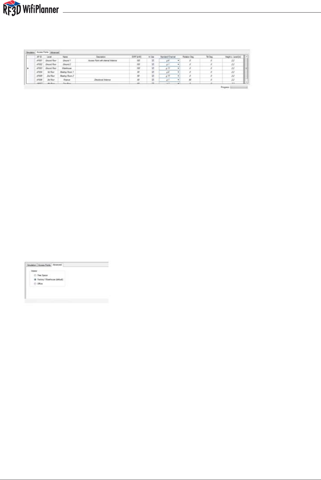
3.5 The Access Point Tab
The Access Points tab lists all the access points currently planned, and allows you to
modify their properties. The properties of each access point include a name and a
description, the transmitter power, the channel setting, and the antenna orientation.
The orientation is expressed in terms of rotation in the horizontal plane and inclina-
tion from the vertical. The rotation is entered in degrees, as on a compass, measured
clockwise from the top of the plan: 0° indicates that the antenna is aimed “north”,
or towards the top of the plan; 90° is to the right, 180° towards the bottom, etc. In the
Tilt field, a positive value indicates that the antenna is tilted upwards, and a negative
value indicates the inclination downwards. 0° means that the antenna is in its normal
orientation with respect to the horizontal plane.
3.6 Advanced Settings
In addition to walls and floors, enclosed spaces also contain many movable obstacles,
such as people in offices and merchandise in warehouses, and objects that would
be too difficult to draw in individually, such as furniture, shelves etc. For this reason, the
Advanced tab allows you to set a global average attenuation factor to account for
such objects in different kinds of spaces.
Select Free Space if there is no additional loss to be anticipated, as in outdoor areas
such as parking lots or campus yards.
The default setting, Factory/Warehouse, factors in low to moderate loss for low-density
spaces such as warehouses.
The Office setting adds moderate to high attenuation to account for the furniture
and persons present in typical office environments.
4 Planning Wireless Networks
4.1 What Application Is Intended?
To plan a wireless network, start by determining which applications will eventually be
transported over the projected network. There are critical differences between applica-
tions that require greater redundancy, but only low data traffic, such as warehousing
and logistics, and applications that require high bandwidth, such as voice-over-WLAN.
manual
18
For a warehouse application, for example, you should design the wireless cells larger and
tolerate a higher level of interference. This increases reliability, since the second nearest
access point to a given location will probably be usable in case the nearest one fails. To
change the size of the wireless cells, click the Access Points tab and adjust the transmit-
ter power of each access point. The higher the transmitter power of an access point, the
larger the cell it covers.
Inversely, if you are designing a network for voice-over-WLAN, you should plan smaller
cells. This is because interference should be minimized for voice-over-WLAN, since voice
packets that are lost due to interference are not resent, as lost packets in other applica-
tions are. Thus interference affects voice fidelity, and in extreme cases can make voice
communication impossible.
4.2 Entering Environmental Factors
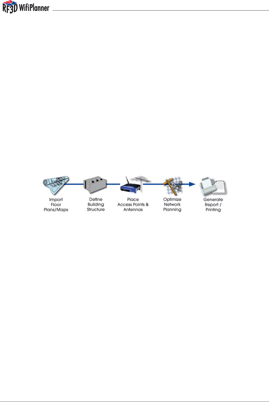
In planning a wireless network with the RF3D WifiPlanner, you should follow a certain se-
quence of steps in order to achieve your objective quickly and easily. Furthermore, perform-
ing the steps in the order described here minimizes the computation involved, and hence
the processing time as well. The process can be divided into ve simple steps:
Once you have imported all the building plans as described in Section 3.1, you should first
draw in the floors in each level. If all the floors in the building are of the same shape and the
same materials, you can copy the first floor to all the other plans using the menu command
Edit/Paste Floor to Other Levels.
Hint: Before you begin drawing in all the building elements, you can turn off the Automatic
selective recompute function as described in Section 3.4. This will save processor time, since
otherwise the RF3D WifiPlanner recomputes the wireless network characteristics each time
you draw an element of the building plan.
There are two different kinds of walls in the RF3D WiPlanner: supporting walls, drawn with the
Supp. Wall tool in the Toolbox, and partition walls, drawn with the Wall tool. When you draw a
supporting wall, it is automatically inserted in all levels of the building, and the RF3D WifiPlan-
ner treats it as a single element. You should use supporting walls to represent all the walls in
your building that have the same position and material composition in all levels. This can sig-
nificantly reduce the processing time in comparison to normal walls drawn in on each level
separately, since there are fewer elements to be processed by the computing algorithms.
After you have drawn in all the supporting walls, you should draw in the partition walls on
each level.
manual
19
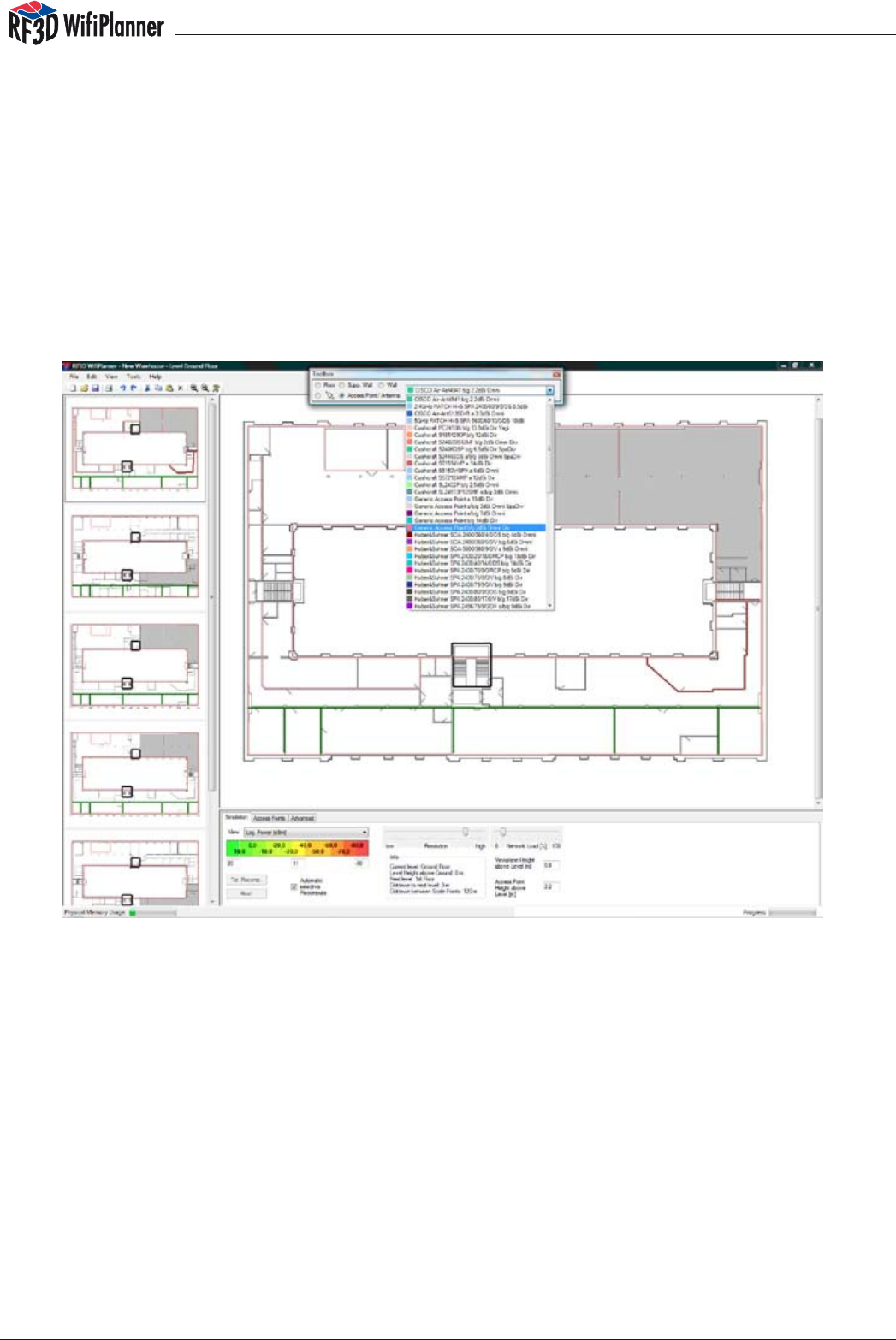
4.3 Positioning Access Points
Now that you have drawn all the elements of the building, you can begin to design
the WLAN itself by positioning the access points and defining their properties. Be-
cause RF3D WifiPlanner considers each access point in combination with its antenna,
you should know what type of antenna you are thinking of using when you select the
Access Point tool in the Toolbox. If you plan to use an access point without an external
antenna, you can select one of the “Generic” types. RF3D WifiPlanner has a library
containing a number of external antenna definitions. When you use a directional an-
tenna, you can aim it in your plan as described in Section 3.5.
Select the desired antenna in the Toolbox list.
When you begin to position your access points, you should make sure that sufficient
signal power can be received everywhere in the building. Sufficient signal power gen-
erally means a value of –60 dBm or better. Another thing to consider in your planning
is interference. Primarily, this means avoiding co-channel interference, which occurs
when adjacent access points use overlapping channel settings.
manual
20
Sufficient signal power (–60 dBm or better) throughout the building..
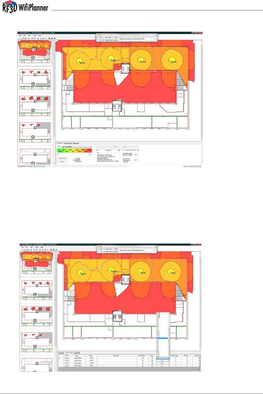
Start your planning with the access points in the lowest level, and use a cellular struc-
ture as described in Section 2.3. Set the communication channels of the access points
in conformance with national restrictions. When you continue with the access points
in the other levels, remember that access points transmit through floors and ceilings.
Your cellular structure should therefore take into account the access points located
above and below one another.
Setting the communication channels for all access points. Avoid channel overlap.
manual
21
When you choose channels for the access points, it can be helpful to switch the view
mode from signal power to data rate, because the data rate view reflects any adverse
effects of co-channel or near-channel interference due to channel settings.
Checking the results of access point settings in the Data Rate view.
4.4 Optimizing Wireless Networks
When you have finished planning wireless signal coverage for the building, you can
begin to optimize the network. You can do this in several ways, using the RF3D WifiPlan-
ner’s various views on the Simulation tab, such as data rate, interference, etc. One
approach is to display the expected data rates. The data rate view reflects all radio
effects, including interference, signal-to-noise ratio and network traffic loads. Gaps or
areas with lower data rates indicate room for improvement. To analyze the causes of
lower data rates, you can use the interference or SNR views. The problems can be al-
leviated by changing the access point settings.
When you are satisfied with your basic WLAN plan, you can then simulate its behavior
in case of faults, such as access point failures. Do this by deactivating individual ac-
cess points on the Access Points tab. A better way, however, is to use the “Log. Power
Reliability Level 1” view. In this view, RF3D WifiPlanner displays the signal power that
would be received at each location in the plan if the strongest access point for that
location had failed. For high-reliability applications, gaps in the coverage in this view
can be a problem. You can fill such gaps by adding access points.
There is always more than one way to design a wireless network. The need for a reliable or
“high-availability” network is often difficult to reconcile with the need to ensure high data
rates by avoiding interference. You will find, however, that networks you have designed using
RF3D WifiPlanner are efficient, optimum solutions.

manual
22
5 Advanced Settings
5.1 Editing Wall and Floor Libraries
he properties and settings of wall and floor materials are stored in the library. You can
easily edit and expand this library. Each type of wall or oor is saved in a separate XML
file. These files are contained in the folder RF3DWifiPlanner/WallsFloors.
The names of the wall and floor files must follow certain rules in order to be recognized
by the RF3D WiPlanner program. Example: ft_003_6-_Brick_7_18dB. The le name must
begin with ‘ft’ or ‘m’ to indicate whether this wall or floor is defined in feet or in meters.
The wall or floor is then available in the Toolbox only when the same measurement
unit is selected in the program options. The next part of the file name after the meas-
urement unit abbreviation is an underscore followed by a three-digit number. This
number determines the position at which the given wall or floor type appears in the
toolbox list. After another underscore comes the name you want to use for this wall or
floor type.
The best way to create a wall or floor type is to find a file that defines a similar, existing
type, open it in Notepad, and save it under a new name before editing its contents.
The lines you can edit are explained with examples below.
The Type line defines the name displayed in the Toolbox.
<Type id=“ref-4“>6“ Brick 7/18dB</Type>
The DampA_dB line indicates the signal attenuation through such a wall or oor in dB
in the 5 GHz band used for 802.11 a and h networks.
<DampA_dB>7</DampA_dB>
The DampBG_dB line indicates the signal attenuation through such a wall or oor in
dB in the 2.4 GHz band used for 802.11 b and g networks.
<DampBG_dB>18</DampBG_dB>
The GaugeFeet line indicates the thickness of the wall or floor in feet. If you enter a
non-zero value here, you should enter zero in the GaugeMeter line below.
<GaugeFeet>0.5</GaugeFeet>
The GaugeMeter line indicates the thickness of the wall or oor in meters. If you enter
a non-zero value here, you should enter zero in the GaugeFeet line above.
<GaugeMeter>0</GaugeMeter>
The knownColor line defines the color in which you will draw the wall or floor in the level
plans. For permissible color names, see the table in Appendix c.
<knownColor>142</knownColor>
The IsFloor line determines whether the building element described in this file is a wall
or a floor. If IsFloor is true, it’s a floor. If IsFloor is false, the file describes a wall.
<IsFloor>false</IsFloor>
If you have edited a copy of an existing library file, you must leave all other parts of
the file unchanged. Otherwise, the program may behave unexpectedly.

manual
23
5.2 Editing the Access Point/Antenna Library
The antenna library, like the wall and floor library, is stored in the form of individual files
for each antenna type. These files are contained in the folder RF3DWifiPlanner/Anten-
nas, and can be edited with Notepad. The best way to create an antenna type is to
find the file that defines a similar, existing type, open it in Notepad, and save it under
a new name before editing its contents.
Any antenna can be defined for the 2.4 GHz band, the 5 GHz band, or both bands.
The example used in the following explanation defines an antenna for the 2.4 GHz
band only.
An antenna file describes the antenna’s radiation pattern in terms of its horizontal
and vertical cross-sections, as well as some additional parameters. The antenna’s ra-
diation pattern must be described for the antenna’s normal installation orientation.
Theta (θ) represents the upward elevation angle from the horizontal plane in degrees.
Negative values indicate downward elevation. Phi (ϕ) designates the azimuth angle
in degrees — that is, the rotational angle in the horizontal plane, where positive val-
ues represent a clockwise rotation from 12 o’clock. Directional antennas should be
described so that their greatest gain is at phi=0° and theta=0°.
You can enter as many directional gain values (data points) as you want, and the
number of data points only has to be entered in a few places, as described below.
The data points you specify can also be at any angles desired, and their distribution
can vary within an antenna file. However, both the precision of the program display
and the time required to recompute and refresh the display increase as the number
of data points increases.
In computing the antenna gain, the program adds the directional gain in dBi to the
global gain (in the example, 4 dBi). This means that the directional gain value should
be normalized to 0 dBi.
Please note that the decimal point must be a period (‘.’). Note too that the tags and
values are case-sensitive.
The Type line contains the text displayed for this antenna type in the toolbox.
<Type id=“ref-4“>SOA 2400/360/4/0/DS</Type>
The TypeShort line is not currently used in the program.
You can use it for your comments.
<TypeShort id=“ref-5“>Bild 6, 139.26.0044</TypeShort>
The Gain_dB_2_4GHz line denes the antenna gain in the 2.4 GHz band.
<Gain_dB_2_4GHz>4</Gain_dB_2_4GHz>

manual
24
The IsZIsotropic_2_4GHz line indicates whether the antenna is approximately omnidirec-
tional in the horizontal plane in the 2.4 GHz band. The value true indicates that its radia-
tion pattern is roughly rotationally symmetric with respect to the vertical axis.
<IsZIsotropic_2_4GHz>true</IsZIsotropic_2_4GHz>
The Gain_dB_5GHz line denes the antenna gain in the 5 GHz band.
<Gain_dB_5GHz>0</Gain_dB_5GHz>
The IsZIsotropic_5GHz line indicates whether the antenna is approximately omnidirec-
tional in the horizontal plane in the 5 GHz band. The value true indicates that its radia-
tion pattern is roughly rotationally symmetric with respect to the vertical axis.
<IsZIsotropic_5GHz>false</IsZIsotropic_5GHz>
The Is2_4GHz line species whether the antenna can be used in the 2.4 GHz band.
<Is2_4GHz>true</Is2_4GHz>
The Is5GHz line specifies whether the antenna can be used in the 5 GHz band.
<Is5GHz>false</Is5GHz>
The next few lines are references to data defined later in the file.
Do not change these lines!
<Phi_Deg_2_4GHz href=“#ref-6“/>
<Theta_Deg_2_4GHz href=“#ref-7“/>
<Phi_dBi_2_4GHz href=“#ref-8“/>
<Theta_dBi_2_4GHz href=“#ref-9“/>
<Phi_Deg_5GHz href=“#ref-10“/>
<Theta_Deg_5GHz href=“#ref-11“/>
<Phi_dBi_5GHz href=“#ref-12“/>
<Theta_dBi_5GHz href=“#ref-13“/>
<Col>
<name xsi:null=“1“/>
<value>0</value>
The knownColor line specifies the color in which the given antenna is displayed in
the level plans. For the permissible color values, see Appendix C.
<knownColor>59</knownColor>
<state>1</state>
</Col>
</a1:AntennaType>

manual
25
The array, or list of values, which follows contains phi values (angle measures in de-
grees) for 72 data points at 2.4 GHz. If you use a different number of data points,
replace the “72” in this line with the number of data points you want to define.
<SOAP-ENC:Array id=“ref-6“ SOAP-ENC:arrayType=“xsd:float[72]“>
<item>-180</item>
<item>-175</item>
<item>-170</item>
.
.
.
<item>165</item>
<item>170</item>
<item>175</item>
</SOAP-ENC:Array>
The next array, with the attribute id=”ref-7”, contains theta values (angle measures in
degrees) for 72 data points at 2.4 GHz.
<SOAP-ENC:Array id=“ref-7“ SOAP-ENC:arrayType=“xsd:float[72]“>
<item>-90</item>
<item>-85</item>
<item>-80</item>
.
.
.
<item>255</item>
<item>260</item>
<item>265</item>
</SOAP-ENC:Array>
The next array, with the attribute id=”ref-8”, contains gain values in dBi for the values
of phi listed above, representing 72 data points at 2.4 GHz.
<SOAP-ENC:Array id=“ref-8“ SOAP-ENC:arrayType=“xsd:float[72]“>
<item>-2.381</item>
<item>-2.399</item>
<item>-2.388</item>
.
.
.
<item>-2.005</item>
<item>-2.175</item>
<item>-2.303</item>
</SOAP-ENC:Array>

manual
26
The next array, with the attribute id=”ref-9”, contains gain values in dBi for the values
of theta listed above, representing 72 data points at 2.4 GHz.
<SOAP-ENC:Array id=“ref-9“ SOAP-ENC:arrayType=“xsd:float[72]“>
<item>-16.683</item>
<item>-12.24</item>
<item>-7.157</item>
.
.
.
<item>-5.032</item>
<item>-7.721</item>
<item>-12.307</item>
</SOAP-ENC:Array>
The next array, with the attribute id=”ref-10”, contains a phi value (angle measure in
degrees) for one data point at 5 GHz. This array is rudimentary, since the antenna is
not used for the 5 GHz band.
<SOAP-ENC:Array id=“ref-10“ SOAP-ENC:arrayType=“xsd:float[1]“>
<item>0</item>
</SOAP-ENC:Array>
The next array, with the attribute id=”ref-11”, contains a theta value (angle measure
in degrees) for one data point at 5 GHz.
<SOAP-ENC:Array id=“ref-11“ SOAP-ENC:arrayType=“xsd:float[1]“>
<item>0</item>
</SOAP-ENC:Array>
The next array, with the attribute id=”ref-12”, contains a gain value in dBi for the value
of phi listed above, representing one data point at 5 GHz.
<SOAP-ENC:Array id=“ref-12“ SOAP-ENC:arrayType=“xsd:float[1]“>
<item>0</item>
</SOAP-ENC:Array>
The next array, with the attribute id=”ref-13”, contains a gain value in dBi for the value
of theta listed above, representing one data point at 5 GHz.
<SOAP-ENC:Array id=“ref-13“ SOAP-ENC:arrayType=“xsd:float[1]“>
<item>0</item>
</SOAP-ENC:Array>
All other lines in the file must remain unchanged.
manual
27
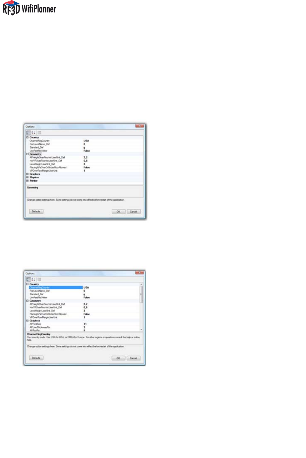
5.3 Options and Settings
To adjust other program settings, select the the menu command Tools/Options. The
Country option group allows you to set appropriate parameters for the country where
you are located. The Geometry option group lets you specify default values for the
height of new access points above the floor, the vertical distance between floors, etc.
The options in the Graphics group allow you to set display properties, and the Physics
option group allows you to set basic physical parameters for radio signal calcula-
tions. Finally, the options in the Printer group allow you to control how your planning
diagrams are printed.
To change any setting, click on the existing value. A description of the parameter ap-
pears in the box below the options list. After you have changed one or more of these
settings, you must exit the program and restart it for your new settings to take effect. To
reset all options to their original values, click the “Defaults” button.
5.4 Floors with Openings
Some buildings have open areas in the floors, such as inner courtyards. Such areas
must be left open in your plans as well in order for interference to be computed cor-
rectly. You can draw oors with open areas as follows: First, draw some of the edges
of the floor along the outer walls, but do not complete the polygon. Then draw the
edges of the open space in the interior.
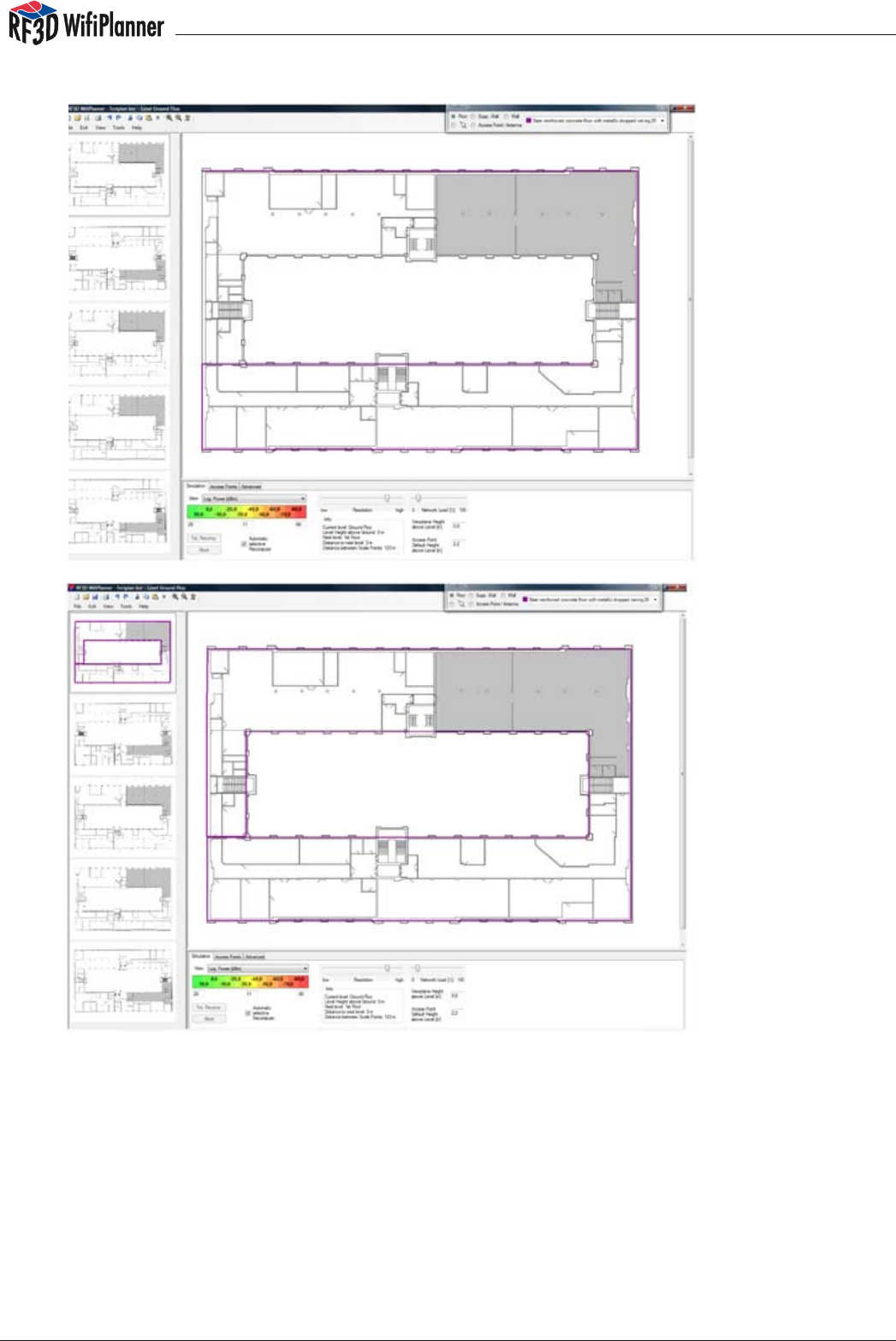
manual
28
In this way you can draw the floor in one piece while leaving an interior area open.
5.5 Split-Level Buildings
To represent buildings with split levels, import a drawing for each partial level and
draw in partial floors for the existing floor areas. Remember, though, that walls you
draw in on a lower level extend only to the height of the next higher level, even if they
do not meet a floor there. If your building has walls that extend through a split level,
you must draw them on the lower level and again in the unfloored space on the next
higher, partially floored level.
manual
29
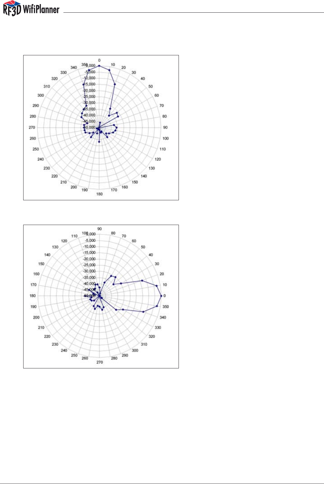
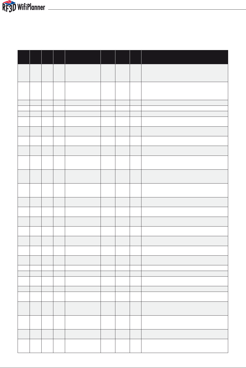
Appendix A The Antenna Library
Antenna Library
Hier finden Sie die Antennendiagramme für die in RF3D WifiPlanner hinterlegten
generischen Antennentypen.
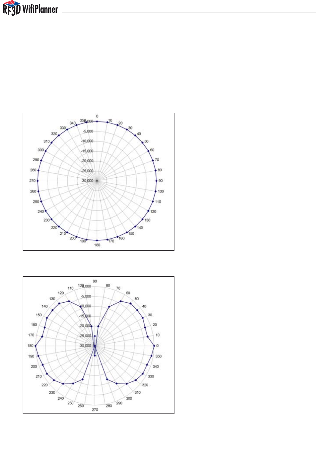
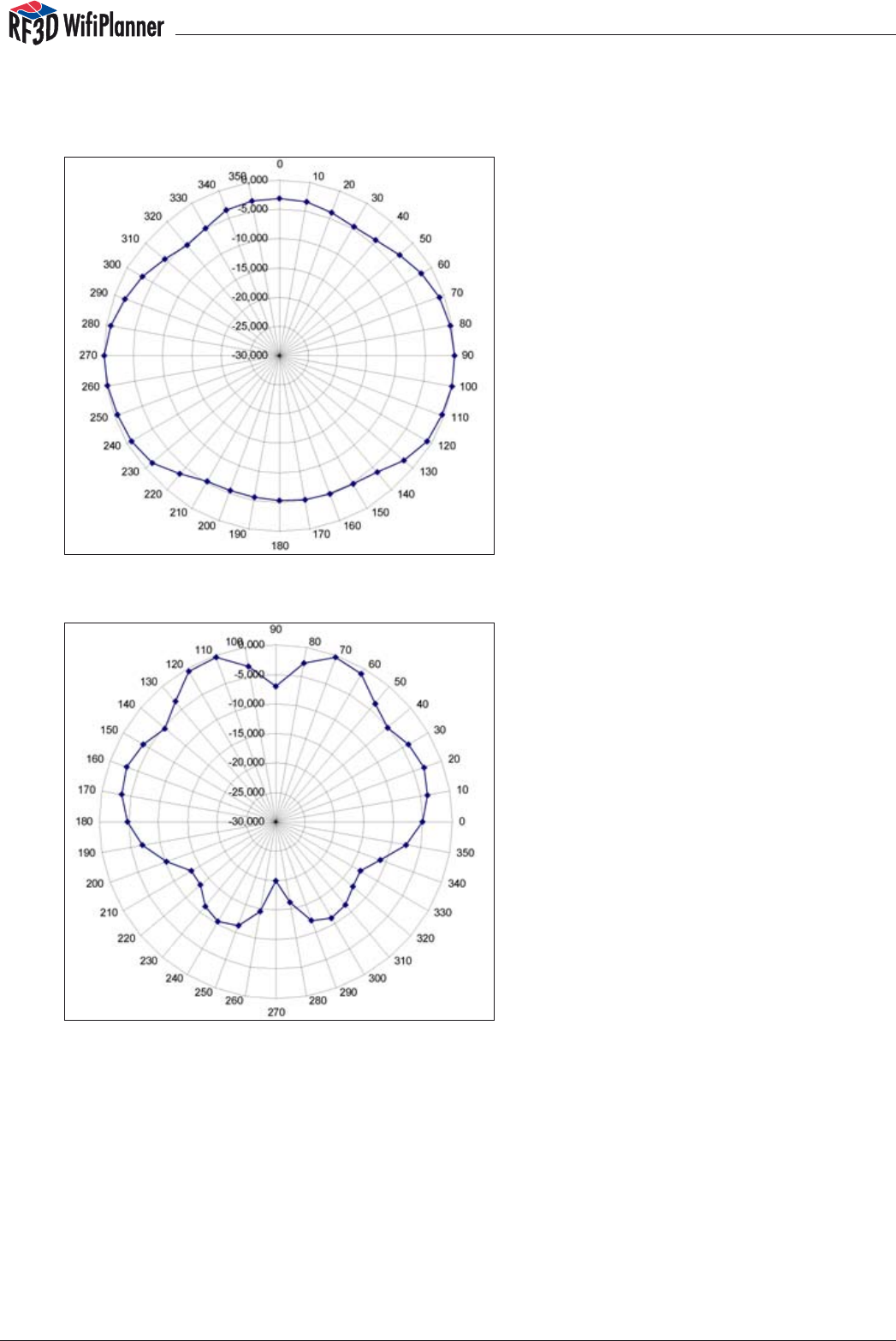
Generic Access Point w/ Dipole Ant a/b/g 2dBi
Horizontal section of a/b/g Net
Vertical section of a/b/g Net
manual
30
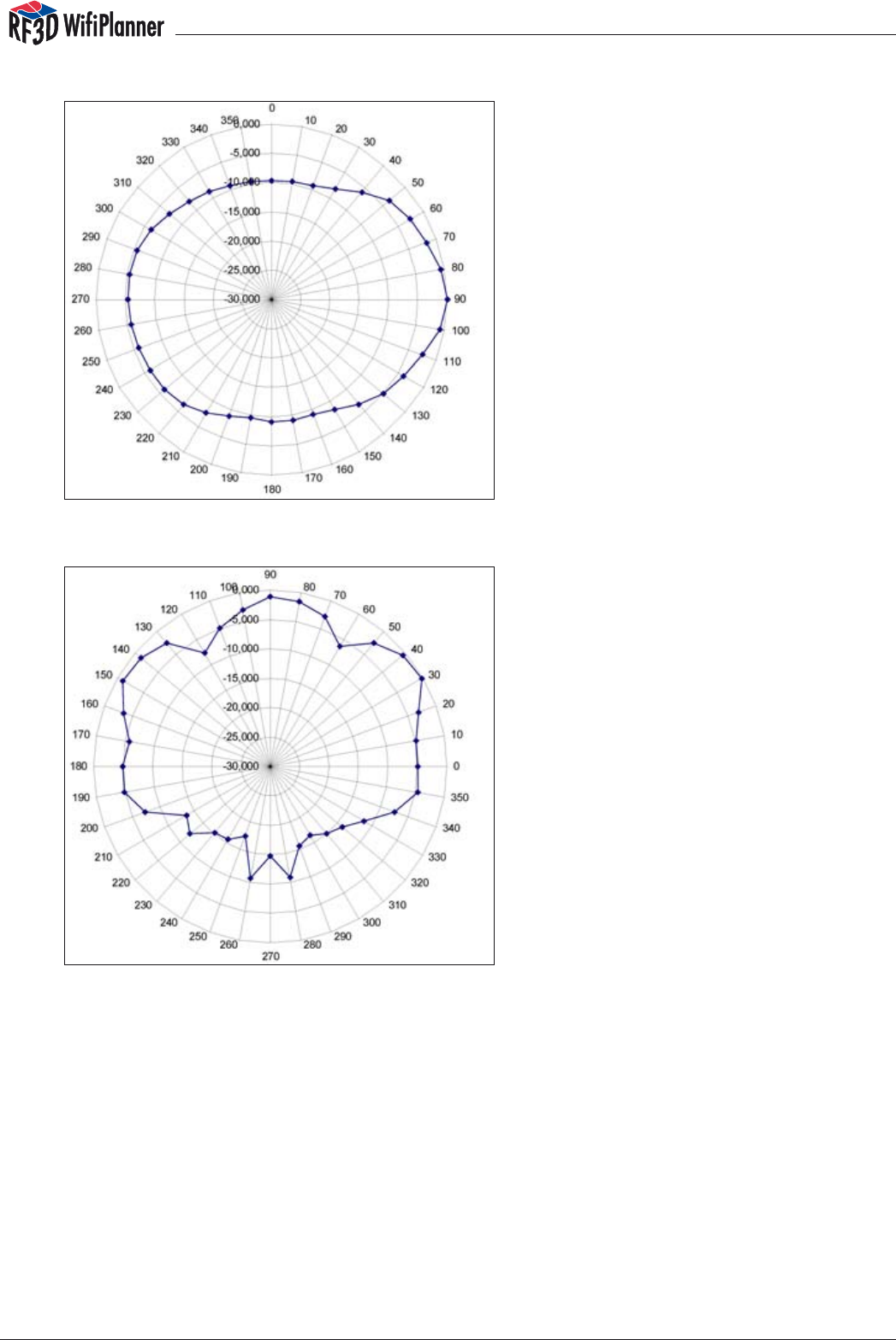
Generic Antenna a/b/g 7dBi Omni
Horizontal section of b/g Net
Vertical section of b/g Net
manual
31
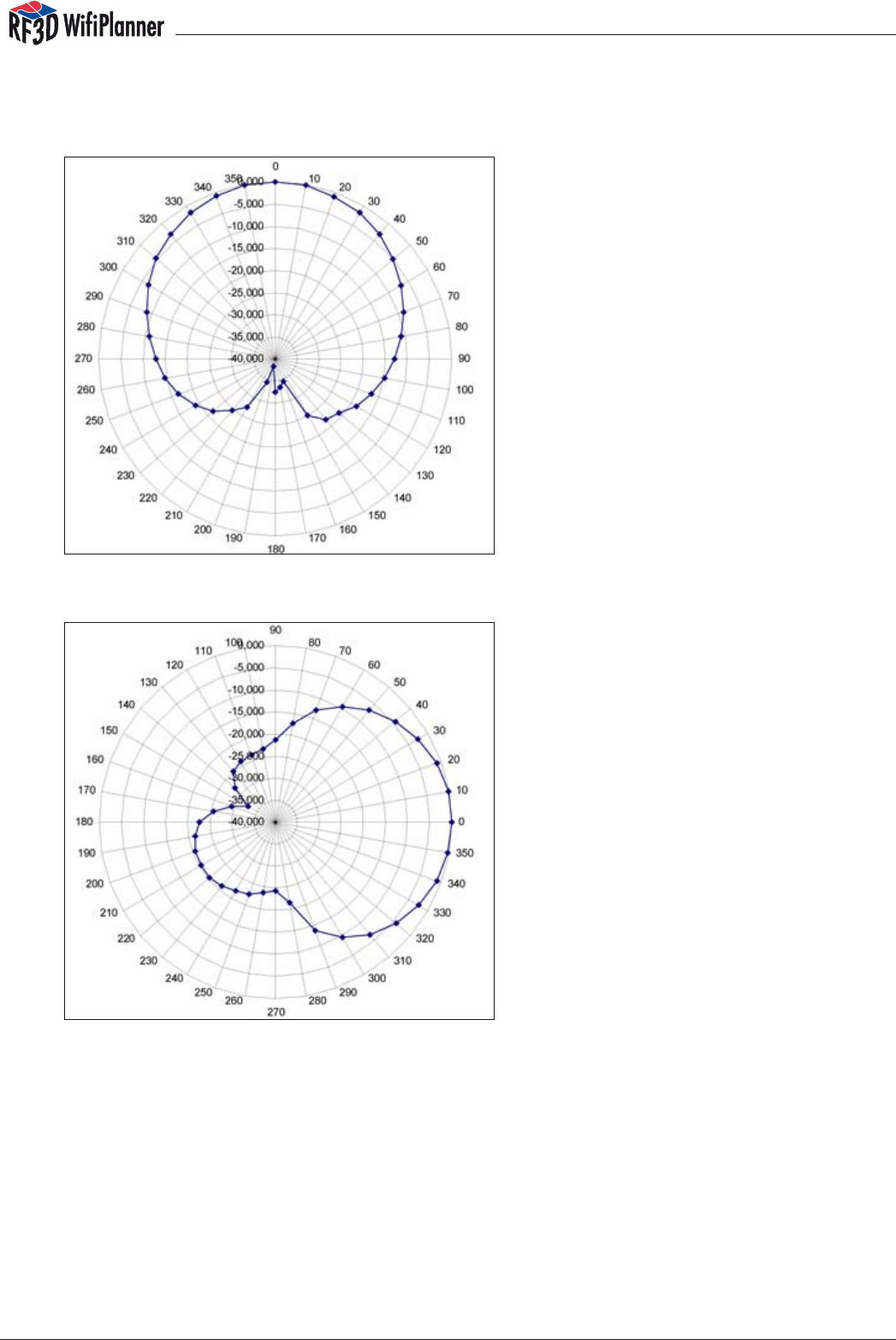
Horizontal section of a/h Net
Vertical section of a/h Net
manual
32
Generic Antenna a/b/g 8dBi directional
Horizontal section of a/b/g Net
Vertical section of a/b/g Net
manual
33
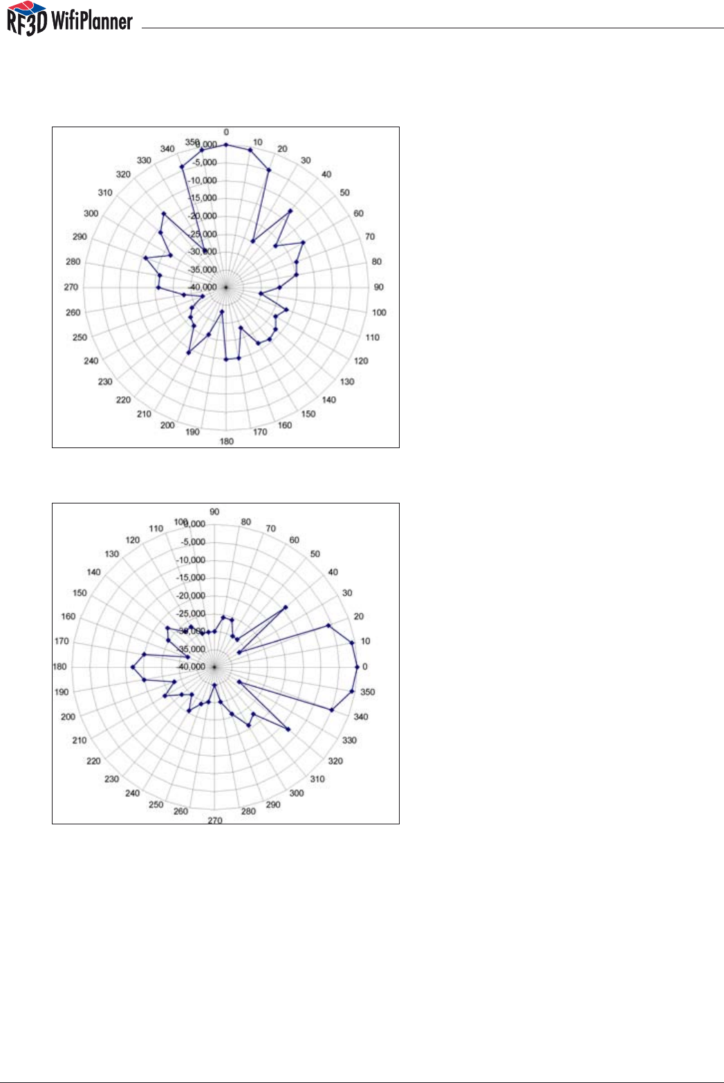
Generic Antenna a/b/g 13,9 dBi Directional Yagi
Horizontal section of a/b/g Net
Vertical section of a/b/g Net
manual
34
Generic Antenna a/b/g 18 dBi Directional
Horizontal section of a/b/g Net
Vertical section of a/b/g Net
manual
35
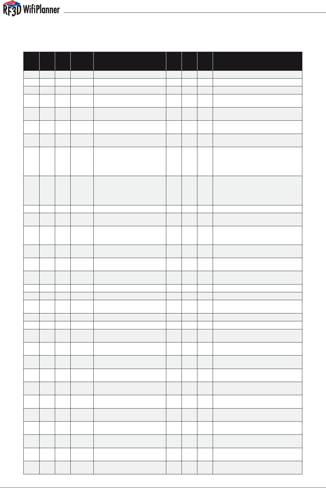
Appendix B The Wall and Floor Library
List of wall & floor materials measurement unit: feet
Floor /
Wall
Att. 2.4
GHz
[dB]
Att. 5
GHz
[dB]
Thick-
ness
[in]
RF3D
Toolbox Text Nr RF3D Nr RF3D
Lite
Color-
Code Discribtion
Wall 16,0 24,0 8 8“ Concrete Block w/
Steel 16/24dB
1 1 144 Concrete block, when reinforced with concrete columns
and tie beams, is a very common building material for
the load-bearing walls of buildings, in what is termed CBS
construction for Concrete Block Structure.
Wall 22,0 33,0 12 12“ Concrete Block w/
Steel 22/33dB
2 2 146 Concrete block, when reinforced with concrete columns
and tie beams, is a very common building material for
the load-bearing walls of buildings, in what is termed CBS
construction for Concrete Block Structure.
Wall 7,0 18,0 6 6“ Brick 7/18dB 3 3 142 Brick wall
Wall 10,0 25,0 10 10“ Brick 10/25dB 4 83 Brick wall
Wall 13,0 32,5 20 20“ Brick 13/32.5dB 5 39 Brick wall
Wall 17,0 25,5 8 8“ Concrete w/Steel
17/25dB
6 6 102 Steel reinforced concrete wall
Wall 24,0 36,0 12 12“ Concrete w/Steel
24/36dB
7 7 101 Steel reinforced concrete wall
Wall 33,0 49,5 16 16“ Concrete w/Steel
33/50dB
8 8 68 Steel reinforced concrete wall
Wall 2,0 3,0 8 8“ Light-Weight Con-
crete w/Steel 2/3dB
9 61 Light-weight concrete wall
Wall 0,8 0,8 N/A 5“ Drywall (2 sides)
Over Framing .8/0.8dB
10 10 97 Drywall, also commonly known as gypsum board, plaster-
board. A drywall panel is made of a paper liner wrapped
around an inner core made primarily from gypsum plaster.
Wall 0,8 0,8 N/A 7“ Drywall (2 sides)
Over Framing .8/0.8dB
11 11 92 Drywall, also commonly known as gypsum board, plaster-
board. A drywall panel is made of a paper liner wrapped
around an inner core made primarily from gypsum plaster.
Wall 1,5 1,5 N/A 4“ Plywood (1
side) Over Framing
1.5/1.5dB
12 80 One layer Plywood wall
Wall 3,0 3,0 N/A 4.5“ Plywood (2 sides)
Over Framing 3/3dB
13 53 Two layer Plywood wall
Wall 15,0 15,0 1 1“ Stucco Over 2x4
Wood or Steel 15/15dB
14 14 95 Modern Stucco usually consists of 1 layer of wire lath and
2 layers of portland cement-based plaster
Wall 3,0 4,5 1 Window-1“ Dual
Glazed 3/4.5dB
15 91 Glass window
Wall 28,0 42,0 1 Window-1“ IR-blocking
28/42dB
16 69 Infrared blocking window
Wall 2,0 3,0 2“-4“ Office divider
glass/wood 2/3dB
17 127 Office divider
Wall 1,0 1,5 2 2“ Office cubical
1/1.5dB
18 128 Office divider
Wall 1,5 2,3 36 Shelf/Rack 3‘
1.5/2.25dB
19 56 Shelf/rack
Wall 3,0 4,5 72 Shelf/Rack 6‘ 3/4.5dB 20 125 Shelf/rack
Wall 4,0 6,0 96 Shelf/Rack 8‘ 4/6dB 21 126 Shelf/rack
Wall 30,0 45,0 Wall or Ceiling-Corru-
gated Steel 30/45dB
22 62 Metal wall sheeting in the form of Corrugated galvanized
iron
Wall 30,0 45,0 Elevator shaft 30/45dB 23 23 35 Elevator shaft
Floor 17,0 25,5 8 8“ Concrete w/Steel
17/25.5dB
100 100 102 Steel reinforced concrete floors
Floor 18,0 27,0 8 8“ Concrete/Steel w/
Nonmetallic Drop Ceil-
ing 18/27dB
101 101 152 Steel reinforced concrete floors with nonmetallic dropped
ceiling
Floor 27,0 40,0 8 8“ Concrete/Steel w/
Metallic Drop Ceiling
27/40dB
102 82 Steel reinforced concrete floors with metallic dropped
ceiling
Floor 20,0 30,0 10 10“ Concrete w/Steel
20/30dB
103 103 101 Steel reinforced concrete floors
Floor 21,0 31,5 10 10“ Concrete/Steel w/
Nonmetallic Drop Ceil-
ing 21/31dB
104 104 156 Steel reinforced concrete floors with nonmetallic dropped
ceiling

manual
36
Floor 30,0 45,0 10 10“ Concrete/Steel w/
Metallic Drop Ceiling
30/45dB
105 55 Steel reinforced concrete floors with metallic dropped
ceiling
Floor 24,0 36,0 12 12“ Concrete w/Steel
24/36dB
106 106 68 Steel reinforced concrete floors
Floor 25,0 37,5 12 12“ Concrete/Steel w/
Nonmetallic Drop Ceil-
ing 25/37dB
107 107 162 Steel reinforced concrete floors with nonmetallic dropped
ceiling
Floor 34,0 51,0 12 12“ Concrete/Steel w/
Metallic Drop Ceiling
34/51dB
108 84 Steel reinforced concrete floors with metallic dropped
ceiling
Floor 4,0 6,0 1,5 1.5“ Wood Flooring w/
Subfloor 4/6dB
120 53 Wood Flooring with subfloor
Floor 6,0 8,0 1,5 1.5“ Tile w/ Subfloor
6/8dB
121 60 Tile with subfloors
manual
37
List of wall & floor materials measurement unit: meter
Floor /
Wall Att. 2.4
GHz
[dB]
Att. 5
GHz
[dB]
(Mean)
Thickness
cm
RF3D Text Nr Lite Nr Color-
Code Comment
Wall 8 20 18 Brick wall 18cm 8/20dB 1 1 142 Brick wall
Wall 10 25 25 Brick wall 25cm 10/25dB 2 2 83 Brick wall
Wall 13 32,5 50 Brick wall 50cm 13/32.5dB 3 3 39 Brick wall
Wall 15 22,5 18 Steel reinforced concrete wall
18cm 15/22.5dB 4 4 102 Steel reinforced concrete wall
Wall 20 30 25 Steel reinforced concrete wall
25cm 20/30dB 5 5 101 Steel reinforced concrete wall
Wall 25 37,5 31 Steel reinforced concrete wall
31cm 25/37.5dB 6 6 68 Steel reinforced concrete wall
Wall 2 3 18 Light-Weight concrete/gas con-
crete 18cm 2/3dB 7 61 Light-weight concrete wall
Wall 0,8 0,8 N/A Dry wall/1.5cm plasterboard
each side 0.8/0.8dB 8 8 97 Drywall, also commonly known as gyp-
sum board, plasterboard. A drywall
panel is made of a paper liner wrapped
around an inner core made primarily
from gypsum plaster.
Wall 1,6 1,6 N/A Dry wall/3.0 cm plasterboard at
each side 1.6/1.6dB 9 9 92 Drywall, also commonly known as gyp-
sum board, plasterboard. A drywall
panel is made of a paper liner wrapped
around an inner core made primarily
from gypsum plaster.
Wall 4 6 3,8 Wood Wall 3.8cm 4/6dB 10 80 One layer wood wall
Wall 8 12 N/A Wood Wall/3.8cm each side
8/12dB 11 53 Two layer wood wall
Wall 15 15 2,6 Stucco wall 2.6cm 15/15dB 12 95 Modern Stucco usually consists of 1 layer
of wire lath and 2 layers of portland ce-
ment-based plaster
Wall 3 4,5 3 Double Glazed Window 3cm
3/4.5dB 14 91 Glass window
Wall 28 42 3 IR-blocking Window 3cm
28/42dB 15 69 Infrared blocking window
Wall 2 3 N/A Office divider glass/wood
5-10cm 2/3dB 16 127 Office divider
Wall 1 1,5 5 Office cubical 5cm 1/1.5dB 17 128 Office divider
Wall 1,6 2,4 100 High rise rack 100cm 1.6/2.4dB 18 56 High rise rack approx 1m thick
Wall 30 45 N/A Profiled sheeting 30/45dB 18 62 Metal wall sheeting in the form of Cor-
rugated galvanized iron
Wall 30 45 N/A Elevator shaft 30/45dB 20 20 35 Elevator shaft
Floor 15 22,5 18 Steel reinforced concrete floor
18cm 15/22.5dB 100 100 102 Steel reinforced concrete floors
Floor 16 24 18 Srcf with nonmetallic dropped
ceiling 18cm 16/24dB 101 101 152 Steel reinforced concrete floors with
nonmetallic dropped ceiling
Floor 25 37,5 18 Srcf with metallic dropped ceil-
ing 18cm 25/37.5dB 102 82 Steel reinforced concrete floors with me-
tallic dropped ceiling
Floor 20 30 25 Steel reinforced concrete floor
25cm 20/30dB 103 103 101 Steel reinforced concrete floors
Floor 21 31,5 25 Srcf with nonmetallic dropped
ceiling 25cm 21/31.5dB 104 104 156 Steel reinforced concrete floors with
nonmetallic dropped ceiling
Floor 30 45 25 Srcf with metallic dropped ceil-
ing 25cm 30/45dB 105 55 Steel reinforced concrete floors with me-
tallic dropped ceiling
Floor 25 37,5 31 Steel reinforced concrete floor
31cm 25/37.5dB 106 106 68 Steel reinforced concrete floors
Floor 26 39 31 Srcf with nonmetallic dropped
ceiling 31cm 26/39dB 107 107 162 Steel reinforced concrete floors with
nonmetallic dropped ceiling
Floor 35 52,5 31 Srcf with metallic dropped ceil-
ing 31cm 35/52.5dB 108 84 Steel reinforced concrete floors with me-
tallic dropped ceiling
Floor 4 6 3,8 Wood oor (w/ or w/o carpet)
3.8cm 4/6dB 120 53 Wood Flooring with carpet
Floor 6 8 4,5 Wood floor with tiles 4.5cm
6/8dB 121 60 Wood Flooring with tiles
manual
38
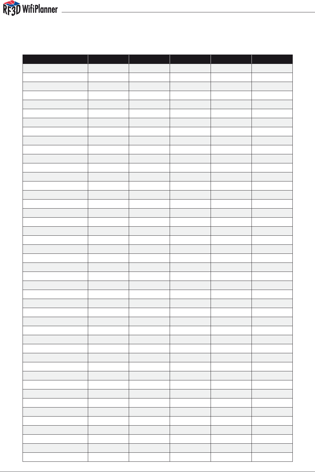
Appendix C Table of Colors
Color knownColor R G B A
Aqua 30 0 255 255 255
Aquamarine 31 127 255 212 255
Black 35 0 0 0 255
BlanchedAlmond 36 255 235 205 255
Blue 37 0 0 255 255
BlueViolet 38 138 43 226 255
Brown 39 165 42 42 255
BurlyWood 40 222 184 135 255
CadetBlue 41 95 158 160 255
Chartreuse 42 127 255 0 255
Chocolate 43 210 105 30 255
Coral 44 255 127 80 255
CornflowerBlue 45 100 149 237 255
Crimson 47 220 20 60 255
Cyan 48 0 255 255 255
DarkBlue 49 0 0 139 255
DarkCyan 50 0 139 139 255
DarkGoldenrod 51 184 134 11 255
DarkGray 52 169 169 169 255
DarkGreen 53 0 100 0 255
DarkKhaki 54 189 183 107 255
DarkMagenta 55 139 0 139 255
DarkOliveGreen 56 85 107 47 255
DarkOrange 57 255 140 0 255
DarkOrchid 58 153 50 204 255
DarkRed 59 139 0 0 255
DarkSalmon 60 233 150 122 255
DarkSeaGreen 61 143 188 139 255
DarkSlateBlue 62 72 61 139 255
DarkSlateGray 63 47 79 79 255
DarkTurquoise 64 0 206 209 255
DarkViolet 65 148 0 211 255
DeepPink 66 255 20 147 255
DeepSkyBlue 67 0 191 255 255
DimGray 68 105 105 105 255
DodgerBlue 69 30 144 255 255
Firebrick 70 178 34 34 255
ForestGreen 72 34 139 34 255
Fuchsia 73 255 0 255 255
Gold 76 255 215 0 255
Goldenrod 77 218 165 32 255
Gray 78 128 128 128 255
Green 79 0 128 0 255
GreenYellow 80 173 255 47 255

manual
39
HotPink 82 255 105 180 255
IndianRed 83 205 92 92 255
Indigo 84 75 0 130 255
Khaki 86 240 230 140 255
LawnGreen 89 124 252 0 255
LightBlue 91 173 216 230 255
LightCoral 92 240 128 128 255
LightGray 95 211 211 211 255
LightGreen 96 144 238 144 255
LightPink 97 255 182 193 255
LightSalmon 98 255 160 122 255
LightSeaGreen 99 32 178 170 255
LightSkyBlue 100 135 206 250 255
LightSlateGray 101 119 136 153 255
LightSteelBlue 102 176 196 222 255
Lime 104 0 255 0 255
LimeGreen 105 50 205 50 255
Magenta 107 255 0 255 255
Maroon 108 128 0 0 255
MediumAquamarine 109 102 205 170 255
MediumBlue 110 0 0 205 255
MediumOrchid 111 186 85 211 255
MediumPurple 112 147 112 219 255
MediumSeaGreen 113 60 179 113 255
MediumSlateBlue 114 123 104 238 255
MediumSpringGreen 115 0 250 154 255
MediumTurquoise 116 72 209 204 255
MediumVioletRed 117 199 21 133 255
MidnightBlue 118 25 25 112 255
Moccasin 121 255 228 181 255
NavajoWhite 122 255 222 173 255
Navy 123 0 0 128 255
Olive 125 128 128 0 255
OliveDrab 126 107 142 35 255
Orange 127 255 165 0 255
OrangeRed 128 255 69 0 255
Orchid 129 218 112 214 255
PaleGoldenrod 130 238 232 170 255
PaleGreen 131 152 251 152 255
PaleTurquoise 132 175 238 238 255
PaleVioletRed 133 219 112 147 255
PeachPuff 135 255 218 185 255
Peru 136 205 133 63 255
Pink 137 255 192 203 255
Plum 138 221 160 221 255
PowderBlue 139 176 224 230 255
Color knownColor R G B A
manual
40
Purple 140 128 0 128 255
Red 141 255 0 0 255
RosyBrown 142 188 143 143 255
RoyalBlue 143 65 105 225 255
SaddleBrown 144 139 69 19 255
Salmon 145 250 128 114 255
SandyBrown 146 244 164 96 255
SeaGreen 147 46 139 87 255
Sienna 149 160 82 45 255
Silver 150 192 192 192 255
SkyBlue 151 135 206 235 255
SlateBlue 152 106 90 205 255
SlateGray 153 112 128 144 255
SpringGreen 155 0 255 127 255
SteelBlue 156 70 130 180 255
Tan 157 210 180 140 255
Teal 158 0 128 128 255
Thistle 159 216 191 216 255
Tomato 160 255 99 71 255
Turquoise 161 64 224 208 255
Violet 162 238 130 238 255
White 164 255 255 255 255
Yellow 166 255 255 0 255
YellowGreen 167 154 205 50 255
Anhang D EULA
PSIBER DATA END USER SOFTWARE LICENSE AGREEMENT
IF YOU DO NOT AGREE, DO NOT USE THIS SOFTWARE.
This Software Agreement („Agreement“) is between You (either an individual or an entity), the
End User, and Psiber Data GmbH („Psiber“). The Agreement authorizes you to use the Software
specified in Clause 1 below, which may be stored on physical media, sent to You by electronic
mail, downloaded from Psiber‘s Web pages or Servers or from other sources under the terms and
conditions set forth below. This is an agreement on end user rights and not an agreement for sale
or resale. Psiber continues to own the copy of the Software and the physical media contained in
the sales package and any other copy that You are authorised to make pursuant to this Agree-
ment.
Read this Agreement carefully before installing, downloading or using the Software. By using, cop-
ying or distributing all or any portion of the Psiber Software, You agree to the terms and conditions
of this Agreement. If You do not agree to all of the terms and conditions of this Agreement then
do not use this software, cancel the installation or downloading, or destroy or return the Software
and accompanying documentation to Psiber. YOU AGREE THAT YOUR USE OF THE SOFTWARE AC-
KNOWLEDGES THAT YOU HAVE READ THIS AGREEMENT, UNDERSTAND IT, AND AGREE TO BE BOUND
BY ITS TERMS AND CONDITIONS.
Color knownColor R G B A

manual
41
1. DEFINITIONS
As used in this Agreement, the term „Software“ means, collectively: (i) all of the contents of the
les (provided either by electronic download, on physical media or any other method of distribu-
tion), disk(s), CD/DVD-ROM(s) or other media with which this Agreement is provided, (ii) all the
contents of the disk(s), CD-ROM(s), electronic mail and its le attachments, including the object
code form of the software delivered on physical media, electronic mail or Web page (iii) digital
images, stock photographs, clip art, or other artistic work („Stock Files“) (iv) related explanatory
written materials and any other possible documentation related thereto („Documentation“); (v)
fonts (vi) upgrades, modied versions, updates, additions (collectively „Updates“), if any, licensed
to You by Psiber under this Agreement.
„Use“ or „Using“ means to access, install, download, copy, or otherwise benet from using the
functionality of the Software in accordance with the Documentation. „Permitted Number“ means
one (1) unless otherwise indicated under a valid license (e.g., volume license) granted by Psiber.
„Computer“ means an electronic device that accepts information in digital or similar form and
manipulates it for a specific result
based on a sequence of instructions.
2. END USER RIGHTS AND USE.
Psiber grants to You a non-exclusive, non-transferable end user right to install the Software on the
local hard disk(s) of one computer or other permanent storage media including a computer le
server within your internal network and use the Software on a single computer or terminal at a
time.
3. LIMITATIONS ON END USER RIGHTS.
You may not copy, distribute, or make derivative works of the Software except as follows:
(a) You may make one copy of the Software on physical media as an archival backup copy,
provided Your archival backup copy is not installed or used on any computer. Any other copies
You make of the Software are in violation of this Agreement.
(b) You may not use, modify, translate, reproduce or transfer the right to use the Software or copy
the Software except as expressly provided in this Agreement.
(c) You may not resell, sublicense, rent, lease, lend the Software assign or transfer your rights in the
Software, or authorize all or any portion of the Software to be copied onto another user‘s Com-
puter except as may be expressly permitted herein.
You may, however, transfer all your rights to Use the Software to another person or legal entity
provided that: (a) you also transfer (i) this Agreement, and (ii) the Software and all other software
or hardware bundled or pre-installed with the Software, including all copies, Updates and prior
versions, to such person or entity, (b) you retain no copies, including backups and copies stored
on a Computer, and (c) the receiving party accepts the terms and conditions of this Agreement
and any other terms and conditions upon which you legally purchased a license to the Software.
Notwithstanding the foregoing, you may not transfer education, pre-release, or not for resale cop-
ies of the Software.
(d) You may not reverse engineer, reverse compile, disassemble or otherwise attempt to discover

manual
42
the source code of the Software (except to the extent that this restriction is expressly prohibited
by law) or create derivative works based on the Software.
(e) Unless stated otherwise in the Documentation, You shall not display, modify, reproduce and
distribute any of the Stock Files included with the Software. In the event that the Documentation
allows You to display the Stock Files, You shall not distribute the Stock Files on a stand-alone basis,
i.e., in circumstances in which the Stock Files constitute the primary value of the product being
distributed. You should review the „Read-Me“ les associated with the Stock Files that You use to
ascertain what rights You have with respect to such materials. Stock Files may not be used in the
production of libelous, defamatory, fraudulent, infringing, lewd, obscene or pornographic mate-
rial or in any otherwise illegal manner. You may not register or claim any rights in the Stock Files or
derivative works thereof.
(f) You agree that You shall only use the Software in a manner that complies with all applicable
laws in the jurisdiction in which You use the Software, including, but not limited to, applicable re-
strictions concerning copyright and other intellectual property rights.
4. COPYRIGHT, INTELLECTUAL PROPERTY OWNERSHIP.
The Software and all rights, without limitation including proprietary rights therein, are owned by
Psiber and/or its licensors and affiliates and are protected by international treaty provisions and
all other applicable national laws of the country in which it is being used. The structure, organi-
zation and code of the Software are the intellectual property, valuable trade secrets and con-
fidential information of Psiber and/or its licensors and affiliates. You must not copy the Software,
except as set forth in clause 3 (Limitations On End User Rights). Any copies which You are permit-
ted to make pursuant to this Agreement must contain the same copyright and other proprietary
notices that appear on the Software. Psiber permits you to Use the Software only in accordance
with the terms of this Agreement. Use of some third party materials included in the Software may
be subject to other terms and conditions typically found in a separate license agreement.
5. MULTIPLE ENVIRONMENT SOFTWARE / MULTIPLE LANGUAGE SOFTWARE / DUAL MEDIA SOFTWARE /
MULTIPLE COPIES / UPDATES.
If the Software supports multiple platforms or languages, if You receive the Software on multiple
media, of if You otherwise receive multiple copies of the Software, the number of computers on
which all versions of the Software are installed shall be one computer. You may not rent, lease,
sublicense, lend or transfer versions or copies of the Software You do not use. If the Software is an
Update to a previous version of the Software, You must possess a valid end user right to such previ-
ous version in order to use the Update and You may use the previous version for ninety (90) days
after you receive the Update in order to assist You in the transition to the Update. After such time
You no longer have a right to use the previous version, except for the sole purpose of enabling
You to install the Update.
6. COMMENCEMENT & TERMINATION.
This Agreement is effective from the first date You install the Software. You may terminate this
Agreement at any time by permanently deleting, destroying and returning, at your own costs,
the Software, all back up copies and all related materials provided by Psiber. Your end user rights
automatically and immediately terminate without notice from Psiber if You fail to comply with
any provision of this Agreement. In such event, You must immediately delete, destroy or return at
Your own cost, the Software, all backup copies and all related material to Psiber.
7. YOU ACKNOWLEDGE THAT THE SOFTWARE IS PROVIDED „AS IS“ WITHOUT WARRANTY OF ANY

manual
43
KIND, EXPRESS OR IMPLIED, AND TO THE MAXIMUM EXTENT PERMITTED BY APPLICABLE LAW NEITHER
PSIBER ITS LICENSORS OR AFFILIATES NOR THE COPYRIGHT HOLDERS MAKE ANY REPRESENTATIONS
OR WARRANTIES, EXPRESS OR IMPLIED, INCLUDING BUT NOT LIMITED TO THE WARRANTIES OF MER-
CHANTABILITY OR FITNESS FOR A PARTICULAR PURPOSE OR THAT THE SOFTWARE WILL NOT INFRINGE
ANY THIRD PARTY PATENTS, COPYRIGHTS, TRADEMARKS OR OTHER RIGHTS. THERE IS NO WARRANTY
BY PSIBER OR BY ANY OTHER PARTY THAT THE FUNCTIONS CONTAINED IN THE SOFTWARE WILL MEET
YOUR REQUIREMENTS OR THAT THE OPERATION OF THE SOFTWARE WILL BE UNINTERRUPTED OR ER-
ROR-FREE. YOU ASSUME ALL RESPONSIBILITY AND RISK FOR THE SELECTION OF THE SOFTWARE TO
ACHIEVE YOUR INTENDED RESULTS AND FOR THE INSTALLATION, USE AND RESULTS OBTAINED FROM
IT.
LIMITED WARRANTY FOR USERS RESIDING IN GERMANY OR AUSTRIA. If you obtained the Software
in Germany or Austria, and you usually reside in such country, then the paragraph above under
Section 7 does not apply, instead, Psiber warrants that the Software provides the functionalities
set forth in the Documentation (the „agreed upon functionalities“) for the limited warranty pe-
riod following receipt of the Software when used on the recommended hardware configuration.
As used in this Section, „limited warranty period“ means one (1) year if you are a business user
and two (2) years if you are not a business user. Non-substantial variation from the agreed upon
functionalities shall not be considered and does not establish any warranty rights. THIS LIMITED
WARRANTY DOES NOT APPLY TO SOFTWARE PROVIDED TO YOU FREE OF CHARGE, FOR EXAMPLE,
UPDATES, PRE-RELEASE, TRYOUT, PRODUCT SAMPLER, NOT FOR RESALE (NFR) COPIES OF SOFTWARE,
OR SOFTWARE THAT HAS BEEN ALTERED BY YOU, TO THE EXTENT SUCH ALTERATIONS CAUSED A DE-
FECT. To make a warranty claim, during the limited warranty period you must return, at our ex-
pense, the Software and proof of purchase to the location where you obtained it. If the function-
alities of the Software vary substantially from the agreed upon functionalities, Psiber is entitled
-- by way of re-performance and at its own discretion -- to repair or replace the Software. If this
fails, you are entitled to a reduction of the purchase price (reduction) or to cancel the purchase
agreement (rescission).
The provisions of Section 7 and Section 9 shall survive the termination of this Agreement, how-
soever caused, but this shall not imply or create any continued right to Use the Software after
termination of this Agreement.
8. NO OTHER OBLIGATIONS.
This Agreement creates no obligations on the part of Psiber other than as specifically set forth
herein.
9. LIMITATION OF LIABILITY.
TO THE MAXIMUM EXTENT PERMITTED BY APPLICABLE LAW, IN NO EVENT SHALL PSIBER, ITS EMPLOY-
EES OR LICENSORS OR AFFILIATES BE LIABLE FOR ANY DAMAGES, CLAIMS OR COSTS, ANY LOST
PROFITS, REVENUE, SALES, DATA OR COSTS OF PROCUREMENT OF SUBSTITUTE GOODS OR SERVICES,
PROPERTY DAMAGE, PERSONAL INJURY, INTERRUPTION OF BUSINESS, LOSS OF BUSINESS INFORMA-
TION OR FOR ANY SPECIAL, DIRECT, INDIRECT, INCIDENTAL, ECONOMIC, COVER, PUNITIVE, SPECIAL
OR CONSEQUENTIAL DAMAGES, HOWEVER CAUSED AND WHETHER ARISING UNDER CONTRACT,
TORT, NEGLIGENCE, OR OTHER THEORY OF LIABILITY ARISING OUT OF THE USE OF OR INABILITY TO
USE THE SOFTWARE, EVEN IF PSIBER OR ITS LICENSORS OR AFFILIATES ARE ADVISED OF THE POSSIBIL-
ITY OF SUCH DAMAGES. BECAUSE SOME COUNTRIES/STATES/JURISDICTIONS DO NOT ALLOW THE
EXCLUSION OR LIMITATION OF LIABILITY, BUT MAY ALLOW LIABILITY TO BE LIMITED, IN SUCH CASES,
PSIBER, ITS EMPLOYEES OR LICENSORS OR AFFILIATES‘ LIABILITY SHALL BE LIMITED TO U.S. $50.

manual
44
Nothing contained in this Agreement shall prejudice the statutory rights of any party dealing as a
consumer. Nothing contained in this Agreement limits Psiber‘s liability to You in the event of death
or personal injury resulting from Psiber‘s negligence. Psiber is acting on behalf of its employees
and licensors or affiliates for the purpose of disclaiming, excluding and/or restricting obligations,
warranties and liability as provided in this clause 9, but in no other respects and for no other pur-
pose.
IF YOU OBTAINED THE SOFTWARE IN GERMANY OR AUSTRIA, and you usually reside in such coun-
try, then the paragraphs above under Section 9 do not apply. Instead, Psiber‘s statutory liability
for damages shall be limited as follows: (i) Psiber shall be liable only up to the amount of dam-
ages as typically foreseeable at the time of entering into the purchase agreement in respect
of damages caused by a slightly negligent breach of a material contractual obligation and (ii)
Psiber shall not be liable for damages caused by a slightly negligent breach of a non-material
contractual obligation. The aforesaid limitation of liability shall not apply to any mandatory statu-
tory liability, in particular, to liability under the German Product Liability Act, liability for assuming
a specific guarantee or liability for culpably caused personal injuries. You are required to take all
reasonable measures to avoid and reduce damages, in particular to make back-up copies of
the Software and your computer data subject to the provisions of this Agreement.
10. TECHNICAL SUPPORT.
Psiber has no obligation to furnish You with technical support unless separately agreed in writing
between You and Psiber.
11. EXPORT CONTROL.
You agree that the Software will not be shipped, transferred or exported into any country or used
in any manner prohibited by the United States Export Administration Act or any other export laws,
restrictions or regulations (collectively the „Export Laws“). In addition, if the Software is identied
as export controlled items under the Export Laws, you represent and warrant that you are not a
citizen, or otherwise located within, an embargoed nation (including without limitation Iran, Syria,
Sudan, Libya, Cuba, and North Korea) and that you are not otherwise prohibited under the Export
Laws from receiving the Software. All rights to Use the Software are granted on condition that
such rights are forfeited if you fail to comply with the terms of this Agreement.
The Software, including technical data, may be subject to export controls under the U.S. Export
Administration Regulations („EAR“) and to import or export controls in other countries. The EAR
prohibits the use of the Software and technical data by a Government End-User, as defined here-
after, without a license from the U.S. government. A Government End-User is defined in Part 772 of
the EAR as „any foreign central, regional or local government department, agency or other entity
performing governmental functions; including governmental research institutions, governmental
Data corporations or their separate business units (as dened in part 772 of the EAR) which are
engaged in the manufacture or distribution of items or services controlled on the Wassenaar
Munitions List, and international governmental organizations. This term does not include: utilities
(telecommunications companies and Internet service providers; banks and nancial institutions;
transportation; broadcast or entertainment; educational organizations; civil health and medical
organizations; retail or wholesale firms; and manufacturing or industrial entities not engaged in
the manufacture or distribution of items or services controlled on the Wassenaar Munitions List.)“
You agree to comply strictly with all applicable import and export regulations and acknowledge
that You have the responsibility to obtain licenses to export, re-export, transfer or import the Soft-
ware. You further represent that You are not a Government End User as defined above, and You
will not transfer the Software to any Government End user without a license.

manual
45
12. NOTICES.
All notices and return of the Software and Documentation should be delivered to:
Psiber Data GmbH or PSIBER DATA SYSTEMS INC.
Felix-Wankel-Str. 4 7075-K Mission Gorge Road
D-82152 Krailling San Diego, CA 92120
GERMANY UNITED STATES OF AMERICA
13. APPLICABLE LAW & GENERAL PROVISIONS.
This Agreement will be governed by and construed in accordance with the substantive laws in
force: (a) in the State of California, if a license to the Software is obtained when you are in the
United States, Canada, or Mexico; or (b) Germany, if a license to the Software is purchased when
you are in any other jurisdiction not described above. The respective courts shall each have
non-exclusive jurisdiction over all disputes relating to this Agreement. This Agreement will not be
governed by the conflict of law rules of any jurisdiction or the United Nations Convention on Con-
tracts for the International Sale of Goods, the application of which is expressly excluded.
If any part of this Agreement is found void and unenforceable, it will not affect the validity of the
balance of the Agreement, which shall remain valid and enforceable according to its terms. This
Agreement may only be modified by a writing signed by an authorized officer of Psiber, although
Psiber may vary the terms of this Agreement.
This is the entire agreement between Psiber and You relating to the Software and it supersedes
any prior representations, discussions, undertakings, end user agreements, communications or
advertising relating to the Software.
If you have any questions regarding this Agreement or if you wish to request any information from
Psiber please use the address and contact information included with this product or via the web
at www.psiber.com to contact the Psiber office serving your jurisdiction
Psiber, RF3D are either registered trademarks or trademarks of Psiber Data GmbH in Europe or
Psiber Data Systems Incorporated in the United States and/or other countries.
PLEASE SUBMIT ANY ACCOMPANYING REGISTRATION FORMS TO RECEIVE REGISTRATION BENEFITS
WHERE APPLICABLE
manual
46
Handbuch
für RF3D WifiPlanner und
RF3D WifiPlanner Lite
For more information or
updates please contact:
www.RF3D.com
Psiber USA:
PSIBER DATA SYSTEMS Inc.
7075-K Mission Gorge Road
San Diego, CA 92120
phone 1-619-287-9970
fax 1-619-287-9978
E-mail info@psiber.com
Psiber Europe:
PSIBER DATA GmbH
Felix-Wankel-Straße 4
D-82152 Krailling
Tel +49 (0) 89 89 13 60 - 60
Fax +49 (0) 89 89 13 60 - 66
E-Mail info@psiber-data.com
