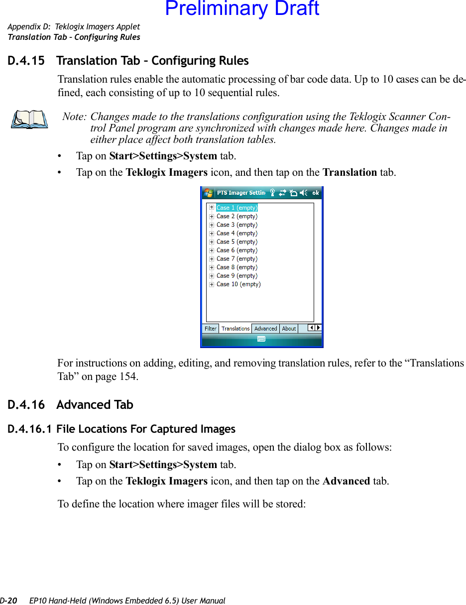
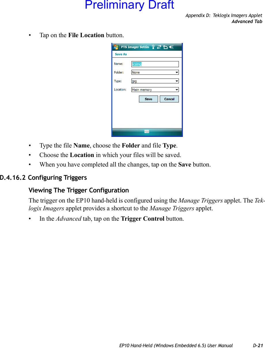
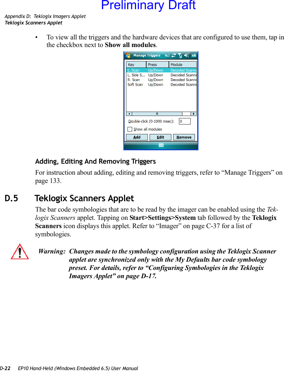
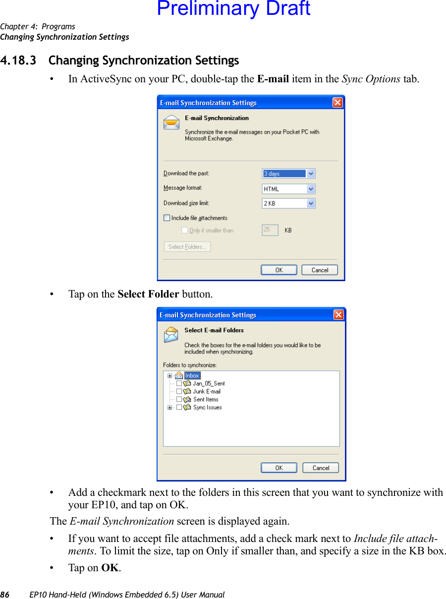
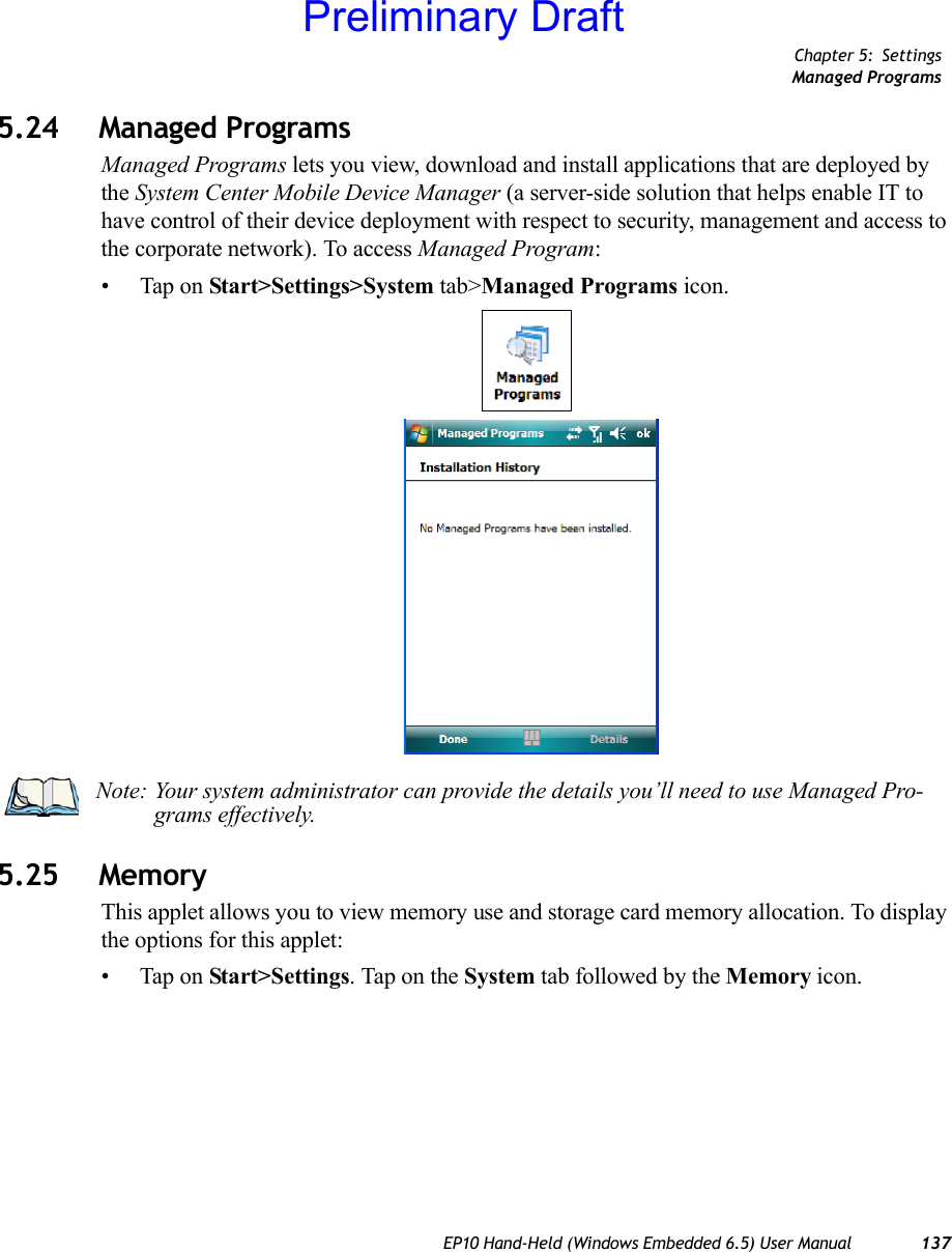
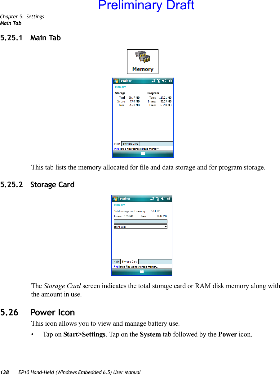
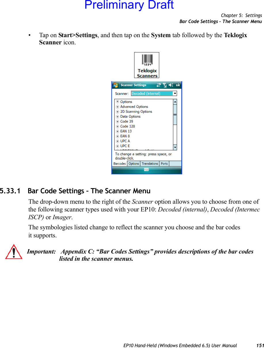
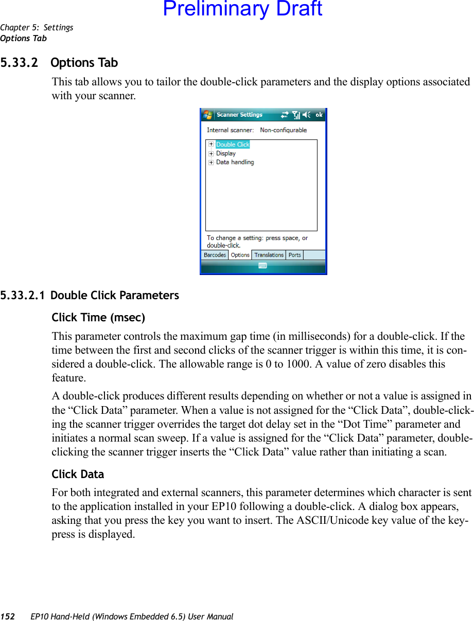
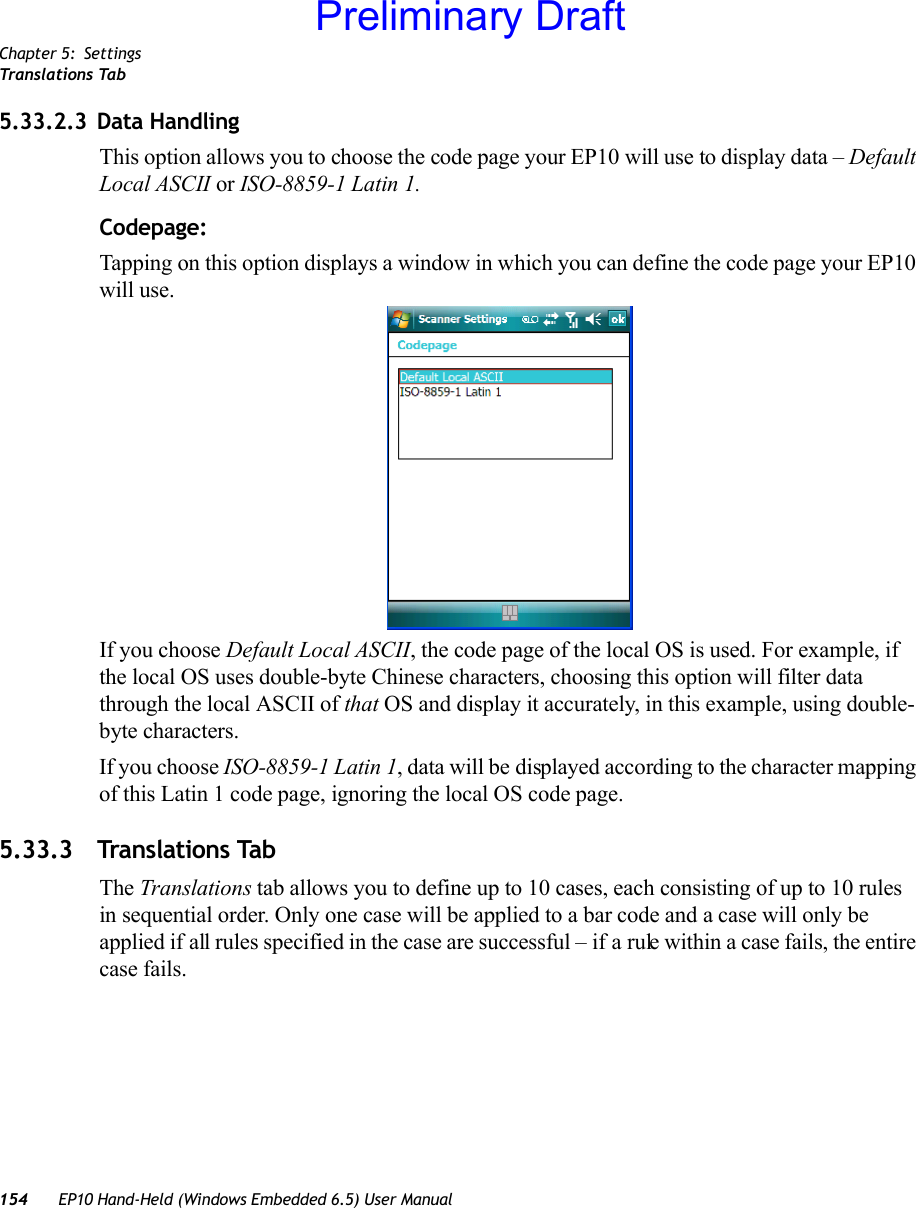
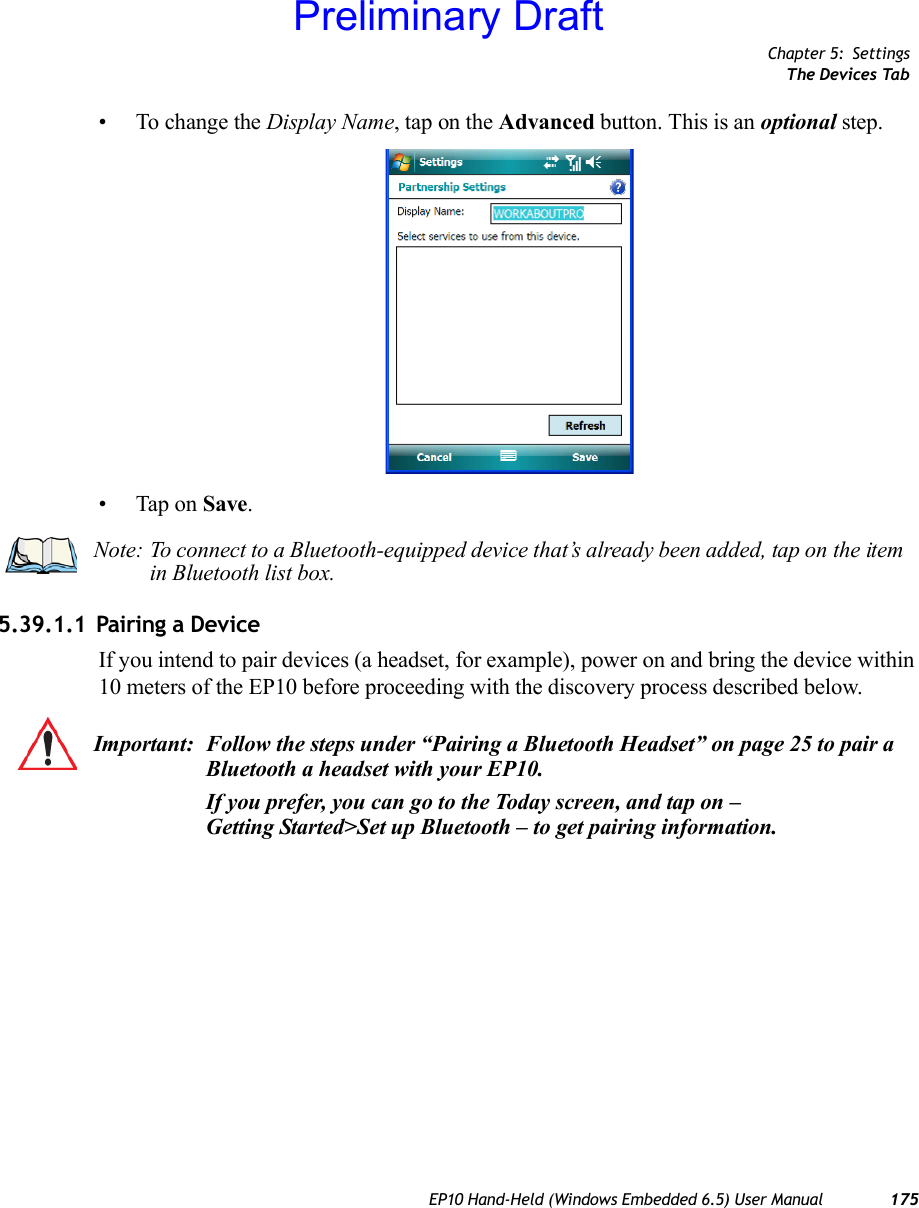
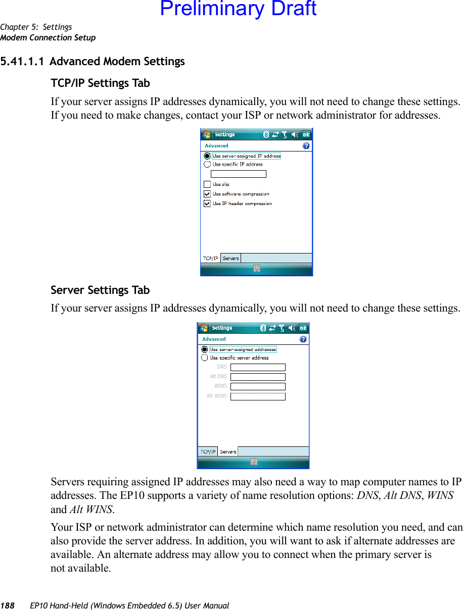
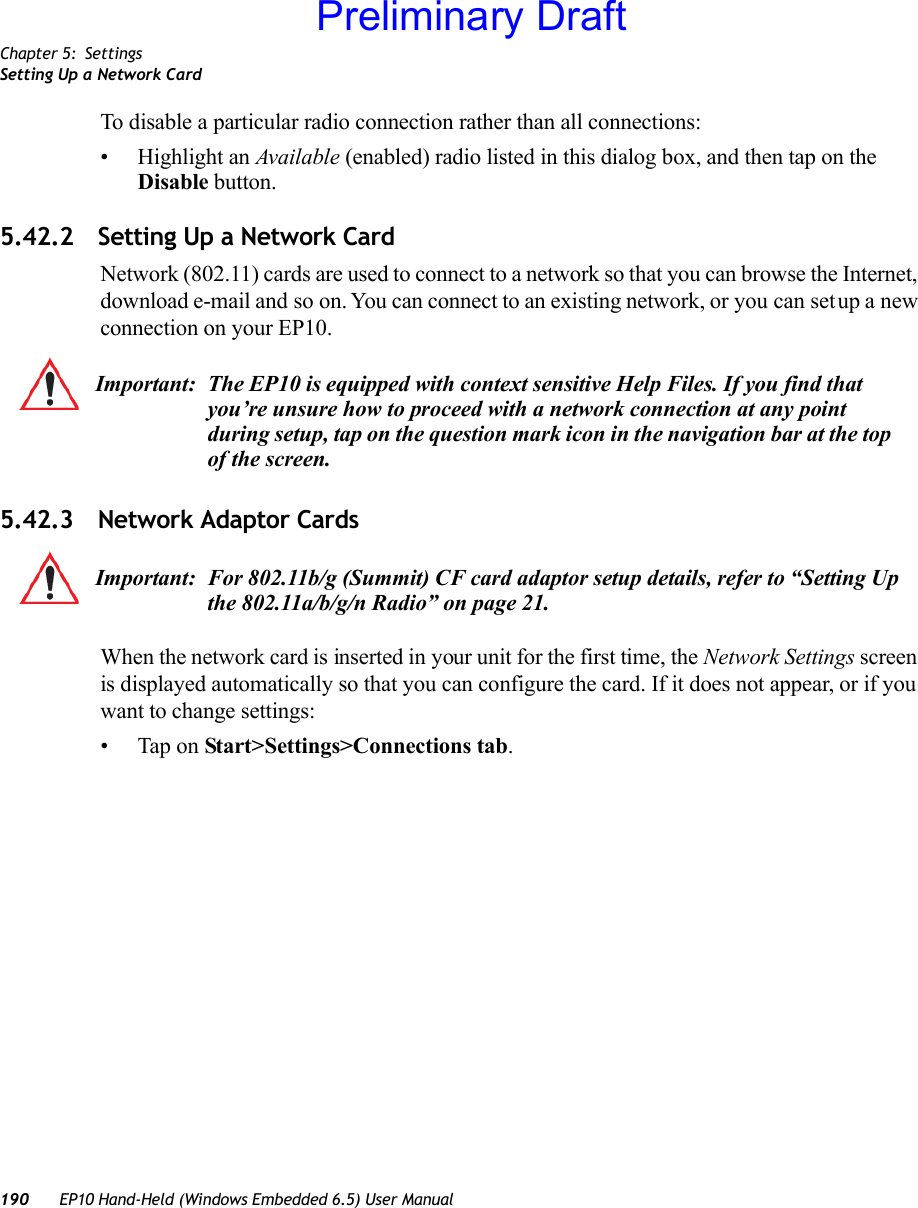
Psion 7515CA EP10 Hand-Held Computer User Manual EP10 Hand Held Computer with Windows Embedded
Psion Inc EP10 Hand-Held Computer EP10 Hand Held Computer with Windows Embedded
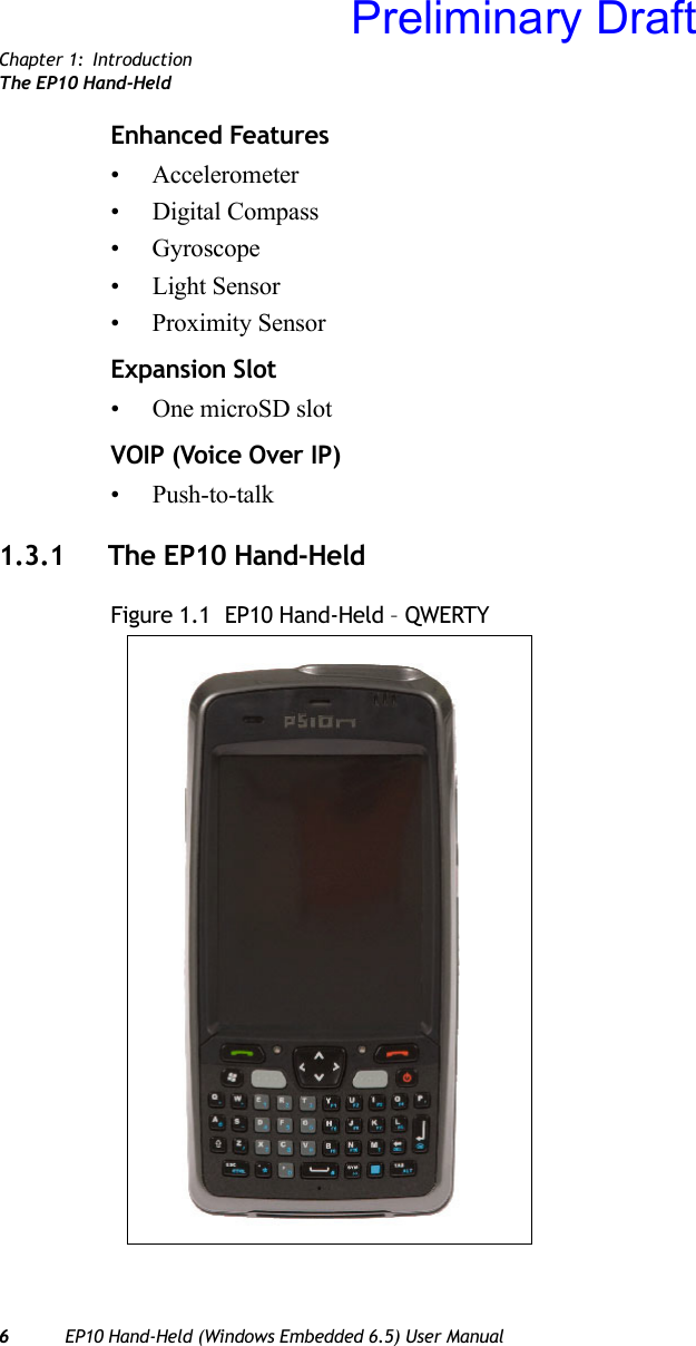
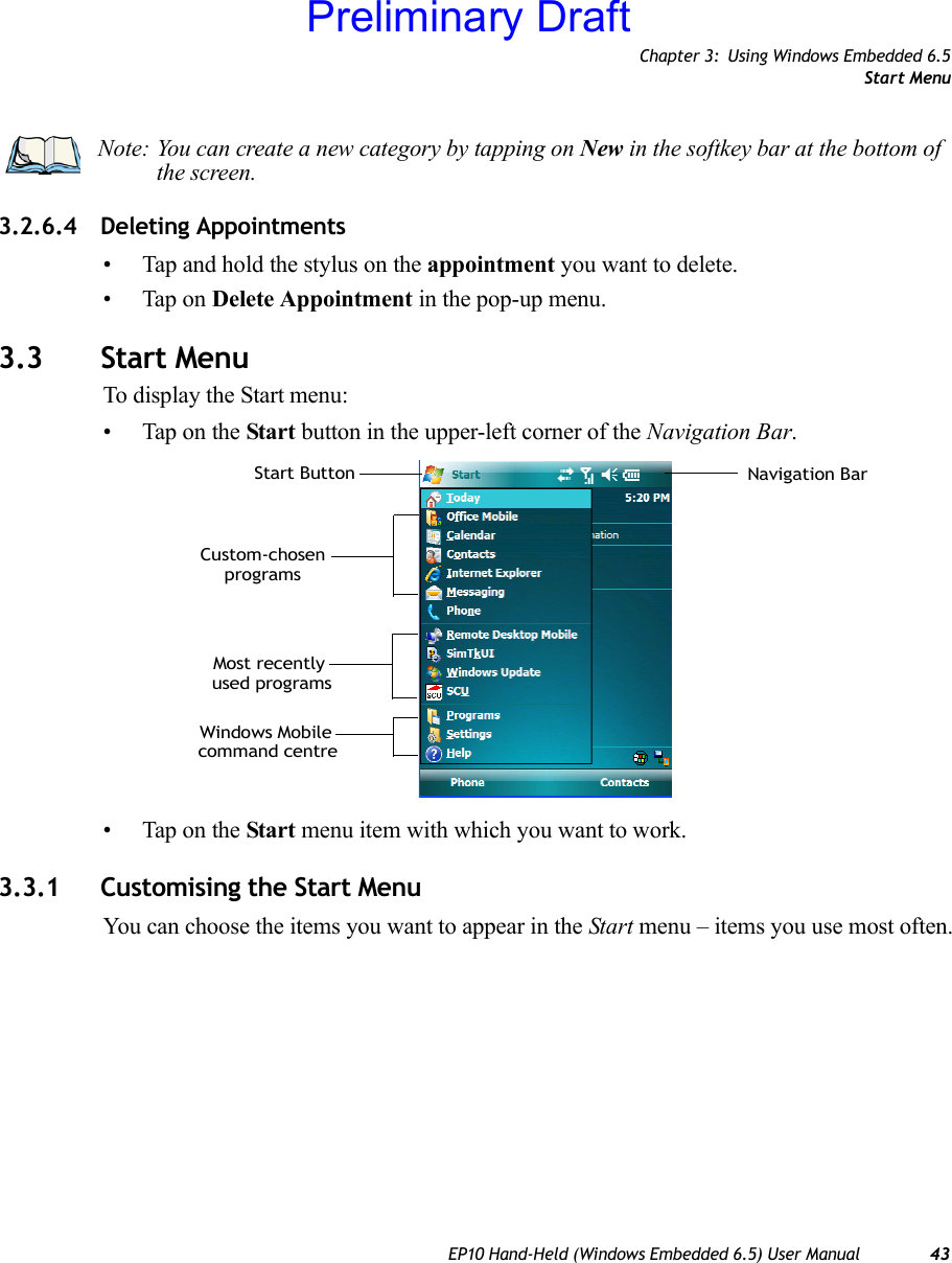
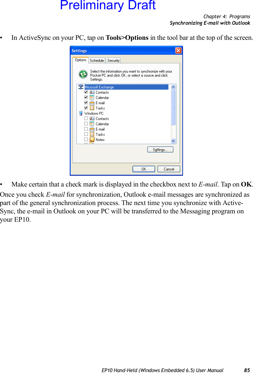
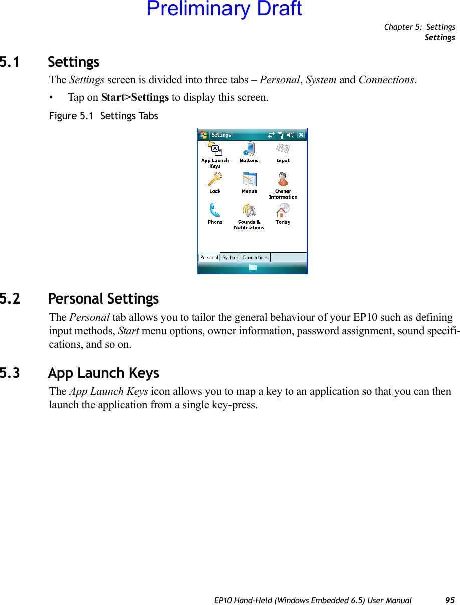
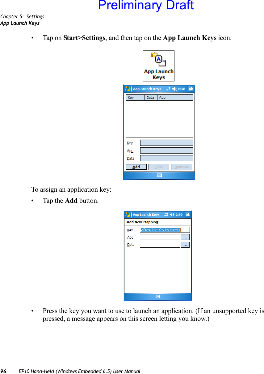
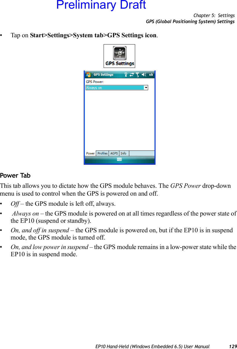
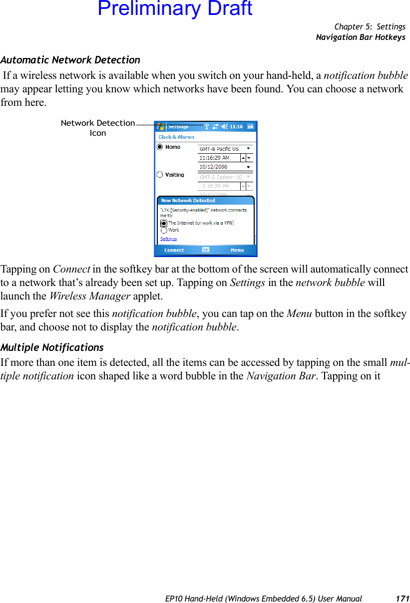
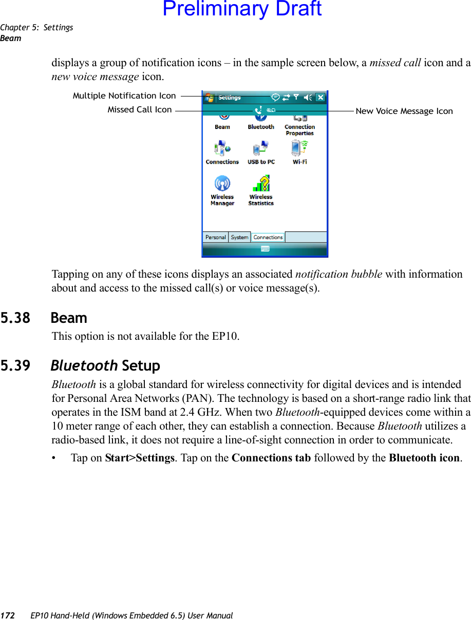
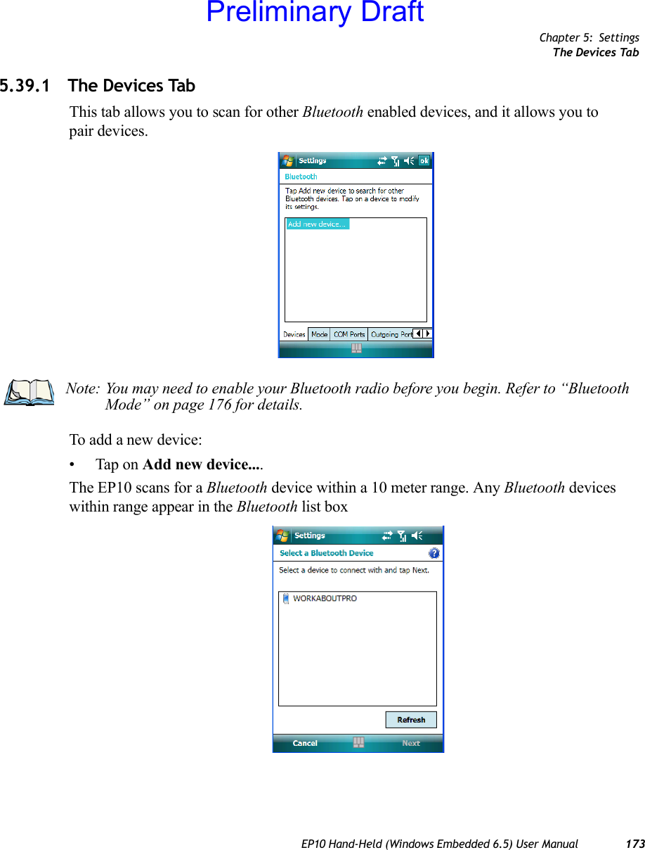
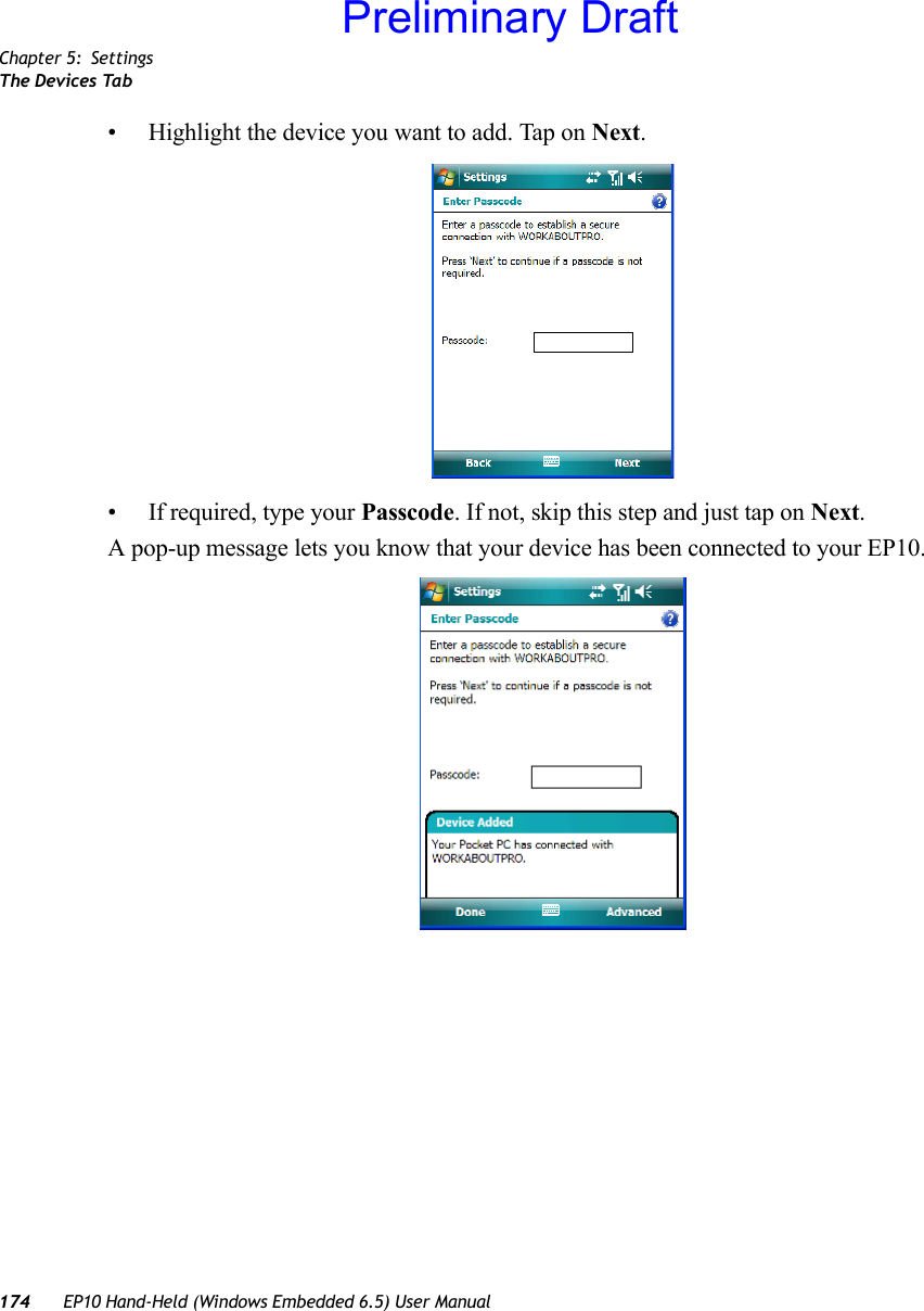
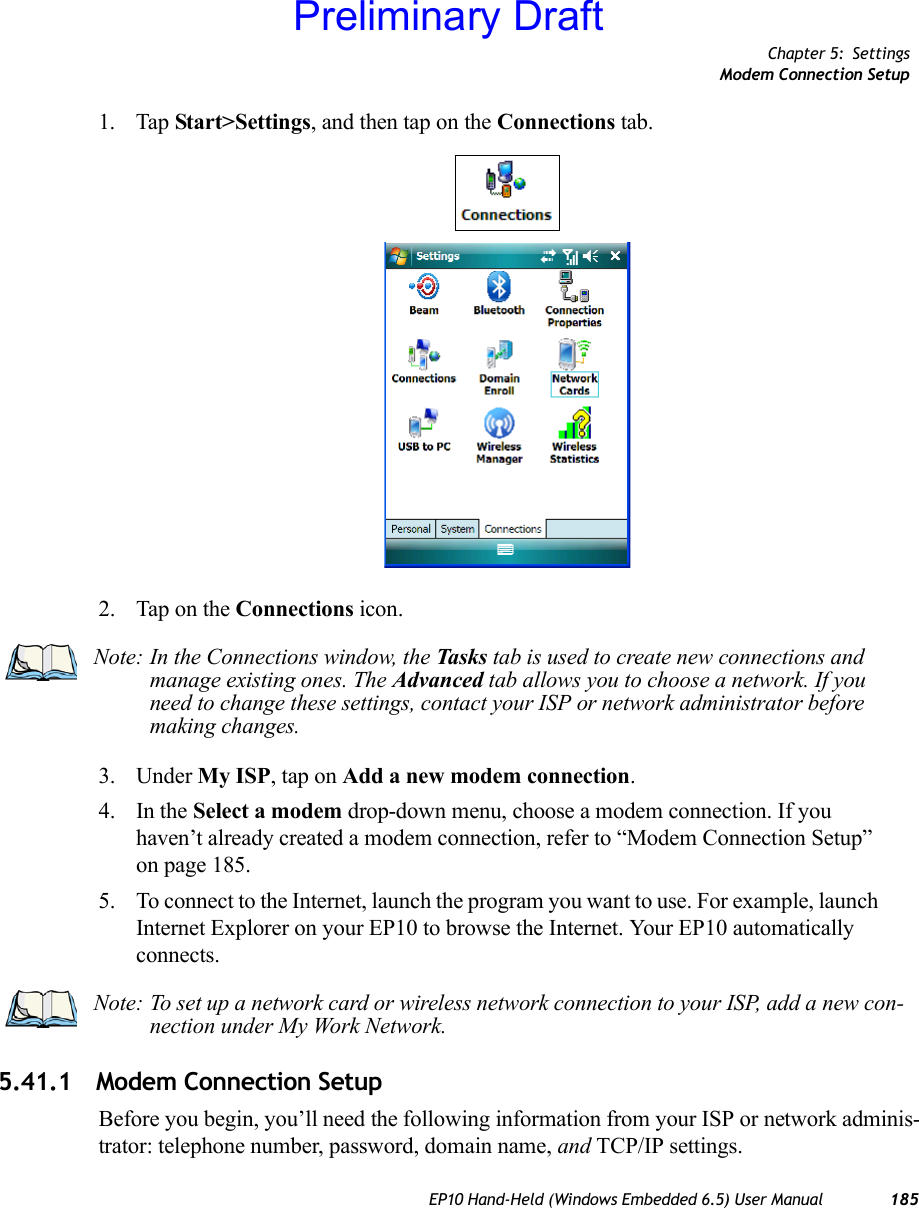
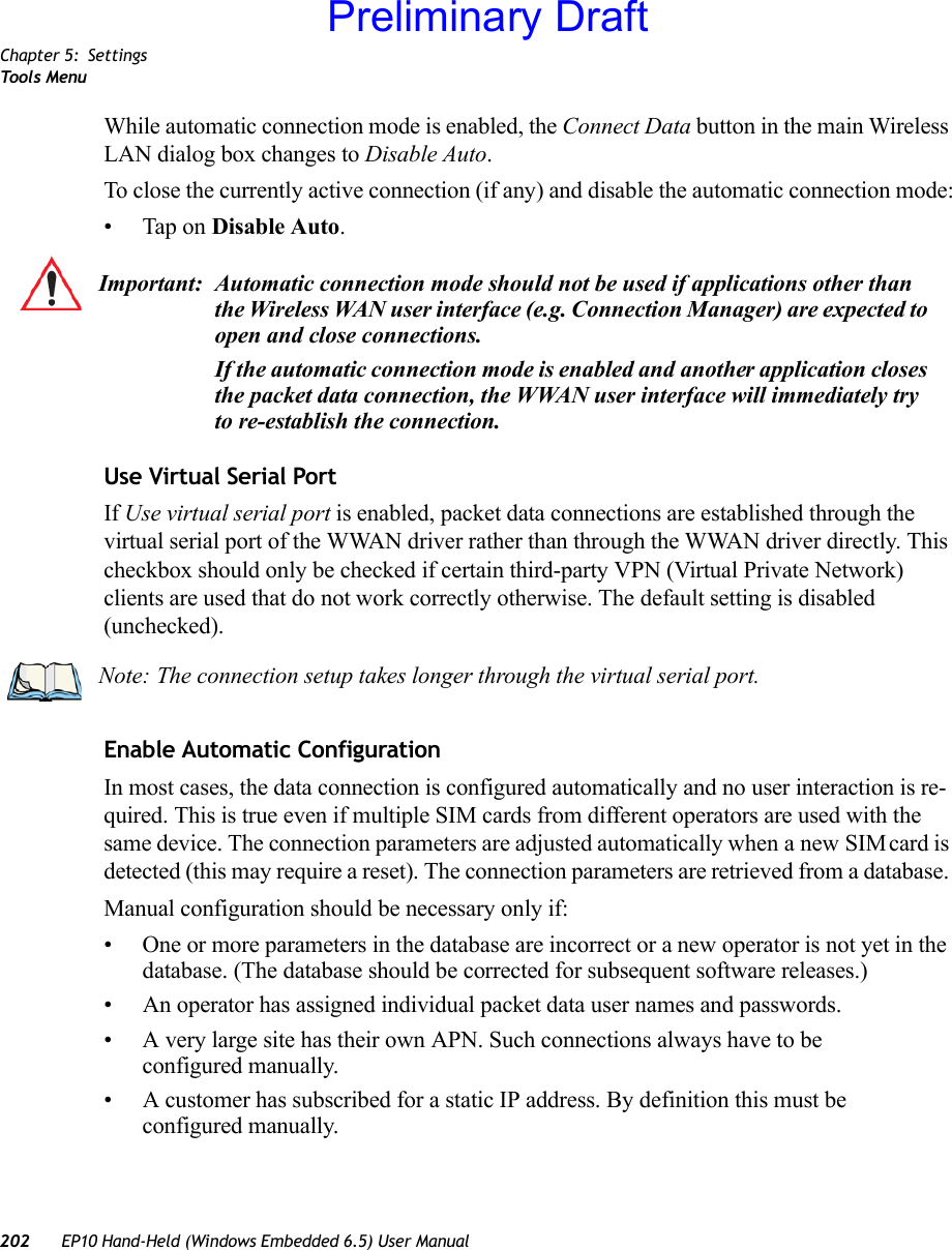
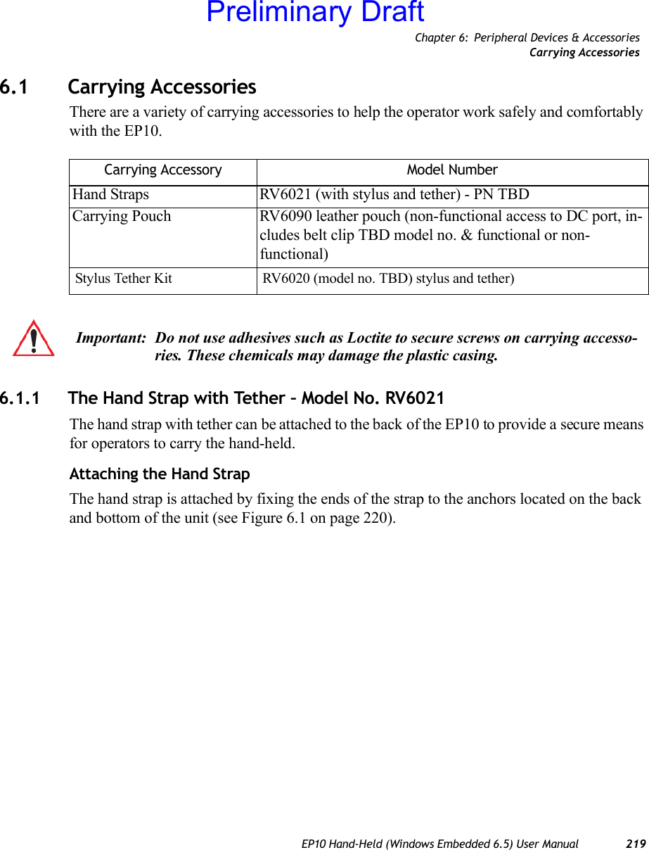
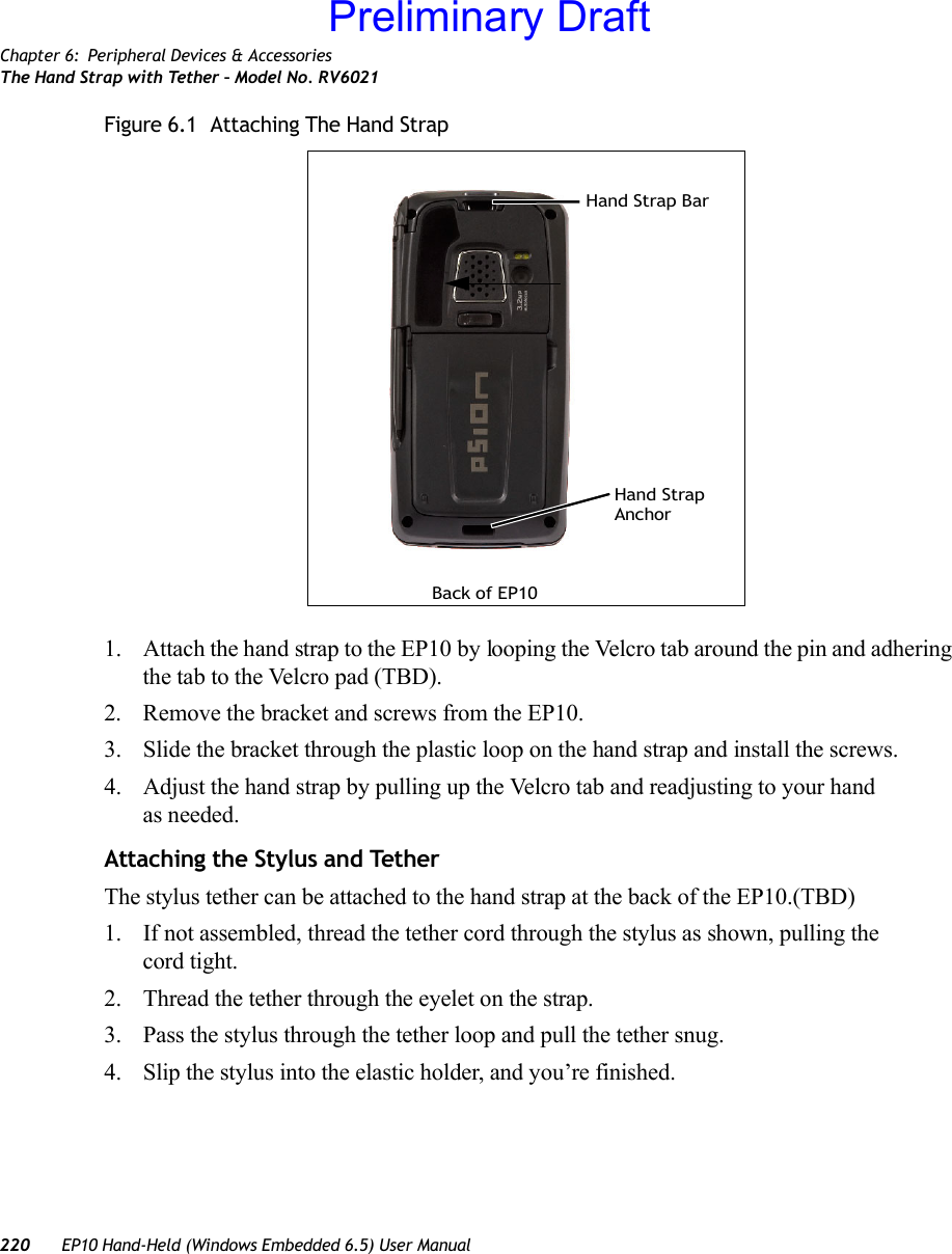
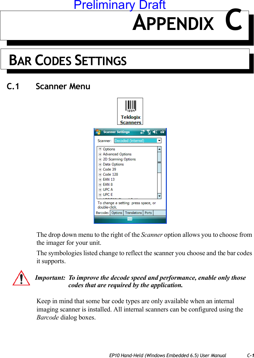
Psion >
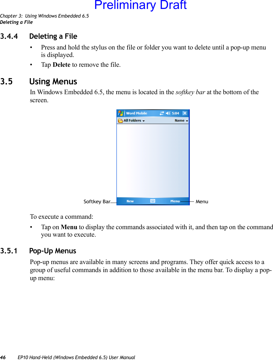
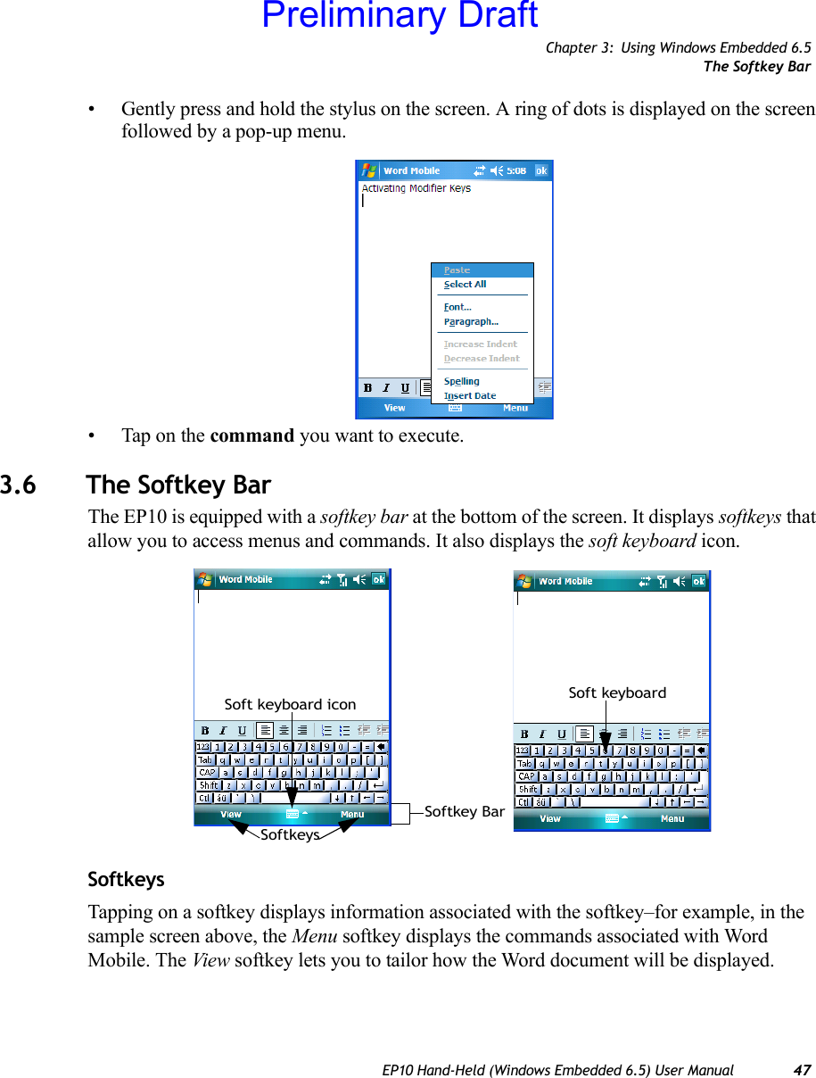
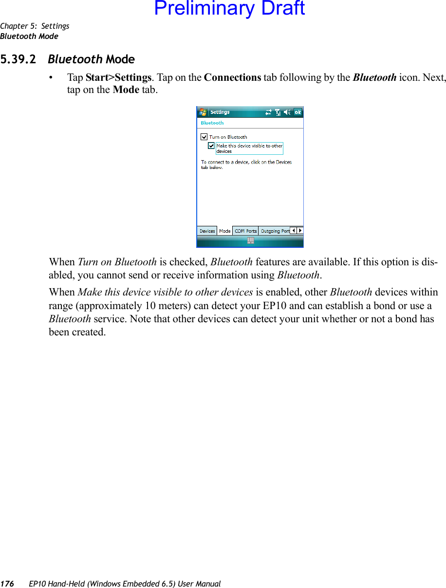
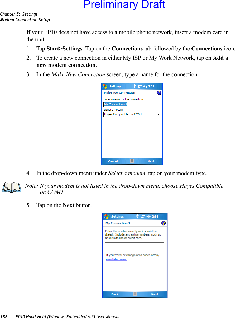
Contents
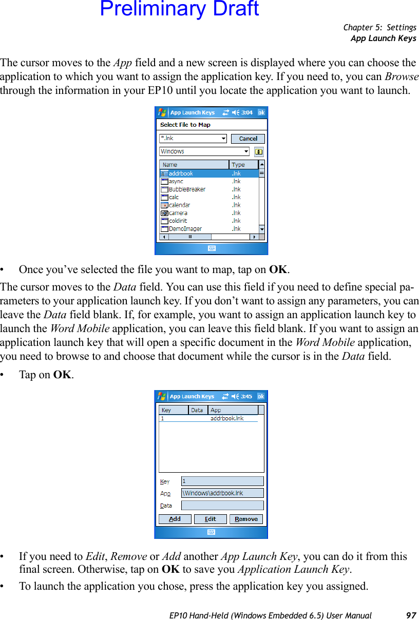
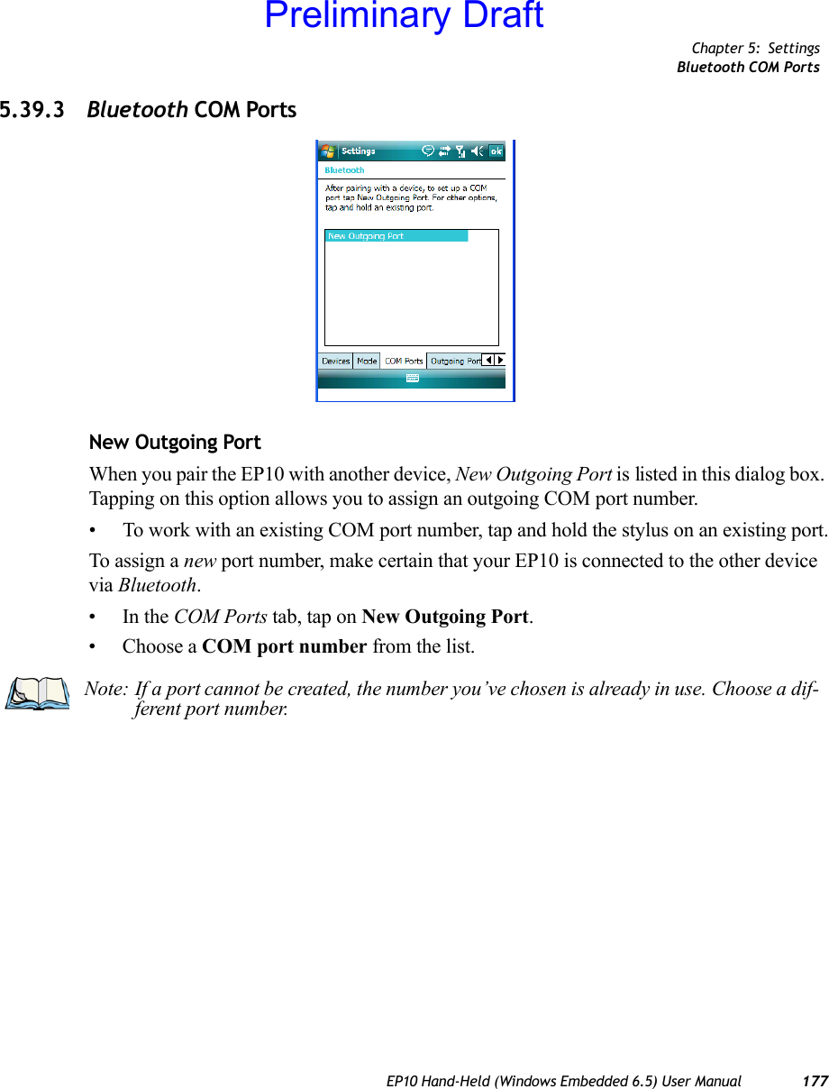
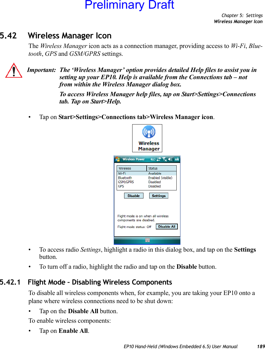
- 1. Users Manual
- 2. user manual 1
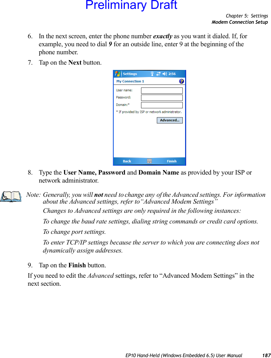
- 3. user manual 2
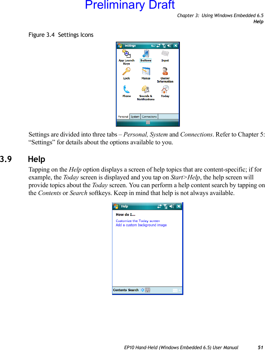
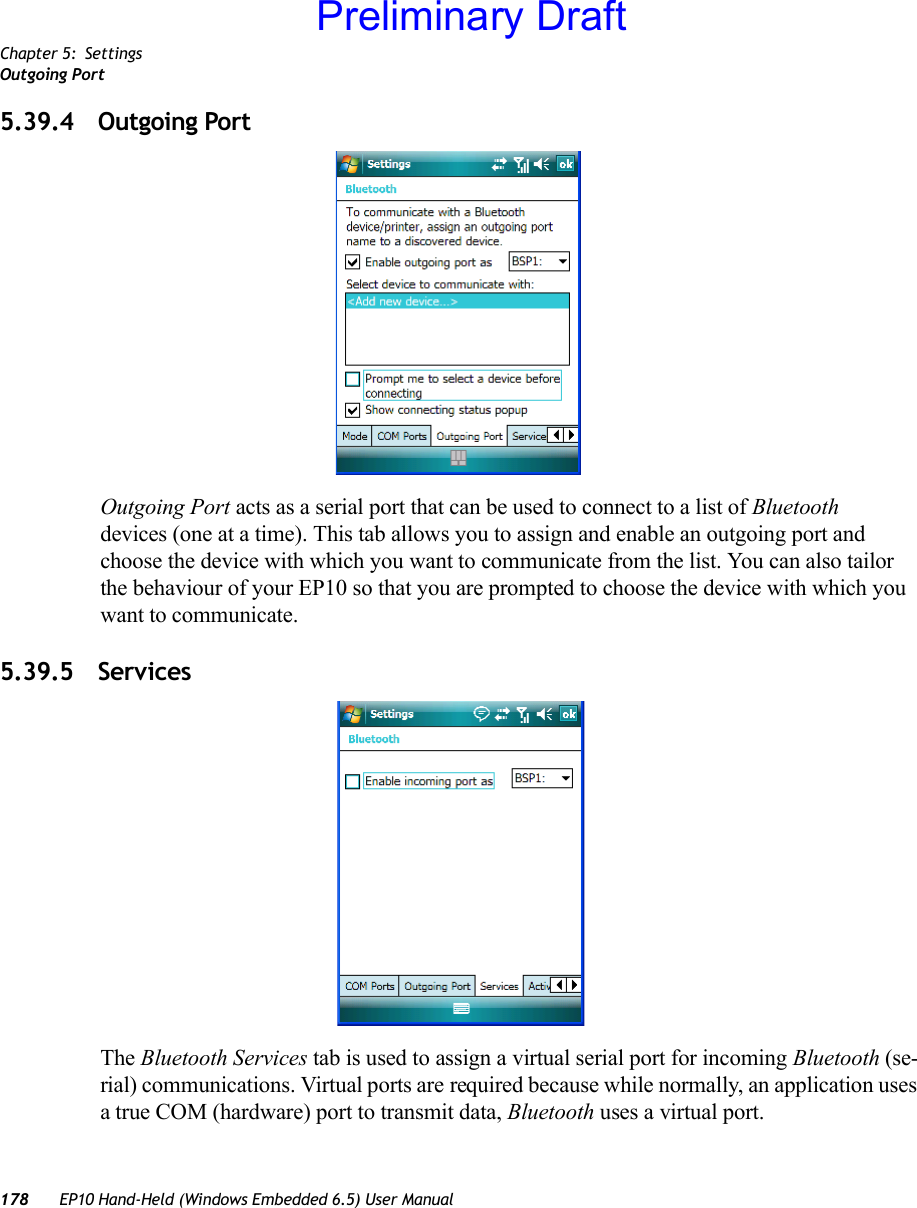
- 4. user manual
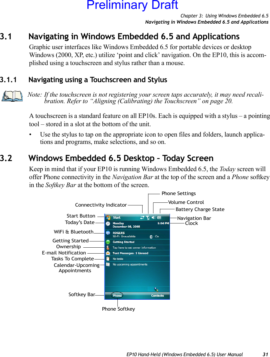
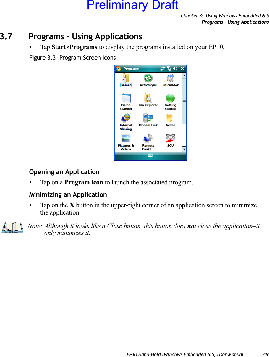
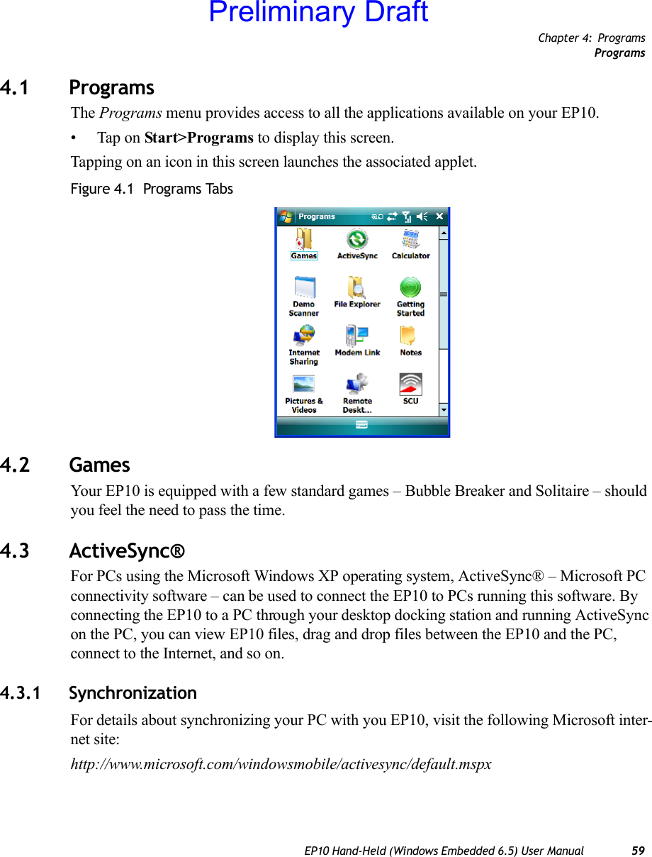
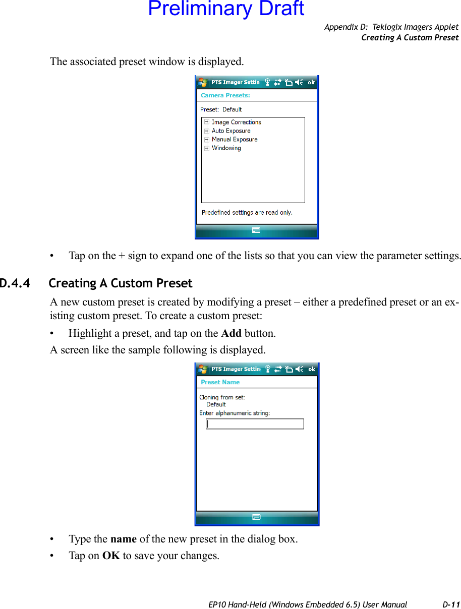
Users Manual


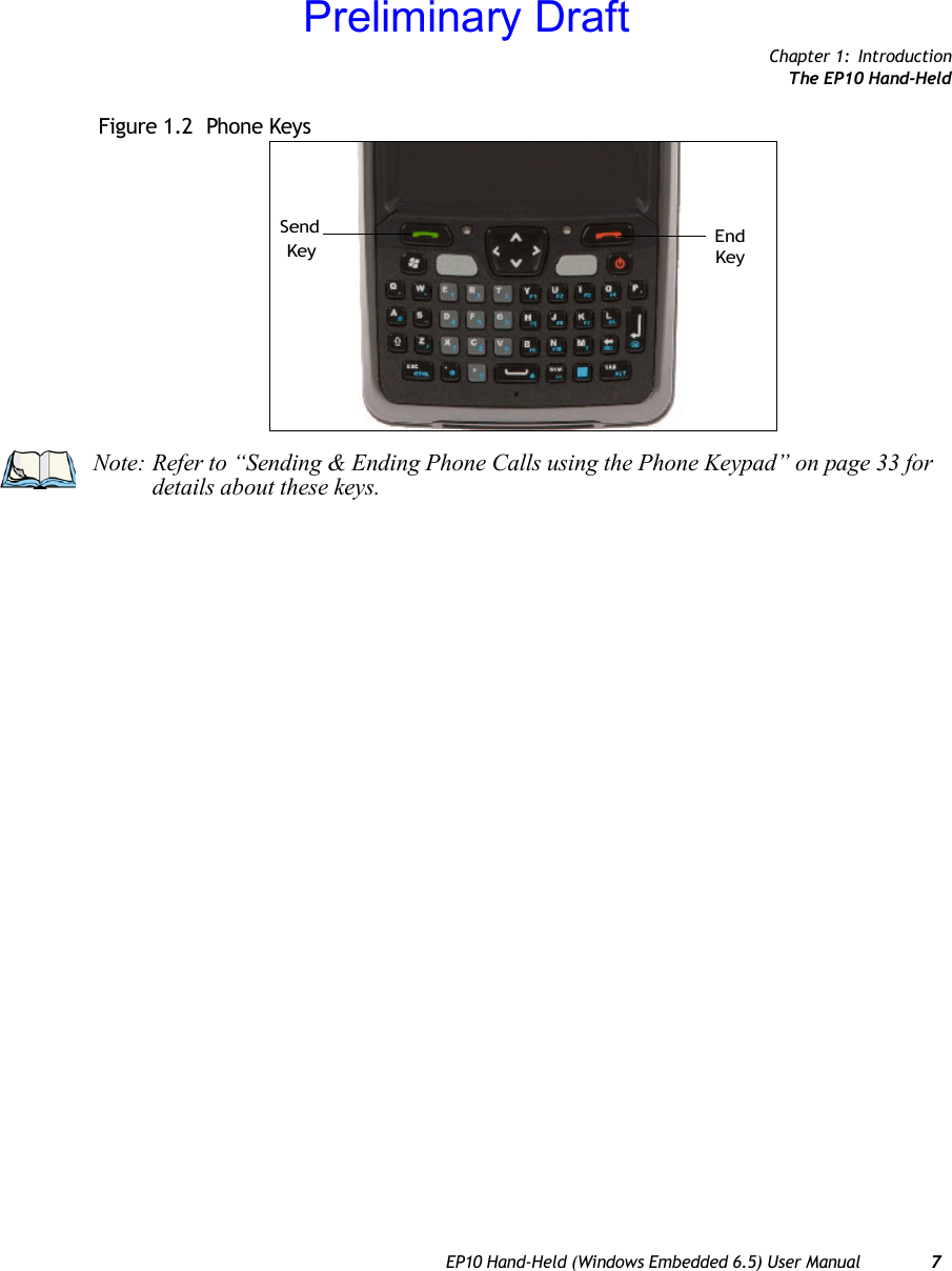

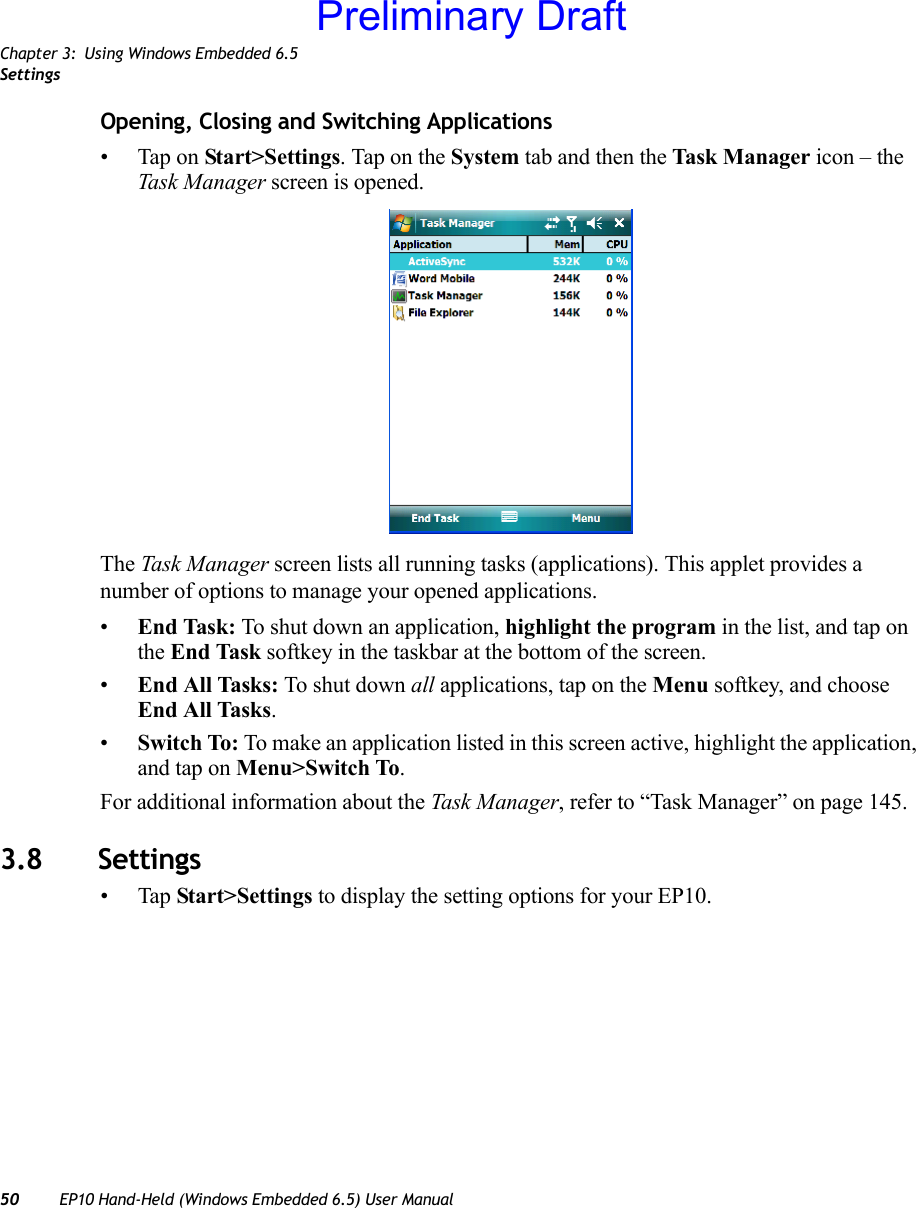
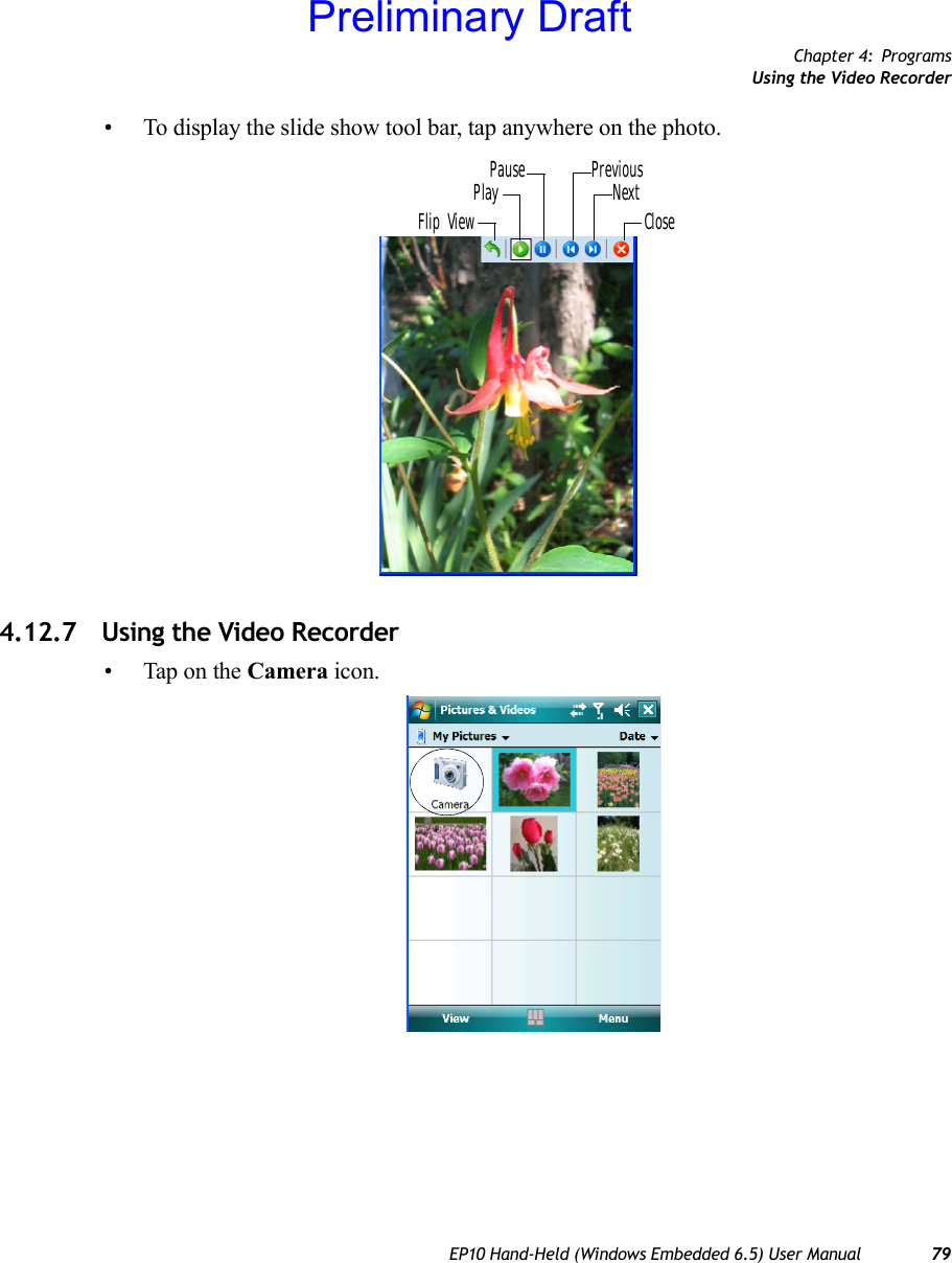
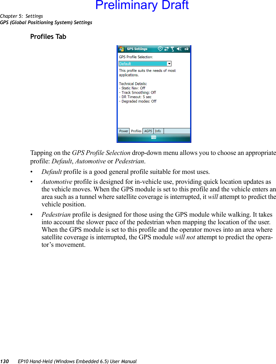
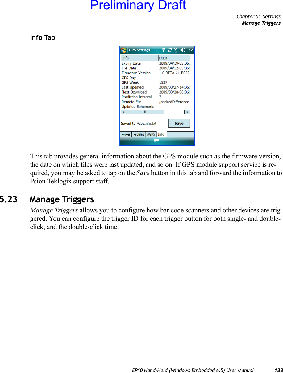
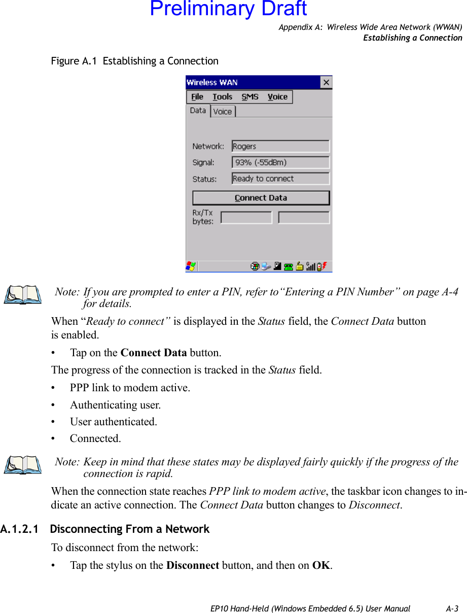
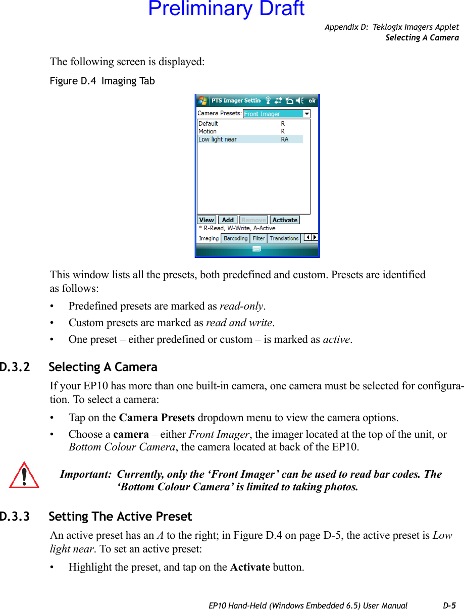
![Chapter 2: Getting to Know the EP10The KeyboardEP10 Hand-Held (Windows Embedded 6.5) User Manual 152.3 The Keyboard2.3.1 EP10 QWERTY KeyboardThe EP10 is available with a QWERTY keyboard with [Send] and [End] phone keys.Figure 2.3 QWERTY Keyboard with Phone KeysMost of the keys on these keyboards operate much like a desktop computer. Where a key or key function is not consistent with the PC keyboard, the differences are noted.The [BLUE] modifier key provide access to additional keys and system functions. These functions are colour coded in blue print above the keyboard keys.Note: Refer to “Monitoring the Battery and Maximizing Run Time” on page 23 for addi-tional information about the battery.Important: To avoid damaging the battery, chargers will not begin the charge process until the battery temperature is between 0°C to 40°C (32°F to 104°F).Preliminary Draft](https://usermanual.wiki/Psion/7515CA.Users-Manual/User-Guide-1515870-Page-29.png)
![Chapter 2: Getting to Know the EP10Locking the Keyboard16 EP10 Hand-Held (Windows Embedded 6.5) User Manual2.3.2 Locking the KeyboardYou can lock the keyboard to prevent accidental key presses. To set up the locking/unlock-ing key sequence:• Tap on Start>Settings>Buttons. Tap on the right arrow icon in the bottom-right corner of the screen to scroll to the Lock Sequence tab.Refer to “Lock Sequence” on page 106 for details about setting up this function.2.3.3 Modifier KeysThe [SHIFT], [CTRL], [ALT], and [BLUE] keys are modifier keys. Pressing a modifier key changes the function of the next key pressed. For example, on a QWERTY keyboard, the ‘@’ symbol is printed in blue on the [A] key. Pressing the [BLUE] key, a modifier key, fol-lowed by the [A] key displays the ‘@’ symbol rather than the letter A.The [SHIFT], [CTRL] and [ALT] keys operate much like a desktop keyboard except that they are not chorded (two keys held down simultaneously). The modifier key must be pressed first followed by the key whose function you want modified.2.3.3.1 Activating Modifier Keys & the Shift-State IndicatorWhen a modifier key is pressed, it is represented in the shift-state indicator icon in the softkey bar at the bottom of the screen, making it easier to determine whether or not a modi-fier key is active. If the shift-state indicator icon is not visible (you can only see the soft keyboard icon), you may need to take a few steps to display the shift-state indicator icon.• Tap on Start>Settings followed by the Buttons icon.• Tap on the One Shots tab at the bottom of the screen.• Tap in the check box next to Show modifier key state to display the shift-state indicator icon.Note: Almost all keys can be reprogrammed to suit your requirements.Note: Keep in mind that the [ALT] and [CTRL] keys are only available on key-pads that are not equipped with phone keys. You can, however, access the [CTRL] key using the onscreen, soft keyboard.Preliminary Draft](https://usermanual.wiki/Psion/7515CA.Users-Manual/User-Guide-1515870-Page-30.png)
![Chapter 2: Getting to Know the EP10The KeysEP10 Hand-Held (Windows Embedded 6.5) User Manual 17Figure 2.4 Shift-State Indicator Icon2.3.3.2 Locking Modifier KeysWhen a modifier key is locked ‘on’, it will remain active until it is pressed again to unlock or turn it off. To help you identify when a modifier key is locked ‘on’, the key is represented in the shift-state indicator icon with a black frame around it. Figure 2.5 Shift-State Indicator Icon – Locked Modifier KeyOnce a modifier key is unlocked or turned off, it is no longer displayed in the shift-state in-dicator icon.2.3.4 The KeysThe [SHIFT] KeyThe [SHIFT] key is used to display uppercase alpha characters and provide access to the symbols above the numeric keys. You can lock this key ‘on’ so that when you press an alpha Soft Keyboard IconShift-State Indicator Icon replaces Soft Keyboard IconNote: The locking behaviour of the modifier keys can be changed so that, for example, pressing a modifier key once will lock the key ‘on’. Refer to “One Shots” on page 99 for details. Note too that by default, the [ORANGE] key is locked ‘on’ when pressed only once.Preliminary Draft](https://usermanual.wiki/Psion/7515CA.Users-Manual/User-Guide-1515870-Page-31.png)
![Chapter 2: Getting to Know the EP10The Keys18 EP10 Hand-Held (Windows Embedded 6.5) User Manualkey, an upper case character is displayed. When you press a numeric key, the associated symbol on the numeric key is displayed on the screen.If you press the [SHIFT] key twice, it is locked ‘on’ essentially acting as a [CAPS] key, dis-playing uppercase characters. In this state, if you type a numeric key, the number rather than the symbol above it is displayed. Press [SHIFT] again to turn the [CAPS] function off.The Arrow KeysThe Arrow keys are located near the top of the keyboard. The arrow keys move the cursor around the screen–up, down, left and right. The cursor is the flashing box or underline char-acter that indicates where the next character you type will appear.The [BKSP/DEL] KeyThe [BKSP] key (sometimes referred to as destructive backspace) moves the cursor one character to the left, erasing the incorrectly entered key stroke. The [DEL] key ([BLUE] [BKSP]) erases the character at the cursor position.The [ALT] and [CTRL] KeysThe [ALT] and [CTRL] keys modify the function of the next key pressed and are application dependent.The [TAB] KeyTypically, the [TAB] key moves the cursor to the next field to the right or downward.The [ESC] KeyGenerally, this key is used as a keyboard shortcut to close the current menu, dialog box or activity and return to the previous one.The [SPACE] KeyPressing this key inserts a blank space between characters. In a Windows dialog box, press-ing the [SPACE] key enables or disables a checkbox.The [SCAN] KeysThe EP10 is equipped with two [SCAN] keys located on the keyboard just below the display along with [SCAN] buttons situated on the left and right sides of the hand-held. [SCAN] keys activate the scanner beam. For units that do not have internal scanners, these keys can be remapped to serve other functions.Preliminary Draft](https://usermanual.wiki/Psion/7515CA.Users-Manual/User-Guide-1515870-Page-32.png)
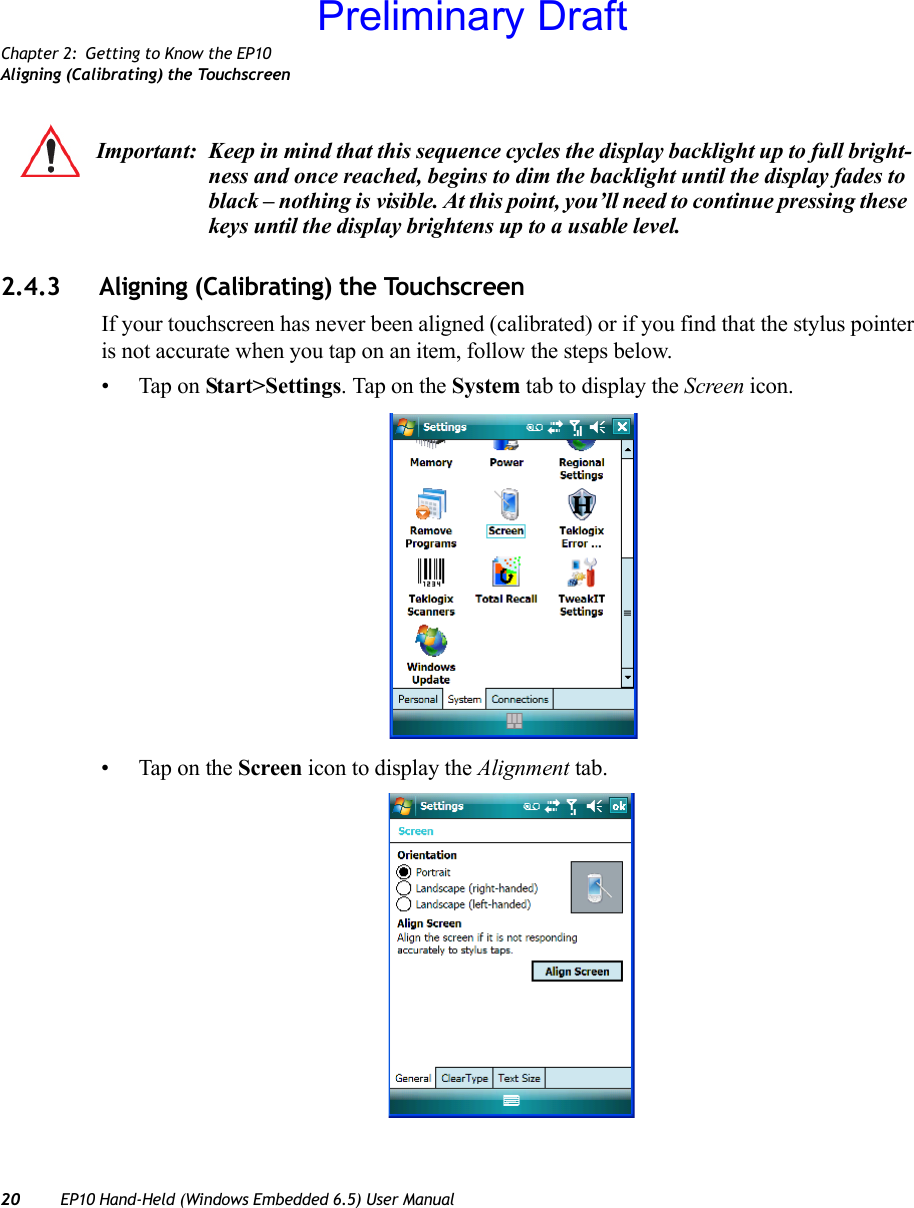
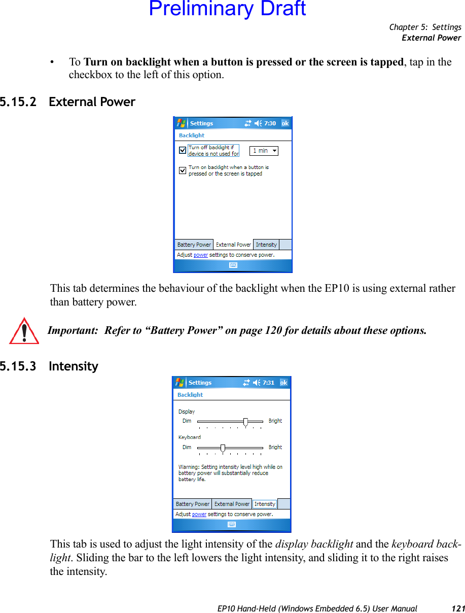
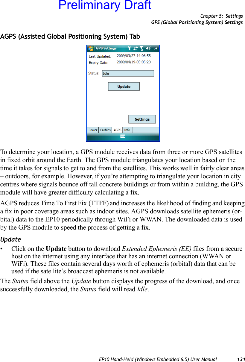
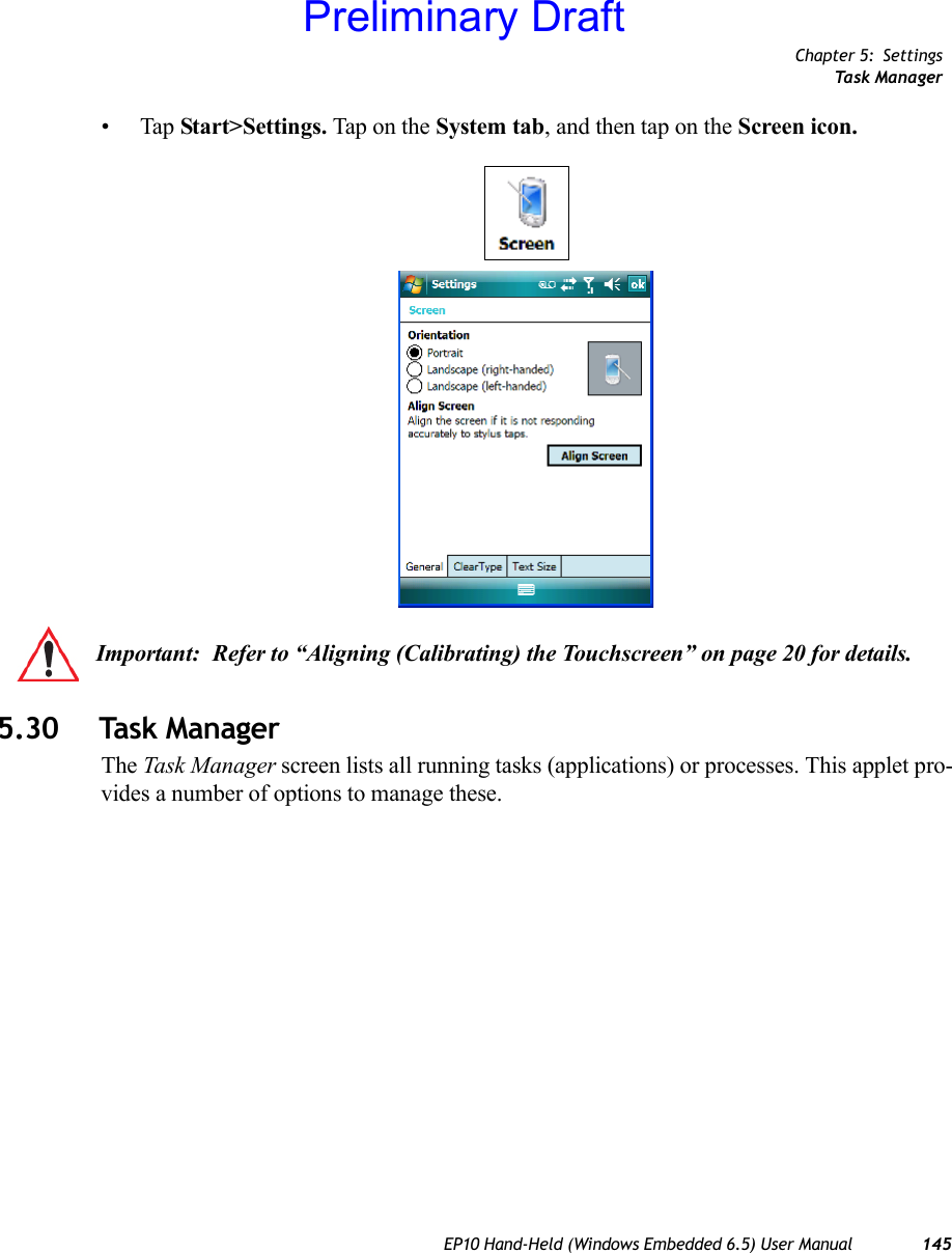
![Chapter 2: Getting to Know the EP10The Keypad BacklightEP10 Hand-Held (Windows Embedded 6.5) User Manual 19The Function Keys–[F1] to [F10]Function keys [F1] to [F10] perform special, custom-defined functions. These keys are ac-cessed by pressing [BLUE] followed by numeric keys [1] to [10]. They can be used with the Windows Mobile 6.5 operating system or another application. The Macro KeysWhile macro keys are not physically stamped on the keyboard, up to 12 macro functions can be added using the Scancode Remapping function. Refer to “Scancode Remapping” on page 103 for details about mapping keys.For details about creating a macro, refer to “Keyboard Macro Keys” on page 101.2.3.5 The Keypad BacklightThe intensity of the keypad backlight can be configured using the Backlight icon accessed by tapping on Start>Settings. Refer to “Backlight” on page 120 for details about this option.2.4 The DisplayEP10s are equipped with display backlighting to improve character visibility in low light conditions. The backlight switches on when a key is pressed or the screen is tapped.2.4.1 Setting the Backlight Intensity & DurationTo set the backlight intensity and the duration of time that the backlight will remain on, you’ll need to choose the Backlight icon. • Tap on Start>Settings and then, tap on System tab>Backlight icon.Refer to “Backlight” on page 120 for details.2.4.2 Adjusting the Backlight using the KeyboardThe display backlight can be adjusted using a keyboard key sequence. The key sequence varies depending on the type of keyboard:•For alphanumeric keyboards, lock the [ORANGE] key ‘on’. Press [ESC] until a satis-factory brightness level is attained.(TBD)Preliminary Draft](https://usermanual.wiki/Psion/7515CA.Users-Manual/User-Guide-1515870-Page-33.png)

![Chapter 3: Using Windows Embedded 6.5The Softkey Bar48 EP10 Hand-Held (Windows Embedded 6.5) User ManualThe Soft Keyboard IconTapping on the soft keyboard icon displays an onscreen keyboard you can use as an alterna-tive to the EP10 keyboard.Shift-State Indicator IconThe softkey bar can also display the shift-state indicator icon. This icon indicates active modifier keys–[SHIFT], [ALT], [CTRL], [ORANGE] and [BLUE]. • Tap on Start>Settings>Buttons>One Shots. Tap in the checkbox next to Show modi-fier key state, to replace the soft keyboard icon with the shift-state indicator icon.When a modifier key is pressed, it is displayed in the shift-state indicator icon. In the example above, the [ORANGE] key was activated.To distinguish a ‘locked’ modifier key – a key that has been locked ‘on’ – from a modifier key that is only active until the next key is pressed, ‘locked’ keys are encircled in a black frame in the shift-state indicator icon. Refer to “Activating Modifier Keys & the Shift-State Indicator” on page 16 for details.Shift-state indicator iconNote: You can still access the soft keyboard while the shift-state indicator icon is displayed. Tapping on this icon displays the soft keyboard. Tapping on the shift-state indicator icon again removes the soft keyboard. Preliminary Draft](https://usermanual.wiki/Psion/7515CA.Users-Manual/User-Guide-1515870-Page-62.png)
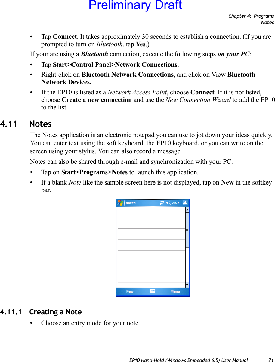
![Chapter 3: Using Windows Embedded 6.5Entering Text52 EP10 Hand-Held (Windows Embedded 6.5) User Manual3.10 Entering TextYou can enter text using either the soft keyboard or the EP10 keyboard. You can also use the Transcriber to handwrite information directly on the touchscreen using your stylus.• Open an existing document or create a new one– tap Start>Office Mobile>Word Mobile and tap on New in the softkey bar to create a new document.If you’re using the EP10 keyboard to enter text, there are no special steps. Just begin typing – the text, spaces, etc. will appear in the document.3.10.1 Soft KeyboardThe soft keyboard is laid out just like the keypad on a PC keyboard. By tapping the stylus on letters and modifier keys like the [SHIFT] key, you can enter text in a document.If the soft keyboard is not already displayed:• Tap on the soft keyboard icon in the softkey bar.• Tap on the keys in the soft keyboard to enter text in your document.To switch to a numeric keyboard:• Tap on the 123 key in the upper-left corner of the soft keyboard.• Tap on this key again to return to the standard keyboard.Note: For additional information about tailoring text entry using the soft keyboard, the transcriber, the block recognizer and the letter recognizer, refer to “Input” on page 107.Soft KeyboardSoft Keyboard IconPreliminary Draft](https://usermanual.wiki/Psion/7515CA.Users-Manual/User-Guide-1515870-Page-66.png)

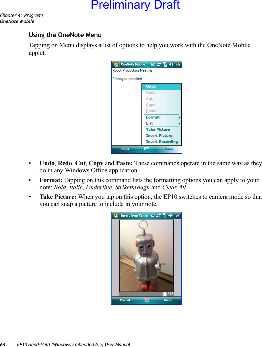
![Chapter 4: ProgramsOneNote MobileEP10 Hand-Held (Windows Embedded 6.5) User Manual 65Press [ENTER/Power] to snap a photo that is automatically inserted into your note.•Insert Picture: Tapping on this command automatically displays your My Pictures folder where you can tap on an existing picture to insert it into your note.Preliminary Draft](https://usermanual.wiki/Psion/7515CA.Users-Manual/User-Guide-1515870-Page-79.png)
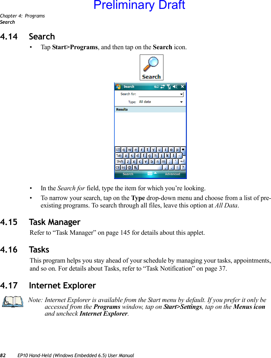
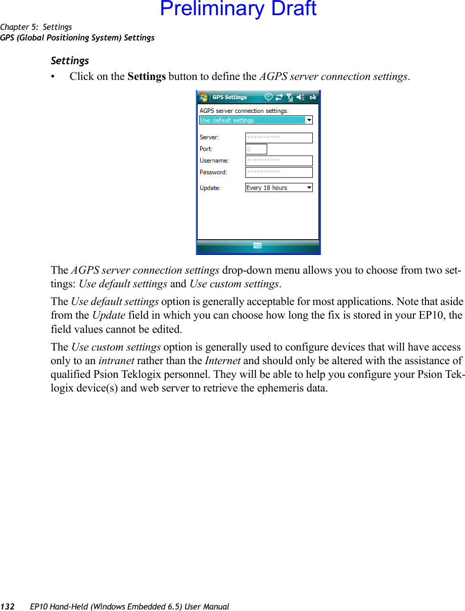
![Chapter 4: ProgramsUsing the Camera76 EP10 Hand-Held (Windows Embedded 6.5) User ManualKeep in mind that if there are no pictures stored on your EP10 as yet, you’ll only see the Camera icon in this screen.• Tap on the Camera icon to activate the camera.The screen will display the image your camera is pointed at. (The camera is built into the back of the EP10.)• Frame the image in the EP10 screen. Press [ENTER/Power] to snap the photograph.Photo MenuWhen the camera is activated, tapping on Menu displays a set of commands to help you modify how your camera operates, the quality of the photos it takes, and so on. You can also use this menu to activate the video recorder rather than the still camera.Photo File IconIndicates the camerais active.Tapping on this softkeydisplays thumbnails ofphotos stored on the EP10.Preliminary Draft](https://usermanual.wiki/Psion/7515CA.Users-Manual/User-Guide-1515870-Page-90.png)
![Chapter 4: ProgramsRemote Desktop Mobile80 EP10 Hand-Held (Windows Embedded 6.5) User Manual• In the bottom-right corner of the camera screen, tap on Menu>Video.• Press [ENTER/Power] to begin recording.• To end the video, press [ENTER/Power] again, or tap on the Stop softkey.4.13 Remote Desktop MobileThis program allows you to log onto a Windows Terminal Server and run the desktop pro-grams from the server on your EP10.Video Recorder IconIndicates that videois active.Note: When the ‘Video’ recorder is activated, a Menu is available to tailor the operation of the recorder, the quality of the recording, and so on.Preliminary Draft](https://usermanual.wiki/Psion/7515CA.Users-Manual/User-Guide-1515870-Page-94.png)


![Chapter 5: SettingsButtons Icon98 EP10 Hand-Held (Windows Embedded 6.5) User Manual5.4 Buttons Icon• Tap on Start>Settings, and then tap on the Buttons icon to display your options.5.4.1 Up/Down ControlSliding the Delay before first repeat bar to the left decreases the delay between key repeats while sliding the bar to the right increases the repeat delay time.Sliding the Repeat rate bar to the left slows the rate at which an [Up/Down] button repeats when pressed. Sliding the bar to the right increases the key repeat rate.Note: The ‘Program Buttons’ option is not available on the EP10.Preliminary Draft](https://usermanual.wiki/Psion/7515CA.Users-Manual/User-Guide-1515870-Page-112.png)
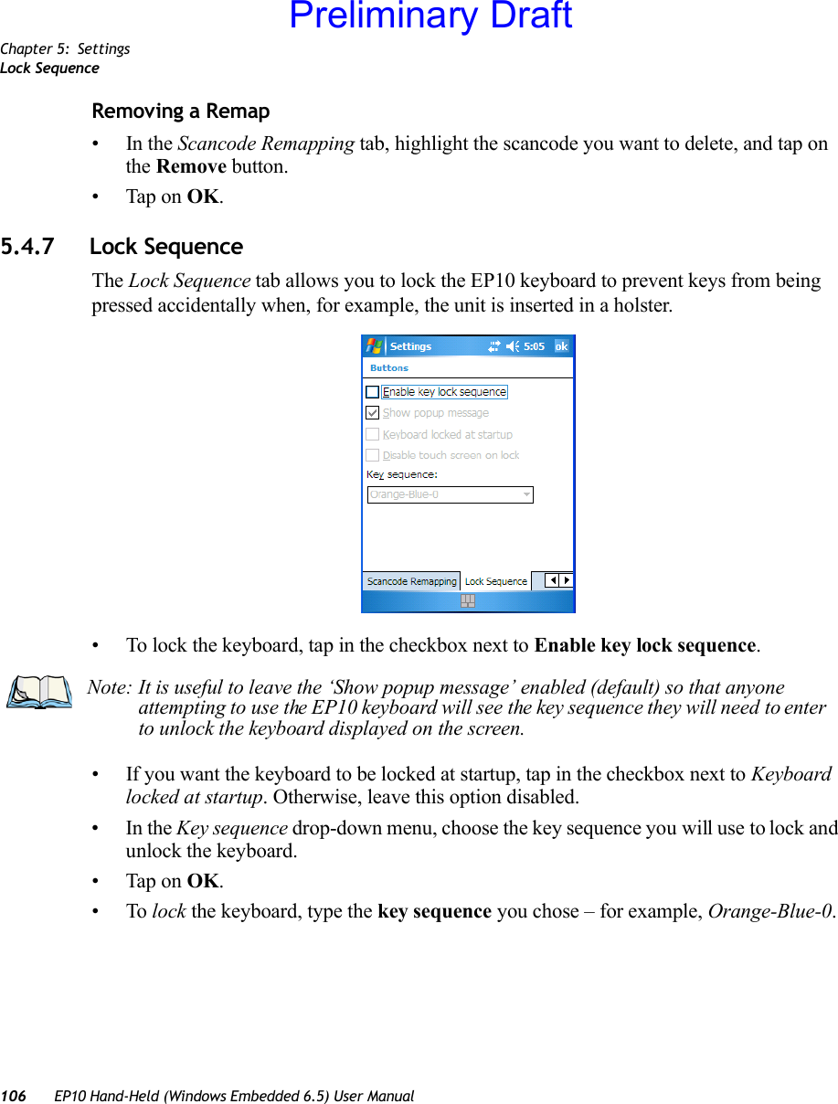
![Chapter 5: SettingsSequenceEP10 Hand-Held (Windows Embedded 6.5) User Manual 995.4.2 Sequence This slider determines the allowable pause between alpha key presses on a keypad. For example, suppose you want to type the letter ‘c’ – you would need to press the [2] key three times. With the [ORANGE] key locked ‘on’, if you press [2] twice and then pause between key presses for 1 second, the letter ‘b’ will be selected automatically. Moving the Sequence slider to the right increases the pause time between alpha key presses.5.4.3 One ShotsThe options in this tab allows you to determine how modifier keys on your EP10 behave. For each modifier key – [ALT], [SHIFT], [CTRL], [ORANGE] and [BLUE] – you have the following options in the drop-down menu: Lock, OneShot, and OneShot/Lock.Preliminary Draft](https://usermanual.wiki/Psion/7515CA.Users-Manual/User-Guide-1515870-Page-113.png)
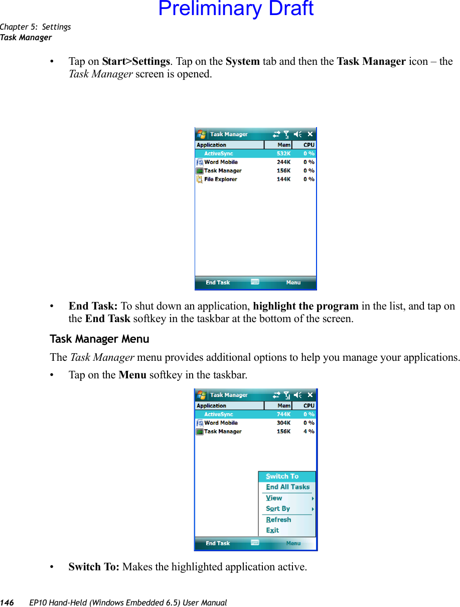
![Chapter 5: SettingsKeyboard Macro KeysEP10 Hand-Held (Windows Embedded 6.5) User Manual 1015.4.4 Keyboard Macro KeysMacro keys are not labelled on the keypad. However, you can map up to 12 macro functions using the keyboard remapping function described in “Scancode Remapping” on page 103. A macro has 20 programmable characters (or “positions”). The macro keys can be pro-grammed to replace frequently used keystrokes, along with the function of executable keys including [ENTER/Power] and [BKSP], function keys, and arrow keys.Recording and Saving a Macro•In the Macro menu, highlight a macro key number–for example, macro 1 to assign a macro to macro key [M1]. Tap on the Record button. A Record Macro screen is displayed.• Type the macro sequence you want to assign to the Macro key. You can type text and numbers, and you can program the function of special keys into a macro.Preliminary Draft](https://usermanual.wiki/Psion/7515CA.Users-Manual/User-Guide-1515870-Page-115.png)
![Chapter 5: SettingsUnicode Mapping102 EP10 Hand-Held (Windows Embedded 6.5) User Manual• When you’ve finished recording your macro sequence, tap on Stop Recording. A new screen – Verify Macro – displays the macro sequence you created. • Tap on the Save button to save your macro. Your macro key sequence is listed in the Macro screen. • Tap on OK to save your macro key assignment.Executing a Macro• Press the macro key to which you’ve assigned the macro to execute it.Deleting a Macro•In the Macros tab, highlight the macro number you want to delete.• Tap on the Delete button.5.4.5 Unicode Mapping• Tap on the Unicode Mapping tab to display this screen.The Unicode Mapping tab is used to map combinations of virtual key values and [CTRL] and [SHIFT] states to Unicode™ values. This tab shows the configured Unicode character along with the Unicode value. For example, “a (U+0061)” indicates that the character “a” is represented by the Unicode value “0061”, and so on. Keep in mind that Unicode configura-tions are represented as hexidecimal rather than decimal values.All user-defined Unicode mappings are listed in the Unicode Mapping tab in order of virtual key value, and then by order of the shift state. If a Unicode mapping is not listed, the Unicode mapping is mapped to the default Unicode value.Preliminary Draft](https://usermanual.wiki/Psion/7515CA.Users-Manual/User-Guide-1515870-Page-116.png)
![Chapter 5: SettingsScancode RemappingEP10 Hand-Held (Windows Embedded 6.5) User Manual 103Adding and Changing Unicode Values• Tap on the Add/Change button.• Highlight a value in the Unicode mapping list.• Position the cursor in the Unicode Mapping field, and type a Unicode value for the highlighted key.Removing Unicode Values•In the Unicode Mapping tab, highlight the item you want to delete, and tap the Remove button.5.4.6 Scancode RemappingA scancode is a number that is associated with a physical key on a keyboard. Every key has a unique scancode that is mapped to a virtual key, a function or a macro. Scancode Remap-ping allows you to change the functionality of any key on the keyboard. A key can be remapped to send a virtual key (e.g. VK_F represents the ‘F’ key; VK_RETURN represents the [ENTER/Power] key, etc.), perform a function (e.g. turn the scanner on, change vol-ume/contrast, etc.) or run a macro.Important: Changes to Unicode mappings are not saved until you exit the Unicode Mapping tab by tapping on [OK].Note: To add a shifted state – [SHIFT] and/or [CTRL], tap on the checkbox next to ‘SHIFT Pressed’ and/or ‘CTRL Pressed’.Preliminary Draft](https://usermanual.wiki/Psion/7515CA.Users-Manual/User-Guide-1515870-Page-117.png)
![Chapter 5: SettingsScancode Remapping104 EP10 Hand-Held (Windows Embedded 6.5) User ManualThere are three different tables of scancode mappings: the Normal table, the Blue table and the Orange table. The Normal table defines unmodified key presses; the Blue table defines key presses that occur when the [BLUE] modifier is on; the Orange table defines key presses that occur when the [ORANGE] modifier is on. The default mappings of these scan-codes can be overwritten for each of these three tables using the Scancode Remapping tab.The first column in the Scancode Remapping tab displays the Scancodes in hexidecimal. If the scancode is remapped to a virtual key, that virtual key is displayed in the next column labelled ‘V-Key’. A virtual key that is ‘Shifted’ or ‘Unshifted’ is displayed in the third column labelled ‘Function’. If the scancode is remapped to a function or a macro, the first and second columns remain blank while the third column contains the function name or macro key number (e.g., Macro 2).Adding a RemapTo add a new remapping:• Tap the Add button at the bottom of the dialog box.Preliminary Draft](https://usermanual.wiki/Psion/7515CA.Users-Manual/User-Guide-1515870-Page-118.png)
![Chapter 5: SettingsScancode RemappingEP10 Hand-Held (Windows Embedded 6.5) User Manual 105The Remap Scancode dialog box is displayed.• Type the scan code in hexidecimal in the field labelled Scancode.Virtual Key, Function and MacroThe radio buttons at the bottom of the dialog box allow you to define to what the scan code will be remapped to: Virtual Key, Function or Macro. When Virtual Key is selected, you can choose to force [SHIFT] to be on or off when the virtual key is sent. If No Force is selected, the shift state is dependent on whether the shift state is on or off at the time the virtual key is sent.When Function is selected, a list of valid functions appears in the dialog box. When Macro is selected, the macro keys available on your unit are listed in the dialog box.• Choose Virtual Key>Function or Macro.• Choose a function from the Function list, and tap on OK.Editing a Scancode Remap•In the Scancode Remapping tab, tap on the remap you want to edit.• Tap on the Edit button, and make the appropriate changes.• Tap on OK to save your changes.Note: The ‘Label’ field displays the default function of the scancode you are remapping.Preliminary Draft](https://usermanual.wiki/Psion/7515CA.Users-Manual/User-Guide-1515870-Page-119.png)
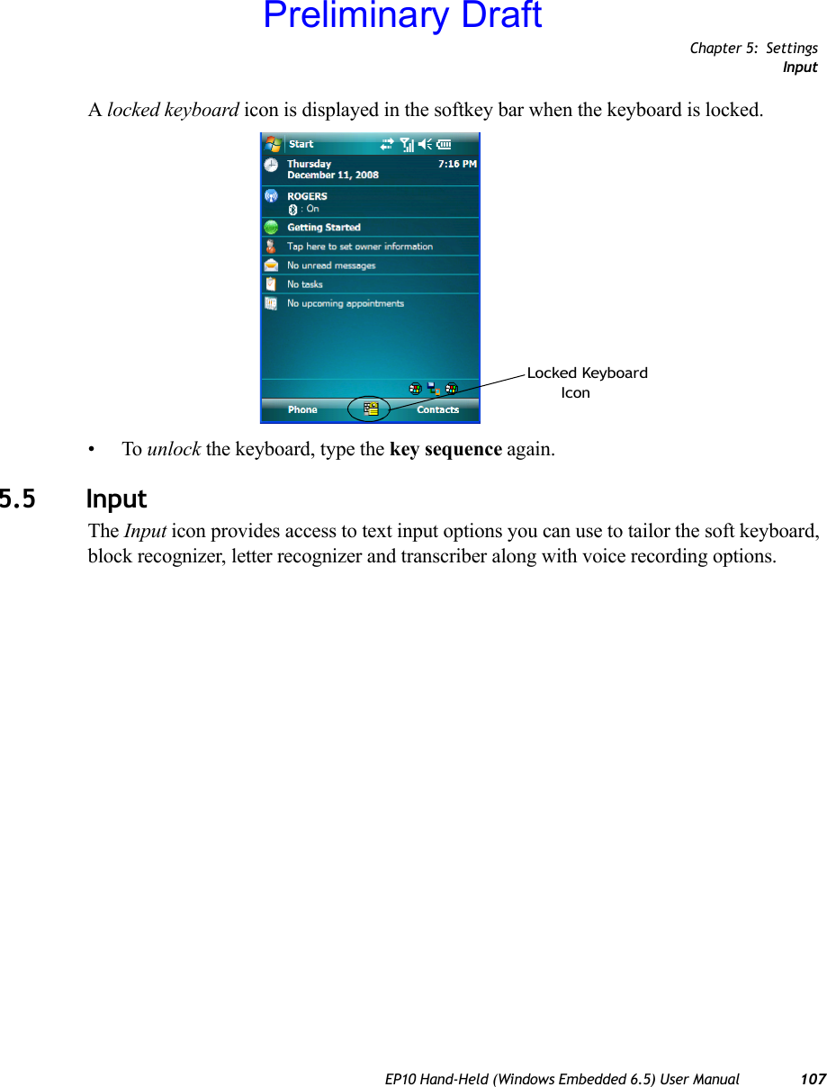
![Chapter 5: SettingsTrigger Mappings134 EP10 Hand-Held (Windows Embedded 6.5) User Manual• Tap on Start>Settings>System tab>Manage Triggers icon.5.23.1 Trigger MappingsA trigger mapping is an association between a particular key on the keyboard and a driver or application, the module(s) – sometimes referred to as “trigger consumer(s)” – of the trigger source. Along with keyboard keys, trigger sources can also be grip triggers, external hard-ware triggers or software-based. When the specified key is pressed, the trigger consumer (for example, a decoded scanner) is sent a message.Double-ClickWhen a key is pressed and released, then pressed again within the configured time (between 0 to 1000 milliseconds), a double-click occurs. See also “Trigger Press Type” on page 136.Important: It is not possible to have two or more identical mappings — for example [F1] cannot be mapped to the Non-Decoded Scanner twice — even if the trigger type is different.A keyboard key that is used as a trigger source will no longer generate key data or perform its normal function. For example, if the space button is used as a trigger source, it will not be able to send space characters to applications.Preliminary Draft](https://usermanual.wiki/Psion/7515CA.Users-Manual/User-Guide-1515870-Page-148.png)
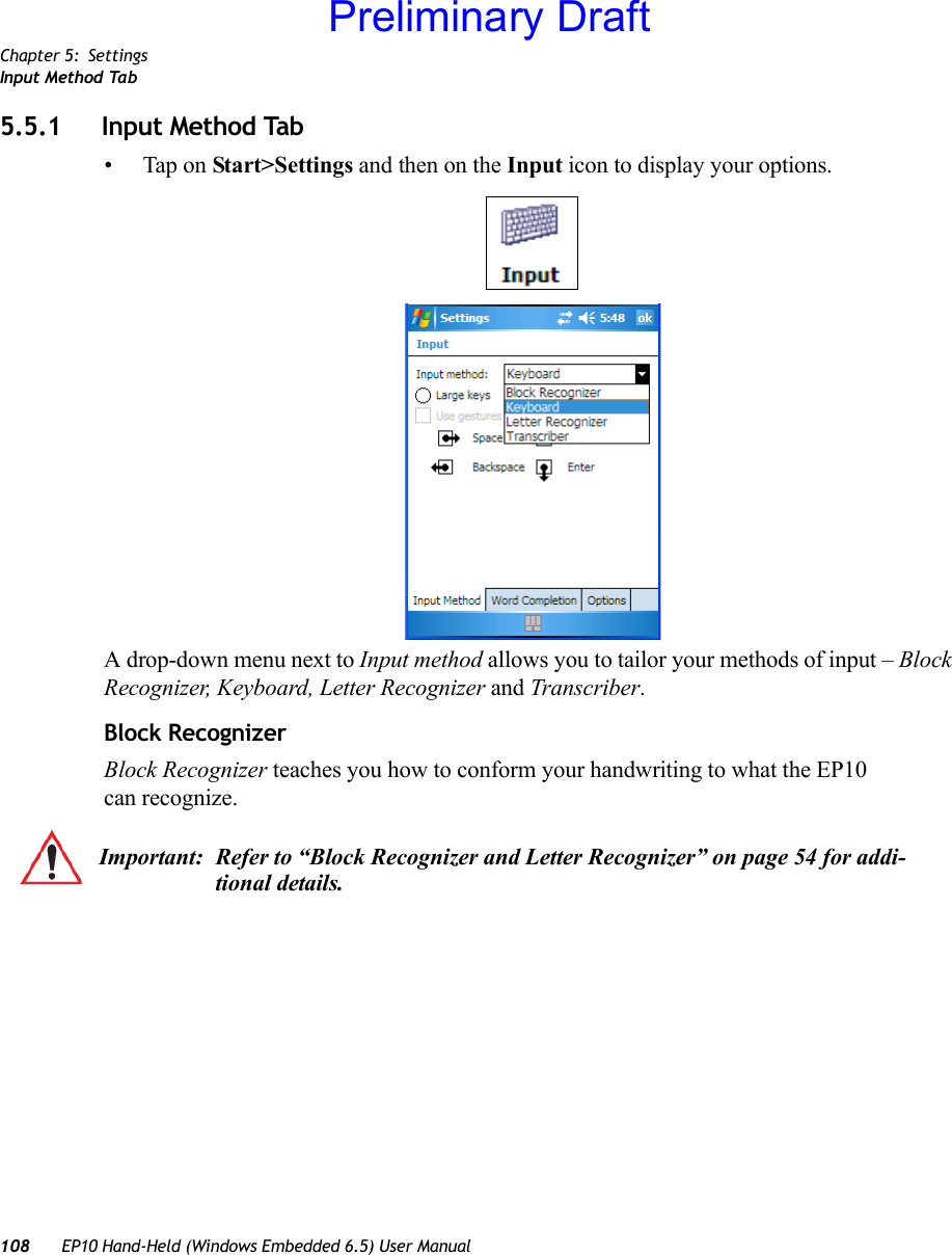
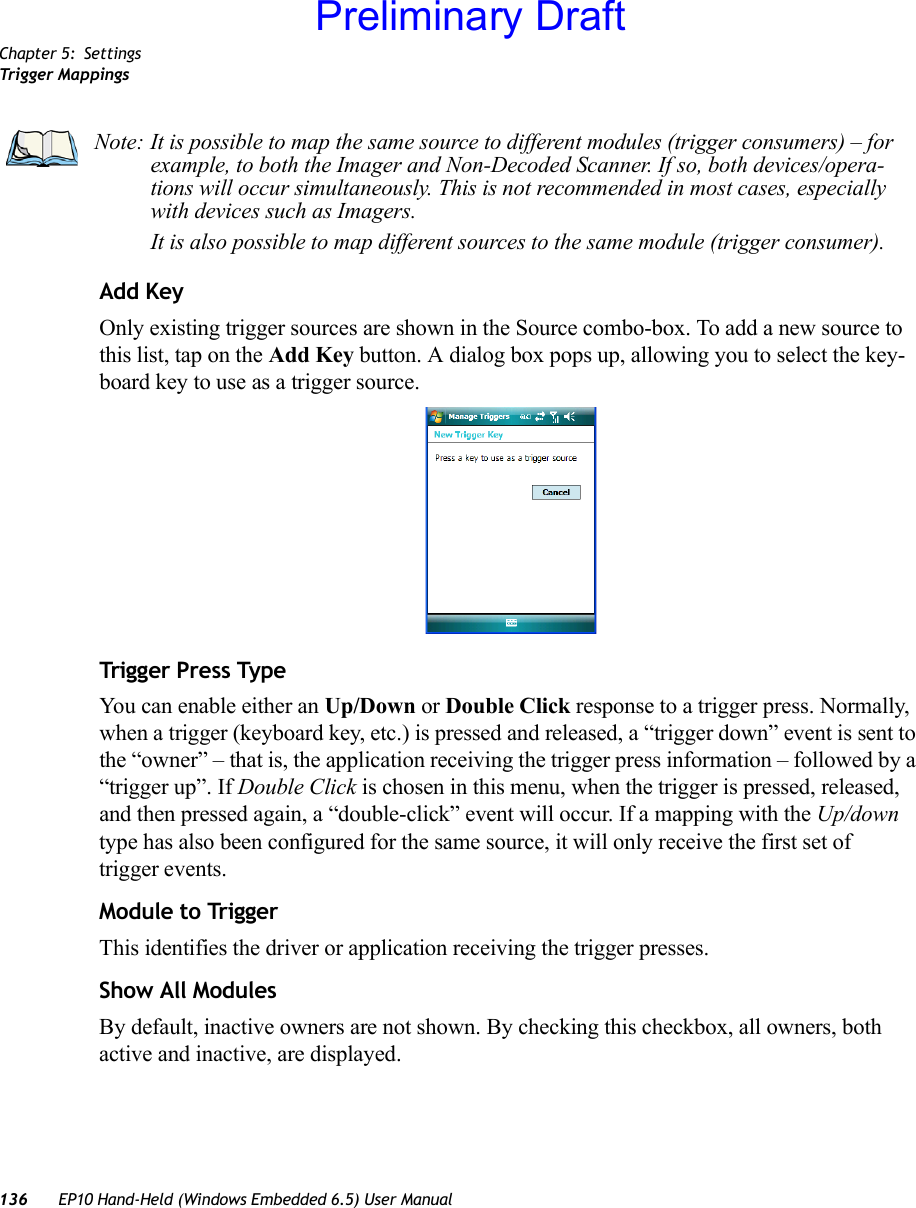
![Chapter 5: SettingsTrigger MappingsEP10 Hand-Held (Windows Embedded 6.5) User Manual 135Show All ModulesBy default, the trigger mapping list only shows active mappings. Mappings for drivers or applications that are not currently active are not normally displayed. By checking this checkbox, all mappings, both active and inactive, are displayed.AddTapping this button brings up the Add mapping dialog (see below), so that you can add new trigger mappings.EditTapping this button brings up the Edit mapping dialog, so that you can edit existing trigger mappings.RemoveTapping this button removes an existing mapping.OKThe OK button in the top right of the Manage Triggers screen saves all changes made. If the [ESC] key is pressed, all changes are discarded.5.23.1.1 Add and Edit Trigger Mapping• Tap on Add to add a new trigger map, or tap on Edit to edit an existing trigger map.Trigg er KeyThis drop-down list allows you to specify the source of the trigger events, such as the Grip Trigger, Left Scan, etc., for the trigger module selected.Preliminary Draft](https://usermanual.wiki/Psion/7515CA.Users-Manual/User-Guide-1515870-Page-149.png)
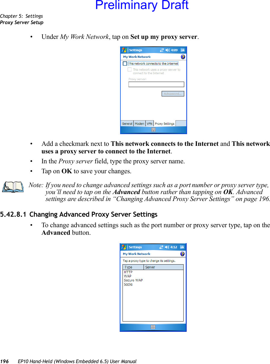
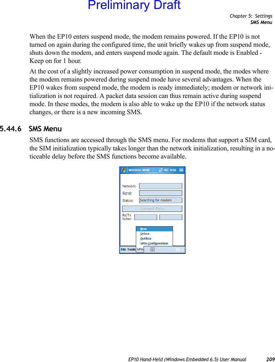
![Chapter 5: SettingsDisconnecting from a NetworkEP10 Hand-Held (Windows Embedded 6.5) User Manual 199• Authenticating user• User authenticated• ConnectedWhen the connection state reaches PPP link to modem active, the softkey bar icon changes to indicate an active connection. The Connect Data button changes, displaying Disconnect.5.44.3 Disconnecting from a NetworkTo disconnect from the network:• Tap on the Disconnect button, and then on OK.When the EP10 network connection is severed, the Status field displays Ready to Connect.A unit equipped with a GSM/GPRS expansion board displays the signal strength in the main Wireless WAN screen, even while a connection is active. Units equipped with certain other modems (e.g. Sierra Wireless UMTS and CDMA modems, Novatel UMTS modems) do not display the signal strength while a connection is active.The Rx bytes and Tx bytes fields esti-mate the amount of data transmitted and received, respectively.5.44.3.1 Shutting Down the Wireless WAN User InterfaceWhile it is not usual to shut down the GSM/GPRS user interface, you can accomplish this by tapping on the File menu and choosing the Exit command in the Wireless WAN screen.5.44.4 Advanced InformationIn most cases, when a GSM/GPRS radio and SIM are installed in your EP10, setup is auto-matic. Follow the steps outlined under the heading “Establishing a Connection” on page 198 to make a connection. The information in this section is for advanced setup purposes.5.44.4.1 Entering a PINIf a PIN is required, a PIN entry dialog box is displayed.• Type your PIN, and press [ENTER/Power].Note: Keep in mind that these states may be displayed fairly quickly if the progress of the connection is rapid. Note: Once you’ve shut down the user interface, you can only enable the radio by tapping on the Wireless WAN icon to display the dialog box.Preliminary Draft](https://usermanual.wiki/Psion/7515CA.Users-Manual/User-Guide-1515870-Page-213.png)


![Chapter 7: SpecificationsCinterion PH8 GSM/GPRS/EDGE RadioEP10 Hand-Held (Windows Embedded 6.5) User Manual 2637.2.4 Cinterion PH8 GSM/GPRS/EDGE RadioFeature SpecificationsGeneralFrequency bands GSM/GPRS/EDGE: Quad band, 850/900/1800/1900MHzUMTS/HSPA+: Five band, 800/850/AWS/1900/2100MHzGSM class Small MSOutput power (according to Release 99)Class 4 (+33dBm ±2dB) for EGSM850Class 4 (+33dBm ±2dB) for EGSM900Class 1 (+30dBm ±2dB) for GSM1800Class 1 (+30dBm ±2dB) for GSM1900Class E2 (+27dBm ± 3dB) for GSM 850 8-PSKClass E2 (+27dBm ± 3dB) for GSM 900 8-PSKClass E2 (+26dBm +3 /-4dB) for GSM 1800 8-PSKClass E2 (+26dBm +3 /-4dB) for GSM 1900 8-PSKClass 3 (+24dBm +1/-3dB) for UMTS 2100, WCDMA FDD Bd IClass 3 (+24dBm +1/-3dB) for UMTS 1900,WCDMA FDD Bd IIClass 3 (+24dBm +1/-3dB) for UMTS AWS, WCDMA FDD Bd IVClass 3 (+24dBm +1/-3dB) for UMTS 850, WCDMA FDD Bd VClass 3 (+24dBm +1/-3dB) for UMTS 800, WCDMA FDD Bd VIOperating Temperature (board temperature)Normal operation: -30°C to +85°CRestricted operation: -40°C to +95°CPhysical Dimensions: 33.9mm x 50mm x 3.1mmWeight: approx. 9.5gRoHS All hardware components fully compliant with EU RoHS DirectiveHSPA features3GPP Release 6, 7 DL 14.4Mbps, UL 5.7MbpsUE CAT. [1-6], 11, 12 supportedCompressed mode (CM) supported according to 3GPP TS25.212UMTS features3GPP Release 4 PS data rate - 384 kbps DL / 384 kbps ULCS data rate - 64 kbps DL / 64 kbps ULGSM/GPRS/EGPRS featuresPreliminary Draft](https://usermanual.wiki/Psion/7515CA.Users-Manual/User-Guide-1515870-Page-277.png)

![A-4 EP10 Hand-Held (Windows Embedded 6.5) User ManualAppendix A: Wireless Wide Area Network (WWAN)Advanced InformationWhen the computer’s network connection is severed, the Status field displays “Ready to connect”.The signal strength is displayed in the main Wireless WAN screen, even while a connection is active. The Rx bytes and Tx bytes fields estimate the amount of data transmitted and received, respectively.A.1.2.2 Shutting Down the Wireless WAN User InterfaceWhile it is not usual to shut down the GSM/GPRS user interface, you can accomplish this by tapping on the File menu and choosing the Exit command at the bottom of the main Wireless WAN dialog box.A.1.3 Advanced InformationIn most cases, when a GSM/GPRS radio and SIM are installed in your computer, setup is automatic. Follow the steps outlined under the heading “Establishing a Connection” on page A-2 to make a connection. The information in this section is for advanced setup purposes.A.1.3.1 Entering a PIN NumberIf a PIN is required, a PIN entry dialog box is displayed.• Type your PIN, and press [ENTER].Once the correct PIN or PUK is entered or if none was required, the modem is instructed to perform a GSM network registration followed by a GPRS attach. The main Wireless WAN dialog box reflects the progress of the initialization.• Searching for modem.• Initializing modem.• SIM is ready.• Searching for network.• Registered on network.• Searching for GPRS.Note: Once you’ve shut down the user interface, you can only enable the radio by opening the Control Panel and tapping on the Wireless WAN icon to display the Wireless WAN dialog box.Note: If you exceed the number of allowable attempts, a PUK entry window is brought to the foreground. You’ll need to enter a new PIN number.Preliminary Draft](https://usermanual.wiki/Psion/7515CA.Users-Manual/User-Guide-1515870-Page-286.png)

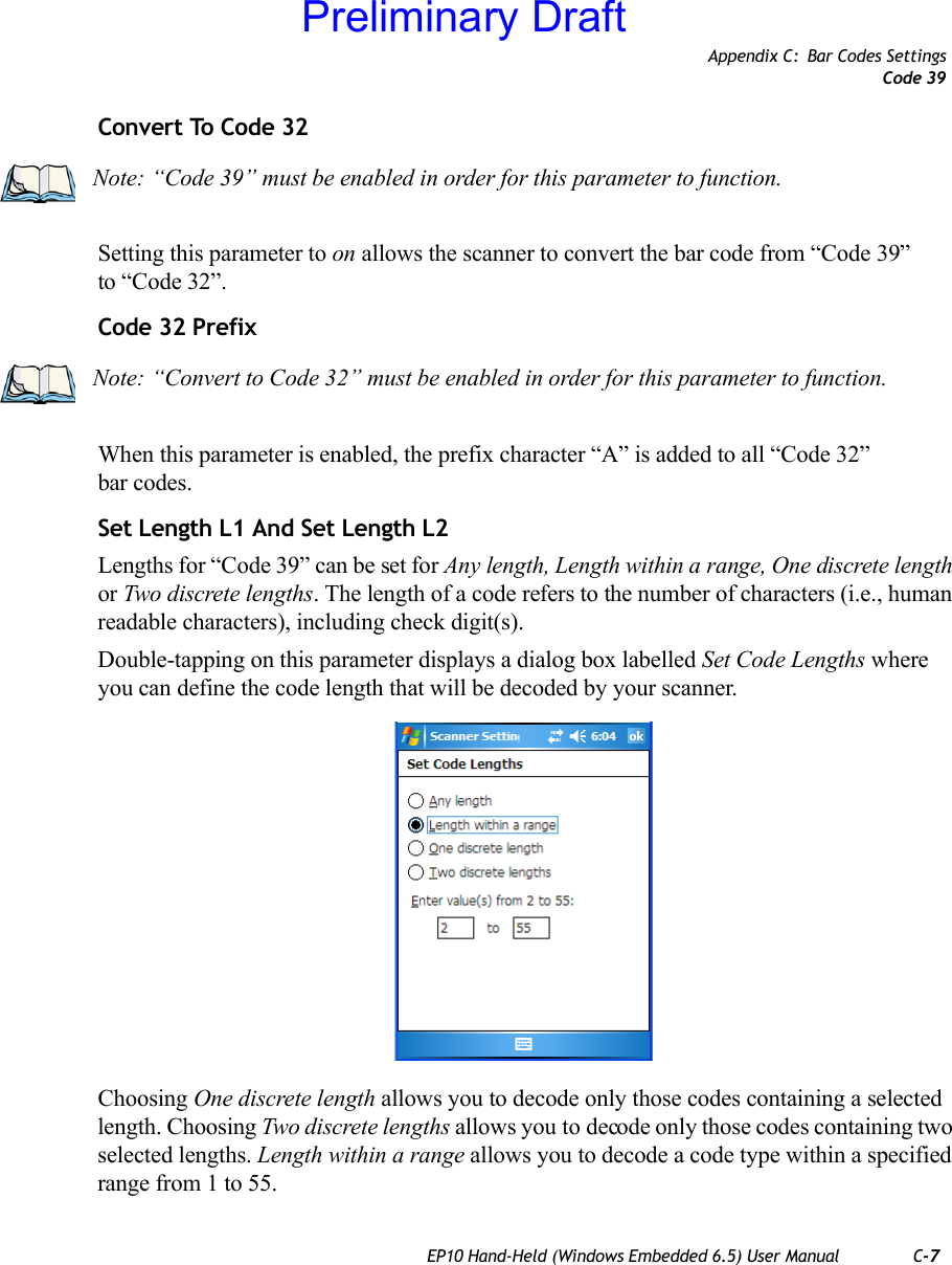
![C-6 EP10 Hand-Held (Windows Embedded 6.5) User ManualAppendix C: Bar Codes SettingsCode 39Scan Data FormatThis parameter allows you to change the scan data transmission format. Double-tapping on “Scan Data Format” displays the following options from which you can choose a data format: data (as-is), data [S1], data [S2], data [S1][S2], [P] data, [P] data [S1], [P] data [S2] and [P] data [S1][S2].Prefix [P], Suffix [S1] And Suffix [S2]A prefix and/or one or two suffixes may be appended to scan data for use in data editing.When you double-tap on these parameters, a dialog box is displayed in which you can enter a value from 0 to 255.Delete Char Set ECIsSetting this parameter to on enables the scanner to delete any escape sequences representing Character Set ECIs – Extended Channel Interpretations (also known as GLIs) from its buffer before transmission. When this parameter is enabled, the scanner transmits data from PDF417 and MicroPDF417 bar codes containing Character Set ECIs, even when the ECI Protocol is disabled.ECI DecoderSetting this parameter to on enables the scanner to interpret any Extended Channel Interpre-tations (ECIs) supported by the scanner. This parameter has no effect on symbols that were not encoded using ECIs. If this parameter is set to off and a symbol that was encoded using an ECI escape is scanned, the scanner transmits the ECI escape followed by the uninterpreted data.C.2.5 Code 39EnabledSetting this parameter to on enables “Code 39”.Enable Trioptic Code 39Trioptic Code 39 symbols always contain six characters. Setting this parameter to on allows this type of symbology to be recognized.Note: “Trioptic Code 39” and “Full ASCII” should not be enabled simultaneously. The scanner does not automatically discriminate between these two symbologies.Preliminary Draft](https://usermanual.wiki/Psion/7515CA.Users-Manual/User-Guide-1515870-Page-308.png)
![Appendix C: Bar Codes SettingsMicro PDF-417EP10 Hand-Held (Windows Embedded 6.5) User Manual C-19C.2.20 Micro PDF-417EnableSetting this parameter to on enables “Micro PDF-417” bar code scanning. Micro PDF-417 is a multi-row symbology that is useful for applications requiring greater area efficiency but lower data capacity than PDF-417.Code 128 EmulationWhen this parameter is enabled, the scanner transmits data from certain Micro PDF-417 symbols as if it was encoded in Code 128 symbols. If Code 128 Emulation is enabled, the following Micro PDF-417 symbols are transmitted with one of the following prefixes:]C1 - if the first codeword is 903-907, 912, 914, 915]C2 - if the first codeword is 908 or 909]C0 - if the first codeword is 910 or 911If Code 128 Emulation is set to off, the Micro PDF-417 symbols are transmitted with one of the following prefixes:]L3 - if the first codeword is 903-907, 912, 914, 915]L4 - if the first codeword is 908 or 909]L5 - if the first codeword is 910 or 911Length RestrictionRefer to “Length Restriction” on page C-8 for details.Add/Remove DataRefer to “Add/Remove Data” on page C-9 for details.Preliminary Draft](https://usermanual.wiki/Psion/7515CA.Users-Manual/User-Guide-1515870-Page-321.png)

![Appendix C: Bar Codes SettingsCode 128EP10 Hand-Held (Windows Embedded 6.5) User Manual C-23Add/Remove DataRefer to “Add/Remove Data” on page C-9 for details.C.3.4 Code 128EnableSetting this parameter to on enables “Code 128”.GS1-128“GS1-128” is the GS1 implementation of the Code 128 barcode specification. The former correct name was UCC/EAN-128.GS1-128 Identifier“GS1-128 Identifier” allows the AIM ID " ]C1" for EAN 128 to be transmitted or removed. By default, this identifier is transmitted if EAN 128 is enabled.GTIN CompliantGTIN (global trade item number) processing transmits EAN 128 as the 14-character EAN/UCC GTIN. To use GTIN processing, you must activate the EAN 128 symbology.FNC1 Conversion“FNC1 Conversion” allows the embedded FNC1 character to be converted to another char-acter for applications that cannot use the default <GS> Group Separator or hex (1d). Double-tapping on this option displays a dialog box listing the allowable range – 0 to 255. Enable ISBT 128 To successfully scan this type of bar code (International Society of Blood Transfusion), this option must be set to on. If you enable this type of bar code, Code 128/EAN 128 is deacti-vated to avoid any confusion.ISBT Concat TransmitThe codes are not concatenated by default. You need to choose one of the options provided for this parameter to send concatenated code. Choosing Only Concatenated Codes transmits only concatenated codes – single codes will not be transmitted. Choosing Concatenated or Important: When EAN 128 and GTIN processing are both activated, it is not possible to read normal EAN 128 Codes. Preliminary Draft](https://usermanual.wiki/Psion/7515CA.Users-Manual/User-Guide-1515870-Page-325.png)
![Appendix C: Bar Codes SettingsPDF-417EP10 Hand-Held (Windows Embedded 6.5) User Manual C-35Security LevelThis parameter is used to differentiate between TLC-39 and standard Code 39. Tapping on “Security Level” displays a dialog box in which you can assign a value from 0 to 100. The higher the value assigned, the lower the decode rate.Length RestrictionRefer to “Length Restriction” on page C-8 for details.Add/Remove DataRefer to “Add/Remove Data” on page C-9 for details.C.3.21 PDF-417EnabledSet this parameter to on to enable “PDF-417”.Length RestrictionRefer to “Length Restriction” on page C-8 for details.Add/Remove DataRefer to “Add/Remove Data” on page C-9 for details.C.3.22 Micro PDF-417EnabledSet this parameter to on to enable “Micro PDF-417”.Code 128 EmulationWhen this parameter is enabled, the scanner transmits data from certain Micro PDF-417 symbols as if it was encoded in Code 128 symbols. If Code 128 Emulation is enabled, the following Micro PDF-417 symbols are transmitted with one of the following prefixes:]C1 - if the first codeword is 903-907, 912, 914, 915]C2 - if the first codeword is 908 or 909]C0 - if the first codeword is 910 or 911If Code 128 Emulation is set to off, the Micro PDF-417 symbols are transmitted with one of the following prefixes:Preliminary Draft](https://usermanual.wiki/Psion/7515CA.Users-Manual/User-Guide-1515870-Page-337.png)
![C-36 EP10 Hand-Held (Windows Embedded 6.5) User ManualAppendix C: Bar Codes SettingsCodablock]L3 - if the first codeword is 903-907, 912, 914, 915]L4 - if the first codeword is 908 or 909]L5 - if the first codeword is 910 or 911Length RestrictionRefer to “Length Restriction” on page C-8 for details.Add/Remove DataRefer to “Add/Remove Data” on page C-9 for details.C.3.23 CodablockEnable Codablock ASet this parameter to on to enable “Codablock type A”.Enable Codablock FSet this parameter to on to enable “Codablock type F”.Length RestrictionRefer to “Length Restriction” on page C-8 for details.Add/Remove DataRefer to “Add/Remove Data” on page C-9 for details.Preliminary Draft](https://usermanual.wiki/Psion/7515CA.Users-Manual/User-Guide-1515870-Page-338.png)
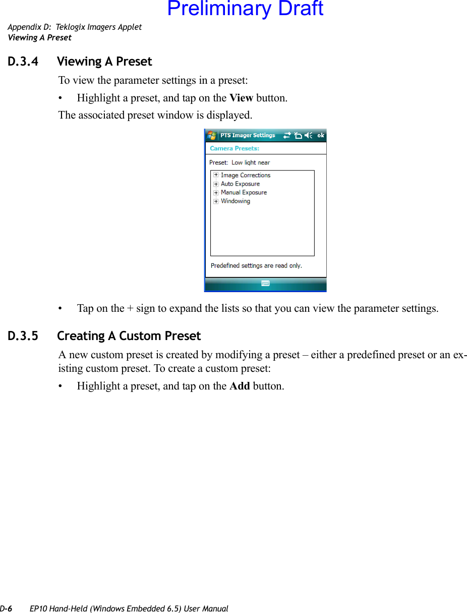
![D-8 EP10 Hand-Held (Windows Embedded 6.5) User ManualAppendix D: Teklogix Imagers AppletModifying A Custom Preset• Highlight the custom preset, and tap on the Edit button.• Tap on the + symbols to expand the lists so that you can view the parameter settings.• Scroll through the parameter list until you reach the parameter that you want to change.• For a parameter that can take a range of values:- Highlight the parameter, and then press the [SPACE] key or double-click the parameter.- An associated dialog box containing the valid range of values for the parameter and the current setting like the sample screen following is displayed.- Type a value in the field provided.• For a parameter that toggles between two values such as on or off and enabled or disabled:Preliminary Draft](https://usermanual.wiki/Psion/7515CA.Users-Manual/User-Guide-1515870-Page-356.png)
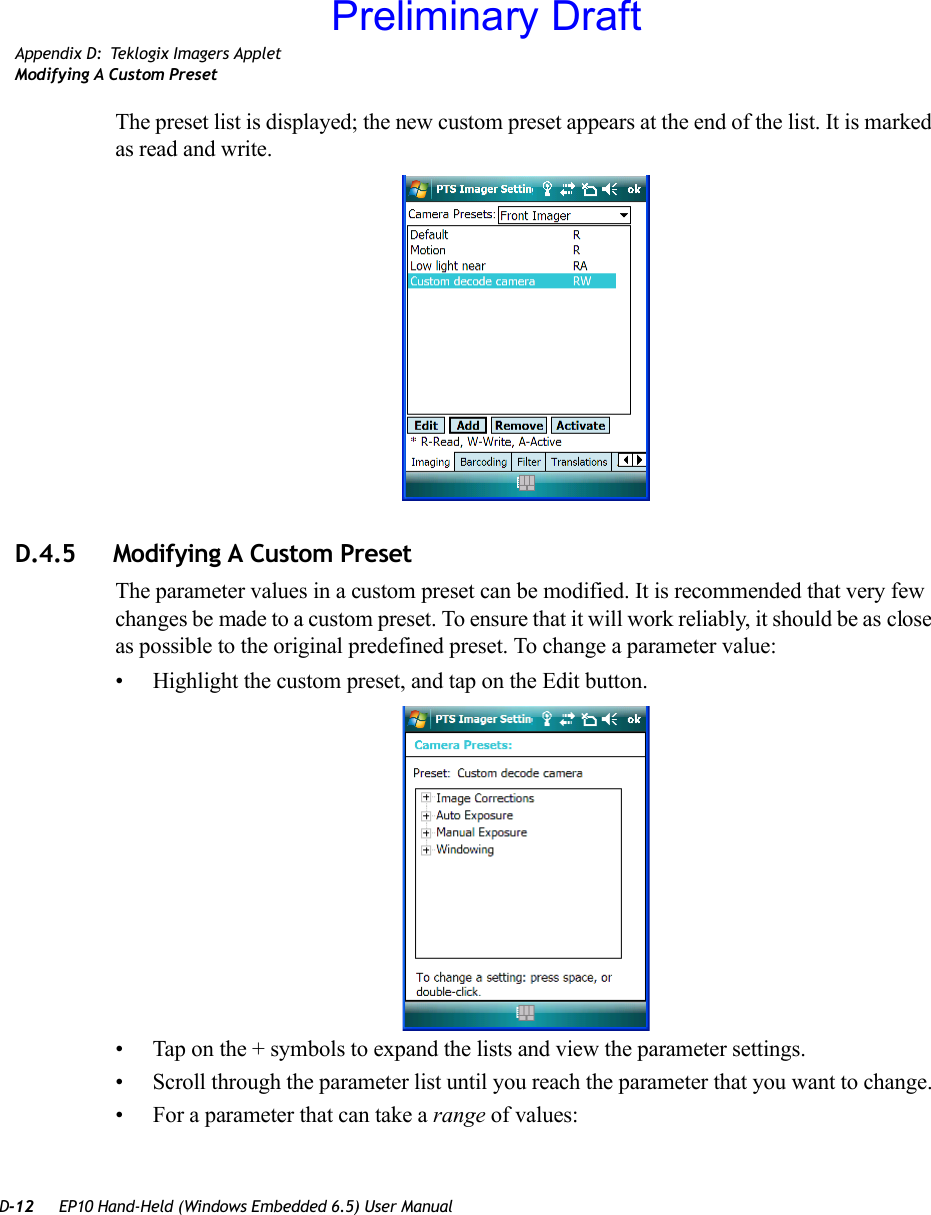
![Appendix D: Teklogix Imagers AppletRemoving A Custom PresetEP10 Hand-Held (Windows Embedded 6.5) User Manual D-9- Highlight the parameter and then press the [SPACE] key, or double-click on the parameter. Either method toggles between the two available values.• When you’ve completed your edits, tap on OK.The parameter list is displayed; the new value for the changed parameter is shown.• Tap on OK to exit to the preset list and save the changes.D.3.7 Removing A Custom Preset• Highlight the custom preset you want to delete, and tap on the Remove button.A window is displayed warning you that you are about to remove a preset.• Tap on Ye s to remove the preset or No to cancel the operation.D.4 Configuring The Bar Code Decoding Camera PresetsTo configure the bar code decoding camera presets:• Tap on Start>Settings>System tab.• Tap on the Barcoding tab.Figure D.5 Bar Code PresetsThis window lists all the presets, both predefined and the custom. Presets are identified as follows:• Predefined presets are marked as read-only. For a description, review “Predefined Pre-sets” on page D-2.• Custom presets are marked as read and write.• One preset – either predefined or custom – is marked as active.Preliminary Draft](https://usermanual.wiki/Psion/7515CA.Users-Manual/User-Guide-1515870-Page-357.png)
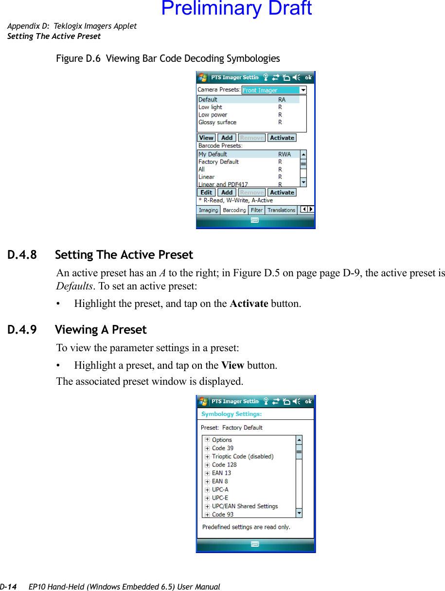
![Appendix D: Teklogix Imagers AppletRemoving A Custom PresetEP10 Hand-Held (Windows Embedded 6.5) User Manual D-13- Highlight the parameter, and then press the [SPACE] key or double-click the parameter.- An associated dialog box containing the valid range of values for the parameter and the current setting like the sample screen following is displayed.- Type a value in the field provided.• For a parameter that toggles between two values such as on or off and enabled or disabled:- Highlight the parameter and then press the [SPACE] key, or double-click on the parameter. Either method toggles between the two available values.• When you’ve completed your edits, tap on OK.The parameter list is displayed; the new value for the changed parameter is shown.• Tap on OK to exit to the preset list and save the changes.D.4.6 Removing A Custom Preset• Highlight the custom preset you want to delete, and tap on the Remove button.A window is displayed warning you that you are about to remove a preset.• Tap on Ye s to remove the preset or No to cancel the operation.D.4.7 Configuring The Bar Code Decoding SymbologiesTo configure the bar code decoding camera presets:• Tap on Start>Settings>System tab.• Tap on the Barcoding tab.Preliminary Draft](https://usermanual.wiki/Psion/7515CA.Users-Manual/User-Guide-1515870-Page-361.png)
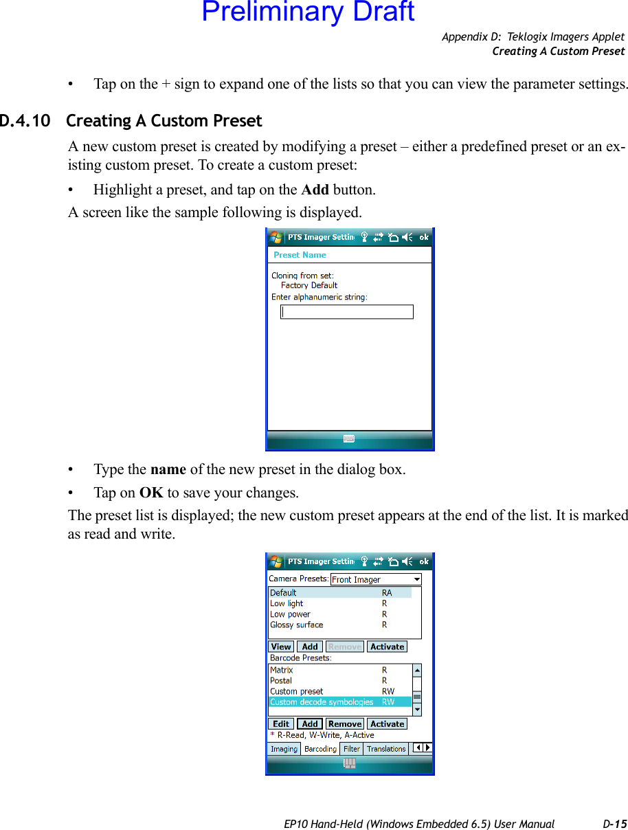
![D-16 EP10 Hand-Held (Windows Embedded 6.5) User ManualAppendix D: Teklogix Imagers AppletModifying A Custom PresetD.4.11 Modifying A Custom PresetThe parameter values in a custom preset can be modified. It is recommended that very few changes be made to a custom preset. To ensure that it will work reliably, it should be as close as possible to the original predefined preset. To change a parameter value:• Highlight the custom preset, and tap on the Edit button.• Tap on the + symbols to expand the lists and view the parameter settings.• Scroll through the parameter list until you reach the parameter that you want to change.• For a parameter that can take a range of values:- Highlight the parameter, and then press the [SPACE] key or double-click the parameter.Preliminary Draft](https://usermanual.wiki/Psion/7515CA.Users-Manual/User-Guide-1515870-Page-364.png)
![Appendix D: Teklogix Imagers AppletRemoving A Custom PresetEP10 Hand-Held (Windows Embedded 6.5) User Manual D-17- An associated dialog box containing the valid range of values for the parameter and the current setting like the sample screen following is displayed.- Type a value in the field provided.• For a parameter that toggles between two values such as on or off and enabled or disabled:- Highlight the parameter and then press the [SPACE] key, or double-click on the parameter. Either method toggles between the two available values.• When you’ve completed your edits, tap on OK.The parameter list is displayed; the new value for the changed parameter is shown.• Tap on OK to exit to the preset list and save the changes.D.4.12 Removing A Custom Preset• Highlight the custom preset you want to delete, and tap on the Remove button.A window is displayed warning you that you are about to remove a preset.• Tap on Ye s to remove the preset or No to cancel the operation.D.4.13 Configuring Symbologies in the Teklogix Imagers AppletAll changes made in the Symbologies Presets in the Imagers Applet are also made in the Scanners Applet. The Scanner Applet will reflect the settings of whichever Symbologies Preset is made active in the Imager Applet.Preliminary Draft](https://usermanual.wiki/Psion/7515CA.Users-Manual/User-Guide-1515870-Page-365.png)
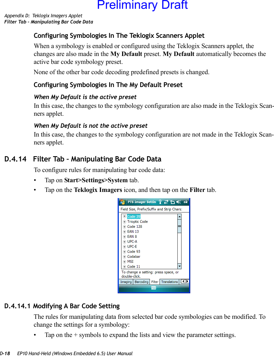
![Appendix D: Teklogix Imagers AppletFilter Tab – Manipulating Bar Code DataEP10 Hand-Held (Windows Embedded 6.5) User Manual D-19• Scroll through the parameter list until you reach the parameter that you want to change.• For a parameter that can take a range of values:- Highlight the parameter, and then press the [SPACE] key or double-click the parameter.- An associated dialog box containing the valid range of values for the parameter and the current setting like the sample screen following is displayed.- Type a value in the field provided.• For a parameter that takes a single character:- Highlight the parameter and then press the [SPACE] key, or double-click on the parameter. The following screen is displayed:• When you’ve completed your edits, tap on OK.Preliminary Draft](https://usermanual.wiki/Psion/7515CA.Users-Manual/User-Guide-1515870-Page-367.png)