Psion 7525BTB Bluetooth Module User Manual BC01b AN 047b 17JUL01
Psion Inc Bluetooth Module BC01b AN 047b 17JUL01
Psion >
Contents
- 1. Revised Part 1
- 2. Revised Part 2
- 3. Revised Part 3
Revised Part 2
BlueTest Instruction Manual
bc01-an-047b
© Copyright CSR Ltd 2001
This material is subject to CSR’s non-disclosure agreement.
Page 18 of 56
BlueCore
TM
01
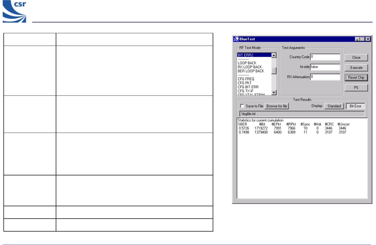
Title BIT ERR2
Summary
Enables the receiver with simplified hopping defined by Country
Code with a choice of low or high side modulation (hi-side), and
with a designated attenuation setting (RX Attenuation) as for
RXDATA2.
Returns information on bit errors to the host as those given for
BIT ERR1.
Related Test Spec
Name
None, but note that this test allows (as in BIT ERR1) the tests
RCV/CA/01/C and RCV/CA/02/C (sensitivity), RCV/CA/04/C
(blocking performance) to be performed with hopping on. This is
a more thorough test than that possible with the 7 Layers
equipment.
Test Arguments
Country Code = 0 to 3 (default 0)
hi-side = 0 or 1 (default = 0)
RX Attenuation = 0 to 15 (default = 0)
Note
With a second unit, execute CFG UAP/LAP to set BT address
then execute TXDATA2, then execute CFG UAP/LAP to set the
same BT address on the Equipment under Test (EUT) before
executing BIT ERR2.
Return Data Nine reports, each two uint32 values as for BIT ERR1.
Exit Click on Reset Chip.
BIT ERR2 Example Display
BlueTest Instruction Manual
bc01-an-047b
© Copyright CSR Ltd 2001
This material is subject to CSR’s non-disclosure agreement.
Page 19 of 56
BlueCore
TM
01
Loopback Test Mode
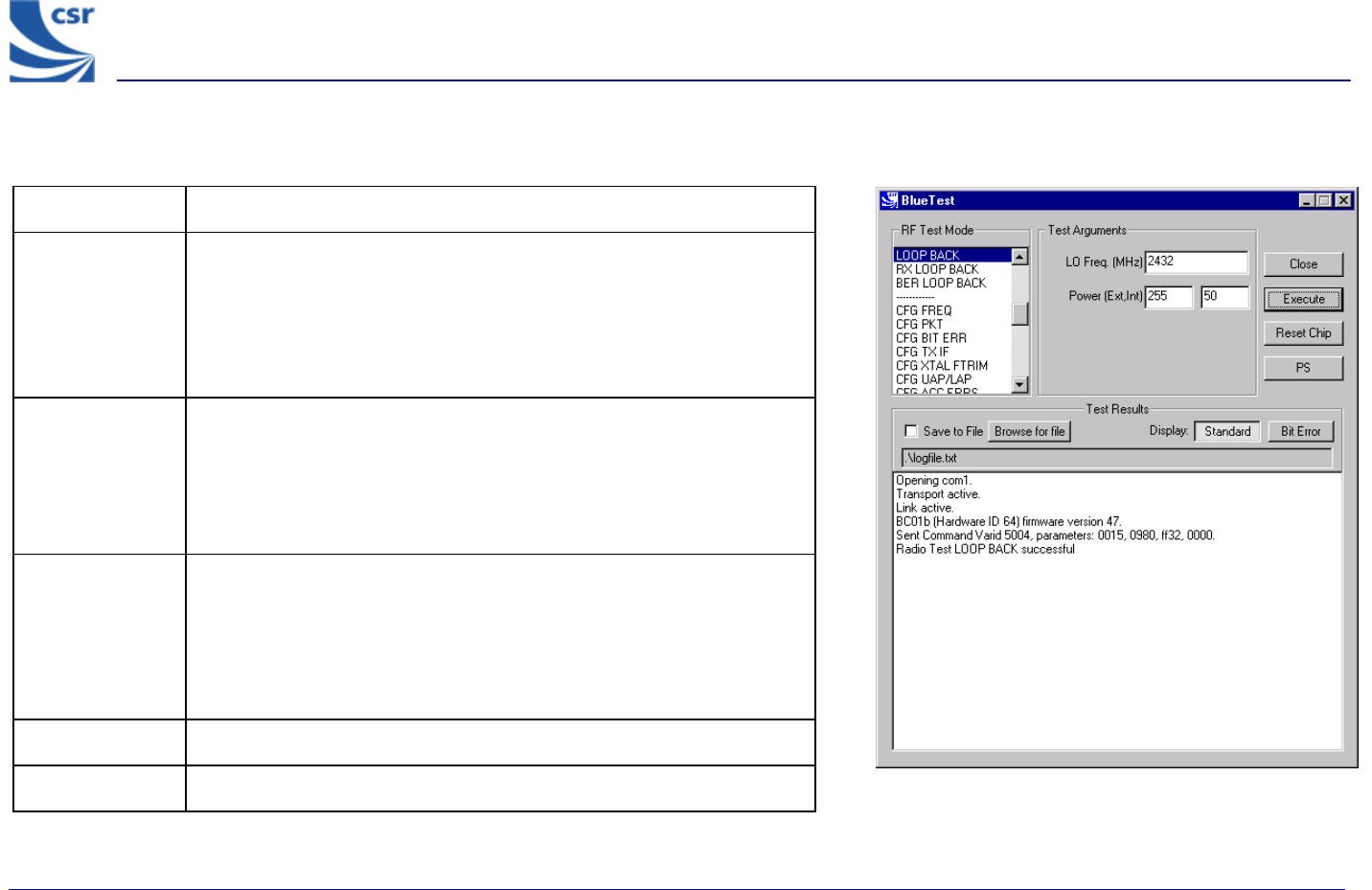
Title LOOP BACK
Summary
Receives data on LO Frequency for data packets and then retransmits
this data on the same channel at transmit level ‘lvl’. Highside
reception is off and attenuation is set to 0. Expected reception
frequency, txrx_freq (default = 12500 microsecs) with single slot
packets returned lb_offs after receipt (default = 1875 microsecs).
Defaults can be changed. See Configuration Commands section.
Related Test
Spec Name
None, but note that this test RCV/CA/01/C to RCV/CA/06/C to be
performed in loopback without using the LMP commanded loopback
test mode.
RCV/CA/01/C to RCV/CA/06/C to be performed in loopback, but
without using the LMP commanded loopback test mode.
Test Arguments
LO Freq (Carrier Frequency MHz)= 2402 to 2480 (default =
2432)
Power (Ext, Int) = gain of external amplifier (if present) and internal
amplifier. Ext value is specific to the design and Int value is 0 to 63
(Default = 50).
Return Data None
Exit Click on Reset Chip.
LOOP BACK Example Display
BlueTest Instruction Manual
bc01-an-047b
© Copyright CSR Ltd 2001
This material is subject to CSR’s non-disclosure agreement.
Page 20 of 56
BlueCore
TM
01
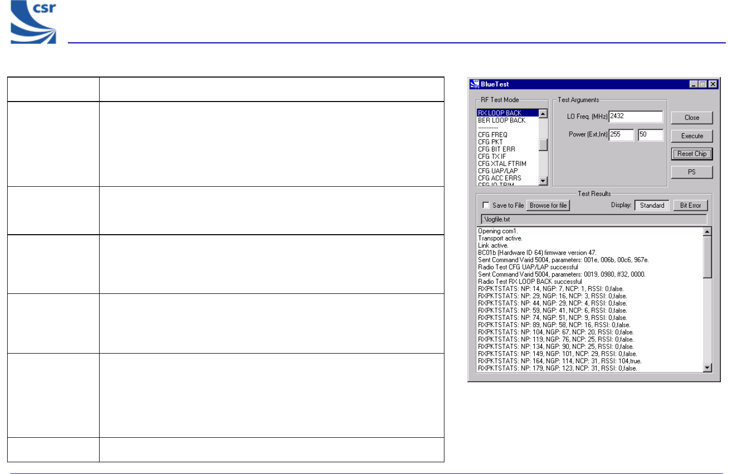
Title RX LOOP BACK
Summary Transmit PRBS9 data on LO Frequency at transmit level and listen for
transmissions in the next slot but one. Sends reports as RXDATA1 back to
the host once per second (configurable). Highside reception is off and
attenuation is set to 0. Default is single-slot packets (configurable with
config_freq). This is designed to be used with a second unit in
LOOP_BACK test mode.
Related Test
Spec Name None, but note that this test allows transmission to and reception from
Implementation under Test (IUT) in LOOP_BACK test mode with RSSI
and BER calculated from FEC.
Test Arguments LO Freq (Carrier Frequency MHz)= 2402 to 2480
Power (Ext, Int) = gain of external amplifier (if present) and internal
amplifier. Ext value is specific to the design and Int value is 0 to 63
(Default = 50).
Note With a second unit execute CFG UAP/LAP to set the Bluetooth address.
Execute LOOP BACK then execute CFG UAP/LAP to set the same BT
address on the Equipment under Test (EUT) before executing RX LOOP
BACK.
Return Data NP = Number of packets
NGP = Number of good packets
NCP = Number of corrected packets
RSSI = Received Signal Strength Indication
True = RSSI is reliable, otherwise false
Exit Click on Reset Chip.
RX LOOP BACK Example Display
BlueTest Instruction Manual
bc01-an-047b
© Copyright CSR Ltd 2001
This material is subject to CSR’s non-disclosure agreement.
Page 21 of 56
BlueCore
TM
01
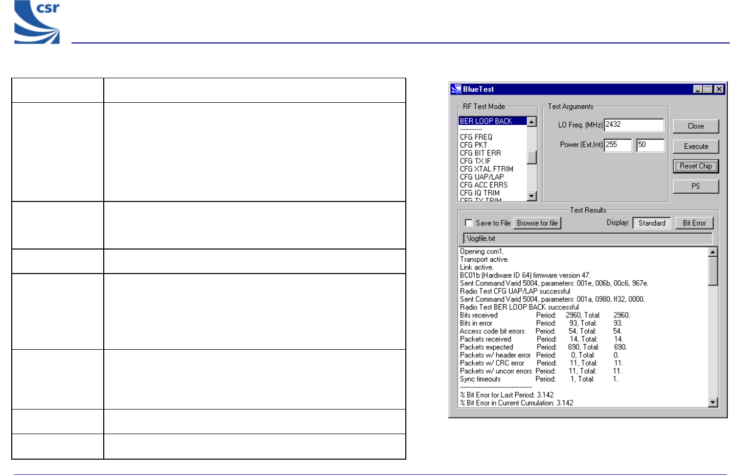
Title BER LOOP BACK
Summary
Transmit PRBS9 data on LO Frequency at transmit level
and listen for transmissions in the next slot but one. Sends
reports as BIT ERR1 back to the host once per second
(configurable). Highside reception is off and attenuation is set to
zero Default is single slot packets (configurable with
config_freq). Designed to be used with a second unit in
loop_back test mode.
Related Test
Spec Name
None, but note that this test allows transmission to and
reception from IUT in loopback test mode, with calculation of
BER to BT specification.
Called via BCSP channel 2
Test Arguments
LO Freq (Carrier Frequency MHz)= 2402 to 2480
Power (Ext, Int) = gain of external amplifier (if present) and
internal amplifier. Ext value is specific to the design and Int
value is 0 to 63 (Default = 50).
Note
With a second unit execute CFG UAP/LAP to set BT address
then execute LOOP BACK, then execute CFG UAP/LAP to set
the same BT address on the EUT before executing BER LOOP
BACK.
Return Data Nine reports as for BIT ERR1.
Exit Click on Reset Chip.
BER LOOP BACK Example Display
BlueTest Instruction Manual
bc01-an-047b
© Copyright CSR Ltd 2001
This material is subject to CSR’s non-disclosure agreement.
Page 22 of 56
BlueCore
TM
01
Configuration Commands
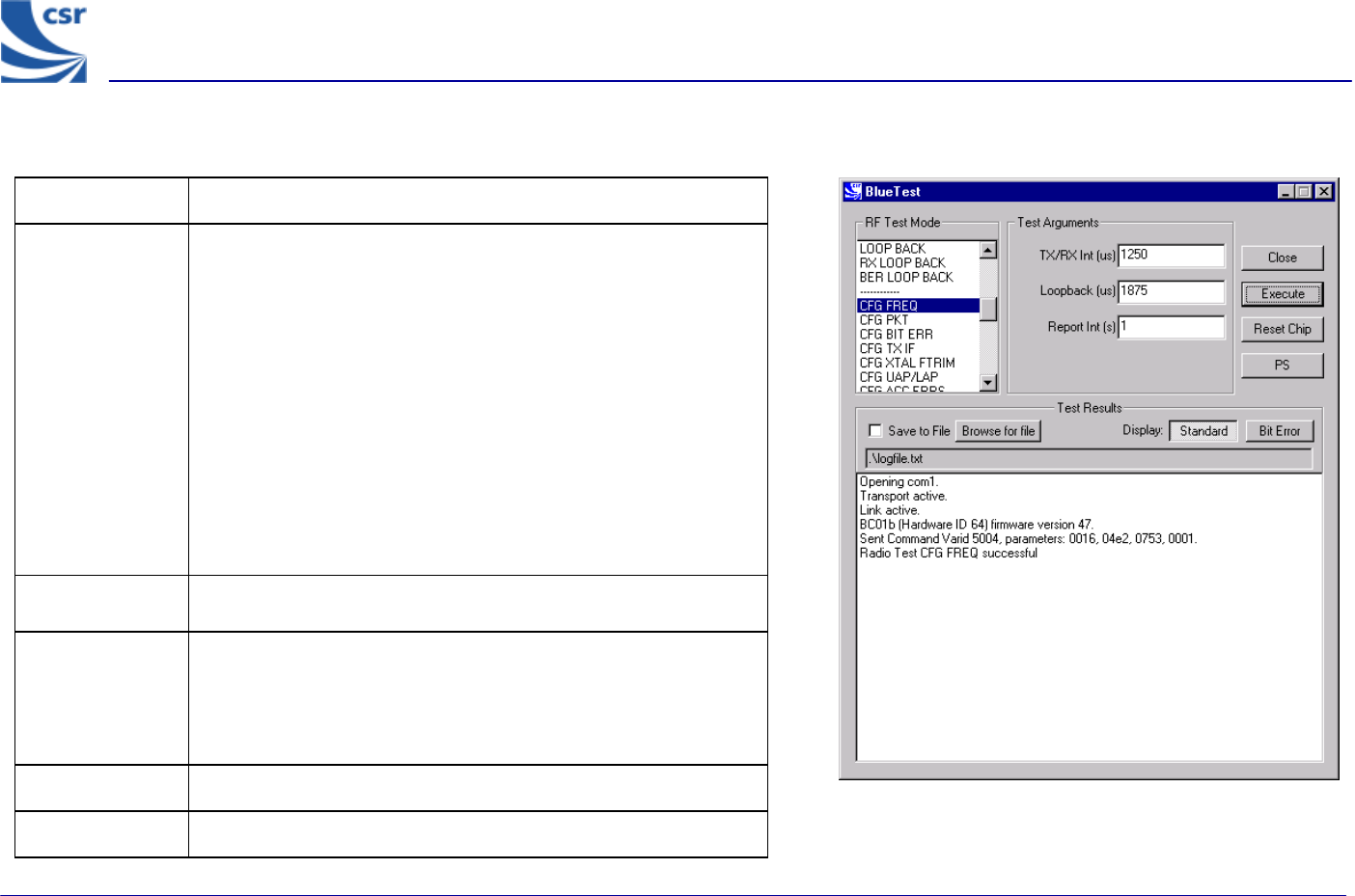
Title CFG FREQ
Summary
Sets three values used in deciding timing details of tests.
Tx/Rx Int (txrx_freq) sets the period in microseconds
between TX and RX events in RXDATA, TXDATA, BIT ERR and
LOOP BACK test modes. Default is 1250 (20 slots), maximum
65536. If passed as 0, current value unchanged.
Loopback (lb_offs) sets the offset in microseconds
between a reception event and retransmission of the data in
loopback. Default is 1875 (two slots later), must be less than
TX/Rx Int (txrx_freq). If passed as zero current value
unchanged.
Report Int(report_freqs) sets the time in seconds between
reports to host sent by RXDATA and BIT ERR functions. Default
1, if passed as 0 current value unchanged.
Related Test
Spec Name None
Test Arguments
TX/RX Int (µS) = 1 to 65535 (default = 1250)
Loopback (µS) = 1 to 65535 (default = 1875)
Report Int (S) = 1 to 65535 (default = 1)
Return Data None.
Exit Click on Reset Chip.
CFG FREQ Example Display
BlueTest Instruction Manual
bc01-an-047b
© Copyright CSR Ltd 2001
This material is subject to CSR’s non-disclosure agreement.
Page 23 of 56
BlueCore
TM
01
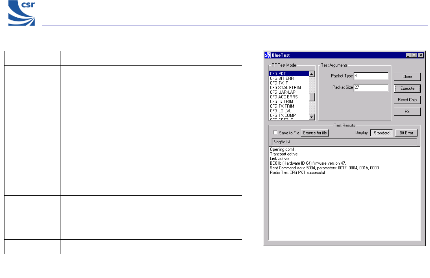
Title CFG PKT
Summary
Sets packet type and size for transmitter tests. It has no effect on
RX or LOOP BACK tests.
Packet Type (pkt-type) is the standard Bluetooth packet
type, 0-15 (12-13 not allowed). Any other number sets default:
DM5 for TXDATA1/2, DH5 for TXDATA3/4.
Packet Size (pkt_size) is the size of data in packet, from one
to maximum for type. If zero sets default: 20 bytes for TXDATA1/2,
192 bytes for TXDATA3/4.
Since the two values are connected both values must be set – no
default is inferred.
Related Test
Spec Name
None
Test Arguments
Packet Type = 0 to 15 (default = 4) (see Appendix 5)
Packet Size = 0 to 339 (default = 27)
Return data None
Exit Click on Reset Chip.
CFG PKT Example Display
BlueTest Instruction Manual
bc01-an-047b
© Copyright CSR Ltd 2001
This material is subject to CSR’s non-disclosure agreement.
Page 24 of 56
BlueCore
TM
01
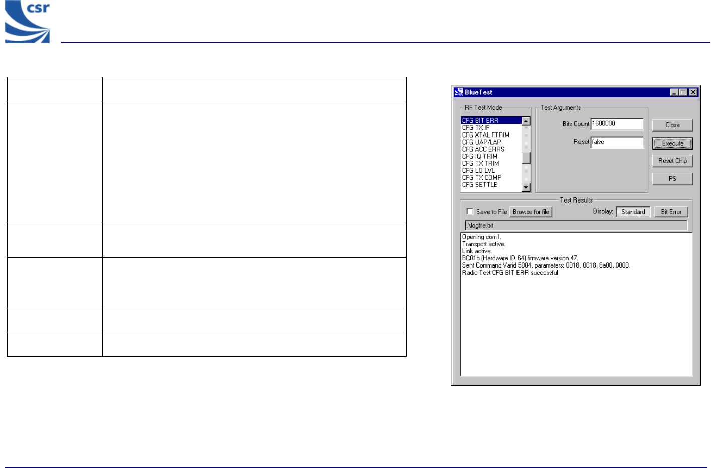
Title CFG BIT ERR
Summary
Sets two values used in bit error measurements.
If Bits Count (bits_count) is non-zero, the target for total
counters is set to this and total count resets at this value. If
passed as 0 current value, unchanged.
If Reset is not false and BIT ERR/2 is active, immediately resets
the counters for the total statistics, but not over the last report
period.
Related Test
Spec Name None
Test Arguments
Bits Count = 1 to 4.2 x 10⁹ (default = 1600000 Bit)
Reset = false (0) or true (1) (default = false)
Return Data None
Exit Click on Reset Chip.
CFG BIT ERR Example Display
BlueTest Instruction Manual
bc01-an-047b
© Copyright CSR Ltd 2001
This material is subject to CSR’s non-disclosure agreement.
Page 25 of 56
BlueCore
TM
01
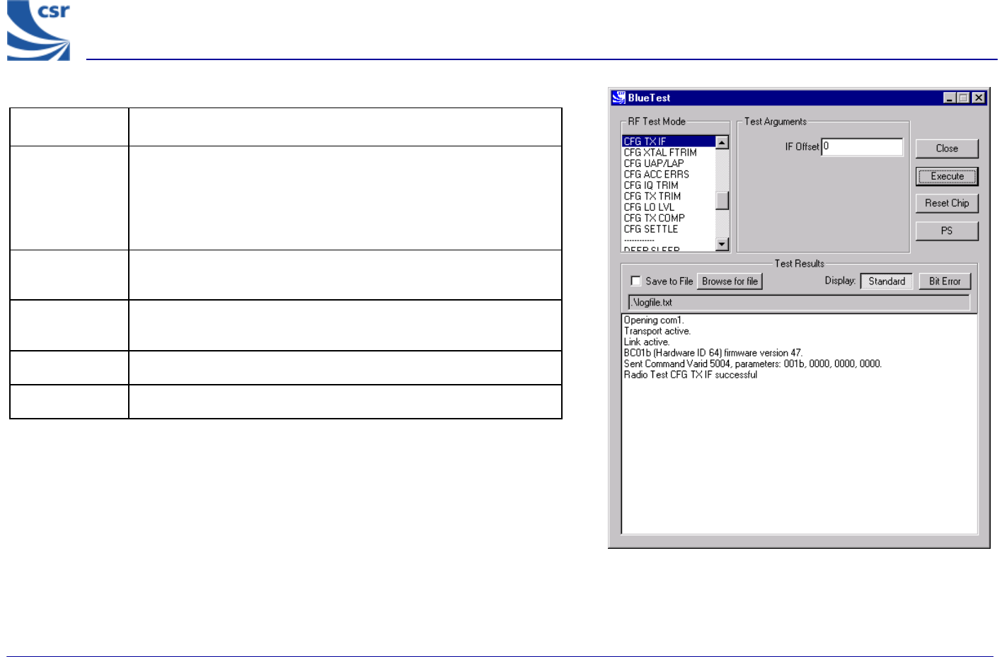
Title CFG TX IF
Summary
Sets the IF frequency used in transmit test modes. The target is
zero, but the stack currently uses a default of -1MHz.
Offset is a signed integer with a range from +5 to –5, in units of
0.5MHz.
Related Test
Spec Name None
Test
Arguments IF Offset = -5 to +5 (default = 0)
Return data None
Exit Click on Reset Chip.
CFG TX IF Example Display
BlueTest Instruction Manual
bc01-an-047b
© Copyright CSR Ltd 2001
This material is subject to CSR’s non-disclosure agreement.
Page 26 of 56
BlueCore
TM
01
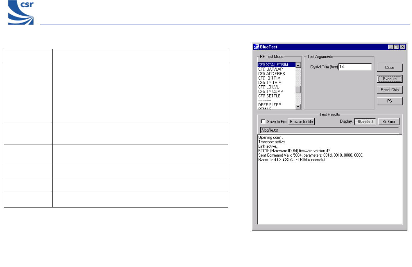
Title CFG XTAL FTRIM
Summary
Timing for BlueCore01 is controlled by a crystal. This requires
trimming for new hardware. This command can be used to set a
new trim value either before a radiotest command is started or
while a test is already in operation; the change takes effect
immediately.
Crystal Trim (xtal_ftrim) is a number between 0 and 63
inclusive. This is not a permanent change.
Related Test
Spec Name None
Test
Arguments Crystal Trim = 0 to 63 (typical = 27)
Note With Crystal Trim set to 0, the current settings will not change.
Return data None
Exit Click on Reset Chip.
CFG XTAL FTRIM Example Display
BlueTest Instruction Manual
bc01-an-047b
© Copyright CSR Ltd 2001
This material is subject to CSR’s non-disclosure agreement.
Page 27 of 56
BlueCore
TM
01
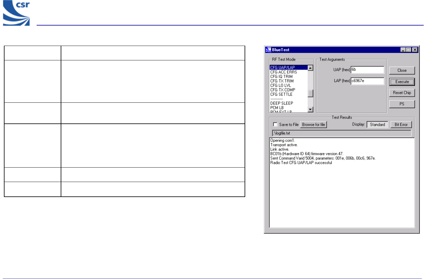
Title CFG UAP/LAP
Summary
Sets the UAP and LAP to be used in tests. BlueCore01 usually
uses its own Bluetooth Device address to determine the access
sync code, as if it is master of a piconet. The UAP and LAP are
the only parts used. This command allows a special UAP and LAP
to be used only in the test modes.
Related Test
Spec Name None
Test Arguments
Bluetooth Address:
UAP = 0 to FF (Default = 6b)
LAP = 0 to FFFFFF (Default = c6967e)
Return Data None
Exit Click on Reset Chip.
CFG UAP/LAP Example Display

BlueTest Instruction Manual
bc01-an-047b
© Copyright CSR Ltd 2001
This material is subject to CSR’s non-disclosure agreement.
Page 28 of 56
BlueCore
TM
01
Title CFG ACC ERRS
Summary The receiver uses a sliding correlator to determine that it has
matched the start of a packet. The receiver allows up to # of
errors (n_errs) before a match is rejected.
Related Test
Spec Name None
Test Arguments # of errors = 0 to 15 (default = 10)
Return Data None
Exit Click on Reset Chip.
CFG ACC ERRS Example Display
BlueTest Instruction Manual
bc01-an-047b
© Copyright CSR Ltd 2001
This material is subject to CSR’s non-disclosure agreement.
Page 29 of 56
BlueCore
TM
01
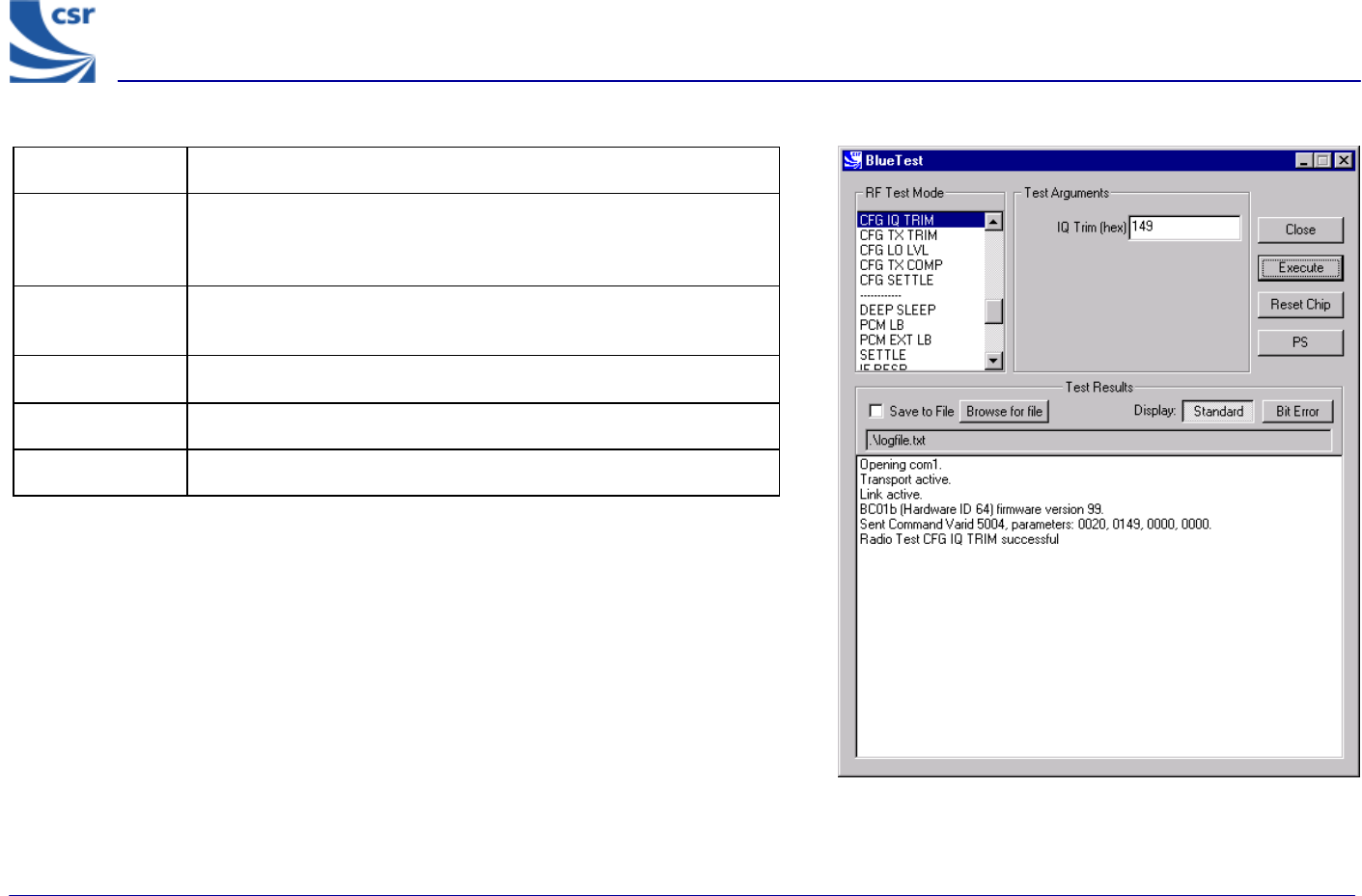
Title CFG IQ TRIM
Summary Sets the IQ Trim (trim) value overriding the value calculated by
the internal calibration algorithm. This command is not executed in
normal use.
Related Test
Spec Name None
Test Arguments IQ Trim = 0 to 511 (default 149 (hex))
Return Data None
Exit Click on Reset Chip.
CFG IQ TRIM Example Display
BlueTest Instruction Manual
bc01-an-047b
© Copyright CSR Ltd 2001
This material is subject to CSR’s non-disclosure agreement.
Page 30 of 56
BlueCore
TM
01
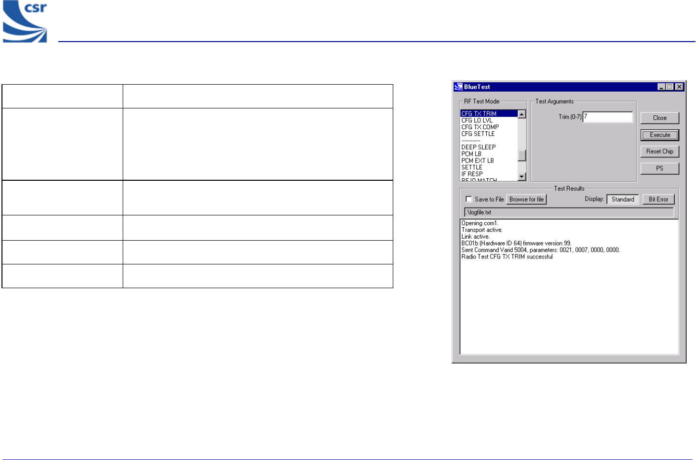
CFG TX TRIM Example Display
Title CFG TX TRIM
Summary
Sets the Active Member Address (am_addr) for the device
to be used in the header of all test transmissions to
am_addr. If the transmitter and receiver are used for the
same test, both devices will normally have to be set to the
same am_addr.
Related Test Spec
Name None
Test Arguments Trim (am_addr) = 0 to 7, Default = 7
Return Data None
Exit Click on Reset Chip.
BlueTest Instruction Manual
bc01-an-047b
© Copyright CSR Ltd 2001
This material is subject to CSR’s non-disclosure agreement.
Page 31 of 56
BlueCore
TM
01
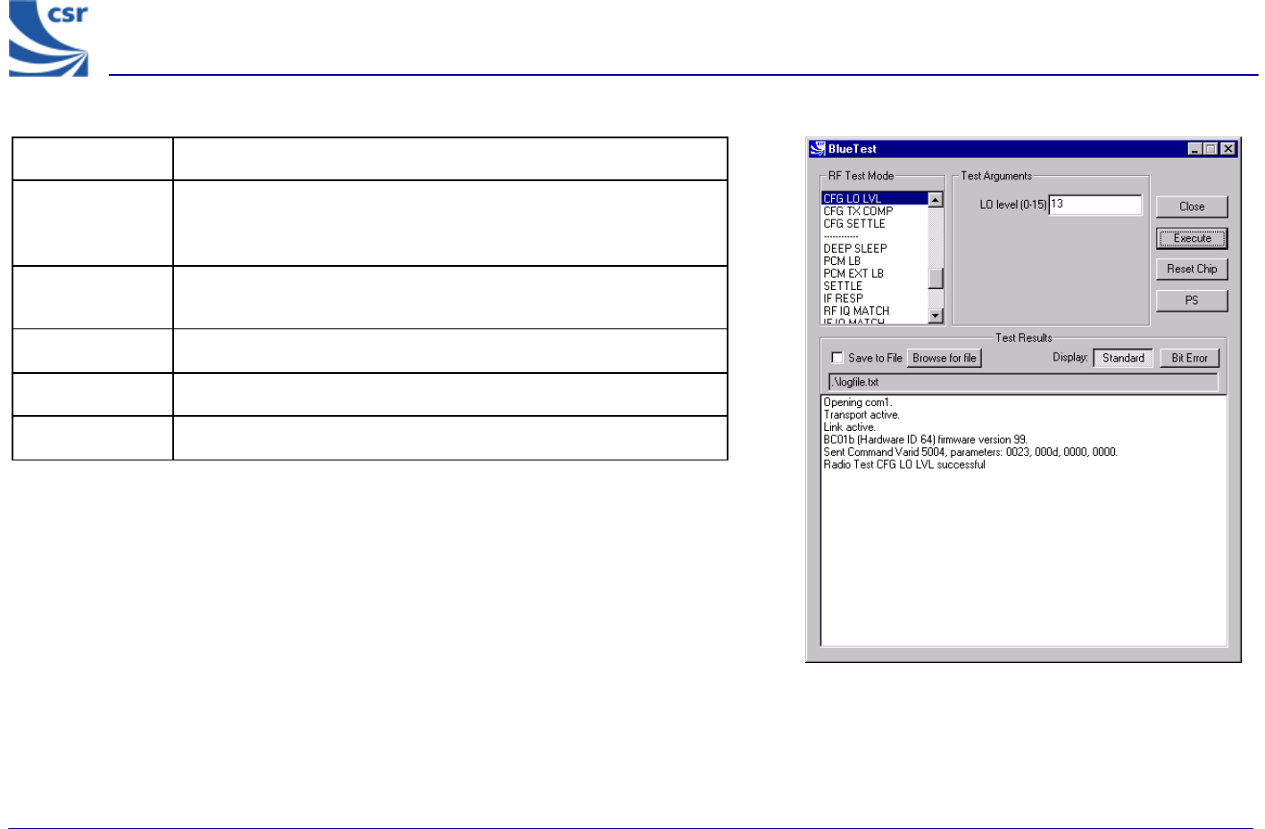
Title CFG LO LVL
Summary Sets the value of the Analogue Local Oscillator output level to LO
level (lvl), overriding the value calculated by the internal
calibration algorithm. This command is not executed in normal use.
Related Test
Spec Name None
Test Arguments LO level = 0 to 15 (default = 13)
Return Data None
Exit Click on Reset Chip.
CFG LO LVL Example Display
BlueTest Instruction Manual
bc01-an-047b
© Copyright CSR Ltd 2001
This material is subject to CSR’s non-disclosure agreement.
Page 32 of 56
BlueCore
TM
01
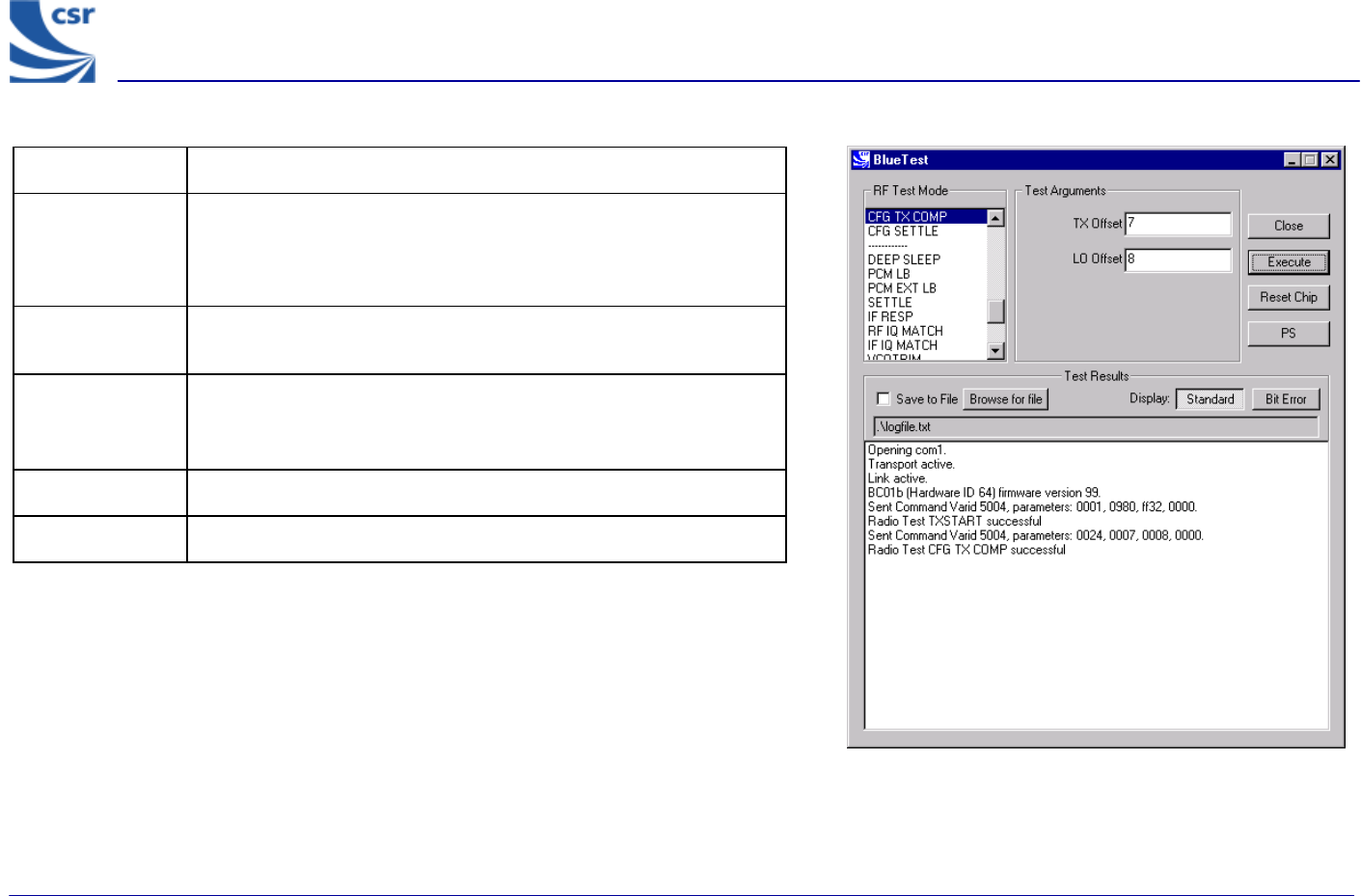
Title CFG TX COMP
Summary
Sets TX Offset (tx_offset) and LO Offset (lo_offset) for the
firmware’s algorithm, which sets the maximum power. Run
TXSTART before executing CFG TX COMP, otherwise there is no
transmit power to set.
Related Test
Spec Name None
Test Arguments
TX Offset, minimum = 0 (default = 7)
LO Offset, minimum = 0 (default = 8)
Return Data None
Exit Click on Reset Chip.
CFG TX COMP Example Display
BlueTest Instruction Manual
bc01-an-047b
© Copyright CSR Ltd 2001
This material is subject to CSR’s non-disclosure agreement.
Page 33 of 56
BlueCore
TM
01
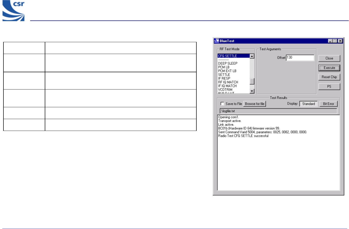
Title CFG SETTLE
Summary Sets the period (radio_on_offset) in microseconds
between turning the radio on and starting to transmit.
Related Test
Spec Name None
Test
Arguments Offset, minimum = 0 (default = 130)
Return Data None
Exit Click on Reset Chip.
CFG SETTLE Example Display
BlueTest Instruction Manual
bc01-an-047b
© Copyright CSR Ltd 2001
This material is subject to CSR’s non-disclosure agreement.
Page 34 of 56
BlueCore
TM
01
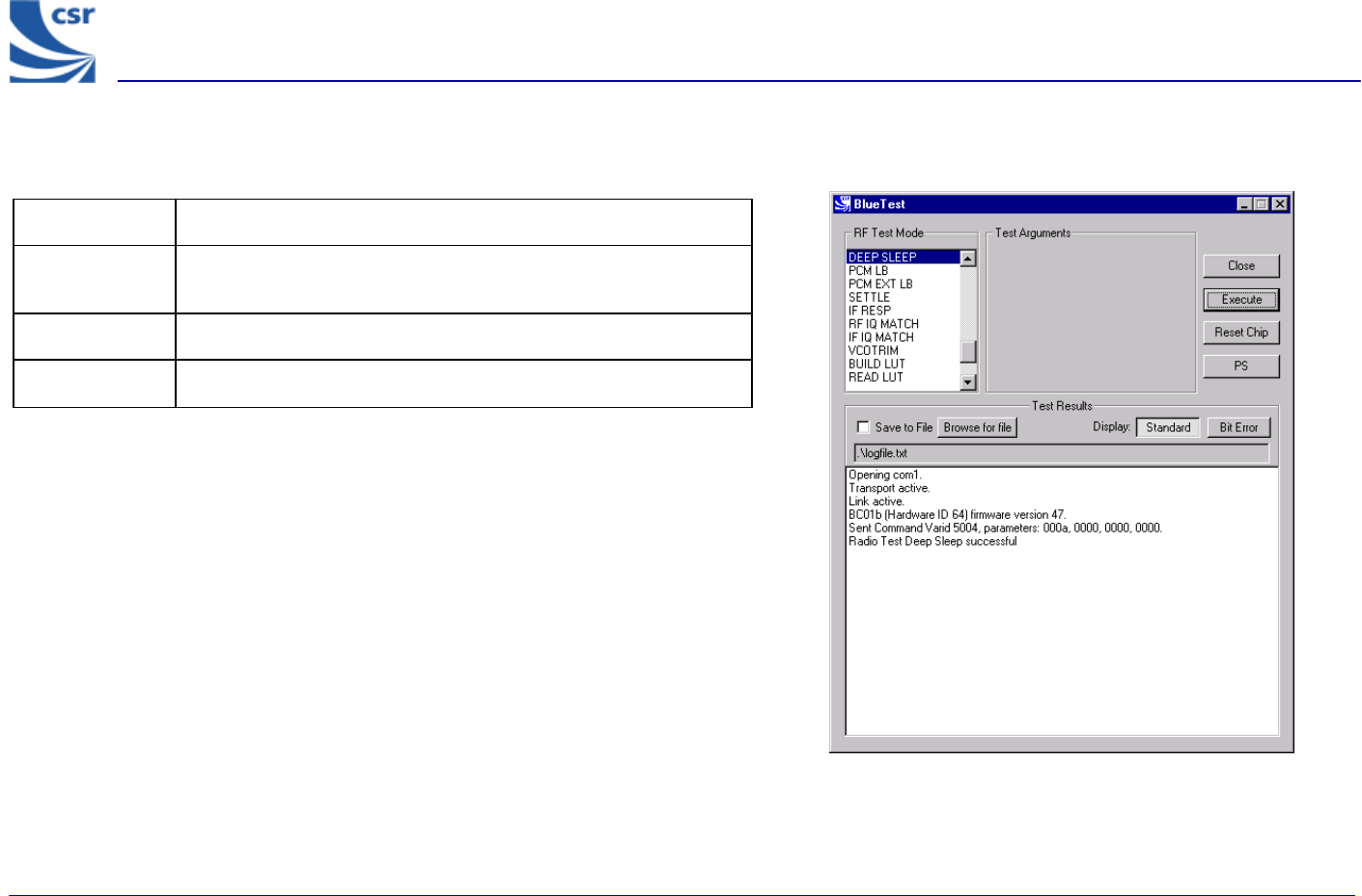
Built-in-Self Test (BIST) Routines
Title Deep Sleep
Summary Puts the chip into deep-sleep after a delay of half a second until
woken by reset or any activity on USB or UART interface.
Return Data None
Exit Click on Reset Chip or another routine being called.
Deep Sleep Example Display
BlueTest Instruction Manual
bc01-an-047b
© Copyright CSR Ltd 2001
This material is subject to CSR’s non-disclosure agreement.
Page 35 of 56
BlueCore
TM
01
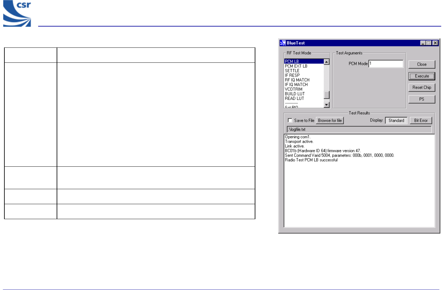
Title PCM LB
Summary
Sets the PCM into LOOP BACK mode, whereby the data read from
the PCM input is output again on the PCM out pin. The LOOP BACK
is via software and the buffers so there is a pipeline delay. The PCM
port mode is selectable.
If PCM Mode = 0, BlueCore01 is slave in normal 4-wire
configuration
If PCM Mode = 1, BlueCore01 is master in normal 4-wire
configuration
If PCM Mode = 2, BlueCore01 is master in Manchester encoded,
2-wire configuration.
Test
Arguments PCM Mode = 0 to 2 (default = 1)
Return Data None
Exit Click on Reset Chip or another routine being called.
PCM LB Example Display
BlueTest Instruction Manual
bc01-an-047b
© Copyright CSR Ltd 2001
This material is subject to CSR’s non-disclosure agreement.
Page 36 of 56
BlueCore
TM
01
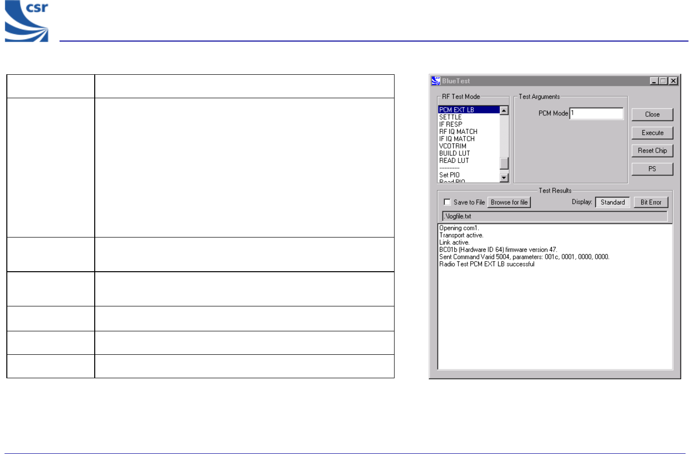
Title PCM EXTERNAL LOOPBACK
Summary
Sets the PCM into external LOOPBACK mode, whereby the data
written to the PCM output is read again on the input pin. A check is
made that the data read back is the same (up to usual codec
transformations) as that written. The LOOP BACK consists of 512
bytes of random data.
The PCM port mode is selectable as PCM Mode (pcm_mode),
which is the same as for PCM LB
(radiotest_pcm_loop_back)
The external LOOP BACK may be a simple wire.
Related Test
Spec Name None
Note On the Casira under test, set CN8 jumper to Codec BYP and on
header CN12 link pins 10 and 11.
Test Arguments PCM Mode = 0 to 2 (default = 1)
Return Data None
Exit Click on Reset Chip.
PCM EXT LB Example Display
BlueTest Instruction Manual
bc01-an-047b
© Copyright CSR Ltd 2001
This material is subject to CSR’s non-disclosure agreement.
Page 37 of 56
BlueCore
TM
01
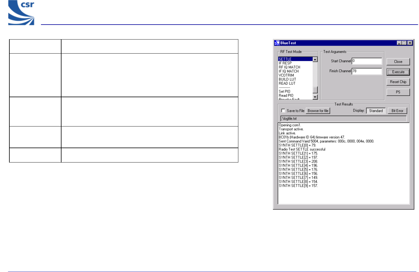
Title SETTLE
Summary
Builds the LUT as normal, then does a step from Start Channel
(chan1) to Finish Channel (chan2), while the synthesiser is
running. It digitises the synthesiser (LO_TUNE) error
voltage at intervals of 10 – 20µs over the next 200µs and
writes the results to an array.
Test Arguments
Start Channel (chan1) = 0 to 78 (default 0)
Finish Channel (chan2) = 0 to 78 (default 78)
Return Data A sequence of ten reports of the synthesiser (LO_TUNE) error
voltage over the next 200µs.
Exit Click on Reset Chip or another routine being called.
SETTLE Example Display
BlueTest Instruction Manual
bc01-an-047b
© Copyright CSR Ltd 2001
This material is subject to CSR’s non-disclosure agreement.
Page 38 of 56
BlueCore
TM
01
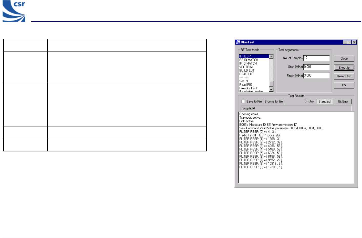
Title IF RESP
Summary
Sweeps transmit IF carrier frequency over designated number of
samples (n_samples) within range (0-3MHz maximum) and
measures RSSI. Returns table of RSSI value against frequency
offset to characterise IF filter response.
Test
Arguments
No. of Samples(n_samples) = 0 to 65535 (default = 10)
Start (lo_offset) = 0 to 3MHz (default 0.001 MHz)
Finish (hi_offset) = 0 to 3 MHz (default = 3.000
MHz. Must be greater than lo_offset)
Return Data A sequence of reports of RSSI and frequency offset.
Exit Click on Reset Chip.
IF RESP Example Display
BlueTest Instruction Manual
bc01-an-047b
© Copyright CSR Ltd 2001
This material is subject to CSR’s non-disclosure agreement.
Page 39 of 56
BlueCore
TM
01
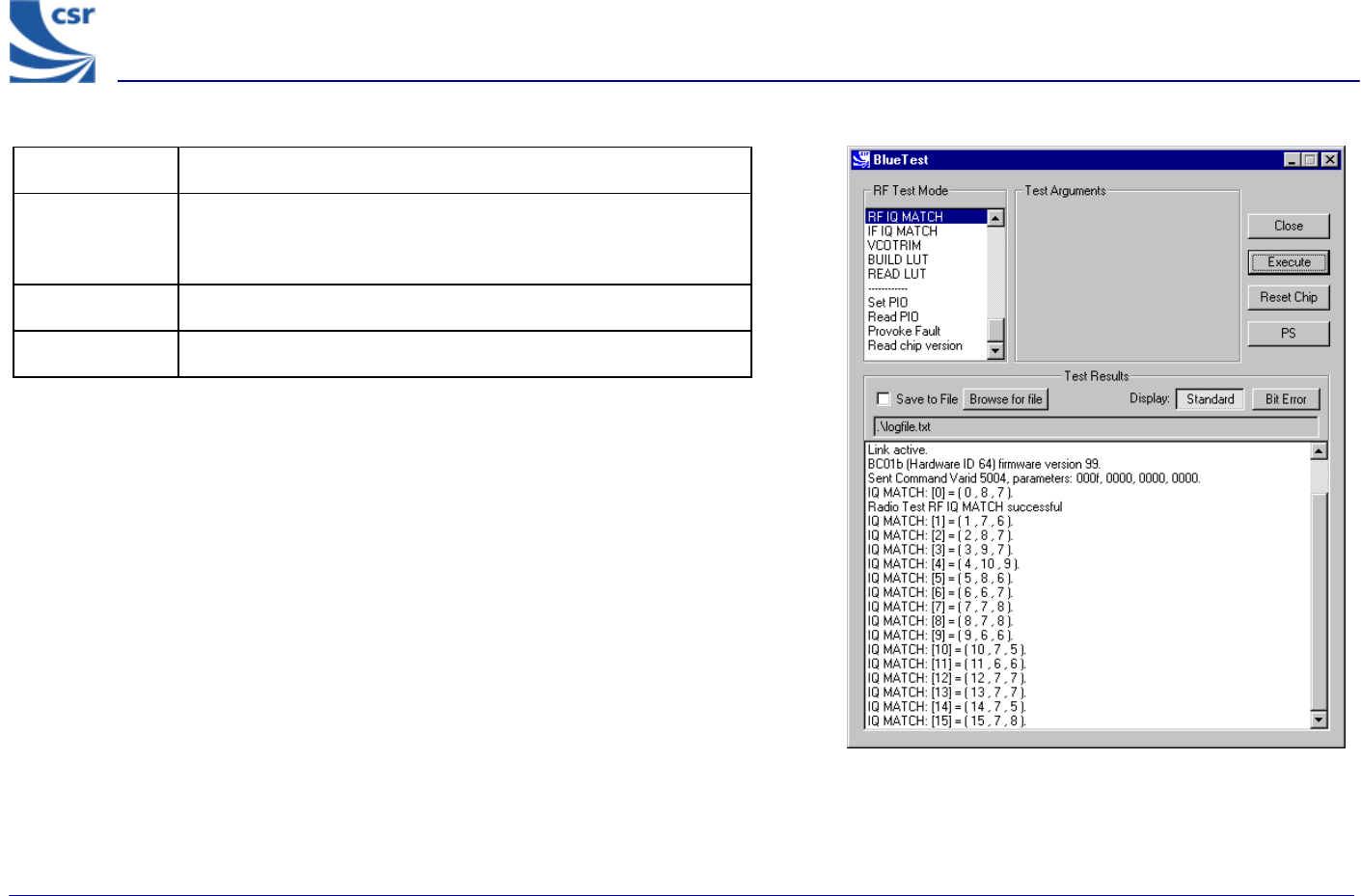
Title RF IQ MATCH
Summary Measures RF IQ match by injecting test signal, sweeping IQ trim
and measuring RSSI for on-channel and image. Returns array of
IQ measurements against IQ trim.
Return Data An array of 16 IQ measurements against IQ trim.
Exit Click on Reset Chip.
RF IQ MATCH Example Display