Psion 75273RADA Cellular TX User Manual 7535 G2 Hand Held Computer
Psion Inc Cellular TX 7535 G2 Hand Held Computer
Psion >
Contents
- 1. Users Manual Revision 033107
- 2. Users Manual Part 1
- 3. Users Manual Part 2
Users Manual Part 2

WORKABOUT PRO G2 Hand-Held With Windows Embedded CE 5.0 User Manual 193
Chapter 5: Configuration
Imager
Setting this parameter to on allows the imager to make automatic gain, integration
and illumination adjustments based on ambient light before capturing the bar code.
If the adjustment is insufficient, further adjustments are made automatically before
another image is captured.
Fast Converge
Note: “Auto Exposure” must be set to ‘on’ in order for this parameter
to function.
Keep in mind that while this parameter can improve imager performance,
“Fast Converge” increases battery power consumption.
Setting this parameter to on speeds the “Auto Exposure” process. It allows the
imager to rapidly snap a number of bar code capture attempts while finding ideal
values for gain, integration and illumination.
Max Gain, Max Integration And Max Illumination
Important: These parameter values should only be changed by qualified Psion
Teklogix personnel.
These parameters represent internal values used by the 2D imager. The “Auto
Exposure” parameter automatically adjusts the “Max Gain”, “Max Integration” and
“Max Illumination” parameters to produce the best bar code read. Keep in mind that
“Auto Exposure” must be set to on in order for these parameter values to be
automatically adjusted.
Double-tapping on any of these parameters displays an associated dialog box in
which an allowable range is displayed: Max Gain – 357 to 7920, Max Integration –
0 to 65535, Max Illumination – 0 to 7.
Decoder Timeout
The decoder is a set of algorithms that examine the image and attempt to find the bar
codes, and then turn the pixels into data that the computer can use—this process
takes time. “Decoder Timeout” limits the amount of time the decoder will spend
attempting to decode an image, and forces it to stop and grab a new image, which
will probably be easier to decode.
Note: When decoding multiple bar codes in one image, the value assigned to
‘Decoder Timeout’ should be increased to 200ms/extra bar code after the

Chapter 5: Configuration
Imager
194 WORKABOUT PRO G2 Hand-Held With Windows Embedded CE 5.0 User Manual
first.
Adaptive Windowing
“Adaptive Windowing” is an advanced technique used to speed up bar code
recognition in certain applications. This parameter automatically reduces the size of
the window to the user-programmed window size when it successfully decodes
(which reduces decode time the next time it is used), but increases it to the full size
window (1280x1024 for SX5303) on a failed decode.
Note: This feature assumes that you have reached an understanding about how
the device operates in your application, and that, after a learning period,
operators will get used to using the imager in one particular way. It also
assumes that a trained operator will usually only have near miss scenar-
ios.
Constant Illumination
“Constant Illumination” is used to reduce the intrusiveness of the device’s
illumination on the observer. Instead of the illumination turning on and off every
time the device attempts a decode (2-4 times per second), the illumination stays on
from the time the trigger is pulled until a decode is successful. This feature is useful
in low light environments, since it will also reduce the distraction that the
illumination can have on nearby co-workers.
5.11.5.3 Code 39 Settings
Enabled
Set this parameter to on to enable “Code 39”.
Field Size/Char
Refer to page 143 for details.
5.11.5.4 Code 128 Settings
Enabled
Set this parameter to on to enable “Code 128”.
Field Size/Char
Refer to page 143 for details.

WORKABOUT PRO G2 Hand-Held With Windows Embedded CE 5.0 User Manual 195
Chapter 5: Configuration
Imager
5.11.5.5 EAN 13
Enabled
Set this parameter to on to enable “EAN 13”.
Addendum
An addendum is a separate bar code, supplementary to the main bar code.
This parameter provides three options: Disabled, Optional and Required.
Depending on the value chosen for this parameter, an addendum is recognized
or ignored.
• Double-tap on Addendum to display a dialog box listing your options.
• Highlight an item, and tap on OK.
When “Addendum” is set to Disabled, the scanner does not recognize an
addendum. If this parameter is set to Optional, the scanner searches for
an addendum and if one exists, appends it to the main bar code. When the
parameter is set to Required, the scanner does not accept the main bar code
without an addendum.
Note: Setting “Addendum” to ‘Optional’ reduces performance. It should only
be chosen if at least some of the bar codes being read have addendums.
Prefix/Suffix
Refer to “Prefix/Suffix” beginning on page 144.
5.11.5.6 EAN 8
Enabled
Set this parameter to on to enable “EAN 8”.
Addendum
Refer to “Addendum” on page 195.
Prefix/Suffix
Refer to “Prefix/Suffix” beginning on page 144.
Chapter 5: Configuration
Imager
196 WORKABOUT PRO G2 Hand-Held With Windows Embedded CE 5.0 User Manual
5.11.5.7 UPC A
Enabled
Set this parameter to on to enable “UPC A”.
Addendum
Refer to “Addendum” on page 195.
Prefix/Suffix
Refer to “Prefix/Suffix” beginning on page 144.
5.11.5.8 UPC E
Enabled
Set this parameter to on to enable “UPC E”.
Addendum
Refer to “Addendum” on page 195.
Prefix/Suffix
Refer to “Prefix/Suffix” beginning on page 144.
5.11.5.9 Code 93
Enabled
Set this parameter to on to enable “Code 93”.
Field Size/Char
Refer to page 143 for details.
5.11.5.10 Codabar
Enabled
Set this parameter to on to enable “Codabar”.
Field Size/Char
Refer to page 143 for details.

WORKABOUT PRO G2 Hand-Held With Windows Embedded CE 5.0 User Manual 197
Chapter 5: Configuration
Imager
5.11.5.11 Interleaved 2 of 5
Enabled
Set this parameter to on to enable “Interleaved 2 of 5”.
Field Size/Char
Refer to page 143 for details.
5.11.5.12 RSS Code (Reduced Space Symbology)
Enable
Setting this parameter to on enables “RSS Code” scanning capability.
Field Size/Char
Refer to page 143 for details.
5.11.5.13 Composite
Important: To successfully read this type of bar code, the two types of symbolo-
gies included in a composite bar code must be enabled.
Enabled
Set this parameter to on to enable “Composite” bar codes.
5.11.5.14 PDF-417
Enable
Setting this parameter to on enables PDF-417 two dimensional (2D) coding.
Field Size/Char
Refer to page 143 for details.
Chapter 5: Configuration
Imager
198 WORKABOUT PRO G2 Hand-Held With Windows Embedded CE 5.0 User Manual
5.11.5.15 Micro PDF-417
Enable
Setting this parameter to on enables “Micro PDF-417” bar code scanning. Micro
PDF-417 is a multi-row symbology that is useful for applications requiring greater
area efficiency but lower data capacity than PDF-417.
Field Size/Char
Refer to page 143 for details.
5.11.5.16 2D Data Matrix
Enable
Set this parameter to on to enable “Data Matrix”.
Field Size/Char
Refer to page 143 for details.
5.11.5.17 2D QR Code
Enabled
Set this parameter to on to enable “2D QR Code”.
Field Size/Char
Refer to page 143 for details.
5.11.5.18 2D Maxicode
Enabled
Set this parameter to on to enable “2D Maxicode”.
Field Size/Char
Refer to page 143 for details.
5.11.5.19 2D Aztec
Enabled
Set this parameter to on to enable “Aztec”.
WORKABOUT PRO G2 Hand-Held With Windows Embedded CE 5.0 User Manual 199
Chapter 5: Configuration
Imager
Field Size/Char
Refer to page 143 for details.
5.11.5.20 Postal: PlaNET
Enabled
Set this parameter to on to enable “Postal: PlaNET”.
Field Size/Char
Refer to page 143 for details.
5.11.5.21 Postal: PostNET
Enabled
Set this parameter to on to enable “Postal: PostNET”.
Field Size/Char
Refer to page 143 for details.
5.11.5.22 Postal: Australian
Enabled
Set this parameter to on to enable “Postal: Australian”.
Field Size/Char
Refer to page 143 for details.
5.11.5.23 Postal: Japanese
Enabled
Set this parameter to on to enable “Postal: Japanese”.
Field Size/Char
Refer to page 143 for details.
Chapter 5: Configuration
Options
200 WORKABOUT PRO G2 Hand-Held With Windows Embedded CE 5.0 User Manual
5.11.5.24 Postal: Korean
Enabled
Set this parameter to on to enable “Postal: Korean”.
Field Size/Char
Refer to page 143 for details.
5.11.5.25 Postal: Royal
Enabled
Set this parameter to on to enable “Postal: Royal”.
Field Size/Char
Refer to page 143 for details.
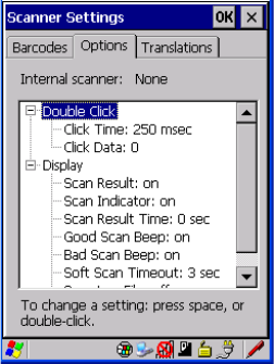
5.11.6 Options
This tab allows you to tailor the double-click parameters and the display options
associated with your scanner.
WORKABOUT PRO G2 Hand-Held With Windows Embedded CE 5.0 User Manual 201
Chapter 5: Configuration
Options
5.11.6.1 Double Click Parameters
Click Time (msec)
This parameter controls the maximum gap time (in milliseconds) for a double-click.
If the time between the first and second clicks of the scanner trigger is within this
time, it is considered a double-click. The allowable range is 0 to 1000. A value of
zero disables this feature.
A double-click produces different results depending on whether or not a value is
assigned in the “Click Data” parameter. When a value is not assigned for the “Click
Data”, double-clicking the scanner trigger overrides the target dot delay set in the
“Dot Time” parameter and initiates a normal scan sweep. If a value is assigned for
the “Click Data” parameter, double-clicking the scanner trigger inserts the “Click
Data” value rather than initiating a scan.
Click Data
For both integrated and external scanners, this parameter determines which
character is sent to the application installed in your hand-held following a
double-click. A dialog box appears, asking that you press the key you want to insert.
The ASCII/Unicode key value of the keypress is displayed.
5.11.6.2 Display Parameters
Scan Result
When this parameter is enabled, the type of bar code and the result of the scan
appear on the screen. Note that this information is only displayed after a successful
decode and is visible only while the scanner trigger is pressed. When the trigger is
released, this information is cleared from the screen.
Scan Indicator
When this parameter is enabled, the laser warning logo appears on the display
whenever the scanner is activated.
Scan Result Time (sec)
The value assigned to the “Scan Result Time (sec)” parameter determines how long
the scan results of a successful scan are displayed on the screen. Time is measured in
seconds, and a value of “0” (zero) disables the parameter. When you choose this
option, a dialog box appears where you can enter a value.

Chapter 5: Configuration
Options
202 WORKABOUT PRO G2 Hand-Held With Windows Embedded CE 5.0 User Manual
Note: To remove the scan result from the screen before the “Result Time” has
expired, point the scanner away from the bar code and press the trigger.
Good Scan Beep And Bad Scan Beep
These parameters determine whether or not the hand-held emits an audible scanner
‘beep’ when a good (successful) scan or a bad (unsuccessful) scan is performed. Set
these parameters to either on to enable the beeper or off to disable it.
Soft Scan Timeout
This parameter is used by the SDK “Scan” function (soft-scan: starting a scan
session via the SDK function, instead of a physical user trigger press). The value
assigned to this parameter determines the soft-scan timeout from 1 to 10 sec.
(default is 3 sec.).
Scan Log File
If this parameter is enabled, the input barcode and the modified/translated output bar
code are logged in the file \Flash Disk\ScanLog.txt. Keep in mind that if the “Scan
Log File” is enabled, there is a slight performance effect when performing multiple
scans since the log file is written to persistent storage.
WORKABOUT PRO G2 Hand-Held With Windows Embedded CE 5.0 User Manual 203
Chapter 5: Configuration
Translations Tab
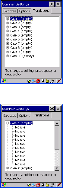
5.11.7 Translations Tab
The Translations tab allows you to define up to 10 cases, each consisting of up to 10
rules in sequential order. Only one case will be applied to a bar code and a case will
only be applied if all rules specified in the case are successful – if a rule within a
case fails, the entire case fails.
•In the Translation tab, tap on the Case # to create rules.
Chapter 5: Configuration
Translations Tab
204 WORKABOUT PRO G2 Hand-Held With Windows Embedded CE 5.0 User Manual
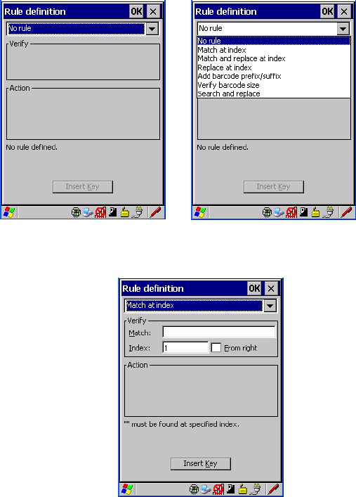
• Tap on the No rule dropdown menu to display the rules.
When you choose a rule, an associated screen is displayed in which you can define
the rule.

WORKABOUT PRO G2 Hand-Held With Windows Embedded CE 5.0 User Manual 205
Chapter 5: Configuration
SNMP (Simple Network Management Protocol) Setup
5.11.7.1 Case Rules
The case rules are defined as follows:
• No rule – ignored.
• Search and replace – replaces all instances of the match string. (Note that
this rule cannot fail.)
• Match at index – matches the match string at a specified index.
• Match and replace at index – matches the match string at a specified index
and replaces/changes it.
• Replace at index – replaces/changes unspecified data in a given range.
• Add barcode prefix/suffix – adds a global prefix or suffix.
• Verify barcode size – verifies the bar code size. This rule should generally
be assigned first, before creating subsequent rules.
Note: Keep in mind that the effects of previously applied rules must be taken
into account when creating subsequent rules. For example, if the bar code
size is important, it should be checked before any rules that might change
the size are applied.
Translation information about the status of each case/rule is displayed in the scan
log file (see “Scan Log File” on page 202) when enabled. This is useful if a case
fails, and you are trying to determine why a rule is failing.
5.12 SNMP (Simple Network Management Protocol)
Setup
Simple Network Management Protocol (SNMP) is the protocol used to monitor and
manage devices attached to a TCP/IP network (providing they support SNMP).
SNMP uses Management Information Bases (MIBs) that define the variables an
SNMP Network Management Station can access. Each product has a defined set of
MIBs that determine how SNMP operates, the type of access allowed and so on.
All Psion Teklogix products support the TEKLOGIX-GENERIC-MIB—a MIB that
defines some common features across Psion Teklogix products.
Chapter 5: Configuration
Contact Tab
206 WORKABOUT PRO G2 Hand-Held With Windows Embedded CE 5.0 User Manual
All devices also support MIB-II, a management information base that defines the
common features of TCP/IP networks. The SNMP Agent software embedded in the
WORKABOUT PRO G2 product supports SNMPv1 (RFC 1157).
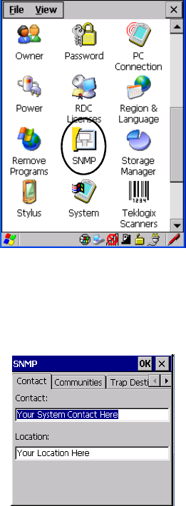
•In the Control Panel, choose the SNMP icon.
Figure 5.20 SNMP Icon
5.12.1 Contact Tab
The SNMP dialog box is displayed.
Contact
This field identifies the contact person for this managed node along with
information about how to get in touch with this person. The content of this
parameter is accessible through MIB-II’s sysContact object.
WORKABOUT PRO G2 Hand-Held With Windows Embedded CE 5.0 User Manual 207
Chapter 5: Configuration
Communities Tab
Location
This parameter is used to identify the physical location of this node (e.g., Warehouse
A: Pillar 32B). The content of this parameter is accessible through MIB-II’s
sysLocation object.
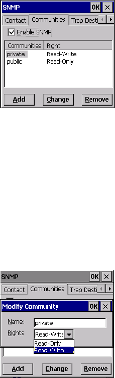
5.12.2 Communities Tab
The Communities tab allows you to limit access to SNMP-managed devices to those
SNMP Managers with matching “community names”, as specified by RFC 1157.
Enable SNMP
Enabling Enable SNMP allows the device to respond to SNMP queries and to send
Traps. After enabling this option and rebooting the device, the SNMP Agent will
automatically start up. To disable this feature, remove the check mark from the
check box.
5.12.2.1 Adding A Community
• Choose the Add button to add a new ‘community’.
Chapter 5: Configuration
Communities Tab
208 WORKABOUT PRO G2 Hand-Held With Windows Embedded CE 5.0 User Manual
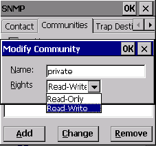
Name
The value assigned here is the name assigned by the network administrator to the set
of devices to which this managed node belongs.
Rights
This menu allows you to specify access, that is, ‘Read-Only’ or ‘Read-Write’
5.12.2.2 Modifying A Community Setting
To modify an existing community:
• Highlight the community you want to alter.
• Choose the Change button.
A Modify Community dialog box is displayed, listing the community you
highlighted.
•Edit the Name and/or Rights, and press [ENTER] to save your changes.
5.12.2.3 Removing An Existing Community
To remove an item:
• Highlight the community you want to remove in the Communities tab and
then choose the Remove button.
A Delete Confirmation screen is displayed.
• To remove a community, choose the Yes button, or
If you decide not to remove the community, choose the No button.
WORKABOUT PRO G2 Hand-Held With Windows Embedded CE 5.0 User Manual 209
Chapter 5: Configuration
Trap Destination Tab
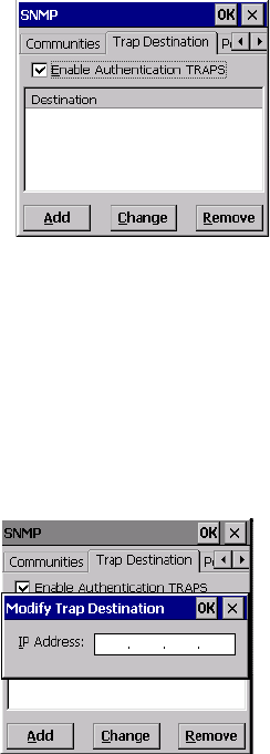
5.12.3 Trap Destination Tab
A trap is an unsolicited report sent to SNMP Managers by the SNMP Agent running
on the managed node. This option allows you to define where the report will be sent.
5.12.3.1 Enabling Authentication TRAPS
Enabling Enable Authentication TRAPS allows authorization traps to be sent when
a failure is detected (e.g., an SNMP message received with a bad community name).
5.12.3.2 Adding A Destination
To add a new destination:
• Choose the Add button.
• Type a destination IP address in the text box provided, and press [ENTER].
5.12.3.3 Changing A Destination
To change an existing trap destination:
• Highlight the destination you want to alter in the Trap Destination tab, and
then choose the Change button.
Chapter 5: Configuration
Permitted Hosts Tab
210 WORKABOUT PRO G2 Hand-Held With Windows Embedded CE 5.0 User Manual
A dialog box like the one displayed when you add a destination is displayed.
• Make the changes to the destination, and press [ENTER] to save the
changes.
5.12.3.4 Removing A Trap Destination
To remove a trap destination:
•In the Trap Destination tab, highlight the destination you want to delete.
• Choose the Remove button.
A Delete Confirmation screen is displayed.
• To remove a destination, choose the Yes button, or
If you decide not to remove the destination, choose the No button.
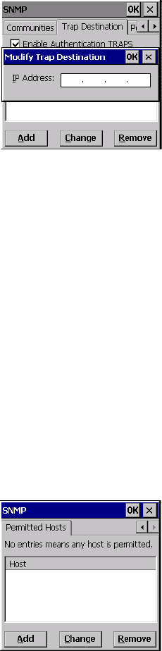
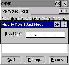
5.12.4 Permitted Hosts Tab
For security reasons, the Network Administrator may want to restrict SNMP-node
access to a known sub-set of SNMP Managers. This tab lists the IP addresses of all
the SNMP Managers which are allowed to monitor and manage this device. If no
entries are listed, the device will accept SNMP queries from any host.
WORKABOUT PRO G2 Hand-Held With Windows Embedded CE 5.0 User Manual 211
Chapter 5: Configuration
Permitted Hosts Tab
5.12.4.1 Adding A Host
To add a new host:
• Highlight the Add button, and press [ENTER].
• Type a new host IP address in the text box provided, and press [ENTER].
5.12.4.2 Changing A Host
To change an existing host IP address:
• Highlight the IP address you want to alter in the Permitted Hosts tab, and
then choose the Change button.
A dialog box like the one displayed when you add a host is displayed.
• Make the necessary changes, and press [ENTER].

WORKABOUT PRO Hand-Held Computer With Windows Mobile 5.0 User Manual 213
PERIPHERAL DEVICES & ACCESSORIES 6
6.1 Carrying Accessories.............................215
6.1.1 Attaching The Hand Strap.......................215
6.1.2 Attaching The Pistol Grip.......................217
6.1.3 Protective Carrying Case........................218
6.1.3.1 Using The Swivel Belt Loop With The Carrying Case.....218
6.1.4 Soft Shell Holster ...........................220
6.2 The Batteries.................................221
6.3 Chargers And Docking Stations.......................221
6.3.1 Installation–Chargers And Docking Stations.............221
6.3.2 Power Consumption Considerations..................221
6.3.3 Operator Controls...........................222
6.3.4 Important Charger Safety Instructions.................222
6.4 Desktop Docking Station...........................223
6.4.1 Charging A Battery Installed In The WORKABOUT PRO G2. . . . 224
6.4.2 Charging A Spare Battery.......................225
6.4.3 Battery Charge Duration........................225
6.4.4 Charger LED Indicators........................225
6.4.5 Troubleshooting The Charging Operation Of The Dock .......225
6.4.6 Desktop Docking Station Ports....................226
6.4.7 Linking A WORKABOUT PRO G2 To A PC............226
6.4.7.1 Using Microsoft ActiveSync To Work With Files.......227
6.4.8 Linking A WORKABOUT PRO G2 To An Ethernet Network . . . . 227
6.4.8.1 Network Access.........................227
6.4.9 Troubleshooting The Docking Station Operations. . .........228
6.5 Single Battery Charger–Model #WA3001-G1 . ...............228
6.5.1 Inserting A Battery In The Single Battery Charger..........228
6.5.2 Battery Charge Duration........................228
6.5.3 Charge Indicators–The LED......................229
Chapter 6: Peripheral Devices & Accessories
214 WORKABOUT PRO Hand-Held Computer With Windows Mobile 5.0 User Manual
6.6 Quad Battery Charger–Model #WA3004-G1.................229
6.6.1 Charging Batteries...........................230
6.6.2 Battery Charge Duration........................230
6.6.3 Charge Indicators–The LEDs......................230
6.6.4 Troubleshooting . . . .........................230
6.6.4.1 Excessive Charge Duration..................230
6.6.4.2 Indicator Flashing Red.....................230
6.6.4.3 Power LED Does Not Light Up................231
6.6.4.4 Indicator Does Not Light When Battery Installed.......231
6.7 Quad Docking Station–Model #WA4004-G1.................232
6.7.1 Quad Docking Station Setup......................232
6.7.2 Quad Indicators.............................233
6.7.3 Inserting A WORKABOUT In The Quad Docking Station......233
6.7.4 Network Access . . . .........................233
6.7.4.1 Network Addressing......................233
6.7.5 Battery Charging–LED Behaviour...................234
6.7.6 Troubleshooting . . . .........................234
6.7.6.1 Network Link Unsuccessful..................234
6.7.6.2 Hand-Held LED Does Not Light When Docked.......234
6.8 The Vehicle Cradle..............................235
6.8.1 Vehicle Cradle Mounting Recommendations . ............235
6.8.1.1 Mounting Template......................236
6.8.2 Wiring Guidelines ...........................236
6.8.3 Using The Vehicle Cradle .......................236
6.8.4 Maintaining The Vehicle Cradle....................236
6.8.5 Powered Cradle Installation In High Voltage Vehicles.........237
6.8.6 Powered Vehicle Cradle Installation..................237
6.8.6.1 Wiring Vehicle Power To The Cradle.............238
6.8.7 The Port Replicator...........................238
6.9 Bluetooth Peripherals.............................239

WORKABOUT PRO Hand-Held Computer With Windows Mobile 5.0 User Manual 215
Chapter 6: Peripheral Devices & Accessories
Carrying Accessories
6.1 Carrying Accessories
There are a variety of carrying accessories to help the operator work safely and
comfortably with the WORKABOUT PRO G2.
Table 6.1 Carrying Accessories
Important: Do not use adhesives such as Loctite to secure screws on
carrying accessories. These chemicals may damage the
plastic casing.
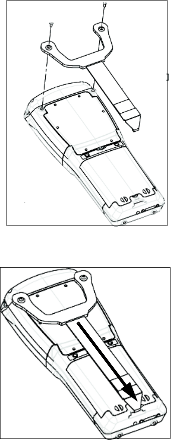
6.1.1 Attaching The Hand Strap
The hand strap can be attached to the back of the WORKABOUT PRO G2 to
provide a secure means for operators to carry the hand-held.
The hand strap is attached to the back of unit using two Phillips head screws
provided with this accessory.
Carrying Accessory Model Number
Hand Strap WA6025 for WORKABOUT PRO C G2
WA6125 for WORKABOUT PRO S G2
Pistol Grip WA6001-G1
Pistol Grip for SX5393 Imager WA6002-G1
Protective Vinyl Case WA6091 for WORKABOUT PRO C G2
WA6190 for WORKABOUT PRO S G2
Soft Shell Holster WA6050
Chapter 6: Peripheral Devices & Accessories
Attaching The Hand Strap
216 WORKABOUT PRO Hand-Held Computer With Windows Mobile 5.0 User Manual
• Use a Phillips screwdriver to attach the strap to the two threaded inserts on
the back of the WORKABOUT PRO G2, near the top of the unit
• Stretch the hand strap toward the base of the WORKABOUT PRO G2, and
hook the bottom of the strap into the slot near the base of the battery pack.
WORKABOUT PRO Hand-Held Computer With Windows Mobile 5.0 User Manual 217
Chapter 6: Peripheral Devices & Accessories
Attaching The Pistol Grip
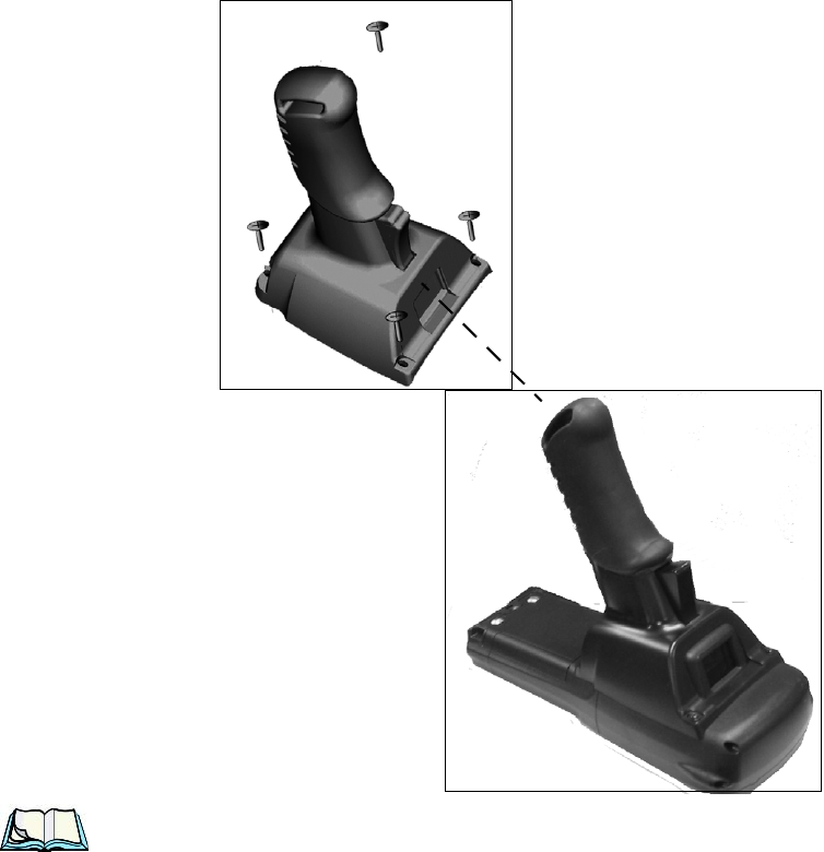
6.1.2 Attaching The Pistol Grip
The pistol grip is attached to the four threaded inserts on the back of the WORK-
ABOUT PRO G2. Four Phillips head screws are provided with this accessory.
Note: Prior to installation, make sure the trigger mechanism is securely
snapped into the pistol grip body and that the trigger operates properly.
• Position the pistol grip so that it fits snugly over the back of the unit and the
holes in the pistol grip are aligned with the threaded inserts on the back of
the WORKABOUT PRO G2.
Chapter 6: Peripheral Devices & Accessories
Protective Carrying Case
218 WORKABOUT PRO Hand-Held Computer With Windows Mobile 5.0 User Manual
• Tighten the screws to a torque of 3 lbs-in (3kgf-cm) to secure the pistol grip
in place.
6.1.3 Protective Carrying Case
A carrying case is available for WORKABOUT PRO G2s to shield the unit from
damage. It is equipped with a soft plastic window to protect the unit display and
keyboard. A variety of cases are available, depending on the type of end-cap
attached to your unit.
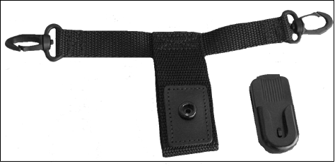
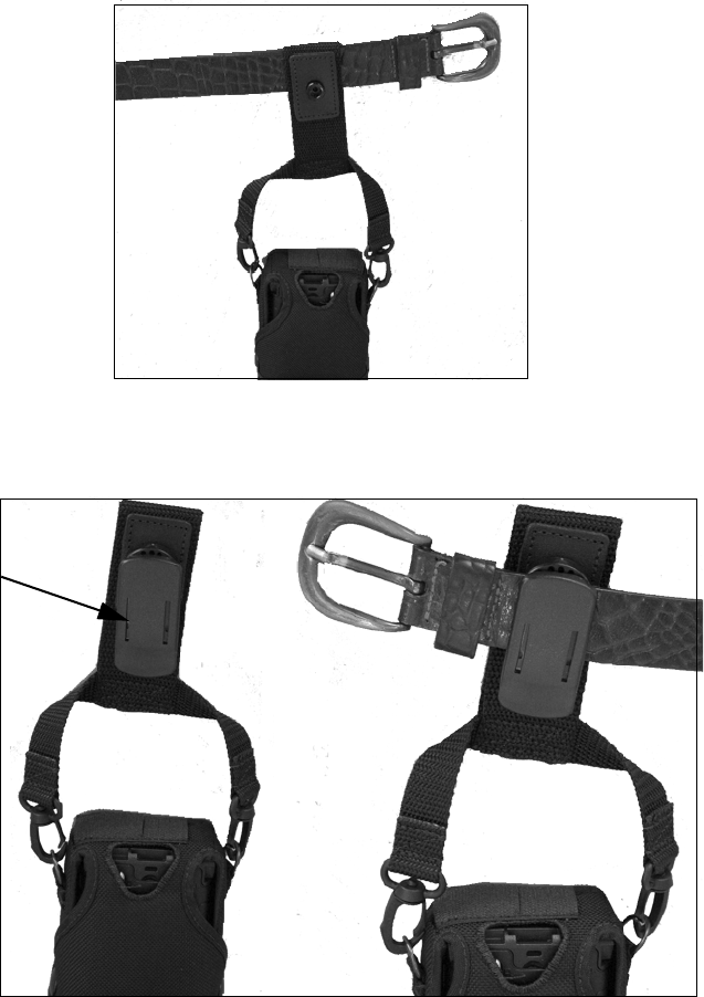
6.1.3.1 Using The Swivel Belt Loop With The Carrying Case
The WORKABOUT PRO G2 carrying case is equipped with two rings onto which
you can attach a swivel belt loop so that you can hang the unit from your belt. If you
prefer, you can also attach a belt clip to this accessory so that you can clamp the unit
onto your waistband or belt. (rather than slide your belt through the belt loop).
Figure 6.1 Belt Loop And Belt Clip
• Clip the two hooks on the belt strap to the bottom of the carrying case.
WORKABOUT PRO Hand-Held Computer With Windows Mobile 5.0 User Manual 219
Chapter 6: Peripheral Devices & Accessories
Protective Carrying Case
• Slide your belt through the belt loop.
Figure 6.2 Attaching The Belt Loop
Alternatively, you can attach a plastic clip to the swivel belt loop and clip it to your
waistband or belt.
Figure 6.3 Belt Clip
Belt Clip
Chapter 6: Peripheral Devices & Accessories
Soft Shell Holster
220 WORKABOUT PRO Hand-Held Computer With Windows Mobile 5.0 User Manual
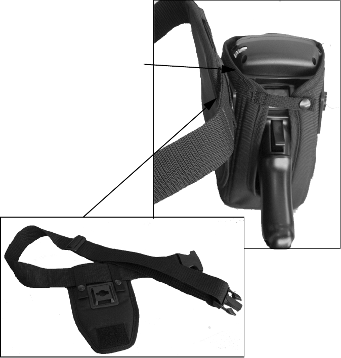
6.1.4 Soft Shell Holster
A soft shell holster with removable belt and swivel holster pad can be used to hang a
WORKABOUT PRO G2 with a pistol grip from you waist
Figure 6.4 Soft Shell Holster
• Insert the belt in the swivel holster pad.
• Attach the pad on either the left or right side of the holster case, depending
on whether you are left- or right-handed.
• Fasten the belt comfortably around your waist. Slide the adjustable ring on
the belt to tighten the holster in place.
Swivel Holster Pad and
Removable Belt
Soft Shell Holster

WORKABOUT PRO Hand-Held Computer With Windows Mobile 5.0 User Manual 221
Chapter 6: Peripheral Devices & Accessories
The Batteries
6.2 The Batteries
The WORKABOUT PRO G2 will operate with a High-Capacity Lithium Ion
battery pack, a Super High-Capacity Lithium Ion battery pack.
In addition to the main battery, the hand-held is equipped with a rechargable coin
battery–a Maxell ML2032.
6.3 Chargers And Docking Stations
Important: Keep in mind when ordering a charger or docking station, you
must also order the appropriate power cord separately.
Psion Teklogix offers a variety of chargers and docking stations for the
WORKABOUT PRO G2. These include:
• Single Battery Charger–Model No. WA3001-G1
• Quad Battery Charger–Model No. WA3004-G1
• Desktop Docking Station–Model No. WA4003-G2
• Quad Docking Station–Model No. WA4004-G1
6.3.1 Installation–Chargers And Docking Stations
When installing a charger or docking station, consider the following guidelines.
• Keep chargers and docking stations away from excessive dirt, dust and
contaminants.
• Chargers will not charge batteries outside an ambient temperature range
of 0° C to 45 °C (32° F to 113° F). It is recommended that the charger or
docking station be operated at room temperature–between 18° C and 25° C
(64° F to 77° F) for maximum performance.
After unpacking your unit:
• Visually inspect the charger for possible damage.
• Install the IEC power cord and apply power.
6.3.2 Power Consumption Considerations
Check to ensure the mains circuit supplying chargers and/or docking stations is
adequate for the load, especially if several chargers and docking stations are being
powered from the same circuit.
• Quad charger–can consume up to 2A @ 120VAC or 1A @ 240VAC.

Chapter 6: Peripheral Devices & Accessories
Operator Controls
222 WORKABOUT PRO Hand-Held Computer With Windows Mobile 5.0 User Manual
• Quad docking station–can consume up to 3A @ 120VAC or 1.5A @
240VAC.
6.3.3 Operator Controls
WORKABOUT PRO G2 docking stations and chargers have no operator controls or
power switches.
6.3.4 Important Charger Safety Instructions
•SAVE THESE INSTRUCTIONS–This manual contains important safety and
operating instructions for battery charger s.
• Before using the battery charger, read all instructions and cautionary
markings on (1) battery charger, (2) battery, and (3) product using battery.
• The mains power cord shall comply with national safety regulations of the country
where the equipment is to be sold.
• Use of an attachment not recommended or sold by the battery charger
manufacturer may result in fire, electric shock, or personal injury.
• To reduce risk of damage to the electric plug and cord when unplugging the
charger, pull the plug rather than the cord.
• Make sure the cord is positioned so that it is not stepped on, tripped over,
or otherwise subjected to damage or stress.
• Do not operate the charger with a damaged cord or plug.
Replace immediately.
• Do not operate the charger if it has received a sharp blow, been dropped, or other-
wise damaged in any way; it should be inspected by qualified service personnel.
• Do not disassemble the charger; it should be repaired by qualified service person-
nel. Incorrect reassembly may result in electric shock or fire.
• To reduce risk of electric shock, unplug the charger from the outlet before
attempting any maintenance or cleaning.
• An extension cord should not be used unless absolutely necessary. Use of an
improper extension cord could result in fire or electric shock.
If an extension cord must be used, make sure:
• The plug pins on the extension cord are the same number, size,
and shape as those on the charger.
• The extension cord is properly wired and in good electrical
condition and that the wire size is larger than 16 AWG.
• Do not expose the charger to rain or snow.
• Do not place batteries in the charger if they are cold from extended
exposure to a freezer or outside temperatures below 10°C (50°F). Allow them to
warm up to room temperature for at least two hours.
WORKABOUT PRO Hand-Held Computer With Windows Mobile 5.0 User Manual 223
Chapter 6: Peripheral Devices & Accessories
Desktop Docking Station
• Do not use the charger if, after an overnight charge, any of the batteries feel warmer
than the charger housing. The charger should be inspected by
qualified service personnel.
• Do not use the charger if any of the batteries or the charger get more than luke-
warm. The equipment should be inspected by qualified personnel.
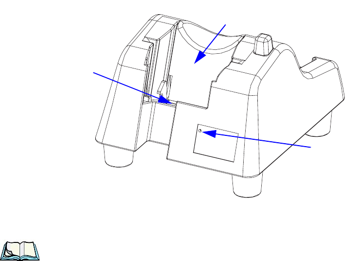
6.4 Desktop Docking Station
The WORKABOUT PRO G2 can be inserted in a desktop docking station, model
number WA4003-G2.
Figure 6.5 Desktop Docking Station
Note: The desktop docking charger is shipped with its own user manual. It is
critical that it be reviewed for additional information and updates.
WORKABOUT PRO G2
Charge Well
LED
Docking Station
Connector Pins
(Indicates charge status of
a spare battery inserted
in the rear charge well of
the docking station.)
Chapter 6: Peripheral Devices & Accessories
Charging A Battery Installed In The WORKABOUT PRO G2
224 WORKABOUT PRO Hand-Held Computer With Windows Mobile 5.0 User Manual
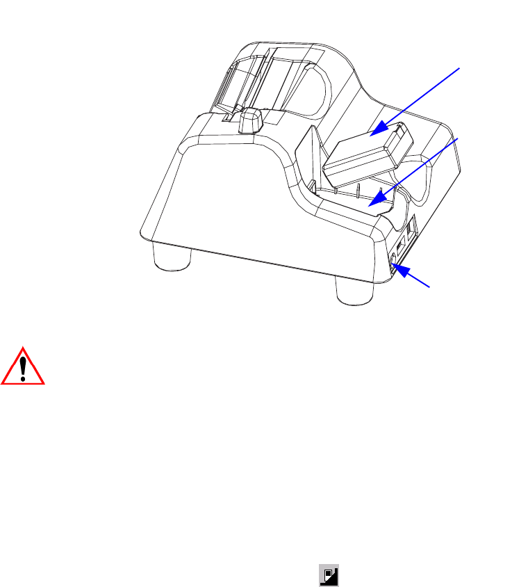
The desktop docking station is designed to charge the battery installed in the
WORKABOUT PRO G2 along with a spare battery pack.
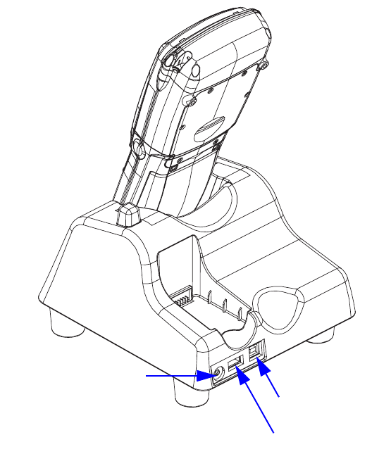
Figure 6.6 Back Of Desktop Docking Station
Important: This docking station can only be used to charge Psion Teklogix
approved Lithium-Ion batteries–specifically model numbers
WA3000-G1 and WA3006.
6.4.1 Charging A Battery Installed In The WORKABOUT PRO G2
• Insert the DC power cable to the DC IN socket on the desktop docking
station. Plug the pronged end of the cable into an AC outlet.
• Slide the hand-held into the docking station, making certain that the LIF
(Low Insertion Force) port on base of the WORKABOUT is securely
seated on the docking station connector pins. An icon is displayed briefly in
the navigation bar at the top of the hand-held screen indicating that the unit
is properly installed in the station–. This icon is only displayed when
the unit is switched on.
The LED on the WORKABOUT PRO G2 lights up indicating that the unit has
external power and battery charging will begin. It is safe to leave the unit in the
desktop docking station while it is not in use–the battery will not be overcharged.
Spare Battery
Charge Well
DC IN Socket
Spare Battery

WORKABOUT PRO Hand-Held Computer With Windows Mobile 5.0 User Manual 225
Chapter 6: Peripheral Devices & Accessories
Charging A Spare Battery
6.4.2 Charging A Spare Battery
• Insert the battery in the spare battery charge well at the back of the docking
station, aligning the contacts on the battery with the contacts in the spare
battery charge well.
6.4.3 Battery Charge Duration
A fully discharged battery can take up to 5 hours to charge. The desktop docking
station stops applying power to the battery when it is fully charged–there is no risk
of overcharge if the battery remains in the charge well.
6.4.4 Charger LED Indicators
The desktop docking station is equipped with a single dual-coloured LED indicator
in the lower-right corner of the front panel.
Table 6.2 Desktop Battery Charger LED Behaviour
Note: Battery charging continues whether the hand-held is switched on or off.
6.4.5 Troubleshooting The Charging Operation Of The Dock
The quad battery charger troubleshooting section beginning on page 230 also
applies to the charging behaviour of the desktop docking station.
LED Behaviour Charge Status
Off No battery detected in the slot.
Solid Green Charge in progress.
Fast Flashing Green Battery charged to less than 80% of capac-
ity.
Slow Flashing Green Battery charged to greater than 80% of
capacity.
Solid Red Battery temperature outside of charge
range–
0° C to 50 °C.
Flashing Red Battery is not charging. Battery fault.
Chapter 6: Peripheral Devices & Accessories
Desktop Docking Station Ports
226 WORKABOUT PRO Hand-Held Computer With Windows Mobile 5.0 User Manual
6.4.6 Desktop Docking Station Ports
Figure 6.7 Back of Desktop Docking Station
The desktop docking station is equipped with two USB ports–a Host USB port to
connect peripherals such as a printer, keyboard, etc. and a Client USB to connect the
docking station to a PC.
6.4.7 Linking A WORKABOUT PRO G2 To A PC
The desktop docking station can be connected to a PC so that you can exchange files
in the same way that you would between PC drives. A USB cable is included with
your docking station.
DC IN Socket
Host USB Port
Client USB Port
WORKABOUT PRO Hand-Held Computer With Windows Mobile 5.0 User Manual 227
Chapter 6: Peripheral Devices & Accessories
Linking A WORKABOUT PRO G2 To An Ethernet Network
To link the WORKABOUT PRO G2 to a PC:
• Insert the hand-held in the desktop docking station.
• Insert the USB cable into the docking station Client USB connector. Attach
the other end of the cable to a USB port on the PC.
You’ll need to install connectivity software on your PC before you can pass
information between the hand-held and the PC.
6.4.7.1 Using Microsoft ActiveSync To Work With Files
ActiveSync®–Microsoft PC connectivity software–can be used to connect the
WORKABOUT PRO G2 to PCs running this software. You’ll be able to:
• View WORKABOUT PRO G2 files from Windows Explorer.
• Drag and drop files between the WORKABOUT PRO G2 and the PC in the
same way that you would between PC drives.
• Back up WORKABOUT PRO G2 files to the PC, then restore them from
the PC to the hand-held again, if needed, and so on.
You can use the Getting Started CD included with your WORKABOUT PRO G2 to
install ActiveSync.
6.4.8 Linking A WORKABOUT PRO G2 To An Ethernet Network
An USB-Ethernet adaptor cable – model number WA4010-G1 – is used to connect
the WORKABOUT PRO G2 to an Ethernet network through a desktop docking
station.
• Insert the adaptor’s USB connector into the Host USB port on the desktop
docking station.
• Connect your network Ethernet cable to the Ethernet port on the adaptor
cable.
6.4.8.1 Network Access
The hand-held unit automatically detects insertion into the desktop dock and loads
the appropriate drivers to communicate with the USB-Ethernet converters.
Network Addressing
The host application uses standard TCP/IP protocol to name, locate and
communicate with a specific WORKABOUT PRO G2 on the network.

Chapter 6: Peripheral Devices & Accessories
Troubleshooting The Docking Station Operations
228 WORKABOUT PRO Hand-Held Computer With Windows Mobile 5.0 User Manual
If a link is established between a WORKABOUT PRO G2 and a host, the
application on the host and on the hand-held must have a recovery mechanism in the
event that the WORKABOUT PRO G2 is removed from the dock, interrupting the
link.
6.4.9 Troubleshooting The Docking Station Operations
The indicators, applications and drivers required to use and monitor the desktop
docking station as a dock (as opposed to a charger) are installed on the
WORKABOUT PRO G2–no applications are present on the docking station itself.
6.5 Single Battery Charger–Model #WA3001-G1
Figure 6.8 Single Battery Charger
The single battery charger is designed to charge a single battery. It has a DC IN
socket and is equipped with one LED that indicates the status of the charge process.
6.5.1 Inserting A Battery In The Single Battery Charger
• Insert the DC power plug into the charger. Plug the pronged end of the
power cable into an AC outlet.
• Install the battery, aligning the contacts on the battery with the contacts in
the battery charge well.
6.5.2 Battery Charge Duration
It can take up to 4 hours to fully charge a battery. The single battery charger stops
applying power to the battery when it is fully charged–there is no risk of overcharge
if the battery remains in the charge well. The 75% charge indicator is handy if you
need a quick recharge–a quick charge often takes less than one hour.
WORKABOUT PRO Hand-Held Computer With Windows Mobile 5.0 User Manual 229
Chapter 6: Peripheral Devices & Accessories
Charge Indicators–The LED
6.5.3 Charge Indicators–The LED
The LED on the top of the charger indicates battery charge progress.
Table 6.3 Single Battery LED Behaviour
Note: Battery charging continues whether the hand-held is switched on or off.
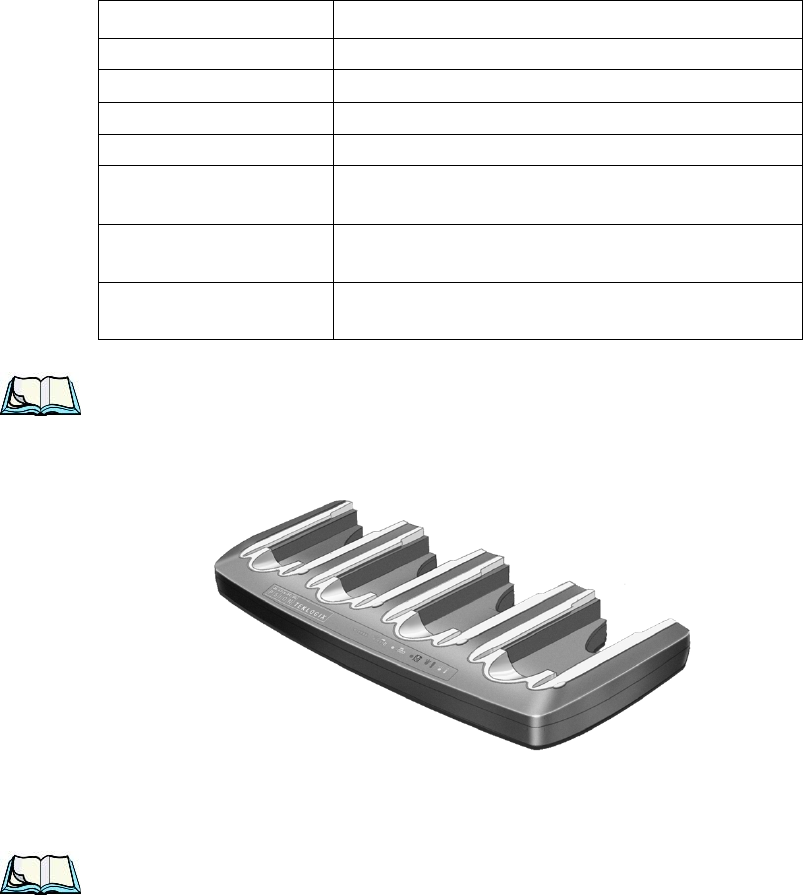
6.6 Quad Battery Charger–Model #WA3004-G1
Table 6.4 Quad Battery Charger
The quad battery charger is designed to charge up to four Lithium Ion batteries at
one time.
Note: The gang charger is shipped with a user manual. It is critical that this
manual be reviewed for additional information and updates.
LED Behaviour Charge Status
Off No battery detected in the charge well.
Solid green Battery is fully charged.
Fast flashing green Battery is charged to 75% of capacity.
Slow flashing green Charge in progress.
Solid red Battery is outside ambient temperature range of
0° C to 45 °C (32° F to 113° F).
Flashing red Charge alarm indicating a charging circuit problem.
Refer to “Troubleshooting” on page 230 for details.
Flashing red then green
in a 3 second cycle Power up test sequence.
Chapter 6: Peripheral Devices & Accessories
Charging Batteries
230 WORKABOUT PRO Hand-Held Computer With Windows Mobile 5.0 User Manual
6.6.1 Charging Batteries
• Slide the battery into a charge well, aligning the contacts on the battery with
the contacts in the charge well.
6.6.2 Battery Charge Duration
A fully discharged battery can take up to 4 hours to charge. The quad battery charger
stops applying power to the battery when it is fully charged–there is no risk of
overcharge if the battery remains in the charge well. The 75% charge indicator is
handy if you need a quick recharge–a quick charge often takes less than one hour.
6.6.3 Charge Indicators–The LEDs
Each battery charge well is equipped with an LED to indicate the charge status of
the battery. When a battery is inserted in the charger, the colour and behaviour of the
LED associated with the charge well in use indicates the status of the charge. Refer
to Table 6.3 on page 229 for details.
6.6.4 Troubleshooting
6.6.4.1 Excessive Charge Duration
The charger is equipped with a recalibration function–a function that fully
discharges and then fully recharges the battery. This process is necessary to
recalibrate the battery capacity gauge internal to the battery. The charger attempts
recalibration when:
• the battery capacity is at less than 30%, and
• the battery has undergone more than 40 partial charge cycles since the last
full discharge.
The recalibration function extends the charge time by up to 2 hours.
6.6.4.2 Indicator Flashing Red
If the indicator flashes red:
• Remove all batteries and disconnect the mains power cable.
• Wait at least 20 seconds, and then plug the cable in again.
If any of the charge well LEDs continue to flash red, the charger is defective and
requires service. If all indicators are flashing red, there is a power supply problem
and the charger requires service.
WORKABOUT PRO Hand-Held Computer With Windows Mobile 5.0 User Manual 231
Chapter 6: Peripheral Devices & Accessories
Troubleshooting
6.6.4.3 Power LED Does Not Light Up
• Remove all batteries, and unplug the charger.
• Connect another device to the mains outlet to ensure there is power.
• Remove the IEC mains power cable from the charger, and check it for damage.
• Reconnect the mains cable in the charger and mains outlet.
If the power LED still does not light up:
• Unplug the mains cable, and check the fuse at the rear of the charger.
If the fuse appears to be intact, the charger requires service.
6.6.4.4 Indicator Does Not Light When Battery Installed
• Remove the battery, and clean the contacts on the battery and the
charge well.
• Reinstall the battery, and check that it is fully seated in the charger well.
• Inspect the charge well contacts for damage (are they bent, flattened,
twisted or broken).
• Try inserting a battery that you know to be working in the charger well.
• Reconnect the mains power cable, and check that the charger well indicator
flashes at powerup.
Chapter 6: Peripheral Devices & Accessories
Quad Docking Station–Model #WA4004-G1
232 WORKABOUT PRO Hand-Held Computer With Windows Mobile 5.0 User Manual
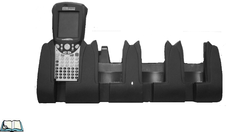
6.7 Quad Docking Station–Model #WA4004-G1
Figure 6.9 Quad Docking Station
Note: The quad docking station is shipped with a docking manual. It is critical
that this manual be reviewed for additional information and updates.
The quad docking station permits each of four docked WORKABOUT PRO G2s to
communicate with a 10/100 BaseT Ethernet network at greater than 2Mbps. It also
provides sufficient power to operate and fast charge the batteries in the units.
6.7.1 Quad Docking Station Setup
After unpacking the unit:
• Visually inspect the unit for any damage.
• Install the IEC power cord and apply power.
A green indicator in the lower-right corner of the front panel lights up to indicate
that power is present.
• Attach a CAT5 RJ45 network patch cable (supplied) between your network
and the RJ45 jack on the rear of the dock.
A green LED is illuminated next to the RJ45 connector when a valid network link is
established.

WORKABOUT PRO Hand-Held Computer With Windows Mobile 5.0 User Manual 233
Chapter 6: Peripheral Devices & Accessories
Quad Indicators
A user application must be loaded onto each WORKABOUT PRO G2 that utilizes
the quad dock for communication. When the network is connected and this
application is loaded, the quad dock is ready for use.
6.7.2 Quad Indicators
The quad dock is equipped with a power indicator LED and RJ45 link and traffic
indicator LEDs. When a valid network link is established, a green LED is
illuminated next to the RJ45 connector.
6.7.3 Inserting A WORKABOUT In The Quad Docking Station
• Slide the WORKABOUT PRO G2 into the cradle portion of the quad dock
until lightly latched.
The hand-held detects that it is in a quad dock and momentarily displays the appropriate
icon in the navigation bar at the top of the screen–. The LED on the hand-held unit
lights up to show it has external power and may start charging the battery.
Interaction with the WORKABOUT PRO G2 while in the quad dock is a function
of the user application software used to communicate with the host network.
6.7.4 Network Access
The quad docking station has one 10/100 Ethernet port. You can insert up to four
hand-held units. The hand-helds are connected to an internal USB hub. The hand-
held unit automatically detects insertion into a quad docking station and loads the
appropriate drivers to communicate with the USB/Ethernet converters.
6.7.4.1 Network Addressing
Although the USB converters have fixed Ethernet MAC addresses, there is
generally no correlation between these addresses and a specific hand-held. The host
application uses standard TCP/IP protocol to name, locate and communicate with a
specific WORKABOUT PRO G2 on the network.
If a link is established between a WORKABOUT PRO G2 and a host, the
application on the host and on the hand-held must have a recovery mechanism in the
event that the WORKABOUT PRO G2 is removed from the dock and the link is
interrupted.
Chapter 6: Peripheral Devices & Accessories
Battery Charging–LED Behaviour
234 WORKABOUT PRO Hand-Held Computer With Windows Mobile 5.0 User Manual
6.7.5 Battery Charging–LED Behaviour
The quad docking station supplies DC power to enable the WORKABOUT PRO
G2 internal fast charger. Charge status is displayed on the hand-held LED–the LED
turns red while the battery is being charged and turns green once the charge is
complete. If the battery is fully charged when the unit is inserted in the docking
station, the LED flashes red for less than a second and then turns green. Battery
charging continues whether the WORKABOUT PRO G2 is switched on or off.
It can take up to 5 hours to fully charge the internal battery.
6.7.6 Troubleshooting
The indicators, applications and drivers required to use and monitor the docking
station are installed on the WORKABOUT PRO G2–no indicators or applications
are present on the docking station itself.
6.7.6.1 Network Link Unsuccessful
If a network link fails, the WORKABOUT PRO G2 application alerts the operator
that the link was unsuccessful.
6.7.6.2 Hand-Held LED Does Not Light When Docked
• Check that the quad docking station has power–is the Power LED on the
docking station illuminated?
• Try inserting the WORKABOUT PRO G2 in another well in the quad dock.
• Check for dirt or contamination on the docking contacts at the bottom of the
WORKABOUT PRO G2. Wipe the contacts with a damp cloth if necessary.
• Check the pogo pins inside the dock cradle for dirt. Gently wipe with a
damp cloth if they appear to be dirty or discoloured.
• Check that the pogo pins are not bent or damaged.
• Remove and reinsert the WORKABOUT PRO G2 in the cradle, and check
that the latch is holding the unit in place (the pogo pins must be compressed
for proper contact).
• Make certain that the battery installed in the WORKABOUT PRO G2 is
not defective.

WORKABOUT PRO Hand-Held Computer With Windows Mobile 5.0 User Manual 235
Chapter 6: Peripheral Devices & Accessories
The Vehicle Cradle
6.8 The Vehicle Cradle
The vehicle cradle is a highly ruggedized, single station dock. Although it provides
quick insertion and removal, the cradle holds the WORKABOUT PRO G2 securely
even when operated in high vibration environments.
Depending on the type of hand-held unit you are use, you can choose from the
following powered vehicle cradle models:
• Vehicle Cradle for WORKABOUT PRO C G2 – WA1010-G1
• Vehicle Cradle for WORKABOUT PRO S G2 – WA1110-G1
A port replicator option is available for powered vehicle cradles. Refer to “The Port
Replicator” on page 238 for details.
6.8.1 Vehicle Cradle Mounting Recommendations
Warning: Before mounting a vehicle cradle in a vehicle, there are a number
of operator safety issues that require careful attention. An improp-
erly mounted cradle may result in one or more of the following:
operator injury, operator visibility obstruction, operator distraction
and/or poor ease of egress for the operator. Psion Teklogix strongly
recommends that you seek professional mounting advice from the
vehicle manufacturer.
Cable routing within a vehicle cab also requires careful consider-
ation, especially for separately tethered scanners and other devices
with loose cables. If you are unable to obtain suitable advice,
contact Psion Teklogix for assistance (see Appendix A: Support Ser-
vices And Worldwide Offices). Note also that for better protection,
the equipment should be mounted inside the vehicle roll cage.
Pedestal mounts are recommended for all fixed mount locations because they offer
optimal operator access. In addition, for safety reasons, only pedestal mounts with
fully locking joints should be used in vehicles. Always adjust the pedestal for the
optimum viewing angle, and securely tighten the hex and wing screws.
The most effective way to mount the vehicle cradle is to use the four #8-32 threaded inserts
on the rear of the unit. Bolts must not extend more than 10mm (3/8") into the cradle.
To accommodate the service loop of the connector cable, leave a 4" clearance at the
bottom of the cradle. Leave a 7" (minimum) clearance at the top of the cradle to
allow easy removal of the hand-held. Also remember to leave at least a 3" clearance
at the sides of the cradle to allow activation of the release knobs. Refer to the
detailed assembly instructions that are packaged with the cradle when selecting a
mounting location.
Chapter 6: Peripheral Devices & Accessories
Wiring Guidelines
236 WORKABOUT PRO Hand-Held Computer With Windows Mobile 5.0 User Manual
6.8.1.1 Mounting Template
The vehicle cradle is shipped with detailed mounting instructions including a drill template.
6.8.2 Wiring Guidelines
Before installing cables between the cradle and other devices, review the following:
• Ensure that drilling holes will not damage the vehicle or its wiring.
• Protect cable runs from pinching, overheating and physical damage.
• Use grommets to protect cables that pass through metal.
• Use plastic straps and tie-downs to secure cables and connectors in their
desired location, away from areas where they may get snagged or pulled.
• Keep cables away from heat sources, grease, battery acid and other
potential hazards.
• Keep cables away from control pedals and other moving parts that may
damage the cables or interfere with the operation of the vehicle.
6.8.3 Using The Vehicle Cradle
If your WORKABOUT PRO G2 is equipped with a shoulder strap or cover, these
accessories need to be removed before installing the unit in a vehicle cradle. There is
no need to remove handstraps, pistol grips or tethered devices from the unit.
• Slide the WORKABOUT PRO G2 into the cradle, and press firmly down-
ward until it locks into place. On a vehicle, it’s a good idea to pull up on the
WORKABOUT PRO G2 to be certain that it is secure.
• To remove the unit, press firmly on the RELEASE button on the front face
of the unit until it releases from it latch. The hand-held will be slightly
raised so that it can be removed.
6.8.4 Maintaining The Vehicle Cradle
Two latches in the cradle hold the WORKABOUT PRO G2 firmly in place.
Although these latches are designed for robustness and endurance, they will wear
over time and will no longer lock the hand-held securely in the cradle. For
replacement parts and instructions contact Psion Teklogix. Partial disassembly is
required.

WORKABOUT PRO Hand-Held Computer With Windows Mobile 5.0 User Manual 237
Chapter 6: Peripheral Devices & Accessories
Powered Cradle Installation In High Voltage Vehicles
6.8.5 Powered Cradle Installation In High Voltage Vehicles
Warning: Voltages exceeding 60VDC are considered hazardous. For powered
cradle installations on vehicles with batteries above this voltage,
ensure the powered cradle power connector is mounted in a dry
location on the vehicle, or that the connector is insulated with an
appropriate waterproof material after installation. The connector
must also be installed out of the vehicle operator’s reach. Exposing
an accessible power connector to water or other liquids could create
a hazardous situation resulting in serious injury or death.
Installation of powered cradles in vehicles that operate above 60VDC require
special consideration.
Due to the hazardous voltages present on these vehicles, it is necessary to ensure
that the powered cradle power supply cable connector is not accessible to the
vehicle operator, and does not get exposed to water or other liquids. This can be
accomplished in one of the following ways:
• Ensure the power connector is installed in a dry location on the vehicle,
away from the vehicle operator’s reach (perhaps under a vehicle dash or in a
sealed housing).
• Cover the power connector with a waterproof heat shrink material.
• Wrap the connector securely with a waterproof electrical tape in an area out
of the vehicle operators reach.
All other installation requirements outlined in this document should also be
followed for High Voltage vehicles to insure safe installation and operation of the
powered cradle.
6.8.6 Powered Vehicle Cradle Installation
The powered cradle is designed to allow the WORKABOUT PRO G2 to be
powered by a vehicle battery. The battery installed in the hand-held is also recharged
by the vehicle battery. This option accepts DC power sources ranging from 10 to
55V, with optional pre-regulator.
The vehicle cradle can be ordered with the powered cradle option installed.
Warning: Applying a voltage greater than that specified or reversing or
reversing polarity may result in permanent damage to the cradle
power option and will void the product warranty.
Chapter 6: Peripheral Devices & Accessories
The Port Replicator
238 WORKABOUT PRO Hand-Held Computer With Windows Mobile 5.0 User Manual
6.8.6.1 Wiring Vehicle Power To The Cradle
A 1.8 meter (6 foot) extension power cable (PN 13985) is supplied with your
powered vehicle cradle. This cable should be wired to a filtered, fused (maximum
10A) accessory supply on the vehicle. The power cradle draws no more than 8A
(less if the accessory supply is greater than 12V). Any additional wiring, connectors
or disconnects used should be rated for at least 10A.
The red lead of the power cable attaches to the positive vehicle supply. The black
lead connects to the negative supply–this should be connected to a proper terminal
block and not to the vehicle body. The power cradle is fully isolated and can be used
with both negative and positive chassis vehicles.
You may have the option of connecting power before or after the ‘key’ switch. It is
preferable to wire the power cradle after the key switch–that is, it cannot be turned
on without the key on. However, if the operator switches the key off repeatedly for
long periods during a shift, it may make more sense to wire the cradle before the
switch.
Keep in mind that the WORKABOUT PRO G2 will continue to operate with or
without vehicle power as long as its battery has sufficient charge.
If an unfused power source must be used, a fuse assembly (PN 19440) must be
added to the extension power cable (the fuse and instructions are supplied with the
cable). Use only a 10A slow blow UL approved fuse in the fuse assembly.
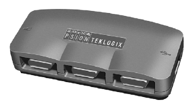
6.8.7 The Port Replicator
The port replicator (Model# WA4005-G1) is an optional accessory that allows
tethered devices as well as mounted peripherals (e.g., bar code printers or weigh
scales) to be attached to the vehicle cradle. The replicator can be used with or
without the cradle power option.
WORKABOUT PRO Hand-Held Computer With Windows Mobile 5.0 User Manual 239
Chapter 6: Peripheral Devices & Accessories
Bluetooth Peripherals
The functionality of the WORKABOUT PRO G2 tether port is replicated into RS-
232 serial interfaces by the port replicator. It provides the user with 3 DB9 serial
interfaces as well as one Type B USB port (for connecting a Host device).
6.9 Bluetooth Peripherals
The WORKABOUT PRO G2 is equipped with a Bluetooth radio, making it is
possible to communicate with a variety of Bluetooth peripherals, including
GSM/GPRS handsets, scanners, printers, and so on.
The range of the Bluetooth radio is limited to approximately 5 meters.
Psion Teklogix provides built-in support for the Bluetooth peripherals listed below.
• GSM/GPRS universal handset
• Bluetooth printer
Keep in mind that Bluetooth and IEEE 802.11g radios both operate in the 2.4GHz
band. Although the WORKABOUT PRO G2 includes features to minimize
interference, performance of the system will not be optimal if you use both radios
simultaneously. Typically, when both radios operate in the hand-held at the same
time, they cannot transmit simultaneously–this has a negative impact on overall
system throughput. To minimize the impact on the backbone 802.11g network,
Psion Teklogix recommends using Bluetooth peripherals that have low transaction
rates (such as printers and scanners).
Refer to “Bluetooth Setup” on page 111 for information about setting up your Blue-
tooth devices for communication. In addition, review the manual shipped with your
Bluetooth device to determine the method used to associate with the WORK-
ABOUT PRO G2 host.

WORKABOUT PRO G2 Hand-Held With Windows Embedded CE 5.0 User Manual 241
SPECIFICATIONS 7
7.1 WORKABOUT PRO G2...........................243
7.2 Radio Specifications.............................244
7.3 Scanner Specifications............................245
7.3.1 SE 1223HP, LR, ALR And SE 955HP Specifications . . . . . . . .245
7.3.1.1 SE 1223HP Decode Zone..................246
7.3.1.2 SE 1223LR Decode Zone..................246
7.3.1.3 SE 1223ALR Decode Zone . . . . . . . . . . . . . . . . .247
7.3.1.4 SE 955HP Decode Zone...................247
7.3.2 EV15 Imager Specifications.....................247
7.3.2.1 EV15 Imager Decode Zone . . . . . . . . . . . . . . . . .248
7.3.3 HHP5180 Imager...........................248
7.3.3.1 HHP5180 Imager Decode Zone . . . . . . . . . . . . . . .249
7.3.4 SX5393 Imager . . . . . . . . . . . . . . . . . . . . . . . . . . . .250
7.3.4.1 SX5393 Imager Decode Zone . . . . . . . . . . . . . . . .251

WORKABOUT PRO G2 Hand-Held With Windows Embedded CE 5.0 User Manual 243
Chapter 7: Specifications
WORKABOUT PRO G2
Note: Performance specifications are nominal & subject to change without
notice.
7.1 WORKABOUT PRO G2
Dimensions
• WORKABOUT PRO C G2: 223mm x 75/100mm
• WORKABOUT PRO S G2: 220mm x 75/100mm x 31/42mm
Weight (without battery)
• WORKABOUT PRO C G2: 450g
• WORKABOUT PRO S G2: 425g
Operating System
• Microsoft Windows Embedded CE 5.0
Drop Test
• Withstands 26 drops (on 12 edges, 8 corners, 6 faces) at 150cm to polished
concrete while powered on and configured with accessories such as CF
radio, scanner, pistol drip.
Water/Dust
• IP65, IEC 60529
Operating Temperature And Humidity
• 20 to 50° C (non-condensing); excluding display 1 to 50° C
• 5% to 91% RH non-condensing
Storage Temperature
• 40 to 60° C
Approvals
Safety: UL 60950-1, CSA C22.2 No. 60950-1-03, EN
60950-1, IEC 60825-1:1993+A1:1997+A2:2001
Class 2 CDRH 21 CFR 1040 Class II
EMC: FCC Part 15 Class B, EMC Directive Class B
Chapter 7: Specifications
Radio Specifications
244 WORKABOUT PRO G2 Hand-Held With Windows Embedded CE 5.0 User Manual
Laser: IEC 60825-1:1993+A1:1997+A2:2001 Class 2
CDRH 21 CFR 1040 Class II
7.2 Radio Specifications
Model RA2041: 802.11b/g Direct Sequence Spread Spectrum (DSSS)
Form factor Compact Flash Type I extended
Antenna port Two Hirose U.FL connectors for antenna diversity
Transmit Power 802.11g: 32mW maximum (+15 dBm)
802.11b: 80mW maximum (+19 dBm)
Frequency Range 2.400 - 2.4897 GHz
Channels FCC: 11
ETSI: 13
TELEC:13
RX Sensitivity -96dBm @ 1Mbps, -90dBm @ 11Mbps,
-94dBm @ 6Mbps, -75dBm @ 54Mbps
Data Rates 802.11g: 6, 9, 12, 18, 24, 36, 48, 54Mbps
802.11b: 1, 2, 5.5, 11 Mbps
Bluetooth Radio
Embedded (USB interface)
Bluetooth Version 1.2 compliant (features Adaptive Frequency
Hopping for better co-existence with 802.11 radio)
Chip Antenna 2dBi peak
Transmit Power -3dBm (0.5mW) minimum, +4dBm (2.5mW) max
Frequency Range 2.400 - 2.4835 GHz
RX Sensitivity -80dBm max
(BER<=0.1%)
Data Rate 732.2 kbps and 57.6 kbps asymmetric,
433.9 kbps symmetric

WORKABOUT PRO G2 Hand-Held With Windows Embedded CE 5.0 User Manual 245
Chapter 7: Specifications
Scanner Specifications
7.3 Scanner Specifications
7.3.1 SE 1223HP, LR, ALR And SE 955HP Specifications
Scan Engine SE 1223HP SE 1223LR SE 1223ALR SE 955HP
Scan Angle 42º ± 2º 23º ± 2º 13º ± 2º 47° ± 3° default /
35° ± 3° reduced
Scan Rate 35 (± 5) scans/sec
(bi-directional) 35 (± 5) scans/sec
(bi-directional) 35 (± 5) scans/sec
(bi-directional)
104 (± 12)
scans/sec
(bi-directional)
Scan Pattern Linear Linear Linear Linear
Wavelength 650nm 650nm 650nm 650nm
Input Voltage 5.0 VDC ± 10% 5.0 VDC ± 10% 5.0 VDC ± 10% 3.0-5.5 VDC ±
10%
Input Current 110 mA typical 115 mA typical 115 mA typical 65 mA typical
Standby Current 130 µA typical 70 µA max. 70 µA typical 8 µA max
Operating
Temperature -40ºC to 60ºC
-40ºF to 140ºF -30º to 55ºC
-22ºF to 131ºF -30°C to 55°C
-22ºF to 131ºF -20° to 60° C
-4° to 140° F
Print Contrast
Minimum 20%
absolute dark/light
reflectance mea-
sured at 650 nm
Minimum 40%
absolute dark/light
reflectance mea-
sured at 650 nm
Minimum 40%
absolute dark/light
reflectance mea-
sured at 650 nm
Minimum 25%
absolute dark/light
reflectance mea-
sured at 650 nm
Dimensions
1.93 cm max. H x
3.84 cm max. W x
3.51 cm max. D
0.76 in. max. H x
1.51 in. max. W x
1.38 in. max. D
1.93 cm max. H x
3.84 cm max. W x
3.51 cm max. D
0.76 in. max. H x
1.51 in. max. W x
1.38 in. max. D
1.93 cm max. H x
3.84 cm max. W x
3.51 cm max. D
0.76 in. max. H x
1.51 in. max. W x
1.38 in. max. D
1.21 cm H x 2.16
cm W x 1.55 cm
(max)
0.47 in. H x 0.85
in. W x 0.61 in. D
(max)
Symbologies
UPC/EAN, Code
128, Code 39,
Code 93, I 2 of 5,
Discrete 2 of 5,
Codabar, MSI
UCC/EAN 128,
TriOptic Code 39
UPC/EAN, Code
128, Code 39, Code
93, I 2 of 5, Dis-
crete 2 of 5,
Codabar, MSI
UCC/EAN 128,
TriOptic Code 39
UPC/EAN, Code
128, Code 39,
Code 93, I 2 of 5,
Discrete 2 of 5,
Codabar, MSI
UCC/EAN 128,
TriOptic Code 39
UPC/EAN, Code
128, Code 39,
Code 93, I 2 of 5,
Discrete 2 of 5,
Codabar, MSI
Plessey

Chapter 7: Specifications
SE 1223HP Decode Zone
246 WORKABOUT PRO G2 Hand-Held With Windows Embedded CE 5.0 User Manual
7.3.1.1 SE 1223HP Decode Zone
7.3.1.2 SE 1223LR Decode Zone
4,844 Lux to 86,112 Lux
Minimum
range Width of field Maximum
range Width of field
Mil Size Inches Inches Inches Inches
5 2.75 1.25 7 3
7.5 2.25 1 11 4
10 1.75 0.5 15.75 6
UPC 21229
15 2 1 25 10
20 2 1 30 12.5
40 3.75 56 23
55 5 66 25
4,844 Lux to 86,112 Lux
Minimum
range Width of field Maximum
range Width of field
Mil Size Inches Inches Inches Inches
10 11 2 24 5
15 7.5 1 39 8
20 7.5 1 48 10
40 10 2 90 19
55 10 2 120 24
70 reflective 48 200 40
100 reflective 60 240 48
High quality symbols in normal room light.

WORKABOUT PRO G2 Hand-Held With Windows Embedded CE 5.0 User Manual 247
Chapter 7: Specifications
SE 1223ALR Decode Zone
7.3.1.3 SE 1223ALR Decode Zone
7.3.1.4 SE 955HP Decode Zone
7.3.2 EV15 Imager Specifications
4,844 Lux to 86,112 Lux
Minimum
range Width of field Maximum
range Width of field
Mil Size Inches Inches Inches Inches
UPC 19 2 39 4
15 20 2 50 6
30 33 4 98 11
55 27 2 115 12
70 reflective 114 12 250 28
100 reflective 125 14 360 41
High quality symbols in normal room light.
Decode Zone Typical
4 mil 1.0 in. - 5.5 in. / 2.54 cm - 13.97 cm
5 mil 1.25 in. - 8 in. / 3.18 cm - 20.32 cm
7.5 mil 1.5 in. - 13.25 in. / 3.81 cm - 33.66 cm
10 mil 1.5 in. - 17.5 in. / 3.81 cm - 44.45 cm
UPC 100% 1.5 in. - 23.5 in. / 3.81 cm - 59.69 cm
15 mil 1.5 in. - 29.5 in. / 3.81 cm - 74.93 cm
20 mil 1.75 in. - 35.5 in. / 4.45 cm - 90.17 cm
40 mil * - 40 in. / * - 101.6 cm
55 mil * - 55 in. / * - 139.7 cm
* dependent on width of bar code
Parameter EV15
Light Source 617nm Highly Visible LED
Scan Angle 40º
Minimum Print Contrast Minimum 25%
Min x. Dimension 0.1 mm (4 mils)

Chapter 7: Specifications
EV15 Imager Decode Zone
248 WORKABOUT PRO G2 Hand-Held With Windows Embedded CE 5.0 User Manual
7.3.2.1 EV15 Imager Decode Zone
7.3.3 HHP5180 Imager
Reading Distance Up to 90cm (35 in)
Symbologies
UPC (E&A), EAN, RSS, Code 39, Code 128,
UCC/EAN 128, ISBN, ISBT, Interleaved,
Matrix, Industrial and Standard 2 of 5, Codabar,
Code 93/93i, Code 11, MSI, Plessey, Telepen,
PDF417, Micro PDF417
Ambient Light Works in any lighting conditions, from 0 to
100,000 lux
Shock 2000G, 0.7ms, half sinus, 3 axes
Vibration 50G r.m.s
0 Lux to 100,000 Lux
Minimum range Maximum range
Mil Size Inches Inches
52.5 7
10 3 14
UPC 214.5
20 2.5 22
40 3 35.5
High quality symbols in normal room light.
Parameter HHP5180
Image Sensor 752 X 480 CMOS sensor
Motion Tolerance 4 in. (10.2cm) per second
Rotational Sensitivity 360°
Viewing Angle ±40°
Ambient Light Total darkness to 100,000 lux (full sunlight)
Illumination LEDs 626nm ±30nm
Aiming: LEDs: 526nm ±30nm
Laser: 650nm ±10nm
Parameter EV15

WORKABOUT PRO G2 Hand-Held With Windows Embedded CE 5.0 User Manual 249
Chapter 7: Specifications
HHP5180 Imager Decode Zone
7.3.3.1 HHP5180 Imager Decode Zone
Symbologies supported
2D: PDF417, MicroPDF417, MaxiCode, Data Matrix, QR Code,
Aztec, Aztec Mesa, Code 49, UCC Composite
Linear: Code 39, Code 128, Codabar, UPC, EAN, Interleaved 2
of 5, RSS, Code 93, Codablock
Postal: Postnet (US), Planet Code, BPO 4 State, Canadian Post,
Japanese Post, KIX (Netherlands) Post
OCR Fonts: OCR-A, OCR-B
Size
1.78cm Depth x 2.79cm Width (without mounting tabs) x
1.21cm Height
0.7 in. Depth x 1.1 in. Width (without mounting tabs) x 0.475 in.
Height
Weight 5.9 grams (.21 ounces)
Operational Input Voltage: Imager: 3.3 VDC ±5% (23°C)
Illumination + Aimer 5300: 3.0 VDC to 5.5 VDC (23°C)
Current Draw: Imager: Operating Current – 100 mA
Standby Current: 100 µA
Operating Temperature -30° to +50°C (-34° to 122°F)
Storage Temperature -40° to +70°C (-40° to 158°F)
Humidity up to 95% RH, non-condensing at 122° F (50°C)
Shock 18 shocks of 3,500 G for 0.5 msec at 23°C (73° F)
Performance
Focal Point
SR 7 inches (17.8 cm) from lens plate
SF 4.5 inches (11.4 cm) from lens plate
SR Working
Range* 8.3 mil Linear
(.020 cm) 10 mil PDF417
(.025 cm) 13 mil UPC
(.033 cm)
15 mil Data
Matrix
(.038 cm)6
15 mil QR
(.038 cm)
35 mil
Maxicode
(.089 cm)
Near 3.5 in.
(8.9 cm) 3.1 in.
(7.9 cm) 2.1 in.
(5.3cm) 2.3 in.
(5.8 cm) 2.1 in.
(7.9 cm) 2.0 in.
(5.1 cm)
Far 7.6 in.
(19.3cm) 9 in.
(22.9 cm) 13.2 in.
(33.5 cm) 10.2 in.
(25.9 cm) 8.8 in.
(22.4 cm) 13.0 in.
(33 cm)
Parameter HHP5180

Chapter 7: Specifications
SX5393 Imager
250 WORKABOUT PRO G2 Hand-Held With Windows Embedded CE 5.0 User Manual
7.3.4 SX5393 Imager
SF Working
Range*
6.6 mil
PDF417
(.017 cm)
7.5 mil Linear
(.019 cm)
8.3 mil Data
Matrix
(.021 cm)
8.3 mil QR
(.021 cm)6 10 mil Linear
(.025 cm) 13 mil UPC
(.033 cm)
Near 2.8 in.
(7.1cm) 2.5 in.
(6.4cm) 3.4 in.
(8.6cm) 3.4 in.
(8.6cm)) 2.2 in.
(5.6cm) 2.0 in.
(5.1cm)
Far 6 in.
(15.2cm) 6.5 in.
(16.5cm) 5.7 in.
(14.5cm) 5.4 in.
(13.7cm) 7.6 in.
(19.3cm) 8.9 in.
(22.6cm)
*Data characterized at 23°C and 0 lux ambient light.
Parameter HHP5180
Optical Resolution 1024H x 1024v
Field of view at 6 inches 5.12 in. x 5.12 in.
Pitch Angle ±45°
Skew Angle ±45°
Ambient Light 0 to 100,000 lux (full sunlight) 300 lux nominal.
Minimum Contrast 10%
Targeting Intuitive range finding 626 nm Red LED.
Self Illumination Red LED
Supply Voltage 5 V ± 10%
Power Supply 3.6 Volt DC nominal (2.7 - 5 Volts DC)
Connectivity USB 1.1 or serial async
Connector to the interface board Molex 52892-1295 or HiRose FH12-12S-.5SH
Symbologies Supported
Code 39; Code 39 Full ASCII; UPC-A, -A2, -A5; UPC-E, -E2, -
E5; EAN-8 -13; JAN; I2of5; Code 128; Codabar/NW7; RSS 14,
RSS Limited, RSS Expanded, RSS 14 Truncated, PDF417,
microPDF417; Composite, CC-A, CC-B, CC-C; image capture
and signature capture, Data Matrix; QR Code; Maxicode; Aztec
Code; Planet; Postnet; Royal Mail 4SCC; 4 State postal codes
from Australia, Canada, Japan; Korean Post 3of5
Operating Temperature -20° to +50°C (-4° to 122°F)
Storage Temperature -30° to +60°C (-22° to 140°F)
Humidity 5% to 95% (non-condensing)
Weight Image engine 4.1 grams
Co-processor board 6.80 grams
Shock 15 drops, 5 ft to concrete at room temperature when integrated
correctly into end-user packaging
Performance

WORKABOUT PRO G2 Hand-Held With Windows Embedded CE 5.0 User Manual 251
Chapter 7: Specifications
SX5393 Imager Decode Zone
7.3.4.1 SX5393 Imager Decode Zone
x Lux to 100,000 Lux
Minimum range Maximum range
Mil Size* Inches Inches
10 4.6 5.7
15 3.8 9.2
15** 4 9.7
20.8 2.6 11.7
*QR code
**Data Matrix
Code 39 Minimum range Maximum range
Mil Size Inches Inches
7.5 4.1 8.4
10 3.1 10.9
15 4 9.7

WORKABOUT PRO Hand-Held With Windows Embedded CE 5.0 User Manual A-1
APPENDIX A
PORT PINOUTS
A.1 LIF (Low Insertion Force) Port Pinout
PIN # Signal Name
1 Ground
2 Ground
3 USB Host Data Plus, For connecting USB devices
4 USB Host Data Minus, For connecting USB Devices
5 USB Host Power, for powering USB devices (5V, 100mA Max)
6 DC Power in, for supplying power to WORKABOUT PRO / charging
battery (5V, 3A)
7 DC Power in, for supplying power to WORKABOUT PRO / charging
battery (5V, 3A)
8 LIF Detect, determines if a device is attached to the LIF
9 USB Device Data Minus, for operating the WORKABOUT PRO as a
USB device
10 USB Device Data Plus, for operating the WORKABOUT PRO as a
USB device
11 Ground
12 Ground

Appendix A: Port Pinouts
Tether Port Pinout
A-2 WORKABOUT PRO Hand-Held With Windows Embedded CE 5.0 User Manual
A.2 Tether Port Pinout
PIN # Signal Name
1Ground
2 USB Host Data Plus, For connecting USB Devices
3 USB Host Data Minus, For connecting USB Devices
4 USB Host Power, for powering USB devices (5V, 100mA Max)
5 TX Data } TX Data and RX Data are only available on terminals with no
internal Bluetooth
6RX Data }
7 Tether Detect, determines if a device is attached to the Tether port
8 DC Power In, for supplying power to WORKABOUT PRO / charging
battery (5V, 3A)
9 DC Power In, for supplying power to WORKABOUT PRO / charging
battery (5V, 3A)
10 DC Power In, for supplying power to WORKABOUT PRO / charging
battery (5V, 3A)
11 Not used.
12 Not used.
13 Not used.
14 Not used.
15 Not used.
16 Ground
17 Ground
18 Ground
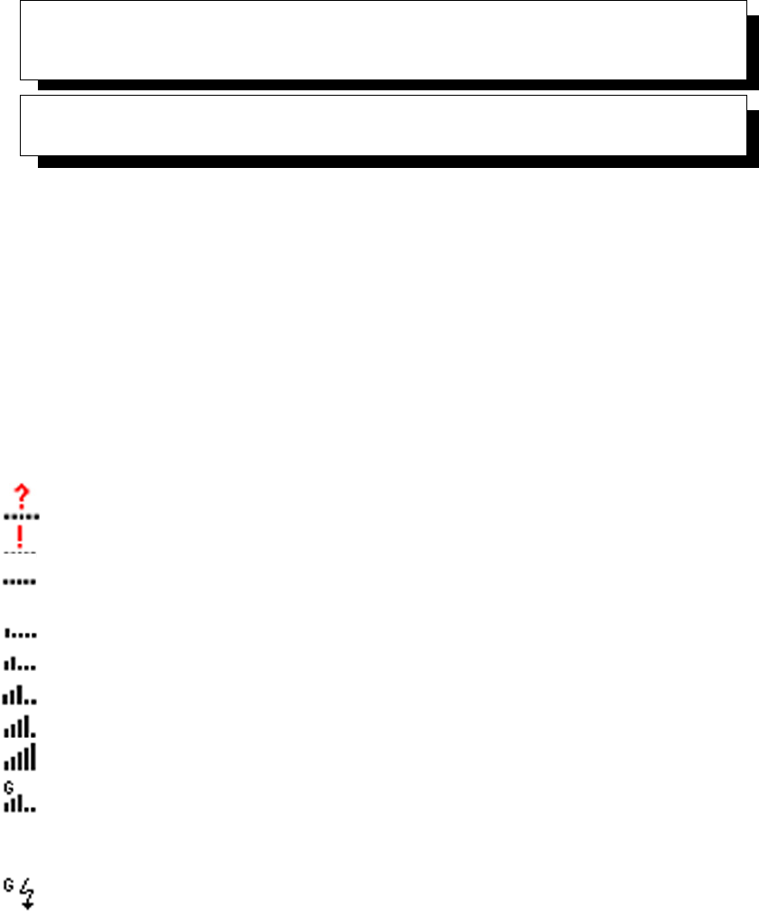
WORKABOUT PRO G2 Hand-Held With Windows Embedded CE 5.0 User Manual B-1
APPENDIX B
WIRELESS WIDE AREA NETWORK (WWAN)
B.1 Wireless WAN
Psion Teklogix offers a quad band, GPRS radio – Model Number RA3030-G2; a WORK-
ABOUT PRO G2 equipped with a GSM/GPRS radio has wide area networking capabilities.
B.1.1 Taskbar Icons
Wireless WAN icons in the taskbar indicate the status of your wide area network connection.
Note that these icons are only visible when a GSM/GPRS radio is installed in the computer,
and the interface is enabled.
The letter in the signal strength icon (G for GSM/GPRS) indicates that a packet data service
is available and initialized. Keep in mind that the signal strength icon is displayed without a
letter if packet data service is not available or if it is available but not yet initialized.
User interaction is required (e.g. the user is required to enter a PIN).
A non-recoverable (fatal) error has occurred.
The modem status is unknown or the modem is not connected to any network (the signal
strength is 0%).
The modem has found a network, and the signal strength is between 1% and 20%.
The modem has found a network, and the signal strength is between 21% and 40%.
The modem has found a network, and the signal strength is between 41% and 60%.
The modem has found a network, and the signal strength is between 61% and 80%.
The modem has found a network, and the signal strength is between 81% and 100%.
A GPRS packet data connection is active, the signal strength is between 41% and 60% and
GSM.GPRS packet service is available.
The signal strength icon is replaced by a connection indicator icon when a packet data con-
nection is started.
A GPRS packet data connection is active.
In addition to the signal strength or connection indicator a second icon may be shown:
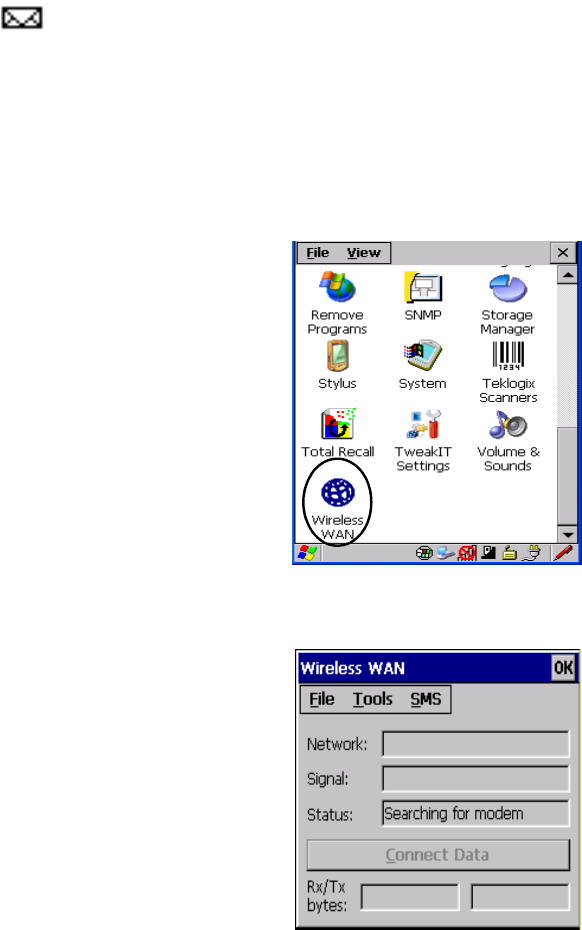
Appendix B: Wireless Wide Area Network (WWAN)
Establishing A Connection
B-2 WORKABOUT PRO G2 Hand-Held With Windows Embedded CE 5.0 User Manual
A new SMS message has arrived.
B.1.2 Establishing A Connection
To display the main Wireless WAN dialog box:
• Double-tap on the Wireless WAN icon in the taskbar.
If the icon is not visible in the taskbar, the radio interface has been shut down or the modem
has been removed:
•In the Control Panel, choose the Wireless WAN icon.
Figure B.1 Wireless WAN Icon
The main Wireless WAN dialog box is displayed.
Figure B.2 Establishing A Connection

WORKABOUT PRO G2 Hand-Held With Windows Embedded CE 5.0 User Manual B-3
Appendix B: Wireless Wide Area Network (WWAN)
Establishing A Connection
Note: If you are prompted to enter a PIN, refer to “Entering A PIN Number” on
page 4 for details.
When “Ready to connect” is displayed in the Status field, the Connect Data button is
enabled.
• Tap on the Connect Data button.
The progress of the connection is tracked in the Status field.
• PPP link to modem active.
• Authenticating user.
• User authenticated.
• Connected.
Note: Keep in mind that these states may be displayed fairly quickly if the
progress of the connection is rapid.
When the connection state reaches PPP link to modem active, the taskbar icon changes to indi-
cate an active connection. The Connect Data button changes
to Disconnect.
Disconnecting From A Network
To disconnect from the network:
• Tap the stylus on the Disconnect button, and then on OK.
When the computer’s network connection is severed, the Status field displays “Ready to
connect”.
The signal strength is displayed in the main Wireless WAN screen, even while a connection
is active. The Rx bytes and Tx bytes fields estimate the amount of data transmitted and
received, respectively.
Shutting Down The Wireless WAN User Interface
While it is not usual to shut down the GSM/GPRS user interface, you can accomplish this by
tapping on the File menu and choosing the Exit command at the bottom of the main Wire-
less WAN dialog box
Note: Once you’ve shut down the user interface, you can only enable the radio
by opening the Control Panel and tapping on the Wireless WAN icon to
display the Wireless WAN dialog box.

Appendix B: Wireless Wide Area Network (WWAN)
Advanced Information
B-4 WORKABOUT PRO G2 Hand-Held With Windows Embedded CE 5.0 User Manual
B.1.3 Advanced Information
In most cases, when a GSM/GPRS radio and SIM are installed in your computer, setup is
automatic. Follow the steps outlined under the heading “Establishing A Connection” on
page 2 to make a connection. The information in this section is for advanced setup purposes.
Entering A PIN Number
If a PIN is required, a PIN entry dialog box is displayed.
• Type your PIN, and press [ENTER].
Note: If you exceed the number of allowable attempts, a PUK entry window is
brought to the foreground. You’ll need to enter a new PIN number.
Once the correct PIN or PUK is entered or if none was required, the modem is instructed to
perform a GSM network registration followed by a GPRS attach.
The main Wireless WAN dialog box reflects the progress of the initialization.
• Searching for modem
• Initializing modem
•SIM is ready
• Searching for network
• Registered on network
• Searching for GPRS
• Ready to connect
If the modem loses the connection to the GSM network, the following states are repeated:
Searching for network, Registered on network, Searching for packet data, and Ready to con-
nect.
Error States
The following temporary error states (i.e., these states may disappear without interaction)
may be displayed:
• Emergency calls only.
The modem has found a network but is not allowed to register (e.g. no
roaming agreement between networks). The modem keeps searching for
another network.
WORKABOUT PRO G2 Hand-Held With Windows Embedded CE 5.0 User Manual B-5
Appendix B: Wireless Wide Area Network (WWAN)
Tools Menu
• No network found.
A network is not currently available. The modem continues searching for
a network.
• Packet data not available.
The current network does not support a packet data service.
• Packet data not allowed.
The modem is not allowed to use the packet data service on the current
network (e.g. no GPRS roaming agreement between network; a roaming
agreement for voice may still be in place). It is also possible that you do not
have a subscription for GPRS at all.
The remaining error states are permanent:
• SIM is missing.
The SIM card is missing. After the SIM has been inserted a warm boot may
be required.
• SIM failure.
The SIM card is permanently disabled (e.g. because the wrong PUK has
been entered too many times). A new SIM is needed.
• Modem failure.
The modem did not respond to commands as expected. If a warm boot does
not clear this condition, the modem may need to be replaced.
• NDIS error.
An internal software error has occurred. If a warm boot does not clear this
condition, Psion Teklogix technical support may need to investigate further.
B.1.4 Tools Menu
The Tools menu in the main Wireless WAN dialog box offers some additional, advanced
setup features.
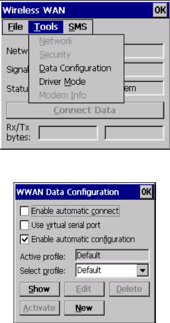
Appendix B: Wireless Wide Area Network (WWAN)
Tools Menu
B-6 WORKABOUT PRO G2 Hand-Held With Windows Embedded CE 5.0 User Manual
WWAN Data Configuration
Enable Automatic Connect
If the Enable automatic connect checkbox is checked (unchecked by default), the Wire-
less WAN user interface will attempt to establish a GPRS connection whenever GPRS is
available (e.g. after resume from suspend without further user interaction).
To activate the automatic connection mode:
• Tap on the OK button.
While automatic connection mode is enabled, the Connect Data button in the main Wire-
less LAN dialog box changes to Disable Auto. To close the currently active connection (if
any) and disable the automatic connection mode:
• Tap on Disable Auto.

WORKABOUT PRO G2 Hand-Held With Windows Embedded CE 5.0 User Manual B-7
Appendix B: Wireless Wide Area Network (WWAN)
Tools Menu
Important: Automatic connection mode should not be used if applications
other than the Wireless WAN user interface (e.g. Connection
Manager) are expected to open and close connections.
If the automatic connection mode is enabled and another applica-
tion closes the GPRS connection, the WWAN user interface will
immediately try to re-establish the connection.
Use Virtual Serial Port
If Use virtual serial port is enabled, packet data connections are established through the
virtual serial port of the WWAN driver rather than through the WWAN driver directly. This
checkbox should only be checked if certain third-party VPN (Virtual Private Network)
clients are used that do not work correctly otherwise. The default setting is disabled
(unchecked).
Notes: The connection setup takes longer through the virtual serial port.
Enable Automatic Configuration
In most cases, the data connection is configured automatically and no user interaction is
required. This is true even if multiple SIM cards from different operators are used with the
same device. The connection parameters are adjusted automatically when a new SIM card is
detected (this may require a warm boot). The connection parameters are retrieved from a
database.
Manual configuration should be necessary only if:
• One or more parameters in the database are incorrect or a new operator is
not yet in the database. (The database should be corrected for subsequent
software releases.)
• An operator has assigned individual GPRS user names and passwords.
• A very large site has their own APN. Such connections always have to be
configured manually.
• A customer has subscribed for a static IP address. By definition this must be
configured manually.
Appendix B: Wireless Wide Area Network (WWAN)
Tools Menu
B-8 WORKABOUT PRO G2 Hand-Held With Windows Embedded CE 5.0 User Manual
Profiles
In the following section, all the parameters that need to be configured for a connection (such
as APN, user name, password, DNS server addresses etc.) are referred to as a profile. Every
profile is identified by an arbitrary, unique name. The profile named Default is special in
that it is always present and can neither be edited nor deleted. The Default profile uses
parameters from a built-in database. The home network (the network that issued the SIM) is
used for the database look-up. While there can be many configured profiles, only one profile
can be active at any time.
If connection profiles are configured manually, the Enable automatic configuration
checkbox should normally be unchecked.
In one particular use case, manually configured profiles may be combined with automatic
configuration. If multiple SIM cards are used with the same device, each SIM card being
from a different operator and some or all of them requiring a manually set up profile, auto-
matic configuration may be used to automatically pick the correct manually configured
profile for each SIM card. For this to work, each profile must be configured while the corre-
sponding SIM card is inserted in the device and initialized (i.e. the status is at least SIM is
ready).
The Select profile: drop-down list in the data configuration profile selects to which profile
a subsequent action applies. A profile named Default is always present and contains the
current parameters from the database. The following actions are available:
Show
The parameters for the selected profile are displayed when you tap the stylus on this button.
For the Default profile, the publicly known password is shown—otherwise, the password is
hidden.
Edit
The parameters of the selected profile can be edited when you choose the Edit button. Keep
in mind that you cannot edit the Default profile.
Delete
The selected profile is deleted. You cannot delete the Default profile.
Activate
When this button is chosen, the selected profile becomes the active profile. Activation is
possible only if the Enable automatic configuration: checkbox
is unchecked.
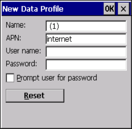
WORKABOUT PRO G2 Hand-Held With Windows Embedded CE 5.0 User Manual B-9
Appendix B: Wireless Wide Area Network (WWAN)
Tools Menu
New
Tapping on the New button allows you to create a new profile.
Figure B.3 Creating A New Profile
The name of the newly created profile must be different from all existing profiles. Also, the
name cannot be Default. When the New Data Profile dialog box is opened, a proposal for
a unique name is filled in the corresponding entry field. If a manually configured profile has
a secret password and unauthorized access to the device is a concern even after the SIM PIN
has been entered, the password should not be entered in the New Data Profile dialog box
and the Prompt user for password checkbox should be checked instead. In this case, you
will be prompted for the password each time a connection is initiated (the Connect Data
button in the main Wireless WAN dialog box is selected).
Reset
The Reset button in the New Profile and Edit Profile dialog boxes resets all entry fields to the
values they had when the dialog box was opened.
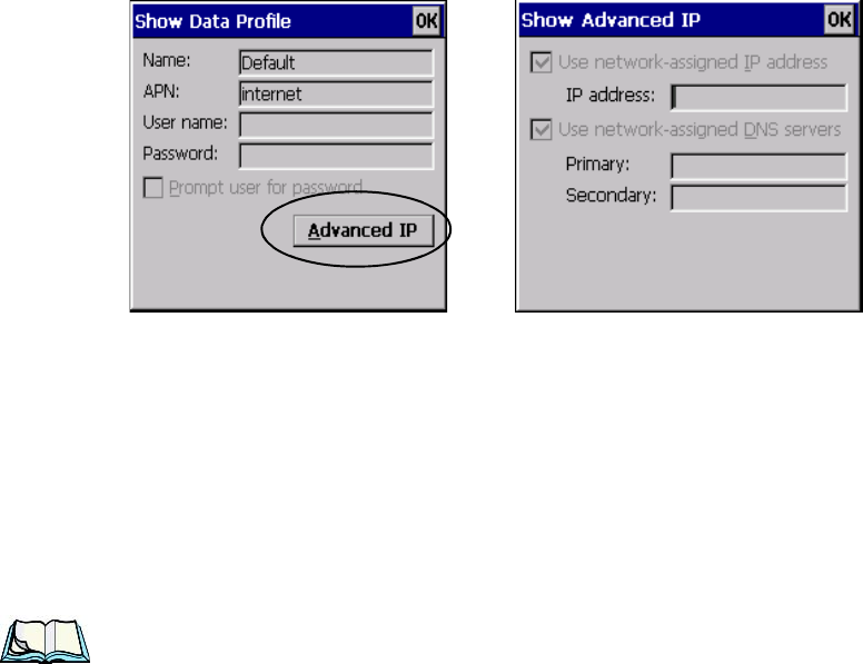
Appendix B: Wireless Wide Area Network (WWAN)
Tools Menu
B-10 WORKABOUT PRO G2 Hand-Held With Windows Embedded CE 5.0 User Manual
Advanced IP
Figure B.4 Assigning IP Information
The Advanced IP button in the Show Profile and Edit Profile dialog boxes opens
another dialog box that allows you to configure a static IP address as well as the IP addresses
for the primary and secondary DNS server.
Security Configuration
The Security Configuration dialog box is accessed through the Tools menu. The Secu-
rity Configuration dialog box allows you to enable, disable and change the PIN. You will
need the current PIN to make any of these changes. The PIN must be enabled in order to be
changed. (If the PIN is disabled, the New PIN entry field is greyed out.)
Note: Keep in mind that some network operators do not allow the SIM PIN to be
disabled. A new PIN must consist of 4 to 8 numeric digits.
The Require PIN on resume checkbox is independent of the aforementioned settings. By
default, this checkbox is unchecked. While this option remains unchecked, any PIN entered
on startup or through the Security Configuration dialog box and submitted successfully to
the modem is stored in memory for as long as the device is not rebooted. This stored PIN is
then used without further user interaction whenever the modem requires a PIN (such as
resume after suspend or modem removal). The stored PIN is also automatically entered in
the Current PIN text box whenever the Security Configuration dialog box is called up.
If unauthorized access to the device is a concern, the Require PIN on resume checkbox
should be checked. In this case, the PIN is not stored; whenever a PIN is required, you will
be prompted to enter an appropriate value.

WORKABOUT PRO G2 Hand-Held With Windows Embedded CE 5.0 User Manual B-11
Appendix B: Wireless Wide Area Network (WWAN)
Tools Menu
Network Configuration
In the main Wireless WAN window:
• Tap on the Tools menu, and choose Network.
By default the GSM radio modem automatically chooses from the available and allowed net-
works (allowed networks are the home network and all other networks with which the home
network has a roaming agreement). You may find there are some situations in which you
want to override this default behaviour. For example, you may want to disable roaming if
you find yourself in a border area where the home network is not available but a foreign
roaming partner is available. Abroad, you may find that an available network does not have
GPRS roaming agreements. In this case, you’ll need to manually select the network which
you know to support GPRS roaming.
Automatic network selection is enabled or disabled by checking or unchecking Enable
automatic network select in the Network dialog box. When automatic network selection
is disabled, you must select a network manually.
Available networks can also be viewed without changing any settings. Scanning for avail-
able networks is a lengthy operation—a progress bar is shown while the scan is active. For
every network that is found, the network name, country, status and numeric network identi-
fier (MCC/MNC, Mobile Country Code followed by the Mobile Network Code) is dis-
played.
Notes: Your home network operator will need to let you know which other net-
works have roaming agreements. Even when a network is listed with an
‘Available’ status, it does not necessarily follow that it can be used or that
the roaming agreement covers GPRS.
A status of ‘Forbidden’ indicates that the network cannot be used. If you
choose a network that is not covered by a roaming agreement, the status in
the main WWAN dialog box changes to ‘Emergency calls only’, ‘No net-
work found’, ‘GPRS not available’ or ‘GPRS not allowed’.
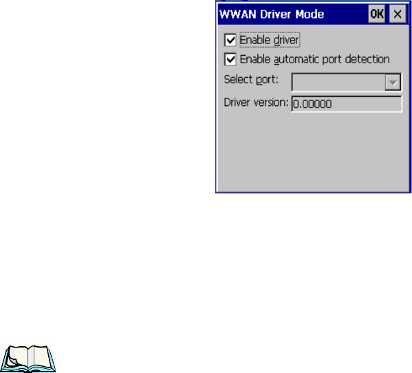
Appendix B: Wireless Wide Area Network (WWAN)
Tools Menu
B-12 WORKABOUT PRO G2 Hand-Held With Windows Embedded CE 5.0 User Manual
Driver Mode Configuration
By default, the Wireless WAN driver is enabled (the Enable driver checkbox is checked).
The driver must be disabled in order to use the modem for anything other than GPRS (e.g.
dial-up data, fax, or in order to manually submit AT commands to the modem for develop-
ment, testing, approvals, etc.). If the Enable driver checkbox is not checked, the driver is
shut down as soon as the OK button in the Driver Mode dialog box is chosen.
If, on the other hand, the Wireless WAN driver is not running and the Enable driver check-
box is checked, the Wireless WAN driver is started as soon the Driver Mode dialog box is
closed using the OK button.
Note: When the driver is not running, no network status or signal strength can
be displayed.
Since all currently supported GSM modems are automatically detected, the Enable auto-
matic port detection checkbox should always be checked. If this checkbox is not checked,
a serial port can be selected manually. This experimental feature allows the driver to be used
with an internal GSM modem that was not recognized by the automatic detection or an
external GSM modem connected to a serial port of the computer through USB or through
Bluetooth. An external modem connected to a serial port must support 115.2kbit/s, 8bit, no
parity and hardware flow control.
Modem Information
The fields in this dialog box cannot be edited, they only display information about the com-
puter’s modem. If the network operator has not programmed a user’s phone number into his
SIM, the Phone: field remains empty. If the main menu shows an error status, at least partial
modem information may be available.
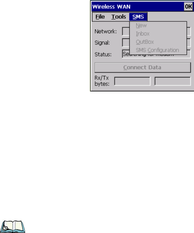
WORKABOUT PRO G2 Hand-Held With Windows Embedded CE 5.0 User Manual B-13
Appendix B: Wireless Wide Area Network (WWAN)
SMS Menu
B.1.5 SMS Menu
SMS functions are accessed through the SMS menu. For modems that support a SIM card,
the SIM initialization typically takes longer than the network initialization, resulting in a
noticeable delay before the SMS functions become available.
New
Tapping on the New button opens a dialog for sending a new SMS message. The recipient's
phone number (to be entered in the To: field) can consist of the digits 0 through 9, as well as
the * and # characters, optionally preceded by one + character, indicating an international
number (i.e. the country code follows immediately after the + character).
By checking the Store message in Outbox field a new message can be stored in the Outbox
before being sent. If no storage space is available, or the modem does not support the storage
of outgoing messages, then this checkbox is disabled.
Inbox
Tapping on the Inbox button opens the list of received messages. Reading 50 messages, for
example, from the SIM can take about 30 seconds. By default the list of messages is sorted
with the most recently received message first. The list can be sorted by any other column by
clicking on the corresponding column heading. Clicking the same column heading twice
reverses the sort order. Pressing any letter or digit moves the highlight to the next message
whose address begins with that letter or number.
Note: The date and time formats can be changed through the Region and
Language menu in Control Panel. For a new date or time format to take
effect the Inbox has to be closed and re-opened.
The Open button opens the selected message in a new window such that the entire message
can be read including the original formatting (line breaks are replaced by spaces in the Inbox

Appendix B: Wireless Wide Area Network (WWAN)
Power Mode
B-14 WORKABOUT PRO G2 Hand-Held With Windows Embedded CE 5.0 User Manual
message list). Pressing the Reply button opens the new message dialog as described above,
except the destination phone number is filled in already.
Outbox
Tapping on the Outbox button opens the list of sent messages. Otherwise the Outbox
behaves exactly as the Inbox described above. The date and time when a message was sent is
not available for GSM modems.
SMS Configuration
Tapping on the SMS Configuration button opens the SMS configuration dialog. The SMS
Centre address follows the same rules as the recipient's phone number in the New message
dialog. The message validity period parameter is sent to the SMS Centre with each message
sent subsequently and instructs the SMS Centre on how long it should attempt to deliver the
message to the recipient (the SMS Centre may impose an upper limit on the validity period
regardless of the setting).
Note: Only certain discrete validity period values can be sent and thus the
validity period is rounded to the nearest allowed value. The next time the
SMS configuration dialog is opened the rounded value is shown.
The user interface tries to keep the SMS storage location available for a new incoming
message if the Delete oldest message when full checkbox is checked. In this case, when a
new message arrives and the SMS storage becomes full, the oldest received message is
deleted. If any string is entered as the Message Suppression Prefix, then messages beginning
with that string will not be shown in either the Inbox or Outbox. In this way messages
intended for another application running on the same device can be hidden from the user, as
long as those messages begin with the string configured here.
B.2 Power Mode
The power mode of the modem is controlled through the Power menu in the Control Panel
(not through the Wireless WAN user interface).
For CF Card modems, the settings are found under the Devices tab. If the checkbox for a
modem is unchecked then no power is applied to the modem and no driver is loaded (neither
the serial port driver nor the Wireless WAN driver). If the checkbox is checked then power is
applied to the modem and the drivers are loaded when the computer is turned on. Power is
removed from the modem when the computer enters suspend mode.

WORKABOUT PRO G2 Hand-Held With Windows Embedded CE 5.0 User Manual I
INDEX
A
Accepted Start Char 177
accessories
belt loop (carrying case) 218
carrying case 218
desktop docking station 223
Ethernet adaptor cable 227
hand strap 215
holster, soft shell 220
pistol grip 217
port replicator 238
quad battery charger 229
quad docking station 232
single battery charger 228
swivel belt loop (carrying case) 218
vehicle cradle 235
Active Conn Tab 117
ActiveSync 227
ASync profile 113
Adaptive Windowing 194
adaptor cable
USB-Ethernet 227
Addendum 182, 195, 196
Addendum Add-on 2 157, 158, 159, 160,
182
Addendum Add-on 5 157, 158, 159, 160,
182
Addendum Required 157, 158, 159, 160
Addendum Separator 157, 158, 159, 160
aiming dot, duration of 137
ALT Key 41
appearance (display colour scheme) 89
Append 156
appending to bar codes
characters 145, 201
approvals, WORKABOUT G2 (including
scanner) 243
arrow keys
moving the cursor 40
ASCII
Full Ascii 176
audio indicators
beep conditions 46
volume adjustment 47
Authentication, Bluetooth Controls 114
Auto Exposure (Imager) 192
Aztec, 2D 198
B
backlight
display 87
intensity 44
keyboard 44
backup battery (ML2032) 12
backup profile, creating (Total Recall) 125
backup profile, restoring (Total Recall)
129
Bad Scan Beep 202
bar code
appending to 145, 201
displaying type of bar code 201
parameters 136
prefix character 143, 144
stripping characters 143, 145
suffix character 143, 145
symbologies
Codabar 149, 161, 183, 196
Code 11 163, 185
Code 128 144, 194
Code 39 194
Code 93 148, 160, 182, 196
Discrete 2 of 5 151, 165, 187
EAN 13 144, 157, 179, 195
EAN 8 145, 158, 180, 195
IATA 2 of 5 164
Interleaved 2 of 5 150, 163, 185,
197
Matrix 2 of 5 164, 186
MSI Plessey 149, 162, 184
UPC A 145, 158, 180, 196
UPC E 146, 159, 181, 196
Translation tab 203
Barcodes Must Decode 191
batteries

II WORKABOUT PRO G2 Hand-Held With Windows Embedded CE 5.0 User Manual
Index
a description of 221
backup (ML2032) 12
capacity dialog box 101
charging 11, 37
gauge 48
installing 36
installing main battery 12
main battery 11
power saving suspend dialog box 101
removing 36
run time 49
storing 50
swap time 37
battery charger
safety instructions 222–223
beeper
beep conditions 46
volume adjustment 47
belt loop, swivel (carrying case) 218
Bi-Direction Redundancy 139
BKSP (DEL Key) 41
Bluetooth radio
changing device name 117
device service profiles 113
ISM band 111
PINs for devices 114
radio configuration 111
Bluetooth setup 111
GPRS setup 118
peripherals 239
Bluetooth specs 244
BooSt
console (cold reset) 32
Bright For (backlight) 88
BSP, Bluetooth Controls 118
C
cable diagrams C-1
calibrating (touchscreen) 45, 105
Captures Per HW Trigger 192
case, carrying 218
Center Bar Code Only (Imager) 190
CH, Bluetooth Controls 114
changing password (Start Menu security)
65
characters
appending to bar codes 145
prefix 143, 144
stripping 143, 145
suffix 143, 145
charger
descriptions of 38
safety instructions 222–223
chargers 221
desktop docking station 223
installing at a site 221
operator controls 222
quad battery charger (WA3004) 229
single battery 228
charging (main battery) 11
Check Char 155, 161, 162, 164
Check Digit 157, 158, 159
check digit 150, 163
Check Digit, One 150, 163
Check Digits (MSI Plessey) 150, 163
Check Digit Verification 142, 177, 179,
184, 185, 186, 187
Check Digit Verification (Codabar) 183
Check Digit Verification (I 2 of 5) 151
cleaning hand-held 52
clean start 32
Click Data (scanner double-click) 201
Click Time (scanner double-click) 201
CLSI Editing 149
CLSI Library System 183
Codabar 149, 161, 183, 196
Codabar 149
Codablock 170, 190
Code 11 163, 185
Code 128 194
Code 128 144, 156, 178
Code 128 Emulation 153, 189
Code 16K 169
Code 32, Convert To 141
Code 32 Prefix 141
Code 39 141, 155, 176
Code 49 170
Code 93 148, 160, 182, 196
Code 93 148
cold reset 32
Cold Reset (Shutdown menu) 71
COM, Bluetooth Controls 118
Command Prompt 66
communication
ActiveSync 227
Ethernet connection (desktop dock)
227
Ethernet connection (quad dock) 232
WORKABOUT to PC 226
Communities 207
Composite 152, 167, 197

WORKABOUT PRO G2 Hand-Held With Windows Embedded CE 5.0 User Manual III
Index
Concatenation 162
connection list table, Bluetooth Controls
117
Constant Illumination 194
Contact 206
Continuous Scan Mode 138, 154, 175,
190
control panel
accessing 81
basic setup 87
Display Properties 87
icons 83
keyboard properties 90
power management properties 100
stylus properties 104
Conv. UPC-E To UPC-A 147
Conv. UPC-E1 To UPC-A 147
Convert To Code 32 141
Convert To EAN 13 151, 180, 181
Convert To UPC -A 181
cradle See also Picker cradle 235
CTRL Key 41
cycle tasks 68
D
Data Matrix, 2D 170, 198
Decoded (HHP) parameters 154
decoded (internal) scanner parameters 137
decoded Intermec (ISCP) parameters 175
Decode Performance 142, 144
Decode Performance Level 143, 144
Decoder Timeout 193
DEL (BKSP) Key 41
Delete Char Set ECIs 140
Demo
Imager 67
Scanner 67
Signature 67
desktop connection, remote 81
desktop docking station (WA4002) 223
Device Name, changing 117
dialog box, using 72
Diff Read Timeout 176
digit
check digit 150, 163
Dim For (backlight) 89
Discrete 2 of 5 151, 165, 187
Discrete 2 of 5 151, 165
dismounting partitions 132
display
appearance (colour scheme) 89
backlight 87
backlight, adjusting 44
Display Properties 87
Display Properties 87
docking device icons 49
docking station
uploading data using 51
docking stations 221
desktop docking station 223
installation at site 221
operator controls 222
quad dock 232
Dot Time 137, 191
double-click
appending characters to a decoded
bar code 201
scanner trigger 201
Double-Click, Manage Triggers menu
107
Double-Tap (stylus settings) 105
DSSS, 802.11g radio 244
DUN service, Bluetooth 113
Duration 137
E
EAN 13 144, 157, 179, 195
EAN 8 145, 158, 180, 195
EAN-8 Zero Extend 145
ECI Decoder 141
Enable Bookland (UPC-EAN) 147
Enable CC-AB 153
Enable CC-C 153
Enable Plessy 184
Enable RSS Expanded 152, 166, 188
Enable RSS Limited 152, 166, 188
Enable RSS-14 152, 188
Enable SNMP 207
Enable TLC-39 153, 168
Encryption, Bluetooth Controls 114
ESC Key 41
EV15 Specs 247
EV15 1D imager scanner specs 247
F
Factory Defaults On Reboot 192
Fast Converge (Imager) 193
features, WORKABOUT PRO G2 7
Field Size 143
Field Size/Chars (bar code scanning) 143

IV WORKABOUT PRO G2 Hand-Held With Windows Embedded CE 5.0 User Manual
Index
FNC1 Conversion 178
formatting
entire memory card 129
partitions 132
Full Ascii 176
Full ASCII (decoded scanner) 142, 156
Function Keys
accessing 42
G
Good Scan Beep 202
GPRS (bluetooth) 118
GSM/GPRS E-1–E-12
GS1-128 178
GS1 128 (Composite bar code) 167
GS1-128 GS1 US 144
GS1-128 Identifier 178
GTIN Compliant 178, 182
H
hand strap 215
holster, soft shell 220
I
IATA 2 of 5 164
Imager
EV15 specs 247
imager parameters 190
indicators
battery gauge 48
docking devices 49
LED functions 46
modifier keys 48
onscreen 47
security level 49
task bar 61
Wireless WAN 49
802.11radio signal quality 49
Input Panel (control panel) 83
Intensity (7035 backlighting) 88
Interleaved 2 of 5 150, 163, 185, 197
Internet Explorer 66
IP address, assigning (Summit) 13
ISBN Conversion 157, 180
ISBT Concat Any Pair 179
ISBT Concatenation 156
ISBT Concat Transmit 178
ISBT 128 144, 178
ISM band, Bluetooth radio 111
K
keyboard
key repeat 90, 91
one shot mode 92
36-key keyboard 43
58-key 42
keyboard backlight 44
keyboard keys 39
ALT 41
arrow keys 40
BKSP 41
CTRL 41
DEL 41
ESC 41
macro keys 42, 93
modifiers 39
navigating using the keyboard 57
one shot mode 92
SCAN 41
SHIFT 40
SPACE 41
TAB 41
Keyboard Properties 90, 91
backlight 91
one shot mode 92
Key Repeat tab 90
keys
alpha keys, 36-key keyboard 43
L
LANAccessUsingPPP service, Bluetooth
113
Laser On Time 138, 154, 175
LED
functions 46
Length Mode 184, 186, 187
LIF (Low Insert Force) port pinout B-1
Linear Decode 148
Linear Security Level 138
Location 207
Low Power Timeout 138, 155, 176
L1, Set Length 142
L2, Set Length 142
M
Macro keys
accessing 42
executing a macro 94
Macros menu, accessing 93
recording and saving 93
maintenance (of hand-held) 52

WORKABOUT PRO G2 Hand-Held With Windows Embedded CE 5.0 User Manual V
Index
Manage Triggers 106
Matrix 2 of 5 164, 186
Max Gain (Imager) 193
Max Illumination (Imager) 193
Maximum Length 155, 157, 161, 162,
163, 164, 165, 166, 167, 168, 169, 170,
171, 172, 173, 174
Max Integration (Imager) 193
Max Number Barcodes 191
memory card
creating partitions 130
formatting entire 129
formatting partition 132
messages
Scan Indicator 201
scanner warning message 201
Scan Result 201
Micro PDF-417 153, 169, 189, 198
Minimum Cancel Time 138, 154, 175
Minimum Length 155, 157, 161, 162,
163, 164, 165, 166, 167, 168, 169, 170,
171, 172, 173, 174, 177, 179, 183, 184,
185, 187, 188
Min Scan Duration 192
modem using VPN clients E-7
modifier keys 39
locking 40
One Shot Mode 92
unlocking 40
mounting partitions 133
MSI Plessey 149, 162, 184
N
Name 208
name servers, assigning (Summit) 16
NOTIS Editing 149
NQuerty Retry, Bluetooth Controls 118
O
Off & On buttons 38
On & Off button 12, 38
One Check Digit 150, 163
One Shot Mode 92
ON For 91
Output (Telepen) 165
P
Parameter Scanning 138, 155, 157, 161,
162, 163, 164, 165, 166, 167, 168, 169,
170, 171, 172, 173, 174, 176, 177, 178,
179, 182, 183, 184, 185, 186, 187, 188
partitions
creating 130
deleting 132
dismounting 132
formatting 132
management 132
mounting 133
PC, connecting WORKABOUT to 226
PDF-417 153, 168, 189, 197
Pharmaceutical 156
picker cradle
installing cable 236
PIN, Bluetooth Controls 113
pinouts C-1
PINs, Bluetooth devices 114
pistol grip 217
Plessey Maximum Length 163
Plessey Minimum Length 163
Plessy Transmit Check Digit 184
pocket PC compatibility 81
port pinouts C-1
Port Prefix, Bluetooth Controls 118
port replicator 238
ports
LIF (Low Insertion Force) B-1
tether B-2
PosiCode 167
Postal
Australian 173
Canadian 173
China 173
Japanese 173
Kix 174
Korean 174
PlaNET 172, 199
PostNET 172, 199
Royal 174, 200
powering up 12
Power Management Properties 100
battery capacity 101
suspend, power saving 101
Power Source 101
Prefix 140
Prefix Char 143, 144
Printer (serial service), Bluetooth 113
profile, creating backup 125
profile, restoring backup 129
Programs

VI WORKABOUT PRO G2 Hand-Held With Windows Embedded CE 5.0 User Manual
Index
Command Prompt 66
Internet Explorer 66
Remote Desktop Connection 66
Windows Explorer 66
protective case 218
punctuation marks, accessing (SHIFT
Key) 40
Q
quad battery charger 229
quad dock (WA4004) 232
R
radio
Bluetooth 111
Bluetooth specs 244
IP address (Summit), assigning 13
name servers (Summit) 16
RA2041 radio specifications 244
specifications 244
802.11g Direct Sequence SS 244
802.11signal quality 49
radio specifications 244
Raster Expand Rate (2D) 140
Raster Height (2D) 140
RA2041 radio specifications 244
Reading Range 177, 179, 182, 186
recalibrating (touchscreen) 45, 105
remote connect 81
Remote Desktop Connection 66
Repeat Delay (between key repeats) 91
Repeat Rate (of key repeats) 91
Repeat tab (key repeat settings) 90
resetting the WORKABOUT
clean start 32
resetting the WORKABOUT PRO G2
BooSt menu, accessing 32
warm reset 31
Rights 208
RSS Code 152, 166, 188, 197
Run (Start Menu) 70
S
safety instructions
battery charger 222–223
Same Read Timeout 176
Same Read Validate 176
Scan Data Format 140
Scan Indicator 201
SCAN Key 41
Scan Log File 202
scanner
Bi-Direction Redundancy 139
CLSI Editing 149
Codabar 149
Code 39 141
Continuous Scan Mode 138
Conv. UPC-E To UPC-A 147
Conv. UPC-E1 To UPC-A 147
decoded (internal) 137
decoded Intermec (ISCP) 175
EAN-8 Zero Extend 145
Enable Bookland 147
imager 190
Laser On Time 175
Linear Security Level 138
Low Power Timeout 138
Minimum Cancel Time 138
NOTIS Editing 149
Parameter Scanning 138
Security Level 148
Supp. Redundancy 147
Supplementals 147
UPC-A Check Digit 145
UPC-A Preamble 146
UPC-EANI 147
UPC-E Check Digit 146
UPC-E Preamble 146
UPC-E1 Check Digit 146
UPC-E1 Preamble 146
2D UPC Half Block Stitching 148
scanner module (SE 955)
specs 245
scanning
aiming (target) dot duration 137
appending characters 145, 201
Bad Scan Beep 202
check digit 150, 163
Check Digits (MSI Plessey) 150, 163
Check Digit Verification 142
Check Digit Verification (I 2 of 5) 151
Click Data (appending data) 201
Click Time 201
Code 128 144, 156, 178
Code 128 Emulation 153
Code 32 Prefix 141
Code 39 155, 176
Code 93 148
Composite 152
Convert To Code 32 141
Convert To EAN 13 151
Decoded (HHP) 154

WORKABOUT PRO G2 Hand-Held With Windows Embedded CE 5.0 User Manual VII
Index
Decode Perf. Level 143, 144
Decode Performance 142, 144
Delete Char Set ECIs 140
Discrete 2 of 5 151
Dot Time 137
double-click 201
ECI Decoder 141
Enable CC-AB 153
Enable CC-C 153
Enable RSS Expanded 152
Enable RSS Limited 152
Enable RSS-14 152
Enable TLC-39 153, 168
Full ASCII 142, 156
Good Scan Beep 202
Laser On Time 138, 154
Linear Decode 148
Micro PDF-417 153
PDF-417 153
Postal
PlaNET 199
PostNET 199
Royal 200
Prefix 140
prefix character 143, 144
removing characters 143, 145
RSS Code 152
Scan Data Format 140
Scan Indicator 201
Scan Log File 202
Scan Result 201
Scan Result Time 201
Set Length L1 142
Set Length L2 142
specifications 245
specifications, imager 248
Suffix 140
suffix character 143, 145
symbologies 136
target (aiming) dot duration 137
Translations tab 203
Transmit Check Digit 142
Transmit Check Digit (I 2 of 5) 151
Transmit Check Digit (MSI Plessey)
150
Transmit Code 1D Char 140
Trioptic Code 39 156
Trioptic Code 39, Enable 141
UPC-EAN Shared Settings 160, 181
2D Maxicode 198
2D QR Code 198
Scanning Mode (2D) 139
Scan Result 201
Scan Result Time 201
screen
stylus, using to navigate 57
touch pen, using 57
Windows CE, navigating 57
SCU (Summit Client Utility) 13
Config Tab 20
configuring 17
Diags (Diagnostics) Tab 30
EAP Credentials 25
EAP Types 23, 25
Global Settings Tab 26
IP, assigning 13
Main Tab 17, 20
security 23
Status Tab 29
ThirdPartyConfig 26
Windows Zero Config (WZC) 26
WLAN, connecting to 13
SD/MMC Card, inserting 51
Security Level 148
security level icon 49
Security Settings 64
changing password 65
configuring taskbar 66
level 65
Supervisor 65
Teklogix 65
User 65
Servers, Bluetooth Controls 115
Services, Bluetooth Controls 113
Set Length L1 142
Set Length L2 142
Set PIN, Bluetooth Controls 114
Settings
Control Panel 69
Network and Dial-up connections 69
Run 69
Taskbar and Start Menu 69
SE 955 scanner specs 245
SHIFT Key 40
Shutdown
Cold Reset 71
Suspend 71
Warm Reset 71
Shutdown (Start Menu) 71
signal quality, 802.11 49
Simple Network Management (SNMP)
See SNMP 205
single battery charger (WA3001) 228

VIII WORKABOUT PRO G2 Hand-Held With Windows Embedded CE 5.0 User Manual
Index
SIP (Soft Input Panel 83
Sled See vehicle cradle. 235
SMS Configuration E-14
SNMP (Simple Network Management
Protocol) 205
Communities 207
Contact 206
Enable SNMP 207
Location 207
Name 208
Rights 208
Soft Input Panel (SIP) 83
Soft Scan Timeout 202
SPACE Key 41
specifications
SE 955 scanner 245
Start/Stop Transmit 161, 177, 183
Start Menu 63
cycle tasks 68
desktop 64
programs 66
Run 70
Security 64
Settings 69
Shutdown 71
system tray 68
task manager 69
Strip Leading 143, 145
Strip Start/Stop Chars 155
Strip Trailing 143, 145
stylus (touch pen), using 57
Stylus Properties 104
Double-tap (stylus sensitivity) 105
Suffix 140
Suffix Char 143, 145
Summit Client Utility (SCU) 13
Supervisor security level 65
Supp. Redundancy (Code 128) 147
Supplementals (UPC-EAN) 147
Suspend (Shutdown menu) 71
Suspend Timeout 102
swap time (for battery) 37
swivel belt loop (carrying case) 218
symbologies, bar code 136
system tray 68
T
TAB Key 41
target dot, duration of 137
taskbar
onscreen indicators
battery gauge 48
docking devices 49
modifier keys 48
security level 49
Wireless WAN 49
802.11 radio signal quality 49
using 61
task manager 69
Teklogix security level 65
TekTerm application 81
Telepen 165, 188
tether port pinout B-2
text conventions 4
TLC-39 168
Total Recall
backup profile, creating 125
backup profile, restoring 129
touch pen, using 57
touchscreen
recalibration 45, 105
stylus, using 57
touch pen, using 57
Translations parameters (bar codes) 203
Transmit Check Digit 177, 180, 181,
183, 184, 185, 186, 187
Transmit Check Digit (I 2 of 5) 151
Transmit Check Digit (MSI Plessey) 150
Transmit Code 1D Char 140
Transmit Number System 159, 160, 180,
181
trigger mappings 107
Trigger-Press Type, Manage Triggers
menu 109
triggers, configuring 106
Trioptic Code 39 156
Trioptic Code 39, Enable 141
U
UPC A 145, 158, 180, 196
UPC-A Check Digit 145
UPC-A Preamble 146
UPC E 146, 159, 181, 196
UPC-EAN 147
UPC-EAN Shared Settings 160, 181
UPC-E Check Digit 146
UPC-E Preamble 146
UPC-E1 Check Digit 146
UPC-E1 Preamble 146

WORKABOUT PRO G2 Hand-Held With Windows Embedded CE 5.0 User Manual IX
Index
UPC Half Block Stitching, 2D 148
USB-Ethernet adaptor cable (WA4010)
227
User security level 65
Use Virtual Serial Port E-7
V
vehicle cradle 235
powered 10-55 VDC 235
powered 12 VDC 235
unpowered 235
W
warm reset 31
Warm Reset (Shutdown menu) 71
warnings 201
Window Height 191
Windows® Start Menu See Start Menu 63
Windows CE
dialog box 72
files, folders, & programs, working
with 58
Windows CE, navigating in 57
Windows Explorer 66
Windows Zero Config (WZC) 26
Window Width 191
Wireless WAN E-1–E-12
SMS Configuration E-14
Use Virtual Serial Port E-7
Wireless WAN icon 49
WORKABOUT G2
approvals 243
WZC (Windows Zero Config) 26
2D Aztec 172
2DAztec 198
2D Data Matrix 170, 198
2D Maxicode 171, 198
2D QR Code 171, 198
2D Raster Expand Rate 140
2D UPC Half Block Stitching 148
36-key keyboard
alpha keys, accessing 43
uppercase letters, creating 43
58-key keyboard 42
802.11g radio 244

WORKABOUT PRO
Hand-Held Computer
Regulatory & Warranty Guide
February 21, 2007 PN 8000126.A
ISO 9001 Certified
Quality Management System
© Copyright 2007 by Psion Teklogix Inc., Mississauga, Ontario, Canada
This document and the information it contains is the property of Psion
Teklogix Inc., is issued in strict confidence, and is not to be reproduced or
copied, in whole or in part, except for the sole purpose of promoting the sale
of Psion Teklogix manufactured goods and services. Furthermore, this docu-
ment is not to be used as a basis for design, manufacture, or sub-contract, or
in any manner detrimental to the interests of Psion Teklogix Inc.
All trademarks are the property of their respective holders.

Return-To-Factory Warranty
Psion Teklogix provides a return to factory warranty on this product for a
period of twelve (12) months in accordance with the statement of Warranty
and Product Support provided at:
www.psionteklogix.com/warranty.
The warranty on Psion Teklogix manufactured equipment does not extend to
any product that has been tampered with, altered, or repaired by any person
other than an employee of an authorized Psion Teklogix service organization.
See Psion Teklogix terms and conditions of sale for full details.
Important: Psion Teklogix warranties take effect on the date of shipment.
Waste Electrical and Electronic Equipment (WEEE) Directive
2002/96/EC
This Product, and its accessories, comply with the requirements of the Waste
Electrical and Electronic Equipment (WEEE) Directive 2002/96/EC.
If your end-of-life Psion Teklogix product or accessory carries a label as
shown here, please contact your local country representative for details on
how to arrange recycling. For a list of international subsidiaries, please go to:
http://www.psionteklogix.com/EnvironmentalCompliance
Restriction on Hazardous Substances (RoHS) Directive 2002/95/EC
What is RoHS?
The European Union has mandated that high environmental standards be met
in the design and manufacture of electronic and electrical products sold in
Europe, to reduce hazardous substances from entering the environment. The
“Restriction on Hazardous Substances Directive (RoHS)” prescribes the max-
imum trace levels of lead, cadmium, mercury, hexavalent chromium, and
flame retardants PBB and PBDE that may be contained in a product. Only
products meeting these high environmental standards may be “placed on the
market” in EU member states after July 1, 2006.

RoHS Logo
Although there is no legal requirement to mark RoHS-compliant products,
Psion Teklogix Inc. indicates its compliance with the directive as follows:
The RoHS logo located either on the back of the product or underneath the
battery in the battery compartment (or on a related accessory such as the
charger or docking station) signifies that the product is RoHS-compliant as per
the EU directive. Other than as noted below, a Psion Teklogix product that
does not have an accompanying RoHS logo signifies that it was placed on the
EU market prior to July 1, 2006, and is thereby exempt from the directive.
Note: Not all accessories or peripherals will have a RoHS logo due to
physical space limitations or as a result of their exempt status.
Disclaimer
Every effort has been made to make this material complete, accurate, and up-
to-date. In addition, changes are periodically added to the information herein;
these changes will be incorporated into new editions of the publication.
Psion Teklogix Inc. reserves the right to make improvements and/or changes
in the product(s) and/or the program(s) described in this document without
notice, and shall not be responsible for any damages, including but not lim-
ited to consequential damages, caused by reliance on the material presented,
including but not limited to typographical errors.

Psion Teklogix WORKABOUT PRO Regulatory & Warranty Guide 1
Table Of Contents
1. Declaration Of Conformity. . . . . . . . . . . . . . . . . . . . . . . . . . . . . . . . 2
2. Safety Summary . . . . . . . . . . . . . . . . . . . . . . . . . . . . . . . . . . . . . . . . 2
3. The Battery . . . . . . . . . . . . . . . . . . . . . . . . . . . . . . . . . . . . . . . . . . . . 9
4. Support Services & Worldwide Offices . . . . . . . . . . . . . . . . . . . . . . 11
4.1 Technical Support . . . . . . . . . . . . . . . . . . . . . . . . . . . . . . . . . . 11
4.2 Product Repairs . . . . . . . . . . . . . . . . . . . . . . . . . . . . . . . . . . . . 12
4.3 Worldwide Offices. . . . . . . . . . . . . . . . . . . . . . . . . . . . . . . . . . 12

2 Psion Teklogix WORKABOUT PRO Regulatory & Warranty Guide
1. Declaration Of Conformity
Declaration of Conformity documents are provided at:
www.psionteklogix.com/DoC
2 . S a f e t y S u m m a r y
CE Marking
When used in a residential, commercial or light industrial environment the
product and its approved UK and European peripherals
fulfil all requirements for CE marking.
R&TTE Directive 1999/5/EC
This equipment complies with the essential requirements of EU Directive
1999/5/EC (Declaration available: www.psionteklogix.com/DoC).
Cet équipement est conforme aux principales caractéristiques définies dans la
Directive européenne RTTE 1999/5/CE. (Déclaration disponible sur le site:
www.psionteklogix.com/DoC).
Die Geräte erfüllen die grundlegenden Anforderungen der RTTE-Richtlinie
(1999/5/EG). (Den Wortlaut der Richtlinie finden Sie unter: www.psiontek-
logix.com/DoC).
Questa apparecchiatura è conforme ai requisiti essenziali della Direttiva
Europea R&TTE 1999/5/CE. (Dichiarazione disponibile sul sito:
www.psionteklogix.com/DoC).
Este equipo cumple los requisitos principales de la Directiva 1995/5/CE de la
UE, “Equipos de Terminales de Radio y Telecomu-nicaciones”. (Declaración
disponible en: www.psionteklogix.com/DoC).
Este equipamento cumpre os requisitos essenciais da Directiva 1999/5/CE do
Parlamento Europeu e do Conselho (Directiva RTT). (Declaração disponível
no endereço: www.psionteklogix.com/DoC).
Ο εξοπλισμός αυτός πληροί τις βασικές απαιτήσεις της κοινοτικής οδηγίας
EU R&TTE 1999/5/EΚ. (Η δήλωση συμμόρφωσης διατίθεται στη
διεύθυνση: www.psionteklogix.com/DoC)

Psion Teklogix WORKABOUT PRO Regulatory & Warranty Guide 3
Deze apparatuur voldoet aan de noodzakelijke vereisten van EU-richtlijn
betreffende radioapparatuur en telecommunicatie-eindappa-ratuur 199/5/EG.
(verklaring beschikbaar: www.psionteklogix.com/DoC).
Dette udstyr opfylder de Væsentlige krav i EU's direktiv 1999/5/EC om
Radio- og teleterminaludstyr. (Erklæring findes på: www.psionteklogix.com/
DoC).
Dette utstyret er i overensstemmelse med hovedkravene i R&TTE-direktivet
(1999/5/EC) fra EU. (Erklæring finnes på: www.psionteklogix.com/DoC).
Utrustningen uppfyller kraven för EU-direktivet 1999/5/EC om ansluten tel-
eutrustning och ömsesidigt erkännande av utrustningens överensstämmelse
(R&TTE). (Förklaringen finns att läsa på: www.psionteklogix.com/DoC).
Tämä laite vastaa EU:n radio- ja telepäätelaitedirektiivin
(EU R&TTE Directive 1999/5/EC) vaatimuksia. (Julkilausuma nähtävillä
osoitteessa: www.psionteklogix.com/DoC).
PSION TEKLOGIX tímto prohlašuje, že
tohle mobilní zařízení
j
e ve sho
d
ě
se základními požadavky a dalšími příslušnými
ustanoveními sm
ě
rnice 1995/5/ES (NV č. 426/2000 Sb.) a
Prohlášení o shod
ě
je k dispozici na www.psionteklogix.com/DoC.
Toto zařízení lze provozovat v České republice na základ
ě
generální licence č. GL - 12/R/2000.
PSION TEKLOGIX týmto vyhlasuje, že
toto mobilné zariadenie
spĺ
ň
a základné požiadavky a všetky príslušné ustanovenia
Smernice 1995/5/ES (NV č. 443/2001 Z.z.) a Vyhlásenie o
zhode je k dispozícii na www.psionteklogix.com/DoC.
Toto zariadenie je možné prevádzkovať v Slovenskej republike
na základe Všeobecného povolenia č. VPR-01/2001.
Настоящото устройство е в съответствие с основните
изисквания на европейската Директива 1999/5/EC
(Декларацията за съответствие може да бъде намерена
на адрес: www.psionteklogix.com/DoC)

4 Psion Teklogix WORKABOUT PRO Regulatory & Warranty Guide
Use of the 802.11 device in France: Owing to French Government
restrictions, the 802.11 device are limited to indoor use. They may be used
outdoors, on private property, only with prior authorization from the French
Ministry of Defense.
Acest echipament satisface cerinţele esenţiale ale Directivei UE 1999/5/EC
(Declaraţia poate fi gasitã pe site-ul: www.psionteklogix.com/DoC)
Oprema je skladna z bistvenimi zahtevami EU direktive 1999/5/EC
(Deklaracija je na voljo: www.psionteklogix.com/DoC)
Käesolev seade vastab EU Direktiivile 1999/5/EC (selgitus saadaval:
www.psionteklogix.com/DoC)
Az eszköz megfelel az EU 1999/5/EC fő direktíváinak (a nyilatkozat
megtalálható: www.psionteklogix.com/DoC)
Š
ī aparatūra nodrošina nepieciešamas ES Direktīvas prasības
(Deklarācija ir pieejama: www.psionteklogix.com/DoC)
Įranga atitinka pagrindinius EU direktyvos 1999/5/EC reikalavimus
(Deklaraciją galima rasti www.psionteklogix.com/DoC)
Dan l-apparat huwa konformi mal-kriterji tad-direttiva ta' l- EU 1999/5/EC
(Din id-dikjarazzjoni tista ssiba fuq is sit www.psionteklogix.com/DoC)
To urządzenie spełnia wymagania zasadnicze dyrektywy Unii
Europejskiej 1999/5/EC (Deklarację zgodności można znaleźć
p
od adresem internetowym www.psionteklogix.com/DoC)
!
Psion Teklogix WORKABOUT PRO Regulatory & Warranty Guide 5
FCC Information To Users
Federal Communication Commission Interference Statement
This equipment has been tested and found to comply with the limits for a
Class B digital device, pursuant to Part 15 of the FCC Rules. These limits are
designed to provide reasonable protection against harmful interference in a
residential installation. This equipment generates, uses and can radiate radio
frequency energy and, if not installed and used in accordance with the
instructions, may cause harmful interference to radio communications. How-
ever, there is no guarantee that interference will not occur in a particular
installation.
If this equipment does cause harmful interference to radio or television
reception, which can be determined by turning the equipment off and on, the
user is encouraged to try to correct the interference by one of the following
measures:
• Reorient or relocate the receiving antenna.
• Increase the separation between the equipment and receiver.
• Connect the equipment into an outlet on a circuit different from that
to which the receiver is connected.
• Consult the dealer or an experienced radio/TV technician
for help.
This device complies with Part 15 of the FCC Rules. Operation is subject to
the following two conditions: (1) This device may not cause harmful interfer-
ence, and (2) this device must accept any interference received, including
interference that may cause undesired operation.
FCC Caution: Any changes or modifications not expressly approved by the
party responsible for compliance could void the user's authority to operate
this equipment.
IMPORTANT NOTE:
FCC Radiation Exposure Statement:
This equipment complies with FCC radiation exposure limits set forth for an
uncontrolled environment under 47 CFR 2.1093 paragraph (d)(2), for use in a
PDA. End users must follow the specific operating instructions for satisfying
RF exposure compliance.
6 Psion Teklogix WORKABOUT PRO Regulatory & Warranty Guide
This transmitter must not be co-located or operating in conjunction with any
other antenna or transmitter.
Some equipment in hospitals and aircraft are not shielded from radio fre-
quency energy. Do not use the device onboard aircraft, or in hospitals, with-
out first obtaining permission.
Do not use near pacemakers. The product may affect the operation of some
medically implanted devices such as pacemakers, causing them to malfunc-
tion. Avoid placing your product next to such devices. Keep a minimum dis-
tance of 20 cm between the device and the product to reduce the risk of
interference. If you have any reason to suspect that interference is taking
place, turn off the device and contact your cardiologist for assistance. For
body worn operation, this device has been tested and meets the FCC RF
exposure guidelines for use with an accessory that contains no metal and
the positions the handset at a minimum 1.5cm from the body.
Note: To maintain compliance with the FCC RF exposure guidelines, if
you wear the device on your body, use the Psion Teklogix approved
carrying case.
Use of non-approved accessories may violate FCC RF exposure
guidelines.
Emissions Information For Canada
This Class B digital apparatus meets all requirements of the Canadian Inter-
ference-Causing Equipment Regulations. When using the 802.11 radio
option, to prevent radio interference, this device is intended to be operated
indoors and away from windows to provide maximum shielding. Equipment
(or its transmit antenna) that is installed outdoors is subject to licensing.
Cet appareil numérique de la classe B respecte toutes les exigences du Règle-
ment sur le matériel brouilleur du Canada. En cas d’utilisation du module
radio 802.11, afin d'éviter toute interférence radio avec le service autorisé,
l'appareil doit être utilisé à l'intérieur, tout en tant éloigné de toute fenêtre afin
de garantir le maximum de protection. Si cet équipement (ou son antenne
émettrice) est installé à l'extérieur, il est alors soumis à licence.
Warning for Australia
The user needs to switch off the device when exposed to areas with potentially
explosive atmospheres such as petrol stations, chemical storage depots and
blasting operations.
Psion Teklogix WORKABOUT PRO Regulatory & Warranty Guide 7
Warning to Users
This product is a Class I/Class II laser product according to CDRH 21 CFR
1040.10 and 1040.11 and Class1/Class 2 laser product according to IEC
60825-1:1993+A1:1997+A2:2001
Laser Warnings
For your own safety, it is critical that you comply with the
following warnings:
Caution!
Do not look into the laser beam or point the beam at people or animals.
Caution!
Using controls or adjustments, or performing procedures other than those
specified herein may result in hazardous radiation exposure.
Caution!
The use of optical instruments with this product will increase
eye hazard.
Do Not Operate In An Explosive Atmosphere
Operating Psion Teklogix equipment where explosive gas is present may
result in an explosion.
Do Not Remove Covers Or Open Enclosures
To avoid injury, the equipment covers and enclosures should only be
removed by qualified service personnel. Do not operate the equipment
without the covers and enclosures properly installed.
Caution!
Danger of explosion if a battery is incorrectly handled, charged,
disposed of or replaced. Replace only with the same or equivalent type
recommended by Psion Teklogix. Dispose of used batteries according to
the instructions described in “The Battery” on page 9. Carefully review
all battery safety issues.
Vorsicht!
Explosiongefahr bei unsachgemäßem Austausch der Batterie Ersatz nur
durch denselben oder einen vom Hersteller empfohlenen gleichwertigen
Typ. Entsorgung gebrauchter Batterien nach Angaben des Herstellers.
8 Psion Teklogix WORKABOUT PRO Regulatory & Warranty Guide
Safety Instructions for the following:
• AC Wall Adaptor,
• Desktop Docking Stations, and
•Tether Cable
For your own safety, it is critical that you comply with the
following warnings:
Caution!
Before use, read all safety instructions for the Docking Station, the hand-
held and the AC Wall Adaptor.
Caution!
To avoid the risk of fire or personal injury, use only the Psion Teklogix
recommended AC adaptor.
Caution!
Use of an attachment not recommended or sold by Psion Teklogix may
result in fire, electric shock, or personal injury.
Caution!
To reduce risk of damage to the electric plug and cord when unplugging
the charger, pull the plug rather than the cord.
Caution!
Make sure the cord is positioned so that it is not stepped on, tripped over,
or otherwise subjected to damage or stress.
Caution!
Do not operate with a damaged cord or plug. Replace immediately.
Caution!
Do not operate if the device has received a sharp blow, been dropped,
or otherwise damaged in any way; it should be inspected by qualified
service personnel.
Caution!
Do not disassemble; repairs must be carried out by Psion Teklogix quali-
fied service personnel. Incorrect reassembly may result in electric shock
or fire.

Psion Teklogix WORKABOUT PRO Regulatory & Warranty Guide 9
Caution!
To reduce risk of electric shock, unplug the AC adapter from the outlet
before attempting any cleaning.
Caution!
An extension cord should not be used unless absolutely necessary. Use of
an improper extension cord could result in fire or electric shock. If an
extension cord must be used, make sure the plug pins on the extension
cord are the same number, size, and shape as those on the adapter, the
extension cord is properly wired and in good electrical condition and that
the wire size is larger than 16 AWG.
Caution!
The AC adaptor is for indoor use only. Do not expose the AC adaptor to
rain or snow.
3. The Battery
Battery must be fully charged before first use.
Warning: Before charging or using the battery pack, it is critical that the
safety information in this section be reviewed and that all warn-
ings are strictly followed.
BATTERIES ARE CONSIDERED HAZARDOUS WASTE.
For proper disposal, forward all used batteries to one of:
Psion Teklogix Inc. Psion Teklogix Corp. Psion Teklogix S.A.
2100 Meadowvale Blvd. 1810 Airport Exchange Blvd. Parc Club Du Golf-Bat 1.
Mississauga, Ontario Suite 500 13856 Aix-En-Provence
Canada Erlanger, Kentucky Cedex 3
L5N 7J9 USA 41018 France
*The label of this device will be put under the battery compartment.
10 Psion Teklogix WORKABOUT PRO Regulatory & Warranty Guide
Warning: TO PREVENT the battery from leaking acid, generating heat
or exploding, adhere to precautions below.
• The battery incorporates built-in safety devices. To ensure their
proper function, do not disassemble or alter any parts of the battery.
• Do not short-circuit the battery by directly connecting any of the
exposed terminals with metal objects such as wire. Do not transport
or store the battery together with metal objects such as necklaces,
hair pins, etc.
• Do not dispose of batteries in fire as they may explode or release
toxic materials and cause burns.
• Do not use or leave the battery near a heat source such as a fire
or heater.
• Do not immerse the battery in water.
• When charging, use the battery charger specifically designed for the
battery.
• Do not pierce, strike, throw or step on the battery.
• Do not directly solder the battery.
• Do not connect the battery to an electrical outlet, vehicle
cigarette lighter, etc.
• Do not put battery into a microwave oven or pressurized
container.
• Do not use the battery in combination with primary batteries (such as
dry-cell batteries) or batteries of different capacities or brands.
• Immediately remove the battery from the device or battery charger
and stop use if the battery gives off an odour, generates heat,
becomes discoloured or deformed, or in any way appears abnormal
during use.
• Do not continue charging the battery if it does not recharge within the
specified charge time.
• The battery may burst or ignite if the battery leaks. Always ensure
that it is away from any exposed flames.
• If leaking electrolyte sprays into your eyes, rinse them with clean
running water, and immediately seek medical attention.

Psion Teklogix WORKABOUT PRO Regulatory & Warranty Guide 11
• Do not store the battery in extremely high temperatures
(e.g., a vehicle, strong direct sunlight, etc.). This may cause the bat-
tery to overheat or ignite, and it may also reduce the performance and
service life of the battery.
• Do not use in areas where static electricity is greater than what the
manufacturer guarantees.
• Keep batteries out of reach of children.
4. Support Services & Worldwide Offices
Psion Teklogix provides a complete range of product support services to its cus-
tomers worldwide. These services include technical support and product repairs.
4.1 Technical Support
For technical support in North America:
Call Toll free: +1 800 387 8898 Option 3, or
Direct Dial: +1 905 813 9900 Ext. 1999 Option 3.
For technical support in EMEA (Europe, Middle East and Africa), please
contact the local office listed in the website below:
http://www.psionteklogix.com/EMEASupport
For technical support in Asia, please contact the local office listed in the
website below:
http://www.psionteklogix.com
Technical Support for Mobile Computing Products is provided via email
through the Psion Teklogix customer and partner extranets. To reach the web-
site, go to www.psionteklogix.com, and click on the appropriate Teknet link
on the home page. Then click on the “Login” button or the “Register” button,
depending on whether you have previously registered for Teknet. Once you
have logged in, search for the “Support Request Form”.
12 Psion Teklogix WORKABOUT PRO Regulatory & Warranty Guide
4.2 Product Repairs
For repair service in North America:
Call Toll free: +1 800 387 8898 Option 2 or
Direct Dial: +1 905 813 9900 Ext. 1999 Option 2.
For repair service in EMEA (Europe, Middle East and Africa), please
contact the local office listed in the following website:
http://www.psionteklogix.com/EMEASupport
For repair service in Asia, please contact the local office listed in the
website below:
http://www.psionteklogix.com
4.3 Worldwide Offices
COMPANY HEADQUARTERS
Psion Teklogix Inc.
2100 Meadowvale Boulevard
Mississauga
Ontario
Canada L5N 7J9
Tel: +1 905 813 9900
Fax: +1 905 812 6300
Email: salescdn@psion.com
CANADIAN SERVICE CENTRE
Psion Teklogix Inc.
7170 West Credit Ave., Unit #1
Mississauga, Ontario
Canada L5N 7J9
Tel: +1 800 387 8898 Option 2 - or -
Direct: + 1 905 813 9900 Ext. 1999 Option 2
Fax: + 1 905 812 6304
Web: www.psionteklogix.com
Psion Teklogix WORKABOUT PRO Regulatory & Warranty Guide 13
NORTH AMERICAN HEADQUARTERS AND U.S. SERVICE CENTRE
Psion Teklogix Corp.
1810 Airport Exchange Boulevard
Suite 500
Erlanger, Kentucky
USA 41018
Tel: +1 859 371 6006
Fax: +1 859 371 6422
Email: salesusa@psion.com
INTERNATIONAL SUBSIDIARIES
(see also www.psionteklogix.com/Subsidiaries)
Psion Teklogix S.A.
La Duranne
135 Rue Rene Descartes
BP 421000
13591 Aix-En-Provence
Cedex 3; France
Tel: +33 4 42 90 88 09
Fax: +33 4 42 90 88 88
E-mail: tekeuro@psion.com