Psion 7527BHC Handheld PC with GSM/EDGE/WCDMA and BT User Manual 7535 G2 Hand Held Computer
Psion Inc Handheld PC with GSM/EDGE/WCDMA and BT 7535 G2 Hand Held Computer
UserManual.wiki
>
Psion
>
7527BHC User Manual
>
Guide
Contents
1.
Regulatory
2.
Guide
Guide
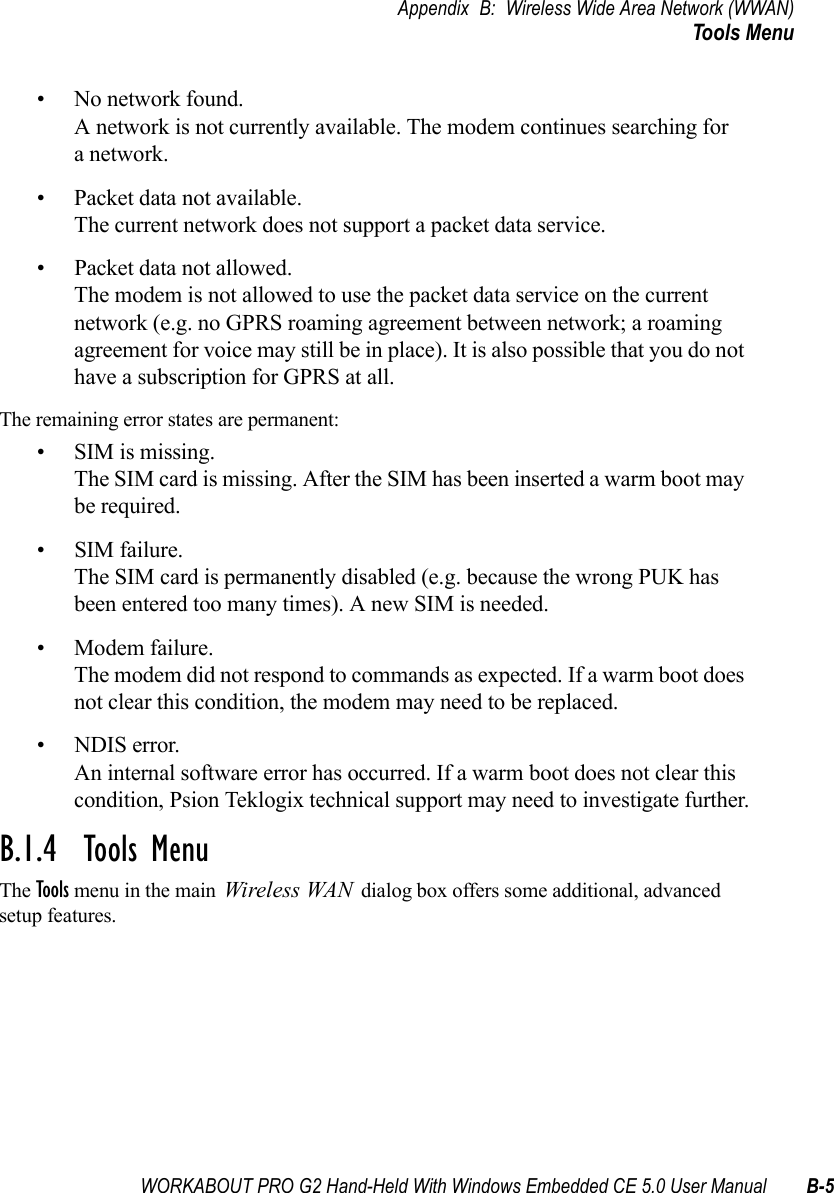
Navigation menu
Upload a User Manual
Namespaces
Wiki Guide
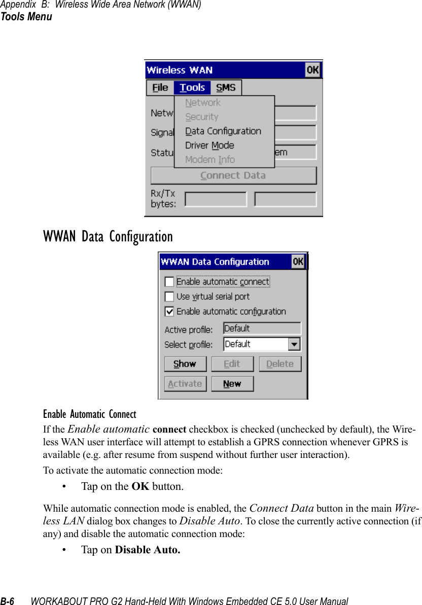
HTML
PDF
Info
Views
User Manual
Discussion / Help
Navigation


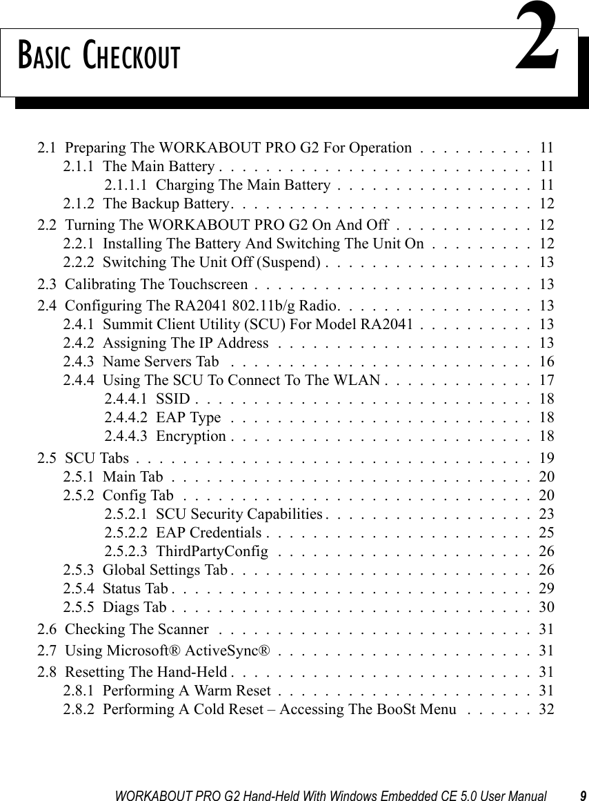
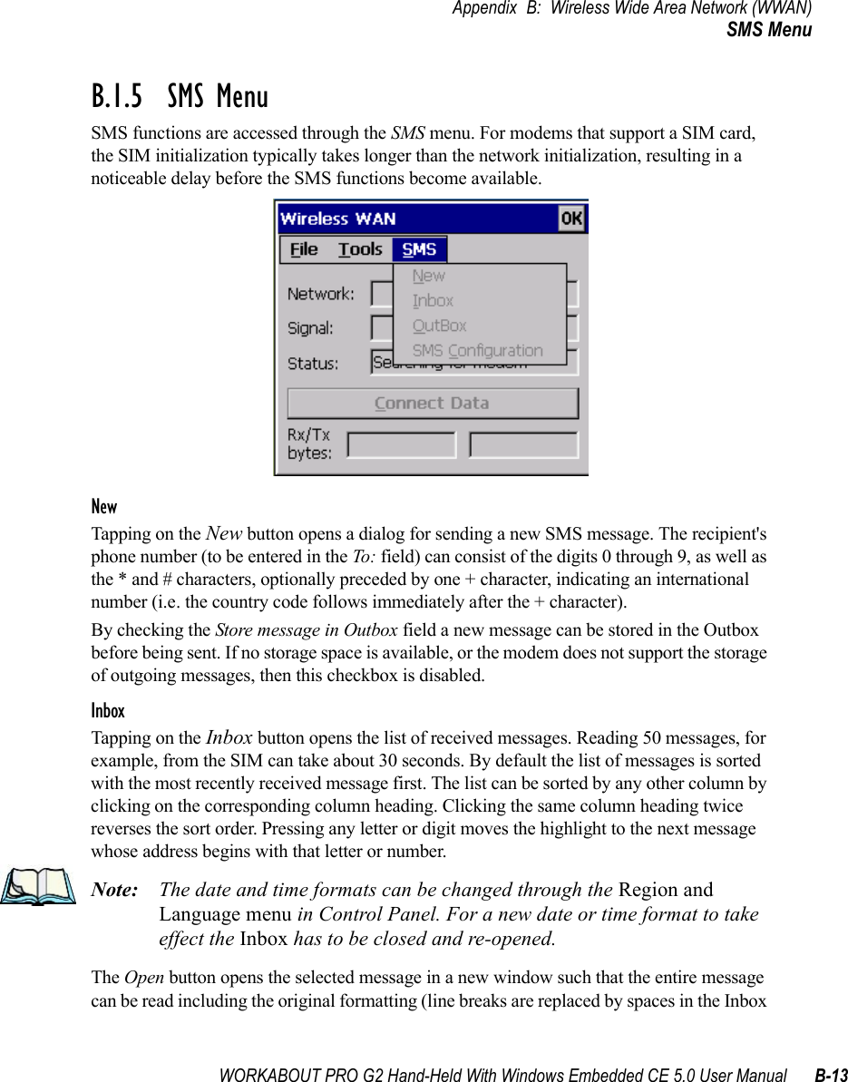
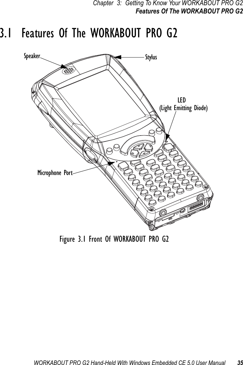
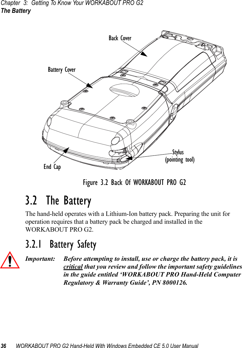
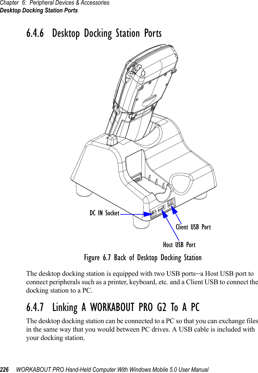
![WORKABOUT PRO G2 Hand-Held With Windows Embedded CE 5.0 User Manual 11Chapter 2: Basic CheckoutPreparing The WORKABOUT PRO G2 For Operation2.1 Preparing The WORKABOUT PRO G2 For Operation2.1.1 The Main BatteryWarning: Before charging the battery, it is critical that you review the battery safety guidelines in the “WORKABOUT PRO Hand-Held Com-puter Warranty & Regulatory Guide”, PN 8000126. The WORKABOUT PRO C G2 and WORKABOUT PRO S G2 can be powered with one of the following lithium-in battery packs:• High-Capacity Battery Pack – 3000mAh• Super High-Capacity Battery Pack – 4000mAh2.1.1.1 Charging The Main BatteryImportant: Before opening the battery cover on your WORKABOUT PRO G2, press [BLUE] [ENTER] to turn off the hand-held. When the battery cover is removed, a power-off switch is automatically acti-vated and the unit power is switched off; if the battery cover is opened while the hand-held is still powered on, the unit may reboot.Battery packs shipped from the factory are charged to approximately 40% and must be fully charged prior to use. Batteries can be charged using a variety of chargers and docking stations along with a WORKABOUT PRO G2 internal charger. When using the internal charger, a suitable power source is required. All chargers and docking stations are described in Chapter 6: Peripheral Devices & Accessories beginning on page 213.Note: If you are powering up a new unit, a warning message may appear on the screen indicating that the backup battery capacity is low. To recharge the internal battery, you must fully charge the WORKABOUT PRO G2 with the main battery installed in the unit. An overnight charge is recom-mended.](https://usermanual.wiki/Psion/7527BHC.Guide/User-Guide-884072-Page-19.png)
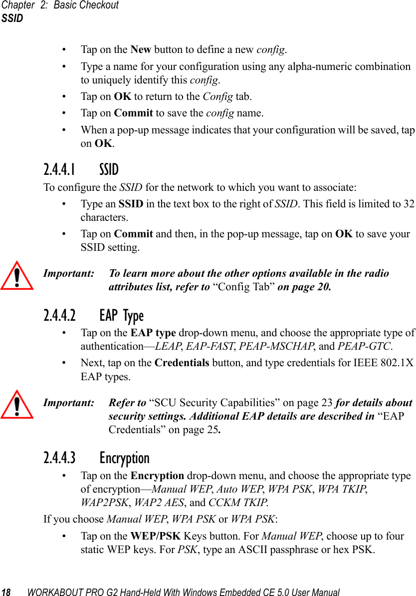
![Chapter 2: Basic CheckoutThe Backup Battery12 WORKABOUT PRO G2 Hand-Held With Windows Embedded CE 5.0 User Manual2.1.2 The Backup BatteryTo preserve data stored in your WORKABOUT PRO G2 while you swap the main battery, the unit is equipped with an internal backup battery–a standard Lithium Alloy Manganese Dioxide coin battery–a Maxell ML2032. The backup battery will supply 5 minutes of continuous power while you install a charged, main battery.The backup battery is trickle charged from the main battery. Provided that the main battery contains power, the backup battery will maintain a charge whether the WORKABOUT PRO G2 is switched on or off, in a docking station or in a cradle. Even when the main battery reaches its Suspend Threshold (refer to “Suspend Threshold” on page 102) and the hand-held shuts down, the backup battery will continue to draw a trickle charge from the main battery to protect the data stored in the unit until a charged main battery is installed.Note: The backup battery takes approximately 100 hrs to fully charge from a fully discharged (flat) state. While you can continue to use the WORK-ABOUT PRO G2, replacing the main battery while the backup battery is not fully charged is not recommended because you risk losing the data stored on the unit.2.2 Turning The WORKABOUT PRO G2 On And Off2.2.1 Installing The Battery And Switching The Unit On• To unlock the battery cover, turn the left-hand battery fastener to the left, and turn the right-hand battery fastener to the right. The top of the stylus is slot-shaped to help you loosen the fasteners.• Remove the battery cover.• Ensure that the ON/OFF switch in the battery compartment is set to ON before inserting the battery.• Snap the charged battery into the unit. Replace the battery cover, and lock the fasteners in place.Note: If you are using a docking station or an external power supply, you can insert an uncharged battery, dock the unit and switch it on. To switch on the WORKABOUT PRO G2:• Press and hold down the [ENTER/ON] key for at least one second.• When the LED flashes green, release the [ENTER/ON] button.](https://usermanual.wiki/Psion/7527BHC.Guide/User-Guide-884072-Page-20.png)
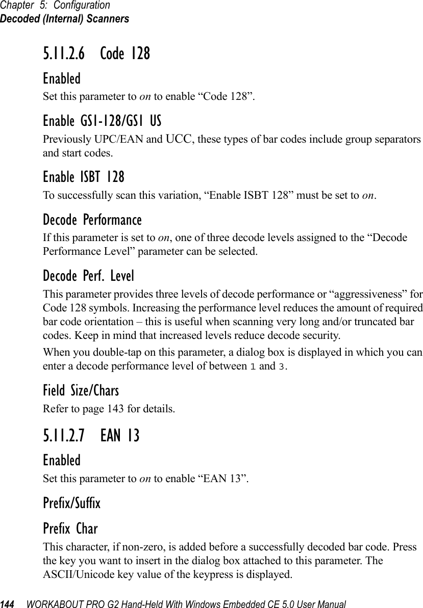
![WORKABOUT PRO G2 Hand-Held With Windows Embedded CE 5.0 User Manual 13Chapter 2: Basic CheckoutSwitching The Unit Off (Suspend)The desktop screen is displayed.Note: If the unit was already in use–the unit may be off (suspend state)–press-ing [ENTER/ON] ‘wakes’ the unit from this state. The screen in which you were working prior to the suspend state is displayed.2.2.2 Switching The Unit Off (Suspend)• Press the [BLUE] key, and then press [ENTER/ON].2.3 Calibrating The TouchscreenNote: Keep in mind that the touchscreen function can be turned off (see “Touch” on page 105).The WORKABOUT PRO G2 touchscreen is factory-calibrated and ready-to-go; however, over time the touchscreen operating parameters may change, and it may need to be recalibrated for correct operation. Refer to “Calibrating The Touchscreen” on page 45 for details.2.4 Configuring The RA2041 802.11b/g RadioPsion Teklogix supports an 802.11b/g Compact Flash (CF) wireless LAN radio card, model number RA2041. It is a Direct Sequence Spread Spectrum radio.If your WORKABOUT PRO G2 is equipped with an RA2041 CF radio, follow the steps under “Summit Client Utility (SCU) For Model RA2041” below to set up this type of radio for communication with a wireless LAN.2.4.1 Summit Client Utility (SCU) For Model RA2041This section describes the Summit Client Utility (SCU). The SCU provides the utilities you will need to configure the Summit 802.11b/g Compact Flash radio module, model number RA2041 so that it can communicate through a wireless LAN effectively and securely. 2.4.2 Assigning The IP AddressBefore launching the SCU, you need to configure how the IP address will be obtained. If your network is not using a DHCP server, you will need to assign anIP address.](https://usermanual.wiki/Psion/7527BHC.Guide/User-Guide-884072-Page-21.png)
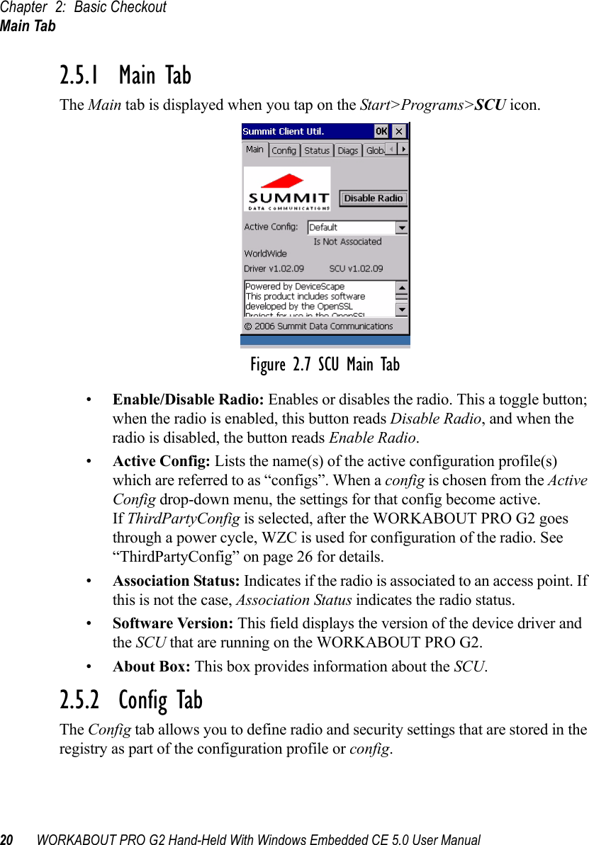
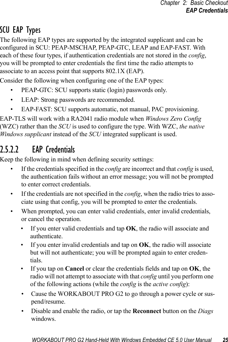
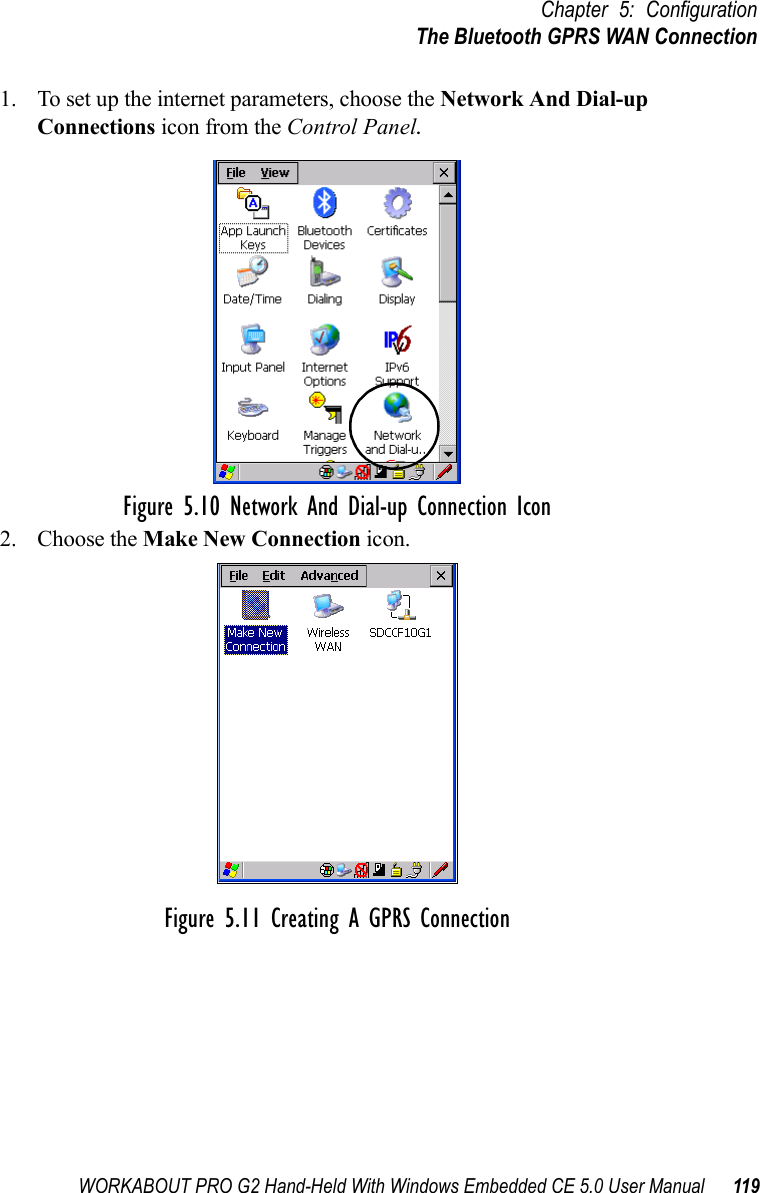
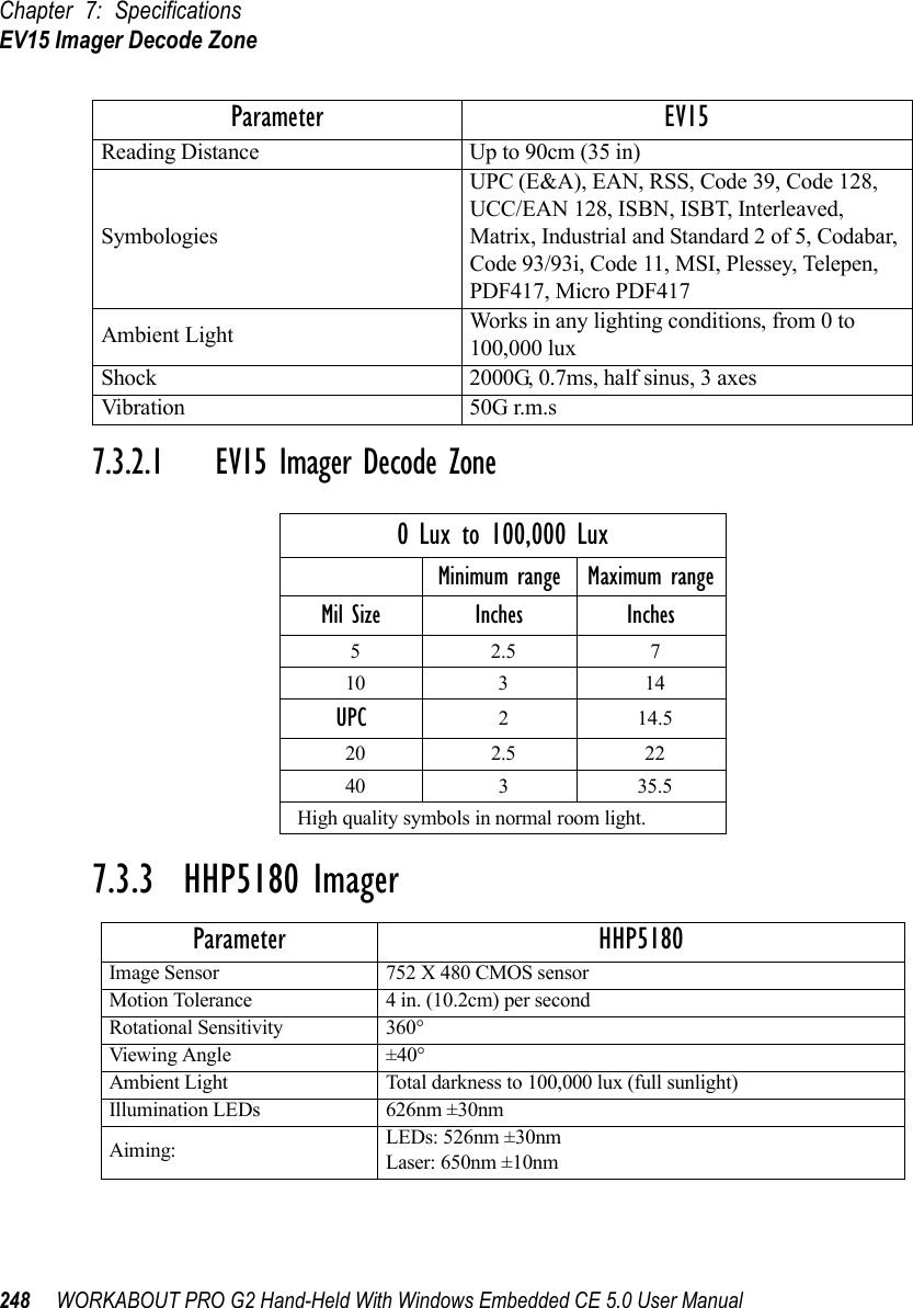
![Chapter 2: Basic CheckoutAssigning The IP Address14 WORKABOUT PRO G2 Hand-Held With Windows Embedded CE 5.0 User Manual1. Tap on Start>Settings>Network and Dial-up Connections. (If the Start Menu isn’t displayed in the taskbar, press [BLUE] [0] to display it.)If you’re using the keyboard, press [BLUE] [0] to display the Start Menu. Use the [DOWN] arrow key to highlight Settings. Press the [RIGHT] arrow key to display the sub-menu. Highlight Network, and press [ENTER].2. Choose the Summit WLAN Adapter icon to open the 802.11b/g Wire-less LAN Settings window. In Figure 2.1, this icon is labelled SDCCF10G1.Figure 2.1 Summit WLAN Adapter IconThe Summit WLAN Adapter Settings menu is displayed (In this screen shown as the SDCCF10G1 menu).](https://usermanual.wiki/Psion/7527BHC.Guide/User-Guide-884072-Page-22.png)
![WORKABOUT PRO G2 Hand-Held With Windows Embedded CE 5.0 User Manual 31Chapter 2: Basic CheckoutChecking The Scanner2.6 Checking The ScannerIf your WORKABOUT PRO G2 is equipped with an internal scanner, you can test it to ensure that it is operating properly. Point the scanner window at a bar code that your scanner was designed to decode—for example, a 1D UPC bar code or 2D bar code. Press the SCAN button or pistol trigger, and check for a valid decode on the hand-held’s screen.Performance is improved if you disable all unneeded bar codes in the Bar Codes screen. Review “Scanner Settings” on page 135 for details about bar codes.2.7 Using Microsoft® ActiveSync®ActiveSync®—Microsoft PC connectivity software—can be used to connect the hand-held to PCs running this software.Note: Keep in mind that you’ll need to run the USB Setup program to configure your workstation before connecting the WORKABOUT PRO G2 via USB. By connecting the WORKABOUT PRO G2 to a PC with a cable and running ActiveSync on the PC, you can:• View WORKABOUT PRO G2 files from Windows Explorer.• Drag and drop files between the WORKABOUT PRO G2 and the PC in the same way that you would between PC drives.• Back up WORKABOUT PRO G2 files to the PC, then restore them from the PC to the hand-held again, if needed, and so on.To install ActiveSync, follow the step-by-step instructions provided with the program’s setup wizard. Refer to the following website for details: http://www.microsoft.com/windowsmobile/addons/default.mspx2.8 Resetting The Hand-Held2.8.1 Performing A Warm ResetTo execute a warm reset:• Press and hold down the [BLUE] key and the [ENTER/ON] key simulta-neously for a minimum of six seconds.A warm reset closes open applications; any unsaved data are lost. Installed programs and saved data are preserved.](https://usermanual.wiki/Psion/7527BHC.Guide/User-Guide-884072-Page-39.png)
![Chapter 2: Basic CheckoutPerforming A Cold Reset – Accessing The BooSt Menu32 WORKABOUT PRO G2 Hand-Held With Windows Embedded CE 5.0 User ManualNote: You do not need to reset your WORKABOUT PRO G2 after configuring the radio.2.8.2 Performing A Cold Reset – Accessing The BooSt Menu• Press and hold down the centre [SCAN] key and then press the [BLUE] and [ENTER] keys simultaneously for a minimum of six seconds.After a cold reset, the BooSt menu appears, listing possible BooSt commands.• To load the Windows Embedded CE 5.0 operating system, type 1.Note: Authorized personnel can perform a ‘clean start’. A clean start resets not only the registry settings to factory defaults, but also erases any files or applications stored or installed on the built-in flash file sys-tem. After a clean start, anything that is not part of the OS image is erased. Only data stored on a SD/MMC card or externally to the device on a USB memory stick or on a PC is preserved during a clean start.](https://usermanual.wiki/Psion/7527BHC.Guide/User-Guide-884072-Page-40.png)
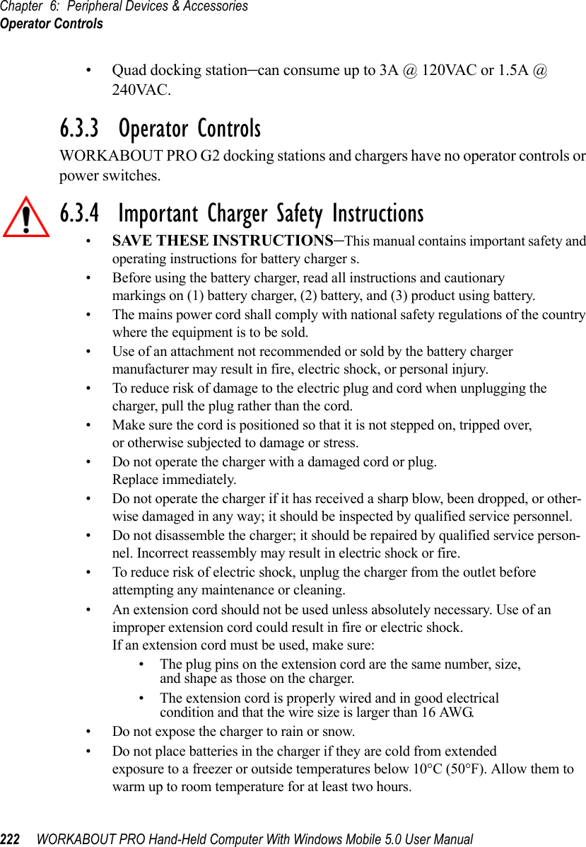
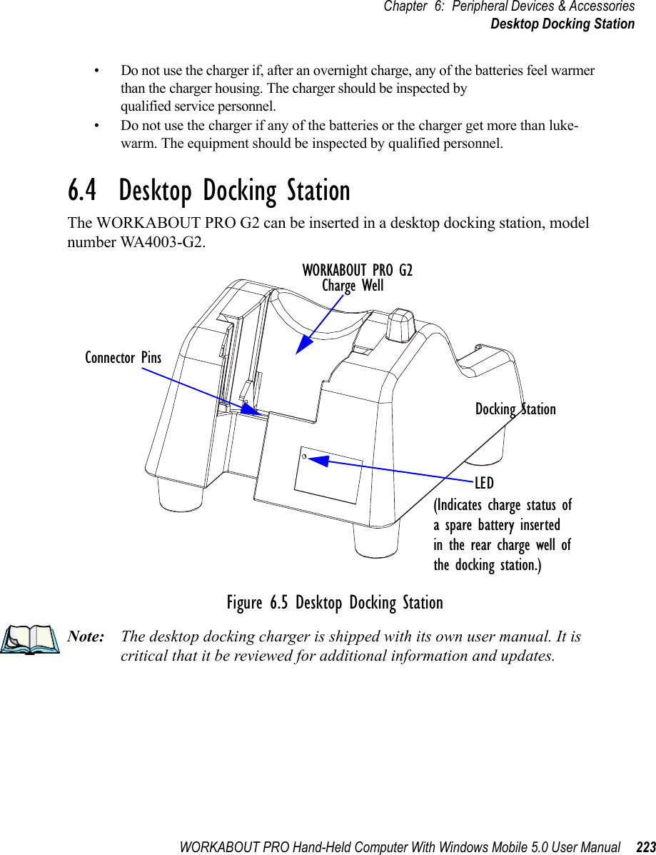
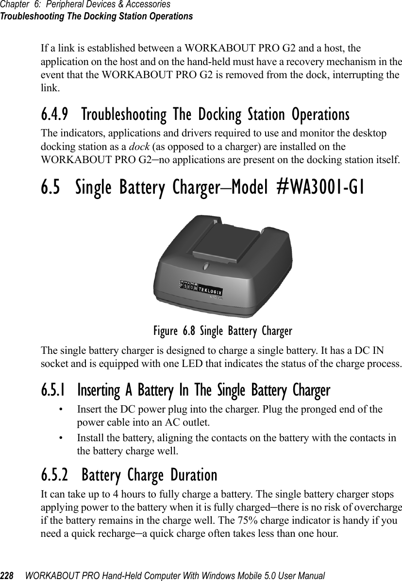
![Chapter 3: Getting To Know Your WORKABOUT PRO G2Chargers And Docking Stations38 WORKABOUT PRO G2 Hand-Held With Windows Embedded CE 5.0 User Manual3.2.3.1 Chargers And Docking StationsImportant: FOR DETAILED INFORMATION about chargers and docking stations, refer to “Peripheral Devices & Accessories” on page 213.Lithium Ion battery packs must be charged before use. These batteries can be charged with a variety of chargers and docking stations. These include:• Desktop Docking Station (Model # WA4003-G2)—operates as both a charger and a docking station. Operating as a charger, both the battery installed in the hand-held and a spare battery can be charged simulta-neously.• Quad Docking Station (Model # WA4004-G1)—can charge the battery of up to four WORKABOUT PROs inserted in the docking station.• Single Battery Charger (Model # WA3001-G1)—charges a single battery.• Quad Battery Charger (Model # WA3004-G1)—charges up to four spare Standard or High-Capacity WORKABOUT PRO battery packs.It can take up to 5 hours to charge a battery. The WORKABOUT PRO intelligent charging system protects the battery from over-charging by terminating the charge process when the battery is at maximum capacity.Note: Refer to “Monitoring The Battery And Maximizing Run Time” on page 49 for additional information about the battery.Important: To avoid damaging the battery, chargers will not begin the charge process until the battery temperature is between 0° C to 45 °C (32° F to 113° F).3.3 Switching The Hand-Held On And OffSwitching On The WORKABOUT PRO G2Note: Whenever the battery cover is removed, an auto-shutoff switch is acti-vated. The battery cover must be installed before the unit can be switched on.• Press and hold down the [ENTER/ON] key for at least one second. • When the LED flashes green, release the [ENTER/ON] button.](https://usermanual.wiki/Psion/7527BHC.Guide/User-Guide-884072-Page-46.png)
![WORKABOUT PRO G2 Hand-Held With Windows Embedded CE 5.0 User Manual 39Chapter 3: Getting To Know Your WORKABOUT PRO G2The KeyboardIf the unit does not power up, the power ON/OFF switch located in the battery compartment may be set to OFF. In this case, you’ll need to remove the battery cover and battery and slide the ON/OFF switch to ON.The startup screen is displayed.Note: If the WORKABOUT PRO G2 is in suspend state, pressing [ENTER/ON] key ‘wakes’ the unit from this state. The screen in which you were working before the computer entered suspend state is displayed.Switching Off The WORKABOUT PRO G2 (Suspend)Important: Keep in mind that turning off the WORKABOUT PRO does not result in a complete reboot; rather, the unit enters a power-saving, “suspend” state. When the unit is turned on from suspend state, operation resumes within a few seconds. To switch off the WORKABOUT PRO G2:• Press the [BLUE] key, and then press the [ENTER/ON] key.3.4 The KeyboardThe WORKABOUT PRO G2 is available in two models, each with it’s own keyboard layout. The WORKABOUT PRO C G2 model is equipped with a 52-key, alphanumeric keyboard; the WORKABOUT PRO S G2 model is equipped with a 25-key numeric keyboard.Most of the keys on these keyboards operate much like a desktop computer. Where a key or key function is not consistent with the PC keyboard, the differences are noted.The [FN/BLUE] and [FN/ORANGE] modifier keys provide access to additional keys and system functions. These functions are colour coded in orange and blue print above the keyboard keys.3.4.1 Modifier KeysThe [SHIFT], [CTRL], [ALT], [FN/BLUE] and [FN/ORANGE] keys are modifier keys. Pressing a modifier key changes the function of the next key pressed. For example, on a WORKABOUT PRO C G2, 52-key keyboard, a square bracket is printed in orange print above the [4] key. Pressing the [FN/ORANGE] key followed by the [4] key displays a square bracket rather than the number 4.](https://usermanual.wiki/Psion/7527BHC.Guide/User-Guide-884072-Page-47.png)
![Chapter 3: Getting To Know Your WORKABOUT PRO G2Activating Modifier Keys40 WORKABOUT PRO G2 Hand-Held With Windows Embedded CE 5.0 User ManualThe [SHIFT], [CTRL] and [ALT] keys operate much like a desktop keyboard except that they are not chorded (two keys held down simultaneously). The modifier key must be pressed first followed by the key whose function you want modified.3.4.1.1 Activating Modifier KeysWhen a modifier key is pressed once, it is displayed in lowercase letters in the taskbar at the bottom of the hand-held screen. For example, if the [CTRL] key is pressed, ctrl key is displayed at the bottom of the unit screen. Once the next key is pressed, the modifier key becomes inactive and disappears from the taskbar. Keep in mind, however, that the ‘One Shot’ function allows you to determine how many key presses will lock a modifier key ‘on’ – one press or two. Refer to “Keyboard One Shot Modes” on page 92 for details.3.4.1.2 Locking Modifier KeysWhen a modifier key is pressed twice, it is ‘locked’ on. A ‘locked’ modifier key is displayed in uppercase letters in the taskbar. For example, pressing the [CTRL] key twice locks it on—it is displayed as CTRL KEY in the taskbar at the bottom of the computer screen.The locked modifier key will remain active until it is pressed a third time to unlock or turn it off. Once a modifier key is unlocked, the uppercase representation at the bottom of the screen is no longer displayed.3.4.2 The KeysThe [SHIFT] KeyThe [SHIFT] key is used to display uppercase alpha characters and provide access to the symbols above the numeric keys.The Arrow KeysThe Arrow keys move the cursor around the screen in the direction of the arrow: up, down, left and right. The cursor is the flashing box or underline character that indicates where the next character you type will appear.](https://usermanual.wiki/Psion/7527BHC.Guide/User-Guide-884072-Page-48.png)
![WORKABOUT PRO G2 Hand-Held With Windows Embedded CE 5.0 User Manual 41Chapter 3: Getting To Know Your WORKABOUT PRO G2Function Keys And Macro KeysThe [SPACE] KeyPressing this key inserts a blank space between characters. In a Windows dialog box, pressing the [SPACE] key enables or disables a checkbox. On WORKABOUT PRO S G2 models, this key is accessed by key combination – [FN/ORANGE] [0] (zero).The [BKSP/DEL] KeyThe [BKSP] key (sometimes referred to as destructive backspace) moves the cursor one character to the left, erasing the incorrectly entered key stroke. The [DEL] key ([FN/BLUE] [BKSP]) erases the character at the cursor position.The [CTRL] And [ALT] KeyThe [CTRL] and [ALT] keys modify the function of the next key pressed and are application dependent. The [TAB] KeyTypically, the [TAB] key moves the cursor to the next field to the right or downward.The [ESC] KeyGenerally, this key is used as a keyboard shortcut to close the current menu, dialog box or activity and return to the previous one.The [SCAN] KeysAll units are equipped with three yellow [SCAN] keys – one on the left side and one on the right side of the unit along with a curved, yellow scan bar just below the WORKABOUT PRO G2 display. For units that do not have internal scanners, this key can be re-mapped to another function.3.4.3 Function Keys And Macro KeysIn addition to the standard keyboard functions, the WORKABOUT PRO G2 supports Function keys and Macro keys. All Function and Macro keys can be custom defined for each application.](https://usermanual.wiki/Psion/7527BHC.Guide/User-Guide-884072-Page-49.png)
![Chapter 3: Getting To Know Your WORKABOUT PRO G2Function Keys42 WORKABOUT PRO G2 Hand-Held With Windows Embedded CE 5.0 User Manual3.4.3.1 Function KeysThe WORKABOUT PRO G2 keyboard is equipped with a total of 14 function keys. Function keys [F1] to [F4] are located across the top of the keyboard next to the [TAB], [ALT], [CTRL] and [ESC] keys and are directly accessible – a key combination is not required. Ten additional function keys are colour coded in blue print on the unit body; these keys are accessed by executing a key combination, [FN/BLUE] followed by the appropriate numeric key.For example, to access function key [F7]:• Press the [FN/BLUE] key followed by the [7] key – the numeric key to which function key [F7] is mapped.• To access function key [F8], press [FN/BLUE] [8], and so on.3.4.3.2 Macro Keys (WORKABOUT PRO C G2 Only)Important: Refer to “Keyboard Macro Keys” on page 93 for details about creating macros. WORKABOUT PRO G2 hand-helds are equipped with a series of macro keys that can be programmed to replace frequently used keystrokes, along with the function of executable keys like the [ENTER] key, the [BKSP] key, any function key and arrow key, and so on. Alphanumeric (52-keys) keyboards have three macro keys: [M1] to [M3]. These keys are colour coded in orange print above alpha keys [O], [P] and [Q].To access a macro key:• Press the [FN/ORANGE] key followed by the appropriate alpha key from [O] to [Q]. To access macro key [M1], press [FN/ORANGE] [O].To access macro key [M2], press [FN/ORANGE] [P], and so on.3.4.4 52-Key Keyboard – Accessing Alpha KeysThe alpha and numeric keys on WORKABOUT PRO C G2 units are directly accessible from the keyboard – no key combination is required. 3.4.5 25-Key Keyboard – Accessing Alphanumeric KeysOn 25-key WORKABOUT PRO G2s, while numeric keys are directly accessible, all alpha characters are printed on the unit plastic in orange typeface above the numeric keys. An indicator in the left corner of the taskbar displays the currently](https://usermanual.wiki/Psion/7527BHC.Guide/User-Guide-884072-Page-50.png)
![WORKABOUT PRO G2 Hand-Held With Windows Embedded CE 5.0 User Manual 43Chapter 3: Getting To Know Your WORKABOUT PRO G225-Key Keyboard – Accessing Alphanumeric Keysselected character. To access an alpha character, first press the [ORANGE] key and then press the numeric key above which the alpha character you want to type is printed. Choosing A Single Alpha CharacterThe examples below illustrate how to access, A, B and C, all of which are printed in orange characters above the numeric key [2].Important: The letters you choose appear in the taskbar, providing a visual indicator of which letter will be displayed on the screen.To choose the letter a:• Press the [FN/ORANGE] key, and press the numeric key [2].Note: To choose the second, third or fourth alpha character assigned to a numeric key, you may want to lock the [FN/ORANGE] key ‘on’. By default, the [FN/ORANGE] key is locked ‘on’ when pressed once. How-ever, depending on how your unit is set up in the ‘One Shots’ tab, you may find that you need to press the [ALPHA/ORANGE] key twice to lock it ‘on’. Refer to “Keyboard One Shot Modes” on page 92for details.To choose the second letter in the sequence—in this example, the letter b:• Lock the [FN/ORANGE] key ‘on’. ‘ORG KEY is displayed in upper-case characters in the taskbar to indicate that this key is locked ‘on’.• Press numeric key [2] twice to display the letter b.To choose the third letter in the sequence—in this example, the letter c:• Lock the [ALPHA/ORANGE] key ‘on’. • Press numeric key [2] three times to display the letter c.Note: Keep in mind that there is a timeout if you pause for one second between key presses when selecting the second, third or fourth letters on a key. For example, suppose you want to type the letter ‘c’–you’d need to press the [2] key three times. With the [FN/ORANGE] key locked ‘on’, if you press [2] twice and then pause between key presses for 1 second, the letter ‘b’ will be selected automatically.Creating Uppercase LettersTo display a capital letter:](https://usermanual.wiki/Psion/7527BHC.Guide/User-Guide-884072-Page-51.png)
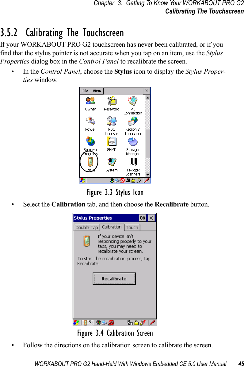
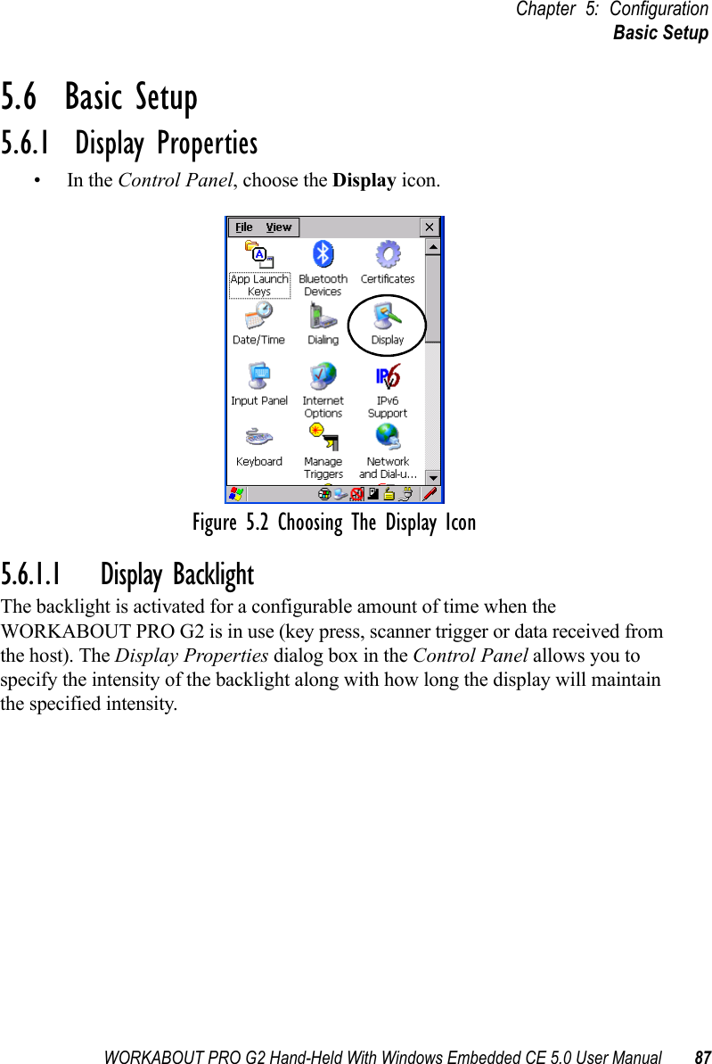
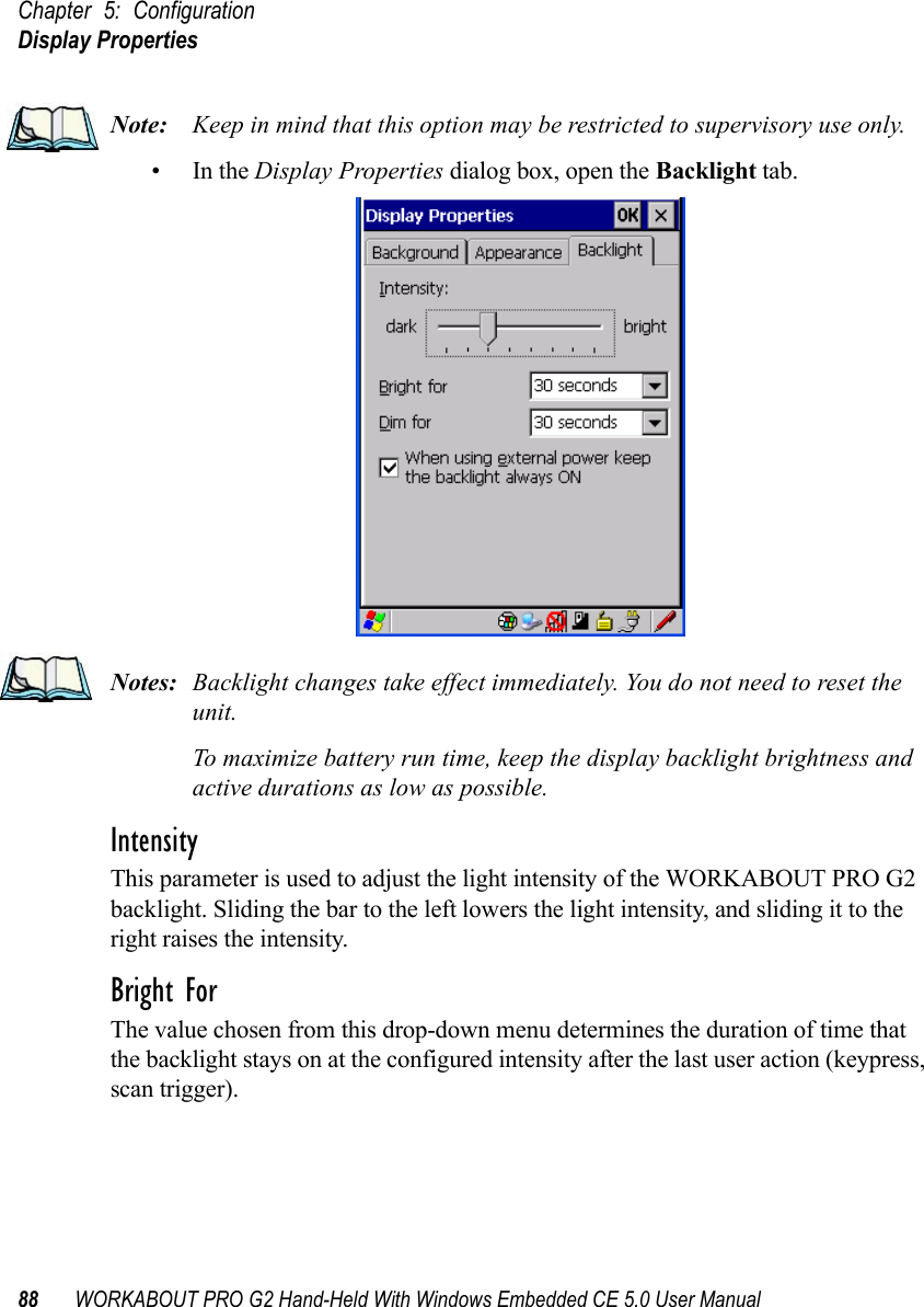
![Chapter 3: Getting To Know Your WORKABOUT PRO G2The Keypad Backlight44 WORKABOUT PRO G2 Hand-Held With Windows Embedded CE 5.0 User Manual• Press the [FN/ORANGE] key and then the [SHIFT] key before typing the alpha character.Note: If you want to use uppercase characters at all times, press [FN/BLUE] [SHIFT]. An icon of an uppercase ‘A’ is displayed in the taskbar indicating that all letters will be displayed as uppercase characters.Choosing Multiple Alpha Characters• Lock the [FN/ORANGE] key ‘on’.Each time you press a numeric key from [2] through [9], an alpha character will be displayed on the screen. Remember that you can refer to the softkey bar for a visual indication of which alpha key will be displayed on the screen.•Once you have finished typing alpha characters, remember to turn off or unlock the [FN/ORANGE] key.3.4.6 The Keypad BacklightThe intensity of the keypad backlight and the conditions under which this backlight is activated can be configured using the Keyboard icon in the Windows Embedded CE 5.0 Control Panel. The behaviour of the keypad backlight is tailored in the Keyboard Properties dialog box. Refer to “Keyboard Backlight” on page 91 for details about this option.Note: Keep in mind that this option may be restricted to supervisory use only.3.5 The DisplayWORKABOUT PRO G2s are equipped with display backlighting to improve character visibility in low light conditions. The backlight switches on when a key is pressed and the ambient light is below the set threshold.3.5.1 Adjusting The Display BacklightThe Display Properties dialog box in the Control Panel allows you to determine the behaviour of the display backlight and its intensityNote: Refer to “Display Backlight” on page 87 for details about the Display Properties dialog box.](https://usermanual.wiki/Psion/7527BHC.Guide/User-Guide-884072-Page-52.png)
![Chapter 3: Getting To Know Your WORKABOUT PRO G2WORKABOUT PRO G2 Indicators46 WORKABOUT PRO G2 Hand-Held With Windows Embedded CE 5.0 User Manual3.6 WORKABOUT PRO G2 IndicatorsThe WORKABOUT PRO G2 uses an LED (Light Emitting Diode), onscreen messages and audio tones to indicate the various conditions of the hand-held, the batteries, the scans and so on.3.6.1 LEDA single, two-coloured LED is located on the upper-right side of the keyboard, just above the [ON] key. When you press [ON], the LED flashes green to indicate that the unit has been powered up. The LED table following outlines the behaviour of the LED while the unit is docked in a charger.Keep in mind that the application running on the WORKABOUT PRO G2 can dictate how the LED operates. Review the documentation provided with your application to determine LED behaviour. If the unit is attached to an external power supply, the hand-held LED reflects the battery charge status.3.6.2 Audio IndicatorsThe audio speaker provides a variety of sounds when a key is pressed, a keyboard character is rejected, scan input is accepted or rejected, an operator’s entry does not match in a match field or the battery is low. To specify how you want your WORKABOUT PRO G2 to respond under various conditions, refer to “Volume And Sound Properties” on page 99.The volume keys are located above [UP ARROW] and [DOWN ARROW]. The increase volume key is labelled with a plus symbol and the decrease volume key is labelled with a minus symbol .LED Behaviour Charge StatusSolid Green Charge complete.Fast Blinking Green Charge in progress. Battery charged to less than 80% capacity.Slow Blinking Green Battery charged to greater than 80% of capacity.Solid Red Temperature outside charge range (0° C to 50° C).Blinking Red Battery is not charging. Battery fault.](https://usermanual.wiki/Psion/7527BHC.Guide/User-Guide-884072-Page-54.png)
![WORKABOUT PRO G2 Hand-Held With Windows Embedded CE 5.0 User Manual 47Chapter 3: Getting To Know Your WORKABOUT PRO G2Adjusting WORKABOUT PRO G2 Speaker Volume3.6.2.1 Adjusting WORKABOUT PRO G2 Speaker Volume• Lock the [FN/BLUE] key ‘on’ and then, press [UP ARROW]—the increase volume key or [DOWN ARROW]—the decrease volume key until the volume meets your requirements.• Remember to press the [FN/BLUE] key again to turn it ‘off’.3.6.3 Onscreen IndicatorsThe taskbar at the bottom of the screen displays a variety of system status indicators.Figure 3.5 TaskbarThe taskbar changes dynamically, and only those icons that are applicable are displayed. For example, if a radio is not installed in your WORKABOUT PRO G2, the radio signal icon is not displayed in the taskbar.Windows® Start ButtonIf you are using the touchscreen, you can either tap the Windows icon at the bottom left of the screen, or press [FN/BLUE] [.] (period) to display the Start Menu, and then tap on the desired application.](https://usermanual.wiki/Psion/7527BHC.Guide/User-Guide-884072-Page-55.png)
![Chapter 3: Getting To Know Your WORKABOUT PRO G2Onscreen Indicators48 WORKABOUT PRO G2 Hand-Held With Windows Embedded CE 5.0 User ManualModifier Key Indicators[SHIFT], [CTRL], [ALT], [FN/BLUE] and [FN/ORANGE] are modifier keys that when pressed, are displayed in the taskbar to indicate that they are active. If a modifier key is locked ‘on’, it is displayed in uppercase characters. For example, if the [FN/BLUE] key is locked on, it is displayed as BLUE KEY in the taskbar. A locked modifier key remains active until it is pressed again to unlock or turn it off. If a modifier key has been pressed but is not locked on, it is displayed in the taskbar in lowercase characters – for example, blue key. It will remain active only until the next key is pressed at which point, the modifier key is turned off.Note: The locking function of the modifier keys can be set up so that pressing one of these keys once will lock the key ‘on’. They can also be set up so that they must be pressed twice to be locked ‘on’. Refer to “Keyboard One Shot Modes” on page 92for details.Battery GaugeThe battery shaped icon displayed in the taskbar provides a visual indication of the remaining battery power. The icon acts as a meter that is either full, at three-quarter level, half, quarter level or empty.When the battery level is low—approximately 15 minutes from empty—a warning window pops up. When the battery power is completely depleted, a final warning window indicates that the WORKABOUT PRO G2 will be powered down.If the WORKABOUT PRO G2 is using external AC power, an AC icon is displayed in the taskbar.Battery ChargeThe battery charge icon is displayed in the taskbar when the hand-held battery is being charged.AC ConnectionFull75%50% 25% Empty](https://usermanual.wiki/Psion/7527BHC.Guide/User-Guide-884072-Page-56.png)
![Chapter 4: Working With Windows Embedded CE 5.0Working With Files, Folders And Programs58 WORKABOUT PRO G2 Hand-Held With Windows Embedded CE 5.0 User ManualTable 4.1 Keyboard NavigationKeep in mind that unlike a desktop computer, the WORKABOUT PRO G2 does not support key chording (pressing two keys at the same time). You must press one key followed by the next in sequence. Refer to “Working With Files, Folders And Programs” for additional details about keyboard navigation.4.2 Working With Files, Folders And ProgramsFigure 4.1 Working With Windows IconsOperation Key or Key CombinationSwitch between active applications [ALT] [TAB]Open task manager [ALT] [ESC]Move the cursor Arrow keysOpen file, folder or icon [ENTER]Exit & Save [ENTER]Close/Exit & Do Not Save [ESC]Navigate Dialog Boxes[TAB]To move cursor up [SHIFT] [TAB]To display the contents of the next ‘tab’ in a dialog box [CTRL] [TAB]Select Radio Button/Press Button [SPACE]Go to Start Menu [BLUE][0]FolderFileProgram Icon](https://usermanual.wiki/Psion/7527BHC.Guide/User-Guide-884072-Page-66.png)
![WORKABOUT PRO G2 Hand-Held With Windows Embedded CE 5.0 User Manual 59Chapter 4: Working With Windows Embedded CE 5.0The Startup Desktop• Double-tap on the appropriate icon—either a folder icon, a program icon or a file icon—to open or launch your selection.If you’re using the keyboard:• Use the arrow keys to highlight the icon you want to open or launch.• Press [ENTER].4.3 The Startup DesktopWhen the WORKABOUT PRO G2 boots up, the startup desktop (shell) is displayed. Any applications stored in the Startup folder start up immediately.Note: The startup folder is located in \Windows\StartUp and \Flash Disk\StartUp.Figure 4.2 The WORKABOUT PRO G2 Startup DesktopTo access desktop icons:• Double-tap on the icon to open a window or, in the case of an application icon, launch an application.On the keyboard:• Use the arrow keys to highlight the icon, and press [ENTER] to launch the highlighted icon.Note: If the arrow keys do not highlight the desktop icons, the desktop may not be selected. Press [FN/BLUE] [.] (period) to display the Start Menu, and](https://usermanual.wiki/Psion/7527BHC.Guide/User-Guide-884072-Page-67.png)
![WORKABOUT PRO G2 Hand-Held With Windows Embedded CE 5.0 User Manual 61Chapter 4: Working With Windows Embedded CE 5.0The Taskbar4.3.2 The TaskbarFigure 4.3 The TaskbarThe WORKABOUT PRO G2 is equipped with a taskbar at the bottom of the screen. It displays icons through which you can view the battery capacity and radio signal quality of your unit. If the hand-held is attached to a charger, cradle, docking station or PDM, an associated icon is displayed. In addition, the taskbar displays the application(s) currently running on your unit and the security level assigned to your WORKABOUT PRO G2.The taskbar also displays active modifier keys: [SHIFT], [ALT], [CTRL], [FN/BLUE] and [FN/ORANGE]. Keys that have been locked “on” are displayed in uppercase letters. For example, if you have set the [CTRL] key Lock to “on” in the Keyboard menu and you press the key, it is displayed as CTRL KEY in the taskbar. (For detailed information on modifier keys and keyboard options, see “The Keyboard” on page 39).4.3.2.1 Using The TaskbarA tooltip is displayed as each taskbar icon is highlighted. The tooltip provides the status of each icon.If you’re using the touchscreen:• Tap and hold the stylus on an icon to display the icon's tooltip. Double-tap the icon to open the Control Panel dialog box associated with the icon. For example, double-tap the battery icon to display a dialog box listing the current battery capacity information.](https://usermanual.wiki/Psion/7527BHC.Guide/User-Guide-884072-Page-69.png)
![Chapter 4: Working With Windows Embedded CE 5.0The Taskbar62 WORKABOUT PRO G2 Hand-Held With Windows Embedded CE 5.0 User ManualOn the keyboard:• Press [FN/BLUE] [.] (period) to display the Start Menu.• Choose Shortcuts from the Start Menu, and then press the [RIGHT] arrow key to display the sub-menu.• Choose System Tray in the sub-menu. • Use the arrow keys to highlight the icon in the taskbar about which you’d like more information.• Press [ENTER] to display the appropriate dialog box.4.3.2.2 Customizing The TaskbarTo customize the taskbar so that it displays only those icons you require:•In the Start Menu, choose Settings, and then Taskbar.If you’re using the keyboard:• Press [BLUE] [0] (zero) to display the Start Menu.• Highlight the Settings option, highlight Taskbar in the sub-menu, and press [ENTER]. The Taskbar and Start Menu dialog box is displayed. Figure 4.4 Taskbar And Start Menu Settings• Tap the stylus on the items you want to activate or deactivate. The check mark indicates active items.If you’re using the keyboard:• Highlight the options you want to activate, and press the [SPACE] key to select them. A check mark indicates active items.](https://usermanual.wiki/Psion/7527BHC.Guide/User-Guide-884072-Page-70.png)
![WORKABOUT PRO G2 Hand-Held With Windows Embedded CE 5.0 User Manual 63Chapter 4: Working With Windows Embedded CE 5.0The Start Menu4.4 The Start MenuNote: Some of the Start Menu items may be disabled based on the current WORKABOUT PRO G2 security settings.The Start Menu lists the operations you can access and work with. It is available from the startup desktop or from within any application.To display the menu:• Press [FN/BLUE] [.] (period).Note: Tap on the item in the menu with which you want to work.Figure 4.5 Start MenuIf you’re using the keyboard:• Use the arrow keys to highlight a menu item, and press [ENTER], or If the menu item has an underlined character:• Type the underlined alpha character. For example, to display the Security dialog box, type the letter ‘s’.](https://usermanual.wiki/Psion/7527BHC.Guide/User-Guide-884072-Page-71.png)
![Chapter 4: Working With Windows Embedded CE 5.0Shortcuts68 WORKABOUT PRO G2 Hand-Held With Windows Embedded CE 5.0 User Manual4.4.4 ShortcutsFigure 4.10 Shortcuts Sub-MenuSystem TrayIf your touchscreen is not enabled, you can use the System Tray option to access the icons in the taskbar at the bottom of the screen. The taskbar displays indicators such as a radio signal icon and the security level. These indicators are attached to dialog boxes that provide additional information. • Choose Shortcuts>System Tray.When System Tray is chosen, the taskbar icons become accessible. To display the dialog box attached to an icon:• Use the arrow keys to highlight an icon, for example, the security icon.• Press [ENTER] to display the security level dialog box.Cycle TasksWhen Cycle Tasks is selected (and the Task Manager is not open), you can cycle through active applications. To cycle through your active applications:• Choose Shortcuts>Cycle Tasks, or Press [ALT] [TAB].](https://usermanual.wiki/Psion/7527BHC.Guide/User-Guide-884072-Page-76.png)
![WORKABOUT PRO G2 Hand-Held With Windows Embedded CE 5.0 User Manual 69Chapter 4: Working With Windows Embedded CE 5.0SettingsTask ManagerThe Task Manager allows you to switch to another task or to end an active task. To display the task manager window:• Tap on Shortcuts>Task Manager, orPress [ALT] [ESC].Figure 4.11 Task Manager4.4.5 SettingsThe Settings sub-menu includes the following settings: Control Panel, Network and Dial-up Connections and Taskbar and Start Menu.Figure 4.12 Settings Sub-Menu](https://usermanual.wiki/Psion/7527BHC.Guide/User-Guide-884072-Page-77.png)
![Chapter 4: Working With Windows Embedded CE 5.0Using A Dialog Box72 WORKABOUT PRO G2 Hand-Held With Windows Embedded CE 5.0 User Manual4.5 Using A Dialog BoxA dialog box (like the samples in Figure 4.15) appears when you need to make selections and enter further information. You can move between dialog items by tapping on them with your stylus, or by pressing the arrow keys and the [TAB] key ([SHIFT] [TAB] moves the cursor backwards).Figure 4.15 Dialog BoxesNote: You can use the stylus to tap on an element in a dialog box to select or deselect it, display drop-down menu items, save your selections, and so on.Dialog boxes contain one or more of the following elements:Tab: A tab separates different elements of a dialog box. Press the [TAB] key until a tab in the dialog box is highlighted. To display adjoining tabs, press the [RIGHT] or [LEFT] arrow key. To display the information in the next tab from anywhere in the window, press [CTRL] [TAB].Textbo x: A textbox requires that you type information. Press the [TAB] key to highlight the textbox and then type the appropriate information.Drop-down: This type of menu is identified by up and down arrows next to the drop-down menu to indicate that additional options are available. Press the [TAB] key to highlight the menu, and use the arrow keys on your keyboard to cycle through the options. CheckboxDrop-down MenuButtonTextboxRadioButtonTabs](https://usermanual.wiki/Psion/7527BHC.Guide/User-Guide-884072-Page-80.png)
![WORKABOUT PRO G2 Hand-Held With Windows Embedded CE 5.0 User Manual 73Chapter 4: Working With Windows Embedded CE 5.0Using A Dialog BoxCheckbox: This box allows you to select or deselect an option. To select or deselect a checkbox, press the [TAB] key to highlight the checkbox, and press the [SPACE] key to select or deselect it.Radio buttons: These buttons allow you to choose from a number of options. For example, in the sample screen in Figure 4.15 on page 72 you can choose to Obtain an IP address via DHCP or Specify an IP address. Press the [TAB] key to highlight a radio button option, and then select a radio button by pressing the arrow keys to highlight the appropriate option.Buttons: This type of button allows you to Save, Delete and so on the options you’ve chosen in a dialog box. Use the [TAB] key to highlight the button you want to use. Press the [ENTER] key to activate it.Saving Your Choices: Once you’ve made all your changes, press the [ENTER] key to save your changes and exit the window.Note: A dialog box item that is displayed in grey text indicates that it is not currently available.](https://usermanual.wiki/Psion/7527BHC.Guide/User-Guide-884072-Page-81.png)
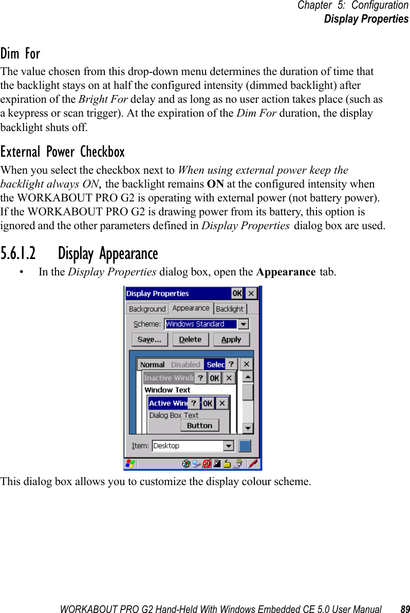
![Chapter 5: ConfigurationThe Control Panel82 WORKABOUT PRO G2 Hand-Held With Windows Embedded CE 5.0 User ManualNote: If you are uncertain how to move around a dialog box and make selec-tions, review “Using A Dialog Box” on page 72.When the WORKABOUT PRO G2 boots up, the startup desktop (shell) is displayed, and any applications stored in the Startup folder start up immediately. To access the Control Panel:• Tap on Start>Settings>Control Panel.If you’re using the keyboard:• Press [FN/BLUE] [.] to display the Start Menu.• Highlight Settings in Start Menu, and press the [RIGHT] arrow key to highlight the Control Panel.• Press the [ENTER] key.The Control Panel folder contains icons used in the setup of your WORKABOUT PRO G2.Figure 5.1 Control Panel](https://usermanual.wiki/Psion/7527BHC.Guide/User-Guide-884072-Page-90.png)
![Chapter 5: ConfigurationKeyboard Properties90 WORKABOUT PRO G2 Hand-Held With Windows Embedded CE 5.0 User Manual5.6.2 Keyboard PropertiesThis icon displays the Keyboard Properties dialog box in which you can adjust the repeat rate of the keys, the intensity of the keyboard backlight and the behaviour of the [BLUE] and [ORANGE] modifier keys. This dialog box also allows you to define macro keys and Unicode characters.•In the Control Panel, choose the Keyboard icon.Figure 5.3 Choosing The Keyboard Icon5.6.2.1 Key RepeatNote: These settings apply when a key is held down continuously. •In the Keyboard Properties dialog box, open the Repeat tab.](https://usermanual.wiki/Psion/7527BHC.Guide/User-Guide-884072-Page-98.png)
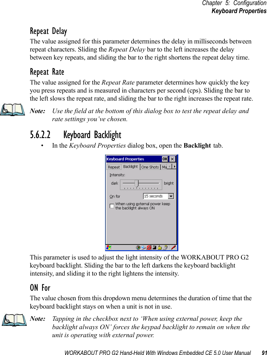
![Chapter 5: ConfigurationKeyboard Properties92 WORKABOUT PRO G2 Hand-Held With Windows Embedded CE 5.0 User Manual5.6.2.3 Keyboard One Shot Modes• In the Keyboard Properties dialog box, open the One Shots tab.The options in this tab allow you to determine how modifier keys on your WORKABOUT PRO G2 behave. For each modifier key—[ALT], [SHIFT], [CTRL], [ORANGE] and [BLUE]—you have the following options in the drop-down menu: Lock, OneShot, and OneShot/Lock. Note: Keep in mind that checking the taskbar lets you know whether or not these keys are locked on. For example, if the [FN/ORANGE] key is locked ‘on’, the taskbar at the bottom of the screen displays it in uppercase char-acters, ORANGE KEY. If this key is displayed in lowercase characters in the taskbar, you’ll know that the orange key is not locked. It will become inac-tive following a key press.Important: Once you’ve assigned a One Shot mode to a modifier key, you need to tap on the OK button at the top of the tab to activate your selec-tion.LockIf you choose Lock from the drop-down menu, pressing a modifier key once locks it ‘on’ until you press the modifier key a second time to unlock or turn it off.](https://usermanual.wiki/Psion/7527BHC.Guide/User-Guide-884072-Page-100.png)
![WORKABOUT PRO G2 Hand-Held With Windows Embedded CE 5.0 User Manual 93Chapter 5: ConfigurationKeyboard PropertiesOneShotIf you choose OneShot, the modifier key remains active only until the next key is pressed.OneShot/LockOneShot/Lock allows you to combine these functions. When you choose this option and you press the modifier key once, it remains active only until the next key is pressed. If you press the modifier key twice, it is locked ‘on’, remaining active until the modifier key is pressed a third time to turn it ‘off’.5.6.2.4 Keyboard Macro Keys•In the Keyboard Properties dialog box, open the Macros tab.A macro has 200 programmable characters (or “positions”). The macro keys can be programmed to replace frequently used keystrokes, along with the function of executable keys including [ENTER], [BKSP] and [DEL] ([FN/BLUE]-[BKSP]), function keys and arrow keys. Recording And Saving A MacroYou can program up to 12 macro keys on a 58-key WORKABOUT PRO G2. On a 36-key WORKABOUT PRO G2, you can program a maximum of 6 macro keys.•In the Macro menu highlight a macro key number, for example macro 1, to assign a macro to macro key [M1]. Choose the Record button.](https://usermanual.wiki/Psion/7527BHC.Guide/User-Guide-884072-Page-101.png)
![Chapter 5: ConfigurationKeyboard Properties94 WORKABOUT PRO G2 Hand-Held With Windows Embedded CE 5.0 User ManualA message screen is displayed instructing you to Enter Key Strokes to Record• Type the macro sequence you want to assign to the Macro key. You can type text and numbers, and you can program the function of special keys into a macro.• When you’ve finished recording your macro sequence, press the key sequence: [CTRL] [ALT] [ENTER], or choose the Stop Recording button.A new screen called ‘Verify Macro’ displays the macro sequence you created. The Save button is highlighted. • Press [ENTER] to save your macro, or highlight CANCEL and press [ENTER] to discard it.Executing A MacroTo execute a macro:• Press the macro key to which you’ve assigned the macro. For example, if you created a macro for macro key 1, press [M1] to execute the macro.Deleting A MacroTo delete a macro:•In the Macros tab, highlight the macro number you want to delete.• Choose the Delete button.](https://usermanual.wiki/Psion/7527BHC.Guide/User-Guide-884072-Page-102.png)
![WORKABOUT PRO G2 Hand-Held With Windows Embedded CE 5.0 User Manual 95Chapter 5: ConfigurationKeyboard Properties5.6.2.5 Unicode Mapping•In the Keyboard Properties dialog box, open the Unicode Mapping tab.The Unicode Mapping tab is used to map combinations of virtual key values and [CTRL] and [SHIFT] states to Unicode™ values. This tab shows the configured Unicode character along with the Unicode value. For example, the sample screen above shows “a (U+0061)” indicating that the character “a” is represented by the Unicode value “0061”, and so on. Keep in mind that Unicode configurations are represented as hexadecimal rather than decimal values.All user-defined Unicode mappings are listed in the Unicode Mapping tab in order of virtual key value, and then by order of the shift state. If a Unicode mapping is not listed, the Unicode mapping is mapped to the default Unicode value.](https://usermanual.wiki/Psion/7527BHC.Guide/User-Guide-884072-Page-103.png)
![Chapter 5: ConfigurationKeyboard Properties96 WORKABOUT PRO G2 Hand-Held With Windows Embedded CE 5.0 User ManualAdding And Changing Unicode ValuesImportant: Changes to Unicode mappings are not saved until you exit the Keyboard Properties dialog box.• Choose the Add/Change button.Figure 5.4 Adding And Change Unicode Values• Highlight a value in the Unicode mapping list. In the sample screen above, a value will be assigned to virtual key 0 (VK 0).• Position the cursor in the Unicode Mapping field, and type a Unicode value for the highlighted key.Note: To add a shifted state, [SHIFT] and/or [CTRL], press [TAB] to position the cursor in the checkbox next to ‘SHIFT Pressed’ and/or ‘CTRL Pressed’. Press [SPACE] to select the shift state you want to assign.Removing Unicode Values•In the Unicode Mapping tab, highlight the item you want to delete, and choose the Remove button.](https://usermanual.wiki/Psion/7527BHC.Guide/User-Guide-884072-Page-104.png)
![WORKABOUT PRO G2 Hand-Held With Windows Embedded CE 5.0 User Manual 97Chapter 5: ConfigurationKeyboard Properties5.6.2.6 Scancode RemappingA scancode is a number that is associated with a physical key on a keyboard. Every key has a unique scancode that is mapped to a virtual key, a function or a macro. Scancode Remapping allows you to change the functionality of any key on the keyboard. A key can be remapped to send a virtual key (e.g. VK_F represents the ‘F’ key; VK_RETURN represents the [ENTER/ON] key, etc.), perform a function (e.g. turn the scanner on, change volume/contrast, etc.) or run a macro.There are three different tables of scancode mappings: the Normal table, the Blue table and the Orange table. The Normal table defines unmodified key presses; the Blue table defines key presses that occur when the [FN/BLUE] modifier is on; the Orange table defines key presses that occur when the [FN/ORANGE] modifier is on. The default mappings of these scancodes can be overwritten for each of these three tables using the Scancode Remapping tab accessed from the Keyboard Properties dialog box.The first column in the Scancode Remapping tab displays the scancodes in hexadecimal. If the scancode is remapped to a virtual key, that virtual key is displayed in the next column labelled ‘V-Key’. A virtual key that is ‘Shifted’ or ‘Unshifted’ is displayed in the third column labelled ‘Function’. If the scancode is remapped to a function or a macro, the first and second columns remain blank while the third column contains the function name or macro key number (e.g., Macro 2).](https://usermanual.wiki/Psion/7527BHC.Guide/User-Guide-884072-Page-105.png)
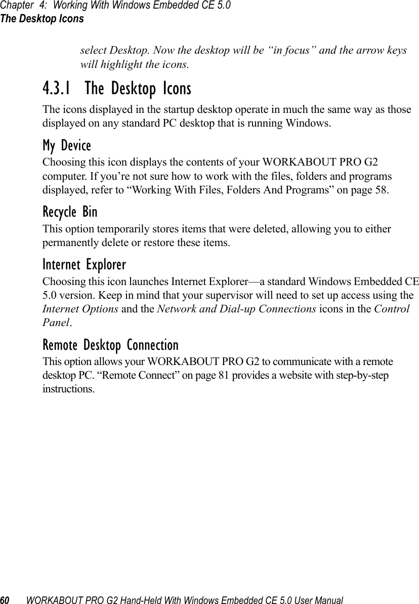
![Chapter 5: ConfigurationKeyboard Properties98 WORKABOUT PRO G2 Hand-Held With Windows Embedded CE 5.0 User ManualAdding A RemapTo add a new remapping:• Choose the Add button at the bottom of the dialog box.The Remap Scancode dialog box is displayed.• Type the scan code in hexadecimal in the field labelled ScancodeNote: The Label field displays the default function of the scancode you are remapping.Virtual Key, Function And MacroThe radio buttons at the bottom of the dialog box allow you to define to what the scan code will be remapped: Virtual Key, Function or Macro. When Virtual Key is selected, you can choose to force [SHIFT] to be on or off when the virtual key is sent. If No Force is selected, the shift state is dependent on whether the shift state is on or off at the time the virtual key is sent.When Function is selected, a list of valid functions appears in the dialog box. When Macro is selected, the macro keys available on your unit are listed in the dialog box.• Choose Virtual Key, Function or Macro.• Choose a function from the Function list in the dialog box, and tap on OK.](https://usermanual.wiki/Psion/7527BHC.Guide/User-Guide-884072-Page-106.png)
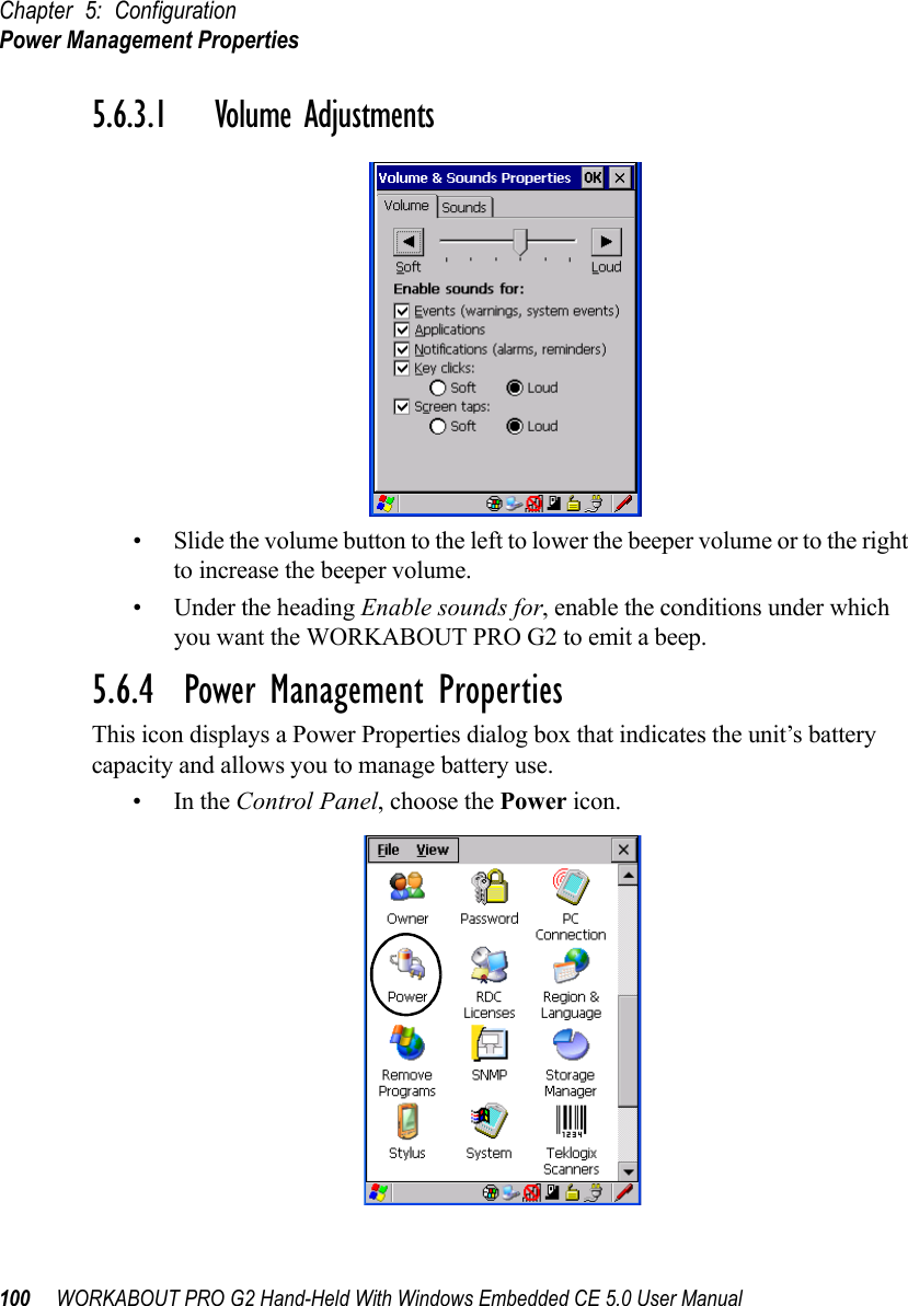
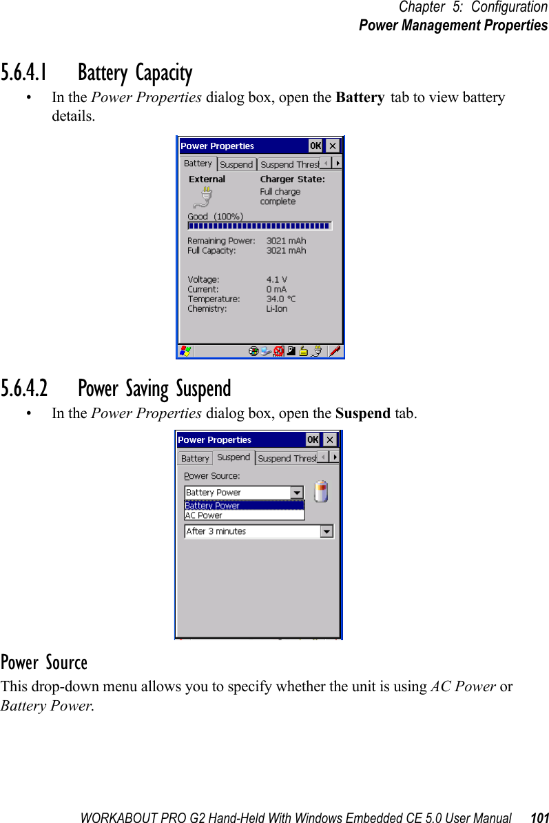
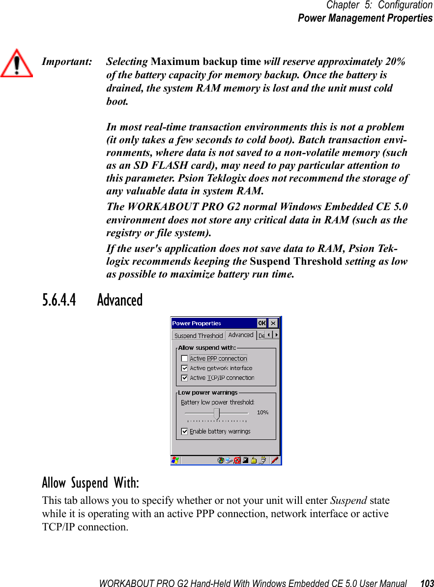
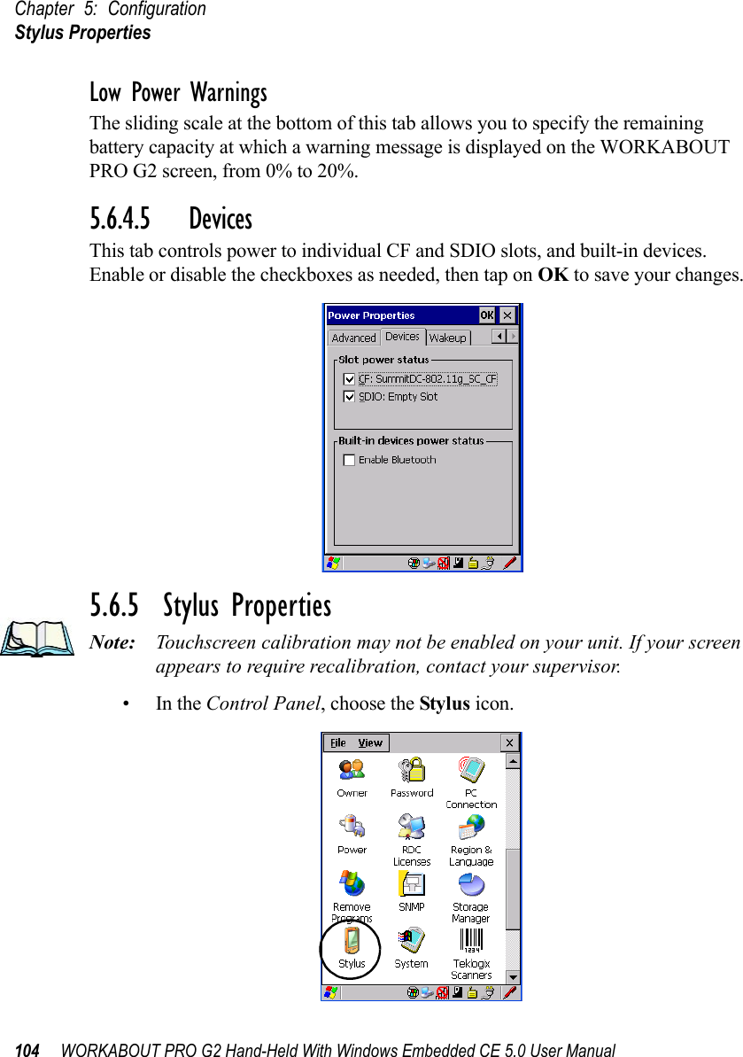
![Chapter 5: ConfigurationPower Management Properties102 WORKABOUT PRO G2 Hand-Held With Windows Embedded CE 5.0 User ManualSuspend TimeoutImportant: Psion Teklogix recommends setting the Suspend value to 10 min-utes. To further reduce power consumption, carefully consider the duration of time that the display backlight is ‘on’ (see “Display Backlight” on page 87).When the WORKABOUT PRO G2 is idle—not receiving any user input (a key touch, a scan, and so on) or system activity (serial data, an activity initiated by an application, and so on)—the hand-held uses the value assigned in the Suspend Timeout field to determine when the unit will go to sleep (appear to be off). When the time in the Suspend Timeout field elapses without any activity, the unit enters suspend state. In suspend state, the WORKABOUT PRO G2 CPU enters a sleep state, and the radio is shut off. The state of the device (RAM contents) is preserved. Pressing [ENTER] wakes the system from suspend state. When the WORKABOUT PRO G2 is in suspend state, the network connection will not be broken immediately. If the connection is dropped, you must re-establish the network connection.5.6.4.3 Suspend ThresholdThe Suspend Threshold adjustment tells the system when to shut down when the battery drains. If you choose Maximum Operating Time, the unit will run until the battery is completely empty; the RAM is only backed up for a short period of time. If you choose Maximum Backup Time, the hand-held shuts off with more energy left in the battery so RAM can be backed up for a longer period of time.](https://usermanual.wiki/Psion/7527BHC.Guide/User-Guide-884072-Page-110.png)
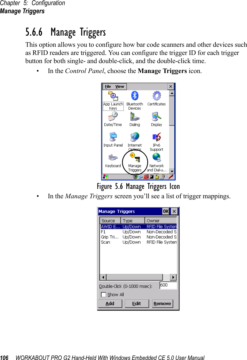
![WORKABOUT PRO G2 Hand-Held With Windows Embedded CE 5.0 User Manual 107Chapter 5: ConfigurationManage Triggers5.6.6.1 Trigger MappingsA trigger mapping is an association between a particular key on the keyboard and a driver or application, the “owner(s)” of the trigger source. When the specified key is pressed, the owner (for example, a decoded scanner) is sent a message.Important: It is not possible to have two or more identical mappings—for example [F1] cannot be mapped to the Non-Decoded Scanner twice—even if the trigger type is different.A keyboard key that is used as a trigger source will no longer gen-erate key data, or perform its normal function. For example, if the space button is used as a trigger source, it will not be able to send space characters to applications.Double-ClickWhen a key is pressed and released, then pressed again within the configured time (between 0 to 1000 milliseconds), a double-click occurs. See also “Trigger-Press Type” on page 109.Show AllBy default, the trigger mapping list only shows active mappings. Mappings for drivers or applications that are not currently active are not normally displayed. By checking this checkbox, all mappings, both active and inactive, are displayed.AddTapping this button brings up the Add mapping dialog (see page 108), so that you can add new trigger mappings.EditTapping this button brings up the Edit mapping dialog (see page 108), so that you can edit existing trigger mappings.RemoveTapping this button removes an existing mapping.](https://usermanual.wiki/Psion/7527BHC.Guide/User-Guide-884072-Page-115.png)
![Chapter 5: ConfigurationManage Triggers108 WORKABOUT PRO G2 Hand-Held With Windows Embedded CE 5.0 User ManualOKThe OK button in the top right of the Manage Triggers screen saves all changes made. If the cancel button X is tapped instead, or the [ESC] key is pressed, all changes made will be discarded.5.6.6.2 Add And Edit Trigger MappingThese dialogs allow the user to add and edit trigger mappings. Trigger KeyThis dropdown list allows you to specify the source of the trigger events, such as the Grip Trigger, Left Scan, etc., for the trigger module selected.Notes: It is possible to map the same source to different modules (trigger con-sumers)—for example, to both the Imager and Non-Decoded Scanner. If so, both devices/operations will occur simultaneously. This is not recom-mended in most cases, especially with devices such as Imagers or RFID Readers.It is also possible to map different sources to the same module (trigger consumer)—for example, two different trigger keys can be mapped to the RFID File System.](https://usermanual.wiki/Psion/7527BHC.Guide/User-Guide-884072-Page-116.png)
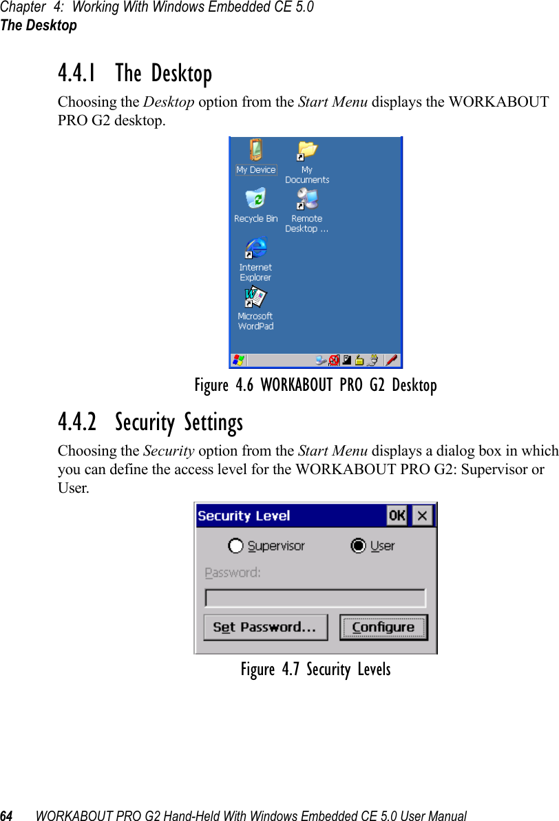
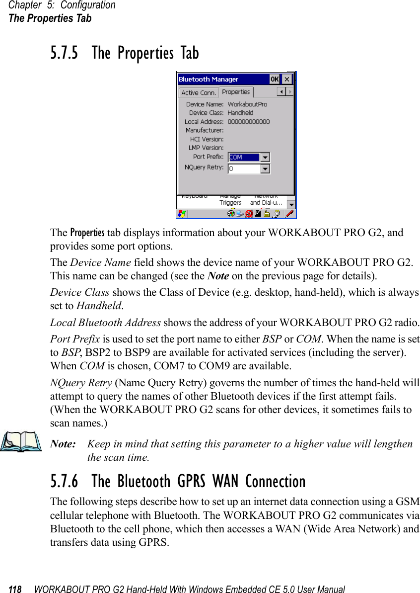
![WORKABOUT PRO G2 Hand-Held With Windows Embedded CE 5.0 User Manual 113Chapter 5: ConfigurationThe Devices TabNote: During the scanning process, addresses are located first, followed by names. Only the names of devices that are within the Bluetooth radio cov-erage range will be retrieved.The Active column indicates whether any service is activated for that device. When a service is activated, the device is displayed in the list even when it is not detected during the scan. The PIN column indicates whether you have a PIN (password) set for the device.At this point you can either query for services or set the PIN for each device. Once you highlight a device in the list box, both the Services and Set PIN buttons become available.ServicesA discovered device may display several service profiles that it can use to communicate, and you will want to activate the type you need. Supported profiles that can be activated include: DUN (Dial-Up Networking service), Printer (serial service), and LANPPP (LANAccessUsingPPP service). ASync (ActiveSync) is another available profile.• To start the service scan, highlight a device in the Devices tab list, and then click on the Services button or double-click on the device entry.Note: If the remote device is out of reach or turned off, it can take a consider-able amount of time for the Services dialog box to appear—it may appear to be frozen.Once the device’s service profiles are displayed in the Services list box:• Highlight the service to be activated.• Press [SPACE] or right-click to display the Activation menu.The Activation menu contains four options: Activate, Authenticate, Outgoing,and Encrypt.Once the service is successfully activated, the assigned port (if applicable) will appear in the Port column of the Services list box. You can choose to use BSP or COM as the port name. BSP is the latest Microsoft Bluetooth stack standard, but older applications assume serial ports are COM. When using COM as the port name, the Bluetooth manager will try to find and use a free port between COM7 and COM9. When using BSP as the port name, BSP2 to BSP9 are available for use. The port is available as soon as it is activated.](https://usermanual.wiki/Psion/7527BHC.Guide/User-Guide-884072-Page-121.png)
![Chapter 5: ConfigurationThe Devices Tab114 WORKABOUT PRO G2 Hand-Held With Windows Embedded CE 5.0 User ManualNote: The CH column shows the RFCOMM channel of the service if the service is RFCOMM-based. This information is not generally needed except for debugging purposes.To add a service to the Outgoing port, an active service must first be deactivated. Then you can choose the ‘Outgoing’ option from the Activation menu (highlight a service, right-click or press the [SPACE] bar to display the Activation menu).The Authentication and Encryption options can be changed only before activation. To change these after activation, deactivate the service first, then change the options.Once a service is activated, all the information regarding the service, including the RFCOMM channel number, is saved in the registry. (Some remote devices may change their RFCOMM channel numbers when they reboot, so your saved setting may not work when the remote device is rebooted. In that case, you must deactivate the service and reactivate it to detect the current RFCOMM channel.) Set PINPINs can be set for each device by pressing the Set PIN button in the Devices tab, or you can skip this step and try to connect to the device first. Important: The remote device must have authentication enabled, otherwise the PIN authentication will fail.• Highlight a device, click on the Set Pin button, and type the PIN.You will receive a message, either that the PIN has been successfully validated or that it has been rejected.If the PIN has been validated, an asterisk (*) appears in the PIN column in the Devices list box, indicating that this device has a PIN set. Once a PIN is entered, it is saved in the registry.To remove the PIN:• Choose Set PIN, and press [ENTER].If the WORKABOUT PRO G2 attempts to connect to a remote device that has Authentication enabled and does not have a required PIN set, an Authentication Request dialogbox appears. • Enter the PIN, and tap on OK to connect the devices.](https://usermanual.wiki/Psion/7527BHC.Guide/User-Guide-884072-Page-122.png)
![Chapter 5: ConfigurationOutgoing Tab116 WORKABOUT PRO G2 Hand-Held With Windows Embedded CE 5.0 User Manual5.7.3 Outgoing TabOutgoing Port acts as a serial port that can be used to connect to a list of Bluetooth devices (one at a time), but you have the freedom to switch on-the-fly.The Outgoing Port checkbox allows you to create the Outgoing port. When the port is created, the Outgoing tab lists the port name.The Outgoing list dialog box displays a list of services marked as ‘Outgoing’. The * column indicates the currently selected service. You can tap on Unselect to reset the current selection, or you can tap on Select to make a selection. The Remove button deletes the service from the outgoing list.The Prompt menu determines the behaviour of the pop-up Selection menu. Choosing Everytime causes the Selection menu to be displayed each time an outgoing port is created. If you choose Once, the menu is displayed only when a partner service is not selected.To display the Selection menu at any time:• Press [CTRL] [ALT] [F1], and switch the partner Bluetooth device. If a connection to a partner device already exists, the connection is dropped and another connection to the newly selected device is created instantly without disrupting the application that has opened the outgoing port.Note: To add a service to the Outgoing port, an active service must first be deactivated. Then you can choose the ‘Outgoing’ option from the Activa-tion menu (highlight a service, right-click or press the [SPACE] bar to display the Activation menu).](https://usermanual.wiki/Psion/7527BHC.Guide/User-Guide-884072-Page-124.png)
![WORKABOUT PRO G2 Hand-Held With Windows Embedded CE 5.0 User Manual 121Chapter 5: ConfigurationThe Bluetooth GPRS WAN ConnectionThe WORKABOUT PRO G2 communicates via Bluetooth to your Blue-tooth-equipped cellular telephone and retrieves the parameters for the Device Properties dialog box. The WORKABOUT PRO G2 then discon-nects.6. Under the Call Options tab, turn off Cancel the call if not connected within, and press [ENTER] to save your changes.](https://usermanual.wiki/Psion/7527BHC.Guide/User-Guide-884072-Page-129.png)
![WORKABOUT PRO G2 Hand-Held With Windows Embedded CE 5.0 User Manual 123Chapter 5: ConfigurationThe Bluetooth GPRS WAN ConnectionOnce you’ve edited this dialog box to reflect your network carrier require-ments, press [ENTER] to save your changes.10. At this point, you’ll need to return to the Control Panel, and choose the Network and Dial-up Connections icon.11. In the network connection window, the new network configuration, in this case GPRS Network is displayed. Tap on the new icon.When you tap on your new connection, an onscreen message indicates the status of your connection: connected, disconnected, error messages, and so on.](https://usermanual.wiki/Psion/7527BHC.Guide/User-Guide-884072-Page-131.png)
![Chapter 5: ConfigurationDecoded (Internal) Scanners140 WORKABOUT PRO G2 Hand-Held With Windows Embedded CE 5.0 User ManualRaster Height And Raster Expand RateThese parameter determine the laser pattern’s height and rate of expansion.Note: These parameters are only used when either Programmable Raster or Always Raster is assigned to the “2D Scanning Mode” parameter. “2D Raster Height” and “2D Raster Expand Rate” are intended for very specific applications and are usually not required for normal scanning purposes.Double-tapping on this parameter displays a dialog box in which you can enter a value from 1 to 15.5.11.2.4 Decoded (Internal) 2D Scanning OptionsTransmit Code ID CharA code ID character identifies the scanned bar code type. In addition to any single character prefix already selected, the code ID character is inserted between the prefix and the decoded symbol.When you double-tap on this parameter, a dialog box is displayed in which you can choose a transmit code: None, AIM or Symbol.Scan Data FormatThis parameter allows you to change the scan data transmission format. Double-tapping on “Scan Data Format” displays the following options from which you can choose a data format: data (as-is), data [S1], data [S2], data [S1][S2], [P] data, [P] data [S1], [P] data [S2] and [P] data [S1][S2].Prefix [P], Suffix [S1] And Suffix [S2]A prefix and/or one or two suffixes may be appended to scan data for use in data editing.When you double-tap on these parameters, a dialog box is displayed in which you can enter a value from 0 to 255.Delete Char Set ECIsSetting this parameter to on enables the scanner to delete any escape sequences representing Character Set ECIs – Extended Channel Interpretations (also known as GLIs) from its buffer before transmission.](https://usermanual.wiki/Psion/7527BHC.Guide/User-Guide-884072-Page-148.png)
![WORKABOUT PRO G2 Hand-Held With Windows Embedded CE 5.0 User Manual 145Chapter 5: ConfigurationDecoded (Internal) ScannersSuffix CharThis character, if non-zero, is added after a successfully decoded bar code. Press the key you want to insert in the dialog box attached to this parameter. The ASCII/Unicode key value of the keypress is displayed.Strip LeadingThis parameter determines the number of characters that will be removed from the beginning of the bar code before the prefix character is added.Note: The appended character is treated as any other keyboard character. For example, if [BKSP] is pressed, the usual action for that keyis performed.Strip TrailingThe value entered in this parameter determines the number of characters that will be removed from the end of the bar code before the suffix character is added.5.11.2.8 EAN 8EnabledSet this parameter to ON to enable “EAN 8”.EAN-8 Zero ExtendWhen this parameter is enabled, five leading zeros are added to decoded EAN-8 symbols, making them compatible in format to EAN-13 symbols. Disabling this parameter returns EAN-8 symbols to their normal format.Prefix/SuffixSee “Prefix/Suffix” beginning on page 144.5.11.2.9 UPC AEnabledSet this parameter to ON to enable “UPC A”.UPC-A, Check DigitIf you enable this parameter, the check digit is included with the decoded bar code data.](https://usermanual.wiki/Psion/7527BHC.Guide/User-Guide-884072-Page-153.png)
![WORKABOUT PRO G2 Hand-Held With Windows Embedded CE 5.0 User Manual 153Chapter 5: ConfigurationDecoded (Internal) ScannersEnable CC-C And Enable CC-ABTo activate these components, set these parameters to on.Enable TLC-39This composite component integrates MicroPDF417 with the linear code. Setting this parameter to on enables this parameter.5.11.2.19 PDF-417EnableSetting this parameter to on enables PDF-417 two dimensional (2D) coding.Field Size/CharRefer to page 143 for details.5.11.2.20 Micro PDF-417EnableSetting this parameter to on enables “Micro PDF-417” bar code scanning. Micro PDF-417 is a multi-row symbology that is useful for applications requiring greater area efficiency but lower data capacity than PDF-417.Code 128 EmulationWhen this parameter is enabled, the scanner transmits data from certain Micro PDF-417 symbols as if it was encoded in Code 128 symbols. If Code 128 Emulation is enabled, the following Micro PDF-417 symbols are transmitted with one of the following prefixes:]C1if the first codeword is 903-907, 912, 914, 915]C2if the first codeword is 908 or 909]C0if the first codeword is 910 or 911If Code 128 Emulation is set to off, the Micro PDF-417 symbols are transmitted with one of the following prefixes:]L3if the first codeword is 903-907, 912, 914, 915]L4if the first codeword is 908 or 909]L5if the first codeword is 910 or 911](https://usermanual.wiki/Psion/7527BHC.Guide/User-Guide-884072-Page-161.png)
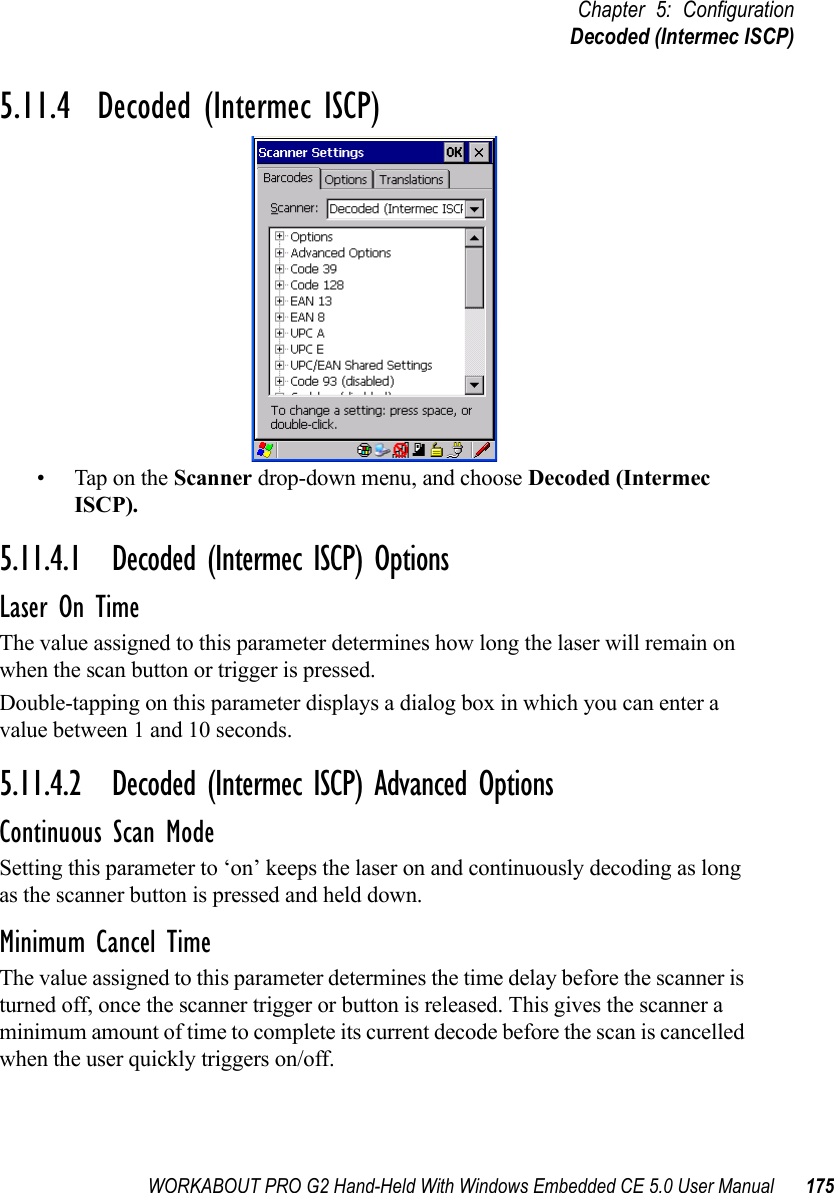
![Chapter 5: ConfigurationDecoded (Intermec ISCP)178 WORKABOUT PRO G2 Hand-Held With Windows Embedded CE 5.0 User Manual5.11.4.4 Code 128EnableSetting this parameter to on enables “Code 128”.GS1-128“GS1-128” is the GS1 implementation of the Code 128 barcode specification. The former correct name was UCC/EAN-128.GS1-128 Identifier“GS1-128 Identifier” allows the AIM ID " ]C1" for EAN 128 to be transmitted or removed. By default, this identifier is transmitted if EAN 128 is enabled.GTIN CompliantGTIN (global trade item number) processing transmits EAN 128 as the 14-character EAN/UCC GTIN. To use GTIN processing, you must activate the EAN 128 symbology.Important: When EAN 128 and GTIN processing are both activated, it is not possible to read normal EAN 128 Codes. FNC1 Conversion“FNC1 Conversion” allows the embedded FNC1 character to be converted to another character for applications that cannot use the default <GS> Group Separator or hex (1d). Double-tapping on this option displays a dialog box listing the allowable range – 0 to 255. Enable ISBT 128 To successfully scan this type of bar code (International Society of Blood Transfusion), this option must be set to on. If you enable this type of bar code, Code 128/EAN 128 is deactivated to avoid any confusion.ISBT Concat TransmitThe codes are not concatenated by default. You need to choose one of the options provided for this parameter to send concatenated code. Choosing Only Concatenated Codes transmits only concatenated codes—single codes will not be](https://usermanual.wiki/Psion/7527BHC.Guide/User-Guide-884072-Page-186.png)
![WORKABOUT PRO G2 Hand-Held With Windows Embedded CE 5.0 User Manual 189Chapter 5: ConfigurationDecoded (Intermec ISCP)Field Size/CharRefer to page 143 for details.5.11.4.19 PDF-417EnabledSet this parameter to on to enable “PDF-417”.Field Size/CharRefer to page 143 for details.5.11.4.20 Micro PDF-417EnabledSet this parameter to on to enable “Micro PDF-417”.Code 128 EmulationWhen this parameter is enabled, the scanner transmits data from certain Micro PDF-417 symbols as if it was encoded in Code 128 symbols. If Code 128 Emulation is enabled, the following Micro PDF-417 symbols are transmitted with one of the following prefixes:]C1if the first codeword is 903-907, 912, 914, 915]C2if the first codeword is 908 or 909]C0if the first codeword is 910 or 911If Code 128 Emulation is set to off, the Micro PDF-417 symbols are transmitted with one of the following prefixes:]L3if the first codeword is 903-907, 912, 914, 915]L4if the first codeword is 908 or 909]L5if the first codeword is 910 or 911Field Size/CharRefer to page 143 for details.](https://usermanual.wiki/Psion/7527BHC.Guide/User-Guide-884072-Page-197.png)
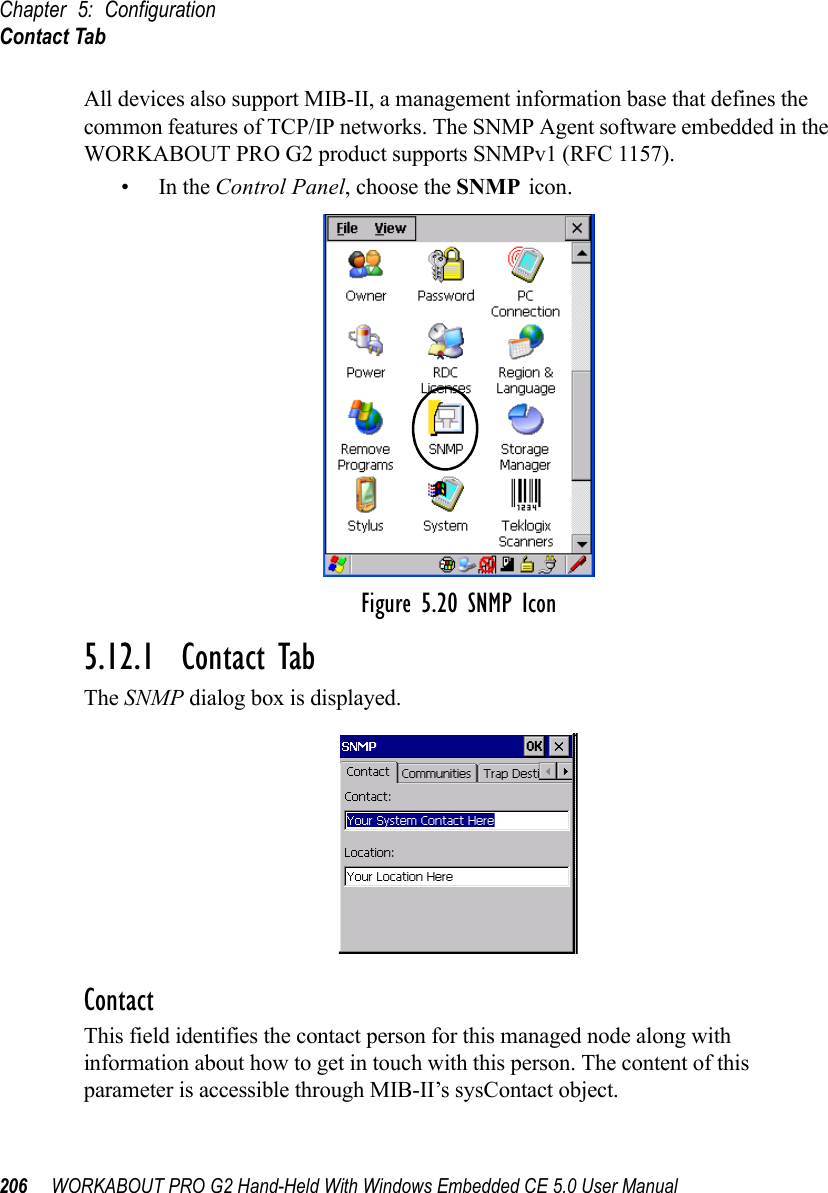
![Chapter 5: ConfigurationCommunities Tab208 WORKABOUT PRO G2 Hand-Held With Windows Embedded CE 5.0 User ManualNameThe value assigned here is the name assigned by the network administrator to the set of devices to which this managed node belongs.RightsThis menu allows you to specify access, that is, ‘Read-Only’ or ‘Read-Write’5.12.2.2 Modifying A Community SettingTo modify an existing community:• Highlight the community you want to alter.• Choose the Change button.A Modify Community dialog box is displayed, listing the community you highlighted.•Edit the Name and/or Rights, and press [ENTER] to save your changes.5.12.2.3 Removing An Existing CommunityTo remove an item:• Highlight the community you want to remove in the Communities tab and then choose the Remove button.A Delete Confirmation screen is displayed. • To remove a community, choose the Ye s button, orIf you decide not to remove the community, choose the No button.](https://usermanual.wiki/Psion/7527BHC.Guide/User-Guide-884072-Page-216.png)
![WORKABOUT PRO G2 Hand-Held With Windows Embedded CE 5.0 User Manual 209Chapter 5: ConfigurationTrap Destination Tab5.12.3 Trap Destination TabA trap is an unsolicited report sent to SNMP Managers by the SNMP Agent running on the managed node. This option allows you to define where the report will be sent.5.12.3.1 Enabling Authentication TRAPSEnabling Enable Authentication TRAPS allows authorization traps to be sent when a failure is detected (e.g., an SNMP message received with a bad community name).5.12.3.2 Adding A DestinationTo add a new destination:• Choose the Add button.• Type a destination IP address in the text box provided, and press [ENTER].5.12.3.3 Changing A DestinationTo change an existing trap destination:• Highlight the destination you want to alter in the Trap Destination tab, and then choose the Change button.](https://usermanual.wiki/Psion/7527BHC.Guide/User-Guide-884072-Page-217.png)
![Chapter 5: ConfigurationPermitted Hosts Tab210 WORKABOUT PRO G2 Hand-Held With Windows Embedded CE 5.0 User ManualA dialog box like the one displayed when you add a destination is displayed.• Make the changes to the destination, and press [ENTER] to save the changes.5.12.3.4 Removing A Trap DestinationTo remove a trap destination:•In the Trap Destination tab, highlight the destination you want to delete.• Choose the Remove button.A Delete Confirmation screen is displayed. • To remove a destination, choose the Ye s button, orIf you decide not to remove the destination, choose the No button.5.12.4 Permitted Hosts TabFor security reasons, the Network Administrator may want to restrict SNMP-node access to a known sub-set of SNMP Managers. This tab lists the IP addresses of all the SNMP Managers which are allowed to monitor and manage this device. If no entries are listed, the device will accept SNMP queries from any host.](https://usermanual.wiki/Psion/7527BHC.Guide/User-Guide-884072-Page-218.png)
![WORKABOUT PRO G2 Hand-Held With Windows Embedded CE 5.0 User Manual 211Chapter 5: ConfigurationPermitted Hosts Tab5.12.4.1 Adding A HostTo add a new host:• Highlight the Add button, and press [ENTER].• Type a new host IP address in the text box provided, and press [ENTER].5.12.4.2 Changing A HostTo change an existing host IP address:• Highlight the IP address you want to alter in the Permitted Hosts tab, and then choose the Change button.A dialog box like the one displayed when you add a host is displayed.• Make the necessary changes, and press [ENTER].](https://usermanual.wiki/Psion/7527BHC.Guide/User-Guide-884072-Page-219.png)


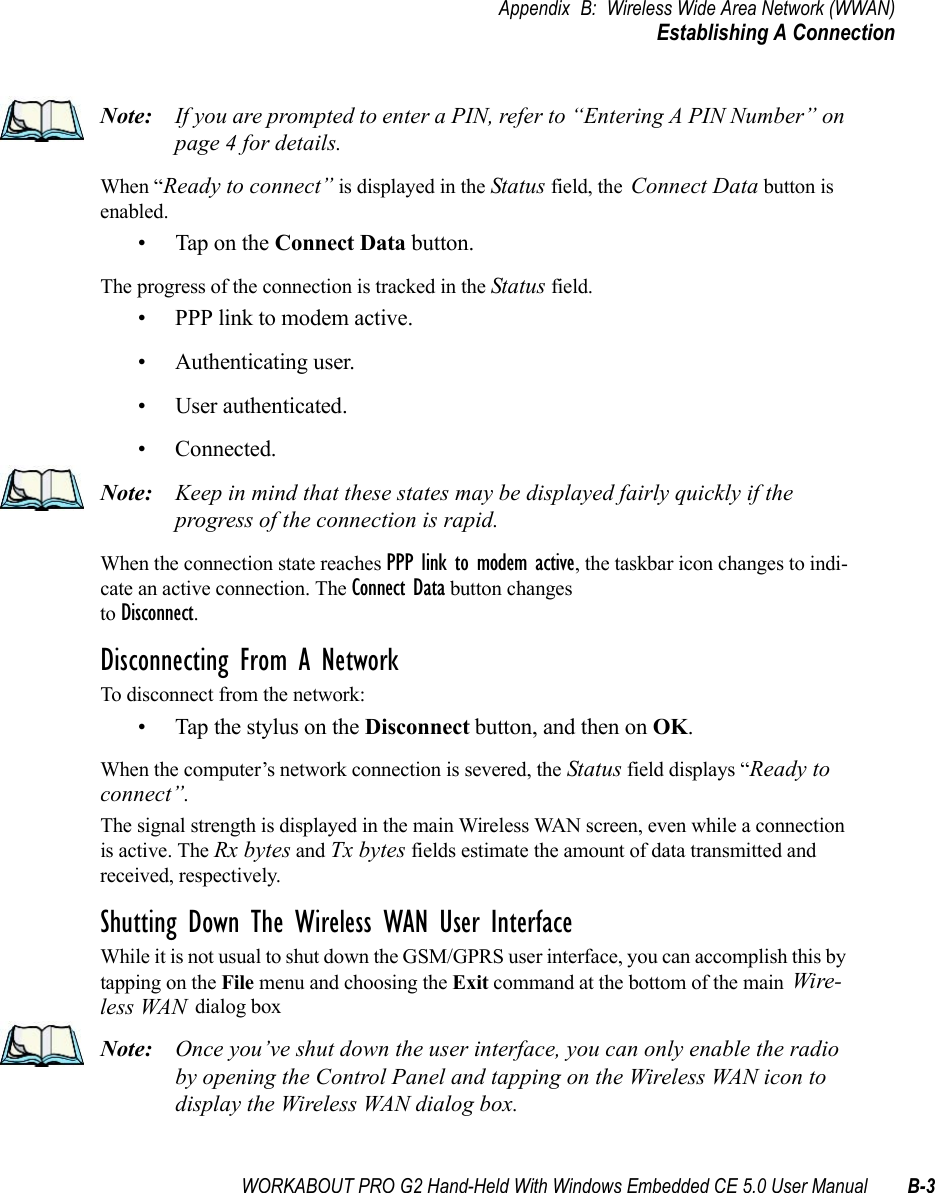
![Appendix B: Wireless Wide Area Network (WWAN)Advanced InformationB-4 WORKABOUT PRO G2 Hand-Held With Windows Embedded CE 5.0 User ManualB.1.3 Advanced InformationIn most cases, when a GSM/GPRS radio and SIM are installed in your computer, setup is automatic. Follow the steps outlined under the heading “Establishing A Connection” on page 2 to make a connection. The information in this section is for advanced setup purposes.Entering A PIN NumberIf a PIN is required, a PIN entry dialog box is displayed.• Type your PIN, and press [ENTER].Note: If you exceed the number of allowable attempts, a PUK entry window is brought to the foreground. You’ll need to enter a new PIN number.Once the correct PIN or PUK is entered or if none was required, the modem is instructed to perform a GSM network registration followed by a GPRS attach. The main Wireless WAN dialog box reflects the progress of the initialization.• Searching for modem• Initializing modem•SIM is ready• Searching for network• Registered on network• Searching for GPRS• Ready to connectIf the modem loses the connection to the GSM network, the following states are repeated: Searching for network, Registered on network, Searching for packet data, and Ready to con-nect. Error StatesThe following temporary error states (i.e., these states may disappear without interaction) may be displayed:• Emergency calls only.The modem has found a network but is not allowed to register (e.g. no roaming agreement between networks). The modem keeps searching for another network.](https://usermanual.wiki/Psion/7527BHC.Guide/User-Guide-884072-Page-266.png)