Psion 7527BSHC Handheld Computer User Manual BC01b AN 047b 17JUL01
Psion Inc Handheld Computer BC01b AN 047b 17JUL01
Psion >
Contents
users manual BT part1
bc01-an-047b
© Copyright CSR 2000
This material is subject to CSR’s non-disclosure agreement.
CSR
Unit 400 Cambridge Science Park
Milton Road
Cambridge CB4 0WH
UK
Registered in UK 3665875
Tel: +44 (0)1223 692000
Fax: +44 (0)1223 692001
http://www.csr.com
BlueCore01
BlueTest Instruction Manual
AN047
July 2001

BlueTest Instruction Manual
bc01-an-047b
© Copyright CSR Ltd 2000
This material is subject to CSR’s non-disclosure agreement
Page 2 of 56
BlueCore
TM
01
Contents
Contents...............................................................................................................................2
Introduction ..........................................................................................................................3
Getting Started Simple Tests ...............................................................................................4
Simple Tests ........................................................................................................................5
Quantitative Tests............................................................................................................... 10
Transmitter Only............................................................................................................... 10
Receiver Only................................................................................................................... 14
Loopback Test Mode ........................................................................................................ 16
Configuration Commands.................................................................................................. 22
Built-in-Self Test (BIST) Routines....................................................................................... 22
Miscellaneous Test Routines ............................................................................................. 42
Persistent Store Keys......................................................................................................... 49
Appendix 1.......................................................................................................................... 49
BIST Parameters .............................................................................................................. 49
Appendix 2.......................................................................................................................... 51
Known Software Issue(s) in BlueTest Version 1.4........................................................... 51
Appendix 3.......................................................................................................................... 52
Combining Tests Using a Second Unit ............................................................................... 52
Appendix 4.......................................................................................................................... 52
Configuration Commands Available During Tests................................................................ 53
Appendix 5.......................................................................................................................... 54
Bluetooth Packet Types .................................................................................................... 54
BlueTest Instruction Manual
bc01-an-047b
© Copyright CSR Ltd 2000
This material is subject to CSR’s non-disclosure agreement.
Page 3 of 56
BlueCore
TM
01
Introduction
BlueTest is a program that controls the
on-chip built-in-self-test (BIST) software for
RF testing. This document explains the
facilities offered by the BIST. BlueTest does
not execute any of these tests. It sends
commands to BlueCore01 and/or enables
the on-chip BIST, then reports any results.
The tests fall into six categories:
g Simple RF tests; used for PCB de-bug
and optimisation
g Quantitative tests for transmit and
receive; used to establish the
performance of the Bluetooth device.
g Loopback test modes; used for
qualification and regulatory testing
g Configuration commands to set
parameters for other tests
g Built-in self-test routines
g Miscellaneous test routines
Further details about commands,
parameters and packet types are included
in the appendices following the tests.
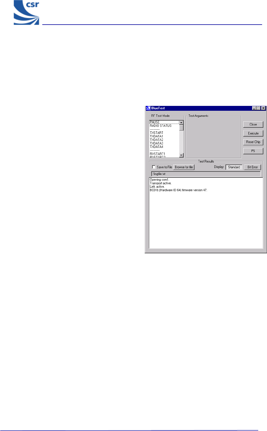
Running a Test
In a BlueTest dialog select the Standard
button to display the entire test. This applies
to all of the tests except for the BIT ERR1
and BIT ERR2 tests. Click on Bit Error to
display these results in a column format.
When running the tests, the results display in
a dialog box.
The default file name is logfile.txt. It is
located in the current directory in which the
program resides. Select Browse for File to
create your own file name and path (using
test examples provided).
To save test results to a file, tick Save to File.
Note:
Some of these tests require two
Bluetooth modules to function correctly. The
PCM External Loopback test has notes
specifically for use with CSR’s Casira
development kit.
All of the following tests are designed to run
with CSR’s firmware versions Beta 10.4 and
above.
Several tests include entries for Related Test
Spec Name. These refer to tests in the
Bluetooth Special Interest Group (SIG) Test
Specification for RF document, rev. 0.9r,
dated 31 January 2000.
BlueTest Example Display
BlueTest Instruction Manual
bc01-an-047b
© Copyright CSR Ltd 2001
This material is subject to CSR’s non-disclosure agreement.
Page 4 of 56
BlueCoreTM01
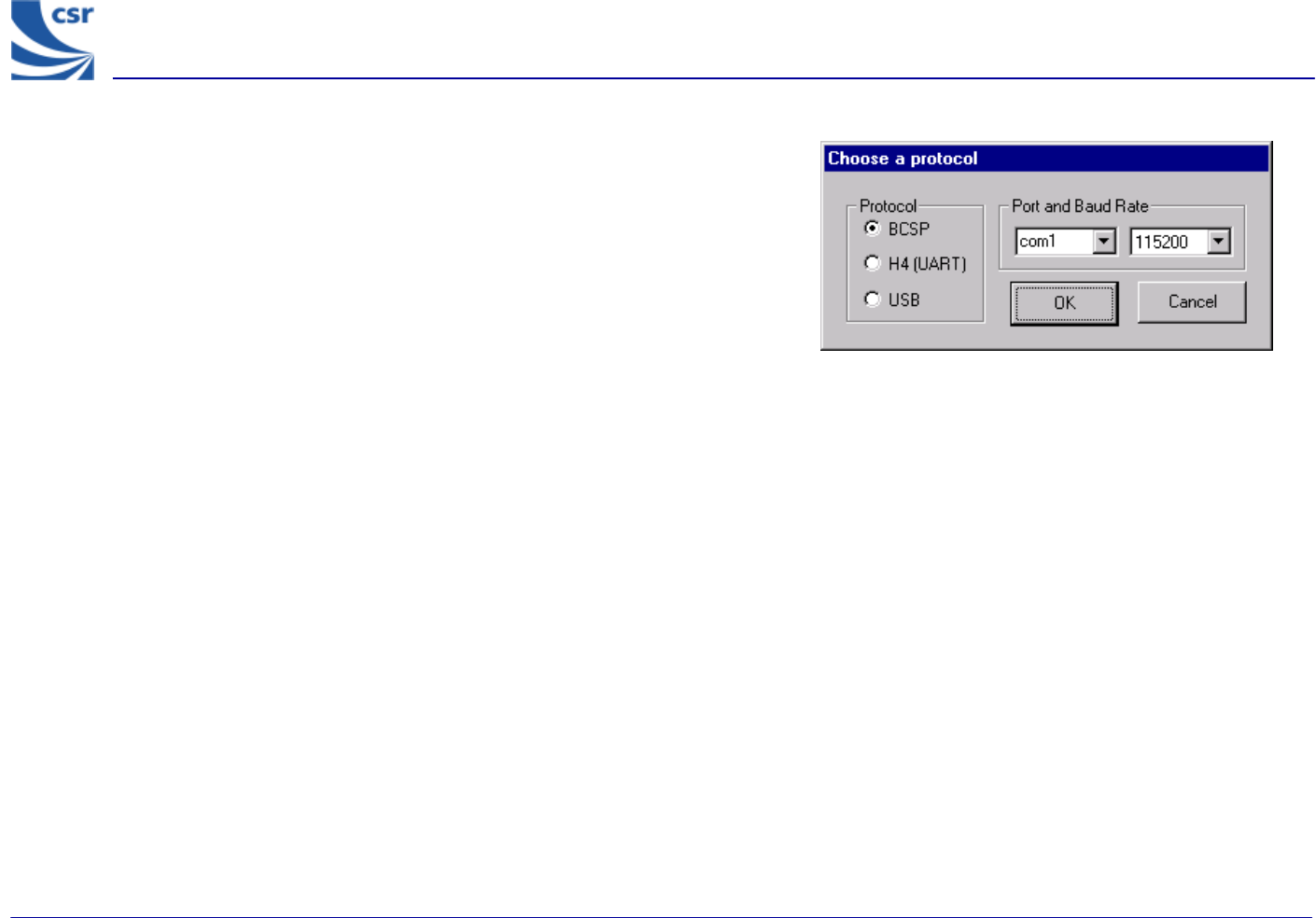
Getting Started
Run Bluetest.exe.
Select a Protocol (Default BCSP).
Select Port and Baud Rate (Default com1, 115200).
BlueTest Instruction Manual
bc01-an-047b
© Copyright CSR Ltd 2001
This material is subject to CSR’s non-disclosure agreement.
Page 5 of 56
BlueCoreTM01
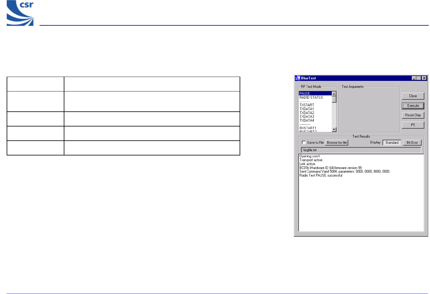
Simple Tests
RF Test Mode
Title PAUSE
Summary Halts the current test and stops any radio activity.
Test Arguments None
Return Data None
Exit Click on Reset Chip or enter a new command.
PAUSE Example Display
BlueTest Instruction Manual
bc01-an-047b
© Copyright CSR Ltd 2001
This material is subject to CSR’s non-disclosure agreement.
Page 6 of 56
BlueCoreTM01
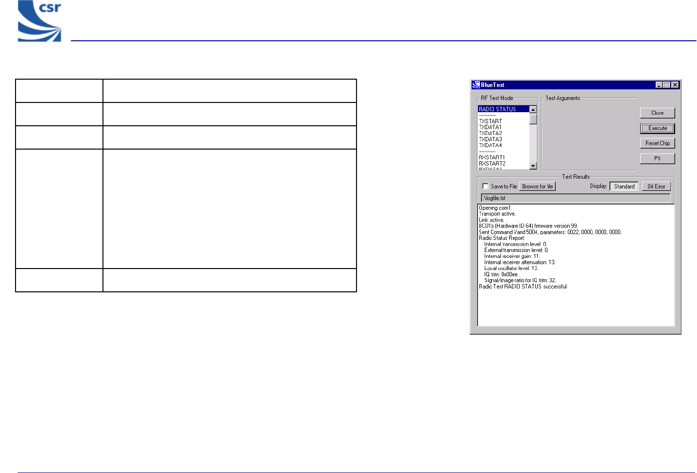
RADIO STATUS Example Display
Title RADIO STATUS
Summary Returns the values from the radio control registers.
Test Arguments None
Return Data
Internal transmission level
External transmission level
Internal receiver gain
Internal receiver attenuation
Local oscillator level
IQ trim
Signal/image ratio for IQ trim
Exit Click on Reset Chip.
BlueTest Instruction Manual
bc01-an-047b
© Copyright CSR Ltd 2001
This material is subject to CSR’s non-disclosure agreement.
Page 7 of 56
BlueCoreTM01
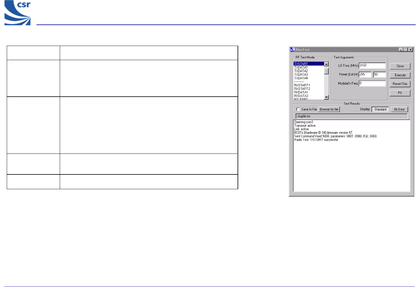
Title TXSTART
Summary
Enables the transmitter in continuous transmission at a
designated frequency (LO Freq) with a designated output Power
(Ext, Int) and designated tone modulation frequency (Modulat’n
Freq).
Test Arguments
LO Freq (Carrier Frequency in MHz) = 2402 to 2480
Power (Ext, Int) = gain of external amplifier (if present) and internal
amplifier. Ext value is specific to the design and Int value is 0 to
63 (Default = 50)
Modulat’n Freq = -32768 to 32767 in units of 1/4096MHz
Return Data None
Use RF Analyser to check carrier output.
Exit Click on Reset Chip.
TXSTART Example Display
BlueTest Instruction Manual
bc01-an-047b
© Copyright CSR Ltd 2001
This material is subject to CSR’s non-disclosure agreement.
Page 8 of 56
BlueCoreTM01
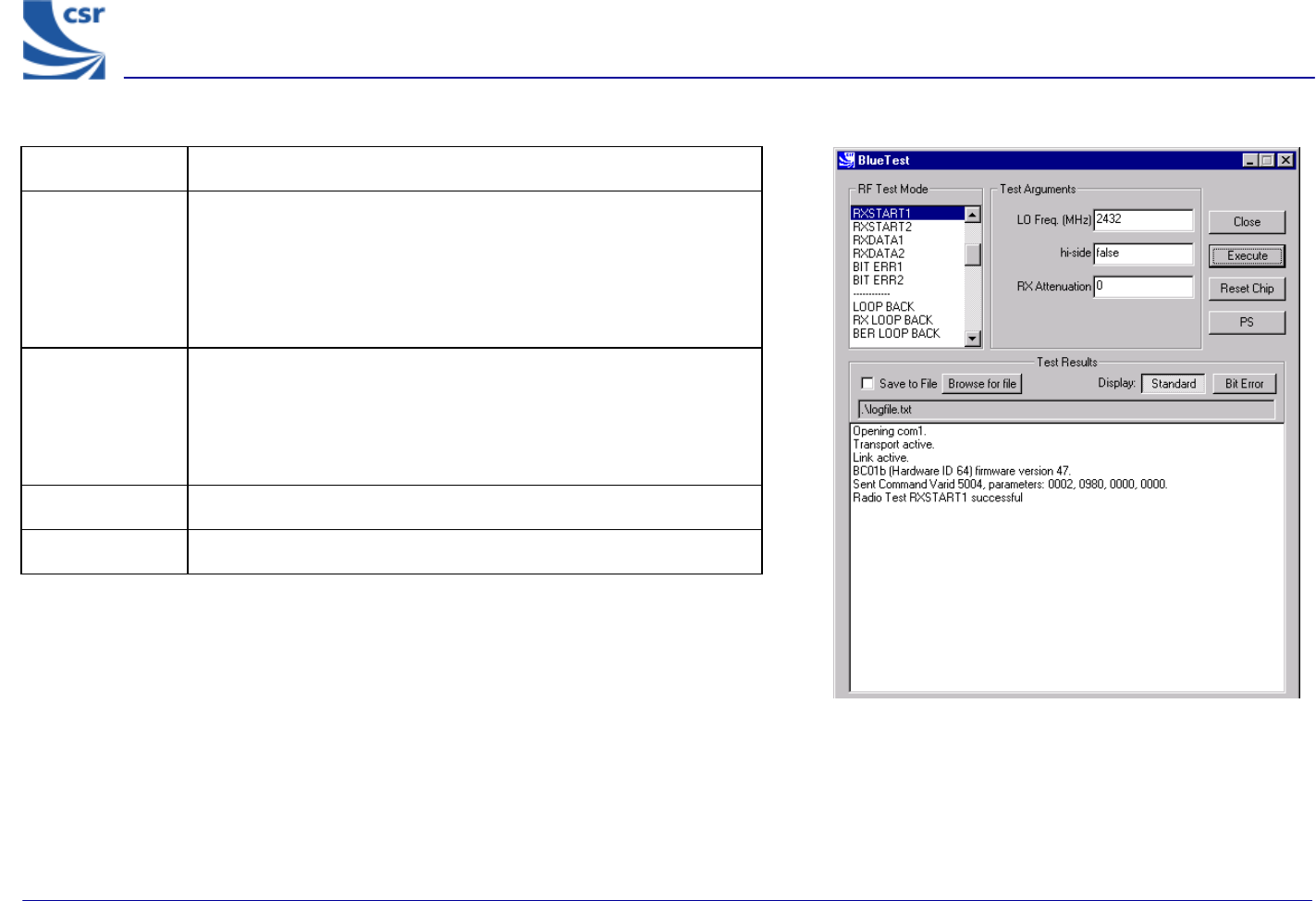
Title RXSTART1
Summary
Enables the receiver in continuous reception at a designated
frequency (LO Freq) with a choice of low or high side modulation
(hi-side) and with a designated attenuation setting (RX
Attenuation). Requires a second unit to be running TXSTART.
Routes final IF to TEST_A pin.
Test Arguments
LO Freq (Carrier Frequency MHz)= 2402 to 2480
hi-side (default = False) set 0 or 1
RX Attenuation = 0 to 15 (Default = 0)
Return Data None
Exit Click on Reset Chip.
RXSTART1 Example Display
BlueTest Instruction Manual
bc01-an-047b
© Copyright CSR Ltd 2001
This material is subject to CSR’s non-disclosure agreement.
Page 9 of 56
BlueCoreTM01
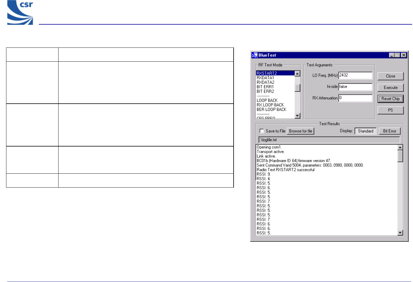
Title RXSTART2
Summary
Enables the receiver in continuous reception, at a designated
frequency (LO Freq), with a choice of low or high side
modulation (hi-side) and with a designated attenuation setting
(RX Attenuation). Digitises the RSSI and sends report regularly to
host. Requires a second unit to be running TXSTART.
Test Arguments
LO Freq (Carrier Frequency MHz) = 2402 to 2480
hi-side (default = false) set 0 or 1
RX Attenuation = 0 to 15 (Default = 0)
Return Data RSSI values, as a uint16, sent over BCSP channel 3 at a rate of
about 10 per second. Can be saved to log file. H4 and USB use
manufacturer’s extensions.
Exit Click on Reset Chip.
RXSTART2 Example Display
BlueTest Instruction Manual
bc01-an-047b
© Copyright CSR Ltd 2001
This material is subject to CSR’s non-disclosure agreement.
Page 10 of 56
BlueCoreTM01
Quantitative Tests
Transmitter Only
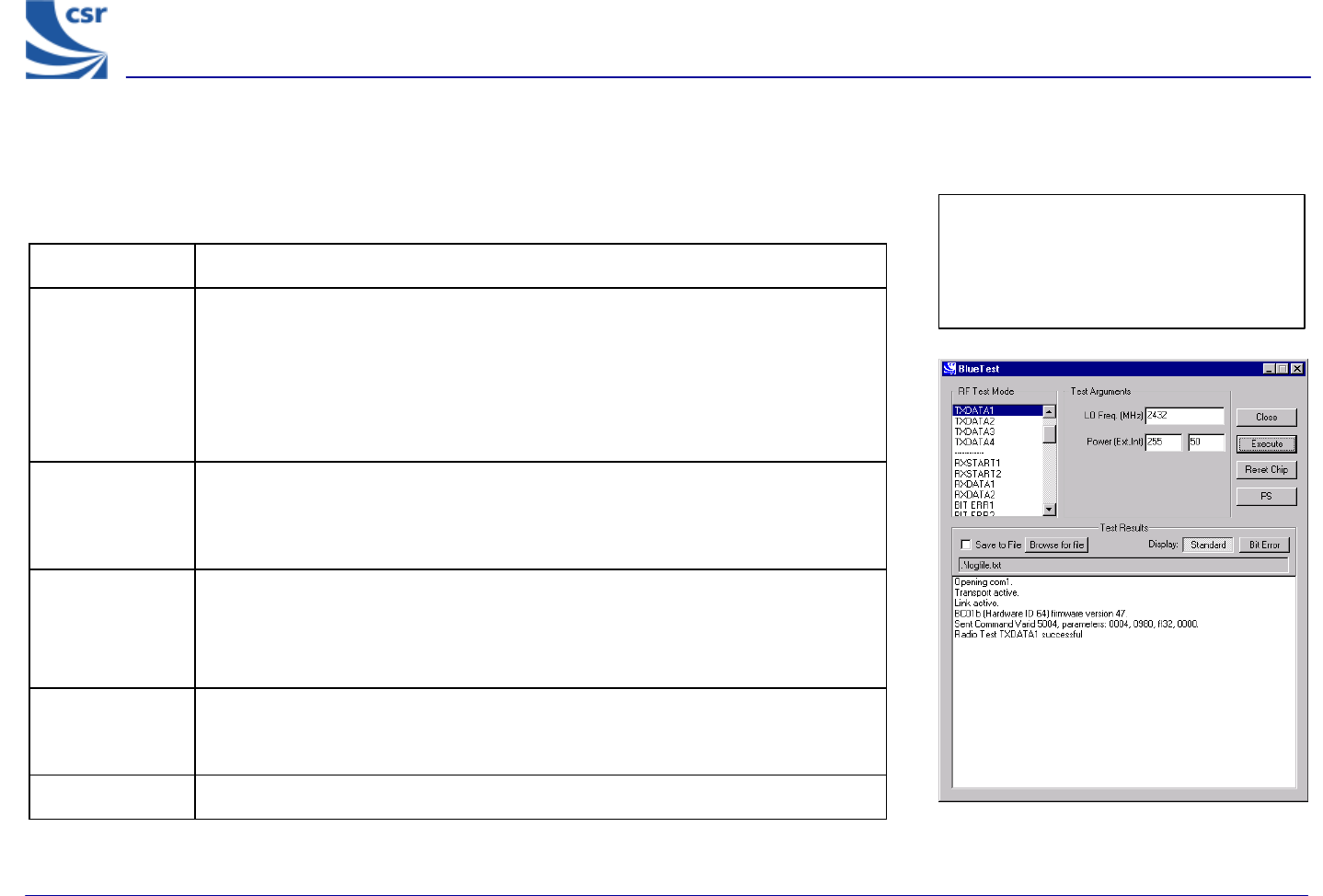
Title TXDATA1
Summary
Enables the transmitter, with a designated frequency (LO Freq) and output Power
(Ext, Int).
Payload is PRBS9 data.
Receiver is not operating.
Packet type and duty cycle can be configured. Refer to Configuration Commands
section.
Related Test
Spec Name
TRM/CA/03/C (power control), TRM/CA/04/C (Tx output spectrum – frequency
range), TRM/CA/05/C (Tx output spectrum – 20dB bandwidth), TRM/CA/06/C
(Adjacent channel power), TRM/CA/08/C (Initial carrier frequency tolerance),
TRC/CA/01/C (Out -of-band spurious emissions).
Test Arguments
LO Freq (Carrier Frequency MHz)= 2402 to 2480
Power (Ext, Int) = gain of external amplifier (if present) and internal amplifier. Ext
value is specific to the design and Int value is 0 to 63 (Default = 50).
Return Data None
Use an RF Analyser to check carrier output.
Exit Click on Reset Chip or select another TXDATA command.
TXDATA1 Example Display
BlueCoreTM01
Quantitative Tests
Transmitter Only
Note: TXDATA and RXDATA require the
same Bluetooth address in each module
for RXDATA to receive data transmitted
by TXDATA. Use CFG_UAP_LAP to set
the address used by the BIST.
BlueTest Instruction Manual
bc01-an-047b
© Copyright CSR Ltd 2001
This material is subject to CSR’s non-disclosure agreement.
Page 11 of 56
BlueCoreTM01
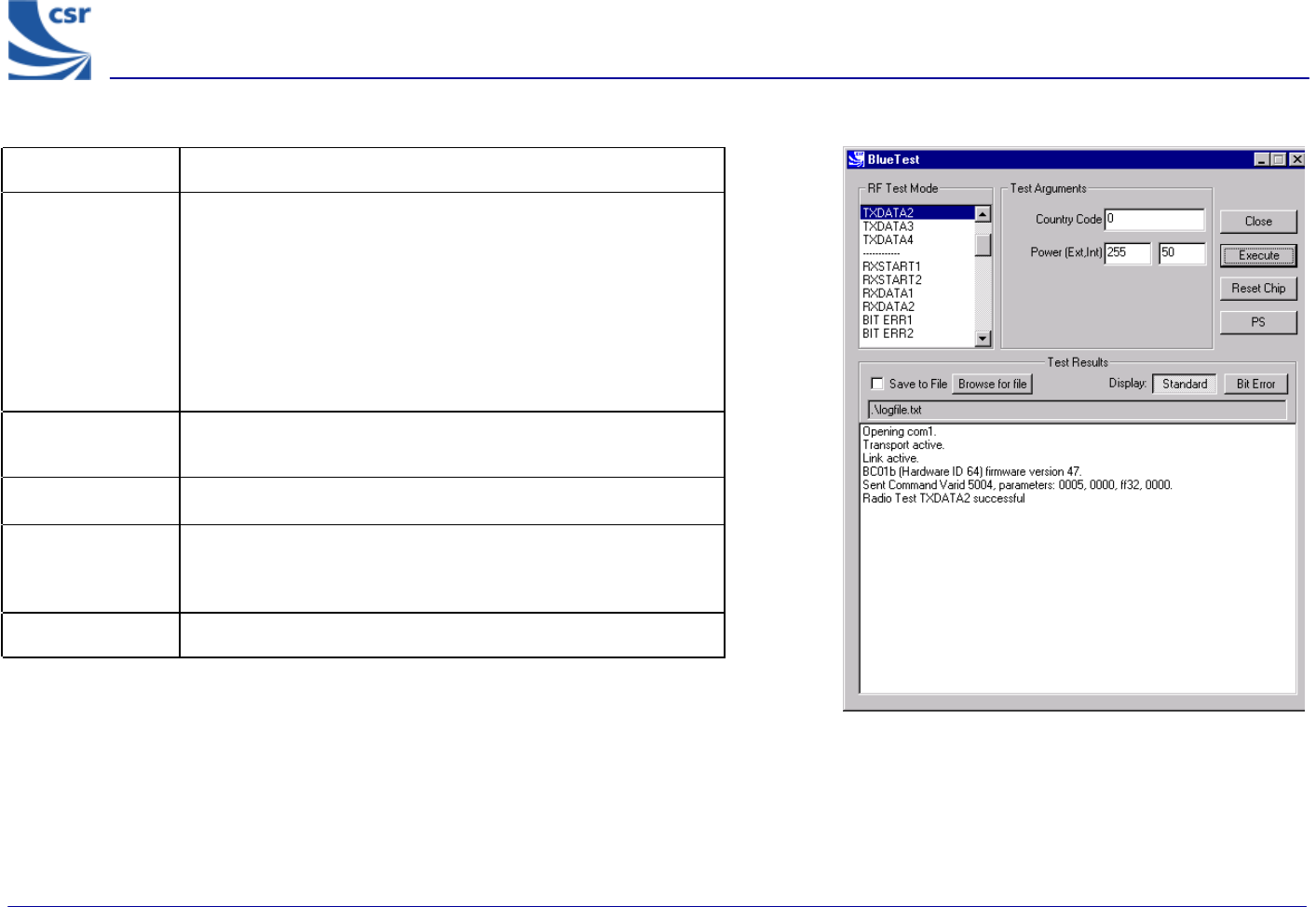
TXDATA2 Example Display
Title TXDATA2
Summary
Enables the transmitter, with a simplified hop sequence
designated by Country Code and sets output Power (Ext, Int).
Payload is PRBS9 data (Default DH1).
Receiver is not operating.
Packet type and duty cycle can be configured. Refer to
Configuration Commands section.
Related Test
Spec Name TRM/CA/01/C (output power), TRM/CA/02/C (power density)
Test Arguments Country Code = 0 to 3 (Default = 0)
Return Data None
Use RF Analyser to check carrier output.
Exit Click on Reset Chip or select another TXDATA command.
BlueTest Instruction Manual
bc01-an-047b
© Copyright CSR Ltd 2001
This material is subject to CSR’s non-disclosure agreement.
Page 12 of 56
BlueCoreTM01
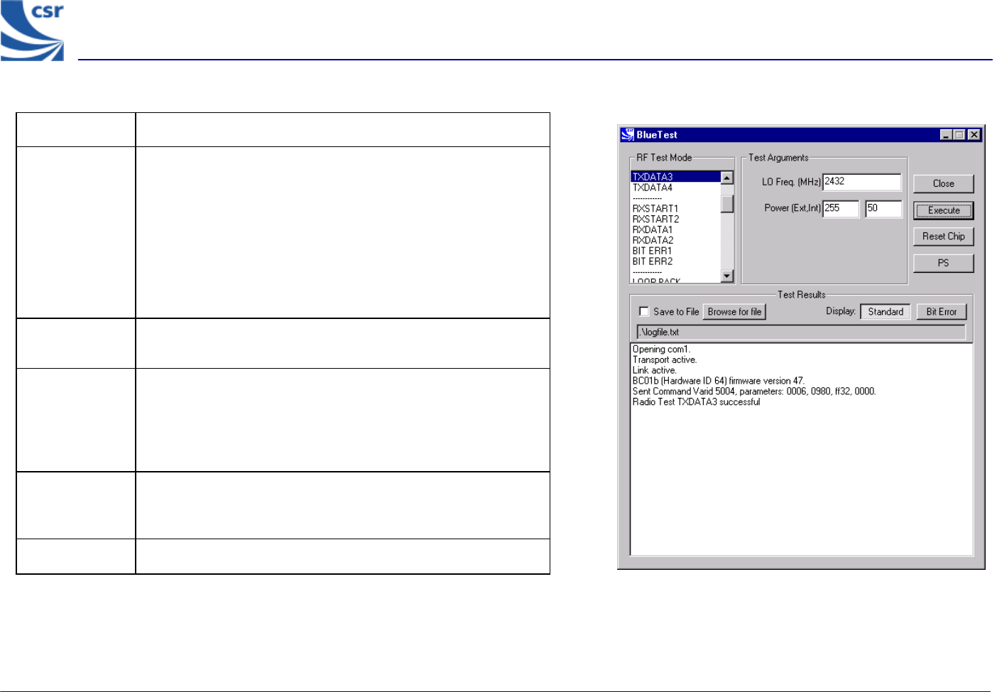
Title TXDATA3
Summary
Enables the transmitter, with a designated frequency (LO
Freq) and output Power (Ext, Int).
Payload is sequence 101010.…
Receiver is not operating.
Packet type and duty cycle can be configured. Refer to
Configuration Commands section.
Related Test
Spec Name TRM/CA/07/C (modulation characteristic), TRM/CA/09/C
(carrier frequency drift)
Test
Arguments
LO Freq (Carrier Frequency MHz)= 2402 to 2480
Power (Ext, Int) = gain of external amplifier (if present) and
internal amplifier. Ext value is specific to the design and Int
value is 0 to 63 (Default = 50).
Return Data None
Use RF Analyser to check out carrier
Exit Click on Reset Chip or select another TXDATA command.
TXDATA3 Example Display
BlueTest Instruction Manual
bc01-an-047b
© Copyright CSR Ltd 2001
This material is subject to CSR’s non-disclosure agreement.
Page 13 of 56
BlueCore
TM
01
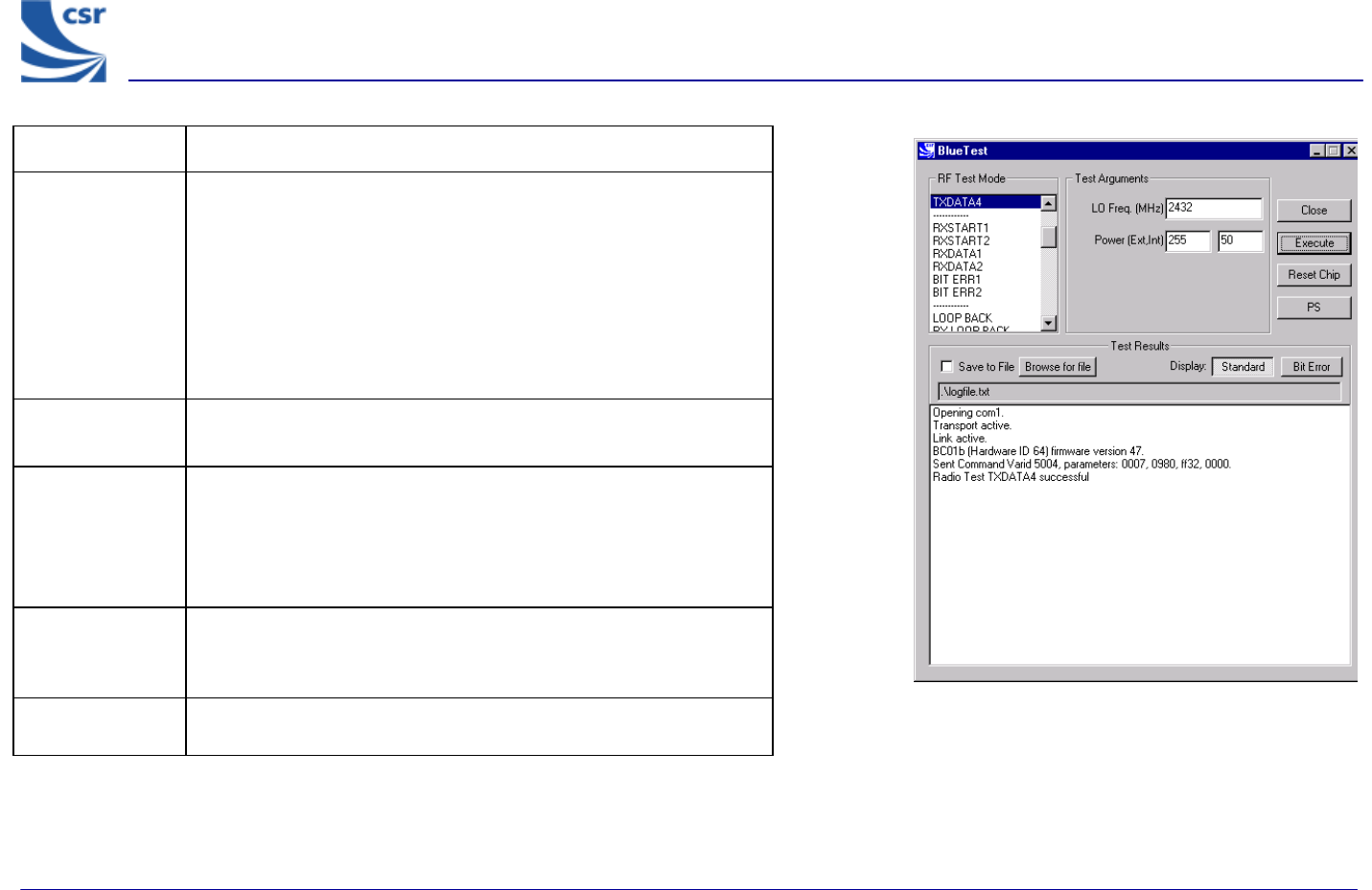
Title TXDATA4
Summary
Enables the transmitter with a designated frequency (LO Freq) and
output Power (Ext, Int).
Payload is sequence 1111000011110000.…
Receiver is not operating.
Packet type and duty cycle can be configured. Refer to
Configuration Commands section.
Related Test
Spec Name TRM/CA/07/C (modulation characteristic), TRM/CA/09/C (carrier
frequency drift)
Test Arguments
LO Freq (Carrier Frequency MHz) = 2402 to 2480
Power (Ext, Int) = gain of external amplifier (if present) and internal
amplifier. Ext value is specific to the design and Int value is 0 to
63 (Default = 50).
Return Data None
Use an RF Analyser to check out carrier.
Exit Click on Reset Chip or select another TXDATA command.
TXDATA4 Example Display
BlueTest Instruction Manual
bc01-an-047b
© Copyright CSR Ltd 2001
This material is subject to CSR’s non-disclosure agreement.
Page 14 of 56
BlueCore
TM
01
Receiver Only
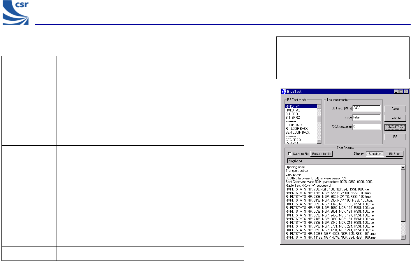
Title RXDATA1
Summary Enables the receiver, at a designated frequency (LO Freq) with a
choice of low or high side modulation (hi-side), and with a designated
attenuation setting (RX Attenuation).
The software counts the number of received packet and the number
of payloads with correctable errors.
The payload itself is thrown away. The time between receive slots and
report frequency can be set. Refer to Configuration Commands
section.
Test Arguments LO Freq (Carrier Frequency MHz)= 2402 to 2480
hi-side = 0 or 1 (default = 0)
RX Attenuation = 0 to 15 (default = 0)
Return data NP = number of packets
NP = number of good packets,
NCP = number of corrected packets
RSSI = value as shown
True = RSSI is reliable, otherwise false
The numbers wrap, rather than being reset to 0.
Exit Click on Reset Chip. RXDATA1 example display
Note: TXDATA and RXDATA require the same
Bluetooth address in each module for RXDATA
to receive data transmitted by TXDATA. Use
CFG_UAP_LAP to set the address used by the
BIST.
BlueTest Instruction Manual
bc01-an-047b
© Copyright CSR Ltd 2001
This material is subject to CSR’s non-disclosure agreement.
Page 15 of 56
BlueCore
TM
01
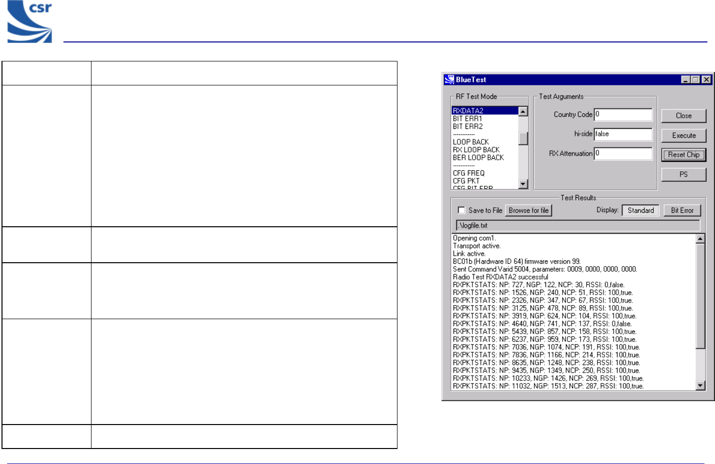
Title RXDATA2
Summary
Enables the receiver with a simplified hop sequence designated
by Country Code, with a choice of low or high side modulation
(hi-side) and with a designated attenuation setting (RX
Attenuation).
The software counts the number of received packets and the
number of payloads with correctable errors.
The payload itself is thrown away. The time between receive slots
and report frequency can be set. Refer to Configuration
Commands Section.
Related Test
Spec Name Standby mode spurious emissions (FCC test)
Test Arguments
Country Code = 0 to 3 (default = 0)
hi-side = 0 or 1 (default = 0)
RX Attenuation = 0 to 15 (default = 0)
Return Data
NP = number of packets
NG = number of good packets
NCP = number of corrected packets
RSSI = value as shown
True = RSSI is reliable, otherwise false
The numbers wrap, rather than being reset to 0.
Exit Click on Reset Chip.
RXDATA2 Example Display
BlueTest Instruction Manual
bc01-an-047b
© Copyright CSR Ltd 2001
This material is subject to CSR’s non-disclosure agreement.
Page 16 of 56
BlueCore
TM
01
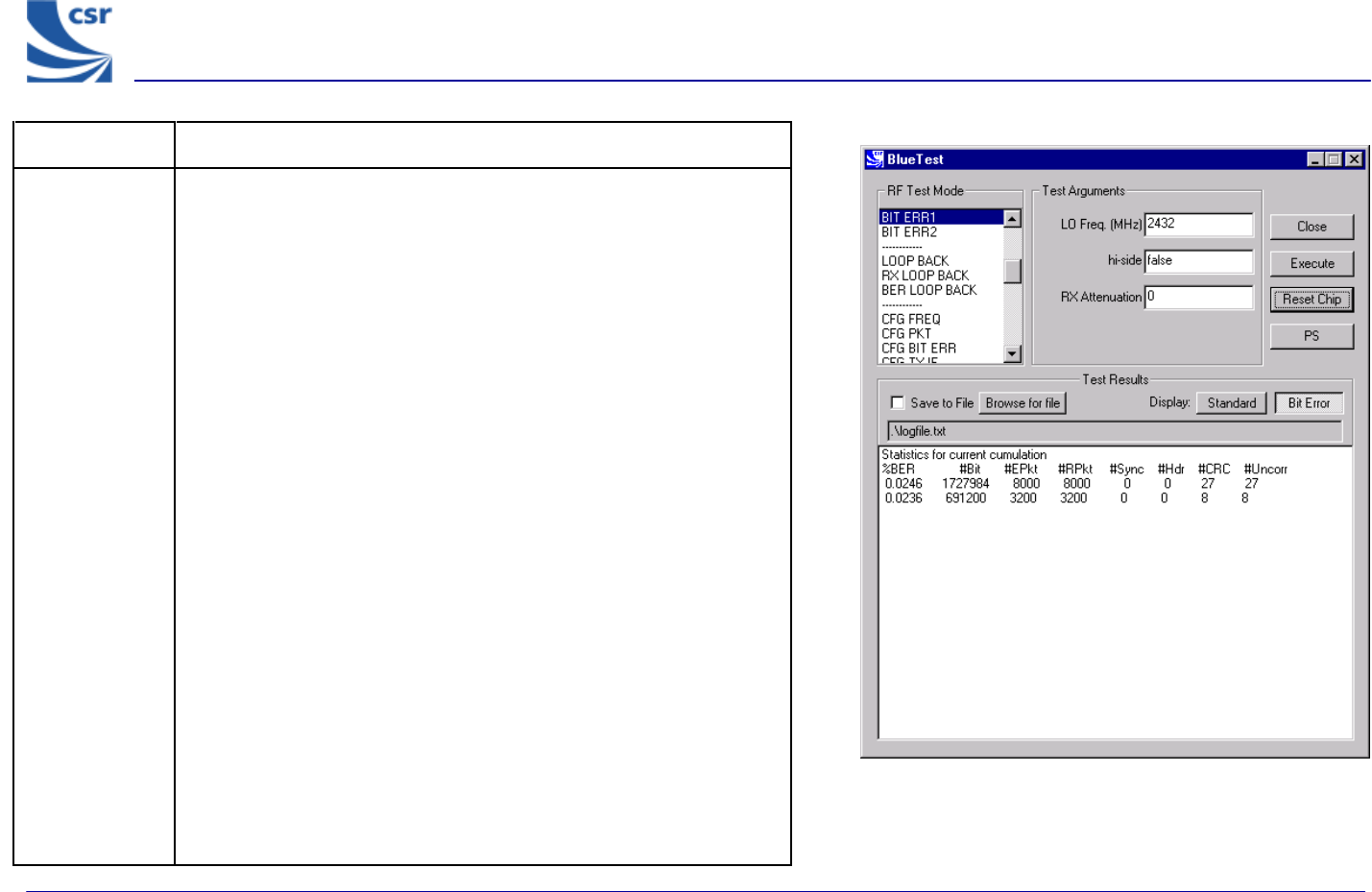
Title BIT ERR1
Summary
Enables the receiver at a designated frequency (LO Freq) with a
choice of low or high side modulation (hi-side) and with a designated
attenuation setting (RX Attenuation).
Returns a set of reports to the host:
g Number of data bits received (payload excluding FEC and CRC)
g Number of data bits that were in error. Assumes PRBS9 data
starting with 1FF in each packet
g Number of packets received
g Number of packets expected, based on txrx_freq (default
12500)
g Number of packets with header errors as reported by hardware
g Number of packets with CRC errors
g Number of packets with uncorrected errors (currently same as
CRC errors)
g Number of sync timeouts. Note that until a transmission is
received a long timeout is used, so this does not reflect the
number of packets expected
Each report has two unint32 values. First is value since last report,
second is summed over the last bits_count (default =
1.6Mbits).
Reports are sent according to report_freq set (default = 1
second). The times between receive slots and report frequency can
be set, and the count reset. Refer to Configuration Commands
section.
BIT ERR1 Example Display
BlueTest Instruction Manual
bc01-an-047b
© Copyright CSR Ltd 2001
This material is subject to CSR’s non-disclosure agreement.
Page 17 of 56
BlueCore
TM
01
Title BIT ERR1 (Continued)
Related Test Spec
Name
RCV/CA/01/C and RCV/CA/02/C (sensitivity), RCV/CA/03/C (C/I
performance), RCV/CA/04/C (blocking performance), RCV/CA/05/C
(intermodulation performance), RCV/CA/06/C (maximum input level)
Test Arguments
LO Freq (Carrier Frequency MHz) = 2402 to 2480
hi-side = 0 or 1 (default = 0)
RX Attenuation = 0 to 15 (default = 0)
Note With a second unit, execute CFG UAP/LAP to set the Bluetooth address.
Execute TXDATA1 then execute CFG UAP/LAP to set the same Bluetooth
address on the Equipment Under Test (EUT) before executing BIT ERR1.
Return Data Eight reports, each two uint32 values (refer to BIT ERR1 Summary).
Exit Click on Reset Chip.