Psion 7527RA2041 802.11g Wireless LAN CF Card User Manual 7535 G2 Hand Held Computer
Psion Inc 802.11g Wireless LAN CF Card 7535 G2 Hand Held Computer
Psion >
Contents
- 1. Manual
- 2. Users Manual Part 1
- 3. Users Manual Part 2
Users Manual Part 1

ISO 9001 Certified
Quality Management System
WORKABOUT PRO G2
Hand-Held Computer With
Windows Embedded CE 5.0
User Manual
March 5, 2007 Part No. 8000140.A
© Copyright 2007 by Psion Teklogix Inc., Mississauga, Ontario
This document and the information it contains is the property of Psion Teklogix Inc.,
is issued in strict confidence, and is not to be reproduced or copied, in whole or in
part, except for the sole purpose of promoting the sale of Psion Teklogix manufac-
tured goods and services. Furthermore, this document is not to be used as a basis for
design, manufacture, or sub-contract, or in any manner detrimental to the interests
of Psion Teklogix Inc.
Windows® and the Windows Logo are trademarks or registered trademarks of
Microsoft Corporation in the United States and/or other countries.
All trademarks are the property of their respective holders.

WORKABOUT PRO G2 Hand-Held With Windows Embedded CE 5.0 User Manual i
TABLE OF CONTENTS
Chapter 1: Introduction
1.1 About This Manual ............................3
1.2 Text Conventions.............................4
1.3 WORKABOUT PRO G2 Features....................4
1.4 About The WORKABOUT PRO G2 Hand-Held. . . ..........7
1.4.1 The WORKABOUT PRO C G2 Hand-Held Computer .....7
Chapter 2: Basic Checkout
2.1 Preparing The WORKABOUT PRO G2 For Operation.........11
2.1.1 The Main Battery.........................11
2.1.2 The Backup Battery . .......................12
2.2 Turning The WORKABOUT PRO G2 On And Off...........12
2.2.1 Installing The Battery And Switching The Unit On........12
2.2.2 Switching The Unit Off (Suspend)................13
2.3 Calibrating The Touchscreen.......................13
2.4 Configuring Your Radio..........................13
2.4.1 Summit Client Utility (SCU) For Model RA2041 ........13
2.4.2 Assigning The IP Address.....................13
2.4.3 Name Servers Tab.........................16
2.4.4 Using The SCU To Connect To The WLAN . ..........17
2.5 SCU Tabs.................................19
2.5.1 Main Tab..............................20
2.5.2 Config Tab.............................20
2.5.3 Global Settings Tab........................26
2.5.4 Status Tab.............................29
2.5.5 Diags Tab.............................30
2.6 Checking The Scanner ..........................31
2.7 Using Microsoft® ActiveSync®.....................31
Contents
ii WORKABOUT PRO G2 Hand-Held With Windows Embedded CE 5.0 User Manual
2.8 Resetting The Hand-Held........................31
2.8.1 Performing A Warm Reset....................31
2.8.2 Performing A Cold Reset – Accessing The BooSt Menu ....32
Chapter 3: Getting To Know Your WORKABOUT PRO G2
3.1 Features Of The WORKABOUT PRO G2...............35
3.2 The Battery................................36
3.2.1 Battery Safety ..........................36
3.2.2 Removing The Battery Pack...................37
3.2.3 Charging The Battery ......................37
3.3 Switching The Hand-Held On And Off.................38
3.4 The Keyboard ..............................39
3.4.1 Modifier Keys..........................39
3.4.2 The Keys.............................40
3.4.3 Function Keys And Macro Keys.................41
3.4.4 52-Key Keyboard – Accessing Alpha Keys ...........42
3.4.5 25-Key Keyboard – Accessing Alphanumeric Keys. ......42
3.4.6 The Keypad Backlight......................44
3.5 The Display...............................44
3.5.1 Adjusting The Display Backlight ................44
3.5.2 Calibrating The Touchscreen...................45
3.6 WORKABOUT PRO G2 Indicators...................46
3.6.1 LED................................46
3.6.2 Audio Indicators.........................46
3.6.3 Onscreen Indicators .......................47
3.7 Monitoring The Battery And Maximizing Run Time..........49
3.7.1 Storing Batteries.........................50
3.8 Uploading Data In A Docking Station..................51
3.9 Bluetooth Radio.............................51
3.10The SD/MMC Card—Adding Memory.................51
3.10.1Inserting The Card........................51
3.11General Maintenance ..........................52
3.11.1Caring For The Touchscreen...................52
3.11.2Cleaning The WORKABOUT PRO G2.............52
WORKABOUT PRO G2 Hand-Held With Windows Embedded CE 5.0 User Manual iii
Contents
Chapter 4: Working With Windows Embedded CE 5.0
4.1 Navigating In Windows Embedded CE 5.0................57
4.1.1 Navigating Using A Touchscreen And Stylus...........57
4.1.2 Navigating Using The Keyboard . ................57
4.2 Working With Files, Folders And Programs...............58
4.3 The Startup Desktop............................59
4.3.1 The Desktop Icons.........................60
4.3.2 The Taskbar............................61
4.4 The Start Menu..............................63
4.4.1 The Desktop............................64
4.4.2 Security Settings..........................64
4.4.3 Programs..............................66
4.4.4 Shortcuts..............................68
4.4.5 Settings...............................69
4.4.6 Run.................................70
4.4.7 Shutdown .............................71
4.5 Using A Dialog Box............................72
Chapter 5: Configuration
5.1 Remote Connect. .............................81
5.2 The TekTerm Application.........................81
5.3 Pocket PC Compatibility.........................81
5.4 The Control Panel.............................81
5.5 Control Panel Icons............................83
5.6 Basic Setup................................87
5.6.1 Display Properties.........................87
5.6.2 Keyboard Properties . .......................90
5.6.3 Volume And Sound Properties . . ................99
5.6.4 Power Management Properties.................100
5.6.5 Stylus Properties.........................104
5.6.6 Manage Triggers.........................106
5.6.7 Certificate Assignment .....................110
5.7 Bluetooth Setup.............................111
5.7.1 The Devices Tab.........................112
5.7.2 The Servers Tab.........................115
Contents
iv WORKABOUT PRO G2 Hand-Held With Windows Embedded CE 5.0 User Manual
5.7.3 Outgoing Tab...........................116
5.7.4 Active Conn. Tab.........................117
5.7.5 The Properties Tab........................118
5.7.6 The Bluetooth GPRS WAN Connection. ............118
5.8 Total Recall ...............................124
5.8.1 Creating A Backup Profile....................125
5.8.2 Restoring A Profile........................129
5.9 The Storage Manager..........................129
5.9.1 Formatting A Memory Card...................129
5.9.2 Creating Partitions........................130
5.9.3 Partition Management......................132
5.10 IPv6 Support ...............................134
5.11Scanner Settings.............................135
5.11.1Bar Codes.............................136
5.11.2Decoded (Internal) Scanners...................137
5.11.3Decoded (HHP) .........................154
5.11.4Decoded (Intermec ISCP)....................175
5.11.5Imager..............................190
5.11.6Options..............................200
5.11.7Translations Tab.........................203
5.12SNMP (Simple Network Management Protocol) Setup.........205
5.12.1Contact Tab............................206
5.12.2Communities Tab.........................207
5.12.3Trap Destination Tab.......................209
5.12.4Permitted Hosts Tab.......................210
Chapter 6: Peripheral Devices & Accessories
6.1 Carrying Accessories ..........................215
6.1.1 Attaching The Hand Strap....................215
6.1.2 Attaching The Pistol Grip....................217
6.1.3 Protective Carrying Case.....................218
6.1.4 Soft Shell Holster.........................220
6.2 The Batteries...............................221
6.3 Chargers And Docking Stations.....................221
6.3.1 Installation–Chargers And Docking Stations ..........221
6.3.2 Power Consumption Considerations...............221
WORKABOUT PRO G2 Hand-Held With Windows Embedded CE 5.0 User Manual v
Contents
6.3.3 Operator Controls........................222
6.3.4 Important Charger Safety Instructions..............222
6.4 Desktop Docking Station........................223
6.4.1 Charging A Battery Installed In The WORKABOUT PRO G2 224
6.4.2 Charging A Spare Battery....................225
6.4.3 Battery Charge Duration.....................225
6.4.4 Charger LED Indicators.....................225
6.4.5 Troubleshooting The Charging Operation Of The Dock . . . . 225
6.4.6 Desktop Docking Station Ports.................226
6.4.7 Linking A WORKABOUT PRO G2 To A PC.........226
6.4.8 Linking A WORKABOUT PRO G2 To An Ethernet Network. 227
6.4.9 Troubleshooting The Docking Station Operations .......228
6.5 Single Battery Charger–Model #WA3001-G1 .............228
6.5.1 Inserting A Battery In The Single Battery Charger.......228
6.5.2 Battery Charge Duration.....................228
6.5.3 Charge Indicators–The LED...................229
6.6 Quad Battery Charger–Model #WA3004-G1 ..............229
6.6.1 Charging Batteries........................230
6.6.2 Battery Charge Duration.....................230
6.6.3 Charge Indicators–The LEDs..................230
6.6.4 Troubleshooting . . . ......................230
6.7 Quad Docking Station–Model #WA4004-G1..............232
6.7.1 Quad Docking Station Setup ..................232
6.7.2 Quad Indicators.........................233
6.7.3 Inserting A WORKABOUT In The Quad Docking Station. . . 233
6.7.4 Network Access.........................233
6.7.5 Battery Charging–LED Behaviour...............234
6.7.6 Troubleshooting . . . ......................234
6.8 The Vehicle Cradle...........................235
6.8.1 Vehicle Cradle Mounting Recommendations . .........235
6.8.2 Wiring Guidelines........................236
6.8.3 Using The Vehicle Cradle....................236
6.8.4 Maintaining The Vehicle Cradle ................236
6.8.5 Powered Cradle Installation In High Voltage Vehicles . . . . . 237
6.8.6 Powered Vehicle Cradle Installation ..............237
6.8.7 The Port Replicator.......................238
Contents
vi WORKABOUT PRO G2 Hand-Held With Windows Embedded CE 5.0 User Manual
6.9 Bluetooth Peripherals..........................239
Chapter 7: Specifications
7.1 WORKABOUT PRO G2........................243
7.2 Radio Specifications...........................244
7.3 Scanner Specifications..........................245
7.3.1 SE 1223HP, LR, ALR And SE 955HP Specifications......245
7.3.2 EV15 Imager Specifications...................247
7.3.3 HHP5180 Imager.........................248
7.3.4 SX5393 Imager. .........................250
Appendix A: Port Pinouts
A.1 LIF (Low Insertion Force) Port Pinout .................A-1
A.2 Tether Port Pinout . . . .........................A-2
Appendix B: Wireless Wide Area Network (WWAN)
B.1 Wireless WAN..............................B-1
B.1.1 Taskbar Icons ..........................B-1
B.1.2 Establishing A Connection. ...................B-2
B.1.3 Advanced Information......................B-4
B.1.4 Tools Menu............................B-5
B.1.5 SMS Menu...........................B-13
B.2 Power Mode..............................B-14

WORKABOUT PRO G2 Hand-Held With Windows Embedded CE 5.0 User Manual 1
INTRODUCTION 1
1.1 About This Manual...............................3
1.2 Text Conventions. . . .............................4
1.3 WORKABOUT PRO G2 Features.......................4
1.4 About The WORKABOUT PRO G2 Hand-Held...............7
1.4.1 The WORKABOUT PRO C G2 Hand-Helds..............7
WORKABOUT PRO G2 Hand-Held With Windows Embedded CE 5.0 User Manual 3
Chapter 1: Introduction
About This Manual
1.1 About This Manual
This manual describes how to configure, operate and maintain the Psion Teklogix
WORKABOUT PRO G2 hand-held computer.
Chapter 1: Introduction
provides a basic overview of the WORKABOUT PRO G2 hand-held.
Chapter 2: Basic Checkout
describes the steps required to get the WORKABOUT PRO G2 ready for oper-
ation, including setting up your RA2041 802.11b/g radio.
Chapter 3: Getting To Know Your WORKABOUT PRO G2
describes the WORKABOUT PRO G2 features and outlines how to charge and
maintain the battery. This chapter also provides a description of the keyboard,
how to navigate in Microsoft Windows Embedded CE 5.0, and so on.
Chapter 4: Working With Windows Embedded CE 5.0
describes the Microsoft Windows Embedded CE 5.0 desktop and how to use it.
This chapter also outlines the basics of moving around a Windows Embedded
CE 5.0 window, selecting and opening icons, files, folders and working with a
Windows dialog box.
Chapter 5: Configuration
describes the Windows Embedded CE 5.0 Control Panel and how to use it to
configure the WORKABOUT PRO G2, along with the scanners attached to the
hand-held, and so on.
Chapter 6: Peripheral Devices & Accessories
describes the peripherals and accessories available for your WORKABOUT
PRO G2 hand-held.
Chapter 7: Specifications
lists radio, hand-held computer and battery specifications.
Appendix A: Port Pinouts
describes the WORKABOUT PRO G2 pinouts
Appendix B: Wireless Wide Area Network (WWAN)
describes WWAN configuration information (GPRS radio model no.
RA303-G2).

Chapter 1: Introduction
Text Conventions
4WORKABOUT PRO G2 Hand-Held With Windows Embedded CE 5.0 User Manual
1.2 Text Conventions
Note: Notes highlight additional helpful information.
Important: These statements provide particularly important instructions
or additional information that is critical to the operation of
the equipment.
Warning: These statements provide critical information that may prevent
physical injury, equipment damage or data loss.
1.3 WORKABOUT PRO G2 Features
Important: For all safety, regulatory and warranty information, refer to the
‘WORKABOUT PRO Hand-Held Computer Regulatory & War-
ranty Guide’, PN 8000126.
• Processor:
• PXA270 520 MHz, 32 bit RSIC CPU.
• CPU temperature range -20° to +50° C
• Software:
• Microsoft Windows Embedded CE 5.0
• Multi-Media Chipset:
• NVIDIAGoForce 4000 Multi-Media Processor
•Real-Time Clock:
• CPU independent RTC capable of maintaining the system date and time
for at least 3 months with a fully charged backup battery
• Internal Memory:
• 128 MB M-System Flash (BOM expandable up to 512 MB)
• 128 MB SDRAM (BOM expandable up to 512 MB)
• User Accessible Memory:
• One SD expansion slot (accessible via the battery compartment)
•Display:
• 480 x 640, 3.6 in., Full VGA TFT Colour LCD
• Easily replaceable and customizable bezel
WORKABOUT PRO G2 Hand-Held With Windows Embedded CE 5.0 User Manual 5
Chapter 1: Introduction
WORKABOUT PRO G2 Features
• Keyboards:
• Alphanumeric keyboard option with 52 keys and blue backlight, or
• Numeric keyboard option with 25 keys and blue backlight
• Four, direct push function keys
• Side-Scan buttons
• Audio:
• One mono speaker
• One mono microphone
• One internal audio connector for future external audio interfaces
• Beeper capable of producing 85db @ 10cm
• Internal Connectors:
• 100-pin expansion interface; supports PCMCIA (type II), WAN and
other expansion modules
• Flex cable interface with robust connector; supports scanner (serial) and
imager (USB) modules.
• Additional USB connection at top edge of MLB (Powered from the bat-
tery; user voltage regulation required)
• One Type II CF Card Slot
• One SD Slot (memory card form factor only)
• Full pin-to-pin compatibility shall be maintained with WORKABOUT
PRO G1 series
• External Connectors “On The Go”:
• One Tether connector with full RS232 and USB OTG functionality
• Tether connection backward compatible with WORKABOUT PRO G1
series
• One LIF connection backward compatible with WORKABOUT PRO
G1 series
• DC Power Jack
• Bluetooth Radio:
• Integrated Bluetooth 1.2 radio
• Class II Compliant / Range 5 to 10 metres
• Support for 802.11b/g CF radio with non-integrated antenna
• GSM Support:
• Support for RA3030-G2 GPRS radio (connecting via the 100-pin
Expansion Connector)
Chapter 1: Introduction
WORKABOUT PRO G2 Features
6WORKABOUT PRO G2 Hand-Held With Windows Embedded CE 5.0 User Manual
• Support for GSM/GPRS/EDGE data and voice communications
• User-accessible SIM card
• 802.11b/g Support
• Support for RA2041 802.11b/g Compact Flash radio module
• Power System:
• High Capacity battery pack: Li-Ion, 3.7V, 3000mAh
• Super High Capacity battery pack: Li-Ion, 3.7V, 4000mAh
• One removable backup batter
• User-replaceable backup battery
• Dimensions and Weight:
• RS232 serial (decoded scanner, printer)
• Undecoded scanner support
• USB host
Docking station port with:
• RS232 serial with diagnostics
• USB device
• USB host
• Power in/out
• Power management:
• Typical 8-hour usage Lithium-Ion standard battery
• Quick swap packs
• Advanced smart battery with gas gauge
• Runs with battery, wall adaptor or cigarette lighter
• Built-in fast charger (2 hours)
• System backup during battery swap (more than 10 minutes)
• One week real-time clock backup
• Network Management:
• SNMP MIB 2 support
• Remote software download
• Remote WLAN management

WORKABOUT PRO G2 Hand-Held With Windows Embedded CE 5.0 User Manual 7
Chapter 1: Introduction
About The WORKABOUT PRO G2 Hand-Held
1.4 About The WORKABOUT PRO G2 Hand-Held
The WORKABOUT PRO G2 is a ruggedized hand-held personal computer,
running the Microsoft Windows Embedded CE 5.0 operating system. It is intended
for use in commercial and light industrial applications with a focus on real time
wireless data transactions. All possible bar code input methodologies are supported
by one of a variety of scanners available. Optimization for specific operational
environments is supported with a wide range of peripheral options and carrying
accessories.
1.4.1 The WORKABOUT PRO C G2 Hand-Helds
Figure 1.1 WORKABOUT PRO C G2 With 52-Key Keyboard

Chapter 1: Introduction
The WORKABOUT PRO S G2 Hand-Held
8WORKABOUT PRO G2 Hand-Held With Windows Embedded CE 5.0 User Manual
1.4.2 The WORKABOUT PRO S G2 Hand-Held
Figure 1.2 WORKABOUT PRO S G2 With 25-Key Keyboard

WORKABOUT PRO G2 Hand-Held With Windows Embedded CE 5.0 User Manual 9
BASIC CHECKOUT 2
2.1 Preparing The WORKABOUT PRO G2 For Operation . . . . . . . . . . 11
2.1.1 The Main Battery...........................11
2.1.1.1 Charging The Main Battery.................11
2.1.2 The Backup Battery. . . . . . . . . . . . . . . . . . . . . . . . . . 12
2.2 Turning The WORKABOUT PRO G2 On And Off . . . . . . . . . . . . 12
2.2.1 Installing The Battery And Switching The Unit On . . . . . . . . . 12
2.2.2 Switching The Unit Off (Suspend)..................13
2.3 Calibrating The Touchscreen........................13
2.4 Configuring The RA2041 802.11b/g Radio. . . . . . . . . . . . . . . . . 13
2.4.1 Summit Client Utility (SCU) For Model RA2041 . . . . . . . . . . 13
2.4.2 Assigning The IP Address......................13
2.4.3 Name Servers Tab ..........................16
2.4.4 Using The SCU To Connect To The WLAN.............17
2.4.4.1 SSID.............................18
2.4.4.2 EAP Type..........................18
2.4.4.3 Encryption..........................18
2.5 SCU Tabs..................................19
2.5.1 Main Tab...............................20
2.5.2 Config Tab..............................20
2.5.2.1 SCU Security Capabilities..................23
2.5.2.2 EAP Credentials.......................25
2.5.2.3 ThirdPartyConfig......................26
2.5.3 Global Settings Tab..........................26
2.5.4 Status Tab...............................29
2.5.5 Diags Tab...............................30
2.6 Checking The Scanner...........................31
2.7 Using Microsoft® ActiveSync®......................31
2.8 Resetting The Hand-Held..........................31
2.8.1 Performing A Warm Reset......................31
2.8.2 Performing A Cold Reset – Accessing The BooSt Menu . . . . . . 32
WORKABOUT PRO G2 Hand-Held With Windows Embedded CE 5.0 User Manual 11
Chapter 2: Basic Checkout
Preparing The WORKABOUT PRO G2 For Operation
2.1 Preparing The WORKABOUT PRO G2 For Operation
2.1.1 The Main Battery
Warning: Before charging the battery, it is critical that you review the battery
safety guidelines in the “WORKABOUT PRO Hand-Held Com-
puter Warranty & Regulatory Guide”, PN 8000126.
The WORKABOUT PRO C G2 and WORKABOUT PRO S G2 can be powered
with one of the following lithium-in battery packs:
• High-Capacity Battery Pack – 3000mAh
• Super High-Capacity Battery Pack – 4000mAh
2.1.1.1 Charging The Main Battery
Important: Before opening the battery cover on your WORKABOUT PRO
G2, press [BLUE] [ENTER] to turn off the hand-held. When the
battery cover is removed, a power-off switch is automatically acti-
vated and the unit power is switched off; if the battery cover is
opened while the hand-held is still powered on, the unit may
reboot.
Battery packs shipped from the factory are charged to approximately 40% and must
be fully charged prior to use. Batteries can be charged using a variety of chargers
and docking stations along with a WORKABOUT PRO G2 internal charger. When
using the internal charger, a suitable power source is required. All chargers and
docking stations are described in Chapter 6: Peripheral Devices & Accessories
beginning on page 213.
Note: If you are powering up a new unit, a warning message may appear on the
screen indicating that the backup battery capacity is low. To recharge the
internal battery, you must fully charge the WORKABOUT PRO G2 with
the main battery installed in the unit. An overnight charge is recom-
mended.

Chapter 2: Basic Checkout
The Backup Battery
12 WORKABOUT PRO G2 Hand-Held With Windows Embedded CE 5.0 User Manual
2.1.2 The Backup Battery
To preserve data stored in your WORKABOUT PRO G2 while you swap the main
battery, the unit is equipped with an internal backup battery–a standard Lithium
Alloy Manganese Dioxide coin battery–a Maxell ML2032. The backup battery will
supply 5 minutes of continuous power while you install a charged, main battery.
The backup battery is trickle charged from the main battery. Provided that the main
battery contains power, the backup battery will maintain a charge whether the
WORKABOUT PRO G2 is switched on or off, in a docking station or in a cradle.
Even when the main battery reaches its Suspend Threshold (refer to “Suspend
Threshold” on page 102) and the hand-held shuts down, the backup battery will
continue to draw a trickle charge from the main battery to protect the data stored in
the unit until a charged main battery is installed.
Note: The backup battery takes approximately 100 hrs to fully charge from a
fully discharged (flat) state. While you can continue to use the WORK-
ABOUT PRO G2, replacing the main battery while the backup battery is
not fully charged is not recommended because you risk losing the data
stored on the unit.
2.2 Turning The WORKABOUT PRO G2 On And Off
2.2.1 Installing The Battery And Switching The Unit On
• To unlock the battery cover, turn the left-hand battery fastener to the left,
and turn the right-hand battery fastener to the right. The top of the stylus is
slot-shaped to help you loosen the fasteners.
• Remove the battery cover.
• Ensure that the ON/OFF switch in the battery compartment is set to ON
before inserting the battery.
• Snap the charged battery into the unit. Replace the battery cover, and lock
the fasteners in place.
Note: If you are using a docking station or an external power supply, you can
insert an uncharged battery, dock the unit and switch it on.
To switch on the WORKABOUT PRO G2:
• Press and hold down the [ENTER/ON] key for at least one second.
• When the LED flashes green, release the [ENTER/ON] button.

WORKABOUT PRO G2 Hand-Held With Windows Embedded CE 5.0 User Manual 13
Chapter 2: Basic Checkout
Switching The Unit Off (Suspend)
The desktop screen is displayed.
Note: If the unit was already in use–the unit may be off (suspend state)–press-
ing [ENTER/ON] ‘wakes’ the unit from this state. The screen in which you
were working prior to the suspend state is displayed.
2.2.2 Switching The Unit Off (Suspend)
• Press the [BLUE] key, and then press [ENTER/ON].
2.3 Calibrating The Touchscreen
Note: Keep in mind that the touchscreen function can be turned off (see
“Touch” on page 105).
The WORKABOUT PRO G2 touchscreen is factory-calibrated and ready-to-go;
however, over time the touchscreen operating parameters may change, and it may
need to be recalibrated for correct operation. Refer to “Calibrating The
Touchscreen” on page 45 for details.
2.4 Configuring The RA2041 802.11b/g Radio
Psion Teklogix supports an 802.11b/g Compact Flash (CF) wireless LAN radio
card, model number RA2041. It is a Direct Sequence Spread Spectrum radio.
If your WORKABOUT PRO G2 is equipped with an RA2041 CF radio, follow the
steps under “Summit Client Utility (SCU) For Model RA2041” below to set up this
type of radio for communication with a wireless LAN.
2.4.1 Summit Client Utility (SCU) For Model RA2041
This section describes the Summit Client Utility (SCU). The SCU provides the
utilities you will need to configure the Summit 802.11b/g Compact Flash radio
module, model number RA2041 so that it can communicate through a wireless LAN
effectively and securely.
2.4.2 Assigning The IP Address
Before launching the SCU, you need to configure how the IP address will be
obtained. If your network is not using a DHCP server, you will need to assign an
IP address.
Chapter 2: Basic Checkout
Assigning The IP Address
14 WORKABOUT PRO G2 Hand-Held With Windows Embedded CE 5.0 User Manual
1. Tap on Start>Settings>Network and Dial-up Connections. (If the
Start Menu isn’t displayed in the taskbar, press [BLUE] [0] to display
it.)
If you’re using the keyboard, press [BLUE] [0] to display the Start Menu.
Use the [DOWN] arrow key to highlight Settings. Press the [RIGHT] arrow
key to display the sub-menu. Highlight Network, and press [ENTER].
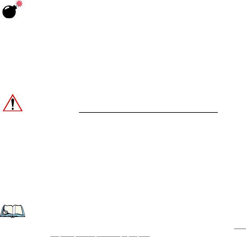
2. Choose the Summit WLAN Adapter icon to open the 802.11b/g Wire-
less LAN Settings window. In Figure 2.1, this icon is labelled
SDCCF10G1.
Figure 2.1 Summit WLAN Adapter Icon
The Summit WLAN Adapter Settings menu is displayed (In this screen
shown as the SDCCF10G1 menu).
WORKABOUT PRO G2 Hand-Held With Windows Embedded CE 5.0 User Manual 15
Chapter 2: Basic Checkout
Assigning The IP Address
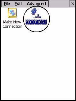
3. Tap on the IP Information tab.
Figure 2.2 IP Information Tab
Note: Choosing the Renew button forces the WORKABOUT PRO G2 to renew
or find a new IP address. This is useful if, for example, you are out of
communication range for a longer period of time and your WORK-
ABOUT PRO G2 is dropped from the network.
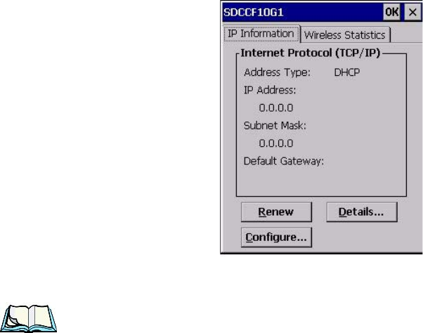
4. To define a static IP address, tap on the Configure button. The Summit
WLAN Adapter Settings menu provides two options:
• Tap on Obtain an IP address via DHCP to have an address assigned
automatically, or
• If you want to use a particular IP address, tap on Specify an IP address,
and type the preferred address as well as the IP, Subnet Mask and
Default Gateway addresses in the appropriate fields. Tap OK to save
your information.
Chapter 2: Basic Checkout
Name Servers Tab
16 WORKABOUT PRO G2 Hand-Held With Windows Embedded CE 5.0 User Manual
Figure 2.3 Defining An IP Address
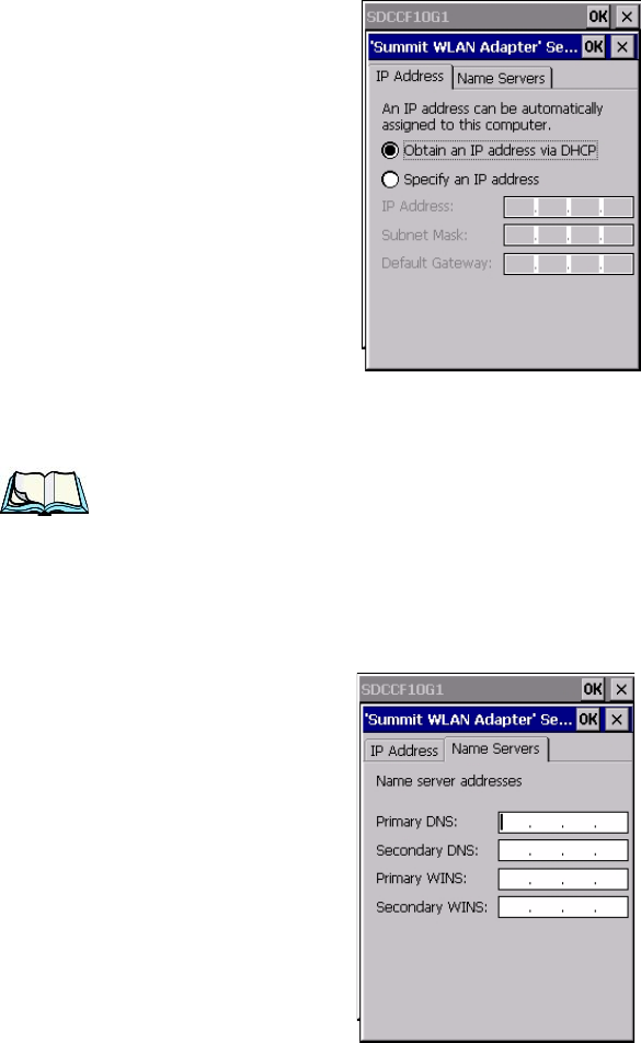
2.4.3 Name Servers Tab
Note: If DHCP is enabled, name server addresses are assigned automatically.
•In the SDCCF10G1 window, display the IP Information tab.
•In the Summit WLAN Adapter Settings>IP Information tab, tap on the
Configure button.
• Display the Name Servers tab.
Figure 2.4 Name Servers Tab
WORKABOUT PRO G2 Hand-Held With Windows Embedded CE 5.0 User Manual 17
Chapter 2: Basic Checkout
Using The SCU To Connect To The WLAN
The DNS and WINS fields in the Name Servers tab allow you to specify additional
WINS and DNS resolvers. The format for these fields is ###.###.###.###.
2.4.4 Using The SCU To Connect To The WLAN
This section provides a quick set of steps to create a profile (referred to as a
“config”). Detailed information about each of the SCU tabs—Main, Config, Status,
Diags and Global Settings—is provided under “SCU Tabs” on page 19. To launch
the SCU so that your WORKABOUT PRO G2 can connect to a wireless LAN:
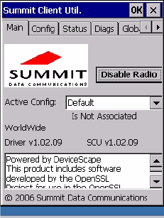
1. Tap on Start>Programs>Summit, and then tap on the SCU icon.
Figure 2.5 SCU Main Tab
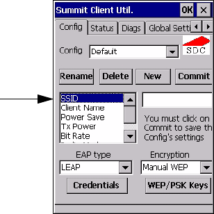
2. Tap on the Config tab.
Figure 2.6 SCU Config Tab

Chapter 2: Basic Checkout
SSID
18 WORKABOUT PRO G2 Hand-Held With Windows Embedded CE 5.0 User Manual
• Tap on the New button to define a new config.
• Type a name for your configuration using any alpha-numeric combination
to uniquely identify this config.
• Tap on OK to return to the Config tab.
• Tap on Commit to save the config name.
• When a pop-up message indicates that your configuration will be saved, tap
on OK.
2.4.4.1 SSID
To configure the SSID for the network to which you want to associate:
• Type an SSID in the text box to the right of SSID. This field is limited to 32
characters.
• Tap on Commit and then, in the pop-up message, tap on OK to save your
SSID setting.
Important: To learn more about the other options available in the radio
attributes list, refer to “Config Tab” on page 20.
2.4.4.2 EAP Type
• Tap on the EAP type drop-down menu, and choose the appropriate type of
authentication—LEAP, EAP-FAST, PEAP-MSCHAP, and PEAP-GTC.
• Next, tap on the Credentials button, and type credentials for IEEE 802.1X
EAP types.
Important: Refer to “SCU Security Capabilities” on page 23 for details about
security settings. Additional EAP details are described in “EAP
Credentials” on page 25.
2.4.4.3 Encryption
• Tap on the Encryption drop-down menu, and choose the appropriate type
of encryption—Manual WEP, Auto WEP, WPA PSK, WPA TKIP,
WAP2PSK, WAP2 AES, and CCKM TKIP.
If you choose Manual WEP, WPA PSK or WPA PSK:
• Tap on the WEP/PSK Keys button. For Manual WEP, choose up to four
static WEP keys. For PSK, type an ASCII passphrase or hex PSK.

WORKABOUT PRO G2 Hand-Held With Windows Embedded CE 5.0 User Manual 19
Chapter 2: Basic Checkout
SCU Tabs
• Configure any other settings that are supplied by the network administrator
for the SSID to which you will associate.
• Make certain that you tap on Commit following each change.
Once you’ve completed the configuration:
• Tap the Main tab. Tap on the Active Config button – your new config will
be listed in the drop-down menu.
When you tap on the config you created, the RA2041 radio module attempts to
connect to the network using the following steps:
- Associate to the SSID.
- Authenticate to the network.
- If EAP authentication is being used, derive dynamic encryption keys.
- If DHCP is being used by the network, obtain an IP address.
If the RA2041 is not connecting properly:
• Tap on the Status tab.
The Status dialog box lists the IP and MAC addresses, and indicates the current state
of the radio, the signal strength, channel and so on.
You can also use the Status screen for DHCP renewal and ICMP Echo Requests
(Pings).
Important: For details about the Status dialog box, refer to “Status Tab” on
page 29.
2.5 SCU Tabs
This section provides a detailed description of each of the tabs available in the
SCU—Main (below), Config (page 20), Global Settings (page 26), Status (page 29),
and Diags (page 30).
Chapter 2: Basic Checkout
Main Tab
20 WORKABOUT PRO G2 Hand-Held With Windows Embedded CE 5.0 User Manual
2.5.1 Main Tab
The Main tab is displayed when you tap on the Start>Programs>SCU icon.
Figure 2.7 SCU Main Tab
•Enable/Disable Radio: Enables or disables the radio. This a toggle button;
when the radio is enabled, this button reads Disable Radio, and when the
radio is disabled, the button reads Enable Radio.
•Active Config: Lists the name(s) of the active configuration profile(s)
which are referred to as “configs”. When a config is chosen from the Active
Config drop-down menu, the settings for that config become active.
If ThirdPartyConfig is selected, after the WORKABOUT PRO G2 goes
through a power cycle, WZC is used for configuration of the radio. See
“ThirdPartyConfig” on page 26 for details.
•Association Status: Indicates if the radio is associated to an access point. If
this is not the case, Association Status indicates the radio status.
•Software Version: This field displays the version of the device driver and
the SCU that are running on the WORKABOUT PRO G2.
•About Box: This box provides information about the SCU.
2.5.2 Config Tab
The Config tab allows you to define radio and security settings that are stored in the
registry as part of the configuration profile or config.
WORKABOUT PRO G2 Hand-Held With Windows Embedded CE 5.0 User Manual 21
Chapter 2: Basic Checkout
Config Tab
The config you create and save is listed in the Active Config drop-down menu in the
Main tab You can define up to 20 configs.
Figure 2.8 SCU Config Tab
•Config: Used to choose the config to be viewed or edited. If ThirdParty-
Config is chosen, after the WORKABOUT PRO G2 goes through a power
cycle, WZC is used for configuration of the radio.
•Rename: Allows you to assign a config name.
•Delete: Deletes the config unless it is currently active.
•New: Allows you to create a new config with default settings and assign it
a name.
•Commit: Saves all changes.
•Radio Attributes: Lists radio attributes. These attributes can be individu-
ally chosen from this menu. When an attribute is chosen, an associated
list of options is displayed where you can assign new settings or view
existing settings.
Radio
Attributes

Chapter 2: Basic Checkout
Config Tab
22 WORKABOUT PRO G2 Hand-Held With Windows Embedded CE 5.0 User Manual
The following table describes the options in the Radio Attributes drop-down menu:
Radio
Attribute Description Value Default
Config
Name of config (configu-
ration profile). Use
Rename button to change
name.
Maximum of 32 characters. None
SSID Service set identifier
(SSID) for WLAN to
which the radio connects. Maximum of 32 characters. None
Client
Name
Name assigned to radio &
WORKABOUT PRO G2
into which it is installed. Maximum of 16 characters. None
Power Save Power save mode for
radio.
CAM: Constantly awake.
Maximum: Maximum
power savings.
Fast: Fast power save
mode.
Fast
Tx Power Maximum transmit power.
Max: Maximum defined for
current regulatory domain.
Measured in mW: 50,30,10,
1.
Max
Bit Rate Used by radio when inter-
acting with WLAN access
point.
Auto: Rate automatically
negotiated with access
point.
Rates in Mbps: 1, 2, 5.5, 6.9
11, 12, 18, 24, 36, 48, 54.
Auto
Radio
Mode
Used by 802.11g when
interacting with access
point.
B rates only: 1, 2, 5.5, & 11
Mbps.
G rates only: 6, 9, 12, 18,
24, 36, 48, and 54 Mbps.
BG rates full: All B and G
rates.
BG rates optimized: 1, 2,
5.5, 6, 11, 24, 36 & 54
Mbps.
BG rates
opti-
mized

WORKABOUT PRO G2 Hand-Held With Windows Embedded CE 5.0 User Manual 23
Chapter 2: Basic Checkout
SCU Security Capabilities
•EAP-Type & Encryption: Security settings. These settings allow you to
enhance the security of data across the wireless LAN. Refer to “EAP Cre-
dentials” on page 25 and “SCU Security Capabilities” below, for details
about these settings.
2.5.2.1 SCU Security Capabilities
The SCU provides integrated security to protect transmitted data as well as the hand-
held and wireless WAN infrastructure that transmit and receive data.
Auth Type 802.11 authentication type
used when associating
with access point.
Open, shared-key, or LEAP
(Network-EAP). Open
EAP Type
Extensible Authentication
Protocol type used for
802.1X authentication to
access point.
None, LEAP, EAP-FAST,
PEAP-MSCHAP
– To use EAP-TLS, you
must
use WZC.
None
Credentials
Authentication credentials
for the selected EAP type.
Refer to “EAP Creden-
tials” on page 25.
User: Username or
Domain/Username (up to
64 characters).
Password: up to 64 charac-
ters.
For PEAP: CA Cert–CA
server certificate filename.
None
Encryption Type of encryption used to
protect transmitted data.
None, Manual WEP, Auto
WEP (generated during
EAP authentication), WPA
PSK, WPA TKIP, WPA2
PSK, WPA2 TKIP, WPA2
AES, CCKM TKIP.
For Manual WEP: Up to
four
static WEP keys.
For PSK: ASCII passphrase
or hex PSK.
None
Radio
Attribute Description Value Default

Chapter 2: Basic Checkout
SCU Security Capabilities
24 WORKABOUT PRO G2 Hand-Held With Windows Embedded CE 5.0 User Manual
A foundational element of the IEEE 802.11i WLAN security standard is IEEE
802.1X and a critical application on a mobile device is an 802.1X supplicant. This
supplicant provides an interface between the radio and the operating system and
supports the authentication and encryption elements required for 802.11i, also
known as Wi-Fi Protected Access 2 (WPA2), as well as predecessors such as WPA
and WEP. Summit software includes an integrated supplicant that supports a broad
range of security capabilities, including:
• 802.1X authentication using pre-shared keys or an EAP type, required for
WPA2 and WPA.
• Data encryption and decryption using WPA2 AES, WPA TKIP or WEP.
Common EAP types include:
•EAP-TLS: Uses the same technology as a follow-on to Secure Socket
Layer (SSL). It provides strong security, but relies on client certificates for
user authentication.
•PEAP: Provides secure user authentication by using a TLS tunnel to
encrypt EAP traffic. Two different inner methods are used with PEAP:
• EAP-MSCHAPV2, resulting in PEAP-MSCHAP: This is appropriate
for use against Windows Active Directory and domains.
• EAP-GTC, resulting in PEAP-GTC: This is for authentication with one-
time passwords (OTPs) against OTP databases such as SecureID.
•LEAP: Is an authentication method for use with Cisco WLAN access
points. LEAP does not require the use of server or client certificates. LEAP
supports Windows Active Directory and domains but requires the use of
strong passwords to avoid vulnerability to offline dictionary attacks.
•EAP-FAST: Is a successor to LEAP and does not require strong passwords
to protect against offline dictionary attacks. Like LEAP, EAP-FAST does
not require the use of server or client certificates and supports Windows
Active Directory and domains.
Note: PEAP and EAP-TLS require the use of Windows facilities for the configu-
ration of digital certificates.
WORKABOUT PRO G2 Hand-Held With Windows Embedded CE 5.0 User Manual 25
Chapter 2: Basic Checkout
EAP Credentials
SCU EAP Types
The following EAP types are supported by the integrated supplicant and can be
configured in SCU: PEAP-MSCHAP, PEAP-GTC, LEAP and EAP-FAST. With
each of these four types, if authentication credentials are not stored in the config,
you will be prompted to enter credentials the first time the radio attempts to
associate to an access point that supports 802.1X (EAP).
Consider the following when configuring one of the EAP types:
• PEAP-GTC: SCU supports static (login) passwords only.
• LEAP: Strong passwords are recommended.
• EAP-FAST: SCU supports automatic, not manual, PAC provisioning.
EAP-TLS will work with a RA2041 radio module when Windows Zero Config
(WZC) rather than the SCU is used to configure the type. With WZC, the native
Windows supplicant instead of the SCU integrated supplicant is used.
2.5.2.2 EAP Credentials
Keep the following in mind when defining security settings:
• If the credentials specified in the config are incorrect and that config is used,
the authentication fails without an error message; you will not be prompted
to enter correct credentials.
• If the credentials are not specified in the config, when the radio tries to asso-
ciate using that config, you will be prompted to enter the credentials.
• When prompted, you can enter valid credentials, enter invalid credentials,
or cancel the operation.
• If you enter valid credentials and tap OK, the radio will associate and
authenticate.
• If you enter invalid credentials and tap on OK, the radio will associate
but will not authenticate; you will be prompted again to enter creden-
tials.
• If you tap on Cancel or clear the credentials fields and tap on OK, the
radio will not attempt to associate with that config until you perform one
of the following actions (while the config is the active config):
• Cause the WORKABOUT PRO G2 to go through a power cycle or sus-
pend/resume.
• Disable and enable the radio, or tap the Reconnect button on the Diags
windows.
Chapter 2: Basic Checkout
ThirdPartyConfig
26 WORKABOUT PRO G2 Hand-Held With Windows Embedded CE 5.0 User Manual
• Modify the config, and tap on Commit.
Alternatively, you can choose another config as the active config and then switch
back to the config for which EAP authentication was cancelled.
2.5.2.3 ThirdPartyConfig
If you choose to configure ThirdPartyConfig, the SCU will work with the operating
system’s Windows Zero Config (WZC) to configure radio and security settings for
the CF radio installed in the unit.
Choosing this config means that WZC must be used to define the following radio
and security options: SSID, Auth Type, EAP Type and Encryption.The SCU settings
for ThirdPartyConfig include: Client Name, Power Save, Tx Power, Bit Rate and
Radio Mode. These SCU settings along with SCU global settings and the WZC
settings will be applied to the radio module.
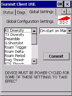
2.5.3 Global Settings Tab
Figure 2.9 SCU Global Settings Tab
The Global Settings tab allows you to define radio and security settings that apply to
all configs (profiles), along with settings that apply specifically to the SCU.

WORKABOUT PRO G2 Hand-Held With Windows Embedded CE 5.0 User Manual 27
Chapter 2: Basic Checkout
Global Settings Tab
The Global Settings in the table below can be edited in the SCU:
Global Setting Description Value Default
CCX features
Activates three CCX fea-
tures: AP-assisted roaming,
AP-specified maximum
transmit power & radio man-
agement.
On, Off Off
Certs Path Directory where certificates
for EAP authentication are
stored.
Valid directory
path up to 64 char-
acters.
Depen-
dent on
device.
Frag Thresh Packet is fragmented when
packet size (in bytes) exceeds
threshold.
Integer from 256
to 2346. 2346
G Shortslot 802.11g short slot timing
mode. Auto, Off, On Auto
Admin Pass-
word
Password that must be speci-
fied when Admin Login
button is pressed.
A string of up to
64 characters. SUMMIT
Hide Passwords
On - SCU as well as EAP
authentication dialog boxes
hide passwords, WEP keys
and other sensitive informa-
tion.
On, Off Off
LED Available only with
MCF10G. On, Off Off
Preamble Type of radio preamble or
headers. Auto, Short, Long Auto
Ping Payload Amount of data to be trans-
mitted on a ping. Bytes: 32, 64, 128,
256, 512 & 1024 32
Ping Timeout
ms
Amount of time in millisec-
onds that passes without a
response before ping request
is considered a failure.
Integer from 0 to
30000. 5000

Chapter 2: Basic Checkout
Global Settings Tab
28 WORKABOUT PRO G2 Hand-Held With Windows Embedded CE 5.0 User Manual
Ping Delay ms Amount of time in millisec-
onds between successive ping
requests.
Integer from 0 to
7200000. 1000
Roam Delta
Amount by which second
AP’s RSSI must exceed the
moving average RSSI for the
current AP before the radio
will attempt to roam to a
second AP.
dBm: 5, 10, 15,
20, 25, 30, 35 15
Roam Period
Following an association or
roam scan (with no roam),
the number of seconds the
radio
collects RSSI scan data
before considering roaming.
Seconds: 5, 10, 15,
20, 25, 30, 35, 40,
45, 50, 55, 60 10
Roam Trigger
If RSSI from AP is less than
roam trigger value, radio per-
forms roam scan or probes
for an AP with stronger
signal.
dBm: -50, -55, -
60,
-65, -70, -75 -70
RTS Thresh Packet size above which
RTS/CTS is required on link. An integer from 0
to 2347. 2347
RX Diversity Defines how to handle
antenna diversity when
receiving data from AP.
-On-Start on
Main: On startup,
use main antenna.
-On-Start on Aux:
On startup, use
auxiliary antenna.
-Main only: Use
main antenna only.
-Aux only: Use
auxiliary antenna
only.
On-Start
on Main
Global Setting Description Value Default
WORKABOUT PRO G2 Hand-Held With Windows Embedded CE 5.0 User Manual 29
Chapter 2: Basic Checkout
Status Tab
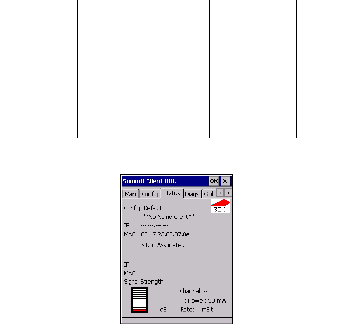
2.5.4 Status Tab
Figure 2.10 SCU Status Tab
The Status tab provides status information including IP address and MAC address
for the client radio, IP address and MAC address for the AP, signal strength,
channel, transmit power and data rate.
TX Diversity Defines how to handle
antenna diversity when trans-
mitting data to AP.
-Main only: Use
main antenna only.
-Aux only: Use
auxiliary antenna
only.
-On: Use diversity.
On
WMM Use Wi-Fi Multimedia
Extensions, also know as
WMM. On, Off Off
Global Setting Description Value Default
Chapter 2: Basic Checkout
Diags Tab
30 WORKABOUT PRO G2 Hand-Held With Windows Embedded CE 5.0 User Manual
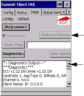
2.5.5 Diags Tab
Figure 2.11 Diags Tab
Use the Diags tab as a troubleshooting tool. The functions are as follows:
•(Re)Connect: Enables/Disables the radio, applies/reapplies current config
and tries to associate and authenticate to the wireless LAN, logging all
activity in the output area at bottom of the dialog box.
•Release/Renew: Obtains a new IP address through DHCP and logs all
activity in the output area.
•Start Ping: Starts a continuous ping to the address in the text box next to
this button. This is a toggle button so when you tap on it, it changes to Stop
Ping. Closing this window or tapping on another button also stops the ping.
•Diagnostics: Attempts to connect or reconnect to an AP, and provides a
more detailed dump of data than if you used (Re)connect. The dump
includes the radio state, config settings, global settings and BSSID list
of APs. The SCU is saved to a file called _sdc_diag.txt in the Windows
directory.
Ping Address
Ping Results

WORKABOUT PRO G2 Hand-Held With Windows Embedded CE 5.0 User Manual 31
Chapter 2: Basic Checkout
Checking The Scanner
2.6 Checking The Scanner
If your WORKABOUT PRO G2 is equipped with an internal scanner, you can test it
to ensure that it is operating properly. Point the scanner window at a bar code that
your scanner was designed to decode—for example, a 1D UPC bar code or 2D bar
code. Press the SCAN button or pistol trigger, and check for a valid decode on the
hand-held’s screen.
Performance is improved if you disable all unneeded bar codes in the Bar Codes
screen. Review “Scanner Settings” on page 135 for details about bar codes.
2.7 Using Microsoft® ActiveSync®
ActiveSync®—Microsoft PC connectivity software—can be used to connect the
hand-held to PCs running this software.
Note: Keep in mind that you’ll need to run the USB Setup program to configure
your workstation before connecting the WORKABOUT PRO G2 via USB.
By connecting the WORKABOUT PRO G2 to a PC with a cable and running
ActiveSync on the PC, you can:
• View WORKABOUT PRO G2 files from Windows Explorer.
• Drag and drop files between the WORKABOUT PRO G2 and the PC in the
same way that you would between PC drives.
• Back up WORKABOUT PRO G2 files to the PC, then restore them from
the PC to the hand-held again, if needed, and so on.
To install ActiveSync, follow the step-by-step instructions provided with the
program’s setup wizard. Refer to the following website for details:
http://www.microsoft.com/windowsmobile/addons/default.mspx
2.8 Resetting The Hand-Held
2.8.1 Performing A Warm Reset
To execute a warm reset:
• Press and hold down the [BLUE] key and the [ENTER/ON] key simulta-
neously for a minimum of six seconds.
A warm reset closes open applications; any unsaved data are lost. Installed
programs and saved data are preserved.

Chapter 2: Basic Checkout
Performing A Cold Reset – Accessing The BooSt Menu
32 WORKABOUT PRO G2 Hand-Held With Windows Embedded CE 5.0 User Manual
Note: You do not need to reset your WORKABOUT PRO G2 after configuring
the radio.
2.8.2 Performing A Cold Reset – Accessing The BooSt Menu
• Press and hold down the centre [SCAN] key and then press the [BLUE] and
[ENTER] keys simultaneously for a minimum of six seconds.
After a cold reset, the BooSt menu appears, listing possible BooSt commands.
• To load the Windows Embedded CE 5.0 operating system, type 1.
Note: Authorized personnel can perform a ‘clean start’. A clean start resets
not only the registry settings to factory defaults, but also erases any
files or applications stored or installed on the built-in flash file sys-
tem. After a clean start, anything that is not part of the OS image is
erased. Only data stored on a SD/MMC card or externally to the
device on a USB memory stick or on a PC is preserved during a
clean start.

WORKABOUT PRO G2 Hand-Held With Windows Embedded CE 5.0 User Manual 33
GETTING TO KNOW YOUR WORKABOUT PRO G2 3
3.1 Features Of The WORKABOUT PRO G2 ..................35
3.2 The Battery...................................36
3.2.1 Battery Safety.............................36
3.2.2.1 Battery Swap Time .....................37
3.2.2 Removing The Battery Pack.....................37
3.2.3 Charging The Battery.........................37
3.2.3.1 Chargers And Docking Stations . . . . . . . . . . . . . . . 38
3.3 Switching The Hand-Held On And Off....................38
3.4 The Keyboard..................................39
3.4.1 Modifier Keys ............................39
3.4.1.1 Activating Modifier Keys . . . . . . . . . . . . . . . . . . 40
3.4.1.2 Locking Modifier Keys...................40
3.4.2 The Keys...............................40
3.4.3 Function Keys And Macro Keys . . . . . . . . . . . . . . . . . . . 41
3.4.3.1 Function Keys........................42
3.4.3.2 Macro Keys (WORKABOUT PRO C G2 Only) . . . . . . 42
3.4.4 52-Key Keyboard – Accessing Alpha Keys . . . . . . . . . . . . . 42
3.4.5 25-Key Keyboard – Accessing Alphanumeric Keys . . . . . . . . . 42
3.4.6 The Keypad Backlight........................44
3.5 The Display...................................44
3.5.1 Adjusting The Display Backlight...................44
3.5.2 Calibrating The Touchscreen.....................45
3.6 WORKABOUT PRO G2 Indicators......................46
3.6.1 LED..................................46
3.6.2 Audio Indicators...........................46
3.6.2.1 Adjusting WORKABOUT PRO G2 Speaker Volume. . . . 47
3.6.3 Onscreen Indicators..........................47
3.7 Monitoring The Battery And Maximizing Run Time.............49
3.7.1 Storing Batteries...........................50
3.8 Uploading Data In A Docking Station.....................51
3.9 Bluetooth Radio................................51
3.10 The SD/MMC Card—Adding Memory ...................51
3.10.1 Inserting The Card..........................51
34 WORKABOUT PRO G2 Hand-Held With Windows Embedded CE 5.0 User Manual
3.11 General Maintenance ............................52
3.11.1 Caring For The Touchscreen.....................52
3.11.2 Cleaning The WORKABOUT PRO G2...............52
WORKABOUT PRO G2 Hand-Held With Windows Embedded CE 5.0 User Manual 35
Chapter 3: Getting To Know Your WORKABOUT PRO G2
Features Of The WORKABOUT PRO G2
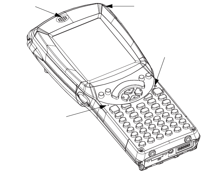
3.1 Features Of The WORKABOUT PRO G2
Figure 3.1 Front Of WORKABOUT PRO G2
Speaker Stylus
Microphone Port
LED
(Light Emitting Diode)
Chapter 3: Getting To Know Your WORKABOUT PRO G2
The Battery
36 WORKABOUT PRO G2 Hand-Held With Windows Embedded CE 5.0 User Manual
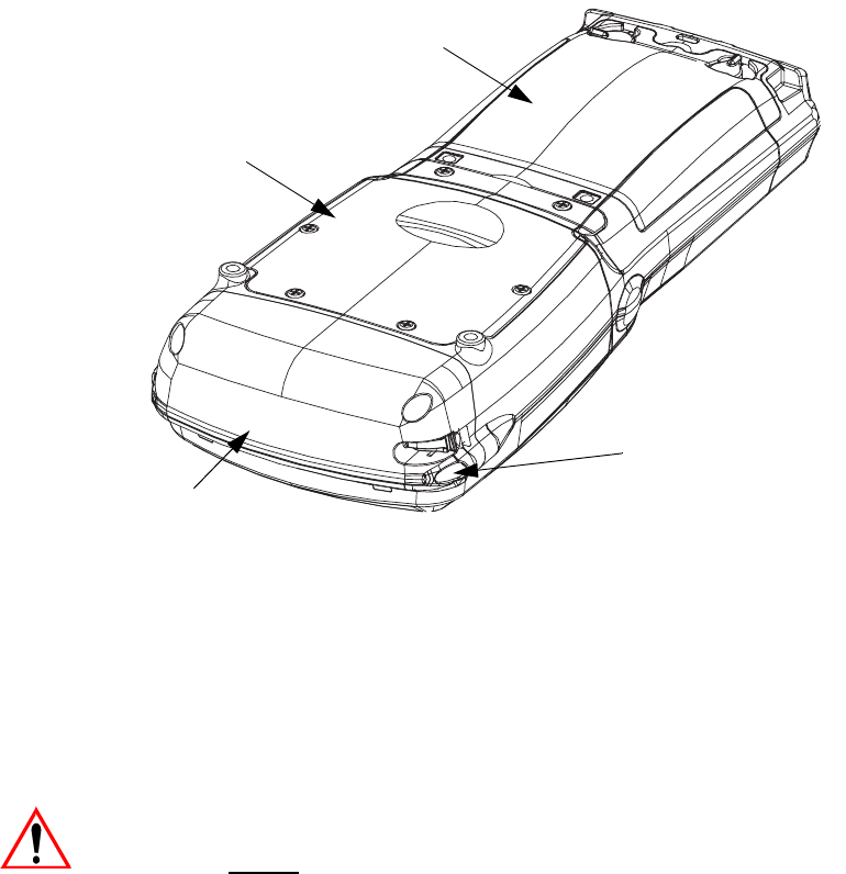
Figure 3.2 Back Of WORKABOUT PRO G2
3.2 The Battery
The hand-held operates with a Lithium-Ion battery pack. Preparing the unit for
operation requires that a battery pack be charged and installed in the
WORKABOUT PRO G2.
3.2.1 Battery Safety
Important: Before attempting to install, use or charge the battery pack, it is
critical that you review and follow the important safety guidelines
in the guide entitled ‘WORKABOUT PRO Hand-Held Computer
Regulatory & Warranty Guide’, PN 8000126.
Stylus
(Pointing Tool)
Scanner Window
Battery Pack
Tether Port
Warning Label
Battery Cover
Back Cover
End Cap
Stylus
(pointing tool)

WORKABOUT PRO G2 Hand-Held With Windows Embedded CE 5.0 User Manual 37
Chapter 3: Getting To Know Your WORKABOUT PRO G2
Removing The Battery Pack
3.2.2 Removing The Battery Pack
Important: Always switch the unit off before changing the battery. If you do
not turn the hand-held off before removing the battery, it may be
necessary to reboot the unit. Any active sessions may be lost.
While the battery is being replaced, the WORKABOUT PRO G2
backup battery will save the current data for up to 5 minutes.
Refer to “Installing The Battery And Switching The Unit On” on page 12.
3.2.2.1 Battery Swap Time
Assuming the default power saving parameters and battery reserve level have not
been altered, battery swap time is approximately 5 minutes—you will not lose data
if the battery is replaced within this time frame.
To protect data, the safest place to store data is on a SD/MMC memory card or
externally to the device on a USB memory stick or on a PC.
To protect against data loss, the unit will automatically shut down with enough
reserve in the main battery to last up to 99 hours, the default setting. (Refer to
“Suspend Threshold” on page 102 for details about reserving battery power for data
backup purposes.) Even when the hand-held shuts down, the backup battery
continues to draw a trickle charge from the main battery to maintain the data stored
in the unit until a new battery can be installed.
3.2.3 Charging The Battery
Batteries shipped from the factory are charged to approximately 40% of capacity.
They must be fully charged prior to use.
Keep in mind also that, along with the main battery, the WORKABOUT PRO is
equipped with an internal, backup battery that preserves data stored on the unit
while the main battery is swapped.
Important: The backup battery is trickle charged from the main battery. To
maximize battery life, avoid excessive discharging and recharging
of the backup battery by keeping the main battery fully charged.
IF YOU ARE POWERING UP A NEW UNIT, a warning message
may appear on the screen indicating that the backup battery
capacity is low. To recharge the backup battery, you must fully
charge the WORKABOUT PRO with the main battery installed in
the unit. An overnight charge is recommended.

Chapter 3: Getting To Know Your WORKABOUT PRO G2
Chargers And Docking Stations
38 WORKABOUT PRO G2 Hand-Held With Windows Embedded CE 5.0 User Manual
3.2.3.1 Chargers And Docking Stations
Important: FOR DETAILED INFORMATION about chargers and docking
stations, refer to “Peripheral Devices & Accessories” on
page 213.
Lithium Ion battery packs must be charged before use. These batteries can be
charged with a variety of chargers and docking stations. These include:
• Desktop Docking Station (Model # WA4003-G2)—operates as both a
charger and a docking station. Operating as a charger, both the battery
installed in the hand-held and a spare battery can be charged simulta-
neously.
• Quad Docking Station (Model # WA4004-G1)—can charge the battery of
up to four WORKABOUT PROs inserted in the docking station.
• Single Battery Charger (Model # WA3001-G1)—charges a single battery.
• Quad Battery Charger (Model # WA3004-G1)—charges up to four spare
Standard or High-Capacity WORKABOUT PRO battery packs.
It can take up to 5 hours to charge a battery. The WORKABOUT PRO intelligent
charging system protects the battery from over-charging by terminating the charge
process when the battery is at maximum capacity.
Note: Refer to “Monitoring The Battery And Maximizing Run Time” on page 49
for additional information about the battery.
Important: To avoid damaging the battery, chargers will not begin the charge
process until the battery temperature is between 0° C to 45 °C
(32° F to 113° F).
3.3 Switching The Hand-Held On And Off
Switching On The WORKABOUT PRO G2
Note: Whenever the battery cover is removed, an auto-shutoff switch is acti-
vated. The battery cover must be installed before the unit can be switched
on.
• Press and hold down the [ENTER/ON] key for at least one second.
• When the LED flashes green, release the [ENTER/ON] button.

WORKABOUT PRO G2 Hand-Held With Windows Embedded CE 5.0 User Manual 39
Chapter 3: Getting To Know Your WORKABOUT PRO G2
The Keyboard
If the unit does not power up, the power ON/OFF switch located in the battery
compartment may be set to OFF. In this case, you’ll need to remove the battery
cover and battery and slide the ON/OFF switch to ON.
The startup screen is displayed.
Note: If the WORKABOUT PRO G2 is in suspend state, pressing [ENTER/ON]
key ‘wakes’ the unit from this state. The screen in which you were working
before the computer entered suspend state is displayed.
Switching Off The WORKABOUT PRO G2 (Suspend)
Important: Keep in mind that turning off the WORKABOUT PRO does not
result in a complete reboot; rather, the unit enters a power-saving,
“suspend” state. When the unit is turned on from suspend state,
operation resumes within a few seconds.
To switch off the WORKABOUT PRO G2:
• Press the [BLUE] key, and then press the [ENTER/ON] key.
3.4 The Keyboard
The WORKABOUT PRO G2 is available in two models, each with it’s own
keyboard layout. The WORKABOUT PRO C G2 model is equipped with a 52-key,
alphanumeric keyboard; the WORKABOUT PRO S G2 model is equipped with a
25-key numeric keyboard.
Most of the keys on these keyboards operate much like a desktop computer. Where a
key or key function is not consistent with the PC keyboard, the differences are
noted.
The [FN/BLUE] and [FN/ORANGE] modifier keys provide access to additional
keys and system functions. These functions are colour coded in orange and blue
print above the keyboard keys.
3.4.1 Modifier Keys
The [SHIFT], [CTRL], [ALT], [FN/BLUE] and [FN/ORANGE] keys are modifier
keys. Pressing a modifier key changes the function of the next key pressed. For
example, on a WORKABOUT PRO C G2, 52-key keyboard, a square bracket is
printed in orange print above the [4] key. Pressing the [FN/ORANGE] key followed
by the [4] key displays a square bracket rather than the number 4.
Chapter 3: Getting To Know Your WORKABOUT PRO G2
Activating Modifier Keys
40 WORKABOUT PRO G2 Hand-Held With Windows Embedded CE 5.0 User Manual
The [SHIFT], [CTRL] and [ALT] keys operate much like a desktop keyboard except
that they are not chorded (two keys held down simultaneously). The modifier key
must be pressed first followed by the key whose function you want modified.
3.4.1.1 Activating Modifier Keys
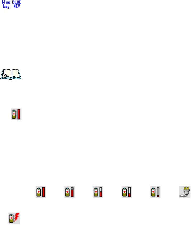
When a modifier key is pressed once, it is displayed in lowercase letters in the
taskbar at the bottom of the hand-held screen. For example, if the [CTRL] key is
pressed, ctrl key is displayed at the bottom of the unit screen. Once the next key is
pressed, the modifier key becomes inactive and disappears from the taskbar.
Keep in mind, however, that the ‘One Shot’ function allows you to determine how
many key presses will lock a modifier key ‘on’ – one press or two. Refer to
“Keyboard One Shot Modes” on page 92 for details.
3.4.1.2 Locking Modifier Keys
When a modifier key is pressed twice, it is ‘locked’ on. A ‘locked’ modifier key is
displayed in uppercase letters in the taskbar. For example, pressing the [CTRL] key
twice locks it on—it is displayed as CTRL KEY in the taskbar at the bottom of the
computer screen.
The locked modifier key will remain active until it is pressed a third time to unlock
or turn it off. Once a modifier key is unlocked, the uppercase representation at the
bottom of the screen is no longer displayed.
3.4.2 The Keys
The [SHIFT] Key
The [SHIFT] key is used to display uppercase alpha characters and provide access to
the symbols above the numeric keys.
The Arrow Keys
The Arrow keys move the cursor around the screen in the direction of the arrow: up,
down, left and right. The cursor is the flashing box or underline character that
indicates where the next character you type will appear.
WORKABOUT PRO G2 Hand-Held With Windows Embedded CE 5.0 User Manual 41
Chapter 3: Getting To Know Your WORKABOUT PRO G2
Function Keys And Macro Keys
The [SPACE] Key
Pressing this key inserts a blank space between characters. In a Windows dialog
box, pressing the [SPACE] key enables or disables a checkbox. On WORKABOUT
PRO S G2 models, this key is accessed by key combination – [FN/ORANGE] [0]
(zero).
The [BKSP/DEL] Key
The [BKSP] key (sometimes referred to as destructive backspace) moves the cursor
one character to the left, erasing the incorrectly entered key stroke.
The [DEL] key ([FN/BLUE] [BKSP]) erases the character at the cursor position.
The [CTRL] And [ALT] Key
The [CTRL] and [ALT] keys modify the function of the next key pressed and are
application dependent.
The [TAB] Key
Typically, the [TAB] key moves the cursor to the next field to the right or
downward.
The [ESC] Key
Generally, this key is used as a keyboard shortcut to close the current menu, dialog
box or activity and return to the previous one.
The [SCAN] Keys
All units are equipped with three yellow [SCAN] keys – one on the left side and one
on the right side of the unit along with a curved, yellow scan bar just below the
WORKABOUT PRO G2 display. For units that do not have internal scanners, this
key can be re-mapped to another function.
3.4.3 Function Keys And Macro Keys
In addition to the standard keyboard functions, the WORKABOUT PRO G2
supports Function keys and Macro keys. All Function and Macro keys can be
custom defined for each application.

Chapter 3: Getting To Know Your WORKABOUT PRO G2
Function Keys
42 WORKABOUT PRO G2 Hand-Held With Windows Embedded CE 5.0 User Manual
3.4.3.1 Function Keys
The WORKABOUT PRO G2 keyboard is equipped with a total of 14 function keys.
Function keys [F1] to [F4] are located across the top of the keyboard next to the
[TAB], [ALT], [CTRL] and [ESC] keys and are directly accessible – a key
combination is not required. Ten additional function keys are colour coded in blue
print on the unit body; these keys are accessed by executing a key combination,
[FN/BLUE] followed by the appropriate numeric key.
For example, to access function key [F7]:
• Press the [FN/BLUE] key followed by the [7] key – the numeric key to
which function key [F7] is mapped.
• To access function key [F8], press [FN/BLUE] [8], and so on.
3.4.3.2 Macro Keys (WORKABOUT PRO C G2 Only)
Important: Refer to “Keyboard Macro Keys” on page 93 for details about
creating macros.
WORKABOUT PRO G2 hand-helds are equipped with a series of macro keys that
can be programmed to replace frequently used keystrokes, along with the function
of executable keys like the [ENTER] key, the [BKSP] key, any function key and
arrow key, and so on.
Alphanumeric (52-keys) keyboards have three macro keys: [M1] to [M3]. These
keys are colour coded in orange print above alpha keys [O], [P] and [Q].
To access a macro key:
• Press the [FN/ORANGE] key followed by the appropriate alpha key from
[O] to [Q].
To access macro key [M1], press [FN/ORANGE] [O].
To access macro key [M2], press [FN/ORANGE] [P], and so on.
3.4.4 52-Key Keyboard – Accessing Alpha Keys
The alpha and numeric keys on WORKABOUT PRO C G2 units are directly
accessible from the keyboard – no key combination is required.
3.4.5 25-Key Keyboard – Accessing Alphanumeric Keys
On 25-key WORKABOUT PRO G2s, while numeric keys are directly accessible,
all alpha characters are printed on the unit plastic in orange typeface above the
numeric keys. An indicator in the left corner of the taskbar displays the currently

WORKABOUT PRO G2 Hand-Held With Windows Embedded CE 5.0 User Manual 43
Chapter 3: Getting To Know Your WORKABOUT PRO G2
25-Key Keyboard – Accessing Alphanumeric Keys
selected character. To access an alpha character, first press the [ORANGE] key and
then press the numeric key above which the alpha character you want to type is
printed.
Choosing A Single Alpha Character
The examples below illustrate how to access, A, B and C, all of which are printed in
orange characters above the numeric key [2].
Important: The letters you choose appear in the taskbar, providing a visual
indicator of which letter will be displayed on the screen.
To choose the letter a:
• Press the [FN/ORANGE] key, and press the numeric key [2].
Note: To choose the second, third or fourth alpha character assigned to a
numeric key, you may want to lock the [FN/ORANGE] key ‘on’. By
default, the [FN/ORANGE] key is locked ‘on’ when pressed once. How-
ever, depending on how your unit is set up in the ‘One Shots’ tab, you may
find that you need to press the [ALPHA/ORANGE] key twice to lock it
‘on’. Refer to “Keyboard One Shot Modes” on page 92for details.
To choose the second letter in the sequence—in this example, the letter b:
• Lock the [FN/ORANGE] key ‘on’. ‘ORG KEY is displayed in upper-case
characters in the taskbar to indicate that this key is locked ‘on’.
• Press numeric key [2] twice to display the letter b.
To choose the third letter in the sequence—in this example, the letter c:
• Lock the [ALPHA/ORANGE] key ‘on’.
• Press numeric key [2] three times to display the letter c.
Note: Keep in mind that there is a timeout if you pause for one second between
key presses when selecting the second, third or fourth letters on a key. For
example, suppose you want to type the letter ‘c’–you’d need to press the
[2] key three times. With the [FN/ORANGE] key locked ‘on’, if you press
[2] twice and then pause between key presses for 1 second, the letter ‘b’
will be selected automatically.
Creating Uppercase Letters
To display a capital letter:

Chapter 3: Getting To Know Your WORKABOUT PRO G2
The Keypad Backlight
44 WORKABOUT PRO G2 Hand-Held With Windows Embedded CE 5.0 User Manual
• Press the [FN/ORANGE] key and then the [SHIFT] key before typing the
alpha character.
Note: If you want to use uppercase characters at all times, press [FN/BLUE]
[SHIFT]. An icon of an uppercase ‘A’ is displayed in the taskbar indicating
that all letters will be displayed as uppercase characters.
Choosing Multiple Alpha Characters
• Lock the [FN/ORANGE] key ‘on’.
Each time you press a numeric key from [2] through [9], an alpha character will be
displayed on the screen. Remember that you can refer to the softkey bar for a visual
indication of which alpha key will be displayed on the screen.
•Once you have finished typing alpha characters, remember to turn off
or unlock the [FN/ORANGE] key.
3.4.6 The Keypad Backlight
The intensity of the keypad backlight and the conditions under which this backlight
is activated can be configured using the Keyboard icon in the Windows Embedded
CE 5.0 Control Panel. The behaviour of the keypad backlight is tailored in the
Keyboard Properties dialog box. Refer to “Keyboard Backlight” on page 91 for
details about this option.
Note: Keep in mind that this option may be restricted to supervisory use only.
3.5 The Display
WORKABOUT PRO G2s are equipped with display backlighting to improve
character visibility in low light conditions. The backlight switches on when a key is
pressed and the ambient light is below the set threshold.
3.5.1 Adjusting The Display Backlight
The Display Properties dialog box in the Control Panel allows you to determine
the behaviour of the display backlight and its intensity
Note: Refer to “Display Backlight” on page 87 for details about the Display
Properties dialog box.
WORKABOUT PRO G2 Hand-Held With Windows Embedded CE 5.0 User Manual 45
Chapter 3: Getting To Know Your WORKABOUT PRO G2
Calibrating The Touchscreen
3.5.2 Calibrating The Touchscreen
If your WORKABOUT PRO G2 touchscreen has never been calibrated, or if you
find that the stylus pointer is not accurate when you tap on an item, use the Stylus
Properties dialog box in the Control Panel to recalibrate the screen.
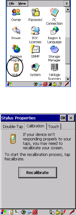
•In the Control Panel, choose the Stylus icon to display the Stylus Proper-
ties window.
Figure 3.3 Stylus Icon
• Select the Calibration tab, and then choose the Recalibrate button.
Figure 3.4 Calibration Screen
• Follow the directions on the calibration screen to calibrate the screen.
Chapter 3: Getting To Know Your WORKABOUT PRO G2
WORKABOUT PRO G2 Indicators
46 WORKABOUT PRO G2 Hand-Held With Windows Embedded CE 5.0 User Manual
3.6 WORKABOUT PRO G2 Indicators
The WORKABOUT PRO G2 uses an LED (Light Emitting Diode), onscreen
messages and audio tones to indicate the various conditions of the hand-held, the
batteries, the scans and so on.
3.6.1 LED
A single, two-coloured LED is located on the upper-right side of the keyboard, just
above the [ON] key. When you press [ON], the LED flashes green to indicate that
the unit has been powered up. The LED table following outlines the behaviour of
the LED while the unit is docked in a charger.
Keep in mind that the application running on the WORKABOUT PRO G2 can
dictate how the LED operates. Review the documentation provided with your
application to determine LED behaviour.
If the unit is attached to an external power supply, the hand-held LED reflects the
battery charge status.
3.6.2 Audio Indicators
The audio speaker provides a variety of sounds when a key is pressed, a keyboard
character is rejected, scan input is accepted or rejected, an operator’s entry does not
match in a match field or the battery is low. To specify how you want your
WORKABOUT PRO G2 to respond under various conditions, refer to “Volume
And Sound Properties” on page 99.
The volume keys are located above [UP ARROW] and [DOWN ARROW]. The
increase volume key is labelled with a plus symbol and the decrease volume
key is labelled with a minus symbol .
LED Behaviour Charge Status
Solid Green Charge complete.
Fast Blinking Green Charge in progress. Battery charged to less than 80%
capacity.
Slow Blinking Green Battery charged to greater than 80% of capacity.
Solid Red Temperature outside charge range (0° C to 50° C).
Blinking Red Battery is not charging. Battery fault.
WORKABOUT PRO G2 Hand-Held With Windows Embedded CE 5.0 User Manual 47
Chapter 3: Getting To Know Your WORKABOUT PRO G2
Adjusting WORKABOUT PRO G2 Speaker Volume
3.6.2.1 Adjusting WORKABOUT PRO G2 Speaker Volume
• Lock the [FN/BLUE] key ‘on’ and then, press [UP ARROW]—the
increase volume key or [DOWN ARROW]—the decrease volume key until
the volume meets your requirements.
• Remember to press the [FN/BLUE] key again to turn it ‘off’.
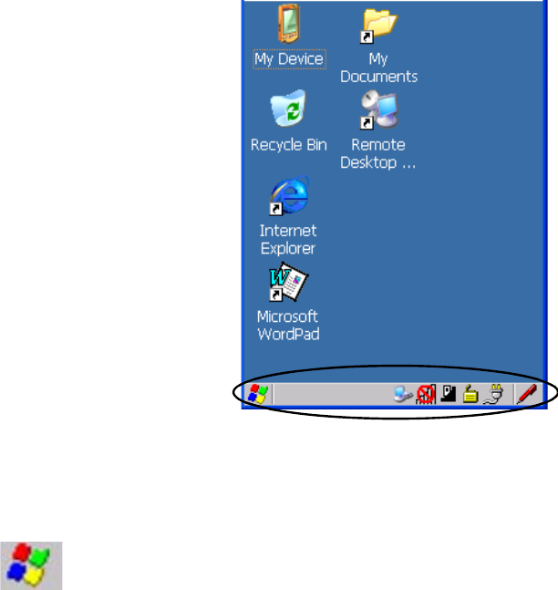
3.6.3 Onscreen Indicators
The taskbar at the bottom of the screen displays a variety of system status indicators.
Figure 3.5 Taskbar
The taskbar changes dynamically, and only those icons that are applicable are
displayed. For example, if a radio is not installed in your WORKABOUT PRO G2,
the radio signal icon is not displayed in the taskbar.
Windows® Start Button
If you are using the touchscreen, you can either tap the Windows icon at the bottom
left of the screen, or press [FN/BLUE] [.] (period) to display the Start Menu, and
then tap on the desired application.
Chapter 3: Getting To Know Your WORKABOUT PRO G2
Onscreen Indicators
48 WORKABOUT PRO G2 Hand-Held With Windows Embedded CE 5.0 User Manual
Modifier Key Indicators
[SHIFT], [CTRL], [ALT], [FN/BLUE] and [FN/ORANGE] are modifier keys that
when pressed, are displayed in the taskbar to indicate that they are active. If a
modifier key is locked ‘on’, it is displayed in uppercase characters. For example, if
the [FN/BLUE] key is locked on, it is displayed as BLUE KEY in the taskbar. A locked
modifier key remains active until it is pressed again to unlock or turn it off.
If a modifier key has been pressed but is not locked on, it is displayed in the taskbar
in lowercase characters – for example, blue key. It will remain active only until the next
key is pressed at which point, the modifier key is turned off.
Note: The locking function of the modifier keys can be set up so that pressing
one of these keys once will lock the key ‘on’. They can also be set up so
that they must be pressed twice to be locked ‘on’. Refer to “Keyboard One
Shot Modes” on page 92for details.
Battery Gauge
The battery shaped icon displayed in the taskbar provides a visual indication of the
remaining battery power. The icon acts as a meter that is either full, at three-quarter
level, half, quarter level or empty.
When the battery level is low—approximately 15 minutes from empty—a warning
window pops up. When the battery power is completely depleted, a final warning
window indicates that the WORKABOUT PRO G2 will be powered down.
If the WORKABOUT PRO G2 is using external AC power, an AC icon is displayed
in the taskbar.
Battery Charge
The battery charge icon is displayed in the taskbar when the hand-held battery is
being charged.
AC ConnectionFull
75%
50% 25% Empty
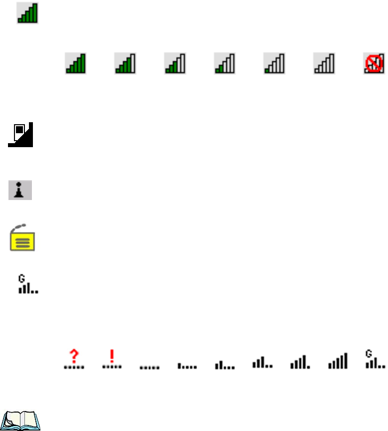
WORKABOUT PRO G2 Hand-Held With Windows Embedded CE 5.0 User Manual 49
Chapter 3: Getting To Know Your WORKABOUT PRO G2
Monitoring The Battery And Maximizing Run Time
802.11 Radio Signal Quality
Increasing radio signal quality is represented by longer, filled bars within this icon.
Docking Device
When a hand-held is inserted in a docking station or charger, an associated icon
appears in the taskbar.
Bluetooth Radio
This icon displayed in the taskbar represents the installed Bluetooth radio.
Security Level
Security levels can be set to limit user access. In addition, applications can be
restricted to prevent inadvertent changes.
Wireless WAN
These icons provide access to and information about the WORKABOUT PRO G2
GSM/GPRS wide area networking status. Refer to Appendix B: “Wireless WAN”
for details about each of these taskbar icons.
3.7 Monitoring The Battery And Maximizing Run Time
Note: When the main battery is at 50% capacity, a ‘low battery’ warning is dis-
played. When the battery is at approximately 10% capacity, a ‘very low
main battery’ notification appears.
Under normal operating conditions, fully charged Standard Batteries hold a charge
for up to 8 hours. High-Capacity batteries can hold a charge for up to 12 hours.
Good No Radio
Reception
Weak
Reception Link
Chapter 3: Getting To Know Your WORKABOUT PRO G2
Storing Batteries
50 WORKABOUT PRO G2 Hand-Held With Windows Embedded CE 5.0 User Manual
As Lithium Ion batteries age, their capacity decreases gradually, and they are
generally considered depleted after approximately 2 years of use (less than 60% of
original capacity remaining). Keep in mind however that heavy usage or operating
the unit at temperature extremes will shorten the battery life.
Lithium Ion batteries do not require conditioning cycles and the WORKABOUT
PRO battery system (including chargers) requires no user interaction to maintain
peak performance.
To maximize the run time of your batteries, consider the following:
• The display backlight is the largest drain on the battery. Try to keep its
brightness as low as possible.
• The hand-held is ‘event’ driven—that is, when the unit is not in use, it
reverts to sleep mode (even when it appears to be running), saving battery
power. Events include a key press, touchscreen taps and scan triggers.
Power consumption is reduced if you avoid unnecessary events, and allow
the unit to sleep as much as possible.
• The battery is a ‘smart battery’ with built-in intelligence.
Tapping on the Power icon in the Control Panel displays a dialog box that
provides detailed information about the battery status of the main and
backup batteries installed in your unit.
• When the hand-held is switched off, it goes into a low-power, suspend state
but continues to draw a small amount of power from the battery. This
should not be an issue unless the unit is left in suspend state for more than a
week—for long-term storage, the battery should be removed from the unit.
3.7.1 Storing Batteries
Long term battery storage is not recommended. If storage is necessary:
• Always try to use a ‘first-in first-out’ approach to minimize storage time.
• Lithium Ion batteries age much faster at elevated temperatures. Store batter-
ies at temperatures between 0° C and 20° C.
• Always charge batteries to at least 40 to 60% before storing them. Batteries
can be damaged by an over-discharge phenomenon that occurs when an
empty battery is stored for a long period of time such that the cell voltage
drops below a lower limit.
• To minimize storage degradation, recharge stored batteries to 40 to 60%
every 4 or 6 months to prevent over-discharge damage.

WORKABOUT PRO G2 Hand-Held With Windows Embedded CE 5.0 User Manual 51
Chapter 3: Getting To Know Your WORKABOUT PRO G2
Uploading Data In A Docking Station
• A ‘never used’ Li-Ion battery that has been stored for 3 years may have
limited or no useful life remaining once put into service. Think of batteries
as perishable goods.
3.8 Uploading Data In A Docking Station
Important: Review the documentation provided with the user application installed
in your WORKABOUT PRO before performing data uploads.
The desktop docking station and quad docking station allow the WORKABOUT
PRO G2 to link to an Ethernet network. They are typically used to upload
transaction data to a server computer when a radio link is not available.
Note: Refer to “Desktop Docking Station” on page 223 for more details.
The desktop docking station can complete batch uploads to a Client USB connected
PC or server. An optional 10/100baseT Ethernet module is also available.
Unlike the desktop docking station, the quad docking station supports only TCP/IP
connections to a PC or server through a 10/100baseT Ethernet connection.
When a WORKABOUT PRO is properly inserted in a docking station, a dock icon
is displayed in the navigation bar at the top of the screen. The unit also detects the
presence of the Ethernet network.
3.9 Bluetooth Radio
Note: Integrated Bluetooth class II radios are standard on WORKABOUT
PRO C and S G2 units. Keep in mind also that Bluetooth is available
simultaneously with WAN and 802.11g on a single unit.
The WORKABOUT PRO is equipped with an on-board Bluetooth radio. This type of
radio enables short range data communication between devices. The Bluetooth also
provides the capability to use a Bluetooth-enabled cellular phone as a data modem,
exchanging information with other Bluetooth devices and providing network access.
Refer to “Bluetooth Setup” on page 111for setup details.
3.10 The SD/MMC Card—Adding Memory
To add additional non-volatile memory to your hand-held, you can insert a Secure
Digital/Multi-Media Card (SD/MMC) through the battery compartment.
3.10.1 Inserting The Card
• Switch off the WORKABOUT PRO.

Chapter 3: Getting To Know Your WORKABOUT PRO G2
General Maintenance
52 WORKABOUT PRO G2 Hand-Held With Windows Embedded CE 5.0 User Manual
• Remove the battery cover and the battery.
A hinged door at the top of the battery compartment protects the connectors.
• Lift the hinged SD door by gently pulling upward on the metal tab.
• Orient the SD/MMC card according to the legend stamped into the battery
well plastic.
• Place the card in the slot with the card contacts down, and slide it inward
until it latches into place.
• Swing the hinged door back into place.
To remove the card:
• Gently press it inward slightly until the detent unlatches, and the card is
expelled from the slot.
3.11 General Maintenance
3.11.1 Caring For The Touchscreen
The top of the touchscreen is a thin, flexible polyester plastic sheet with a
conductive coating on the inside. The polyester can be permanently damaged by
harsh chemicals and is susceptible to abrasions and scratches. Using sharp objects
on the touchscreen can scratch or cut the plastic, or crack the internal conductive
coating.
The chemicals listed below must not come into contact with the touchscreen:
• sodium hydroxide,
• concentrated caustic solutions,
• benzyl alcohol, and
• concentrated acids.
If the touchscreen is used in harsh environments, consider applying a disposable
screen protector (WA6110). These covers reduce the clarity of the display slightly
but will dramatically extend the useful life of the touchscreen. When they become
scratched and abraded, they are easily removed and replaced.
3.11.2 Cleaning The WORKABOUT PRO G2
Important: Do not immerse the unit in water. Dampen a soft cloth with mild
detergent to wipe the unit clean.
•Use only mild detergent or soapy water to clean the hand-held unit.
WORKABOUT PRO G2 Hand-Held With Windows Embedded CE 5.0 User Manual 53
Chapter 3: Getting To Know Your WORKABOUT PRO G2
Cleaning The WORKABOUT PRO G2
• Avoid abrasive cleaners, solvents or strong chemicals for cleaning. The
plastic case is susceptible to harsh chemicals. The plastic is partially soluble
in oils, mineral spirits and gasoline. The plastic slowly decomposes in
strong alkaline solutions.
• To clean ink marks from the keypad and touchscreen, use isopropyl
alcohol.

WORKABOUT PRO G2 Hand-Held With Windows Embedded CE 5.0 User Manual 55
WORKING WITH WINDOWS EMBEDDED CE 5.0 4
4.1 Navigating In Windows Embedded CE 5.0..................57
4.1.1 Navigating Using A Touchscreen And Stylus . . . . . . . . . . . . 57
4.1.2 Navigating Using The Keyboard...................57
4.2 Working With Files, Folders And Programs..................58
4.3 The Startup Desktop..............................59
4.3.1 The Desktop Icons..........................60
4.3.2 The Taskbar..............................61
4.3.2.1 Using The Taskbar......................61
4.3.2.2 Customizing The Taskbar..................62
4.4 The Start Menu.................................63
4.4.1 The Desktop .............................64
4.4.2 Security Settings...........................64
4.4.3 Programs...............................66
4.4.4 Shortcuts...............................68
4.4.5 Settings................................69
4.4.6 Run..................................70
4.4.7 Shutdown...............................71
4.5 Using A Dialog Box..............................72

WORKABOUT PRO G2 Hand-Held With Windows Embedded CE 5.0 User Manual 57
Chapter 4: Working With Windows Embedded CE 5.0
Navigating In Windows Embedded CE 5.0
4.1 Navigating In Windows Embedded CE 5.0
Note: In order to access many of the menus discussed in this chapter, the secu-
rity level must be set to ‘Supervisor’ (see “Security Settings” on page 64).
Graphic user interfaces like Windows Embedded CE 5.0 for portable devices and
desktop Windows (2000, XP, etc.) utilize ‘point and click’ navigation. An
equivalent keyboard shortcut is also available for every ‘point and click’ action.
Windows Embedded CE 5.0 supports the same ‘point and click’ user interface and
keyboard shortcuts as desktop Windows with one difference—the ‘point and click’
action is accomplished using a touchscreen rather than a mouse. Actions can be
performed using any combination of keyboard shortcuts or touchscreen tapping.
4.1.1 Navigating Using A Touchscreen And Stylus
Note: If the touchscreen is not registering your screen taps accurately, the
touchscreen may need recalibration. Refer to “Calibrating The Touch-
screen” on page 45.
Each WORKABOUT PRO G2 is equipped with a stylus—a pointing tool that looks
like a pen—stored in a slot at the top of the unit. The stylus is used to select objects
on the touchscreen.
Note: To prevent damage to the touchscreen, use only the stylus (pen) supplied
with your WORKABOUT PRO G2.
To choose an icon, open a file, launch an applet or open a folder:
• Double-tap the stylus on the appropriate icon.
4.1.2 Navigating Using The Keyboard
If your WORKABOUT PRO G2 touchscreen has been disabled, you can use the
keyboard to choose icons, navigate dialog boxes, display the desktop, and so on. If
your unit has already been fully configured and your application is launched at
startup, you’ll have little need for keyboard navigation, but you can refer to
Table 4.1 on page 58 for a description of the navigation keys.
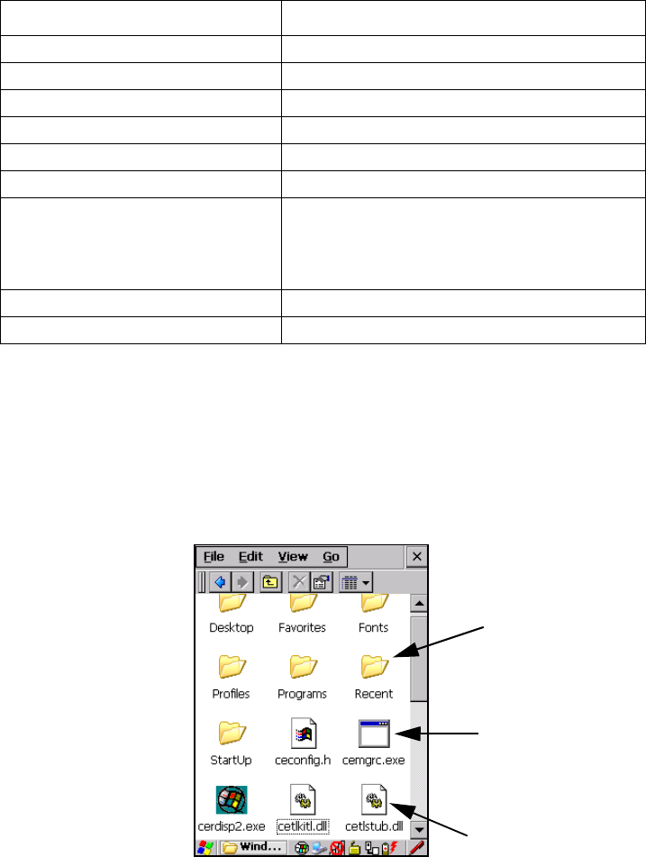
Chapter 4: Working With Windows Embedded CE 5.0
Working With Files, Folders And Programs
58 WORKABOUT PRO G2 Hand-Held With Windows Embedded CE 5.0 User Manual
Table 4.1 Keyboard Navigation
Keep in mind that unlike a desktop computer, the WORKABOUT PRO G2 does not
support key chording (pressing two keys at the same time). You must press one key
followed by the next in sequence. Refer to “Working With Files, Folders And
Programs” for additional details about keyboard navigation.
4.2 Working With Files, Folders And Programs
Figure 4.1 Working With Windows Icons
Operation Key or Key Combination
Switch between active applications [ALT] [TAB]
Open task manager [ALT] [ESC]
Move the cursor Arrow keys
Open file, folder or icon [ENTER]
Exit & Save [ENTER]
Close/Exit & Do Not Save [ESC]
Navigate Dialog Boxes
[TAB]
To move cursor up [SHIFT] [TAB]
To display the contents of the next ‘tab’ in
a dialog box [CTRL] [TAB]
Select Radio Button/Press Button [SPACE]
Go to Start Menu [BLUE][0]
Folder
File
Program Icon
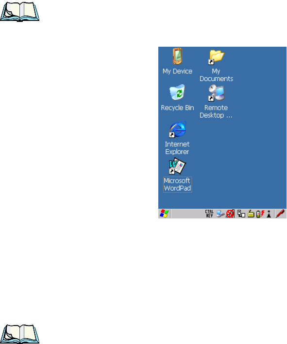
WORKABOUT PRO G2 Hand-Held With Windows Embedded CE 5.0 User Manual 59
Chapter 4: Working With Windows Embedded CE 5.0
The Startup Desktop
• Double-tap on the appropriate icon—either a folder icon, a program icon or
a file icon—to open or launch your selection.
If you’re using the keyboard:
• Use the arrow keys to highlight the icon you want to open or launch.
• Press [ENTER].
4.3 The Startup Desktop
When the WORKABOUT PRO G2 boots up, the startup desktop (shell) is
displayed. Any applications stored in the Startup folder start up immediately.
Note: The startup folder is located in \Windows\StartUp and
\Flash Disk\StartUp.
Figure 4.2 The WORKABOUT PRO G2 Startup Desktop
To access desktop icons:
• Double-tap on the icon to open a window or, in the case of an application
icon, launch an application.
On the keyboard:
• Use the arrow keys to highlight the icon, and press [ENTER] to launch the
highlighted icon.
Note: If the arrow keys do not highlight the desktop icons, the desktop may not
be selected. Press [FN/BLUE] [.] (period) to display the Start Menu, and
Chapter 4: Working With Windows Embedded CE 5.0
The Desktop Icons
60 WORKABOUT PRO G2 Hand-Held With Windows Embedded CE 5.0 User Manual
select Desktop. Now the desktop will be “in focus” and the arrow keys
will highlight the icons.
4.3.1 The Desktop Icons
The icons displayed in the startup desktop operate in much the same way as those
displayed on any standard PC desktop that is running Windows.
My Device
Choosing this icon displays the contents of your WORKABOUT PRO G2
computer. If you’re not sure how to work with the files, folders and programs
displayed, refer to “Working With Files, Folders And Programs” on page 58.
Recycle Bin
This option temporarily stores items that were deleted, allowing you to either
permanently delete or restore these items.
Internet Explorer
Choosing this icon launches Internet Explorer—a standard Windows Embedded CE
5.0 version. Keep in mind that your supervisor will need to set up access using the
Internet Options and the Network and Dial-up Connections icons in the Control
Panel.
Remote Desktop Connection
This option allows your WORKABOUT PRO G2 to communicate with a remote
desktop PC. “Remote Connect” on page 81 provides a website with step-by-step
instructions.
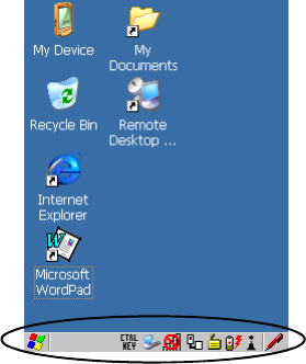
WORKABOUT PRO G2 Hand-Held With Windows Embedded CE 5.0 User Manual 61
Chapter 4: Working With Windows Embedded CE 5.0
The Taskbar
4.3.2 The Taskbar
Figure 4.3 The Taskbar
The WORKABOUT PRO G2 is equipped with a taskbar at the bottom of the screen.
It displays icons through which you can view the battery capacity and radio signal
quality of your unit. If the hand-held is attached to a charger, cradle, docking station
or PDM, an associated icon is displayed. In addition, the taskbar displays the
application(s) currently running on your unit and the security level assigned to your
WORKABOUT PRO G2.
The taskbar also displays active modifier keys: [SHIFT], [ALT], [CTRL],
[FN/BLUE] and [FN/ORANGE]. Keys that have been locked “on” are displayed in
uppercase letters. For example, if you have set the [CTRL] key Lock to “on” in the
Keyboard menu and you press the key, it is displayed as CTRL KEY in the taskbar. (For
detailed information on modifier keys and keyboard options, see “The Keyboard”
on page 39).
4.3.2.1 Using The Taskbar
A tooltip is displayed as each taskbar icon is highlighted. The tooltip provides the
status of each icon.
If you’re using the touchscreen:
• Tap and hold the stylus on an icon to display the icon's tooltip. Double-tap
the icon to open the Control Panel dialog box associated with the icon. For
example, double-tap the battery icon to display a dialog box listing the
current battery capacity information.
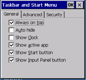
Chapter 4: Working With Windows Embedded CE 5.0
The Taskbar
62 WORKABOUT PRO G2 Hand-Held With Windows Embedded CE 5.0 User Manual
On the keyboard:
• Press [FN/BLUE] [.] (period) to display the Start Menu.
• Choose Shortcuts from the Start Menu, and then press the [RIGHT] arrow
key to display the sub-menu.
• Choose System Tray in the sub-menu.
• Use the arrow keys to highlight the icon in the taskbar about which you’d
like more information.
• Press [ENTER] to display the appropriate dialog box.
4.3.2.2 Customizing The Taskbar
To customize the taskbar so that it displays only those icons you require:
•In the Start Menu, choose Settings, and then Taskbar.
If you’re using the keyboard:
• Press [BLUE] [0] (zero) to display the Start Menu.
• Highlight the Settings option, highlight Taskbar in the sub-menu, and
press [ENTER].
The Taskbar and Start Menu dialog box is displayed.
Figure 4.4 Taskbar And Start Menu Settings
• Tap the stylus on the items you want to activate or deactivate. The check
mark indicates active items.
If you’re using the keyboard:
• Highlight the options you want to activate, and press the [SPACE] key to
select them. A check mark indicates active items.
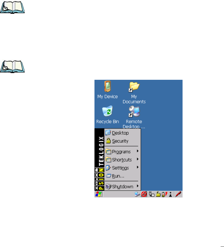
WORKABOUT PRO G2 Hand-Held With Windows Embedded CE 5.0 User Manual 63
Chapter 4: Working With Windows Embedded CE 5.0
The Start Menu
4.4 The Start Menu
Note: Some of the Start Menu items may be disabled based on the current
WORKABOUT PRO G2 security settings.
The Start Menu lists the operations you can access and work with. It is available
from the startup desktop or from within any application.
To display the menu:
• Press [FN/BLUE] [.] (period).
Note: Tap on the item in the menu with which you want to work.
Figure 4.5 Start Menu
If you’re using the keyboard:
• Use the arrow keys to highlight a menu item, and press [ENTER], or
If the menu item has an underlined character:
• Type the underlined alpha character. For example, to display the Security
dialog box, type the letter ‘s’.
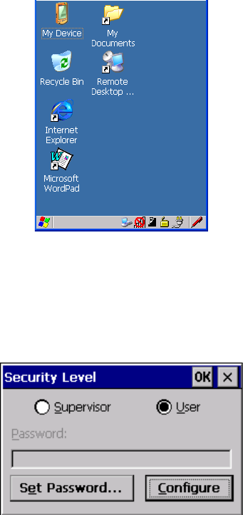
Chapter 4: Working With Windows Embedded CE 5.0
The Desktop
64 WORKABOUT PRO G2 Hand-Held With Windows Embedded CE 5.0 User Manual
4.4.1 The Desktop
Choosing the Desktop option from the Start Menu displays the WORKABOUT
PRO G2 desktop.
Figure 4.6 WORKABOUT PRO G2 Desktop
4.4.2 Security Settings
Choosing the Security option from the Start Menu displays a dialog box in which
you can define the access level for the WORKABOUT PRO G2: Supervisor or
User.
Figure 4.7 Security Levels

WORKABOUT PRO G2 Hand-Held With Windows Embedded CE 5.0 User Manual 65
Chapter 4: Working With Windows Embedded CE 5.0
Security Settings
Assigning The Supervisor Security Level
The security level is represented by an icon in the shape of a lock in the taskbar. The
security levels define the options accessible to the operator in the Start Menu and
the taskbar. By default, the security level is set to User, restricting access to only the
most basic Start Menu items.
To allow access to all the Start Menu and taskbar options:
•In the Security Level dialog box, tap on the radio button next to Supervisor.
•In the Password field, type the Supervisor level password. The default pass-
word is 123456.
• Tap on OK. You can now access all menu items in the Start Menu along
with the icons in the taskbar.
Changing A Password
Note: Keep in mind that this is the same password as that assigned through
the Password control panel applet. Refer to “Control Panel Icons” on
page 83.
To assign a password:
• Choose a security level, and enter the existing password in the Password
field.
• Tap on the Set Password button.
A dialog box labelled Password Properties is displayed.
• Type the new password in the Password: text box (all keyboard characters
are valid).
•In the Confirm Password: text box, retype the new password.
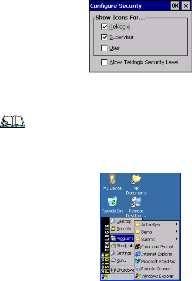
Chapter 4: Working With Windows Embedded CE 5.0
Programs
66 WORKABOUT PRO G2 Hand-Held With Windows Embedded CE 5.0 User Manual
Configuring Security
Choosing the Configure button displays the Configure Security dialog box.
Figure 4.8 Configuring Security
This dialog box allows you to determine which security levels will have an
associated icon displayed in the taskbar. By default, a security icon is not displayed
for user-level security.
Note: It is recommended that you enable ‘Allow Teklogix Security Level’ so that
authorized Psion Teklogix service personnel can access your unit should
it require maintenance.
4.4.3 Programs
• Choose Programs to display a sub-menu of options.
Figure 4.9 Program Sub-Menu
WORKABOUT PRO G2 Hand-Held With Windows Embedded CE 5.0 User Manual 67
Chapter 4: Working With Windows Embedded CE 5.0
Programs
ActiveSync®
This option allows you to connect to another device using ActiveSync.
Demo
This folder contains the Demo Imager, Demo Scanner, and Demo Signature
applications. Demo Imager is used for simple image-capturing purposes and for
displaying bar code data and bar code statistics on the same screen with image data
and information. Demo Scanner can be used to test how the hand-held reads and
writes RFID tags. Demo Signature allows you to capture a signature written on the
screen with your stylus and save it to a file.
Summit
This folder provides access to the Summit Client Utility (SCU), a utility that allows
you to configure your Summit 802.11g radio, model number RA2041.
Command Prompt
Command Prompt is used to access the DOS command prompt. At the prompt, you
can type DOS commands such as dir to display all the directories in the drive.
Internet Explorer
The WORKABOUT PRO G2 is equipped with Microsoft Internet Explorer for
Windows Embedded CE 5.0. You can access the Internet Options icon through the
Start Menu under Settings, Control Panel or by double-tapping on the desktop
Internet Explorer icon.
Remote Connect
Remote Connect is a WORKABOUT PRO G2 application used to connect to a
Windows Terminal Server so that you can run a “session” on the Server machine
using the WORKABOUT PRO G2 (Windows Embedded CE 5.0 device). “Remote
Connect” on page 81 provides a website with details about this option.
Windows Explorer
The Windows Explorer installed on your WORKABOUT PRO G2 is consistent
with all Windows Embedded CE 5.0 devices. You can access this option from the
Start Menu under Programs, Windows Explorer.
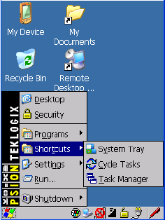
Chapter 4: Working With Windows Embedded CE 5.0
Shortcuts
68 WORKABOUT PRO G2 Hand-Held With Windows Embedded CE 5.0 User Manual
4.4.4 Shortcuts
Figure 4.10 Shortcuts Sub-Menu
System Tray
If your touchscreen is not enabled, you can use the System Tray option to access the
icons in the taskbar at the bottom of the screen. The taskbar displays indicators such
as a radio signal icon and the security level. These indicators are attached to dialog
boxes that provide additional information.
• Choose Shortcuts>System Tray.
When System Tray is chosen, the taskbar icons become accessible. To display the
dialog box attached to an icon:
• Use the arrow keys to highlight an icon, for example, the security icon.
• Press [ENTER] to display the security level dialog box.
Cycle Tasks
When Cycle Tasks is selected (and the Task Manager is not open), you can cycle
through active applications.
To cycle through your active applications:
• Choose Shortcuts>Cycle Tasks, or
Press [ALT] [TAB].
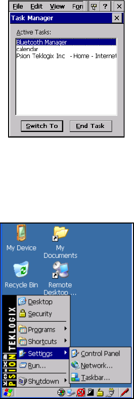
WORKABOUT PRO G2 Hand-Held With Windows Embedded CE 5.0 User Manual 69
Chapter 4: Working With Windows Embedded CE 5.0
Settings
Task Manager
The Task Manager allows you to switch to another task or to end an active task. To
display the task manager window:
• Tap on Shortcuts>Task Manager, or
Press [ALT] [ESC].
Figure 4.11 Task Manager
4.4.5 Settings
The Settings sub-menu includes the following settings: Control Panel, Network
and Dial-up Connections and Taskbar and Start Menu.
Figure 4.12 Settings Sub-Menu
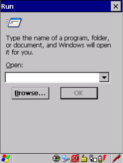
Chapter 4: Working With Windows Embedded CE 5.0
Run
70 WORKABOUT PRO G2 Hand-Held With Windows Embedded CE 5.0 User Manual
Control Panel
The Control Panel contains applets used to configure hardware, the operating
system and the shell. If your WORKABOUT PRO G2 is running with the Psion
Teklogix TekTerm application or another application, additional configuration
applets may appear in the Control Panel.
Network And Dial-Up Connections
The Network and Dial-up Connections window allows you to configure the
WORKABOUT PRO G2 radio or execute an existing configuration. Refer to
“Configuring Your Radio” on page 13 for radio setup details.
Taskbar And Start Menu
The Taskbar and Start Menu option displays a dialog box in which you can
customize the taskbar, choosing which options will be displayed. Refer to
“Customizing The Taskbar” on page 62 for additional details about this option.
4.4.6 Run
Choosing the Run option from the Start Menu displays a dialog box in which you
can enter the name of the program, folder or document you want to open or launch.
Figure 4.13 Run Dialog Box
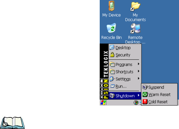
WORKABOUT PRO G2 Hand-Held With Windows Embedded CE 5.0 User Manual 71
Chapter 4: Working With Windows Embedded CE 5.0
Shutdown
4.4.7 Shutdown
The Shutdown menu includes these options: Suspend, Warm Reset and Cold Reset.
Figure 4.14 Shutdown Sub-Menu
Note: This menu varies slightly depending on the security level chosen. When
the WORKABOUT PRO G2 is set to User level, the Shutdown option is
replaced by Suspend. A sub-menu is not available.
Suspend
The Suspend option suspends the WORKABOUT PRO G2 immediately. This is
equivalent to turning the hand-held off.
Warm Reset
The Warm Reset option resets the WORKABOUT PRO G2, leaving all saved files
and (registry) settings intact. Any unsaved data is lost.
Cold Reset
The Cold Reset option resets the WORKABOUT PRO G2 (see page 31). Any files
not stored in permanent memory are lost; however, the registry settings are saved.
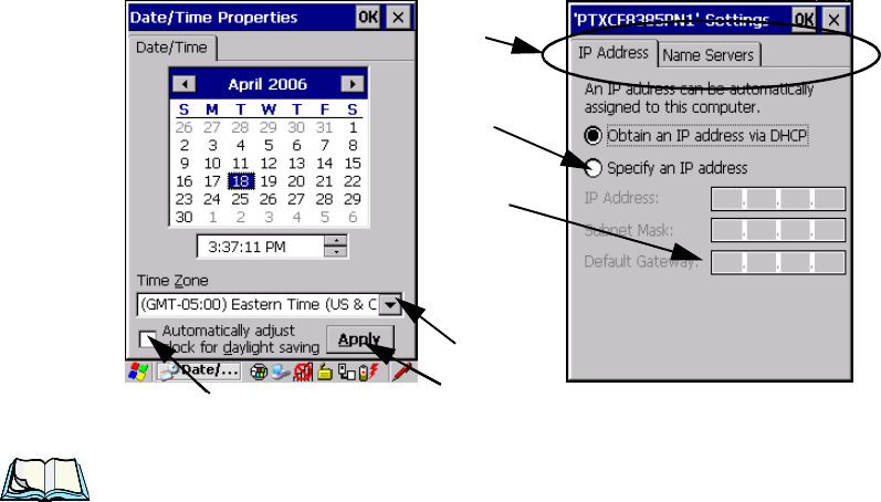
Chapter 4: Working With Windows Embedded CE 5.0
Using A Dialog Box
72 WORKABOUT PRO G2 Hand-Held With Windows Embedded CE 5.0 User Manual
4.5 Using A Dialog Box
A dialog box (like the samples in Figure 4.15) appears when you need to make
selections and enter further information. You can move between dialog items by
tapping on them with your stylus, or by pressing the arrow keys and the [TAB] key
([SHIFT] [TAB] moves the cursor backwards).
Figure 4.15 Dialog Boxes
Note: You can use the stylus to tap on an element in a dialog box to select or
deselect it, display drop-down menu items, save your selections, and
so on.
Dialog boxes contain one or more of the following elements:
Tab: A tab separates different elements of a dialog box. Press the [TAB] key until a
tab in the dialog box is highlighted. To display adjoining tabs, press the [RIGHT] or
[LEFT] arrow key. To display the information in the next tab from anywhere in the
window, press [CTRL] [TAB].
Textbox: A textbox requires that you type information. Press the [TAB] key to
highlight the textbox and then type the appropriate information.
Drop-down: This type of menu is identified by up and down arrows next to the
drop-down menu to indicate that additional options are available. Press the [TAB]
key to highlight the menu, and use the arrow keys on your keyboard to cycle
through the options.
Checkbox
Drop-down Menu
Button
Textbox
Radio
Button
Tabs

WORKABOUT PRO G2 Hand-Held With Windows Embedded CE 5.0 User Manual 73
Chapter 4: Working With Windows Embedded CE 5.0
Using A Dialog Box
Checkbox: This box allows you to select or deselect an option. To select or deselect
a checkbox, press the [TAB] key to highlight the checkbox, and press the [SPACE]
key to select or deselect it.
Radio buttons: These buttons allow you to choose from a number of options. For
example, in the sample screen in Figure 4.15 on page 72 you can choose to Obtain
an IP address via DHCP or Specify an IP address. Press the [TAB] key to highlight
a radio button option, and then select a radio button by pressing the arrow keys to
highlight the appropriate option.
Buttons: This type of button allows you to Save, Delete and so on the options
you’ve chosen in a dialog box. Use the [TAB] key to highlight the button you want
to use. Press the [ENTER] key to activate it.
Saving Your Choices: Once you’ve made all your changes, press the [ENTER] key
to save your changes and exit the window.
Note: A dialog box item that is displayed in grey text indicates that it is not
currently available.

WORKABOUT PRO G2 Hand-Held With Windows Embedded CE 5.0 User Manual 75
CONFIGURATION 5
5.1 Remote Connect...............................81
5.2 The TekTerm Application..........................81
5.3 Pocket PC Compatibility..........................81
5.4 The Control Panel..............................81
5.5 Control Panel Icons.............................83
5.6 Basic Setup.................................87
5.6.1 Display Properties ..........................87
5.6.1.1 Display Backlight......................87
5.6.1.2 Display Appearance.....................89
5.6.2 Keyboard Properties . . . . . . . . . . . . . . . . . . . . . . . . . 90
5.6.2.1 Key Repeat..........................90
5.6.2.2 Keyboard Backlight.....................91
5.6.2.3 Keyboard One Shot Modes.................92
5.6.2.4 Keyboard Macro Keys....................93
5.6.2.5 Unicode Mapping......................95
5.6.2.6 Scancode Remapping....................97
5.6.3 Volume And Sound Properties . . . . . . . . . . . . . . . . . . . . 99
5.6.3.1 Volume Adjustments.....................100
5.6.4 Power Management Properties....................100
5.6.4.1 Battery Capacity.......................101
5.6.4.2 Power Saving Suspend....................101
5.6.4.3 Suspend Threshold......................102
5.6.4.4 Advanced ..........................103
5.6.4.5 Devices............................104
5.6.5 Stylus Properties...........................104
5.6.5.1 Double-Tap . . . . . . . . . . . . . . . . . . . . . . . . .105
5.6.5.2 Calibration..........................105
5.6.5.3 Touch ............................105
5.6.6 Manage Triggers...........................106
5.6.6.1 Trigger Mappings......................107
5.6.6.2 Add And Edit Trigger Mapping . . . . . . . . . . . . . . .108
5.6.7 Certificate Assignment........................110
5.7 Bluetooth Setup...............................111
Chapter 5: Configuration
76 WORKABOUT PRO G2 Hand-Held With Windows Embedded CE 5.0 User Manual
5.7.1 The Devices Tab...........................112
5.7.2 The Servers Tab...........................115
5.7.3 Outgoing Tab............................116
5.7.4 Active Conn. Tab..........................117
5.7.5 The Properties Tab .........................118
5.7.6 The Bluetooth GPRS WAN Connection . . . . . . . . . . . . . . 118
5.8 Total Recall................................124
5.8.1 Creating A Backup Profile . . . . . . . . . . . . . . . . . . . . . 125
5.8.2 Restoring A Profile.........................129
5.9 The Storage Manager...........................129
5.9.1 Formatting A Memory Card ....................129
5.9.2 Creating Partitions .........................130
5.9.3 Partition Management........................132
5.10 IPv6 Support . . . . . . . . . . . . . . . . . . . . . . . . . . . . . . . 134
5.11 Scanner Settings.............................135
5.11.1 Bar Codes.............................136
5.11.1.1 Scanner..........................136
5.11.2 Decoded (Internal) Scanners....................137
5.11.2.1 Options..........................137
5.11.2.2 Decoded (Internal) Advanced Options . . . . . . . . . . 138
5.11.2.3 Decoded (Internal) 2D Scanning Options . . . . . . . . 139
5.11.2.4 Decoded (Internal) 2D Scanning Options . . . . . . . . 140
5.11.2.5 Code 39..........................141
5.11.2.6 Code 128.........................144
5.11.2.7 EAN 13..........................144
5.11.2.8 EAN 8...........................145
5.11.2.9 UPC A...........................145
5.11.2.10 UPC E..........................146
5.11.2.11 UPC/EAN Shared Settings ...............147
5.11.2.12 Code 93.........................148
5.11.2.13 Codabar.........................149
5.11.2.14 MSI Plessey.......................149
5.11.2.15 Interleaved 2 of 5....................150
5.11.2.16 Discrete 2 of 5......................151
5.11.2.17 RSS Code........................152
5.11.2.18 Composite........................152
5.11.2.19 PDF-417.........................153
5.11.2.20 Micro PDF-417.....................153
WORKABOUT PRO G2 Hand-Held With Windows Embedded CE 5.0 User Manual 77
Chapter 5: Configuration
5.11.3 Decoded (HHP)...........................154
5.11.3.1 Decoded (HHP) Scanner Options .............154
5.11.3.2 Decoded (HHP) Advanced Options . . . . . . . . . . . .154
5.11.3.3 Code 39...........................155
5.11.3.4 Trioptic Code........................156
5.11.3.5 Code 128..........................156
5.11.3.6 EAN 13 Settings......................157
5.11.3.7 EAN 8 ...........................158
5.11.3.8 UPC A Settings.......................158
5.11.3.9 UPC E Settings.......................159
5.11.3.10 UPC/EAN Shared Settings................160
5.11.3.11 Code 93..........................160
5.11.3.12 Codabar..........................161
5.11.3.13 MSI Plessey........................162
5.11.3.14 Code 11..........................163
5.11.3.15 Interleaved 2 of 5.....................163
5.11.3.16 Matrix 2 of 5 .......................164
5.11.3.17 IATA 2 of 5........................164
5.11.3.18 Discrete 2 of 5.......................165
5.11.3.19 Telepen..........................165
5.11.3.20 RSS Code (Reduced Space Symbology) . . . . . . . . .166
5.11.3.21 PosiCode (Reduced Space Symbology). . . . . . . . . .167
5.11.3.22 Composite.........................167
5.11.3.23 TLC-39..........................168
5.11.3.24 PDF-417..........................168
5.11.3.25 Micro PDF-417......................169
5.11.3.26 Code 16K.........................169
5.11.3.27 Code 49..........................170
5.11.3.28 Codablock.........................170
5.11.3.29 2D Data Matrix......................170
5.11.3.30 2D QR Code........................171
5.11.3.31 2D Maxicode.......................171
5.11.3.32 2D Aztec .........................172
5.11.3.33 Postal: PlaNET......................172
5.11.3.34 Postal: PostNET......................172
5.11.3.35 Postal: Australian.....................173
5.11.3.36 Postal: Canadian......................173
5.11.3.37 Postal: China.......................173
Chapter 5: Configuration
78 WORKABOUT PRO G2 Hand-Held With Windows Embedded CE 5.0 User Manual
5.11.3.38 Postal: Japanese.....................173
5.11.3.39 Postal: Kix........................174
5.11.3.40 Postal: Korean......................174
5.11.3.41 Postal: Royal.......................174
5.11.4 Decoded (Intermec ISCP).....................175
5.11.4.1 Decoded (Intermec ISCP) Options . . . . . . . . . . . . 175
5.11.4.2 Decoded (Intermec ISCP) Advanced Options . . . . . . 175
5.11.4.3 Code 39..........................176
5.11.4.4 Code 128.........................178
5.11.4.5 EAN 13 Settings .....................179
5.11.4.6 EAN 8...........................180
5.11.4.7 UPC A Settings......................180
5.11.4.8 UPC E Settings......................181
5.11.4.9 UPC/EAN Shared Settings................181
5.11.4.10 Code 93.........................182
5.11.4.11 Codabar.........................183
5.11.4.12 MSI Plessey.......................184
5.11.4.13 Code 11.........................185
5.11.4.14 Interleaved 2 of 5....................185
5.11.4.15 Matrix 2 of 5.......................186
5.11.4.16 Discrete 2 of 5......................187
5.11.4.17 Telepen..........................188
5.11.4.18 RSS Code (Reduced Space Symbology) . . . . . . . . 188
5.11.4.19 PDF-417.........................189
5.11.4.20 Micro PDF-417.....................189
5.11.4.21 Codablock........................190
5.11.5 Imager...............................190
5.11.5.1 Imager Options......................190
5.11.5.2 Imager Advanced Options................192
5.11.5.3 Code 39 Settings.....................194
5.11.5.4 Code 128 Settings.....................194
5.11.5.5 EAN 13..........................195
5.11.5.6 EAN 8...........................195
5.11.5.7 UPC A...........................196
5.11.5.8 UPC E...........................196
5.11.5.9 Code 93..........................196
5.11.5.10 Codabar.........................196
5.11.5.11 Interleaved 2 of 5....................197
WORKABOUT PRO G2 Hand-Held With Windows Embedded CE 5.0 User Manual 79
Chapter 5: Configuration
5.11.5.12 RSS Code (Reduced Space Symbology) . . . . . . . . .197
5.11.5.13 Composite.........................197
5.11.5.14 PDF-417..........................197
5.11.5.15 Micro PDF-417......................198
5.11.5.16 2D Data Matrix......................198
5.11.5.17 2D QR Code........................198
5.11.5.18 2D Maxicode.......................198
5.11.5.19 2D Aztec .........................198
5.11.5.20 Postal: PlaNET......................199
5.11.5.21 Postal: PostNET......................199
5.11.5.22 Postal: Australian.....................199
5.11.5.23 Postal: Japanese......................199
5.11.5.24 Postal: Korean.......................200
5.11.5.25 Postal: Royal.......................200
5.11.6 Options ...............................200
5.11.6.1 Double Click Parameters..................201
5.11.6.2 Display Parameters.....................201
5.11.7 Translations Tab...........................203
5.11.7.1 Case Rules.........................205
5.12 SNMP (Simple Network Management Protocol) Setup. . . . . . . . . .205
5.12.1 Contact Tab.............................206
5.12.2 Communities Tab..........................207
5.12.2.1 Adding A Community...................207
5.12.2.2 Modifying A Community Setting . . . . . . . . . . . . .208
5.12.2.3 Removing An Existing Community . . . . . . . . . . . .208
5.12.3 Trap Destination Tab........................209
5.12.3.1 Enabling Authentication TRAPS. . . . . . . . . . . . . .209
5.12.3.2 Adding A Destination...................209
5.12.3.3 Changing A Destination..................209
5.12.3.4 Removing A Trap Destination...............210
5.12.4 Permitted Hosts Tab.........................210
5.12.4.1 Adding A Host.......................211
5.12.4.2 Changing A Host......................211
WORKABOUT PRO G2 Hand-Held With Windows Embedded CE 5.0 User Manual 81
Chapter 5: Configuration
Remote Connect
5.1 Remote Connect
Remote Connect is a WORKABOUT PRO G2 application used to connect to a
Windows Terminal Server so that you can run a “session” on the Server machine,
using the WORKABOUT PRO G2 (Windows Embedded CE 5.0 device).
Refer to the following website for step-by-step information about setting up this
connection:
http://www.microsoft.com/WindowsXP/pro/using/howto/gomobile/remotedesktop/default.asp,
or contact Psion Teklogix support services. (Refer to WORKABOUT PRO
Hand-Held Computer Regulatory & Warranty Guide, PN 8000126, or locate the
office closest to you at www.psionteklogix.com).
5.2 The TekTerm Application
TekTerm is a powerful emulation application ideally suited for real time data
transaction applications associated with mainframes and servers. The
WORKABOUT PRO G2 includes unique features that support TekTerm—a Psion
Teklogix application that has the ability to maintain multiple simultaneous sessions
with a variety of host computers. For detailed information, please refer to the
TekTerm Software User Manual, PN 8000073.
5.3 Pocket PC Compatibility
The WORKABOUT PRO G2 supports the AYGShell API set that allows Pocket
PC-compatible applications to run on the hand-held. Windows Embedded CE 5.0
includes application programming interface (API) compatibility support for the
Microsoft Windows Powered Pocket PC 2002 shell in units running Windows
Embedded CE 5.0.
The website listed below describes the APIs exposed through AYGShell and the
application compatibility between Windows Powered Pocket PC 2002-based
applications and Windows Embedded CE 5.0-based devices:
http://msdn.microsoft.com/library/default.asp?url=/library/en-us/dncenet/html/WINCENET_CEPCC_App.asp
5.4 The Control Panel
The Windows Embedded CE 5.0 Control Panel provides a group of icons through
which you can set a variety of system-wide properties, such as mouse sensitivity,
network configuration and the desktop color scheme.
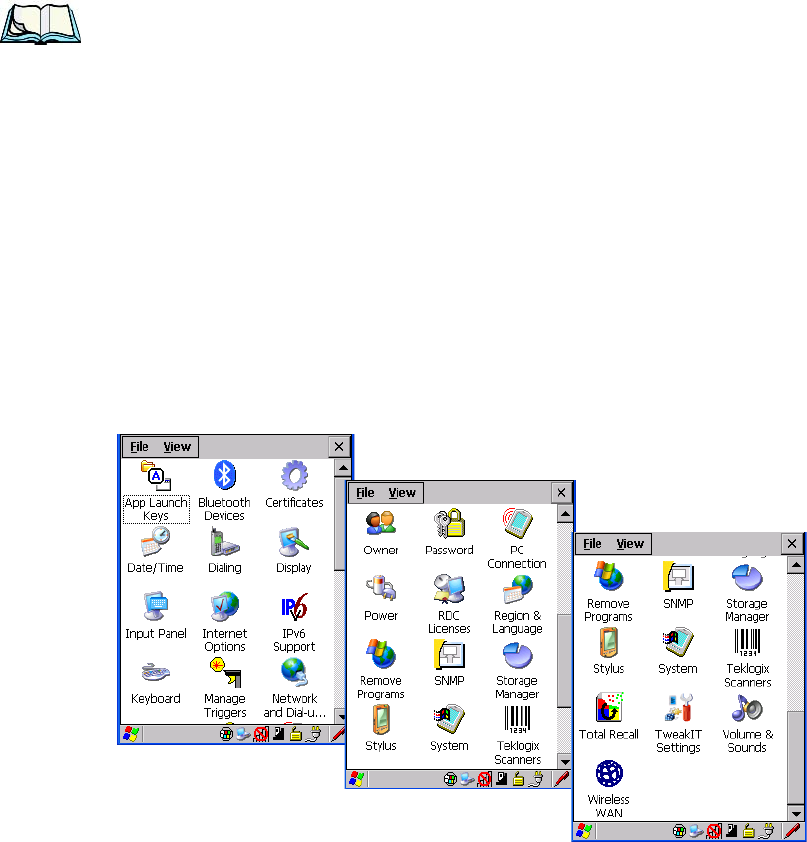
Chapter 5: Configuration
The Control Panel
82 WORKABOUT PRO G2 Hand-Held With Windows Embedded CE 5.0 User Manual
Note: If you are uncertain how to move around a dialog box and make selec-
tions, review “Using A Dialog Box” on page 72.
When the WORKABOUT PRO G2 boots up, the startup desktop (shell) is
displayed, and any applications stored in the Startup folder start up immediately.
To access the Control Panel:
• Tap on Start>Settings>Control Panel.
If you’re using the keyboard:
• Press [FN/BLUE] [.] to display the Start Menu.
• Highlight Settings in Start Menu, and press the [RIGHT] arrow key to
highlight the Control Panel.
• Press the [ENTER] key.
The Control Panel folder contains icons used in the setup of your WORKABOUT
PRO G2.
Figure 5.1 Control Panel
WORKABOUT PRO G2 Hand-Held With Windows Embedded CE 5.0 User Manual 83
Chapter 5: Configuration
Control Panel Icons
5.5 Control Panel Icons
The Control Panel provides a group of icons that allow you to customize and adjust
settings on your WORKABOUT PRO G2.
App Launch Keys
By mapping keys to applications using this program, you can then launch
those applications from a single key-press.
Bluetooth Devices
Provides options for Bluetooth radio setup. It also provides the capability to
use a Bluetooth-enabled cellular phone as a data modem to exchange infor-
mation with other Bluetooth devices and provide network access.
Certificates
A public key is transmitted as part of a certificate. The certificate assigned
through this icon is used to ensure that the submitted public key is, in fact,
the public key that belongs to the submitter. The client checks that the cer-
tificate has been digitally signed by a certification authority that the client
explicitly trusts. “Certificate Assignment” on page 110 directs you to the
appropriate setup information.
Date/Time
Allows you to set the current Month, Date, Time and Time Zone on
your unit.
Dialing Specifies dialing settings, including area code, country code, dial type and
the code to disable call waiting. You can store multiple patterns—
for example, ‘Work’, ‘Home’, and so on using this dialog box.
Display Changes the appearance (window colour scheme) on the unit desktop.
Input Panel
Provides the framework for a Soft Input Panel (SIP) should you need to
design your own SIP, or change some soft keyboard options.

Chapter 5: Configuration
Control Panel Icons
84 WORKABOUT PRO G2 Hand-Held With Windows Embedded CE 5.0 User Manual
Internet Options
Provides options to configure your Internet browser. You can determine
items such as the default and search page that the browser applies when
connecting to the Internet, the cache size, the Internet connection options,
and the security level that is applied when browsing.
IPv6 Support
Refers to a new Internet Protocol specification (version 6) that has been
published to use 128-bit IP addresses (replacing version 4).
Keyboard
Toggles character repeat on and off and specifies delay and rate for repeated
characters. It also allows you to adjust the keyboard backlight threshold and
intensity.
Manage Triggers
Allows multiple-scanner trigger management, including the ability to con-
figure each of the trigger buttons. You can configure the trigger ID for each
trigger button for both single- and double-click, and the double-click time.
Network And Dial-up Connections
Displays a network window from which the WORKABOUT PRO G2
802.11g radio can be configured and an existing configuration can be exe-
cuted. Refer to “Configuring Your Radio” on page 13 for details.
Owner Provides fields in which you can specify owner information. A Notes tab
allows additional information to be entered and displayed when the unit is
powered up. Network ID tab information is used to access network resources.
(This information should be provided by your System Administrator.)
Password
Allows you to assign a password to restrict access to elements of the unit.
Once assigned, password access cannot be circumvented so it is important
that you write down your password and keep it in a safe place. Refer to
“Security Settings” on page 64 for details.
WORKABOUT PRO G2 Hand-Held With Windows Embedded CE 5.0 User Manual 85
Chapter 5: Configuration
Control Panel Icons
PC Connection
Enables direct connections to a desktop computer. Selecting the Change
Connection button allows you to change the type of direct connect to
your PC.
Power Displays battery pack power status. (Alternately, battery status can be
accessed through the taskbar.) Additional tabs allow you to determine
suspend states, specify a suspend threshold and, when seated in either the
Combo Dock or Quad Dock, determine whether or not a battery that
requires it can be recalibrated. This dialog box also allows you to activate
card slots. (Refer to “Devices” on page 104 for details.)
RDC Licenses
The Terminal Services license server stores all license tokens that have been
installed for a group of terminal servers and tracks licenses issued. The
Remote Desktop Licenses (RDC) application displays license ‘tokens’ for
devices that connect to a Terminal Server.
Region & Language
Allows you to specify the local language that is to be displayed on the
hand-held screen along with the format of numbers, currency, time and date
for your region.
Remove Programs
Lists the programs that can be removed from your unit. To remove a pro-
gram, select it and then click on the Remove button.
SNMP SNMP (Simple Network Management Protocol) is the protocol used to
monitor and manage devices attached to a TCP/IP network.
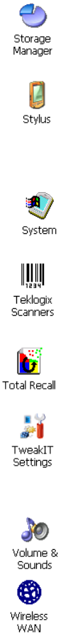
Chapter 5: Configuration
Control Panel Icons
86 WORKABOUT PRO G2 Hand-Held With Windows Embedded CE 5.0 User Manual
Storage Manager
Allows the user to view information about the storage devices that are
present, such as SD-MMC flash cards. For details, see page 129.
Stylus Adjusts how Windows Embedded CE 5.0 recognizes your double-tap (as
slow or rapid successive taps). In the Calibration tab, you can recalibrate
your touchscreen by tapping on the Recalibrate button and following the
directions on the screen.
System Displays system and memory properties. In the Memory tab, you can allo-
cate memory between storage memory and program memory.
Teklogix Scanners
Provides scanner parameters and the bar code symbologies that the WORK-
ABOUT PRO G2 scanner will successfully read.
Total Recall
Provides access to a backup and restore utility to maintain applications and
settings over cold reboots.
TweakIT Settings
Allows you to change Advanced System Settings (interface, network, and
servers), User System Settings (display font size), and provides the
Registry Editor.
Volume & Sounds
Allows you to adjust the volume of the sound emitted to indicate events like
warnings, key clicks and screen taps.
Wireless WAN
Provides access to technology like GSM/GPRS, which allows wide area
networking capability such as internet browsing via GSM/GPRS. For
detailed information, see Appendix B: “Wireless WAN”.
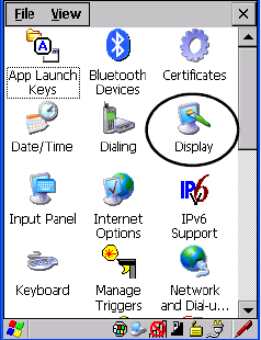
WORKABOUT PRO G2 Hand-Held With Windows Embedded CE 5.0 User Manual 87
Chapter 5: Configuration
Basic Setup
5.6 Basic Setup
5.6.1 Display Properties
•In the Control Panel, choose the Display icon.
Figure 5.2 Choosing The Display Icon
5.6.1.1 Display Backlight
The backlight is activated for a configurable amount of time when the
WORKABOUT PRO G2 is in use (key press, scanner trigger or data received from
the host). The Display Properties dialog box in the Control Panel allows you to
specify the intensity of the backlight along with how long the display will maintain
the specified intensity.
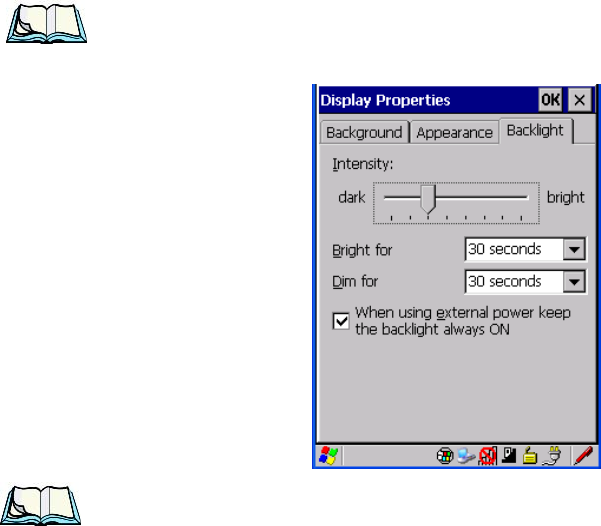
Chapter 5: Configuration
Display Properties
88 WORKABOUT PRO G2 Hand-Held With Windows Embedded CE 5.0 User Manual
Note: Keep in mind that this option may be restricted to supervisory use only.
•In the Display Properties dialog box, open the Backlight tab.
Notes: Backlight changes take effect immediately. You do not need to reset the
unit.
To maximize battery run time, keep the display backlight brightness and
active durations as low as possible.
Intensity
This parameter is used to adjust the light intensity of the WORKABOUT PRO G2
backlight. Sliding the bar to the left lowers the light intensity, and sliding it to the
right raises the intensity.
Bright For
The value chosen from this drop-down menu determines the duration of time that
the backlight stays on at the configured intensity after the last user action (keypress,
scan trigger).
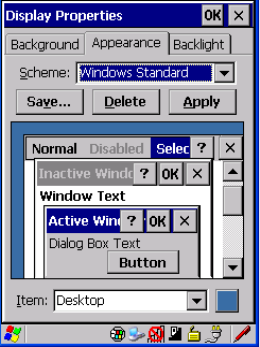
WORKABOUT PRO G2 Hand-Held With Windows Embedded CE 5.0 User Manual 89
Chapter 5: Configuration
Display Properties
Dim For
The value chosen from this drop-down menu determines the duration of time that
the backlight stays on at half the configured intensity (dimmed backlight) after
expiration of the Bright For delay and as long as no user action takes place (such as
a keypress or scan trigger). At the expiration of the Dim For duration, the display
backlight shuts off.
External Power Checkbox
When you select the checkbox next to When using external power keep the
backlight always ON, the backlight remains ON at the configured intensity when
the WORKABOUT PRO G2 is operating with external power (not battery power).
If the WORKABOUT PRO G2 is drawing power from its battery, this option is
ignored and the other parameters defined in Display Properties dialog box are used.
5.6.1.2 Display Appearance
•In the Display Properties dialog box, open the Appearance tab.
This dialog box allows you to customize the display colour scheme.
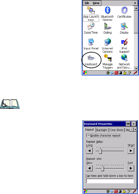
Chapter 5: Configuration
Keyboard Properties
90 WORKABOUT PRO G2 Hand-Held With Windows Embedded CE 5.0 User Manual
5.6.2 Keyboard Properties
This icon displays the Keyboard Properties dialog box in which you can adjust the
repeat rate of the keys, the intensity of the keyboard backlight and the behaviour of
the [BLUE] and [ORANGE] modifier keys. This dialog box also allows you to
define macro keys and Unicode characters.
•In the Control Panel, choose the Keyboard icon.
Figure 5.3 Choosing The Keyboard Icon
5.6.2.1 Key Repeat
Note: These settings apply when a key is held down continuously.
•In the Keyboard Properties dialog box, open the Repeat tab.
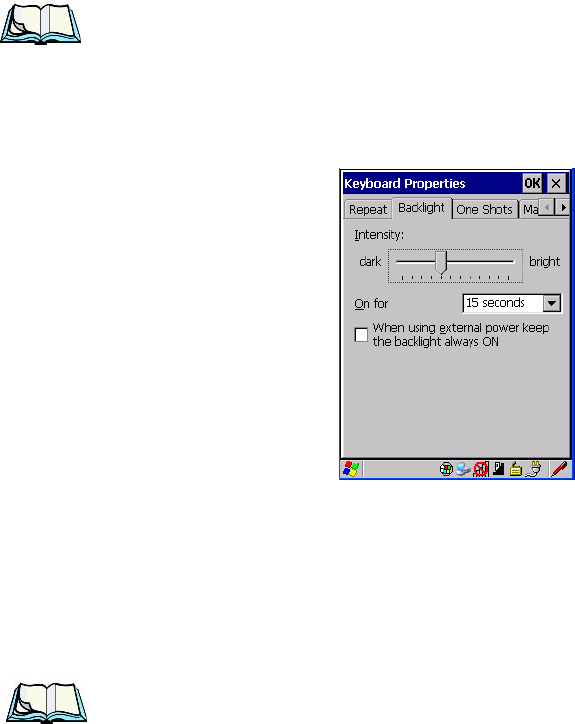
WORKABOUT PRO G2 Hand-Held With Windows Embedded CE 5.0 User Manual 91
Chapter 5: Configuration
Keyboard Properties
Repeat Delay
The value assigned for this parameter determines the delay in milliseconds between
repeat characters. Sliding the Repeat Delay bar to the left increases the delay
between key repeats, and sliding the bar to the right shortens the repeat delay time.
Repeat Rate
The value assigned for the Repeat Rate parameter determines how quickly the key
you press repeats and is measured in characters per second (cps). Sliding the bar to
the left slows the repeat rate, and sliding the bar to the right increases the repeat rate.
Note: Use the field at the bottom of this dialog box to test the repeat delay and
rate settings you’ve chosen.
5.6.2.2 Keyboard Backlight
•In the Keyboard Properties dialog box, open the Backlight tab.
This parameter is used to adjust the light intensity of the WORKABOUT PRO G2
keyboard backlight. Sliding the bar to the left darkens the keyboard backlight
intensity, and sliding it to the right lightens the intensity.
ON For
The value chosen from this dropdown menu determines the duration of time that the
keyboard backlight stays on when a unit is not in use.
Note: Tapping in the checkbox next to ‘When using external power, keep the
backlight always ON’ forces the keypad backlight to remain on when the
unit is operating with external power.
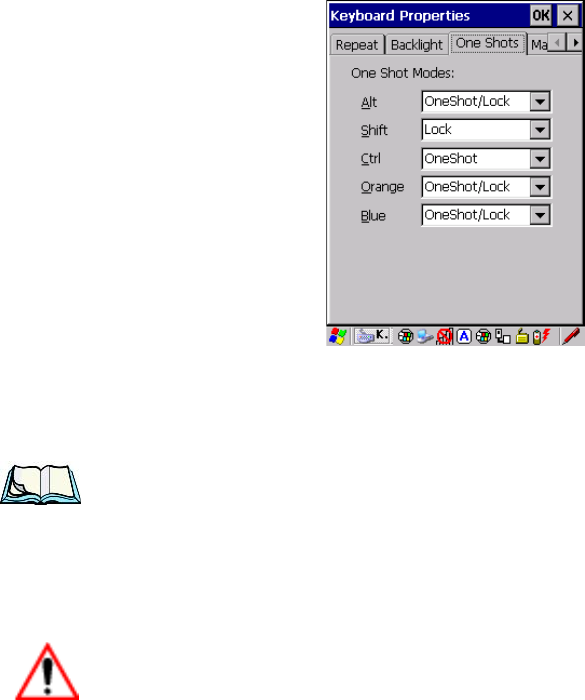
Chapter 5: Configuration
Keyboard Properties
92 WORKABOUT PRO G2 Hand-Held With Windows Embedded CE 5.0 User Manual
5.6.2.3 Keyboard One Shot Modes
• In the Keyboard Properties dialog box, open the One Shots tab.
The options in this tab allow you to determine how modifier keys on your
WORKABOUT PRO G2 behave. For each modifier key—[ALT], [SHIFT],
[CTRL], [ORANGE] and [BLUE]—you have the following options in the
drop-down menu: Lock, OneShot, and OneShot/Lock.
Note: Keep in mind that checking the taskbar lets you know whether or not
these keys are locked on. For example, if the [FN/ORANGE] key is locked
‘on’, the taskbar at the bottom of the screen displays it in uppercase char-
acters, ORANGE KEY. If this key is displayed in lowercase characters in the
taskbar, you’ll know that the orange key is not locked. It will become inac-
tive following a key press.
Important: Once you’ve assigned a One Shot mode to a modifier key, you need
to tap on the OK button at the top of the tab to activate your selec-
tion.
Lock
If you choose Lock from the drop-down menu, pressing a modifier key once locks it
‘on’ until you press the modifier key a second time to unlock or turn it off.
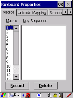
WORKABOUT PRO G2 Hand-Held With Windows Embedded CE 5.0 User Manual 93
Chapter 5: Configuration
Keyboard Properties
OneShot
If you choose OneShot, the modifier key remains active only until the next key is
pressed.
OneShot/Lock
OneShot/Lock allows you to combine these functions. When you choose this
option and you press the modifier key once, it remains active only until the next key
is pressed.
If you press the modifier key twice, it is locked ‘on’, remaining active until the
modifier key is pressed a third time to turn it ‘off’.
5.6.2.4 Keyboard Macro Keys
•In the Keyboard Properties dialog box, open the Macros tab.
A macro has 200 programmable characters (or “positions”). The macro keys can be
programmed to replace frequently used keystrokes, along with the function of
executable keys including [ENTER], [BKSP] and [DEL] ([FN/BLUE]-[BKSP]),
function keys and arrow keys.
Recording And Saving A Macro
You can program up to 12 macro keys on a 58-key WORKABOUT PRO G2. On a
36-key WORKABOUT PRO G2, you can program a maximum of 6 macro keys.
•In the Macro menu highlight a macro key number, for example macro 1, to
assign a macro to macro key [M1]. Choose the Record button.
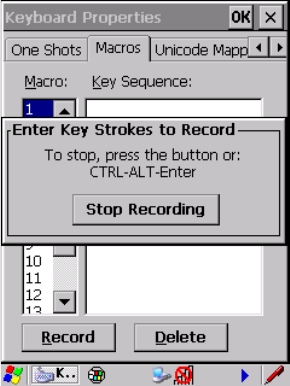
Chapter 5: Configuration
Keyboard Properties
94 WORKABOUT PRO G2 Hand-Held With Windows Embedded CE 5.0 User Manual
A message screen is displayed instructing you to Enter Key Strokes to Record
• Type the macro sequence you want to assign to the Macro key. You can
type text and numbers, and you can program the function of special keys
into a macro.
• When you’ve finished recording your macro sequence, press the key
sequence: [CTRL] [ALT] [ENTER], or choose the Stop Recording button.
A new screen called ‘Verify Macro’ displays the macro sequence you created.
The Save button is highlighted.
• Press [ENTER] to save your macro, or highlight CANCEL and press
[ENTER] to discard it.
Executing A Macro
To execute a macro:
• Press the macro key to which you’ve assigned the macro. For example, if
you created a macro for macro key 1, press [M1] to execute the macro.
Deleting A Macro
To delete a macro:
•In the Macros tab, highlight the macro number you want to delete.
• Choose the Delete button.
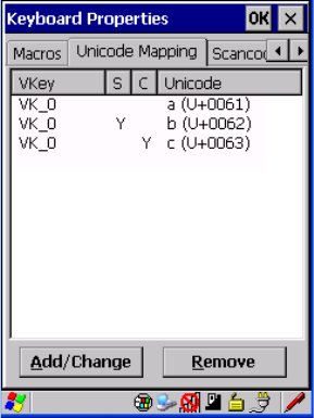
WORKABOUT PRO G2 Hand-Held With Windows Embedded CE 5.0 User Manual 95
Chapter 5: Configuration
Keyboard Properties
5.6.2.5 Unicode Mapping
•In the Keyboard Properties dialog box, open the Unicode Mapping tab.
The Unicode Mapping tab is used to map combinations of virtual key values and
[CTRL] and [SHIFT] states to Unicode™ values. This tab shows the configured
Unicode character along with the Unicode value. For example, the sample screen
above shows “a (U+0061)” indicating that the character “a” is represented by the
Unicode value “0061”, and so on. Keep in mind that Unicode configurations are
represented as hexadecimal rather than decimal values.
All user-defined Unicode mappings are listed in the Unicode Mapping tab in order
of virtual key value, and then by order of the shift state. If a Unicode mapping is not
listed, the Unicode mapping is mapped to the default Unicode value.
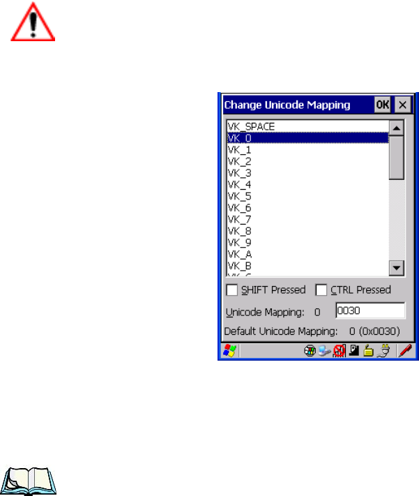
Chapter 5: Configuration
Keyboard Properties
96 WORKABOUT PRO G2 Hand-Held With Windows Embedded CE 5.0 User Manual
Adding And Changing Unicode Values
Important: Changes to Unicode mappings are not saved until you exit the
Keyboard Properties dialog box.
• Choose the Add/Change button.
Figure 5.4 Adding And Change Unicode Values
• Highlight a value in the Unicode mapping list. In the sample screen above,
a value will be assigned to virtual key 0 (VK 0).
• Position the cursor in the Unicode Mapping field, and type a Unicode
value for the highlighted key.
Note: To add a shifted state, [SHIFT] and/or [CTRL], press [TAB] to position
the cursor in the checkbox next to ‘SHIFT Pressed’ and/or ‘CTRL
Pressed’. Press [SPACE] to select the shift state you want to assign.
Removing Unicode Values
•In the Unicode Mapping tab, highlight the item you want to delete, and
choose the Remove button.
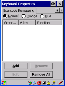
WORKABOUT PRO G2 Hand-Held With Windows Embedded CE 5.0 User Manual 97
Chapter 5: Configuration
Keyboard Properties
5.6.2.6 Scancode Remapping
A scancode is a number that is associated with a physical key on a keyboard. Every
key has a unique scancode that is mapped to a virtual key, a function or a macro.
Scancode Remapping allows you to change the functionality of any key on the
keyboard. A key can be remapped to send a virtual key (e.g. VK_F represents the
‘F’ key; VK_RETURN represents the [ENTER/ON] key, etc.), perform a function
(e.g. turn the scanner on, change volume/contrast, etc.) or run a macro.
There are three different tables of scancode mappings: the Normal table, the Blue
table and the Orange table. The Normal table defines unmodified key presses; the
Blue table defines key presses that occur when the [FN/BLUE] modifier is on; the
Orange table defines key presses that occur when the [FN/ORANGE] modifier is
on. The default mappings of these scancodes can be overwritten for each of these
three tables using the Scancode Remapping tab accessed from the Keyboard
Properties dialog box.
The first column in the Scancode Remapping tab displays the scancodes in
hexadecimal. If the scancode is remapped to a virtual key, that virtual key is
displayed in the next column labelled ‘V-Key’. A virtual key that is ‘Shifted’ or
‘Unshifted’ is displayed in the third column labelled ‘Function’.
If the scancode is remapped to a function or a macro, the first and second columns
remain blank while the third column contains the function name or macro key
number (e.g., Macro 2).
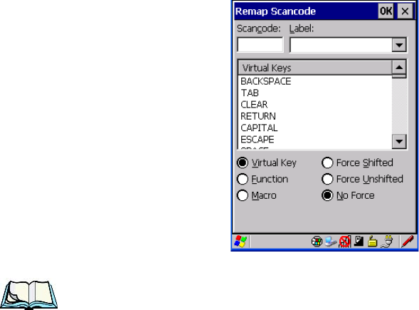
Chapter 5: Configuration
Keyboard Properties
98 WORKABOUT PRO G2 Hand-Held With Windows Embedded CE 5.0 User Manual
Adding A Remap
To add a new remapping:
• Choose the Add button at the bottom of the dialog box.
The Remap Scancode dialog box is displayed.
• Type the scan code in hexadecimal in the field labelled Scancode
Note: The Label field displays the default function of the scancode you
are remapping.
Virtual Key, Function And Macro
The radio buttons at the bottom of the dialog box allow you to define to what the
scan code will be remapped: Virtual Key, Function or Macro.
When Virtual Key is selected, you can choose to force [SHIFT] to be on or off when
the virtual key is sent. If No Force is selected, the shift state is dependent on
whether the shift state is on or off at the time the virtual key is sent.
When Function is selected, a list of valid functions appears in the dialog box.
When Macro is selected, the macro keys available on your unit are listed in the
dialog box.
• Choose Virtual Key, Function or Macro.
• Choose a function from the Function list in the dialog box, and tap on OK.
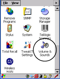
WORKABOUT PRO G2 Hand-Held With Windows Embedded CE 5.0 User Manual 99
Chapter 5: Configuration
Volume And Sound Properties
Editing A Scancode Remap
To edit a scancode:
•In the Scancode Remapping tab, tap the stylus on the remap you want
to edit.
• Tap on the Edit button, and make the appropriate changes.
• Tap on OK to save your changes.
Removing A Remap
To delete a remap:
•In the Scancode Remapping tab, highlight the scancode you want to delete, and
tap on the Remove button.
• Tap on OK.
5.6.3 Volume And Sound Properties
•In the Control Panel, choose the Volume & Sounds icon.
Figure 5.5 Choosing The Volume Icon
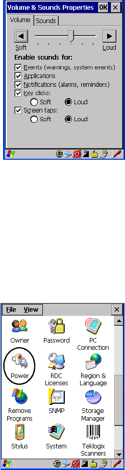
Chapter 5: Configuration
Power Management Properties
100 WORKABOUT PRO G2 Hand-Held With Windows Embedded CE 5.0 User Manual
5.6.3.1 Volume Adjustments
• Slide the volume button to the left to lower the beeper volume or to the right
to increase the beeper volume.
• Under the heading Enable sounds for, enable the conditions under which
you want the WORKABOUT PRO G2 to emit a beep.
5.6.4 Power Management Properties
This icon displays a Power Properties dialog box that indicates the unit’s battery
capacity and allows you to manage battery use.
•In the Control Panel, choose the Power icon.
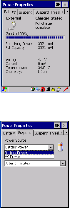
WORKABOUT PRO G2 Hand-Held With Windows Embedded CE 5.0 User Manual 101
Chapter 5: Configuration
Power Management Properties
5.6.4.1 Battery Capacity
•In the Power Properties dialog box, open the Battery tab to view battery
details.
5.6.4.2 Power Saving Suspend
•In the Power Properties dialog box, open the Suspend tab.
Power Source
This drop-down menu allows you to specify whether the unit is using AC Power or
Battery Power.
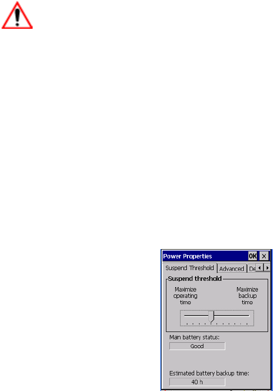
Chapter 5: Configuration
Power Management Properties
102 WORKABOUT PRO G2 Hand-Held With Windows Embedded CE 5.0 User Manual
Suspend Timeout
Important: Psion Teklogix recommends setting the Suspend value to 10 min-
utes. To further reduce power consumption, carefully consider the
duration of time that the display backlight is ‘on’ (see “Display
Backlight” on page 87).
When the WORKABOUT PRO G2 is idle—not receiving any user input (a key
touch, a scan, and so on) or system activity (serial data, an activity initiated by an
application, and so on)—the hand-held uses the value assigned in the Suspend
Timeout field to determine when the unit will go to sleep (appear to be off).
When the time in the Suspend Timeout field elapses without any activity, the unit
enters suspend state. In suspend state, the WORKABOUT PRO G2 CPU enters a
sleep state, and the radio is shut off. The state of the device (RAM contents) is
preserved. Pressing [ENTER] wakes the system from suspend state. When the
WORKABOUT PRO G2 is in suspend state, the network connection will not be
broken immediately. If the connection is dropped, you must re-establish the network
connection.
5.6.4.3 Suspend Threshold
The Suspend Threshold adjustment tells the system when to shut down when the
battery drains. If you choose Maximum Operating Time, the unit will run until the
battery is completely empty; the RAM is only backed up for a short period of time.
If you choose Maximum Backup Time, the hand-held shuts off with more energy left
in the battery so RAM can be backed up for a longer period of time.
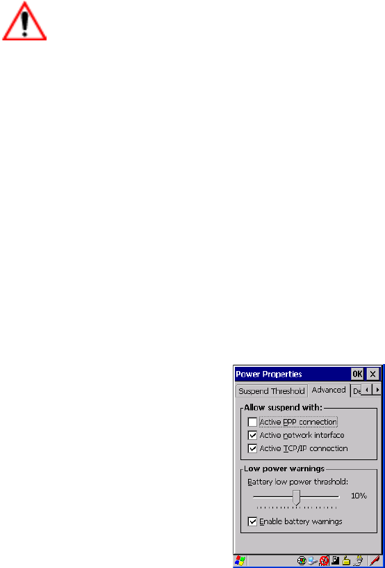
WORKABOUT PRO G2 Hand-Held With Windows Embedded CE 5.0 User Manual 103
Chapter 5: Configuration
Power Management Properties
Important: Selecting Maximum backup time will reserve approximately 20%
of the battery capacity for memory backup. Once the battery is
drained, the system RAM memory is lost and the unit must cold
boot.
In most real-time transaction environments this is not a problem
(it only takes a few seconds to cold boot). Batch transaction envi-
ronments, where data is not saved to a non-volatile memory (such
as an SD FLASH card), may need to pay particular attention to
this parameter. Psion Teklogix does not recommend the storage of
any valuable data in system RAM.
The WORKABOUT PRO G2 normal Windows Embedded CE 5.0
environment does not store any critical data in RAM (such as the
registry or file system).
If the user's application does not save data to RAM, Psion Tek-
logix recommends keeping the Suspend Threshold setting as low
as possible to maximize battery run time.
5.6.4.4 Advanced
Allow Suspend With:
This tab allows you to specify whether or not your unit will enter Suspend state
while it is operating with an active PPP connection, network interface or active
TCP/IP connection.
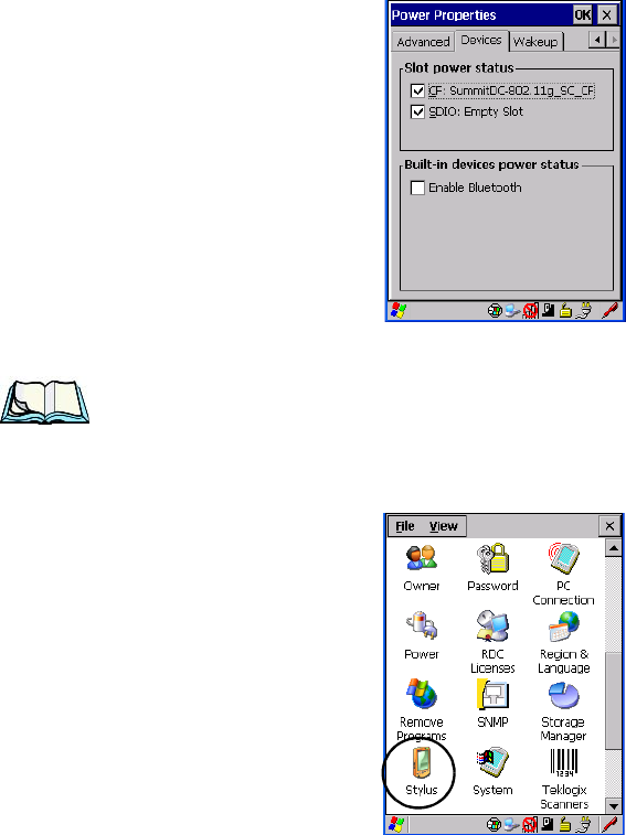
Chapter 5: Configuration
Stylus Properties
104 WORKABOUT PRO G2 Hand-Held With Windows Embedded CE 5.0 User Manual
Low Power Warnings
The sliding scale at the bottom of this tab allows you to specify the remaining
battery capacity at which a warning message is displayed on the WORKABOUT
PRO G2 screen, from 0% to 20%.
5.6.4.5 Devices
This tab controls power to individual CF and SDIO slots, and built-in devices.
Enable or disable the checkboxes as needed, then tap on OK to save your changes.
5.6.5 Stylus Properties
Note: Touchscreen calibration may not be enabled on your unit. If your screen
appears to require recalibration, contact your supervisor.
•In the Control Panel, choose the Stylus icon.
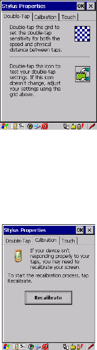
WORKABOUT PRO G2 Hand-Held With Windows Embedded CE 5.0 User Manual 105
Chapter 5: Configuration
Stylus Properties
5.6.5.1 Double-Tap
•In the Double-Tap tab, follow the directions to tailor the sensitivity of the
stylus when you tap on the touchscreen.
5.6.5.2 Calibration
Touchscreens rarely require recalibration. However, if your touchscreen has never
been calibrated or if you find that the stylus pointer is not accurate when you tap on
an item, follow the directions below.
• Choose the Calibration tab, and then tap on the Recalibrate button.
• Follow the directions in the Calibration tab to recalibrate the screen.
5.6.5.3 Touch
This tab allows you to disable the touchscreen.
• Choose the Touch tab. Select the checkbox next to Disable the touch panel.
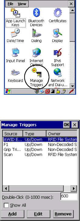
Chapter 5: Configuration
Manage Triggers
106 WORKABOUT PRO G2 Hand-Held With Windows Embedded CE 5.0 User Manual
5.6.6 Manage Triggers
This option allows you to configure how bar code scanners and other devices such
as RFID readers are triggered. You can configure the trigger ID for each trigger
button for both single- and double-click, and the double-click time.
•In the Control Panel, choose the Manage Triggers icon.
Figure 5.6 Manage Triggers Icon
•In the Manage Triggers screen you’ll see a list of trigger mappings.

WORKABOUT PRO G2 Hand-Held With Windows Embedded CE 5.0 User Manual 107
Chapter 5: Configuration
Manage Triggers
5.6.6.1 Trigger Mappings
A trigger mapping is an association between a particular key on the keyboard and a
driver or application, the “owner(s)” of the trigger source. When the specified key is
pressed, the owner (for example, a decoded scanner) is sent a message.
Important: It is not possible to have two or more identical mappings—for
example [F1] cannot be mapped to the Non-Decoded Scanner
twice—even if the trigger type is different.
A keyboard key that is used as a trigger source will no longer gen-
erate key data, or perform its normal function. For example, if the
space button is used as a trigger source, it will not be able to send
space characters to applications.
Double-Click
When a key is pressed and released, then pressed again within the configured time
(between 0 to 1000 milliseconds), a double-click occurs. See also “Trigger-Press
Type” on page 109.
Show All
By default, the trigger mapping list only shows active mappings. Mappings for
drivers or applications that are not currently active are not normally displayed. By
checking this checkbox, all mappings, both active and inactive, are displayed.
Add
Tapping this button brings up the Add mapping dialog (see page 108), so that you
can add new trigger mappings.
Edit
Tapping this button brings up the Edit mapping dialog (see page 108), so that you
can edit existing trigger mappings.
Remove
Tapping this button removes an existing mapping.
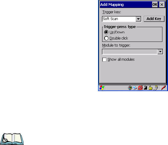
Chapter 5: Configuration
Manage Triggers
108 WORKABOUT PRO G2 Hand-Held With Windows Embedded CE 5.0 User Manual
OK
The OK button in the top right of the Manage Triggers screen saves all changes
made. If the cancel button X is tapped instead, or the [ESC] key is pressed, all
changes made will be discarded.
5.6.6.2 Add And Edit Trigger Mapping
These dialogs allow the user to add and edit trigger mappings.
Trigger Key
This dropdown list allows you to specify the source of the trigger events, such as the
Grip Trigger, Left Scan, etc., for the trigger module selected.
Notes: It is possible to map the same source to different modules (trigger con-
sumers)—for example, to both the Imager and Non-Decoded Scanner. If
so, both devices/operations will occur simultaneously. This is not recom-
mended in most cases, especially with devices such as Imagers or RFID
Readers.
It is also possible to map different sources to the same module (trigger
consumer)—for example, two different trigger keys can be mapped to the
RFID File System.
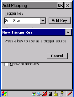
WORKABOUT PRO G2 Hand-Held With Windows Embedded CE 5.0 User Manual 109
Chapter 5: Configuration
Manage Triggers
Add Key
Only existing trigger sources are shown in the Source combo-box. To add a new
source to this list, tap on the Add Key button. A dialog will pop up and allow you to
select the keyboard key to use as a trigger source.
Trigger-Press Type
You can enable either an Up/Down or Double Click response to a trigger press.
Normally, when a trigger (keyboard key, etc.) is pressed and released, a “trigger
down” event is sent to the “owner”—that is, the application receiving the trigger
press information—followed by a “trigger up”. If Double Click is chosen in this
menu, when the trigger is pressed, released, and then pressed again, a “double-click”
event will have occurred. If a mapping with the type Up/down has also been
configured for the same source, it will only receive the first set of trigger events.
Module Trigger
This identifies the driver or application receiving the trigger presses.
Show All Modules
By default, inactive owners are not shown. By checking this checkbox, all owners,
both active and inactive, are displayed.
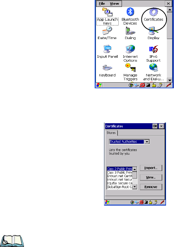
Chapter 5: Configuration
Certificate Assignment
110 WORKABOUT PRO G2 Hand-Held With Windows Embedded CE 5.0 User Manual
5.6.7 Certificate Assignment
•In the Control Panel, choose the Certificate icon.
Figure 5.7 Certificates Icon
This option is used in conjunction with 802.1x authentication to enhance
WORKABOUT PRO G2 security.
For a detailed description about Certificate setup for both the server and client-side
devices (WORKABOUT PRO G2s), refer to the following website:
http://www.microsoft.com/windowsserver2003/techinfo/overview/security.mspx
Note: When importing certificates, the WORKABOUT PRO G2 only recognizes
.cer files.
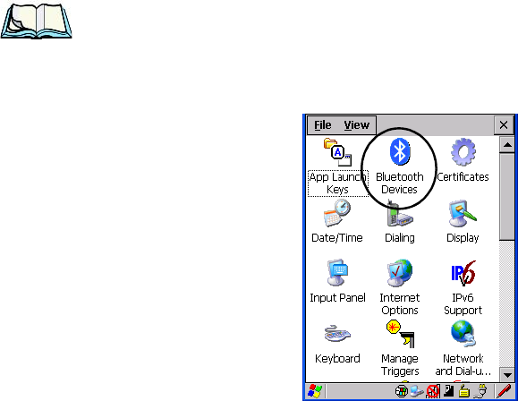
WORKABOUT PRO G2 Hand-Held With Windows Embedded CE 5.0 User Manual 111
Chapter 5: Configuration
Bluetooth Setup
5.7 Bluetooth Setup
Bluetooth is a global standard for wireless connectivity for digital devices and is
intended for Personal Area Networks (PAN). The technology is based on a
short-range radio link that operates in the ISM band at 2.4 GHz. When two
Bluetooth-equipped devices come within a 5 meter range of each other, they can
establish a connection. Because Bluetooth utilizes a radio-based link, it does not
require a line-of-sight connection in order to communicate.
Note: The Bluetooth radio uses an internal antenna.
•In the Control Panel, choose the Bluetooth Device Properties icon to
display the Bluetooth Control screen.
Figure 5.8 Bluetooth Icon
The Bluetooth Control dialog box is used to display the other Bluetooth devices with
which you can communicate.
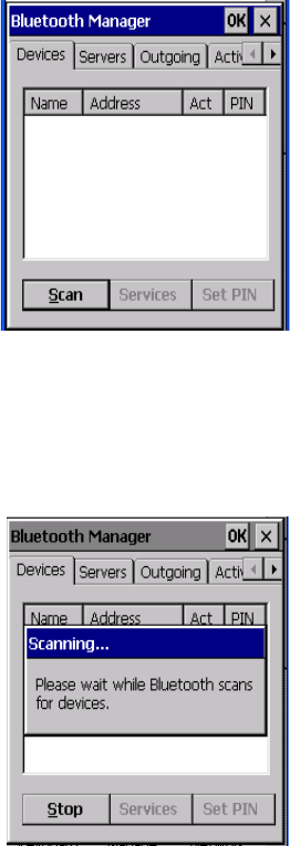
Chapter 5: Configuration
The Devices Tab
112 WORKABOUT PRO G2 Hand-Held With Windows Embedded CE 5.0 User Manual
5.7.1 The Devices Tab
If you intend to configure Bluetooth communication with specific devices (a
scanner or printer for example), power on and bring the devices within 5 m (16.4 ft.)
of the hand-held before proceeding with the discovery process described below.
Scan•Click on the Scan button to list available devices.
Figure 5.9 Available Bluetooth Devices
Wait for the WORKABOUT PRO G2 to complete its scan (approximately 20
seconds). When scanning starts, the Scan button will change to Stop—if necessary,
you can tap on this button to stop the process. Once scanning is complete, all
discovered devices will be displayed in the list box, with Name, Address, Active
status, and PIN information.

WORKABOUT PRO G2 Hand-Held With Windows Embedded CE 5.0 User Manual 113
Chapter 5: Configuration
The Devices Tab
Note: During the scanning process, addresses are located first, followed by
names. Only the names of devices that are within the Bluetooth radio cov-
erage range will be retrieved.
The Active column indicates whether any service is activated for that device. When
a service is activated, the device is displayed in the list even when it is not detected
during the scan.
The PIN column indicates whether you have a PIN (password) set for the device.
At this point you can either query for services or set the PIN for each device. Once
you highlight a device in the list box, both the Services and Set PIN buttons
become available.
Services
A discovered device may display several service profiles that it can use to
communicate, and you will want to activate the type you need. Supported profiles
that can be activated include: DUN (Dial-Up Networking service), Printer (serial
service), and LANPPP (LANAccessUsingPPP service). ASync (ActiveSync) is
another available profile.
• To start the service scan, highlight a device in the Devices tab list, and then
click on the Services button or double-click on the device entry.
Note: If the remote device is out of reach or turned off, it can take a consider-
able amount of time for the Services dialog box to appear—it may appear
to be frozen.
Once the device’s service profiles are displayed in the Services list box:
• Highlight the service to be activated.
• Press [SPACE] or right-click to display the Activation menu.
The Activation menu contains four options: Activate, Authenticate, Outgoing,
and Encrypt.
Once the service is successfully activated, the assigned port (if applicable) will
appear in the Port column of the Services list box. You can choose to use BSP or
COM as the port name. BSP is the latest Microsoft Bluetooth stack standard, but
older applications assume serial ports are COM. When using COM as the port name,
the Bluetooth manager will try to find and use a free port between COM7 and
COM9. When using BSP as the port name, BSP2 to BSP9 are available for use. The
port is available as soon as it is activated.

Chapter 5: Configuration
The Devices Tab
114 WORKABOUT PRO G2 Hand-Held With Windows Embedded CE 5.0 User Manual
Note: The CH column shows the RFCOMM channel of the service if the
service is RFCOMM-based. This information is not generally needed
except for debugging purposes.
To add a service to the Outgoing port, an active service must first be deactivated.
Then you can choose the ‘Outgoing’ option from the Activation menu (highlight a
service, right-click or press the [SPACE] bar to display the Activation menu).
The Authentication and Encryption options can be changed only before activation.
To change these after activation, deactivate the service first, then change the options.
Once a service is activated, all the information regarding the service, including the
RFCOMM channel number, is saved in the registry. (Some remote devices may
change their RFCOMM channel numbers when they reboot, so your saved setting
may not work when the remote device is rebooted. In that case, you must deactivate
the service and reactivate it to detect the current RFCOMM channel.)
Set PIN
PINs can be set for each device by pressing the Set PIN button in the Devices tab, or
you can skip this step and try to connect to the device first.
Important: The remote device must have authentication enabled, otherwise the
PIN authentication will fail.
• Highlight a device, click on the Set Pin button, and type the PIN.
You will receive a message, either that the PIN has been successfully validated or
that it has been rejected.
If the PIN has been validated, an asterisk (*) appears in the PIN column in the
Devices list box, indicating that this device has a PIN set. Once a PIN is entered, it is
saved in the registry.
To remove the PIN:
• Choose Set PIN, and press [ENTER].
If the WORKABOUT PRO G2 attempts to connect to a remote device that has
Authentication enabled and does not have a required PIN set, an Authentication
Request dialog
box appears.
• Enter the PIN, and tap on OK to connect the devices.
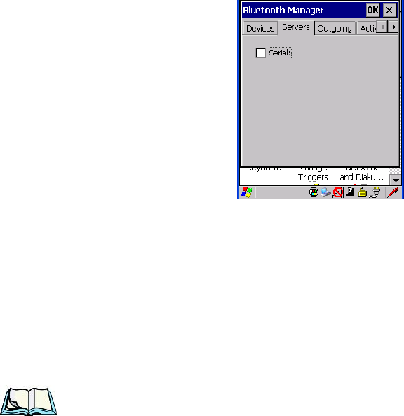
WORKABOUT PRO G2 Hand-Held With Windows Embedded CE 5.0 User Manual 115
Chapter 5: Configuration
The Servers Tab
5.7.2 The Servers Tab
The Bluetooth connection is initiated from your WORKABOUT PRO G2 to the
remote device. Therefore the WORKABOUT PRO G2 is called the ‘client’ and the
remote is called the ‘server’. The Servers tab displays the server profiles that can be
activated in your WORKABOUT PRO G2. There is currently one server profile
available: Serial.
• Tap on the checkbox to activate the server, and it will display the
associated port name beside the server name.
Once you activate a server profile, it is recommended that the WORKABOUT PRO
G2 be rebooted before you try to bond from a server.
Note: You do not need to reboot if you are deactivating a server.
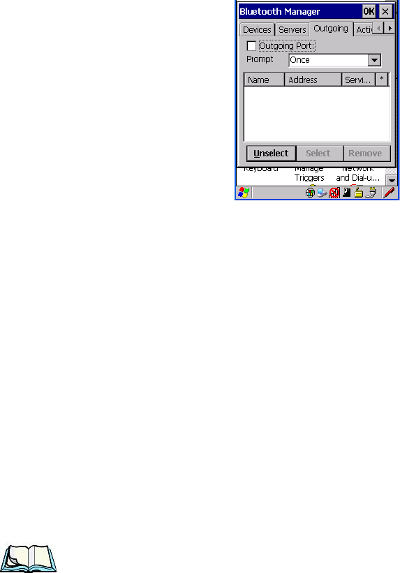
Chapter 5: Configuration
Outgoing Tab
116 WORKABOUT PRO G2 Hand-Held With Windows Embedded CE 5.0 User Manual
5.7.3 Outgoing Tab
Outgoing Port acts as a serial port that can be used to connect to a list of Bluetooth
devices (one at a time), but you have the freedom to switch on-the-fly.
The Outgoing Port checkbox allows you to create the Outgoing port. When the port is
created, the Outgoing tab lists the port name.
The Outgoing list dialog box displays a list of services marked as ‘Outgoing’. The *
column indicates the currently selected service. You can tap on Unselect to reset the
current selection, or you can tap on Select to make a selection. The Remove button
deletes the service from the outgoing list.
The Prompt menu determines the behaviour of the pop-up Selection menu.
Choosing Everytime causes the Selection menu to be displayed each time an
outgoing port is created. If you choose Once, the menu is displayed only when a
partner service is not selected.
To display the Selection menu at any time:
• Press [CTRL] [ALT] [F1], and switch the partner Bluetooth device.
If a connection to a partner device already exists, the connection is dropped and
another connection to the newly selected device is created instantly without
disrupting the application that has opened the outgoing port.
Note: To add a service to the Outgoing port, an active service must first be
deactivated. Then you can choose the ‘Outgoing’ option from the Activa-
tion menu (highlight a service, right-click or press the [SPACE] bar to
display the Activation menu).
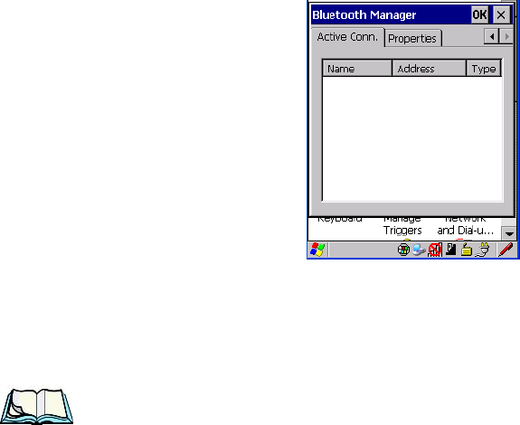
WORKABOUT PRO G2 Hand-Held With Windows Embedded CE 5.0 User Manual 117
Chapter 5: Configuration
Active Conn. Tab
5.7.4 Active Conn. Tab
The Active Conn. tab lists the Name, Address, and Type of the currently active
connections. The table is periodically updated, but it can take a few seconds before
it reflects the actual list of connections. The Type column of the table shows ‘ACL’
or ‘SCO’. The Connection list table shows the connections for scanning as well as
the service connections.
Note: You can change the device-name and description of your radio by clicking
on the System icon in Control Panel, which will open the System Proper-
ties dialog box. Click on the Device Name tab to access the menu and
change your settings. Then click on OK.
Although the name will have changed in the Properties menu in Bluetooth
Controls, the radio only reads it on boot-up. For the changes to take
effect, you must cold reset the WORKABOUT PRO G2 (for cold reset
instructions, see “Resetting The Hand-Held” on page 31).
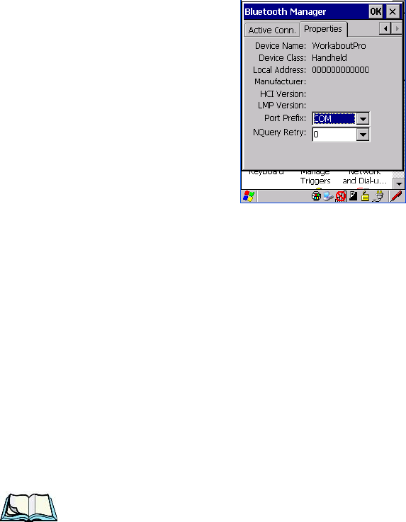
Chapter 5: Configuration
The Properties Tab
118 WORKABOUT PRO G2 Hand-Held With Windows Embedded CE 5.0 User Manual
5.7.5 The Properties Tab
The Properties tab displays information about your WORKABOUT PRO G2, and
provides some port options.
The Device Name field shows the device name of your WORKABOUT PRO G2.
This name can be changed (see the Note on the previous page for details).
Device Class shows the Class of Device (e.g. desktop, hand-held), which is always
set to Handheld.
Local Bluetooth Address shows the address of your WORKABOUT PRO G2 radio.
Port Prefix is used to set the port name to either BSP or COM. When the name is set
to BSP, BSP2 to BSP9 are available for activated services (including the server).
When COM is chosen, COM7 to COM9 are available.
NQuery Retry (Name Query Retry) governs the number of times the hand-held will
attempt to query the names of other Bluetooth devices if the first attempt fails.
(When the WORKABOUT PRO G2 scans for other devices, it sometimes fails to
scan names.)
Note: Keep in mind that setting this parameter to a higher value will lengthen
the scan time.
5.7.6 The Bluetooth GPRS WAN Connection
The following steps describe how to set up an internet data connection using a GSM
cellular telephone with Bluetooth. The WORKABOUT PRO G2 communicates via
Bluetooth to the cell phone, which then accesses a WAN (Wide Area Network) and
transfers data using GPRS.
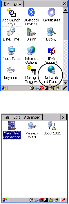
WORKABOUT PRO G2 Hand-Held With Windows Embedded CE 5.0 User Manual 119
Chapter 5: Configuration
The Bluetooth GPRS WAN Connection
1. To set up the internet parameters, choose the Network And Dial-up
Connections icon from the Control Panel.
Figure 5.10 Network And Dial-up Connection Icon
2. Choose the Make New Connection icon.
Figure 5.11 Creating A GPRS Connection
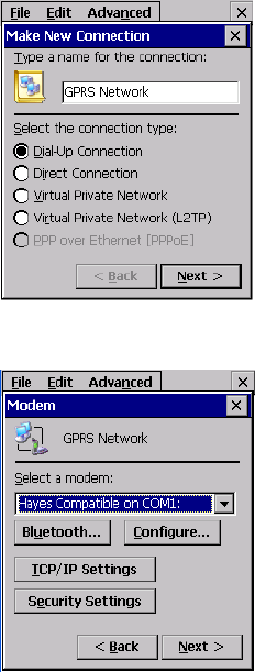
Chapter 5: Configuration
The Bluetooth GPRS WAN Connection
120 WORKABOUT PRO G2 Hand-Held With Windows Embedded CE 5.0 User Manual
3. In the Make New Connection dialog box, choose Dial-Up Connection.
Enter a name for your GPRS network connection.
4. Choose the Next button to display the Modem dialog box.
5. In the drop-down menu labelled Select a modem, choose the name
of the modem with which you want to connect, and then choose the
Configure button to display the Device Properties dialog box.
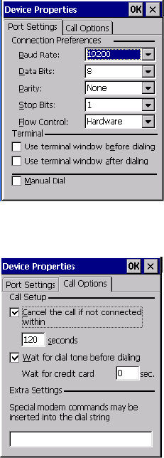
WORKABOUT PRO G2 Hand-Held With Windows Embedded CE 5.0 User Manual 121
Chapter 5: Configuration
The Bluetooth GPRS WAN Connection
The WORKABOUT PRO G2 communicates via Bluetooth to your Blue-
tooth-equipped cellular telephone and retrieves the parameters for the
Device Properties dialog box. The WORKABOUT PRO G2 then discon-
nects.
6. Under the Call Options tab, turn off Cancel the call if not connected
within, and press [ENTER] to save your changes.
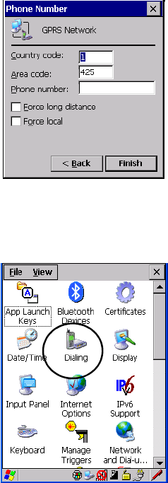
Chapter 5: Configuration
The Bluetooth GPRS WAN Connection
122 WORKABOUT PRO G2 Hand-Held With Windows Embedded CE 5.0 User Manual
7. In the Modem dialog box, choose the Next button to display the Phone
Number dialog box.
The phone number you enter is network carrier dependent. Once you’ve
specified all the necessary information, choose the Finish button.
8. In the Control Panel, choose the Dialing icon.
9. The values in the Dialing Properties dialog box need to be edited
according to your network carrier specifications.
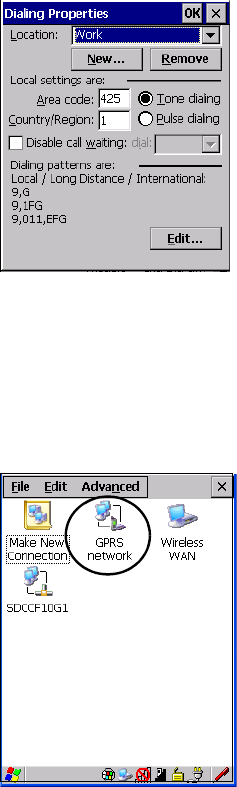
WORKABOUT PRO G2 Hand-Held With Windows Embedded CE 5.0 User Manual 123
Chapter 5: Configuration
The Bluetooth GPRS WAN Connection
Once you’ve edited this dialog box to reflect your network carrier require-
ments, press [ENTER] to save your changes.
10. At this point, you’ll need to return to the Control Panel, and choose the
Network and Dial-up Connections icon.
11. In the network connection window, the new network configuration, in
this case GPRS Network is displayed. Tap on the new icon.
When you tap on your new connection, an onscreen message indicates the
status of your connection: connected, disconnected, error messages, and so
on.
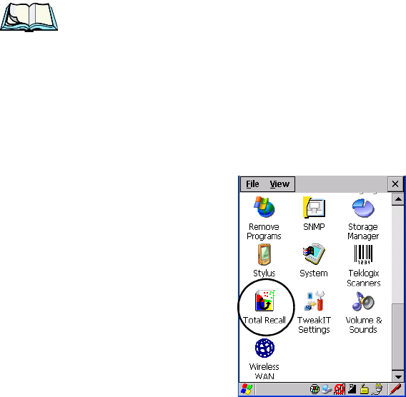
Chapter 5: Configuration
Total Recall
124 WORKABOUT PRO G2 Hand-Held With Windows Embedded CE 5.0 User Manual
5.8 Total Recall
Total Recall is a Psion Teklogix utility developed to back up/restore applications and
settings. Keep in mind that to protect your data from erasure during a ‘clean start’,
the Total Recall profile must be stored on a SD/MMC card or externally to the
device on a USB memory stick or on a PC.
Note: In Windows Embedded CE 5.0, the registry and installed programs are
stored in the Flash file system and are not lost on reset. However, a clean
start will reset not only the registry settings to factory defaults, but will
also erase any files or applications stored or installed on the built-in
Flash file system, including any Total Recall profiles. This is why any data
that needs to be protected must be stored on a SD/MMC card or exter-
nally to the device on a USB memory stick or on a PC.
•In the Control Panel, choose the Total Recall icon
Figure 5.12 Total Recall Icon
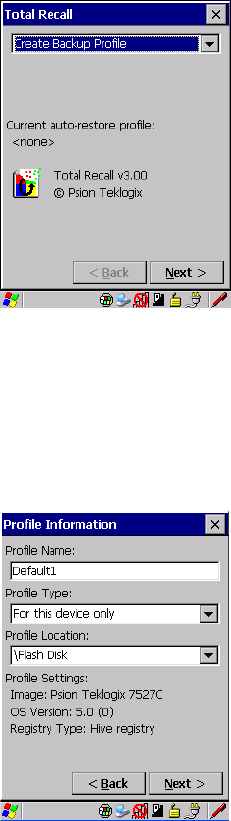
WORKABOUT PRO G2 Hand-Held With Windows Embedded CE 5.0 User Manual 125
Chapter 5: Configuration
Creating A Backup Profile
5.8.1 Creating A Backup Profile
In the drop-down menu, you can choose from four options: Create Backup Profile,
View Selected Profile, Restore Selected Profile and Delete Selected Profile. Keep in
mind however that until a profile is created, the only available option is Create
Backup Profile.
• Choose the Next button to begin the process.
Profile Information
This dialog box lists the possible storage destinations for the profile file.
• To begin, type a name for the profile in the field labelled Profile Name.
• Next, choose the Profile Type you want to create:
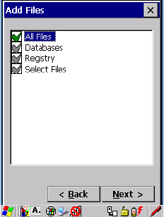
Chapter 5: Configuration
Creating A Backup Profile
126 WORKABOUT PRO G2 Hand-Held With Windows Embedded CE 5.0 User Manual
•For this device only–creates a backup that is manually restored by the opera-
tor.
•AutoRestore for this device only–creates a profile that automatically restores
itself following a clean start.
•AutoRestore for this and other devices–creates a profile that automatically
restores after resuming from a clean start, but it will not contain the
touchscreen calibration coordinates or the Wireless radio settings.
•Finally, choose a Profile Location – The location for the profile is either
\Flash Disk or \SD-MMC Card.
• Tap on the Next button to display the next dialog box Add Files.
Add Files
Figure 5.13 Adding Files
By default, All Files is selected so that all installed or copied files, database entries,
and the Registry will be saved. You can, however, limit the backup to databases,
and/or the registry only. By tapping the checkbox next to these items, you can add or
remove a check mark to enable or disable the option.
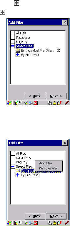
WORKABOUT PRO G2 Hand-Held With Windows Embedded CE 5.0 User Manual 127
Chapter 5: Configuration
Creating A Backup Profile
The Select Files option allows you to select predefined file types.
• Remove the check mark next to All Files. You’ll notice the checkbox next
to Select Files changes , indicating that additional options are available.
• Choose this icon next to Select Files to view your options.
Figure 5.14 By File Type
Choosing By Individual File displays a pop-up menu where you can tailor the list of
files you want to back up.
Figure 5.15 Add Files
To add a file to your backup list:
• Choose Add Files. Browse to and choose the files you want to add to
your list.
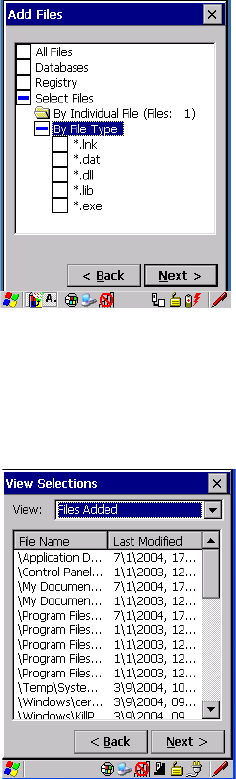
Chapter 5: Configuration
Creating A Backup Profile
128 WORKABOUT PRO G2 Hand-Held With Windows Embedded CE 5.0 User Manual
To remove a file from your backup list:
• Choose Remove Files—a dialog box is displayed listing the files that will
be backed up.
• Highlight the item you want to remove from the list, and tap on the
Remove button.
Choosing By File Type allows you to select the file types that you want backed up.
Figure 5.16 Adding Files By File Type
View Selections
Depending on what you have selected for inclusion in your profile, you can view a
list of the selected files, databases and/or registry.
• Choose the Next button to perform the operation.
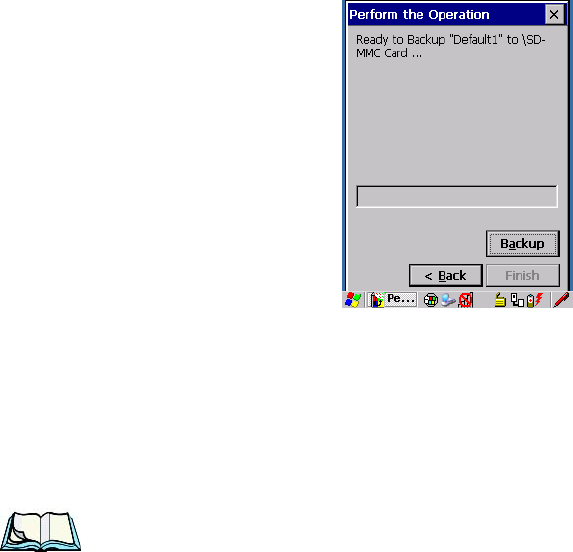
WORKABOUT PRO G2 Hand-Held With Windows Embedded CE 5.0 User Manual 129
Chapter 5: Configuration
Restoring A Profile
Perform The Operation
Figure 5.17 Performing The Backup
• Choose the Backup button to start the process, and create a profile.
5.8.2 Restoring A Profile
To manually restore a profile:
• Choose Restore Selected Profile from the drop-down menu, and choose
the Profile Name displayed in the drop-down menu.
Note: You can also manually restore an auto restore profile located in flash or a
storage device.
5.9 The Storage Manager
The Storage Manager allows the user to view information about the storage devices
that are present in the WORKABOUT PRO G2, such as SD-MMC flash cards and
Compact Flash cards.
5.9.1 Formatting A Memory Card
Formatting a memory card bulk-erases it. Once a card is erased, partitions may be
created in it, similarly to those on a hard drive. Memory-card devices are normally
‘mounted’ (made available to the system) automatically when they are inserted.
They must be dismounted before they can be formatted.
To format an entire memory card:
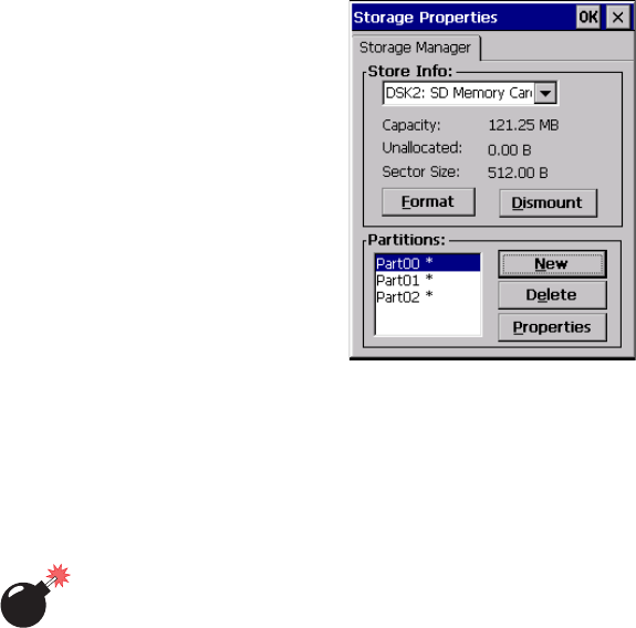
Chapter 5: Configuration
Creating Partitions
130 WORKABOUT PRO G2 Hand-Held With Windows Embedded CE 5.0 User Manual
1. Select Start> Settings>Control Panel.
2. In Control Panel, double-click on the Storage Manager icon.
The Storage Manager menu opens:
3. Select the memory card from the drop-down list.
4. Press the Dismount button to dismount the memory card. All partitions
on the card will be dismounted.
5. Press the Format button to format the memory card.
Warning: All partitions and information on the card will be erased during the
formatting process.
5.9.2 Creating Partitions
Once the card is formatted, new partitions can be created in it. The default is to
create one partition that occupies the whole card, but a card can be divided into
more than one partition if desired. Each partition appears as a separate folder in
Windows Explorer.
To create new partitions:
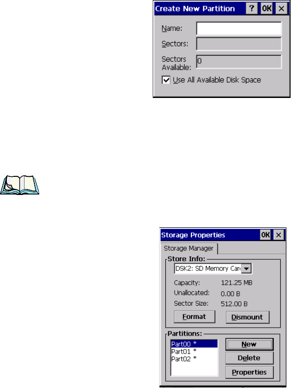
WORKABOUT PRO G2 Hand-Held With Windows Embedded CE 5.0 User Manual 131
Chapter 5: Configuration
Creating Partitions
1. Press the New button next to the Partitions list box. The New Partition
dialog appears:
2. Enter a name for the partition.
3. If more than one partition is desired, uncheck the Use All Available
Disk Space checkbox, then specify the desired number of sectors to be
used by the partition:
Note: The sector size of the card is given on the left-hand side of the Storage
Properties dialog.
4. Press OK. The new partition appears in the Partitions list:
The new partition is automatically mounted. This is indicated by an asterisk (*) next
to its name in the partition list. Any unallocated space on the card is indicated at the
left, and additional partitions can be created in it.
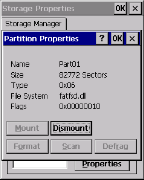
Chapter 5: Configuration
Partition Management
132 WORKABOUT PRO G2 Hand-Held With Windows Embedded CE 5.0 User Manual
5.9.3 Partition Management
Partitions can be individually dismounted, mounted, deleted, or formatted as well.
These and additional tasks are available from the Partition Properties dialog:
To dismount a partition:
1. Select the desired partition.
2. Press the Properties button. The Partition Properties dialog appears.
3. Press the Dismount button. The partition is dismounted. The asterisk
disappears next to its name in the partitions list.
To delete a partition:
1. Select the desired partition.
2. Press the Delete button. A warning dialog appears.
3. Press the OK button. The partition is deleted.
To format a partition:
1. Select the desired partition.
2. Press the Properties button. The Partition Properties dialog appears.
3. Press the Dismount button. The partition is dismounted. The asterisk
disappears next to its name in the partitions list.
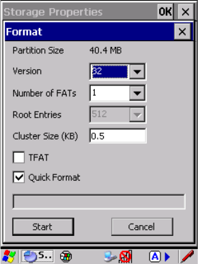
WORKABOUT PRO G2 Hand-Held With Windows Embedded CE 5.0 User Manual 133
Chapter 5: Configuration
Partition Management
4. Press the Format button. The Format dialog appears:
5. Choose your format options. These options include:
• Version of file system (FAT-16, for devices holding up to 4 GB; or
FAT-32, for devices containing up to 32 GB).
• Number of FATs (File-Allocation Tables).
• Number of entries allowed in the root directory.
• Cluster size (.5 KB to 64 KB).
There are also two checkboxes, which govern:
• Whether to use the transaction-safe FAT file system (TFAT). This file
system keeps multiple copies of the file-allocation table, changing one
while maintaining another as a backup.
• Whether to perform a quick format. Quick formatting removes all ref-
erence to data in the partition without erasing the actual partition. The
partition will be treated as empty, and new data will overwrite it.
6. Press Start. The partition is formatted.
To mount a partition:
1. Select the desired partition.
2. Press the Properties button. The Partition Properties dialog appears.
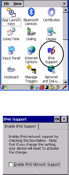
Chapter 5: Configuration
IPv6 Support
134 WORKABOUT PRO G2 Hand-Held With Windows Embedded CE 5.0 User Manual
3. Press the Mount button. The partition is mounted. The asterisk appears
next to its name in the partitions list.
The Partition Properties dialog has buttons for additional functions. Partitions can be
defragmented, and their file structure can be scanned.
5.10 IPv6 Support
The IPv6 Support icon in the Control Panel allows you to activate IPv6 network
support on your unit if your network setup requires this. This internet protocol
specification (version 6) supports 128-bit IP addresses, replacing version 4.
Figure 5.18 IPv6 Support Icon
• Choose the IPv6 Support icon to display the associated dialog box.
• Choose the checkbox next to Enable IPv6 Network Support to enable this
internet protocol.
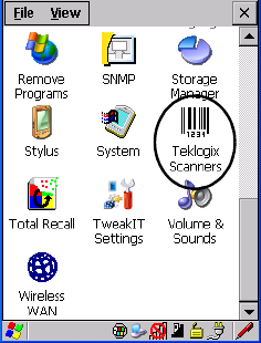
WORKABOUT PRO G2 Hand-Held With Windows Embedded CE 5.0 User Manual 135
Chapter 5: Configuration
Scanner Settings
5.11 Scanner Settings
The Teklogix Scanners icon in the Control Panel provides dialog boxes in which
you can tailor bar code options and choose the bar codes your scanner will
recognize. The parameters are preset with the default settings of the decoded
scanner installed in the unit.
If you wish to recover the factory defaults after making changes, the defaults can be
applied to a selected parameter, sub-tree of parameters, or all scanner parameters.
Using the stylus, holding on a symbology will pop up a menu to default the sub-tree,
or all settings. Holding on an individual setting will pop up a menu to default that
setting, or all settings. This option cannot be accessed without a touchscreen.
For a listing of available scanners and their specifications, please refer to Chapter 7:
“Specifications”.
Figure 5.19 Teklogix Scanners Icon
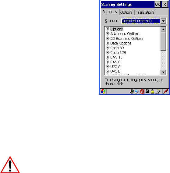
Chapter 5: Configuration
Bar Codes
136 WORKABOUT PRO G2 Hand-Held With Windows Embedded CE 5.0 User Manual
5.11.1 Bar Codes
5.11.1.1 Scanner
The dropdown menu to the right of the Scanner option allows you to choose from
one of the following scanner types used with your hand-held: Decoded (internal),
Decoded (HHP), Decoded (Intermec ISCP) and Imager.
The symbologies listed change to reflect the scanner you choose and the bar codes it
supports.
Important: To improve the decode speed and performance, enable only those
codes that are required by the application.
Keep in mind that some bar code types are only available when an internal imaging
scanner is installed. All internal scanners can be configured using the Barcode
dialog boxes.
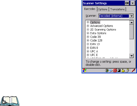
WORKABOUT PRO G2 Hand-Held With Windows Embedded CE 5.0 User Manual 137
Chapter 5: Configuration
Decoded (Internal) Scanners
5.11.2 Decoded (Internal) Scanners
• Tap on the Scanner drop-down menu, and choose Decoded (internal).
5.11.2.1 Options
Note: Some options are available only for specific scanners. Refer to the option
names in this section for scanner model identification.
Dot Time (msec)
The value selected for “Dot Time (msec)” determines (in milliseconds) how long
the targeting dot remains on before the scanner switches to a normal scan sweep.
When you double-tap on this parameter, a dialog box is displayed in which you can
enter a value of 0 msec, 200 msec or 400 msec. A value of 0 (zero) disables the
target dot.
Aim Duration
This parameter determines the total time the aiming pattern appears before the
scanner laser begins sweeping. When you double-tap on this parameter, a dialog box
is displayed in which you can enter a value from 0 to 30 (0 to 3 sec.). A value of 0
(zero) disables the aiming-dot.
Chapter 5: Configuration
Decoded (Internal) Scanners
138 WORKABOUT PRO G2 Hand-Held With Windows Embedded CE 5.0 User Manual
Laser On Time
The value assigned to this parameter determines how long the laser will remain on
when the scan button or trigger is pressed.Double-tapping on this parameter
displays a dialog box in which you can enter a value between 5 and 99, each
number representing 0.1 seconds.
5.11.2.2 Decoded (Internal) Advanced Options
Continuous Scan Mode
Setting this parameter to ‘on’ keeps the laser on and continuously decoding as long
as the scanner button is pressed and held down.
Minimum Cancel Time
The value assigned to this parameter determines the time delay before the scanner is
turned off, once the scanner trigger or button is released. This gives the scanner a
minimum amount of time to complete its current decode before the scan is cancelled
when the user quickly triggers on/off.
Low Power Timeout
To extend laser life, you can select the time the scanner remains active following a
successful decode. The scanner wakes from low power mode when a bar code is
scanned—a successful decode restores normal blinking.
This is only used if the unit’s Trigger Mode has been changed to Continuous On. If
the unit is used in a fixed mount this parameter might be used, but not if the unit is
used as a hand-held.
When you double-tap on this parameter, a dialog box is displayed in which you can
choose a value of 30 sec., 1 min., 2 min. or 3 min.
Parameter Scanning
Setting this parameter to ON enables decoding of parameter bar codes.
Linear Security Level
This parameter allows you to select the security level appropriate for your bar code
quality. There are four levels of decode security for linear code types (e.g., Code 39,
Interleaved 2 of 5). Higher security levels should be selected for decreasing levels of
bar code quality. As security levels increase, the scanner’s decode speed decreases.
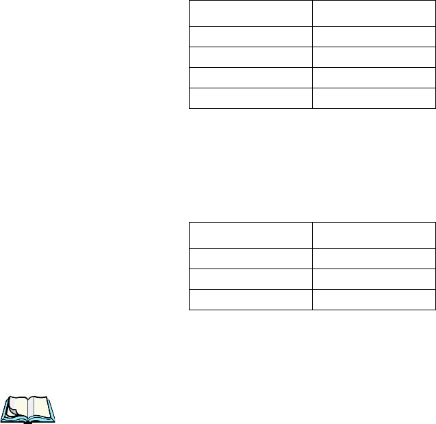
WORKABOUT PRO G2 Hand-Held With Windows Embedded CE 5.0 User Manual 139
Chapter 5: Configuration
Decoded (Internal) Scanners
Double-tapping on this parameter displays a dialog box in which you can enter a
value from 1 to 4.
Linear security level 1 specifies that the following code types must be successfully
read twice before being decoded:
“Linear security level 2” specifies that all types of codes must be successfully read
twice before being decoded.
“Linear security level 3” specifies that code types other than the following must be
successfully read twice before being decoded. The following codes must be read
three times:
“Linear security level 4” requires that all code types be successfully read three times
before being decoded.
Bi-Direction Redundancy
Note: This parameter is only valid if a” Linear Security Level” is enabled.
When this parameter is enabled, a bar code must be successfully scanned in both
directions (forward and reverse) before being decoded.
5.11.2.3 Decoded (Internal) 2D Scanning Options
Scanning Mode
When you double-tap on this parameter, a dialog box is displayed in which you can
choose one of the following scanning modes: Smart Raster, Always Raster,
Programmable Raster, Slab Pattern, Cyclone Pattern or Semi-Omni Pattern.
Code Type Length
Codabar All
MSI Plessey 4 or less
D 5 of 5 8 or less
I 2 of 5 8 or less
Code Type Length
MSI Plessey 4 or less
D 2 of 5 8 or less
I 2 of 5 8 or less

Chapter 5: Configuration
Decoded (Internal) Scanners
140 WORKABOUT PRO G2 Hand-Held With Windows Embedded CE 5.0 User Manual
Raster Height And Raster Expand Rate
These parameter determine the laser pattern’s height and rate of expansion.
Note: These parameters are only used when either Programmable Raster or
Always Raster is assigned to the “2D Scanning Mode” parameter.
“2D Raster Height” and “2D Raster Expand Rate” are intended for very
specific applications and are usually not required for normal scanning
purposes.
Double-tapping on this parameter displays a dialog box in which you can enter a
value from 1 to 15.
5.11.2.4 Decoded (Internal) 2D Scanning Options
Transmit Code ID Char
A code ID character identifies the scanned bar code type. In addition to any single
character prefix already selected, the code ID character is inserted between the
prefix and the decoded symbol.
When you double-tap on this parameter, a dialog box is displayed in which you can
choose a transmit code: None, AIM or Symbol.
Scan Data Format
This parameter allows you to change the scan data transmission format.
Double-tapping on “Scan Data Format” displays the following options from which
you can choose a data format: data (as-is), data [S1], data [S2], data [S1][S2],
[P] data, [P] data [S1], [P] data [S2] and [P] data [S1][S2].
Prefix [P], Suffix [S1] And Suffix [S2]
A prefix and/or one or two suffixes may be appended to scan data for use in data
editing.
When you double-tap on these parameters, a dialog box is displayed in which you
can enter a value from 0 to 255.
Delete Char Set ECIs
Setting this parameter to on enables the scanner to delete any escape sequences
representing Character Set ECIs – Extended Channel Interpretations (also known as
GLIs) from its buffer before transmission.

WORKABOUT PRO G2 Hand-Held With Windows Embedded CE 5.0 User Manual 141
Chapter 5: Configuration
Decoded (Internal) Scanners
When this parameter is enabled, the scanner transmits data from PDF417 and
MicroPDF417 bar codes containing Character Set ECIs, even when the ECI
Protocol is disabled.
ECI Decoder
Setting this parameter to on enables the scanner to interpret any Extended Channel
Interpretations (ECIs) supported by the scanner. This parameter has no effect on
symbols that were not encoded using ECIs.
If this parameter is set to off and a symbol that was encoded using an ECI escape is
scanned, the scanner transmits the ECI escape followed by the data that was not
interpreted.
5.11.2.5 Code 39
Enabled
Setting this parameter to on enables “Code 39”.
Enable Trioptic Code 39
Note: “Trioptic Code 39” and “Full ASCII” should not be enabled simulta-
neously. The scanner does not automatically discriminate between these
two symbologies.
Trioptic Code 39 symbols always contain six characters. Setting this parameter to
on allows this type of symbology to be recognized.
Convert To Code 32
Note: “Code 39” must be enabled in order for this parameter to function.
Setting this parameter to on allows the scanner to convert the bar code from “Code
39” to “Code 32”.
Code 32 Prefix
Note: “Convert to Code 32” must be enabled in order for this parameter to
function.
When this parameter is enabled, the prefix character “A” is added to all “Code 32”
bar codes.
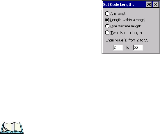
Chapter 5: Configuration
Decoded (Internal) Scanners
142 WORKABOUT PRO G2 Hand-Held With Windows Embedded CE 5.0 User Manual
Set Length L1 And Set Length L2
Lengths for “Code 39” can be set for Any length, Length within a range, One
discrete length or Two discrete lengths. The length of a code refers to the number of
characters (i.e., human readable characters), including check digit(s).
Double-tapping on this parameter displays a dialog box labelled Set Code Lengths
where you can define the code length that will be decoded by your scanner
Choosing One discrete length allows you to decode only those codes containing a
selected length. Choosing Two discrete lengths allows you to decode only those
codes containing two selected lengths. Length within a range allows you to decode
a code type within a specified range from 1 to 55.
Check Digit Verification
When this parameter is enabled (set to on), the integrity of a “Code 39” symbol is
checked to ensure that it complies with specified algorithms.
Note: Only those “Code 39” symbols that include a Mod 43 check digit are
decoded when this parameter is enabled.
Transmit Check Digit
If the check digit is to be transmitted with the data, this parameter must to enabled.
Full ASCII
If this parameter is enabled, the characters +, %, and / are used as escape characters.
The combination of an escape character and the next character is converted to an
equivalent ASCII character.
Decode Performance
If this parameter is enabled, one of three decode levels can be chosen in the “Decode
Performance Level” parameter.

WORKABOUT PRO G2 Hand-Held With Windows Embedded CE 5.0 User Manual 143
Chapter 5: Configuration
Decoded (Internal) Scanners
Decode Perf. Level
This parameter provides three levels of decode performance or “aggressiveness” for
Code 39 symbols. Increasing the performance level reduces the amount of required
bar code orientation – this is useful when scanning very long and/or truncated bar
codes. Keep in mind that increased levels reduce decode security.
When you double-tap on this parameter, a dialog box is displayed in which you can
enter a decode performance level of between 1 and 3.
Field Size/Chars
Field Size
The field size is the length of the field after the first character is stripped and the
prefix and suffix characters are added. If the field size is non-zero, only bar codes of
that length are passed through.
Prefix Char
This character, if non-zero, is added before a successfully decoded bar code. Press
the key you want to insert in the dialog box attached to this parameter. The
ASCII/Unicode key value of the keypress is displayed.
Suffix Char
This character, if non-zero, is added after a successfully decoded bar code. Press the
key you want to insert in the dialog box attached to this parameter. The
ASCII/Unicode key value of the keypress is displayed.
Strip Leading
This parameter determines the number of characters that will be removed from the
beginning of the bar code before the prefix character is added.
Note: For Code 39 bar codes, the “AIAG Strip” is performed before the
“Strip Leading”.
Strip Trailing
The value entered in this parameter determines the number of characters that will be
removed from the end of the bar code before the suffix character is added.
Chapter 5: Configuration
Decoded (Internal) Scanners
144 WORKABOUT PRO G2 Hand-Held With Windows Embedded CE 5.0 User Manual
5.11.2.6 Code 128
Enabled
Set this parameter to on to enable “Code 128”.
Enable GS1-128/GS1 US
Previously UPC/EAN and UCC, these types of bar codes include group separators
and start codes.
Enable ISBT 128
To successfully scan this variation, “Enable ISBT 128” must be set to on.
Decode Performance
If this parameter is set to on, one of three decode levels assigned to the “Decode
Performance Level” parameter can be selected.
Decode Perf. Level
This parameter provides three levels of decode performance or “aggressiveness” for
Code 128 symbols. Increasing the performance level reduces the amount of required
bar code orientation – this is useful when scanning very long and/or truncated bar
codes. Keep in mind that increased levels reduce decode security.
When you double-tap on this parameter, a dialog box is displayed in which you can
enter a decode performance level of between 1 and 3.
Field Size/Chars
Refer to page 143 for details.
5.11.2.7 EAN 13
Enabled
Set this parameter to on to enable “EAN 13”.
Prefix/Suffix
Prefix Char
This character, if non-zero, is added before a successfully decoded bar code. Press
the key you want to insert in the dialog box attached to this parameter. The
ASCII/Unicode key value of the keypress is displayed.

WORKABOUT PRO G2 Hand-Held With Windows Embedded CE 5.0 User Manual 145
Chapter 5: Configuration
Decoded (Internal) Scanners
Suffix Char
This character, if non-zero, is added after a successfully decoded bar code. Press the
key you want to insert in the dialog box attached to this parameter. The
ASCII/Unicode key value of the keypress is displayed.
Strip Leading
This parameter determines the number of characters that will be removed from the
beginning of the bar code before the prefix character is added.
Note: The appended character is treated as any other keyboard character.
For example, if [BKSP] is pressed, the usual action for that key
is performed.
Strip Trailing
The value entered in this parameter determines the number of characters that will be
removed from the end of the bar code before the suffix character is added.
5.11.2.8 EAN 8
Enabled
Set this parameter to ON to enable “EAN 8”.
EAN-8 Zero Extend
When this parameter is enabled, five leading zeros are added to decoded EAN-8
symbols, making them compatible in format to EAN-13 symbols. Disabling this
parameter returns EAN-8 symbols to their normal format.
Prefix/Suffix
See “Prefix/Suffix” beginning on page 144.
5.11.2.9 UPC A
Enabled
Set this parameter to ON to enable “UPC A”.
UPC-A, Check Digit
If you enable this parameter, the check digit is included with the decoded bar
code data.
Chapter 5: Configuration
Decoded (Internal) Scanners
146 WORKABOUT PRO G2 Hand-Held With Windows Embedded CE 5.0 User Manual
UPC-A, Preamble
When you double-tap on this parameter, a dialog box is displayed where you can
choose one of three options for lead-in characters for UPC-A symbols transmitted to
the host device:
System Char – system character transmitted with the data,
Country Code and System Char – both the country code (“0” for USA) and system
character are transmitted with the data, or
None – no preamble is transmitted. The lead-in characters are considered part of the
symbol.
Prefix/Suffix
See “Prefix/Suffix” beginning on page 144.
5.11.2.10 UPC E
Enabled UPC-E
Set this parameter to ON to allow “UPC E” bar code scans.
Enabled UPC-E1
Set this parameter to ON to allow “UPC-E1” (zero suppressed) bar code scans.
UPC-E And UPC-E1 Check Digit
If you enable one or both of these parameters, a check digit is included with the
decoded bar code data.
UPC-E And UPC-E1 Preamble
When you double-tap on one of these parameters, a dialog box is displayed where
you can choose one of three options for lead-in characters for UPC-E and UPC-E1
symbols transmitted to the host device:
System Char – system character transmitted with the data,
Country code and System Char – both the country code (“0” for USA) and system
character are transmitted with the data, or
None – no preamble is transmitted. The lead-in characters are considered part of
the symbol.
WORKABOUT PRO G2 Hand-Held With Windows Embedded CE 5.0 User Manual 147
Chapter 5: Configuration
Decoded (Internal) Scanners
Conv. UPC-E To UPC-A
This parameter converts UPC-E (zero suppressed) decoded data to UPC-A format
before transmission. After conversion, data follows UPC-A format and is affected
by UPC-A programming selections (e.g., Preamble, Check Digit).
Conv. UPC-E1 To UPC-A
This parameter converts UPC-E1 (zero suppressed) decoded data to UPC-A format
before transmission. After conversion, data follows UPC-A format and is affected
by UPC-A programming selections (e.g., Preamble, Check Digit).
Prefix/Suffix
Refer to “Prefix/Suffix” beginning on page 144.
5.11.2.11 UPC/EAN Shared Settings
The parameters you set here are a shared across all available UPC and EAN
bar codes.
Enable Bookland EAN
Setting this parameter to ON allows your scanner to recognize Bookland EAN
bar codes.
Supplementals
'Supplementals” are additionally appended characters (2 or 5).
Double-tapping this parameter displays a list of options. If Ignore is chosen,
UPC/EAN is decoded and the supplemental characters are ignored. If Decode is
chosen, UPC/EAN symbols are decoded with supplementals. Autodiscriminate
works in conjunction with the Supp. Redundancy parameter.
Supp. Redundancy
With “Autodiscriminate” selected in the “Supplementals” parameter, “Supp.
Redundancy” adjusts the number of times a symbol without supplementals is
decoded before transmission.
When you double-tap on this parameter, a dialog is displayed in which you can enter
a value between 2 and 20. A value of 5 or above is recommended when
Autodiscriminate is selected and you are decoding a mix of UPC/EAN symbols
with and without supplementals.
Chapter 5: Configuration
Decoded (Internal) Scanners
148 WORKABOUT PRO G2 Hand-Held With Windows Embedded CE 5.0 User Manual
Security Level
This parameter controls the tolerance for decoding edge-to-edge UPC/EAN bar
codes. Double-tapping on this parameter displays a dialog box in which you can
choose a level from 0 to 3. Lower values have a lower tolerance for misreads, but
they also increase the time it takes to decode the bar code.
Linear Decode
“Linear Decode” applies to code types containing two adjacent blocks (e.g.,
UPC-A, EAN-8, EAN-13). When enabled (set to on), a bar code is transmitted only
when both the left and right blocks are successfully decoded within one laser scan.
This option should be enabled when bar codes are in proximity to each other.
2D UPC Half Block Stitching
Setting this parameter to ON enables “UPC Half Block Stitching” for the SE 3223
omnidirectional engine only.
5.11.2.12 Code 93
Enabled
Set this parameter to on to enable “Code 93” or off to disable it.
Set Length L1 And Set Length L2
Lengths for “Code 93” can be set for Any length, Length within a range, One
discrete length or Two discrete lengths. The length of a code refers to the number of
characters (i.e., human readable characters), including check digit(s).
Double-tapping on this parameter displays a dialog box labelled Set Code Lengths
where you can define the code length that will be recognized by your scanner.
Choosing One discrete length allows you to decode only those codes containing a
selected length. Choosing Two discrete lengths allows you to decode only those
codes containing two selected lengths. Length within a range allows you to decode
a code type within a specified range from 4 to 55.
Field Size/Char
Refer to page 143 for details.

WORKABOUT PRO G2 Hand-Held With Windows Embedded CE 5.0 User Manual 149
Chapter 5: Configuration
Decoded (Internal) Scanners
5.11.2.13 Codabar
Enabled
Set this parameter to ON to enable “Codabar”.
Set Length L1 And Set Length L2
Lengths for “Codabar” can be set for Any length, Length within a range, One
discrete length or Two discrete lengths. The length of a code refers to the number of
characters (i.e., human readable characters), including check digit(s).
Double-tapping on this parameter displays a dialog box labelled Set Code Lengths
where you can define the code length that will be recognized by your scanner.
Choosing One discrete length allows you to decode only those codes containing a
selected length. Choosing Two discrete lengths allows you to decode only those
codes containing two selected lengths. Length within a range allows you to decode
a code type within a specified range from 5 to 55.
CLSI Editing
When enabled, this parameter strips the start and stop characters and inserts a space
after the first, fifth, and tenth characters of a 14-character Codabar symbol.
Note: Symbol length does not include start and stop characters.
NOTIS Editing
When enabled, this parameter strips the start and stop characters from decoded
Codabar symbol.
Field Size/Chars
Refer to page 143 for details.
5.11.2.14 MSI Plessey
Enabled
Set this parameter to on to enable “MSI Plessey”.
Set Length L1 And Set Length L2
Lengths for “MSI Plessey” can be set for Any length, Length within a range, One
discrete length or Two discrete lengths. The length of a code refers to the number of
characters (i.e., human readable characters), including check digit(s).

Chapter 5: Configuration
Decoded (Internal) Scanners
150 WORKABOUT PRO G2 Hand-Held With Windows Embedded CE 5.0 User Manual
Double-tapping on this parameter displays a dialog box labelled Set Code Lengths
where you can define the code length that will be recognized by your scanner.
Choosing One discrete length allows you to decode only those codes containing a
selected length. Choosing Two discrete lengths allows you to decode only those
codes containing two selected lengths. Length within a range allows you to decode
a code type within a specified range from 6 to 55.
Check Digits
Double-tapping on this parameter displays a dialog box in which you can choose
One or Two check digit(s).
If this parameter is set to One, it is assumed that the last digit is a check digit. If
“Check Digits” is set to Two, it is assumed that the last two digits are check digits.
Note: If Two check digits is selected, an MSI Plessey “Check Digit Algorithm:
must also be selected. See below for details.
Transmit Check Digit
If this parameter is enabled, the check digit is included with the bar
code data.
Check Digit Algorithm
When the Two MSI Plessey check digits option is selected, an additional verification
is required to ensure integrity. Double-tapping on this parameter displays a dialog
box n which you can choose the algorithm to be used: MOD 10/MOD 11 or
MOD 10/MOD 10.
Field Size/Chars
Refer to page 143 for details.
5.11.2.15 Interleaved 2 of 5
Enabled
Set this parameter to ON to enable “Interleaved 2 of 5”.
Set Length L1 And Set Length L2
Lengths for “Interleaved 2 of 5” can be set for Any length, Length within a range,
One discrete length or Two discrete lengths. The length of a code refers to the
number of characters (i.e., human readable characters), including check digit(s).
WORKABOUT PRO G2 Hand-Held With Windows Embedded CE 5.0 User Manual 151
Chapter 5: Configuration
Decoded (Internal) Scanners
Double-tapping on this parameter displays a dialog box labelled Set Code Lengths
where you can define the code length that will be recognized by your scanner.
Choosing One discrete length allows you to decode only those codes containing a
selected length. Choosing Two discrete lengths allows you to decode only those
codes containing two selected lengths. Length within a range allows you to decode
a code type within a specified range from 4 to 14.
Check Digit Verification
When enabled, this parameter checks the integrity of an I 2 of 5 symbol to
ensure it complies with a specified algorithm – either USS (Uniform Symbology
Specification) or OPCC (Optical Product Code Council).
Transmit Check Digit
If this parameter is enabled, the check digit is included with the bar code data.
Convert To EAN 13
If this parameter is enabled, the I 2 of 5 bar code is converted to EAN 13.
Field Size/Char
Refer to page 143 for details.
5.11.2.16 Discrete 2 of 5
Enabled
Set this parameter to on to enable “Discrete 2 of 5”.
Set Length L1 And Set Length L2
Lengths for “Discrete 2 of 5” can be set for Any length, Length within a range, One
discrete length or Two discrete lengths. The length of a code refers to the number of
characters (i.e., human readable characters), including check digit(s).
Double-tapping on this parameter displays a dialog box labelled Set Code Lengths
where you can define the code length that will be recognized by your scanner.
Choosing One discrete length allows you to decode only those codes containing a
selected length. Choosing Two discrete lengths allows you to decode only those
codes containing two selected lengths. Length within a range allows you to decode
a code type within a specified range from 1 to 12.

Chapter 5: Configuration
Decoded (Internal) Scanners
152 WORKABOUT PRO G2 Hand-Held With Windows Embedded CE 5.0 User Manual
Field Size/Char
Refer to page 143 for details.
5.11.2.17 RSS Code
Enable
Setting this parameter to on enables “2D RSS Code” scanning capability.
Enable RSS-14 (Reduced Space Symbology)
RSS-14 code can be either purely linear or split in half with one half stacked on top
of the other half. Stacking the code reduces the bar code length, and providing the
nominal height of the code is maintained, it can be omni-directionally scanned.
Enable RSS Limited
“RSS-Limited” is restricted, in that it can only encode 14 digit GTINs (global trade
item number) that begin with either a 0 or a 1. It is not stackable and is not designed
to be read omni-directionally.
Enable RSS Expanded
“RSS Expanded” uses the same application identifiers as UCC/EAN-128 codes but
it can be split into sections and stacked several rows high, reducing the length of the
symbol, while increasing the capacity of data that can be stored. “RSS Expanded”
code can be omni-directionally scanned.
Field Size/Char
Refer to page 143 for details.
5.11.2.18 Composite
Important: To successfully read this type of bar code, the two types of
symbologies included in a composite bar code must be enabled.
In addition, “Center Bar Code Only” must be disabled.
A composite symbol includes multi-row 2D components making it compatible with
linear and area CCD scanners along with linear and rastering laser scanners.
The options available for this parameter represent multi-level components of a
composite symbol.
WORKABOUT PRO G2 Hand-Held With Windows Embedded CE 5.0 User Manual 153
Chapter 5: Configuration
Decoded (Internal) Scanners
Enable CC-C And Enable CC-AB
To activate these components, set these parameters to on.
Enable TLC-39
This composite component integrates MicroPDF417 with the linear code. Setting
this parameter to on enables this parameter.
5.11.2.19 PDF-417
Enable
Setting this parameter to on enables PDF-417 two dimensional (2D) coding.
Field Size/Char
Refer to page 143 for details.
5.11.2.20 Micro PDF-417
Enable
Setting this parameter to on enables “Micro PDF-417” bar code scanning. Micro
PDF-417 is a multi-row symbology that is useful for applications requiring greater
area efficiency but lower data capacity than PDF-417.
Code 128 Emulation
When this parameter is enabled, the scanner transmits data from certain Micro
PDF-417 symbols as if it was encoded in Code 128 symbols.
If Code 128 Emulation is enabled, the following Micro PDF-417 symbols are
transmitted with one of the following prefixes:
]C1if the first codeword is 903-907, 912, 914, 915
]C2if the first codeword is 908 or 909
]C0if the first codeword is 910 or 911
If Code 128 Emulation is set to off, the Micro PDF-417 symbols are transmitted
with one of the following prefixes:
]L3if the first codeword is 903-907, 912, 914, 915
]L4if the first codeword is 908 or 909
]L5if the first codeword is 910 or 911
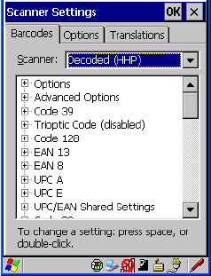
Chapter 5: Configuration
Decoded (HHP)
154 WORKABOUT PRO G2 Hand-Held With Windows Embedded CE 5.0 User Manual
Field Size/Char
Refer to page 143 for details.
5.11.3 Decoded (HHP)
5.11.3.1 Decoded (HHP) Scanner Options
Laser On Time
The value assigned to this parameter determines how long the laser will remain on
when the scan button or trigger is pressed.
Double-tapping on this parameter displays a dialog box in which you can enter a
value from 1 to 10.
5.11.3.2 Decoded (HHP) Advanced Options
Continuous Scan Mode
Setting this parameter to on keeps the laser on and continuously decoding as long as
the scanner button is pressed and held down.
Minimum Cancel Time
The value assigned to this parameter determines the time delay before the scanner is
turned off, once the scanner trigger or button is released. This gives the scanner a
minimum amount of time to complete its current decode before the scan is cancelled
when the user quickly triggers on/off.

WORKABOUT PRO G2 Hand-Held With Windows Embedded CE 5.0 User Manual 155
Chapter 5: Configuration
Decoded (HHP)
Low Power Timeout
To extend laser life, you can select the length of time the scanner remains active
following a successful decode. The scanner wakes from low power mode when a
bar code is scanned – a successful decode restores normal blinking.
When you double-tap on this parameter, a dialog box is displayed in which you can
choose a value of 30 sec, 1 min, 2 min or 3 min.
Note: This parameter is only used if the Trigger Mode has been set to Continu-
ous On and the hand-held is mounted in a fixed position; otherwise, ‘Low
Power Timeout’ is not used.
5.11.3.3 Code 39
Enabled
Setting this parameter to on enables “Code 39”.
Strip Start/Stop Chars
Codabar uses the characters A, B, C, and D as start and stop characters. Thus, the
first and last digits of a Codabar message must be A, B, C, or D, and the body of the
message should not contain these characters. Setting this parameter to on strips the
start and stop characters from this bar code.
Check Char
When this parameter is set to Validate only, the integrity of a “Code 39” symbol is
checked to ensure that it complies with specified algorithms.
If “Check Char” is set to Validate and Transmit, the check character is validated and
transmitted with the data.
Setting this parameter to None disables this function.
Minimum And Maximum Length
Minimum and Maximum lengths for the bar code can be set from 0 to 48. The
length of a code refers to the number of characters (i.e., human readable characters),
including check digit(s).

Chapter 5: Configuration
Decoded (HHP)
156 WORKABOUT PRO G2 Hand-Held With Windows Embedded CE 5.0 User Manual
Append
If this parameter enabled, any Code 39 bar code that contains a space as the first
character will be “stored in memory”. Once a Code 39 barcode containing a
non-space first character is scanned, this bar code will be appended to the bar codes
containing the spaces and the imager will transmit the ALL the data. The spaces are
then removed.
Pharmaceutical
This is a numeric (0-9) fixed length barcode used by Italian pharmacies. It is also
referred to as Code 32 Pharmacode and is a form of Code 39.
Full ASCII
If this parameter is enabled, the characters +, %, and / are used as escape characters.
The combination of an escape character and the next character is converted to an
equivalent ASCII character.
Field Size/Char
Refer to page 143 for details.
5.11.3.4 Trioptic Code
This code is used for labeling magnetic storage media.
Note: If you are scanning Code 32 Pharmaceutical codes, Trioptic Code must
be off.
5.11.3.5 Code 128
Enabled
Setting this parameter to on enables “Code 128”.
ISBT Concatenation
These codes are not concatenated by default. You need to set this parameter to on to
send concatenated code.
WORKABOUT PRO G2 Hand-Held With Windows Embedded CE 5.0 User Manual 157
Chapter 5: Configuration
Decoded (HHP)
Minimum And Maximum Length
The length of a code refers to the number of characters (i.e., human readable
characters), including check digit(s). Double-tapping on these parameters displays a
screen in which you can set the minimum and maximum allowable code lengths – 0
to 80.
Field Size/Char
Refer to page 143 for details.
5.11.3.6 EAN 13 Settings
Enabled
Set this parameter to on to enable “EAN 13”.
Check Digit
If you enable this parameter, a check digit is included with the decoded bar
code data.
Addendum Add-on 2 And Addendum Add-on 5
An addendum is a separate bar code, supplementary to the main bar code.
Enabling these parameters defines the length of the addendum bar code to either 2
or 5 characters.
Addendum Required
When this parameter is set to on, the scanner does not accept the main bar code
without an addendum.
Addendum Separator
“Addendum Separator” is a space that is added between the EAN 13 bar code and
the Add-on code/Addenda. When this parameter is set to on, the scanner does not
accept the main bar code without an addendum.
ISBN Translate
When this parameter (International Standard Book Number) is enabled, the first 3
characters (‘978’) are ignored and the checksum (0.9, ‘X’) is calculated on the
remaining characters.
Chapter 5: Configuration
Decoded (HHP)
158 WORKABOUT PRO G2 Hand-Held With Windows Embedded CE 5.0 User Manual
Prefix/Suffix
Refer to “Prefix/Suffix” beginning on page 144.
5.11.3.7 EAN 8
Enabled
Set this parameter to on to enable “EAN 8”.
Check Digit
If you enable this parameter, a check digit is included with the decoded bar
code data.
Addendum Add-on 2 And Addendum Add-on 5
An addendum is a separate bar code, supplementary to the main bar code.
Enabling these parameters defines the length of the addendum bar code to either
2 or 5 characters.
Addendum Required
When this parameter is set to on, the scanner does not accept the main bar code
without an addendum.
Addendum Separator
Addendum Separator is a space that is added between the EAN 13 bar code and the
Add-on code/Addenda. When this parameter is set to on, the scanner does not
accept the main bar code without an addendum.
Prefix/Suffix
Refer to “Prefix/Suffix” beginning on page 144.
5.11.3.8 UPC A Settings
Enabled
Set this parameter to on to enable “UPC A” bar code scanning recognition.
Check Digit
If you enable this parameter, a check digit is included with the decoded bar
code data.
WORKABOUT PRO G2 Hand-Held With Windows Embedded CE 5.0 User Manual 159
Chapter 5: Configuration
Decoded (HHP)
Transmit Number System
If this parameter is enabled, the number system digit is transmitted with the decoded
bar code data.
Addendum Add-on 2 And Addendum Add-on 5
An addendum is a separate bar code, supplementary to the main bar code.
Enabling these parameters defines the length of the addendum bar code to either
2 or 5 characters.
Addendum Required
When this parameter is set to on, the scanner does not accept the main bar code
without an addendum.
Addendum Separator
“Addendum Separator” is a space that is added between the UPC A bar code and the
Add-on code/Addenda. When this parameter is set to on, the scanner does not
accept the main bar code without an addendum.
Prefix/Suffix
Refer to “Prefix/Suffix” beginning on page 144.
5.11.3.9 UPC E Settings
Enabled
Set this parameter to on to enable “UPC E”.
Enabled UPC-E1
Set this parameter to on to allow “UPC-E1” (zero suppressed) bar code scans.
Expand
This parameter expands the UPC E code to a 12 digit UPC-A format.
Check Digit
If you enable this parameter, a check digit is included with the decoded bar
code data.

Chapter 5: Configuration
Decoded (HHP)
160 WORKABOUT PRO G2 Hand-Held With Windows Embedded CE 5.0 User Manual
Transmit Number System
If this parameter is enabled, the number system digit is transmitted with the decoded
bar code data.
Addendum Add-on 2 And Addendum Add-on 5
An addendum is a separate bar code, supplementary to the main bar code.
Enabling these parameters defines the length of the addendum bar code to either
2 or 5 characters.
Addendum Required
When this parameter is set to on, the scanner does not accept the main bar code
without an addendum.
Addendum Separator
“Addendum Separator” is a space that is added between the UPC E bar code and the
Add-on code/Addenda. When this parameter is set to on, the scanner does not
accept the main bar code without an addendum.
Prefix/Suffix
Refer to “Prefix/Suffix” beginning on page 144.
5.11.3.10 UPC/EAN Shared Settings
Extended Coupon Code
This parameter specifies whether or not the imager will read only UPC-A/EAN-13
bar codes that have addenda.
Note: The 2 or 5 digit addenda must be turned on/off, depending on the desired
behavior.
5.11.3.11 Code 93
Enabled
Set this parameter to on to enable “Code 93”.
WORKABOUT PRO G2 Hand-Held With Windows Embedded CE 5.0 User Manual 161
Chapter 5: Configuration
Decoded (HHP)
Minimum And Maximum Length
The length of a code refers to the number of characters (i.e., human readable
characters), including check digit(s). Double-tapping on these parameters displays a
screen in which you can set the minimum and maximum allowable code lengths – 0
to 80.
Field Size/Char
Refer to page 143 for details.
5.11.3.12 Codabar
Enabled
Set this parameter to on to enable “Codabar”.
Start/Stop Transmit
Codabar can use the following sets of characters as start and stop characters:
a, b, c, d
A, B, C, D
a, b, c, d, /, t, n, *, e
DC1, DC2, DC3, DC4
Thus, when a set is chosen, the first and last digits of a Codabar message must be
one of those characters and the body of the message should not contain these
characters. Setting this parameter to off strips the start and stop characters from this
bar code.
Check Char
When this parameter is set to Validate only, the integrity of a “Code 39” symbol is
checked to ensure that it complies with specified algorithms.
If “Check Char” is set to Validate and Transmit, the check character is validated and
transmitted with the data.
Setting this parameter to None disables this function.
Chapter 5: Configuration
Decoded (HHP)
162 WORKABOUT PRO G2 Hand-Held With Windows Embedded CE 5.0 User Manual
Concatenation
“Codabar” supports symbol concatenation. When you enable Concatenation, the
imager looks for a Codabar symbol with a “D” start character that is adjacent to a
symbol with a “D” stop character. In this case, the two messages are concatenated
into one with the “D” characters omitted.
Minimum And Maximum Length
The length of a code refers to the number of characters (i.e., human readable
characters), including check digit(s). Double-tapping on these parameters displays a
screen in which you can set the minimum and maximum allowable code lengths – 2
to 60.
Field Size/Char
Refer to page 143 for details.
5.11.3.13 MSI Plessey
Enabled
Set this parameter to on to enable MSI.
Enable Plessey
Set this parameter to on to enable Plessey.
Check Char
When this parameter is set to Validate only, the integrity of the symbol is checked to
ensure that it complies with specified algorithms.
If “Check Char” is set to Validate and Transmit, the check character is validated and
transmitted with the data.
Setting this parameter to None disables this function.
Minimum And Maximum Length
These parameters apply to MSI bar codes. The length of a code refers to the number
of characters (i.e., human readable characters), including check digit(s).
Double-tapping on these parameters displays a screen in which you can set the
minimum and maximum allowable code lengths – 4 to 48.
WORKABOUT PRO G2 Hand-Held With Windows Embedded CE 5.0 User Manual 163
Chapter 5: Configuration
Decoded (HHP)
Plessey Minimum And Plessey Maximum Length
These parameters apply to Plessey bar codes.The length of a code refers to the
number of characters (i.e., human readable characters), including check digit(s).
Double-tapping on these parameters displays a screen in which you can set the
minimum and maximum allowable code lengths – 4 to 48.
Field Size/Char
Refer to page 143 for details.
5.11.3.14 Code 11
Enabled
Set this parameter to on to enable “Code 11”.
Check Digits
Double-tapping on this parameter displays a dialog box in which you can choose
One Check Digit or Two check digits.
If this parameter is set to One Check Digit, it is assumed that the last digit is a check
digit. If it is set to Two Check Digits, it is assumed that the last two digits are check
digits.
Minimum And Maximum Length
The length of a code refers to the number of characters (i.e., human readable
characters), including check digit(s). Double-tapping on these parameters displays a
screen in which you can set the minimum and maximum allowable code lengths – 1
to 80.
Field Size/Char
Refer to page 143 for details.
5.11.3.15 Interleaved 2 of 5
Enabled
Set this parameter to on to enable “Interleaved 2 of 5”.
Chapter 5: Configuration
Decoded (HHP)
164 WORKABOUT PRO G2 Hand-Held With Windows Embedded CE 5.0 User Manual
Check Digit
When this parameter is set to Validate only, the integrity of a symbol is checked to
ensure that it complies with specified algorithms.
If “Check Digit” is set to Validate and Transmit, the check digit is validated and
transmitted with the data.
Setting this parameter to None disables this function.
Minimum And Maximum Length
The length of a code refers to the number of characters (i.e., human readable
characters), including check digit(s). Double-tapping on these parameters displays a
screen in which you can set the minimum and maximum allowable code lengths – 1
to 80.
Field Size/Char
Refer to page 143 for details.
5.11.3.16 Matrix 2 of 5
Enabled
Set this parameter to on to enable “Matrix 2 of 5”.
Minimum And Maximum Length
The length of a code refers to the number of characters (i.e., human readable
characters), including check digit(s). Double-tapping on these parameters displays a
screen in which you can set the minimum and maximum allowable code lengths – 1
to 80.
Field Size/Char
Refer to page 143 for details.
5.11.3.17 IATA 2 of 5
Enabled
Set this parameter to on to enable “IATA 2 of 5”.
WORKABOUT PRO G2 Hand-Held With Windows Embedded CE 5.0 User Manual 165
Chapter 5: Configuration
Decoded (HHP)
Minimum And Maximum Length
The length of a code refers to the number of characters (i.e., human readable
characters), including check digit(s). Double-tapping on these parameters displays a
screen in which you can set the minimum and maximum allowable code lengths – 1
to 48.
Field Size/Char
Refer to page 143 for details.
5.11.3.18 Discrete 2 of 5
Enabled
Set this parameter to on to enable “Discrete 2 of 5”.
Minimum And Maximum Length
The length of a code refers to the number of characters (i.e., human readable
characters), including check digit(s). Double-tapping on these parameters displays a
screen in which you can set the minimum and maximum allowable code lengths – 1
to 48.
Field Size/Char
Refer to page 143 for details.
5.11.3.19 Telepen
Enabled
Set this parameter to on to enable “Telepen”.
Output
If you choose AIM Output, the imager reads symbols with start/stop pattern 1 and
decodes them as standard full ASCII (start/stop pattern 1). If you choose Original
Output, the imager reads symbols with start/stop pattern 1 and decodes them as
compressed numeric with optional full ASCII (start/stop pattern 2).
Chapter 5: Configuration
Decoded (HHP)
166 WORKABOUT PRO G2 Hand-Held With Windows Embedded CE 5.0 User Manual
Minimum And Maximum Length
The length of a code refers to the number of characters (i.e., human readable
characters), including check digit(s). Double-tapping on these parameters displays a
screen in which you can set the minimum and maximum allowable code lengths – 1
to 60.
Field Size/Char
Refer to page 143 for details.
5.11.3.20 RSS Code (Reduced Space Symbology)
Enable
Setting this parameter to on enables “RSS Code” scanning capability.
Enable RSS Limited
‘RSS-Limited” is restricted, in that it can only encode 14 digit GTINs (global trade
item number) that begin with either a 0 or a 1. It is not stackable and is not designed
to be read omni-directionally.
Enable RSS Expanded
“RSS Expanded” uses the same application identifiers as UCC/EAN-128 codes but
they can be split into sections and stacked several rows high, reducing the length of
the symbol, while increasing the capacity of data that can be stored. “RSS
Expanded” code can be omni-directionally scanned.
Minimum And Maximum Length
The length of a code refers to the number of characters (i.e., human readable
characters), including check digit(s). Double-tapping on these parameters displays a
screen in which you can set the minimum and maximum allowable code lengths – 1
to 74.
Field Size/Char
Refer to page 143 for details.

WORKABOUT PRO G2 Hand-Held With Windows Embedded CE 5.0 User Manual 167
Chapter 5: Configuration
Decoded (HHP)
5.11.3.21 PosiCode (Reduced Space Symbology)
Enable
Setting this parameter to on enables “PosiCode” scanning capability.
PosiCode
“PosiCode” is a “position” based symbology. A position based symbology
de-couples the widths of the bars from their positions. The centers of the bars are
specified to be laid out on a grid of equally spaced parallel lines. The distance
between these grid lines is called the G-dimension and is analogous to the
X-dimension of conventional bar codes.
There are two variations of this code: PosiCode A, and PosiCode B. The options
available with this parameter allow to choose A and B, A and B and Limited A or A
and B and Limited B.
Minimum And Maximum Length
The length of a code refers to the number of characters (i.e., human readable
characters), including check digit(s). Double-tapping on these parameters displays a
screen in which you can set the minimum and maximum allowable code lengths – 1
to 80.
Field Size/Char
Refer to page 143 for details.
5.11.3.22 Composite
Important: To successfully read this type of bar code, the two types of
symbologies included in a composite bar code must be enabled.
A composite symbol includes multi-row 2D components making it compatible with
linear and area CCD scanners along with linear and rastering laser scanners.
The options available for this parameter represent multi-level components of a
composite symbol.
GS1 128
“GS1 128” is the GS1 implementation of the Code 128 barcode specification. The
former correct name was UCC/EAN-128.
Chapter 5: Configuration
Decoded (HHP)
168 WORKABOUT PRO G2 Hand-Held With Windows Embedded CE 5.0 User Manual
“GS1-128” uses a series of Application Identifiers to include additional data such as
best before dates, batch numbers, quantities, weights and many other attributes
needed by the user.
EAN/UCC 128 Emulation
The options in this parameter allow you to turn this emulation on or off, or to enable
RSS Emulation.
Minimum And Maximum Length
The length of a code refers to the number of characters (i.e., human readable
characters), including check digit(s). Double-tapping on these parameters displays a
screen in which you can set the minimum and maximum allowable code lengths – 1
to 2435.
5.11.3.23 TLC-39
This composite component integrates MicroPDF417 with the linear code.
Enabled
Setting this parameter to on enables this parameter.
Field Size/Char
Refer to page 143 for details.
5.11.3.24 PDF-417
Enabled
Set this parameter to on to enable “PDF-417”.
Minimum And Maximum Length
The length of a code refers to the number of characters (i.e., human readable
characters), including check digit(s). Double-tapping on these parameters displays a
screen in which you can set the minimum and maximum allowable code lengths – 1
to 2750.
Field Size/Char
Refer to page 143 for details.
WORKABOUT PRO G2 Hand-Held With Windows Embedded CE 5.0 User Manual 169
Chapter 5: Configuration
Decoded (HHP)
5.11.3.25 Micro PDF-417
Enabled
Set this parameter to on to enable “Micro PDF-417”.
Minimum And Maximum Length
The length of a code refers to the number of characters (i.e., human readable
characters), including check digit(s). Double-tapping on these parameters displays a
screen in which you can set the minimum and maximum allowable code lengths – 1
to 366.
Field Size/Char
Refer to page 143 for details.
5.11.3.26 Code 16K
The “Code 16K” bar code is a multiple-row bar code that can encode the full ASCII
character set below ASCII 128. It uses existing UPC and Code 128 character set
patterns. Up to 77 full ASCII characters or 154 numeric characters can be encoded
into 2 to 16 rows. Each row is divided by a separator bar. The top and bottom of the
symbol also have separator bars that extend to the ends of the minimum quiet zones.
Enabled
Set this parameter to on to enable “Code 16K”.
Minimum And Maximum Length
The length of a code refers to the number of characters (i.e., human readable
characters), including check digit(s). Double-tapping on these parameters displays a
screen in which you can set the minimum and maximum allowable code lengths – 1
to 160.
Field Size/Char
Refer to page 143 for details.
Chapter 5: Configuration
Decoded (HHP)
170 WORKABOUT PRO G2 Hand-Held With Windows Embedded CE 5.0 User Manual
5.11.3.27 Code 49
The “Code 49” bar code is a multiple-row bar code that can encode the full ASCII
character set below ASCII 128. Up to 49 alphanumeric characters or 81 numeric
characters can be encoded into two to eight rows. Each row is divided by a separator
bar. The top and bottom of the symbol also have separator bars that extend to the
ends of the minimum quiet zones.
Enabled
Set this parameter to on to enable “Code 49”.
Minimum And Maximum Length
The length of a code refers to the number of characters (i.e., human readable
characters), including check digit(s). Double-tapping on these parameters displays a
screen in which you can set the minimum and maximum allowable code lengths – 1
to 81.
Field Size/Char
Refer to page 143 for details.
5.11.3.28 Codablock
Enable
Set this parameter to on to enable “Codablock”.
Minimum And Maximum Length
The length of a code refers to the number of characters (i.e., human readable
characters), including check digit(s). Double-tapping on these parameters displays a
screen in which you can set the minimum and maximum allowable code lengths – 1
to 2048.
Field Size/Char
Refer to page 143 for details.
5.11.3.29 2D Data Matrix
Enable
Set this parameter to on to enable “2D Data Matrix”.
WORKABOUT PRO G2 Hand-Held With Windows Embedded CE 5.0 User Manual 171
Chapter 5: Configuration
Decoded (HHP)
Minimum And Maximum Length
The length of a code refers to the number of characters (i.e., human readable
characters), including check digit(s). Double-tapping on these parameters displays a
screen in which you can set the minimum and maximum allowable code lengths – 1
to 1500.
Field Size/Char
Refer to page 143 for details.
5.11.3.30 2D QR Code
Enabled
Set this parameter to on to enable “2D QR Code”.
Minimum And Maximum Length
The length of a code refers to the number of characters (i.e., human readable
characters), including check digit(s). Double-tapping on these parameters displays a
screen in which you can set the minimum and maximum allowable code lengths – 1
to 3500.
Field Size/Char
Refer to page 143 for details.
5.11.3.31 2D Maxicode
Enabled
Set this parameter to on to enable “2D Maxicode”.
Minimum And Maximum Length
The length of a code refers to the number of characters (i.e., human readable
characters), including check digit(s). Double-tapping on these parameters displays a
screen in which you can set the minimum and maximum allowable code lengths – 1
to 150.
Field Size/Char
Refer to page 143 for details.
Chapter 5: Configuration
Decoded (HHP)
172 WORKABOUT PRO G2 Hand-Held With Windows Embedded CE 5.0 User Manual
5.11.3.32 2D Aztec
Enabled
Set this parameter to on to enable “2D Aztec”.
Aztec Runes
Aztec Runes, the smallest type of Aztec Code symbol, has the ability to encode a
very short license plate message.
Minimum And Maximum Length
The length of a code refers to the number of characters (i.e., human readable
characters), including check digit(s). Double-tapping on these parameters displays a
screen in which you can set the minimum and maximum allowable code lengths – 1
to 3750.
Field Size/Char
Refer to page 143 for details.
5.11.3.33 Postal: PlaNET
Enabled
Set this parameter to on to enable “Postal: PlaNET”.
Check Digit
If enabled, the check digit will be transmitted at the end of the scanned data.
Field Size/Char
Refer to page 143 for details.
5.11.3.34 Postal: PostNET
Enabled
Set this parameter to on to enable “Postal: PostNET”.
Check Digit
If enabled, the check digit will be transmitted at the end of the scanned data.
WORKABOUT PRO G2 Hand-Held With Windows Embedded CE 5.0 User Manual 173
Chapter 5: Configuration
Decoded (HHP)
Field Size/Char
Refer to page 143 for details.
5.11.3.35 Postal: Australian
Enabled
Set this parameter to on to enable “Postal: Australian”.
Field Size/Char
Refer to page 143 for details.
5.11.3.36 Postal: Canadian
Enabled
Set this parameter to on to enable “Postal: Canadian”.
Field Size/Char
Refer to page 143 for details.
5.11.3.37 Postal: China
Enabled
Set this parameter to on to enable “Postal: China”.
Minimum And Maximum Length
The length of a code refers to the number of characters (i.e., human readable
characters), including check digit(s). Double-tapping on these parameters displays a
screen in which you can set the minimum and maximum allowable code lengths – 2
to 80.
Field Size/Char
Refer to page 143 for details.
5.11.3.38 Postal: Japanese
Enabled
Set this parameter to on to enable “Postal: Japanese”.
Chapter 5: Configuration
Decoded (HHP)
174 WORKABOUT PRO G2 Hand-Held With Windows Embedded CE 5.0 User Manual
Field Size/Char
Refer to page 143 for details.
5.11.3.39 Postal: Kix
Enabled
Set this parameter to on to enable “Postal: Kix”.
Field Size/Char
Refer to page 143 for details.
5.11.3.40 Postal: Korean
Enabled
Set this parameter to on to enable “Postal: Korean”.
Minimum And Maximum Length
The length of a code refers to the number of characters (i.e., human readable
characters), including check digit(s). Double-tapping on these parameters displays a
screen in which you can set the minimum and maximum allowable code lengths – 2
to 48.
Field Size/Char
Refer to page 143 for details.
5.11.3.41 Postal: Royal
Enabled
Set this parameter to on to enable “Postal: Royal”.
Field Size/Char
Refer to page 143 for details.
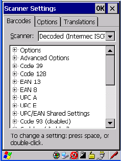
WORKABOUT PRO G2 Hand-Held With Windows Embedded CE 5.0 User Manual 175
Chapter 5: Configuration
Decoded (Intermec ISCP)
5.11.4 Decoded (Intermec ISCP)
• Tap on the Scanner drop-down menu, and choose Decoded (Intermec
ISCP).
5.11.4.1 Decoded (Intermec ISCP) Options
Laser On Time
The value assigned to this parameter determines how long the laser will remain on
when the scan button or trigger is pressed.
Double-tapping on this parameter displays a dialog box in which you can enter a
value between 1 and 10 seconds.
5.11.4.2 Decoded (Intermec ISCP) Advanced Options
Continuous Scan Mode
Setting this parameter to ‘on’ keeps the laser on and continuously decoding as long
as the scanner button is pressed and held down.
Minimum Cancel Time
The value assigned to this parameter determines the time delay before the scanner is
turned off, once the scanner trigger or button is released. This gives the scanner a
minimum amount of time to complete its current decode before the scan is cancelled
when the user quickly triggers on/off.

Chapter 5: Configuration
Decoded (Intermec ISCP)
176 WORKABOUT PRO G2 Hand-Held With Windows Embedded CE 5.0 User Manual
Low Power Timeout
To extend laser life, you can select the length of time the scanner remains active
following a successful decode. The scanner wakes from low power mode when a
bar code is scanned – a successful decode restores normal blinking.
When you double-tap on this parameter, a dialog box is displayed in which you can
choose a value of 30 sec, 1 min, 2 min or 3 min.
Note: This parameter is only used if the Trigger Mode has been set to Continu-
ous On and the hand-held is mounted in a fixed position; otherwise, ‘Low
Power Timeout’ is not used.
Parameter Scanning
Setting this parameter to Enabled allows decoding of parameter bar codes.
Same Read Validate
The data is only transmitted after repeated reads give the same result. The
value assigned at this parameter determines the number of reads required, from
0 to 10 times.
Same Read Timeout
Prevents the same bar code from being read more than once. The value assigned
determines after what time period the scanner will timeout, from 0 to 2550 msec.
Diff Read Timeout
Prevents unwanted reading of other bar codes on the same label. The value assigned
determines after what time period the scanner will timeout, from 0 to 2550 msec.
5.11.4.3 Code 39
Enable
Setting this parameter to on enables “Code 39”.
Full ASCII
If this parameter is enabled, the characters +, %, and / are used as escape
characters. The combination of an escape character and the next character
is converted to an equivalent ASCII character.

WORKABOUT PRO G2 Hand-Held With Windows Embedded CE 5.0 User Manual 177
Chapter 5: Configuration
Decoded (Intermec ISCP)
Reading Range
Determines the reading distance from which a bar code can be successfully scanned.
The default setting, Extended, allows for increased reading distance.
Start/Stop Transmit
Setting this parameter to on enables the transmission of start and stop characters,
which are usually not transmitted. Code 39 can start and end with either a * or a $
character (see also next parameter Accepted Start Char).
Accepted Start Char
This parameter allows the user the option of using one of the two start/stop
characters or both ($ char, * char, $ and * char).
Check Digit Verification
Uses the specified algorithm of the option you've chosen to ensure the integrity of
the symbol data before transmitting. If the data does not contain that algorithm, the
data is not transmitted. The available options are: Disabled, MOD 43 Check, French
CIP, or Italian CIP.
Notes: French CIP (French pharmaceutical) is only used with bar codes contain-
ing 7 characters.
Italian CIP (Italian pharmaceutical) is also known as Code 32. It is trans-
mitted as a standard Code 39 if checksum is not validated.
Transmit Check Digit
If the check digit is to be transmitted with the data, this parameter must be enabled.
Minimum Length
Minimum lengths for the bar code can be set from 0 to 255. The length of a code
refers to the number of characters (i.e., human readable characters), including check
digit(s).
Field Size/Char
Refer to page 143 for details.

Chapter 5: Configuration
Decoded (Intermec ISCP)
178 WORKABOUT PRO G2 Hand-Held With Windows Embedded CE 5.0 User Manual
5.11.4.4 Code 128
Enable
Setting this parameter to on enables “Code 128”.
GS1-128
“GS1-128” is the GS1 implementation of the Code 128 barcode specification. The
former correct name was UCC/EAN-128.
GS1-128 Identifier
“GS1-128 Identifier” allows the AIM ID " ]C1" for EAN 128 to be transmitted or
removed. By default, this identifier is transmitted if EAN 128 is enabled.
GTIN Compliant
GTIN (global trade item number) processing transmits EAN 128 as the 14-character
EAN/UCC GTIN. To use GTIN processing, you must activate the EAN 128
symbology.
Important: When EAN 128 and GTIN processing are both activated, it is not
possible to read normal EAN 128 Codes.
FNC1 Conversion
“FNC1 Conversion” allows the embedded FNC1 character to be converted to
another character for applications that cannot use the default <GS> Group Separator
or hex (1d).
Double-tapping on this option displays a dialog box listing the allowable
range – 0 to 255.
Enable ISBT 128
To successfully scan this type of bar code (International Society of Blood
Transfusion), this option must be set to on. If you enable this type of bar code, Code
128/EAN 128 is deactivated to avoid any confusion.
ISBT Concat Transmit
The codes are not concatenated by default. You need to choose one of the options
provided for this parameter to send concatenated code. Choosing Only
Concatenated Codes transmits only concatenated codes—single codes will not be

WORKABOUT PRO G2 Hand-Held With Windows Embedded CE 5.0 User Manual 179
Chapter 5: Configuration
Decoded (Intermec ISCP)
transmitted. Choosing Concatenated or Single transmits single codes or
concatenated codes. If only one code of a pair is read, that code will be transmitted
as a single code. If both codes in a pair are detected, they will be concatenated
provided that ISBT Concat Any Pair (see below) is enabled.
ISBT Concat Any Pair
Enabling this parameter causes all code pairs that can be, to be concatenated even if
they do not comply with Section 4.1 of the “ISBT 128 Bar Code Symbology and
Application Specification for Labeling of Whole Blood and Blood Components”
(June 2000, Version 1.2.1).
Reading Range
Determines the reading distance from which a bar code can be successfully scanned.
The default setting Extended, allows for increased reading distance.
Check Digit Verification
The available options for this parameter are Disabled or French CIP. This parameter
uses the specified algorithm of the option you've chosen to ensure the integrity of
the symbol data before transmitting. If the data does not contain that algorithm, the
data is not transmitted.
Note: French CIP (French pharmaceutical) is only used with bar codes contain-
ing 7 characters.
Minimum Length
Minimum lengths for the bar code can be set from 0 to 255. The length of a code
refers to the number of characters (i.e., human readable characters), including
check digit(s).
Field Size/Char
Refer to page 143 for details.
5.11.4.5 EAN 13 Settings
Enabled
Set this parameter to on to enable “EAN 13”.
Chapter 5: Configuration
Decoded (Intermec ISCP)
180 WORKABOUT PRO G2 Hand-Held With Windows Embedded CE 5.0 User Manual
ISBN Conversion
When this parameter (International Standard Book Number) is enabled, the first 3
characters (‘978’) are ignored and the checksum (0.9, ‘X’) is calculated on the
remaining characters.
Transmit Check Digit
If the check digit is to be transmitted with the data, this parameter must be enabled.
Prefix/Suffix
Refer to “Prefix/Suffix” beginning on page 144.
5.11.4.6 EAN 8
Enabled
Set this parameter to on to enable “EAN 8”.
Transmit Check Digit
If the check digit is to be transmitted with the data, this parameter must be enabled.
Convert To EAN 13
If this parameter is enabled, an EAN 8 bar code is converted to EAN 13.
Prefix/Suffix
Refer to “Prefix/Suffix” beginning on page 144.
5.11.4.7 UPC A Settings
Enabled
Set this parameter to on to enable “UPC A” bar code scanning recognition.
Transmit Check Digit
If the check digit is to be transmitted with the data, this parameter must be enabled.
Transmit Number System
If this parameter is enabled, the number system digit is transmitted with the decoded
bar code data.
WORKABOUT PRO G2 Hand-Held With Windows Embedded CE 5.0 User Manual 181
Chapter 5: Configuration
Decoded (Intermec ISCP)
Convert To EAN 13
If this parameter is enabled, a UPC A bar code is converted to EAN 13.
Prefix/Suffix
Refer to “Prefix/Suffix” beginning on page 144.
5.11.4.8 UPC E Settings
Enabled
Set this parameter to on to enable “UPC E”.
Enable UPC-E1
Set this parameter to on to allow “UPC-E1” (zero suppressed) bar code scans.
Transmit Check Digit
If the check digit is to be transmitted with the data, this parameter must be enabled.
Transmit Number System
If this parameter is enabled, the number system digit is transmitted with the decoded
bar code data.
Convert To UPC-A
This parameter converts UPC E (zero suppressed) decoded data to UPC A format
before transmission. After conversion, data follows UPC A format and is affected
by UPC A programming selections (e.g. Check Digit).
Prefix/Suffix
Refer to “Prefix/Suffix” beginning on page 144.
5.11.4.9 UPC/EAN Shared Settings
The setting assigned to the “Addendum” parameter associated with this option is
shared across all UPC and EAN bar codes.

Chapter 5: Configuration
Decoded (Intermec ISCP)
182 WORKABOUT PRO G2 Hand-Held With Windows Embedded CE 5.0 User Manual
Addendum
An addendum is a separate bar code, supplementary to the main bar code.
This parameter provides two options: Not Required but Transmitted if Read or
Required and Transmitted.
• Double-tap on Addendum to display a dialog box listing your options.
• Highlight an item, and tap on OK.
When “Addendum” is set to Not Required but Transmitted if Read, the scanner
searches for an addendum and if one exists, appends it to the main bar code. When
the parameter is set to Required and Transmitted, the scanner does not accept the
main bar code without an addendum.
Addendum Add-on 2 And Addendum Add-on 5
Enabling these parameters sets the length of the addendum bar code to either 2 or
5 characters.
GTIN Compliant
GTIN (global trade item number) processing transmits EAN 128 as the 14-character
EAN/UCC GTIN. To use GTIN processing, you must activate the EAN 128
symbology.
Important: When EAN 128 and GTIN processing are both activated, it is not
possible to read normal EAN 128 Codes.
Reading Range
This parameter determines the reading distance from which a bar code can be
successfully scanned. The default setting, Extended, allows for increased
reading distance.
5.11.4.10 Code 93
Enabled
Set this parameter to on to enable “Code 93”.
WORKABOUT PRO G2 Hand-Held With Windows Embedded CE 5.0 User Manual 183
Chapter 5: Configuration
Decoded (Intermec ISCP)
Minimum Length
Minimum lengths for the bar code can be set from 0 to 255. The length of a code
refers to the number of characters (i.e., human readable characters), including
check digit(s).
Field Size/Char
Refer to page 143 for details.
5.11.4.11 Codabar
Enabled
Set this parameter to on to enable “Codabar”.
Start/Stop Transmit
Codabar can use the following sets of characters as start and stop characters:
a, b, c, d
A, B, C, D
a, b, c, d, /, t, n, *, e
DC1, DC2, DC3, DC4
Thus, when a set is chosen, the first and last digits of a Codabar message must be
one of those characters and the body of the message should not contain these
characters. Setting this parameter to Not Transmitted strips the start and stop
characters from this bar code.
CLSI Library System
When enabled, spaces are inserted after characters 1, 5, 10 in the 14-character label
(used in the USA by libraries using the CLSI system).
Check Digit Verification
When enabled, this parameter checks the integrity of a symbol to ensure it complies
with a specified algorithm – either USS (Uniform Symbology Specification) or
OPCC (Optical Product Code Council).
Transmit Check Digit
If the check digit is to be transmitted with the data, this parameter must be enabled.
Chapter 5: Configuration
Decoded (Intermec ISCP)
184 WORKABOUT PRO G2 Hand-Held With Windows Embedded CE 5.0 User Manual
Set Length L1, Set Length L2, And Set Length L3
Lengths for “Codabar” can be set from 0 to 255. The length of a code refers to the
number of characters (i.e., human readable characters), including check digit(s).
Double-tapping on these parameters displays dialog boxes where you can define the
code length that will be recognized by your scanner.
Length Mode
You can choose to set L1 as Minimum Length or L1,L2,L3 as Fixed Length.
Field Size/Char
Refer to page 143 for details.
5.11.4.12 MSI Plessey
Enabled
Set this parameter to on to enable “MSI”.
Enable Plessy
Set this parameter to on to enable “Plessy”.
Check Digit Verification
The available options for this parameter are MOD 10 Check and Double MOD 10
Check. This parameter uses the specified algorithm of the option you've chosen to
ensure the integrity of the symbol data before transmitting. If the data does not
contain that algorithm, the data is not transmitted.
Transmit Check Digit
If the check digit is to be transmitted with the data, this parameter must be enabled.
Plessy Transmit Check Digit
If the check digit is to be transmitted with the Plessy data, this parameter must
be enabled.
Minimum Length
Minimum lengths for the bar code can be set from 0 to 255. The length of a code
refers to the number of characters (i.e., human readable characters), including
check digit(s).
WORKABOUT PRO G2 Hand-Held With Windows Embedded CE 5.0 User Manual 185
Chapter 5: Configuration
Decoded (Intermec ISCP)
Plessy Minimum Length
Minimum lengths for the Plessy bar code can be set from 0 to 255. The length of a
code refers to the number of characters (i.e., human readable characters), including
check digit(s).
Field Size/Char
Refer to page 143 for details.
5.11.4.13 Code 11
Enabled
Set this parameter to on to enable “Code 11”.
Check Digit Verification
The available options for this parameter are MOD 10 Check and Double MOD 10
Check.This parameter uses the specified algorithm of the option you've chosen to
ensure the integrity of the symbol data before transmitting. If the data does not
contain that algorithm, the data is not transmitted.
Transmit Check Digit
If the check digit is to be transmitted with the data, this parameter must be enabled.
Minimum Length
Minimum lengths for the bar code can be set from 0 to 255. The length of a code
refers to the number of characters (i.e., human readable characters), including
check digit(s).
Field Size/Char
Refer to page 143 for details.
5.11.4.14 Interleaved 2 of 5
Enabled
Set this parameter to on to enable “Interleaved 2 of 5”.

Chapter 5: Configuration
Decoded (Intermec ISCP)
186 WORKABOUT PRO G2 Hand-Held With Windows Embedded CE 5.0 User Manual
Reading Range
This parameter determines the reading distance from which a bar code can be
successfully scanned. The default setting, Extended, allows for increased
reading distance.
Check Digit Verification
The available options for this parameter are Disabled, MOD 10 Check and French
CIP. “Check Digit Verification” uses the specified algorithm of the option you've
chosen to ensure the integrity of the symbol data before transmitting. If the data does
not contain that algorithm, the data is not transmitted.
Note: French CIP (French pharmaceutical) is only used with bar codes contain-
ing 7 characters.
Transmit Check Digit
If the check digit is to be transmitted with the data, this parameter must be enabled.
Set Length L1, Set Length L2, And Set Length L3
Lengths for “Interleaved 2 of 5” can be set from 0 to 255. The length of a code
refers to the number of characters (i.e., human readable characters), including
check digit(s).
Double-tapping on these parameters displays dialog boxes where you can define the
code length that will be recognized by your scanner.
Length Mode
You can chose to set L1 as Minimum Length or L1,L2,L3 as Fixed Length.
Field Size/Char
Refer to page 143 for details.
5.11.4.15 Matrix 2 of 5
Enabled
Set this parameter to on to enable “Matrix 2 of 5”.
WORKABOUT PRO G2 Hand-Held With Windows Embedded CE 5.0 User Manual 187
Chapter 5: Configuration
Decoded (Intermec ISCP)
Minimum Length
Minimum lengths for the bar code can be set from 0 to 255. The length of a code
refers to the number of characters (i.e., human readable characters), including
check digit(s).
Field Size/Char
Refer to page 143 for details.
5.11.4.16 Discrete 2 of 5
Enabled
Set this parameter to on to enable “Discrete 2 of 5”.
Standard 2 of 5 Format
This parameter allows you to choose a standard format – either Identicon (6
start/stop bars) or Computer Identics (4 start/stop bars).
Check Digit Verification
The available options for this parameter are Disabled and MOD 10 Check. “Check
Digit Verification” uses the specified algorithm of the option you've chosen to
ensure the integrity of the symbol data before transmitting. If the data does not
contain that algorithm, the data is not transmitted.
Transmit Check Digit
If the check digit is to be transmitted with the data, this parameter must be enabled.
Set Length L1, Set Length L2, And Set Length L3
Lengths for “Discrete 2 of 5” can be set from 0 to 255. The length of a code refers to
the number of characters (i.e., human readable characters), including check digit(s).
Double-tapping on these parameters displays dialog boxes where you can define the
code length that will be recognized by your scanner.
Length Mode
You can chose to set L1 as Minimum Length or L1,L2,L3 as Fixed Length.
Field Size/Char
Refer to page 143 for details.
Chapter 5: Configuration
Decoded (Intermec ISCP)
188 WORKABOUT PRO G2 Hand-Held With Windows Embedded CE 5.0 User Manual
5.11.4.17 Telepen
Enabled
Set this parameter to on to enable “Telepen”.
Format
This parameter allows you to set the bar code character format to either ASCII
or Numeric.
Minimum Length
Minimum lengths for the bar code can be set from 0 to 255. The length of a code
refers to the number of characters (i.e., human readable characters), including
check digit(s).
Field Size/Char
Refer to page 143 for details.
5.11.4.18 RSS Code (Reduced Space Symbology)
Enable
Setting this parameter to on enables “RSS Code” scanning capability.
Enable RSS-14
RSS-14 code can be either purely linear or split in half with one half stacked on top
of the other half. Stacking the code reduces the bar code length, and providing the
nominal height of the code is maintained, it can be omni-directionally scanned.
Enable RSS Limited
“RSS-Limited” is restricted, in that it can only encode 14 digit GTINs (global trade
item number) that begin with either a 0 or a 1. It is not stackable and is not designed
to be read omni-directionally.
Enable RSS Expanded
“RSS Expanded” uses the same application identifiers as UCC/EAN-128 codes but
they can be split into sections and stacked several rows high, reducing the length of
the symbol, while increasing the capacity of data that can be stored. “RSS
Expanded” code can be omni-directionally scanned.
WORKABOUT PRO G2 Hand-Held With Windows Embedded CE 5.0 User Manual 189
Chapter 5: Configuration
Decoded (Intermec ISCP)
Field Size/Char
Refer to page 143 for details.
5.11.4.19 PDF-417
Enabled
Set this parameter to on to enable “PDF-417”.
Field Size/Char
Refer to page 143 for details.
5.11.4.20 Micro PDF-417
Enabled
Set this parameter to on to enable “Micro PDF-417”.
Code 128 Emulation
When this parameter is enabled, the scanner transmits data from certain Micro
PDF-417 symbols as if it was encoded in Code 128 symbols.
If Code 128 Emulation is enabled, the following Micro PDF-417 symbols are
transmitted with one of the following prefixes:
]C1if the first codeword is 903-907, 912, 914, 915
]C2if the first codeword is 908 or 909
]C0if the first codeword is 910 or 911
If Code 128 Emulation is set to off, the Micro PDF-417 symbols are transmitted
with one of the following prefixes:
]L3if the first codeword is 903-907, 912, 914, 915
]L4if the first codeword is 908 or 909
]L5if the first codeword is 910 or 911
Field Size/Char
Refer to page 143 for details.
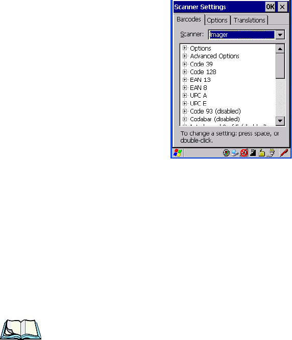
Chapter 5: Configuration
Imager
190 WORKABOUT PRO G2 Hand-Held With Windows Embedded CE 5.0 User Manual
5.11.4.21 Codablock
Enable Codablock A
Set this parameter to on to enable “Codablock type A”.
Enable Codablock F
Set this parameter to on to enable “Codablock type F”.
Field Size/Char
Refer to page 143 for details.
5.11.5 Imager
• Tap on the Scanner drop-down menu, and choose Imager.
5.11.5.1 Imager Options
TekImager Enabled
Setting this option to on enables the imager installed in your hand-held.
Continuous Scan Mode
Setting this parameter to on keeps image capture active and continuously decoding
as long as the scanner button is pressed and held down.
Center Bar Code Only
Note: This parameter must be disabled when reading Composite bar codes.

WORKABOUT PRO G2 Hand-Held With Windows Embedded CE 5.0 User Manual 191
Chapter 5: Configuration
Imager
When more than one bar code is visible in a single snap shot, this parameter allows
you to specify that only the centre image within the imager framing marker be read.
When this parameter is set to on, the target dot is pointed at the centre image and
only that image is returned.
Max Number Barcodes
This parameter specifies the maximum number of bar codes the imager will attempt
to decode in an image. A maximum of 6 bar codes can be decoded at one time.
Barcodes Must Decode
This parameter specifies the minimum number of bar codes that the imager must
decode in order to report success.
Note: This number must be less than the number of bar codes assigned to
“Max Number Barcodes”. The driver validates and reassigns the value
if necessary.
Window Width
“Window Width” determines the width of the captured image in pixels.
Note: The driver will validate and reassign the value assigned to this parameter,
if necessary; the driver will also use the Window Width value to horizon-
tally center the image in the field of view.
Window Height
This parameter determines the height of the captured image in pixels.
Note: The driver will validate and reassign the value assigned to this parameter,
if necessary; the driver will also use “Window Height” value to vertically
center the image in the field of view.
Dot Time (msec)
The value selected for “Dot Time (msec)” determines (in milliseconds) how long
the targeting dot remains on before the scanner begins capturing images. When you
double-tap on this parameter, a dialog box is displayed in which you can enter a
value of between 0 and 3000. A value of 0 disables the target dot.

Chapter 5: Configuration
Imager
192 WORKABOUT PRO G2 Hand-Held With Windows Embedded CE 5.0 User Manual
5.11.5.2 Imager Advanced Options
Important: Do not adjust the advanced options without first consulting Psion
Teklogix technical support.
Factory Defaults On Reboot
The value assigned to this parameter determines whether or not the driver will
restore the factory defaults to the imager device on the next reboot.
Note: The driver will default the imager device on a ‘clean’ reset, regardless of
the value of this parameter.
Min Scan Duration
This parameter defines the minimum amount of time in seconds that the imager will
scan when the trigger is pressed and held down without successful decode.
Note: The actual scan duration when the trigger is pressed relies on the value
assigned to Captures Per HW Trigger, below.
Captures Per HW Trigger
The value assigned to this parameter determines the number of captures the imager
device will take while the imager's internal hardware trigger is held down.
Note: This parameter, together with “Min Scan Duration”, determines the
actual scan duration. When the scan trigger is pressed and held down, the
driver starts a timer based on the value of “Min Scan Duration” and also
sends a command to emulate the hardware trigger. When completed, if the
time has not yet expired, it will send another command to the imager
device, forcing the imager to flash again using the value assigned to
“Captures Per HW Trigger”.
Auto Exposure
Important: This parameter value should only be changed by qualified Psion
Teklogix personnel. It should be left at the default value – ‘on’.