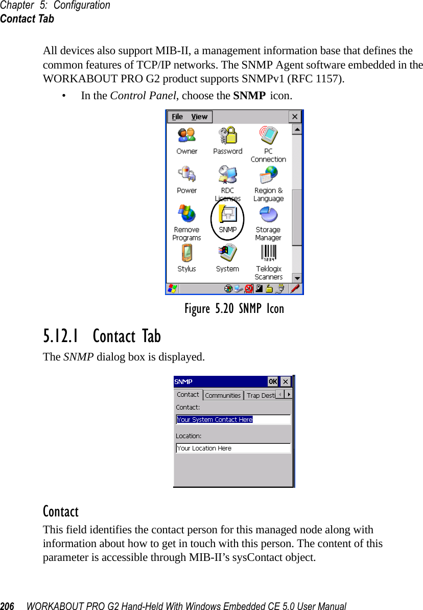
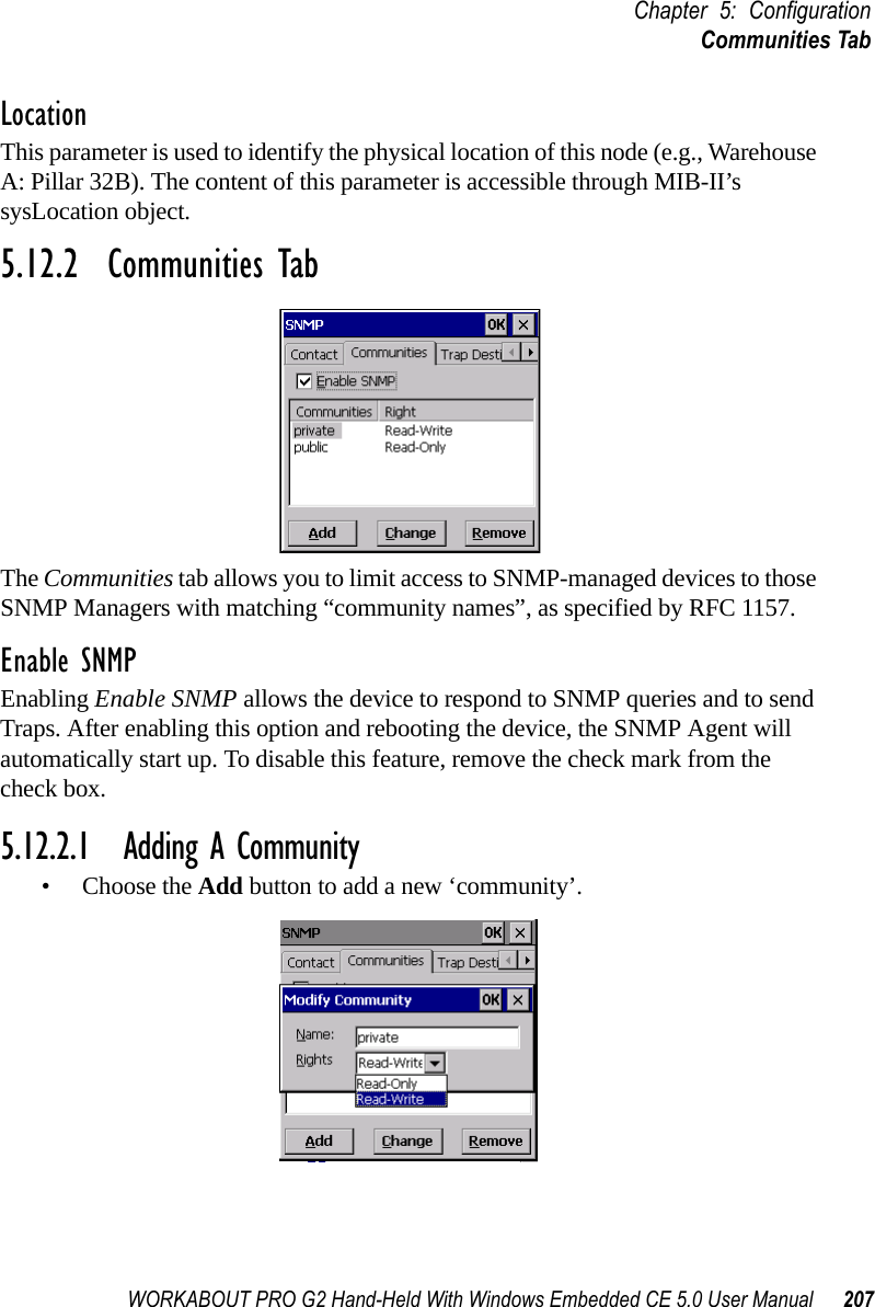
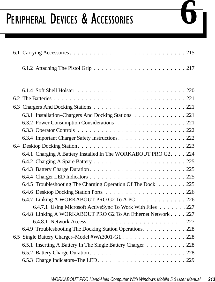
Psion 7527RA2041 802.11g Wireless LAN CF Card User Manual 7535 G2 Hand Held Computer
Psion Inc 802.11g Wireless LAN CF Card 7535 G2 Hand Held Computer
Psion >
Contents
- 1. Manual
- 2. Users Manual Part 1
- 3. Users Manual Part 2
Users Manual Part 2
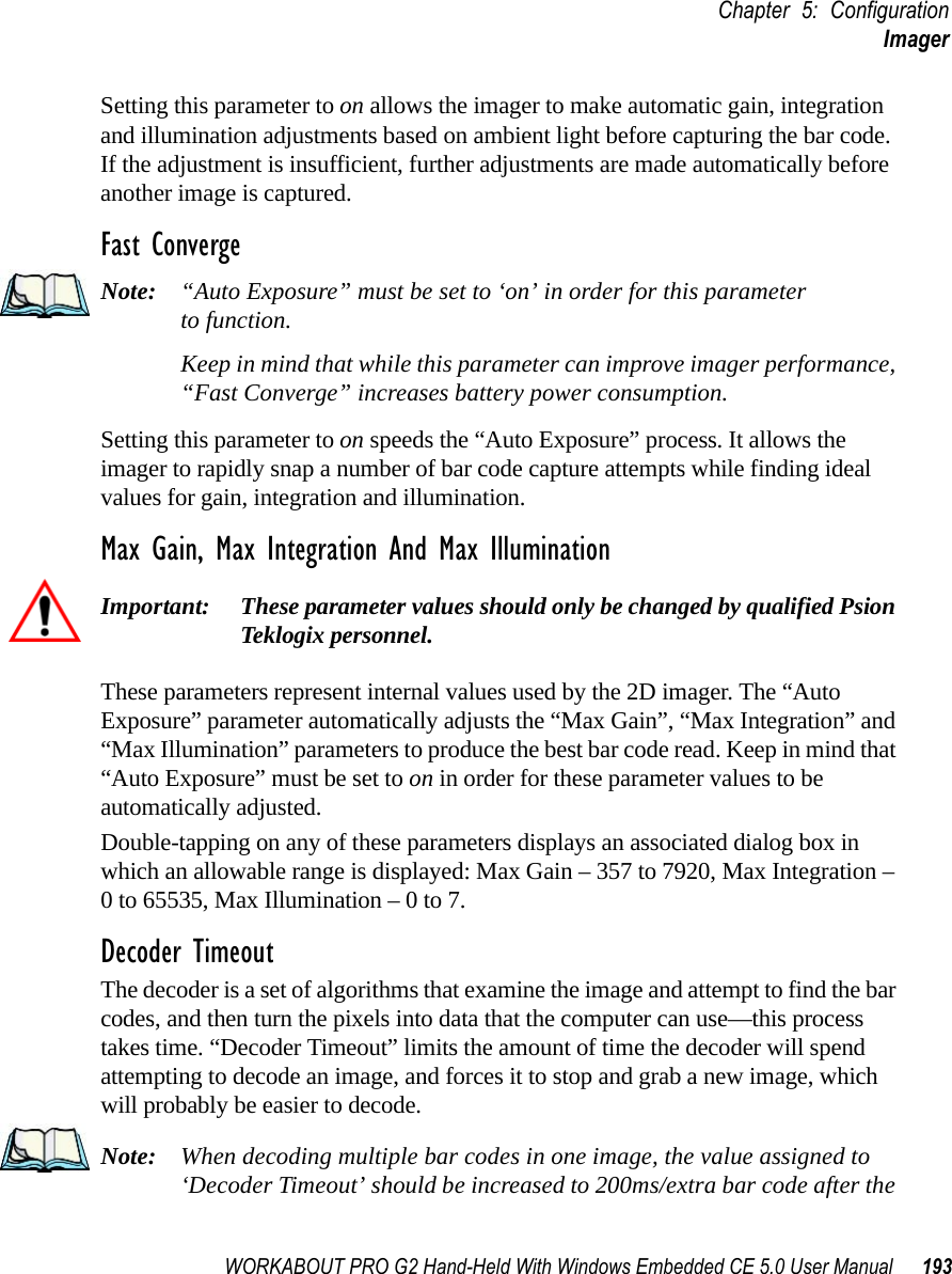
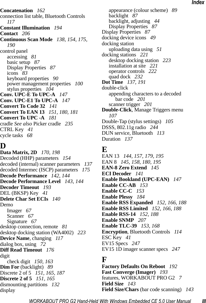
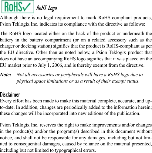
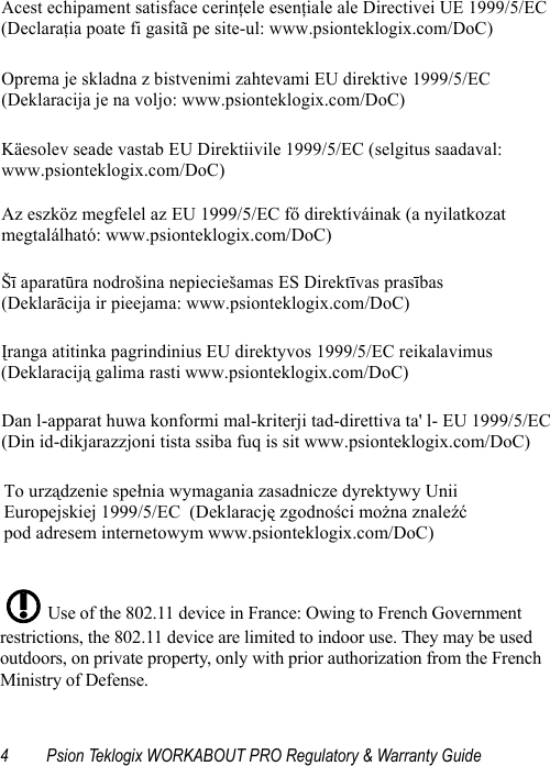
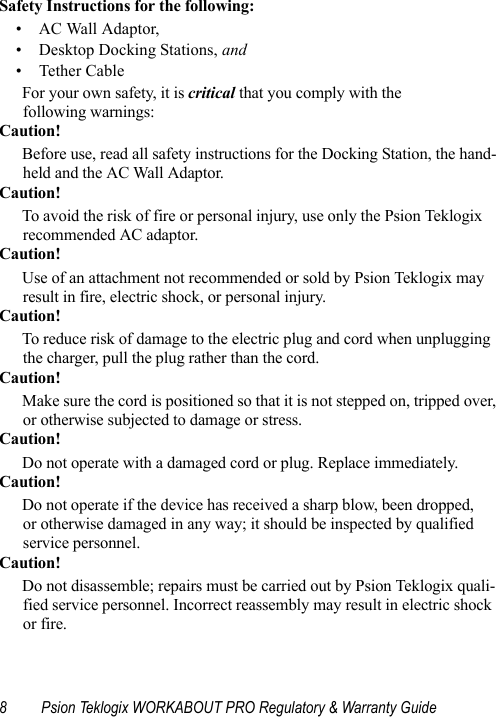
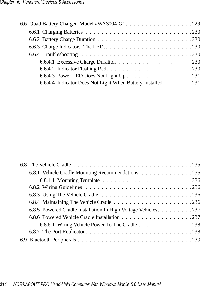
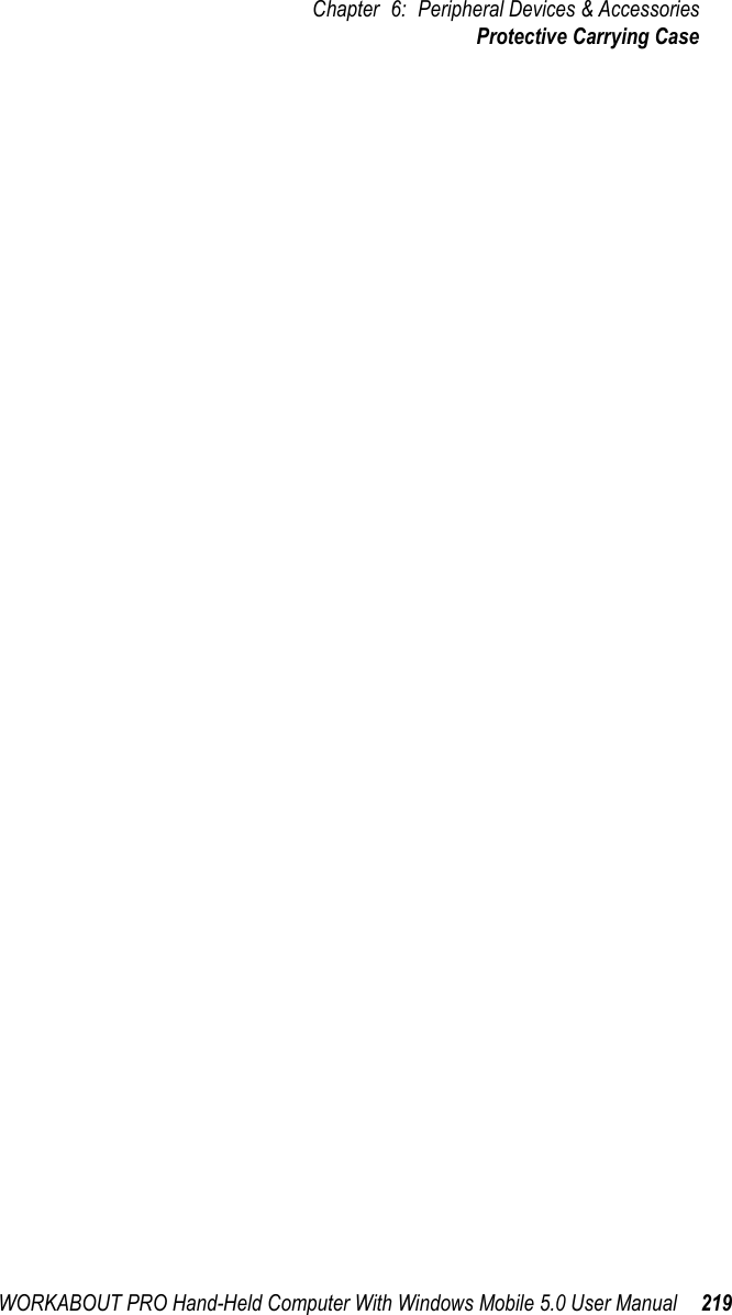
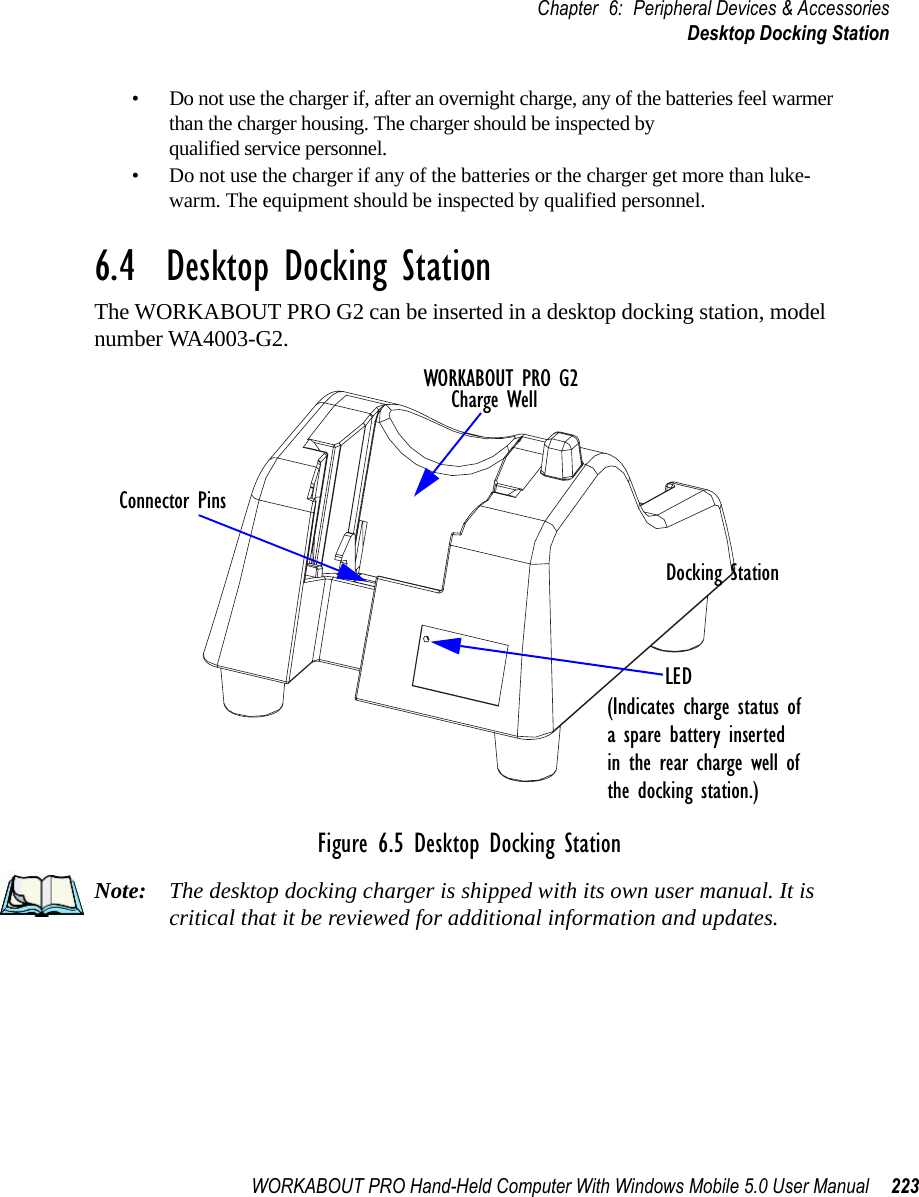
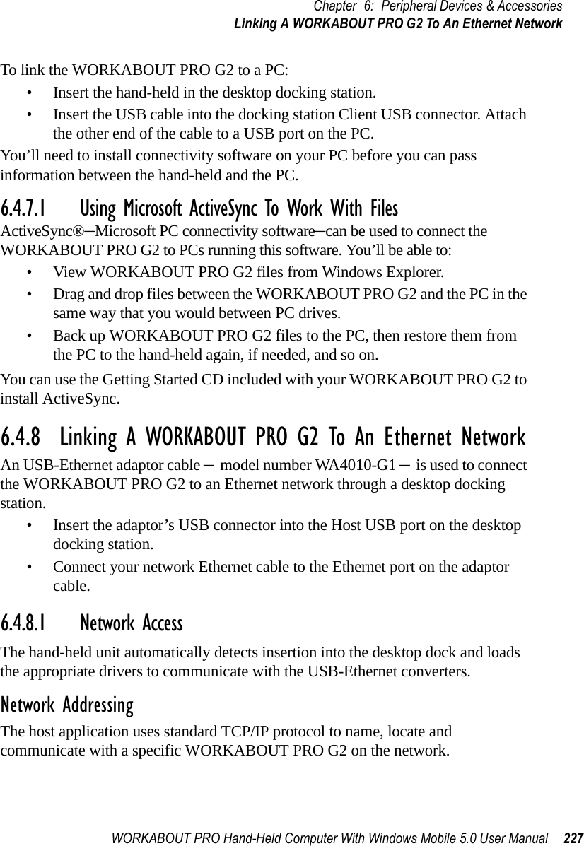
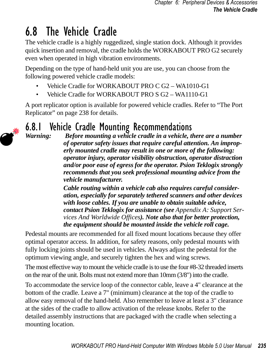
![Chapter 5: ConfigurationCommunities Tab208 WORKABOUT PRO G2 Hand-Held With Windows Embedded CE 5.0 User ManualNameThe value assigned here is the name assigned by the network administrator to the set of devices to which this managed node belongs.RightsThis menu allows you to specify access, that is, ‘Read-Only’ or ‘Read-Write’5.12.2.2 Modifying A Community SettingTo modify an existing community:• Highlight the community you want to alter.• Choose the Change button.A Modify Community dialog box is displayed, listing the community you highlighted.•Edit the Name and/or Rights, and press [ENTER] to save your changes.5.12.2.3 Removing An Existing CommunityTo remove an item:• Highlight the community you want to remove in the Communities tab and then choose the Remove button.A Delete Confirmation screen is displayed. • To remove a community, choose the Yes button, orIf you decide not to remove the community, choose the No button.](https://usermanual.wiki/Psion/7527RA2041.Users-Manual-Part-2/User-Guide-795589-Page-16.png)
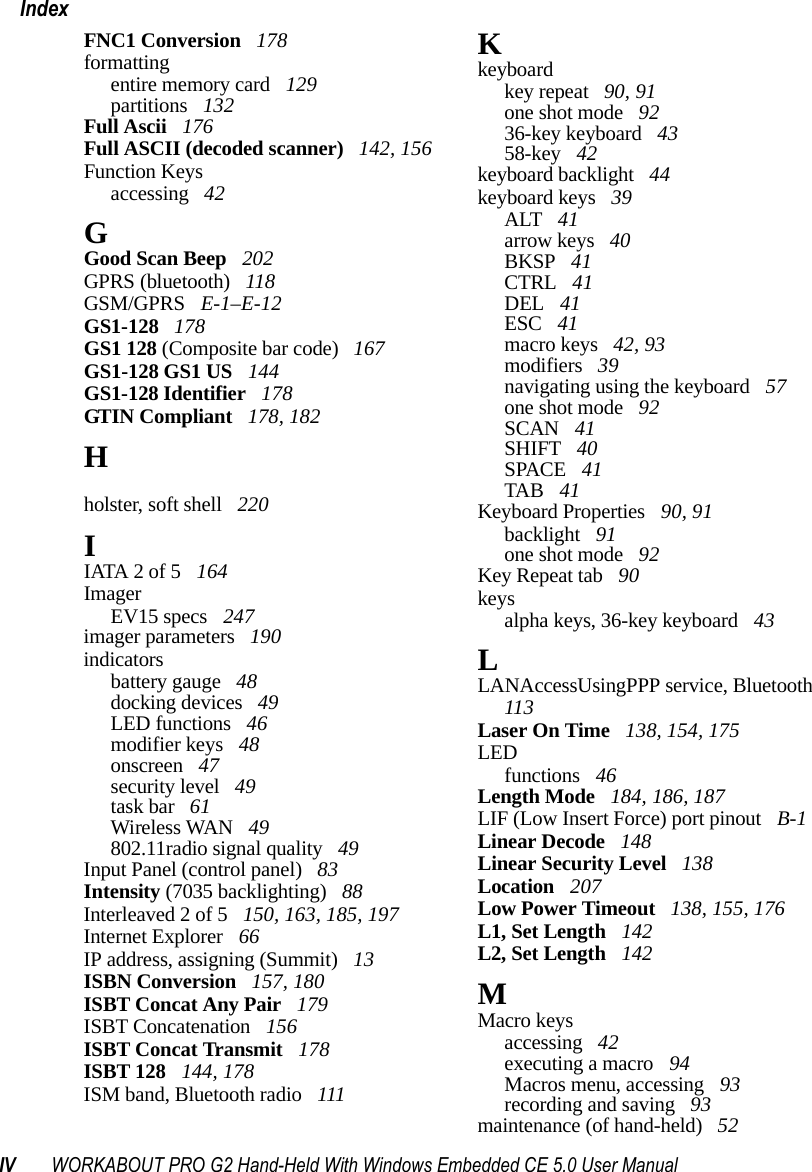
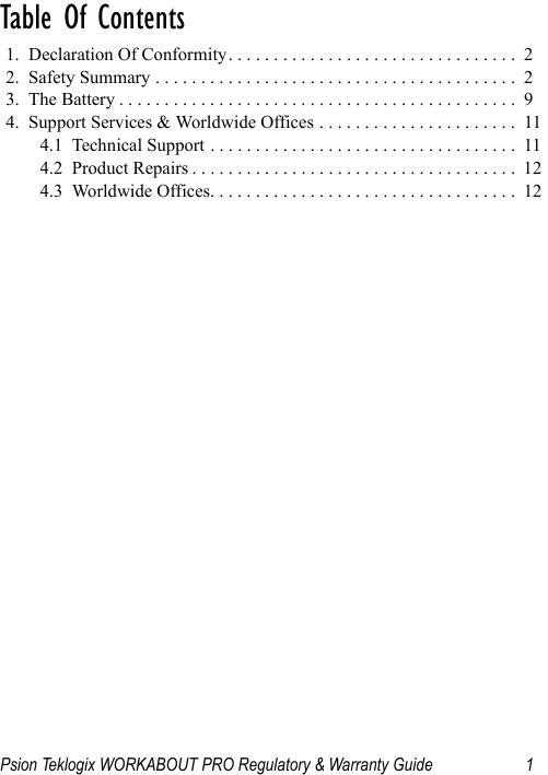
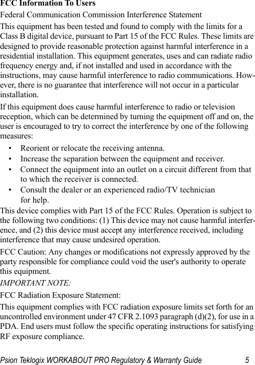
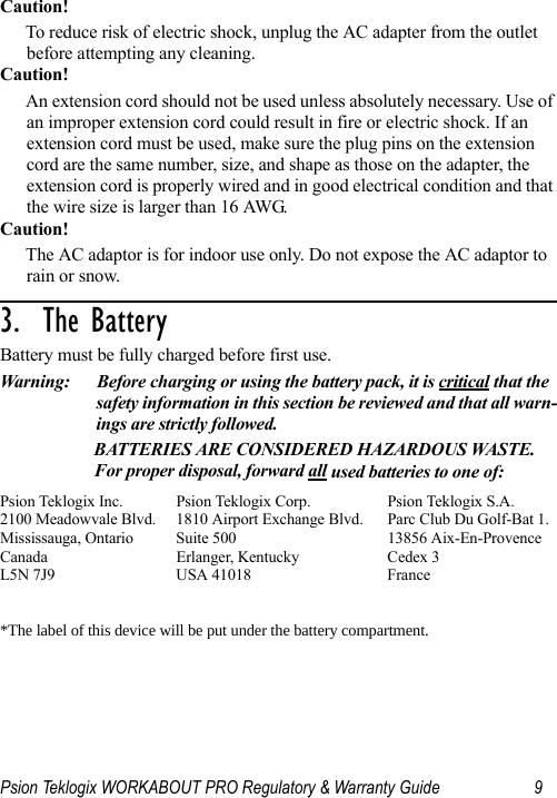
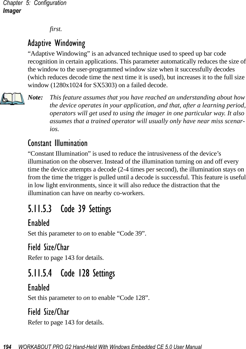
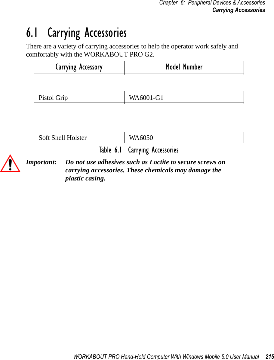
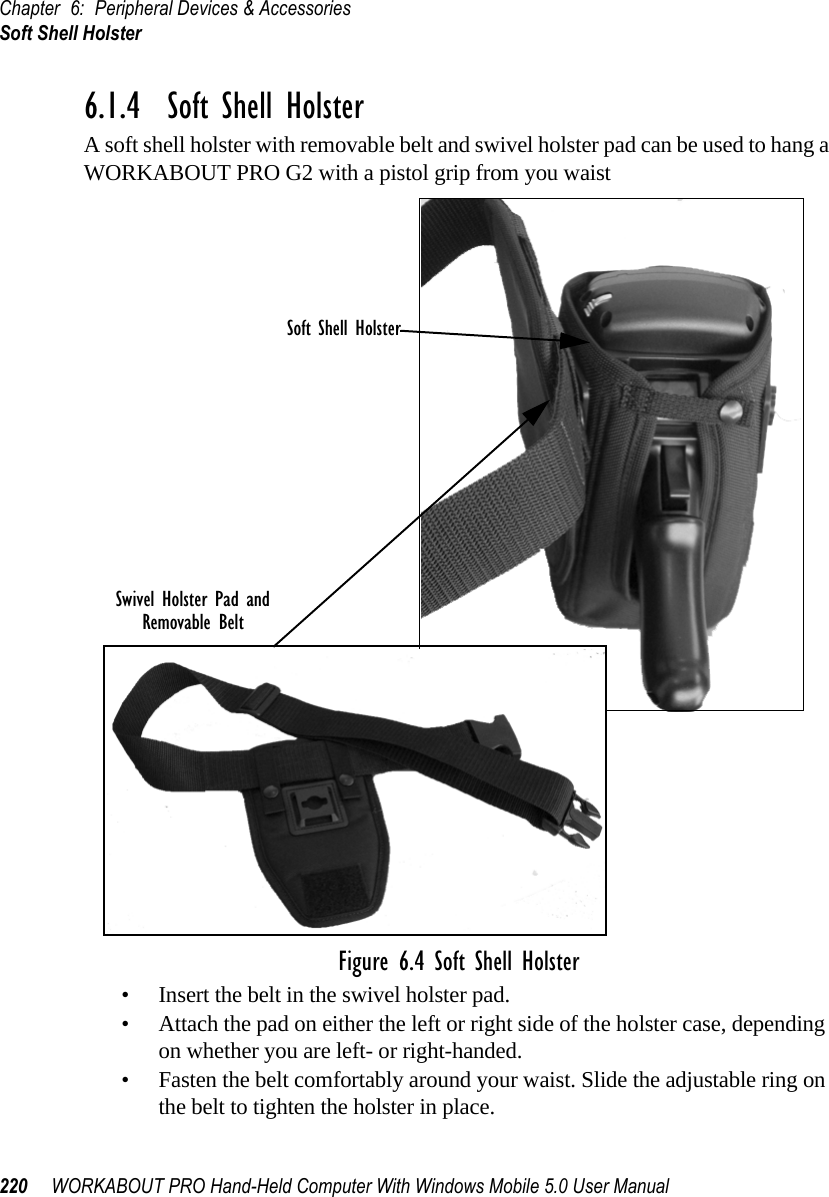
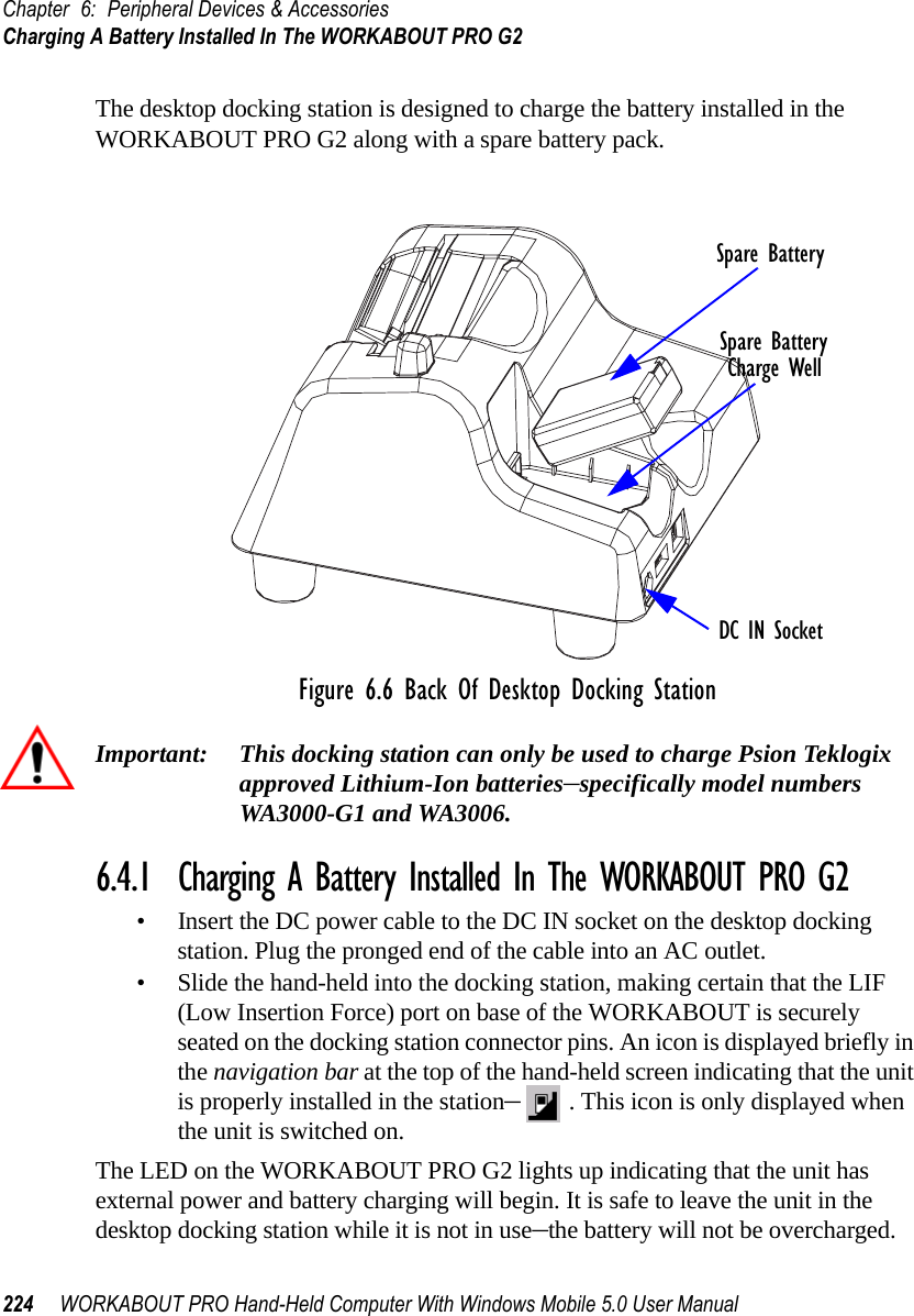
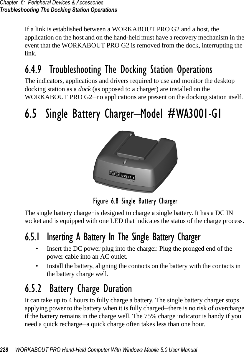
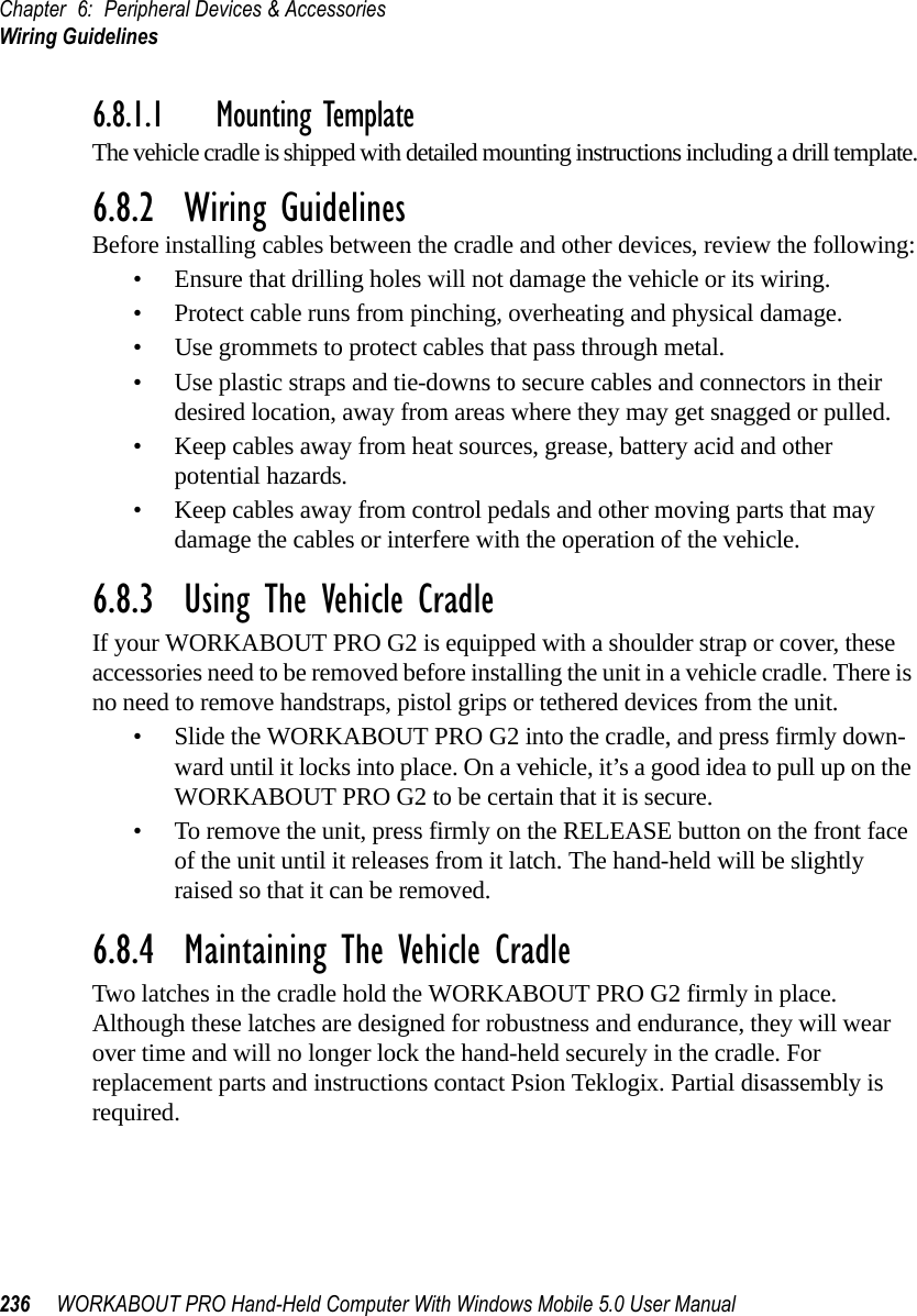
![WORKABOUT PRO G2 Hand-Held With Windows Embedded CE 5.0 User Manual 209Chapter 5: ConfigurationTrap Destination Tab5.12.3 Trap Destination TabA trap is an unsolicited report sent to SNMP Managers by the SNMP Agent running on the managed node. This option allows you to define where the report will be sent.5.12.3.1 Enabling Authentication TRAPSEnabling Enable Authentication TRAPS allows authorization traps to be sent when a failure is detected (e.g., an SNMP message received with a bad community name).5.12.3.2 Adding A DestinationTo add a new destination:• Choose the Add button.• Type a destination IP address in the text box provided, and press [ENTER].5.12.3.3 Changing A DestinationTo change an existing trap destination:• Highlight the destination you want to alter in the Trap Destination tab, and then choose the Change button.](https://usermanual.wiki/Psion/7527RA2041.Users-Manual-Part-2/User-Guide-795589-Page-17.png)
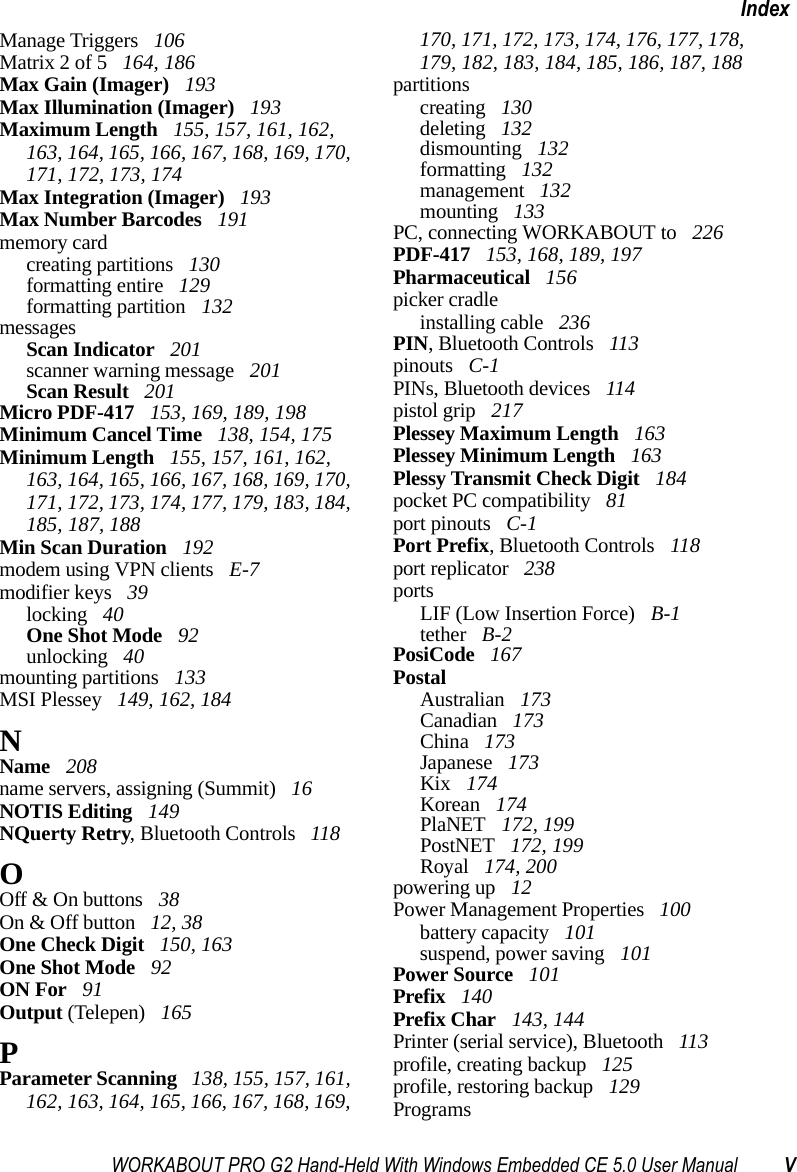
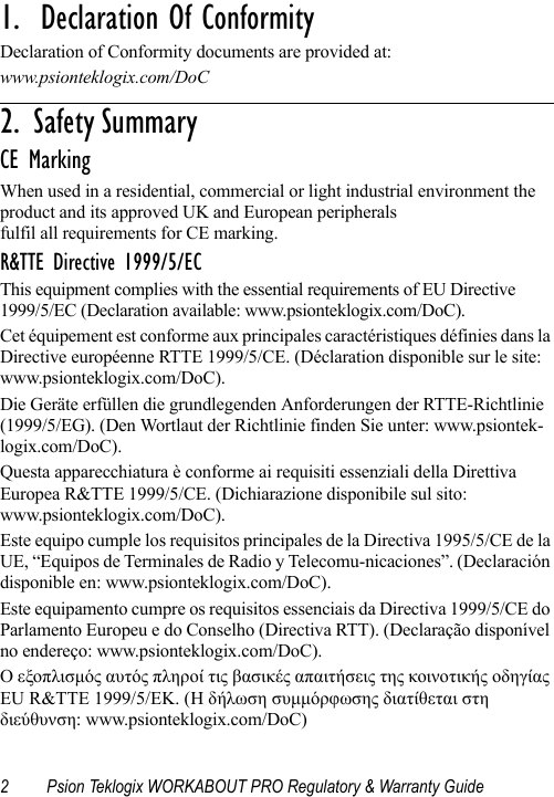
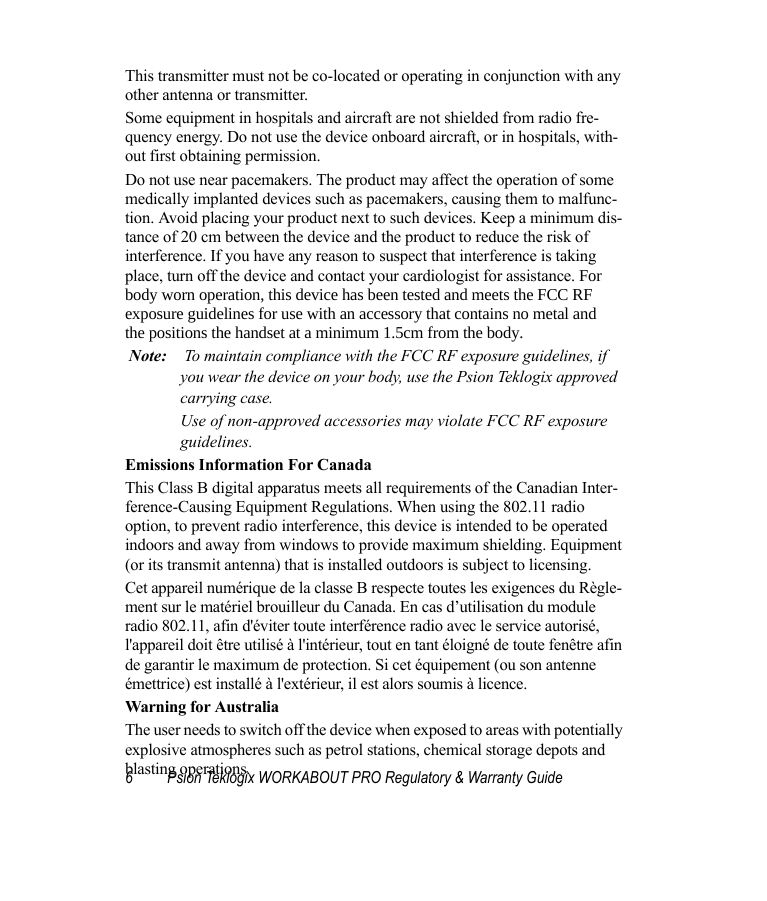
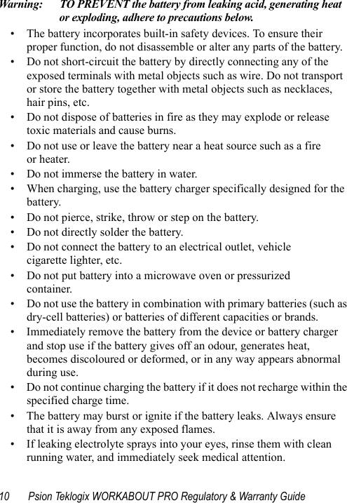
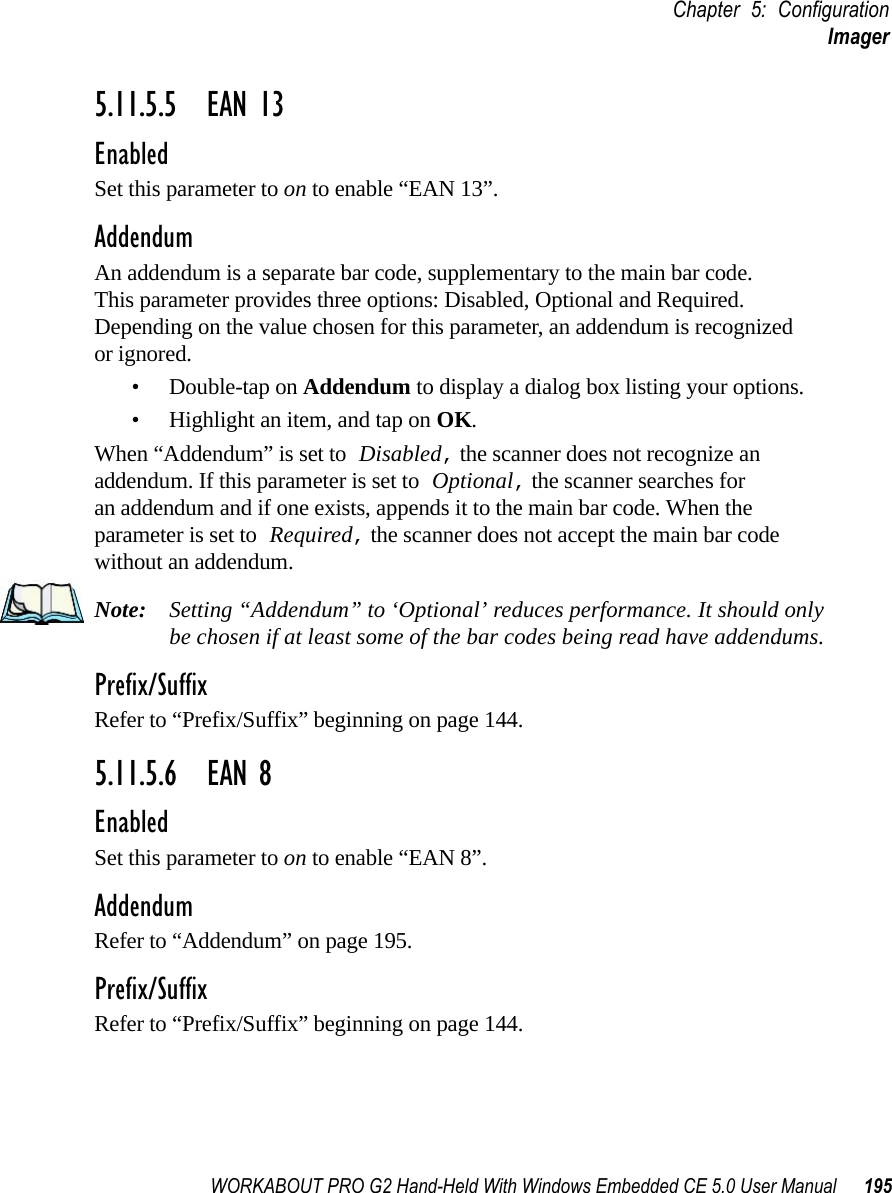
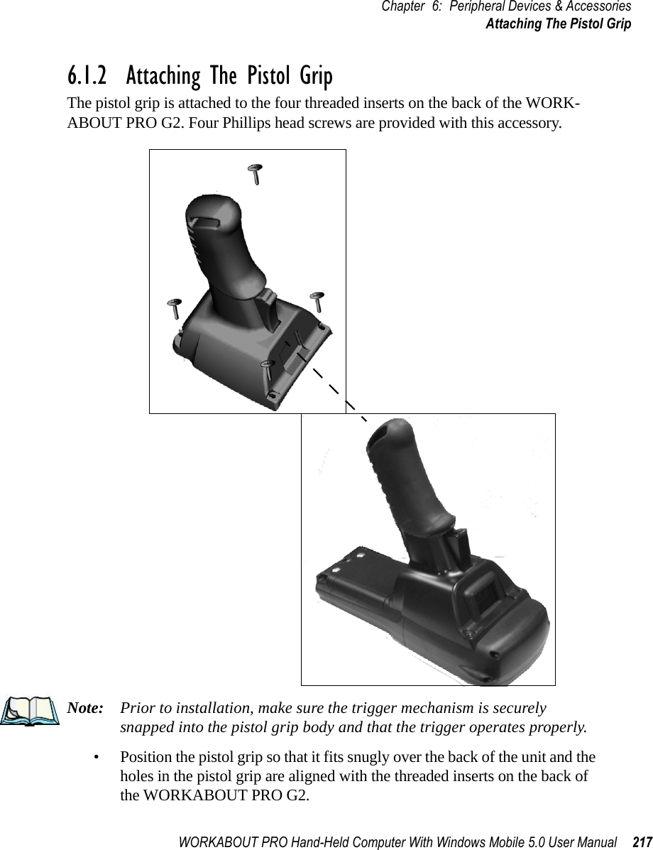
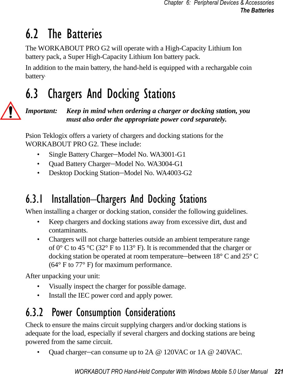
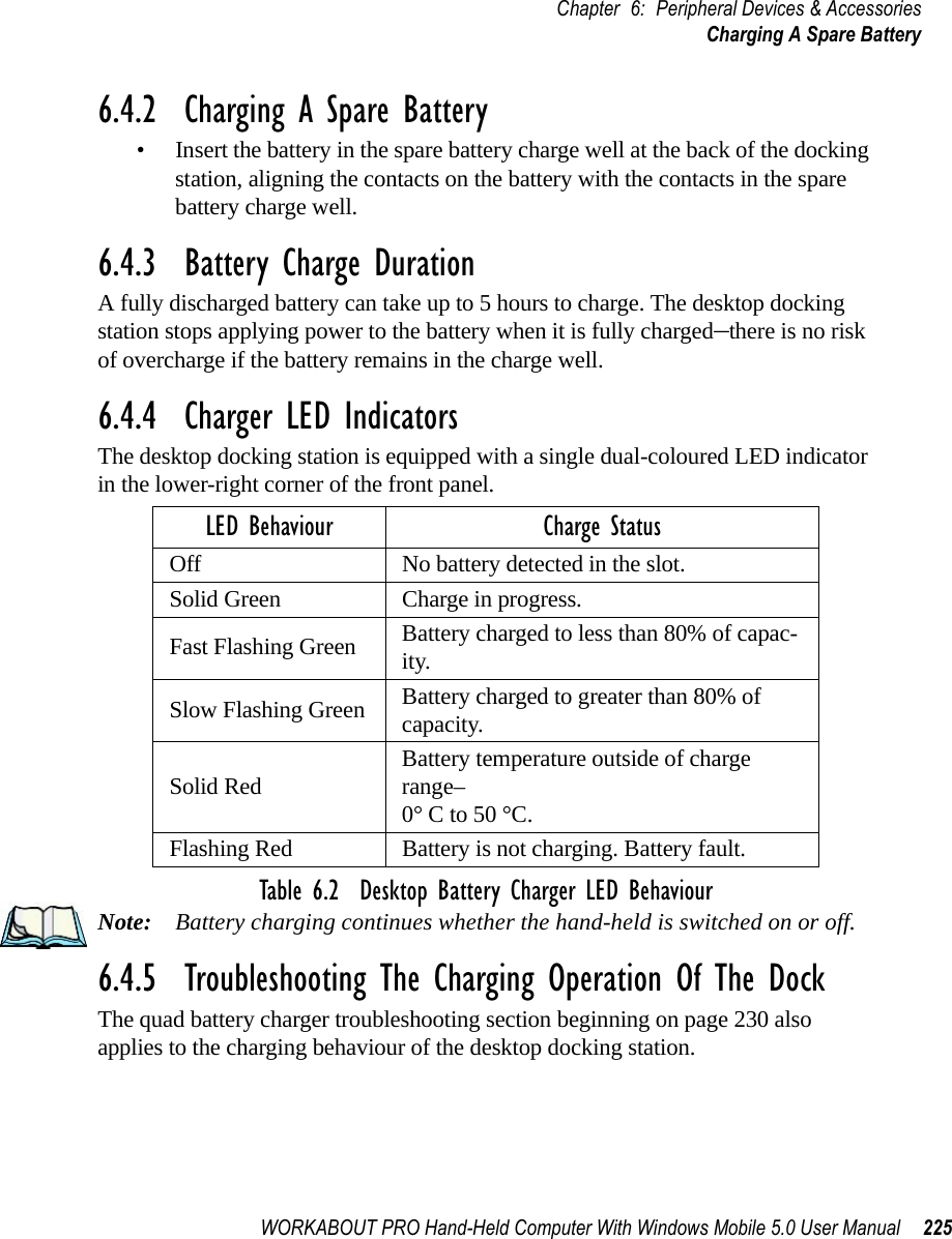
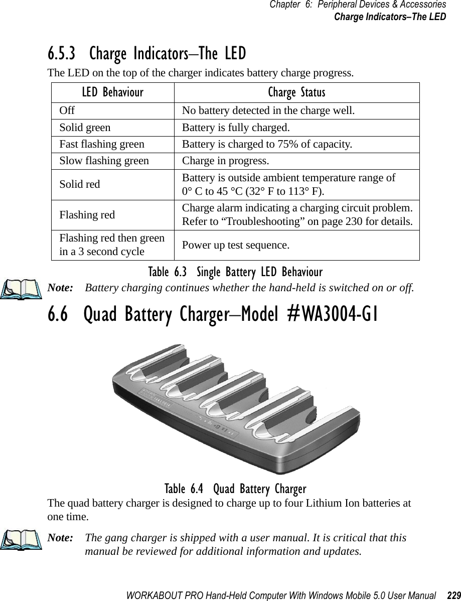
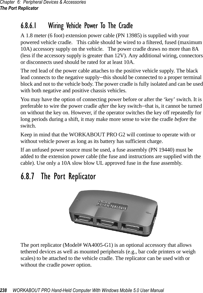
![Chapter 5: ConfigurationPermitted Hosts Tab210 WORKABOUT PRO G2 Hand-Held With Windows Embedded CE 5.0 User ManualA dialog box like the one displayed when you add a destination is displayed.• Make the changes to the destination, and press [ENTER] to save the changes.5.12.3.4 Removing A Trap DestinationTo remove a trap destination:•In the Trap Destination tab, highlight the destination you want to delete.• Choose the Remove button.A Delete Confirmation screen is displayed. • To remove a destination, choose the Yes button, orIf you decide not to remove the destination, choose the No button.5.12.4 Permitted Hosts TabFor security reasons, the Network Administrator may want to restrict SNMP-node access to a known sub-set of SNMP Managers. This tab lists the IP addresses of all the SNMP Managers which are allowed to monitor and manage this device. If no entries are listed, the device will accept SNMP queries from any host.](https://usermanual.wiki/Psion/7527RA2041.Users-Manual-Part-2/User-Guide-795589-Page-18.png)
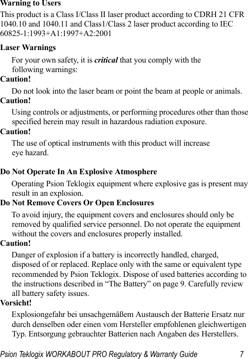
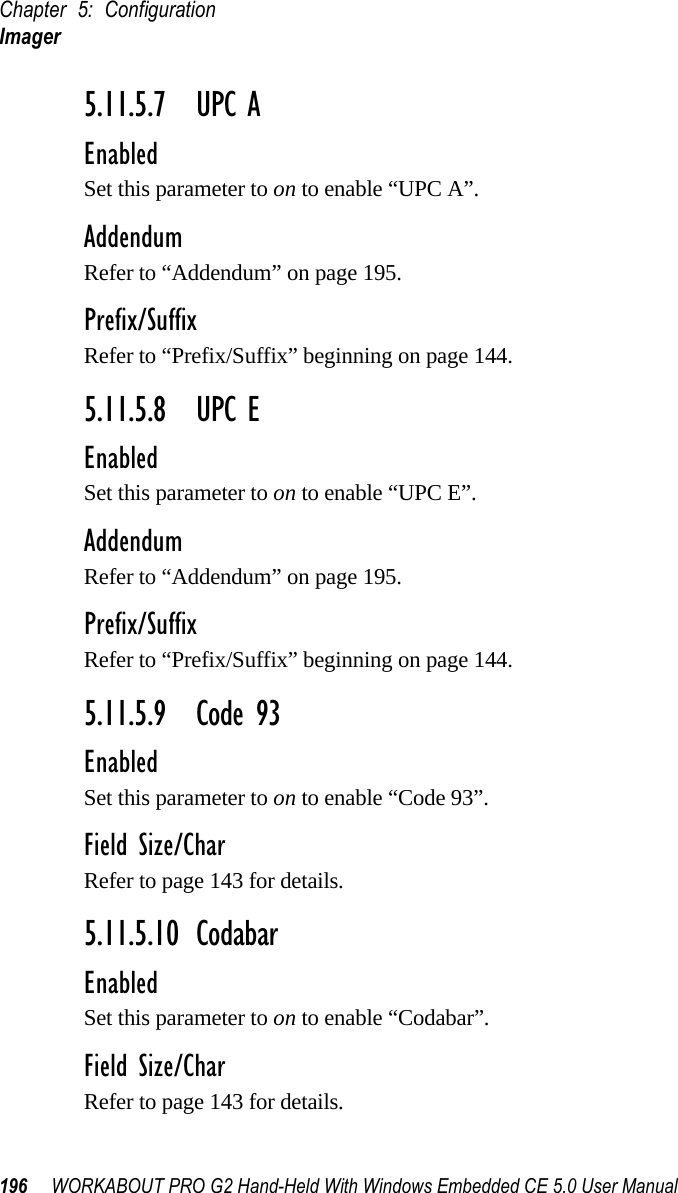
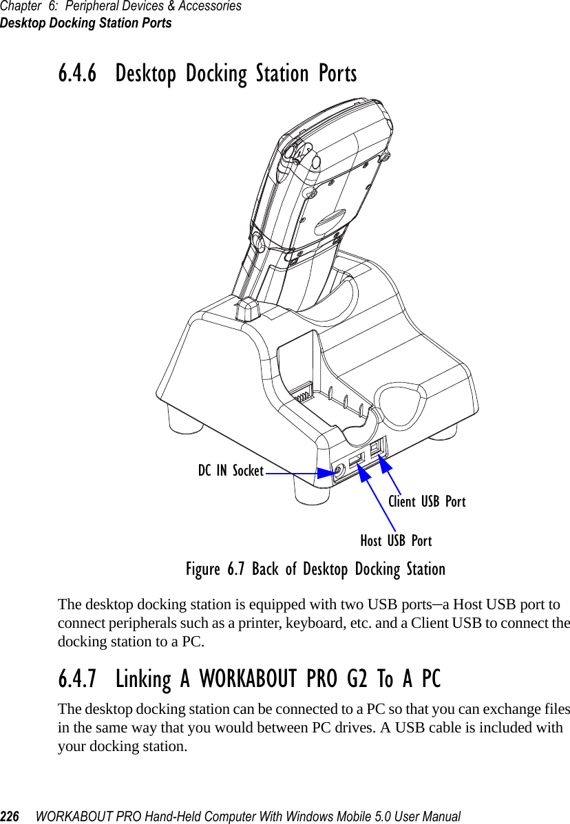
![WORKABOUT PRO G2 Hand-Held With Windows Embedded CE 5.0 User Manual 211Chapter 5: ConfigurationPermitted Hosts Tab5.12.4.1 Adding A HostTo add a new host:• Highlight the Add button, and press [ENTER].• Type a new host IP address in the text box provided, and press [ENTER].5.12.4.2 Changing A HostTo change an existing host IP address:• Highlight the IP address you want to alter in the Permitted Hosts tab, and then choose the Change button.A dialog box like the one displayed when you add a host is displayed.• Make the necessary changes, and press [ENTER].](https://usermanual.wiki/Psion/7527RA2041.Users-Manual-Part-2/User-Guide-795589-Page-19.png)

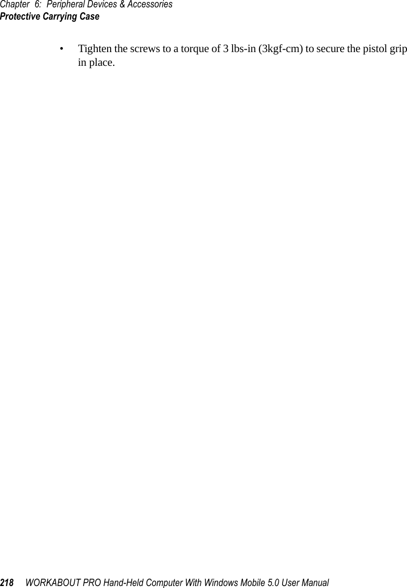
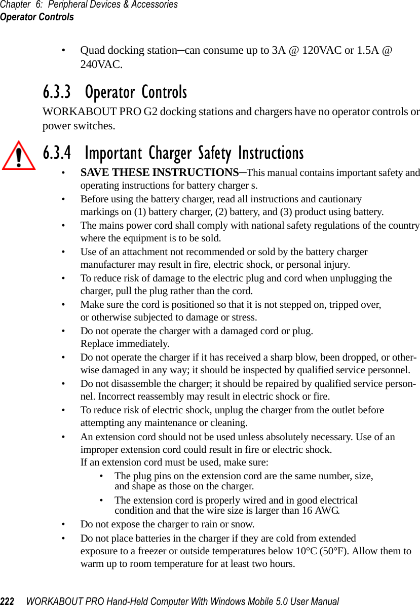
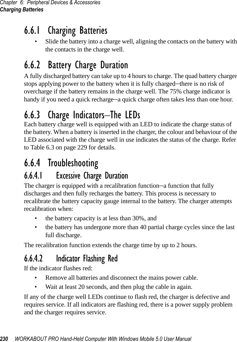

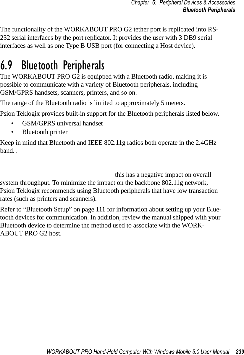
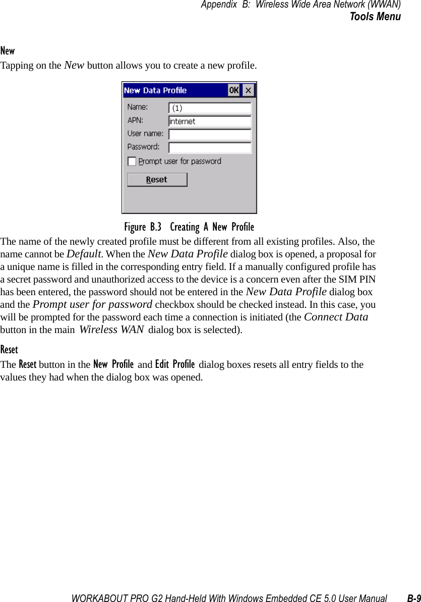
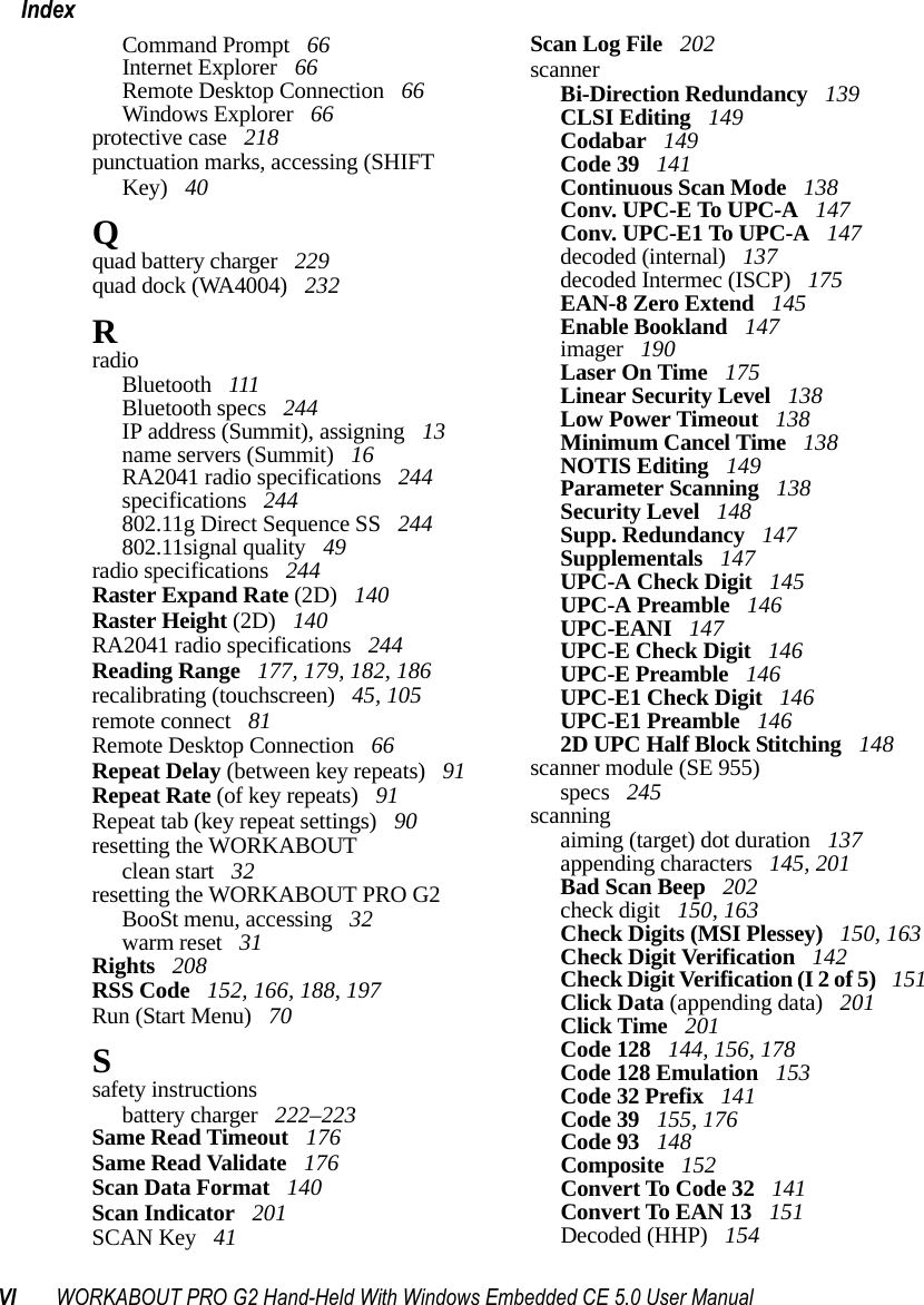
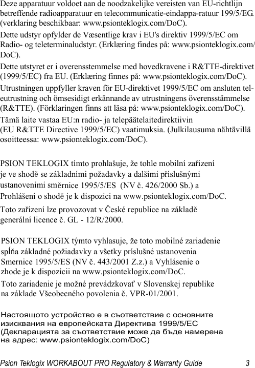
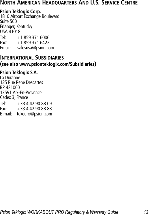
![Appendix B: Wireless Wide Area Network (WWAN)Advanced InformationB-4 WORKABOUT PRO G2 Hand-Held With Windows Embedded CE 5.0 User ManualB.1.3 Advanced InformationIn most cases, when a GSM/GPRS radio and SIM are installed in your computer, setup is automatic. Follow the steps outlined under the heading “Establishing A Connection” on page 2 to make a connection. The information in this section is for advanced setup purposes.Entering A PIN NumberIf a PIN is required, a PIN entry dialog box is displayed.• Type your PIN, and press [ENTER].Note: If you exceed the number of allowable attempts, a PUK entry window is brought to the foreground. You’ll need to enter a new PIN number.Once the correct PIN or PUK is entered or if none was required, the modem is instructed to perform a GSM network registration followed by a GPRS attach. The main Wireless WAN dialog box reflects the progress of the initialization.• Searching for modem• Initializing modem•SIM is ready• Searching for network• Registered on network• Searching for GPRS• Ready to connectIf the modem loses the connection to the GSM network, the following states are repeated: Searching for network, Registered on network, Searching for packet data, and Ready to con-nect. Error StatesThe following temporary error states (i.e., these states may disappear without interaction) may be displayed:• Emergency calls only.The modem has found a network but is not allowed to register (e.g. no roaming agreement between networks). The modem keeps searching for another network.](https://usermanual.wiki/Psion/7527RA2041.Users-Manual-Part-2/User-Guide-795589-Page-66.png)