Psion 7545LBWA Handheld Computer User Manual 7545 Hand Held Computer
Psion Inc Handheld Computer 7545 Hand Held Computer
Psion >
Contents
- 1. Regulatory Guide
- 2. Users Manual
Users Manual

7545
Hand-Held Computer
User Manual
-DQXDU\ , 20 P/N 8000190.A
ISO 9001 Certified
Quality Management System
Preliminary Draft 3

© Copyright 20 by Psion Teklogix Inc.
2100 Meadowvale Boulevard, Mississauga, Ontario, Canada L5N 7J9
http://www.psionteklogix.com
This document and the information it contains is the property of Psion Teklogix Inc., is
issued in strict confidence, and is not to be reproduced or copied, in whole or in part, except
for the sole purpose of promoting the sale of Psion Teklogix manufactured goods and ser-
vices. Furthermore, this document is not to be used as a basis for design, manufacture, or
sub-contract, or in any manner detrimental to the interests of Psion Teklogix Inc.
Disclaimer
Every effort has been made to make this material complete, accurate, and up-to-date. In ad-
dition, changes are periodically added to the information herein; these changes will be incor-
porated into new editions of the publication.
Psion Teklogix Inc. reserves the right to make improvements and/or changes in the prod-
uct(s) and/or the program(s) described in this document without notice, and shall not be re-
sponsible for any damages, including but not limited to consequential damages, caused by
reliance on the material presented, including but not limited to typographical errors.
Windows® and the Windows Logo are trademarks or registered trademarks of Microsoft
Corporation in the United States and/or other countries.
The Bluetooth word mark and logos are owned by Bluetooth SIG, Inc. and any use of such
marks by Psion Teklogix Inc. is under license.
All trademarks and trade names are the property of their respective holders.
Preliminary Draft 3
Return-To-Factory Warranty
Psion Teklogix Inc. provides a return to factory warranty on this product for a period of
twelve (12) months in accordance with the Statement of Limited Warranty and Limitation of
Liability provided at:
www.psionteklogix.com/warranty
The warranty on Psion Teklogix manufactured equipment does not extend to any product
that has been tampered with, altered, or repaired by any person other than an employee of an
authorized Psion Teklogix service organization. See Psion Teklogix terms and conditions of
sale for full details.
Service And Information
Psion Teklogix provides a complete range of product support services and information to its
customers worldwide. Services include technical support and product repairs. To locate your
local support services, please go to www.psionteklogix.com/service-and-support.htm
To access further information on current and discontinued products, please go to
https://teknet.psionteklogix.com and log in or tap on “Not Registered?”, depending on whether
you have previously registered for Teknet. A section of archived product information is
available online.
This Product, and its accessories, comply with the requirements of the Waste Electrical and
Electronic Equipment (WEEE) Directive 2002/96/EC. If your end-of-life Psion Teklogix
product or accessory carries a label as shown here, please contact your local country repre-
sentative for details on how to arrange recycling.
For a list of international subsidiaries, please go to:
www.psionteklogix.com/EnvironmentalCompliance
Important: Psion Teklogix warranties take effect on the date of shipment.
Waste Electrical and Electronic Equipment (WEEE) Directive 2002/96/EC
Preliminary Draft 3

Restriction On Hazardous Substances (RoHS) Directive 2002/95/EC
What is RoHS?
The European Union has mandated that high environmental standards be met in the design
and manufacture of electronic and electrical products sold in Europe, to reduce hazardous
substances from entering the environment. The “Restriction on Hazardous Substances Di-
rective (RoHS)” prescribes the maximum trace levels of lead, cadmium, mercury, hexava-
lent chromium, and flame retardants PBB and PBDE that may be contained in a product.
Only products meeting these high environmental standards may be “placed on the market”
in EU member states after July 1, 2006.
Although there is no legal requirement to mark RoHS-compliant products, Psion Teklogix
Inc. indicates its compliance with the directive as follows:
The RoHS logo located either on the back of the product or underneath the battery in the
battery compartment (or on a related accessory such as the charger or docking station) signi-
fies that the product is RoHS-compliant as per the EU directive. Other than as noted below,
a Psion Teklogix product that does not have an accompanying RoHS logo signifies that it
was placed on the EU market prior to July 1, 2006, and is thereby exempt from the directive.
RoHS Logo
Note: Not all accessories or peripherals will have a RoHS logo due to physical space
limitations or as a result of their exempt status.
Preliminary Draft 3

Psion Teklogix 7545 Hand-Held Computer User Manual i
TABLE OF CONTENTS
Chapter 1: Introduction
1.1 About This Manual......................................................................3
1.2 Text Conventions........................................................................4
1.3 7545 Features. ...........................................................................4
1.4 About The 7545 Hand-Held Computer. . . ................................................7
1.4.1 The 7545 Hand-Held Computer . ................................................8
1.4.2 Regulatory Labels..............................................................10
Chapter 2: Basic Checkout
2.1 Preparing The 7545 For Operation......................................................14
2.1.1 Equipment You Need To Get Started...........................................14
2.2 Powering Up The 7545 .................................................................14
2.2.1 Charging The Battery...........................................................14
2.2.2 Installing The Battery And Switching The Computer On .......................15
2.3 Attaching Carrying Accessories.........................................................16
2.3.1 Attaching The Hand Strap......................................................16
2.3.2 Attaching The Pistol Grip ......................................................18
2.4 Calibrating The Touchscreen............................................................19
2.5 Configuring Your Radio ................................................................19
2.6 Configuring An IEEE 802.11 Radio In The Unit ........................................19
2.6.1 Assigning An IP Address.......................................................25
2.6.2 Name Servers Tab..............................................................26
2.6.3 Advanced Features.............................................................27
2.6.3.1 Rearranging Preferred Networks .....................................27
2.6.3.2 Deleting A Preferred Network........................................27
2.6.3.3 Changing Network Properties........................................28
2.7 Summit Client Utility (SCU) For 802.11b/g Radio ......................................28
2.7.1 Assigning The IP Address......................................................28
2.7.2 Name Servers Tab..............................................................30
2.7.3 Using The SCU To Connect To The WLAN....................................31
2.7.3.1 SSID ................................................................32
2.7.3.2 EAP Type............................................................32
2.7.3.3 Encryption...........................................................32
Preliminary Draft 3
Contents
ii Psion Teklogix 7545 Hand-Held Computer User Manual
2.8 Checking The Scanner..................................................................33
2.9 Data Transfer Between The 7545 And A PC . . . ........................................34
2.9.1 Using Microsoft ActiveSync ...................................................34
2.9.2 Using Windows Vista..........................................................34
2.10 Resetting The 7545 . . ...................................................................35
Chapter 3: Getting To Know Your 7545
3.0.1 Battery Safety..................................................................39
3.0.2 Removing And Installing The Battery Pack.....................................39
3.0.3 Battery Chargers ...............................................................40
3.0.4 Monitoring The Battery And Maximizing Run Time............................41
3.0.4.1 Storing Batteries .....................................................42
3.1 Switching The Hand-Held On And Off .................................................43
3.2 The Keyboard ..........................................................................43
3.2.1 Modifier Keys..................................................................44
3.2.1.1 Activating Modifier Keys............................................44
3.2.1.2 Locking Modifier Keys ..............................................45
3.2.2 The Keys.......................................................................45
3.2.3 Function Keys, Softkeys And Macro Keys......................................46
3.2.3.1 Function Keys .......................................................46
3.2.3.2 Macro Keys..........................................................47
3.2.4 Alphanumeric Keyboard: 58-Key...............................................47
........................................
3.2.6 The Keypad Backlight..........................................................50
3.3 The Display.............................................................................50
3.3.1 Adjusting The Display Backlight...............................................50
3.3.2 Adjusting The Contrast.........................................................51
3.3.3 Calibrating The Touchscreen...................................................51
3.4 7545 Indicators .........................................................................52
3.4.1 LEDs...........................................................................52
3.4.1.1 Charge LED .........................................................53
3.4.1.2 Radio Traffic LED ...................................................53
3.4.1.3 Scan LED............................................................54
3.4.1.4 User Application LED ...............................................54
3.4.2 Onscreen Indicators ............................................................54
3.4.3 Audio Indicators ...............................................................57
3.4.3.1 Adjusting The Beeper Volume .......................................57
3.5 Internal Scanners .......................................................................58
3.5.1 Scanning Techniques...........................................................59
Preliminary Draft 3
Contents
Psion Teklogix 7545 Hand-Held Computer User Manual iii
3.5.2 Scan LED Indicators ...........................................................59
3.5.3 Troubleshooting ................................................................60
3.5.4 Operating One Dimensional (1D) Internal Laser Scanners......................60
3.5.5 Operating Internal PDF Laser Scanners.........................................60
3.5.6 Operating Internal Two Dimensional (2D) Imager Scanners ....................61
3.5.7 Operating RFID/Scanner Modules..............................................62
3.6 Connecting And Disconnecting Tethered Peripherals....................................62
3.7 Monitoring The Network Connection...................................................63
3.8 Uploading Data In A Docking Station...................................................64
3.9 General Maintenance ...................................................................64
3.9.1 Caring For The Touchscreen ...................................................64
3.9.2 Cleaning The 7545 .............................................................64
Chapter 4: Windows Embedded CE 5.0
4.1 Navigating In Windows CE And Applications ..........................................69
4.1.1 Navigating Using A Touchscreen And Stylus...................................69
4.1.2 Navigating Using The Keyboard ...............................................69
4.2 Working With Files, Folders And Programs.............................................71
4.3 The Startup Desktop....................................................................71
4.3.1 The Desktop Icons .............................................................72
4.3.2 The Taskbar....................................................................73
4.3.2.1 Using The Taskbar...................................................74
4.3.2.2 Customizing The Taskbar ............................................74
4.4 The Start Menu .........................................................................75
4.4.1 The Desktop....................................................................76
4.4.2 Security Settings ...............................................................76
4.4.3 Programs.......................................................................78
4.4.4 Shortcuts.......................................................................79
4.4.5 Settings ........................................................................81
4.4.6 Run ............................................................................82
4.4.7 Shutdown ......................................................................82
4.5 Using A Dialog Box....................................................................83
Chapter 5: Configuration
5.1 Remote Connect .......................................................................89
5.2 The TekTerm Application...............................................................89
5.3 Pocket PC Compatibility................................................................89
5.4 The Control Panel ......................................................................89
Preliminary Draft 3
Contents
iv Psion Teklogix 7545 Hand-Held Computer User Manual
5.5 Control Panel Icons.....................................................................90
5.6 Control Panel Applications: Basic Setup................................................94
5.6.1 App Launch Keys..............................................................94
5.6.2 Certificates.....................................................................96
5.6.3 Display Properties..............................................................97
5.6.3.1 Background .........................................................98
5.6.3.2 Appearance..........................................................98
5.6.3.3 Backlight............................................................99
5.6.3.4 Contrast............................................................100
5.6.4 Input Panel....................................................................101
5.6.5 Keyboard Properties..........................................................102
5.6.5.1 Key Repeat .........................................................103
5.6.5.2 Keyboard Backlight.................................................104
5.6.5.3 Keyboard One Shot Modes..........................................105
5.6.5.4 Keyboard Macro Keys ..............................................106
5.6.5.5 Unicode Mapping...................................................108
5.6.5.6 Scancode Remapping ...............................................109
5.6.5.7 Lock Sequence......................................................112
5.6.6 Manage Triggers ..............................................................113
5.6.6.1 Trigger Mappings...................................................114
5.6.6.2 Add And Edit Trigger Mapping .....................................115
5.6.7 Power Management Properties ................................................117
5.6.7.1 Battery Capacity ....................................................117
5.6.7.2 Power Saving Suspend..............................................118
5.6.7.3 Suspend Threshold And Estimated Battery Backup..................119
5.6.7.4 Calibrate............................................................120
5.6.7.5 Advanced...........................................................121
5.6.7.6 Devices.............................................................122
5.6.7.7 Built In Devices.....................................................122
5.6.8 Stylus Properties ..............................................................122
5.6.8.1 Double-Tap .........................................................123
5.6.8.2 Calibration..........................................................123
5.6.8.3 Touch...............................................................124
5.6.9 Volume And Sounds Properties ...............................................124
5.6.9.1 Volume Adjustments................................................124
5.6.9.2 Sound Adjustments . . . ..............................................124
5.7 Bluetooth Setup........................................................................124
5.7.1 Devices .......................................................................125
5.7.2 Headset .......................................................................129
5.7.3 Servers........................................................................130
Preliminary Draft 3
Contents
Psion Teklogix 7545 Hand-Held Computer User Manual v
5.7.4 Outgoing......................................................................131
5.7.5 Active Conn. .................................................................132
5.7.6 Properties .....................................................................133
5.7.7 Search For ....................................................................134
5.8 Error Reporting........................................................................134
5.9 IPv6 Support...........................................................................134
5.10 Scanner Settings.......................................................................135
5.10.1 Bar Codes.....................................................................136
5.10.1.1 Scanner.............................................................136
5.10.1.2 Restoring Default Settings...........................................137
5.10.2 Options........................................................................138
5.10.2.1 Double Click Parameters............................................138
5.10.2.2 Display Parameters..................................................139
5.10.3 Translations ..................................................................140
5.10.3.1 Case Rules..........................................................142
5.10.4 Ports ..........................................................................143
5.10.4.1 Console Port.....................................................144
5.11 SNMP (Simple Network Management Protocol) Setup.................................148
5.11.1 Contact........................................................................148
5.11.2 Communities..................................................................149
5.11.2.1 Adding A Community ..............................................150
5.11.2.2 Modifying A Community Setting ...................................150
5.11.2.3 Removing An Existing Community .................................150
5.11.3 Trap Destination...............................................................151
5.11.3.1 Enabling Authentication TRAPS....................................151
5.11.3.2 Adding A Destination...............................................151
5.11.3.3 Changing A Destination.............................................152
5.11.3.4 Removing A Trap Destination.......................................152
5.11.4 Permitted Hosts ...............................................................153
5.11.4.1 Adding A Host......................................................153
5.11.4.2 Changing A Host....................................................153
5.12 The Storage Manager..................................................................154
5.12.1 Formatting A Memory Card...................................................154
5.12.2 Creating Partitions.............................................................155
5.12.3 Partition Management.........................................................156
5.13 Teklogix Error Handling Service.......................................................158
5.13.1 ErrorLogInfo..................................................................158
Preliminary Draft 3
Contents
vi Psion Teklogix 7545 Hand-Held Computer User Manual
5.13.2 NetLog........................................................................159
5.14 Teklogix Imagers ......................................................................160
5.15 Total Recall. . . .........................................................................161
5.15.1 Creating A Backup Profile.....................................................161
5.15.2 Restoring A Profile............................................................165
5.16 TweakIT Settings......................................................................166
5.16.1 Advanced .....................................................................166
5.16.1.1 Advanced Interface And Network...................................166
5.16.1.2 Advanced Services Settings.........................................167
5.16.1.3 Advanced Intermediate Driver ......................................168
5.16.1.4 Radio Features......................................................169
5.16.2 User...........................................................................170
5.16.2.1 Internet Explorer Settings ...........................................170
5.16.2.2 User Display Settings ...............................................170
5.16.2.3 User System Settings................................................171
5.16.3 Registry Editor................................................................172
Chapter 6: Peripheral Devices & Accessories
6.1 External Bar Code Readers ............................................................175
6.1.1 PowerScan® Standard, LR and XLR Bar Code Scanners ......................175
6.1.2 Entering Data With The Bar Code Reader.....................................175
6.3 Batteries...............................................................................176
6.4 Battery Charging.......................................................................176
6.4.1 Battery Gas Gauge Calibration ................................................176
6.5 Gang Charger..........................................................................177
6.5.1 Installation ....................................................................177
6.5.2 Operator Controls .............................................................178
6.5.3 Charge Indicators..............................................................178
6.5.4 Charging Batteries.............................................................179
6.5.5 Troubleshooting...............................................................179
6.5.5.1 Excessive Charge Duration..........................................179
6.5.5.2 Improper Battery Storage ...........................................179
6.5.5.3 Indicator Flashing Red..............................................180
6.5.5.4 Power LED Does Not Light Up.....................................180
6.5.5.5 Indicator Does Not Light When Battery Installed....................180
6.6 Combo Charger........................................................................180
6.6.1 Installation ....................................................................180
6.6.2 Operator Controls .............................................................181
Preliminary Draft 3
Contents
Psion Teklogix 7545 Hand-Held Computer User Manual vii
6.6.3 Using the Combo Charger With The 7545 .....................................181
6.6.4 Charging The Spare Battery...................................................181
6.6.5 Charge Indicators..............................................................182
6.6.6 Troubleshooting ...............................................................182
6.7 Combo Dock ..........................................................................182
6.7.1 Installation ....................................................................182
6.7.2 Using The Combo Dock.......................................................182
6.7.3 Network Access...............................................................183
6.7.4 Troubleshooting ...............................................................183
6.8 Quad Dock ............................................................................183
6.8.1 Installation ....................................................................183
6.8.2 Indicators And Controls.......................................................184
6.8.3 Using The Quad Dock.........................................................184
6.8.4 Network Access...............................................................184
6.8.4.1 Network Addressing ................................................185
6.8.5 Battery Charging..............................................................185
6.8.6 Troubleshooting ...............................................................185
6.8.6.1 Network Link Unsuccessful . . .......................................185
6.8.6.2 7545 LED Does Not Light When Docked . ..........................185
6.9 Portable Docking Module (PDM)......................................................186
6.10 Bluetooth Peripherals ..................................................................188
6.11 The 7545 Picker Cradle ................................................................189
6.11.1 Picker Cradle Mounting Recommendations....................................189
6.11.1.1 Mounting Template .................................................190
6.11.2 Wiring Guidelines.............................................................190
6.11.3 Using The Picker Cradle ......................................................190
6.11.4 Maintaining The Picker Cradle................................................190
6.11.5 Powered Cradle Installation In High Voltage Vehicles.........................191
6.11.5.1 Extreme Wet Environments .........................................191
6.11.6 Powered Cradle Installation ...................................................192
6.11.7 Wiring Vehicle Power To The Cradle .........................................193
6.11.8 The Port Replicator............................................................193
6.12 Tether Adaptor Cables.................................................................194
Chapter 7: Specifications
7.1 7545 Hand-Held Computer Specifications .............................................197
7.1.1 Hardware......................................................................197
7.1.2 Software ......................................................................199
7.1.3 Approvals.....................................................................200
Preliminary Draft 3
Contents
viii Psion Teklogix 7545 Hand-Held Computer User Manual
7.2 Murata Radio Specifications...........................................................200
7.3 Internal Scanner Port ..................................................................201
7.6 Internal Scanners .... ........ .........................................................202
7.6.1 SE1224 HP - High Performance.......................................202
7.6.1.1 SE1224HP Decode Zones.........................................203
7.7HU3000 - 1900 mAh Lithium-ion Battery Pack. .......................................204
Appendix A: Port Pinouts
A1Docking Station Connector ........................................................... A-1
A.2Battery Contacts...................................................................... A-2
Appendix B: SCU For 802.11b/g Radio
B.1 SCU Tabs..............................................................................B-3
B.1.1 Main ..........................................................................B-3
B.1.2 Profile.........................................................................B-4
B.1.3 Status .........................................................................B-9
Preliminary Draft 3
Contents
Psion Teklogix 7545 Hand-Held Computer User Manual ix
B.1.4 Diags .........................................................................B-9
B.1.5 Global ...................................................................... B-10
Appendix C: Bar Code Settings
C.1 Bar Code Settings......................................................................C-5
C.1.1 Scanner Options...............................................................C-5
C.1.2 Restoring Default Settings.....................................................C-6
C.2 Decoded (Internal) Scanners...........................................................C-7
C.2.1 Options........................................................................C-7
C.2.2 Decoded (Internal) Advanced Options ........................................C-8
C.2.3 Decoded (Internal) 2D Scanning Options.................................... C-10
C.2.4 Decoded (Internal) Data Options ............................................ C-11
C.2.5 Code 39..................................................................... C-12
C.2.6 Code 128.................................................................... C-15
C.2.7 EAN 13..................................................................... C-16
C.2.8 EAN 8 ...................................................................... C-16
C.2.9 UPC A...................................................................... C-16
C.2.10 UPC E ...................................................................... C-17
C.2.11 UPC/EAN Shared Settings .................................................. C-18
C.2.12 Code 93..................................................................... C-19
C.2.13 Codabar..................................................................... C-19
C.2.14 MSI Plessey................................................................. C-20
C.2.15 Interleaved 2 of 5............................................................ C-21
C.2.16 Discrete 2 of 5............................................................... C-22
C.2.17 RSS Code (Reduced Space Symbology) ..................................... C-22
C.2.18 Composite .................................................................. C-23
C.2.19 PDF-417 .................................................................... C-24
C.2.20 Micro PDF-417 ............................................................. C-24
C.3 Decoded (Intermec ISCP)............................................................ C-25
C.3.1 Decoded (ISCP) Options .................................................... C-25
C.3.2 Decoded (ISCP) Advanced Options ......................................... C-25
C.3.3 Code 39..................................................................... C-26
C.3.4 Code 128.................................................................... C-28
C.3.5 EAN 13 ..................................................................... C-29
C.3.6 EAN 8 ...................................................................... C-30
C.3.7 UPC A ...................................................................... C-30
C.3.8 UPC E Settings.............................................................. C-31
C.3.9 UPC/EAN Shared Settings .................................................. C-31
C.3.10 Code 93..................................................................... C-32
Preliminary Draft 3
Contents
xPsion Teklogix 7545 Hand-Held Computer User Manual
C.3.11 Codabar..................................................................... C-33
C.3.12 MSI Plessey................................................................. C-34
C.3.13 Code 11..................................................................... C-35
C.3.14 Interleaved 2 of 5............................................................ C-35
C.3.15 Matrix 2 of 5 ................................................................ C-36
C.3.16 Discrete 2 of 5............................................................... C-37
C.3.17 Telepen ..................................................................... C-37
C.3.18 RSS Code (Reduced Space Symbology) ..................................... C-38
C.3.19 Composite.................................................................. C-39
C.3.20 TLC-39..................................................................... C-39
C.3.21 PDF-417 .................................................................... C-40
C.3.22 Micro PDF-417 ............................................................. C-40
C.3.23 Codablock................................................................... C-41
C.4 Imager............................................................................... C-41
C.4.1 Imager Options.............................................................. C-41
C.4.2 Imager Advanced Options................................................... C-43
C.4.3 Code 39 .................................................................... C-45
C.4.4 Code 128 ................................................................... C-46
C.4.5 EAN 13..................................................................... C-46
C.4.6 EAN 8 ...................................................................... C-47
C.4.7 UPC A...................................................................... C-47
C.4.8 UPC E ...................................................................... C-47
C.4.9 Code 93..................................................................... C-48
C.4.10 Codabar..................................................................... C-48
C.4.11 Interleaved 2 of 5........................................................... C-48
C.4.12 RSS Code (Reduced Space Symbology) .................................... C-49
C.4.13 Composite................................................................... C-49
C.4.14 PDF-417.................................................................... C-49
C.4.15 Micro PDF-417............................................................. C-50
C.4.16 2D Data Matrix.............................................................. C-50
C.4.17 2D QR Code ................................................................ C-50
C.4.18 2D Maxicode................................................................ C-51
C.4.19 2D Aztec.................................................................... C-51
C.4.20 Postal: PlaNET.............................................................. C-51
C.4.21 Postal: PostNET............................................................. C-52
C.4.22 Postal: Australian............................................................ C-52
C.4.23 Postal: Japanese............................................................. C-52
C.4.24 Postal: Korean............................................................... C-53
C.4.25 Postal: Royal................................................................ C-53
Preliminary Draft 3
Contents
Psion Teklogix 7545 Hand-Held Computer User Manual xi
C.4.26 Postal: Kix .................................................................. C-53
C.4.27 Postal: Canadian............................................................. C-53
C.5 Non-Decoded Scanners.............................................................. C-54
C.5.1 Options...................................................................... C-55
C.5.2 Code 39..................................................................... C-55
C.5.3 Code 128.................................................................... C-57
C.5.4 EAN 13..................................................................... C-58
C.5.5 EAN 8 ...................................................................... C-59
C.5.6 UPC A...................................................................... C-59
C.5.7 UPC E ...................................................................... C-60
C.5.8 Codabar..................................................................... C-61
C.5.9 Code 93..................................................................... C-61
C.5.10 Code 11..................................................................... C-62
C.5.11 Interleaved 2 of 5............................................................ C-63
C.5.12 MSI Plessey................................................................. C-63
C.5.13 Discrete 2 of 5............................................................... C-64
C.5.14 IATA 2 of 5................................................................. C-65
Appendix D: Teklogix Imagers Applet
D.1 Required Applets ..................................................................... D-3
D.2 Presets ............................................................................... D-3
D.2.1 Predefined Presets............................................................ D-4
D.2.2 Bar Code Predefined Presets.................................................. D-4
D.2.3 Bar Code Decoding Camera Predefined Presets............................... D-5
D.2.4 Image Capture Predefined Presets ............................................ D-5
D.3 Using The Teklogix Imagers Applet .................................................. D-6
D.3.1 Configuring The Image Capture Presets ...................................... D-6
D.3.2 Selecting A Camera .......................................................... D-7
D.3.3 Setting The Active Preset..................................................... D-7
D.3.4 Viewing A Preset............................................................. D-7
D.3.5 Creating A Custom Preset.................................................... D-7
D.3.6 Modifying A Custom Preset.................................................. D-8
D.3.7 Removing A Custom Preset .................................................. D-9
D.4 Configuring The Bar Code Decoding Camera Presets................................. D-9
D.4.1 Selecting A Camera .........................................................D-10
D.4.2 Setting The Active Preset....................................................D-11
D.4.3 Viewing A Preset............................................................D-11
D.4.4 Creating A Custom Preset...................................................D-11
D.4.5 Modifying A Custom Preset.................................................D-12
Preliminary Draft 3
D.4.6 Removing A Custom Preset ................................................. D-13
D.4.7 Configuring The Bar Code Decoding Symbologies..........................D-13
D.4.8 Setting The Active Preset....................................................D-14
D.4.9 Viewing A Preset............................................................ D-14
D.4.10 Creating A Custom Preset................................................... D-15
D.4.11 Modifying A Custom Preset.................................................D-16
D.4.12 Removing A Custom Preset ................................................. D-17
D.4.13 Configuring Symbologies in the Teklogix Imagers Applet...................D-17
D.4.14 Filter Tab – Manipulating Bar Code Data.................................... D-17
D.4.15 Translation Tab – Configuring Rules ........................................ D-19
D.4.16 Advanced Tab...............................................................D-20
D.5 Teklogix Scanners Applet............................................................ D-21
Index.............................................................................. 1
Preliminary Draft 3

Psion Teklogix 7545 Hand-Held Computer User Manual 1
INTRODUCTION 1
1.1 About This Manual ....................................3
1.2 Text Conventions .....................................4
1.3 7545 Features. ......................................4
1.4 About The 7545 Hand-Held Computer .........................7
1.4.1 The 7545 Hand-Held Computer ........................8
1.4.2 Regulatory Labels..............................10
Preliminary Draft 3
2Psion Teklogix 7545 Hand-Held Computer User Manual
Preliminary Draft 3
Chapter 1: Introduction
About This Manual
Psion Teklogix 7545 Hand-Held Computer User Manual 3
1.1 About This Manual
This manual describes how to configure, operate, and maintain the Psion Teklogix 7545
Hand-held Computer.
Chapter 1: Introduction
provides a basic overview of the 7545 computer.
Chapter 2: Basic Checkout
describes preparing the 7545 ready for operation, including setting up
your radio.
Chapter 3: Getting To Know Your 7545
describes the 7545 features, outlines how to charge and maintain the battery,
describes the keyboard, display, using the internal scanner, etc.
Chapter 4: Windows Embedded CE 5.0
describes the Microsoft® Windows® Embedded CE 5.0 desktop and how to use
it, outlines the basics of moving around a Microsoft Windows Embedded CE 5.0
window, selecting and opening icons and files, and working with a dialog box.
Chapter 5: Configuration
describes the Microsoft Windows Embedded CE 5.0 Control Panel and how to
use it to configure the 7545, along with attached scanners, and so on.
Chapter 6: Peripheral Devices & Accessories
describes the peripherals and accessories available for your 7545 computer.
Chapter 7: Specifications
lists the specifications for your 7545 computer, radio, scanner, and battery.
Appendix A: Port Pinouts
describes the 7545 pinouts.
Appendix B: SCU For 802.11b/g Radio
provides details on the Summit Client Utility (SCU), which is used to configure
the 802.11b/g Compact Flash radio module.
Appendix C: Bar Code Settings
details your bar code options.
Appendix D: Teklogix Imagers Applet
describes in detail your imager’s settings.
Preliminary Draft 3

Chapter 1: Introduction
Text Conventio n s
4Psion Teklogix 7545 Hand-Held Computer User Manual
1.2 Text Conventions
1.3 7545 Features
Rugged design:
• Fully-sealed enclosure (rated to IP65). Totally protected against dust ingression. Pro-
tected from low pressure water jets from all directions.
• Multiple 1.8m (6 ft.) drops or 26 drops from 1.5m (5 ft.) to concrete while powered on
and configured with accessories such as WiFi radio, scanner/imager, and pistol grip.
Processor and memory:
• XScale PXA270 @ 520 MHz
• 32 KB instruction and 32 KB data cache
• On-board RAM: 128 MB SDRAM
• On-board ROM: 64 MB FLASH
Operating system:
• Windows CE 5.0
Programming environment:
• HTML, XML
• Psion Teklogix Mobile devices SDK for CE
• Java™, Embedded Visual C++, Microsoft Visual Studio® 2005
• Standard CE APIs - MFC, ATL
Wireless communications:
• IEEE 802.11 b/g Compact Flash Radio, operating in 2.4 GHz band (CCX Certified v.4)
Note: Notes highlight additional helpful information.
Important: These statements provide particularly important instructions or additional
information that is critical to the operation of the equipment.
Warning: These statements provide critical information that may prevent physical
injury, equipment damage or data loss.
Preliminary Draft 3
Chapter 1: Introduction
7545 Features
Psion Teklogix 7545 Hand-Held Computer User Manual 5
• IEEE 802.11a/b/g Compact Flash Radio with integrated antenna, operating in 2.4 GHz
and 5 GHz bands
•Bluetooth® radio 2.4 GHz (10 m range)
Application software:
• Internet Explorer for Windows CE
• Optimized for use with Open TekTerm (for details, see the TekTerm Software User Man-
ual, P/N 8000073)
• Wordpad
• ActiveSync
Display:
• 320 x 240 (1/4 VGA) graphic colour TFT
• 8.9 cm (3.5 in.) diagonal portrait mode
• 64K displayable colours
• Contrast control and automatic backlight
• Sunlight readable (for outdoor use)
• Optional monochrome screen
• Optional non-touchscreen
Touchscreen:
• Passive stylus or finger operation
• Signature capture
• Integral stylus holder
• 4-wire or high durability 5-wire technology options
Keyboards:
• Automatic bright EL backlight
• Ergonomically designed for left- or right-hand use
• Dedicated function keys
• 58-key alpha with a total of 30 function keys (6 direct-access)
Preliminary Draft 3
Chapter 1: Introduction
7545 Features
6Psion Teklogix 7545 Hand-Held Computer User Manual
Indicators and controls:
• Beeper with volume control
• LEDs for radio transmit and receive, scanning, battery status, and user applications
Bar code applications:
• Internal 1D & 2D scan engines: standard, long range, advanced long range, enhanced
standard range
• Fuzzy logic internal scan engine
• Internal 1.3 megapixel CMOS image capture scan engine
• Supports decoded and undecoded tethered scanners
Internal expansion slots:
• One SDIO/MMC slot 1G Industrial Card
• One Type II Compact Flash slot
External ports:
Tether Port with:
Docking station port with:
• Power in/out
Power management:
• Typical 8-hour usage lithium-ion standard battery
• Quick swap packs
• Advanced smart battery with gas gauge
• Runs with battery, wall adaptor or cigarette lighter
• Built-in fast charger (2 hours)
Preliminary Draft 3
Chapter 1: Introduction
About The 7545 Hand-Held Computer
Psion Teklogix 7545 Hand-Held Computer User Manual 7
• System backup during battery swap (up to 20 minutes)
• One week real-time clock backup
Network Management:
• SNMP MIB 2 support
• Remote software download
• Remote WLAN management
• Enhanced security for 802.11
1.4 About The 7545 Hand-Held Computer
The 7545 is a ruggedized hand-held personal computer, running the Microsoft Windows CE
5.0 operating system. It is intended for use in commercial and light industrial applications
with a focus on real time wireless data transactions. All possible bar code input methodolo-
gies are supported by one of a variety of scanners available. Optimization for specific
operational environments is supported with a wide range of peripheral options and carrying
accessories.
Note: 7545 is a body worn device and to maintain compliance with the FCC RF exposure guidelines,
use the Psion Teklogix approved carrying case. Use of non-approved accessories may violate
FCC RF exposure guidelines.
Preliminary Draft 3
Chapter 1: Introduction
Regulatory Labels
10 Psion Teklogix 7545 Hand-Held Computer User Manual
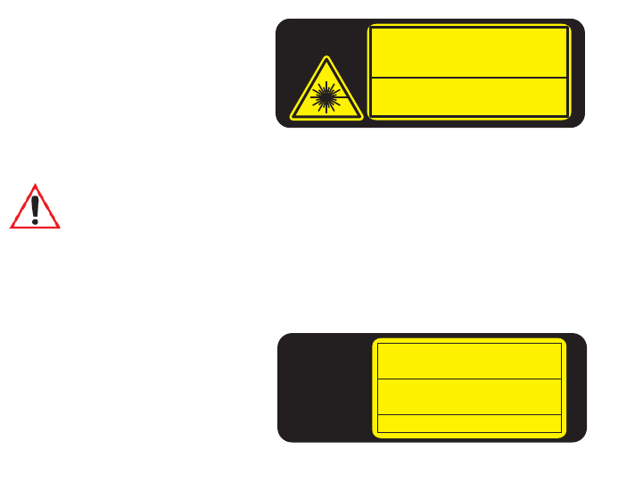
1.4.2 Regulatory Labels
Figure 1.5 Laser Warning Label
Figure 1.6 LED Radiation Notice Label
650-680nm LASER DIODE
Max.Output:1.4mW (SCAN ) <1mW(AIM)
IEC 60825-1:1993+A1:1997+A2:2001
LASER RADIATION
DO NOT STARE INTO BEAM
CLASS 2 LASER PRODUCT (IEC)
CLASS II LASER PRODUCT (CDRH)
1081975
MODEL No:
7545
This label is affixed below the scanner window.
Warning: Using controls or adjustments or performing procedures other than those
specified herein may result in hazardous radiation exposure.
This label is affixed below the scanner window.
1081976
MODEL No:
7545
IEC 60825-1:1993+A1:1997+A2:2001
LED RADIATION
CLASS 1 LED PRODUCT (IEC)
CLASS I LED PRODUCT (CDRH)
This product contains an imager
that uses an LED light source
Preliminary Draft 3

Psion Teklogix 7545 Hand-Held Computer User Manual 11
BASIC CHECKOUT 2
2.1 Features Of The 7545. . . ...............................13
2.2 Preparing The 7545 For Operation . . .........................14
2.2.1 Equipment You Need To Get Started.....................14
2.3 Powering Up The 7545. . ...............................14
2.3.1 Charging The Battery.............................14
2.3.2 Installing The Battery And Switching The Computer On..........15
2.4 Attaching Carrying Accessories . . . .........................16
2.4.1 Attaching The Hand Strap..........................16
2.4.2 Attaching The Pistol Grip ..........................18
2.5 Calibrating The Touchscreen..............................19
2.6 Configuring Your Radio................................19
2.7 Configuring An IEEE 802.11 Radio In The Unit . ..................19
2.7.1 Assigning An IP Address...........................25
2.7.2 Name Servers Tab..............................26
2.7.3 Advanced Features..............................27
2.7.3.1 Rearranging Preferred Networks..................27
2.7.3.2 Deleting A Preferred Network ...................27
2.7.3.3 Changing Network Properties....................28
2.8 Summit Client Utility (SCU) For 802.11b/g Radio..................28
2.8.1 Assigning The IP Address..........................28
2.8.2 Name Servers Tab..............................30
2.8.3 Using The SCU To Connect To The WLAN.................31
2.8.3.1 SSID.................................32
2.8.3.2 EAP Type..............................32
2.8.3.3 Encryption..............................32
2.9 Checking The Scanner.................................33
2.10 Data Transfer Between The 7545 And A PC . . . ..................34
2.10.1 Using Microsoft ActiveSync........................34
2.10.2 Using Windows Vista . . . .........................34
Preliminary Draft 3

Chapter 2: Basic Checkout
Preparing The 7545 For Operation
14 Psion Teklogix 7545 Hand-Held Computer User Manual
2.2 Preparing The 7545 For Operation
Typically, 7545 Hand-Held Computers are configured at the factory and arrive ready for use.
Although these computers are equipped with an internal Compact Flash and SD I/O slot,
these slots are not intended for user modification. If a device needs to be changed or added
in these slots, contact qualified Psion Teklogix personnel.
2.2.1 Equipment You Need To Get Started
You’ll need:
• A compatible battery charger, docking station or portable docking module (PDM)
with power supply.
• An operating wireless network (if you are not operating the equipment in
batch mode).
• A medium (#2) Phillips head screwdriver (if you need to attach a carrying strap or
pistol grip handle).
2.3 Powering Up The 7545
2.3.1 Charging The Battery
Batteries shipped from the factory are not charged. They must be fully charged prior to use.
Full capacity may not be reached until at least 5 full charge/discharge cycles have been per-
formed. Batteries can be charged using a gang charger or the unit’s internal charger. When
using the internal charger, a suitable power source is required. All chargers and docking sta-
tions are described in Chapter 6: “Peripheral Devices & Accessories”.
Note: Psion Teklogix offers a Portable Docking Module (PDM) along with its power sup-
ply to help speed the checkout and confirmation process for your 7545. The PDM
can power your computer with or without a battery installed in the unit. Refer to
Chapter 6: “Peripheral Devices & Accessories” for more information about
this accessory.
Important: The 7545 uses a high capacity lithium-ion battery. Before charging the bat-
tery, it is critical that you review the battery safety guidelines in the 7545
Hand-Held Computer Regulatory & Warranty Guide (PN 8000191).
Preliminary Draft 3

Chapter 2: Basic Checkout
Calibrating The Touchscreen
Psion Teklogix 7545 Hand-Held Computer User Manual 19
2.5 Calibrating The Touchscreen
If you have the 7545 touchscreen feature, it is factory-calibrated and ready-to-go; however,
over time the touchscreen's operating parameters may change, and it may need to be recali-
brated for correct operation. Refer to “Calibrating The Touchscreen” on page 51 for details.
2.6 Configuring Your Radio
Psion Teklogix provides two types of 802.11 Compact Flash (CF) wireless LAN radio cards
for the 7545: the Motorola RA2043a/b/g radio and the Summit RA2041b/g radio. Both
models are Direct Sequence Spread Spectrum radios.
If your 7545 is equipped with an RA2041 CF radio, follow the steps under “Summit Client
Utility (SCU) For 802.11b/g Radio” on page 28 to set up this type of radio for communica-
tion with a wireless LAN.
If your computer is equipped with an RA2043 CF radio, follow the steps outlined under the
heading “Configuring An IEEE 802.11 Radio In The Unit”, below.
2.7 Configuring An IEEE 802.11 Radio In The Unit
The most common 802.11 settings are configured as defaults. However, there are some
fields that must be completed, including the SSID of your access point and the security
methods implemented in the network (including access keys).
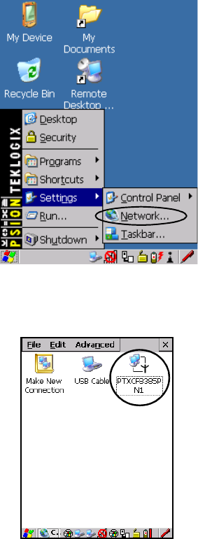
To configure the 802.11 radio:
1. Tap on Start>Settings>Network and Dial-up Connections. (If the Start Menu isn’t
displayed in the taskbar, press [BLUE] [0] to display it.)
Note: Keep in mind that 7545 Hand-Held Computers can be ordered with or without
touchscreens, and that the touchscreen function can be turned off (see “Touch” on
page 124).
Note: In most situations the configuration of your 802.11 radio will require parameters,
settings, and access keys from a network administrator.
Network administrators should review the detailed security information in this sec-
tion in order to effectively configure the 802.11 wireless network.
Important: If the 7545 is equipped with a radio that has never been configured, the
radio settings dialog box opens automatically when the unit is powered on.
In this case, skip to Step 4 on page 21.
Preliminary Draft 3
Chapter 2: Basic Checkout
Configuring An IEEE 802.11 Radio In The Unit
20 Psion Teklogix 7545 Hand-Held Computer User Manual
If you’re using the keyboard, press [BLUE] [0] to display the Start Menu. Use the
[DOWN] arrow key to highlight Settings. Press the [RIGHT] arrow key to display the
sub-menu. Highlight Network, and press [ENTER].
Figure 2.7 Network And Dial-Up Connections
2. Choose the radio icon to open the 802.11 Wireless LAN Settings window. In the
sample screen, this icon is labelled PTXCF8385P N1.
Figure 2.8 802.11 Wireless LAN Icon
Preliminary Draft 3
Chapter 2: Basic Checkout
Configuring An IEEE 802.11 Radio In The Unit
Psion Teklogix 7545 Hand-Held Computer User Manual 21
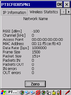
3. Wireless Statistics Tab
When you choose the Wireless LAN icon, an 802.11 Wireless LAN Settings window
(PTXCF8385P N1 in the sample below) is displayed.
This tab lists your radio statistics. Choosing the Zero button resets the statistics of the
last four items: Packets IN, Packets OUT, IN errors and OUT errors.
• Display the next tab in this window, Wireless Information.
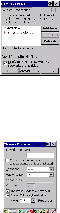
4. Wireless Information Tab
The options under this tab display existing networks to which you can connect, and it
allows you to add a new network or modify the settings for an existing network.
Configure button
• To change the settings in an existing network, highlight the network you want to
modify, and choose the Configure button to display the Wireless Properties dialog
box.
Connect button
• To force connection to a specific, existing network, highlight the network to which
you want your 7545 to connect, and choose the Connect button.
Preliminary Draft 3
Chapter 2: Basic Checkout
Configuring An IEEE 802.11 Radio In The Unit
22 Psion Teklogix 7545 Hand-Held Computer User Manual
This tab lists available networks—any access points that are broadcasting an SSID, and
it lists preferred networks—networks that you have configured. Since access points are
generally secure, they will most likely not be listed here. By default, 7545 attempts to
connect to preferred networks. This behaviour can be changed by enabling
Automatically connect to non-preferred networks in the Advanced Wireless Settings
dialog box (page 27).
• To add a new configuration, tap on the Add New button. A blank Wireless Properties
dialog box is displayed.
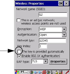
5. Wireless Properties
Network name (SSID)
• Type the appropriate SSID (Service Set Identifier) in the Network name (SSID) text
box at the top of this dialog box.
The Network name field can contain a maximum of 32 characters. The name assigned
here is listed as a preferred network.
Preliminary Draft 3

Chapter 2: Basic Checkout
Configuring An IEEE 802.11 Radio In The Unit
Psion Teklogix 7545 Hand-Held Computer User Manual 23
Ad Hoc And Infrastructure
If you are using an Infrastructure network—one in which 7545s must pass data through
an access point—leave the checkbox next to This is an ad hoc network blank.
If you are using an Ad Hoc network—a network in which 7545s pass data directly to
other 7545s without an access point—highlight This is an ad hoc network, and add a
checkmark in the checkbox to enable Ad Hoc.
Encryption
WEP (Wired-Equivalent Privacy) encryption prevents others from accidentally access-
ing your network. If you are not using encryption, you can choose Disabled from the
drop-down encryption menu. Otherwise, leave this field as is.
TKIP (Temporal Key Integrity Protocol) is an encryption protocol included as part of
the IEEE 802.11 standard for wireless LANs. Designed to enhance WEP, TKIP uses the
original WEP encryption but ‘wraps’ additional code at the beginning and end to encap-
sulate and modify it, encrypting each data packet with a unique encryption key.
Authentication
802.11 supports four subtypes of network authentication services: Open, Shared, WPA,
and WPA-PSK. Under Open authentication, any wireless station can request authentica-
tion. The station that needs to authenticate with another wireless station sends an
authentication management frame that contains the identity of the sending station. The
receiving station then sends back a frame that indicates whether it recognizes the iden-
tity of the sending station.
Under Shared authentication, each wireless station is assumed to have received a secret
shared key over a secure channel that is independent from the 802.11 wireless network
communications channel.
Under WPA and WPA-PSK authentication, the use of 802.1x authentication is required.
For wireless networks without a Remote Authentication Dial-In User Service
(RADIUS) infrastructure, WPA supports the use of a preshared key. For wireless net-
works with a RADIUS infrastructure, Extensible Authentication Protocol (EAP) and
RADIUS is supported.
Important: Keep in mind that the 7545 will only communicate with access points that
are configured with the same SSID.
Note: WEP cannot be disabled if you are using WPA or WPA-PSK authentication.
Preliminary Draft 3
Chapter 2: Basic Checkout
Configuring An IEEE 802.11 Radio In The Unit
24 Psion Teklogix 7545 Hand-Held Computer User Manual
Network Key
This text box is used to specify a 5 or 13 ASCII character sequence or an equivalent 10
or 26 Hexadecimal digit sequence that matches the active WEP key on the access point.
• To assign a Network key, highlight The key is provided automatically, and uncheck
the checkbox to disable this option.
Figure 2.9 Accessing Network Key And Key Index
Key Index
This field is used to identify the WEP key.
• Enter a value from 1 to 4.
Enable 802.1x Authentication
802.1X is the IEEE standard that offers additional security for local area networks. It
provides authentication for user devices attached to an Ethernet network, whether wired
or wireless. A security protocol packet such as TLS or MD5 encapsulated in an EAP is
used in conjunction with the 802.1X standard to authenticate users at the MAC layer.
Available EAPs are listed in the drop-down menu next to the EAP option.
• To activate 802.1X, highlight 802.1x authentication, and check the checkbox.
EAP Type (Extensible Authentication Protocol)
This drop-down menu lists the EAP types available on your system. The items in this -
down menu will vary depending on your network setup. Keep in mind also that some
authentication protocols require that you select a Certificate. By selecting the Properties
button, you will be able to select a Certificate. “Certificates” on page 96 outlines how to
create certificates for your network.
Disable this option to
access Network Key &
Key Index fields.
Preliminary Draft 3
Chapter 2: Basic Checkout
Assigning An IP Address
Psion Teklogix 7545 Hand-Held Computer User Manual 25
Saving and exiting the radio setup. Once you have completed the configuration, press
[ENTER] or tap on OK.
The connection you created will be listed in the Wireless Information tab as a preferred
network. The radio will search for the SSID and will compare the WEP and authentica-
tion information you specified. If there is a match between your computer settings and
the access point settings, the computer will communicate on the network through the
access point.
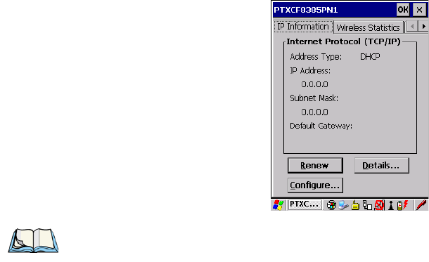
2.7.1 Assigning An IP Address
If your network is not using a DHCP server, you will need to assign an IP address.
•In the PTXCF8385P N1 Settings window, tap on the IP Information tab.
To define a static IP address:
• Tap on the Configure button.
Note: Choosing the Renew button forces the 7545 to renew or find a new IP address. This
is useful if, for example, you are out of communication range for a longer period of
time and your 7545 is dropped from the network.
Preliminary Draft 3
Chapter 2: Basic Checkout
Name Servers Tab
26 Psion Teklogix 7545 Hand-Held Computer User Manual
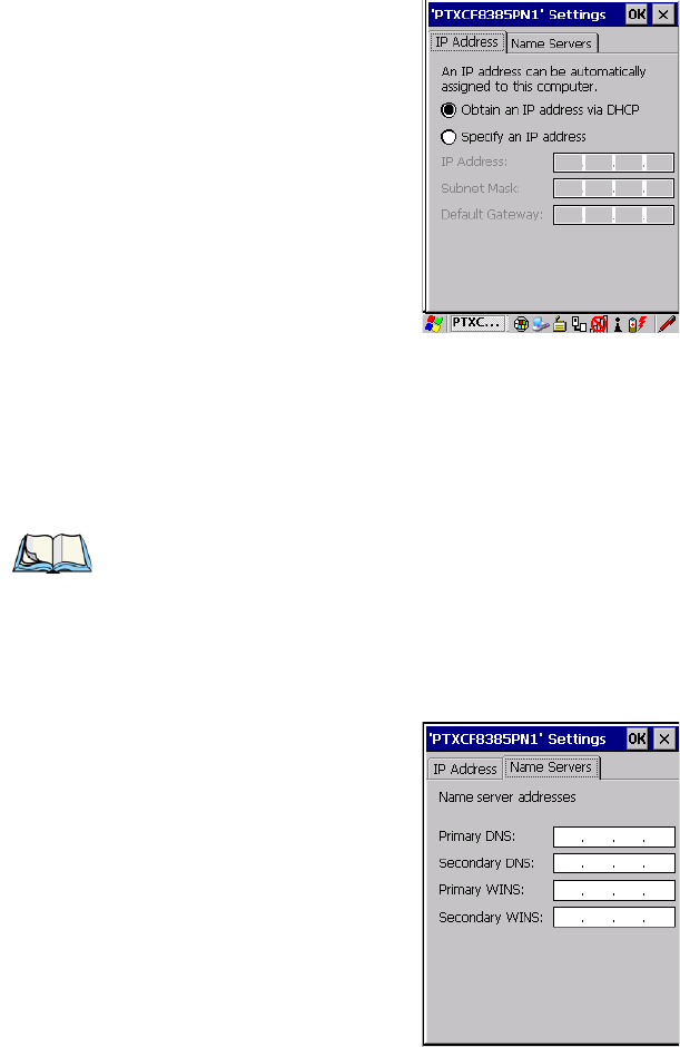
Figure 2.10 Defining An IP Address
• Tap the stylus on the radio button next to Specify an IP address to select it.
• Type an IP, Subnet Mask and Default Gateway address in the appropriate fields. Press
[ENTER] to save your information.
2.7.2 Name Servers Tab
•In the PTXCF8385P N1 Settings window, display the IP Information tab.
•In the IP Information tab, tap on the Configure button.
• Display the Name Servers tab.
Note: If DHCP is enabled, name server addresses are assigned automatically.
Preliminary Draft 3
Chapter 2: Basic Checkout
Advanced Features
Psion Teklogix 7545 Hand-Held Computer User Manual 27
The DNS and WINS fields in the Name Servers tab allow you to specify additional WINS
and DNS resolvers. The format for these fields is ###.###.###.###.
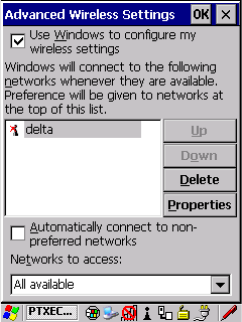
2.7.3 Advanced Features
To display the Advanced Wireless Settings dialog box:
• Tap the Advanced button in the Wireless Information tab.
This window lists the available preferred networks.
2.7.3.1 Rearranging Preferred Networks
The 7545 attempts to connect with the networks listed in this dialog box in sequence, begin-
ning at the top of the list. If you need to rearrange this list of networks, move networks up
and down in the list:
• Move the cursor into the networks list, and highlight the network that you want to
move up or down in the list.
- To move the highlighted item in the list upward or downward, tap on the Up or
Down button.
2.7.3.2 Deleting A Preferred Network
To delete a network from this list:
•In the networks list, highlight the network that you want to remove.
• Tap on the Delete button.
Preliminary Draft 3
Chapter 2: Basic Checkout
Summit Client Utility (SCU) For 802.11b/g Radio
28 Psion Teklogix 7545 Hand-Held Computer User Manual
2.7.3.3 Changing Network Properties
To change the properties of an existing preferred network:
• Highlight the network that you want to modify.
• Tap on the Properties button.
• Make any necessary changes in the Wireless Properties dialog box, and press
[ENTER] to save the changes.
2.8 Summit Client Utility (SCU) For 802.11b/g Radio
This section describes the Summit Client Utility (SCU). The SCU provides the utilities you
will need to configure the 802.11b/g Compact Flash radio module so that it can communi-
cate through a wireless LAN effectively and securely.
2.8.1 Assigning The IP Address
Before launching the SCU, you need to configure how the IP address will be obtained. If
your network is not using a DHCP server, you will need to assign an IP address.
1. Tap on Start>Settings>Network and Dial-up Connections. (If the Start Menu isn’t
displayed in the taskbar, press [BLUE] [0] to display it.)
If you’re using the keyboard, press [BLUE] [0] to display the Start Menu. Use the
[DOWN] arrow key to highlight Settings. Press the [RIGHT] arrow key to display the
sub-menu. Highlight Network, and press [ENTER].
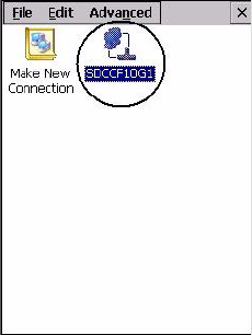
2. Choose the Summit WLAN Adapter icon to open the 802.11 Wireless LAN Set-
tings window. In Figure 2.11, this icon is labelled SDCCF10G1.
Figure 2.11 Summit WLAN Adapter Icon
Preliminary Draft 3
Chapter 2: Basic Checkout
Assigning The IP Address
Psion Teklogix 7545 Hand-Held Computer User Manual 29
The Summit WLAN Adapter Settings menu is displayed (In this screen shown as the
SDCCF10G1 menu).
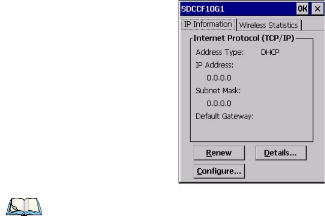
3. Tap on the IP Information tab.
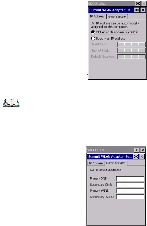
4. To define a static IP address, tap on the Configure button. The Summit WLAN
Adapter Settings menu provides two options:
• Tap on Obtain an IP address via DHCP to have an address assigned automatically,
or
• If you want to use a particular IP address, tap on Specify an IP address, and type the
preferred address as well as the IP, Subnet Mask and Default Gateway addresses in
the appropriate fields. Tap OK to save your information.
Note: Choosing the Renew button forces the 7545 to renew or find a new IP address. This
is useful if, for example, you are out of communication range for a longer period of
time and your 7545 is dropped from the network.
Preliminary Draft 3
Chapter 2: Basic Checkout
Name Servers Tab
30 Psion Teklogix 7545 Hand-Held Computer User Manual
2.8.2 Name Servers Tab
•In the SDCCF10G1 window, display the IP Information tab.
•In the Summit WLAN Adapter Settings>IP Information tab, tap on the
Configure button.
• Display the Name Servers tab.
Note: If DHCP is enabled, name server addresses are assigned automatically.
Preliminary Draft 3
Chapter 2: Basic Checkout
Using The SCU To Connect To The WLAN
Psion Teklogix 7545 Hand-Held Computer User Manual 31
The DNS and WINS fields in the Name Servers tab allow you to specify additional WINS
and DNS resolvers. The format for these fields is ###.###.###.###.
2.8.3 Using The SCU To Connect To The WLAN
This section provides a quick set of steps to create a profile. Detailed information about each
of the SCU tabs—Main, Profile, Status, Diags and Global—is provided in Appendix B:
“SCU For 802.11b/g Radio”. To launch the SCU so that your 7545 can connect to a wireless
LAN:
To launch the SCU so that your 7545 can connect to a wireless LAN:
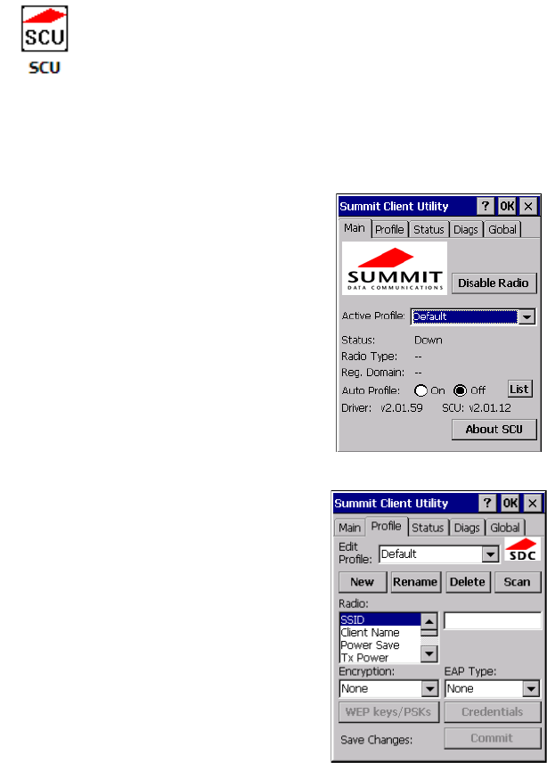
1. Tap on Start>Programs, and then tap on the SCU icon.
Figure 2.12 SCU Main Tab
2. Tap on the Profile tab.
• Tap on the New button to define a new profile.
Preliminary Draft 3

Chapter 2: Basic Checkout
Using The SCU To Connect To The WLAN
32 Psion Teklogix 7545 Hand-Held Computer User Manual
• Type a name using any alpha-numeric combination to uniquely identify this profile.
• Tap on OK to return to the Profile tab.
• Tap on Commit to save the profile name.
• When a pop-up message indicates that your configuration will be saved, tap on OK.
2.8.3.1 SSID
To configure the SSID for the network to which you want to associate:
• Type an SSID in the text box to the right of SSID. This field is limited to
32 characters.
• Tap on Commit and then, in the pop-up message, tap on OK to save your
SSID setting.
2.8.3.2 EAP Type
• Tap on the EAP type drop-down menu, and choose the appropriate type of authenti-
cation—LEAP, EAP-FAST, PEAP-MSCHAP, and PEAP-GTC.
• Next, tap on the Credentials button, and type credentials for IEEE 802.1X
EAP types.
2.8.3.3 Encryption
• Tap on the Encryption drop-down menu, and choose the appropriate type of encryp-
tion—Manual WEP, Auto WEP, WPA PSK, WPA TKIP, WAP2 PSK, WAP2 AES,
CCKM TKIP, CKIP Manual, or CKIP Auto.
If you choose Manual WEP, WPA PSK or WPA PSK:
• Tap on the WEP/PSK Keys button. For Manual WEP, choose up to four static WEP
keys. For PSK, type an ASCII passphrase or hex PSK.
• Configure any other settings that are supplied by the network administrator for the
SSID to which you will associate.
• Make certain that you tap on Commit following each change.
Important: To learn more about the other options available in the radio attributes list,
refer to “Profile” on page B-4.
Important: Refer to “SCU Security Capabilities” on page B-6 for details about security
settings. Additional EAP details are described in “EAP Credentials” on
page B-7.
Preliminary Draft 3

Chapter 2: Basic Checkout
Checking The Scanner
Psion Teklogix 7545 Hand-Held Computer User Manual 33
Once you’ve completed the configuration:
• Tap the Main tab. Tap on the Active Profile button – your new profile will be listed
in the drop-down menu.
When you tap on the profile you created, the 802.11a/b/g radio module attempts to connect
to the network using the following steps:
- Associate to the SSID.
- Authenticate to the network.
- If EAP authentication is being used, derive dynamic encryption keys.
- If DHCP is being used by the network, obtain an IP address.
If the radio is not connecting properly:
• Tap on the Status tab.
The Status dialog box lists the IP and MAC addresses, and indicates the current state of the
radio, the signal strength, channel and so on.
You can go to the Diags tab for DHCP renewal, ICMP Echo Requests (Pings), and
diagnostics.
2.9 Checking The Scanner
If your 7545 is equipped with an internal scanner, you can test it to ensure that it is operating
properly. Point the scanner window at a bar code that your scanner was designed to de-
code—for example, a 1D UPC bar code or 2D bar code. Press the SCAN button or pistol
trigger, and check for a valid decode on the computer’s screen.
Performance is improved if you disable all unneeded bar codes in the Bar Codes screen.
Review Appendix C: “Bar Code Settings” for details about bar codes.
Important: For details about the Status dialog box, refer to page B-9 of Appendix B:
SCU For 802.11b/g Radio.
Note: Details about operating and troubleshooting scanners and RFID readers are pro-
vided under the heading “Internal Scanners” on page 58.
Preliminary Draft 3

Chapter 2: Basic Checkout
Data Transfer Between The 7545 And A PC
34 Psion Teklogix 7545 Hand-Held Computer User Manual
2.10 Data Transfer Between The 7545 And A PC
Data transfer options vary slightly depending on the type of operating system installed in
your PC.
For Windows XP SP2 operating systems or earlier, Microsoft® ActiveSync® is PC connec-
tivity software that can be used to connect your 7545 to PCs running this software.
If the Windows Vista® operating system is installed in your PC, ActiveSync is not required
to transfer data between your 7545 and your PC.
By connecting the 7545 to a PC with a cable you can:
• View 7545 files from Windows Explorer.
• Drag and drop files between the 7545 and the PC in the same way that you would
between PC drives.
• Back up 7545 files to the PC, then restore them from the PC to the hand-held again, if
needed, and so on.
2.10.1 Using Microsoft ActiveSync
To install ActiveSync, follow the step-by-step instructions provided with the program’s
setup wizard. Refer to the following website for details:
http://www.microsoft.com/windowsmobile/activesync/activesync45.mspx
2.10.2 Using Windows Vista
If you have Windows Vista, your 7545 data transfers do not require ActiveSync. To transfer
data between your PC and your 7545:
• Tap on Start>Computer to display the drives. Your 7545 will be visible here.
• Open drives, files and folders as you would on your PC.
Note: When you use an RS-232 serial port to connect devices like the 7545 to your desktop
computer, the connection may not succeed because ActiveSync has trouble connect-
ing at non-default baud rates.
To workaround this problem, set the ActiveSync baud rate on the desktop to use the
same baud rate as the device. You can set the baud rate by editing the registry on the
desktop host computer, as detailed in the steps outlined at the following website:
http://support.microsoft.com/kb/324466
Preliminary Draft 3
Chapter 2: Basic Checkout
Resetting The 7545
Psion Teklogix 7545 Hand-Held Computer User Manual 35
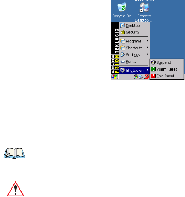
2.11 Resetting The 7545
To perform a Warm or Cold reset, you can access the menu by going to Start>Shutdown. Al-
ternatively you can use the keyboard shortcuts described below.
Warm Reset
To execute a warm reset:
• Press and hold down the [BLUE] key and the [ENTER/ON] key simultaneously for a
minimum of six seconds.
A warm reset closes open applications; any unsaved data are lost. Installed programs and
saved data are preserved.
Cold Reset
To execute a cold reset and access the BooSt menu:
• Press and hold down the [BLUE] key, the [ENTER] key, and the [SCAN] key, simul-
taneously for a minimum of six seconds.
After a cold reset, the BooSt menu appears.
• Type 1 to “Run Main OS” (continue loading the Windows CE operating system).
• If you want a clean start, type ! (that is, the [SHIFT] key and 1). All data and settings
are lost. Files and data stored in flash are preserved.
Note: You do not need to reset your 7545 after configuring the radio.
Important: A cold reset returns the 7545 to factory settings.
Preliminary Draft 3
Preliminary Draft 3

Psion Teklogix 7545 Hand-Held Computer User Manual 37
GETTING TO KNOW YOUR 7545 3
3.1 The Battery.......................................39
3.1.1 Battery Safety ................................39
3.1.2 Removing And Installing The Battery Pack.................39
3.1.3 Battery Chargers...............................40
3.1.4 Monitoring The Battery And Maximizing Run Time............41
3.1.4.1 Storing Batteries...........................42
3.2 Switching The Hand-Held On And Off........................43
3.3 The Keyboard......................................43
3.3.1 Modifier Keys................................44
3.3.1.1 Activating Modifier Keys......................44
3.3.1.2 Locking Modifier Keys.......................45
3.3.2 The Keys...................................45
3.3.3 Function Keys, Softkeys And Macro Keys .................46
3.3.4 Alphanumeric Keyboard: 58-Key......................48
3.5 The Keypad Backlight............................50
3.4 The Display.......................................50
3.4.1 Adjusting The Display Backlight ......................50
3.4.2 Adjusting The Contrast............................51
3.4.3 Calibrating The Touchscreen.........................51
3.5 7545 Indicators .....................................52
3.5.1 LEDs.....................................52
3.5.1.1 Charge LED.............................53
3.5.1.2 Radio Traffic LED .........................53
3.5.1.3 Scan LED..............................54
3.5.1.4 User Application LED .......................54
3.5.2 Onscreen Indicators .............................54
3.5.3 Audio Indicators...............................57
3.5.3.1 Adjusting The Beeper Volume...................57
3.6 Internal Scanners....................................58
3.6.1 Scanning Techniques.............................59
Preliminary Draft 3
38 Psion Teklogix 7545 Hand-Held Computer User Manual
3.6.2 Scan LED Indicators .............................59
3.6.3 Troubleshooting ................................60
3.6.4 Operating One Dimensional (1D) Internal Laser Scanners..........60
3.6.5 Operating Internal PDF Laser Scanners....................60
3.6.6 Operating Internal Two Dimensional (2D) Imager Scanners.........61
3.6.7 Operating RFID/Scanner Modules......................62
3.7 Connecting And Disconnecting Tethered Peripherals .................62
3.8 Monitoring The Network Connection..........................63
3.9 Uploading Data In A Docking Station .........................64
3.10 General Maintenance..................................64
3.10.1 Caring For The Touchscreen.........................64
3.10.2 Cleaning The 7545 . . . ...........................64
Preliminary Draft 3

Chapter 3: Getting To Know Your 7545
The Battery
Psion Teklogix 7545 Hand-Held Computer User Manual 39
3.1 The Battery
The hand-held operates with a lithium-ion battery pack. Preparing the unit for operation re-
quires that a battery pack be charged and installed in the 7545.
3.1.1 Battery Safety
3.1.2 Removing And Installing The Battery Pack
Removing The Battery Pack
• If your unit is equipped with a hand strap, unhook it from the base of the battery.
• Press down the release tab at the top of the battery, and slide the battery out.
Installing The Battery Pack
To install the battery pack:
• Slide the battery pack with the contoured plastic facing you into the 7545. Click the
battery into place.
Important: Before attempting to install, use or charge the battery pack, it is critical that
you review and follow the important safety guidelines in the 7545 Hand-
Held Computer Regulatory & Warranty Guide (PN 8000191).
Important: Always switch the unit off before changing the battery. If you do not turn
the hand-held off before removing the battery, it may be necessary to reboot
the unit. Any active sessions may be lost. While the battery is being
replaced, the 7545 will save its current data for up to 20 minutes.
Note: If your hand-held is equipped with a battery contact protective gasket
(P/N 1020250), to remove the battery, you will need to hold the 7545 face down with
both hands, making certain that your fingers are not touching the keypad. Press
down firmly on the battery release with both thumbs and slide the battery out.
Preliminary Draft 3

Chapter 3: Getting To Know Your 7545
Monitoring The Battery And Maximizing Run Time
Psion Teklogix 7545 Hand-Held Computer User Manual 41
• Quad Docking Station (Model #HU4004): can charge the battery of up to four hand-
helds inserted in the docking station while transferring data through an Ethernet
connection.
• Powered Cradle (Model # HU1010): can charge the hand-held with the battery installed
in the hand-held.
It can take from 1.5 to 4 hours to charge a battery. The unit’s intelligent charging system pro-
tects the battery from over-charging by terminating the charge process when the battery is at
maximum capacity.
3.1.4 Monitoring The Battery And Maximizing Run Time
Under normal operating conditions, fully charged batteries last for 8 hours. As lithium-ion
batteries age, their capacity decreases gradually, and they are generally considered depleted
after approximately 2 years of use (less than 60% of original capacity remaining). Keep in
mind however that heavy usage or operating the 7545 at temperature extremes will shorten
the battery life.
Lithium-ion batteries do not require conditioning cycles and the 7545 battery system (in-
cluding chargers) requires no user interaction to maintain peak performance.
To maximize the run time of your batteries, consider the following:
• The display backlight is the largest drain on the battery. Try to keep its brightness as low
as possible. Adjusting the keyboard backlight also helps.
• The hand-held is ‘event’ driven. That is, when the unit is not in use, it reverts to sleep
mode (even when it appears to be running), saving battery power. Events include a key
press, touchscreen taps and scan triggers. Power consumption is reduced if you avoid
unnecessary events, and allow the unit to sleep as much as possible.
Note: Refer to “Monitoring The Battery And Maximizing Run Time” on page 41 for addi-
tional information about the battery.
Important: To avoid damaging the battery, chargers will not begin the charge process
until the battery temperature is between 0° C (32° F) and 39° C (102° F). If
the battery is too hot or cold, the battery status LED flashes yellow and the
charge is suspended. Refer to Table 3.1: “Charge LEDs” on page 53 for
details.
Preliminary Draft 3
Chapter 3: Getting To Know Your 7545
Monitoring The Battery And Maximizing Run Time
42 Psion Teklogix 7545 Hand-Held Computer User Manual
• The hand-held battery is a ‘smart battery’ with built-in intelligence. The taskbar battery
icon is a linear gauge used to estimate the remaining run time of the battery. It is impor-
tant to note that the battery capacity icon displays quarter percentages of nominal
capacity (the capacity of a new battery). An aged battery, even when fully charged,
shows somewhat less capacity than nominal.
Double-tapping on the battery icon displays a dialog box that provides detailed information
about the battery status and performance. If the remaining capacity indication seems inaccu-
rate, the battery may need recalibration. Recalibration requires that the battery be fully
charged, discharged and then charged again before use. If the battery is fully discharged and
charged on a regular basis, recalibration should not be necessary.
• When the hand-held is switched off, it goes into a low-power, suspend state but contin-
ues to draw a small amount of power from the battery. This should not be an issue unless
the unit is left in suspend state for more than a week—in this case, the battery should be
removed.
• Batteries left unused for durations of more than one or two months should be fully
charged, operated in the hand-held until the battery is empty (i.e. the low battery
warning appears), and then charged again before use. This recalibrates the gas gauge
and allows the internal electronics to determine the actual capacity of the battery. See
“Battery Gas Gauge Calibration” on page 176 for a detailed discussion of battery
calibration.
3.1.4.1 Storing Batteries
Long term battery storage is not recommended. If storage is necessary:
• Always try to use a ‘first-in first-out’ approach to minimize storage time.
• Lithium-ion batteries age much faster at elevated temperatures. Store batteries at tem-
peratures between 0° C and 20°C.
• Always charge batteries to 40 to 60% before storing them. Batteries can be damaged by
an over-discharge phenomenon that occurs when an empty battery is stored for a long
period of time such that the cell voltage drops below a lower limit.
• To minimize storage degradation, recharge stored batteries to 40 to 60% every 4 or 6
months to prevent over-discharge damage.
• A ‘never used’ Li-Ion battery that has been stored for 3 years may have limited or no
useful life remaining once put into service. Think of batteries as perishable goods.
Preliminary Draft 3

Chapter 3: Getting To Know Your 7545
Switching The Hand-Held On And Off
Psion Teklogix 7545 Hand-Held Computer User Manual 43
3.2 Switching The Hand-Held On And Off
Switching On The Unit
• Press and hold down the [ENTER/ON] key for at least one second.
• When all four LEDs flash yellow, release the [ENTER/ON] button.
Switching Off The Unit
To switch off the 7545:
• Press the [BLUE] key, and then press the [ENTER/ON] key.
3.3 The Keyboard
The 7545 offers two types of keyboard layouts: a 58-key keyboard and a 36-key, large
button keyboard. Most of the keys on these keyboards operate much like a desktop com-
puter. Where a key or key function is not consistent with the PC keyboard, the differences
are noted.
Note: If the 7545 is in suspend state, pressing [ENTER/ON] key ‘wakes’ the unit from this
state. The screen in which you were working before the computer entered suspend
state is displayed.
Important: Keep in mind that turning off the 7545 does not result in a complete reboot;
rather, the unit enters a power-saving, “suspend” state. When the 7545 is
turned on from suspend state, operation resumes within a few seconds.
Important: If the word ‘BLUE’ is displayed in uppercase in the taskbar area at the
bottom of the screen, this key is locked “on” and the 7545 will not switch
off. Press the [BLUE] key twice followed by [ENTER/ON] to switch the
7545 off.
If, however, you’ve disabled the “Blue Key” in the ‘One Shot’ dialog box
(see “Keyboard One Shot Modes” on page 105), the 7545 can be turned off
even when the [BLUE] key is locked ‘on’.
Preliminary Draft 3

Chapter 3: Getting To Know Your 7545
The Keys
Psion Teklogix 7545 Hand-Held Computer User Manual 45
3.3.1.2 Locking Modifier Keys
When a modifier key is pressed twice, it is ‘locked’ on. A ‘locked’ modifier key is displayed
in uppercase letters in the taskbar. For example, pressing the [BLUE] key twice locks it
on—it is displayed as BLUE KEY in the taskbar at the bottom of the computer screen.
The locked modifier key will remain active until it is pressed a third time to unlock or turn it
off. Once a modifier key is unlocked, the uppercase representation at the bottom of the
screen is no longer displayed.
3.3.2 The Keys
The [SHIFT] Key
The [SHIFT] key is used to display uppercase alpha characters and provide access to the
symbols above the numeric keys.
The Arrow Keys
The Arrow keys move the cursor around the screen in the direction of the arrow: up, down,
left and right. The cursor is the flashing box or underline character that indicates where the
next character you type will appear.
The [BKSP/DEL] Key
The [BKSP] key (sometimes referred to as destructive backspace) moves the cursor one
character to the left, erasing the incorrectly entered key stroke.
The [DEL] key ([BLUE] [BKSP]) erases the character at the cursor position.
The [CTRL] And [ALT] Key
The [CTRL] and [ALT] keys modify the function of the next key pressed and are application
dependent.
The [TAB] Key
Typically, the [TAB] key moves the cursor to the next field to the right or downward.
Note: The locking function of the [ORANGE] and [BLUE] keys can be disabled so that
pressing either of these keys once will lock the keys ‘on’.
If you disable the ‘One Shot’ function of either of these keys, pressing the [BLUE]
and/or [ORANGE] key once will lock the key ‘on’. Pressing the same key a second
time will unlock or turn it ‘off’. Refer to “Keyboard One Shot Modes” on page 105
for details.
Preliminary Draft 3
Chapter 3: Getting To Know Your 7545
Function Keys, Softkeys And Macro Keys
46 Psion Teklogix 7545 Hand-Held Computer User Manual
The [ESC] Key
Generally, this key is used as a keyboard shortcut to close the current menu, dialog box or
activity and return to the previous one.
The [SPACE] Key
Pressing this key inserts a blank space between characters. In a Windows dialog box, press-
ing the [SPACE] key enables or disables a checkbox.
The [SCAN] Key
Pressing the [SCAN] key—the yellow key with the star-burst scan symbol on it—activates
the scanner beam while pressed. For units that do not have internal scanners, this key can be
re-mapped to another function.
3.3.3 Function Keys, Softkeys And Macro Keys
In addition to the standard keyboard functions (see “The Keyboard” on page 43), The 7545
supports function keys, softkeys and macro keys.
3.3.3.1 Function Keys
58-Key Keyboard Function Keys
The 7545 58-key keyboard is equipped with thirty function keys. Function keys [F1] to [F6]
are located across the top of the keyboard and are directly accessible, a key combination is
not required. Function keys [F7] to [F30] are colour coded in blue print above the alpha keys
and are accessed using a key combination, [BLUE] followed by the appropriate alpha key.
To access function keys [F7] to [F30]:
• Press the [BLUE] key followed by the alpha key to which the function key you want to
use is mapped. For example:
- To access function key [F7], press [BLUE] [C].
- To access function key [F8], press [BLUE] [D], and so on.
Additional function keys, [F11] to [F20], are colour coded in orange print above function
keys [F1] to [F10].
Preliminary Draft 3

Chapter 3: Getting To Know Your 7545
Function Keys, Softkeys And Macro Keys
Psion Teklogix 7545 Hand-Held Computer User Manual 47
To access function keys [F11] to [F20]:
• Press the [ORANGE] key followed by the appropriate function key. For example:
- To access function key [F11], press the [ORANGE] key followed by [F1].
- To access function key [F12], press [ORANGE] followed by [F2], and so on.
To access function keys [F21] to [F30], you’ll need to press [SHIFT] [F1] to [F10]:
• Press the [SHIFT] key followed by the appropriate function key. For example:
- To access function key [F21], press the [SHIFT] key followed by [F1].
- To access function key [F22], press [SHIFT] followed by [F2], and so on.
3.3.3.2 Macro Keys
7545 hand-helds are equipped with a series of macro keys that can be programmed to
replace frequently used keystrokes, along with the function of executable keys like the
[ENTER] key, the [BKSP] key, any function key and arrow key, and so on.
Alphanumeric Keyboard Macro Keys
Alphanumeric (58-keys) keyboards have twelve macro keys: [M1] to [M12]. These keys are
colour coded in orange print above alpha keys [O] to [Z].
To access a macro key:
• Press the [ORANGE] key followed by the appropriate alpha key from O to Z. For
example:
- To access macro key [M1], press [ORANGE] [O].
- To access macro key [M2], press [ORANGE] [P], and so on.
Numeric Keyboard Macro Keys
Numeric keyboards (36-keys) are equipped with six macro keys: [M1] to [M6]. Macro keys
[M1] to [M2] are directly accessible in the bottom row of the keyboard—a key combination
is not required.
Macro keys [M3] and [M4] are colour coded in orange print above macro keys [M1]
and [M2].
• To access [M3], press the [ORANGE] key followed by [M1].
Important: Refer to “Keyboard Macro Keys” on page 106 for details about creating
macros.
Preliminary Draft 3

Chapter 3: Getting To Know Your 7545
Alphanumeric Keyboard: 58-Key
48 Psion Teklogix 7545 Hand-Held Computer User Manual
• To access [M4], press [ORANGE] [M2].
Macro keys [M5] to [M6] are colour coded in blue print above macro keys [M1] and [M2].
• To access [M5], press the [BLUE] key followed by [M1].
• To access [M6], press [BLUE] [M2].
3.3.4 Alphanumeric Keyboard: 58-Key
In addition to alphanumeric keys that are directly accessible on the keyboard (no key combi-
nation is required) and the keys described in this chapter, the 58-key keyboard also provides
function keys and macro keys.
Function keys [F1] through [F24] can be used with the CE operating system or another ap-
plication. The additional function keys, [F25] through [F30] along with the macros, are not
used as part of the Windows CE operating system.
All function keys and macro keys can be custom defined for each application. The TekTerm
application utilizes these keys (for detailed information, see the TekTerm Software User
Manual, P/N 8000073). Refer to “Function Keys, Softkeys And Macro Keys” on page 46
for details about accessing function keys [F25] to [F30].
The examples below illustrate how to access A, B and C, all of which are printed in orange
characters above the numeric key, [2].
To choose the letter ‘a’:
• Press the [ORANGE] key, and press the numeric key [2].
• Press the [ORANGE] key again to unlock or turn it off.
Note: The following examples assume that the [ORANGE] key is enabled as ‘Lock’ mode
in the ‘One Shot’ screen (accessible through the Control Panel Keyboard icon). In
‘Lock’ mode, pressing the [ORANGE] key once locks it ‘on’. Refer to “Keyboard
One Shot Modes” on page 105 for details.
Preliminary Draft 3

Chapter 3: Getting To Know Your 7545
Numeric Keyboard: 36-Key
Psion Teklogix 7545 Hand-Held Computer User Manual 49
To choose the letter ‘b’:
• Press the [ORANGE] key, and press [2] twice.
• Press the [ORANGE] key again to unlock or turn it off.
To choose the letter ‘c’:
• Press the [ORANGE] key, and press [2] three times.
• Press the [ORANGE] key again to unlock or turn it off.
Creating Uppercase Letters
To display a capital letter:
• Press the [ORANGE] key and then the [SHIFT] key before typing the alpha character.
Choosing Multiple Characters From The Same Key
If you need to choose more than one alpha character from a single key, you’ll need to press
the Accept key between alpha selections. The Accept key is presented as an arrow Þ symbol
above the 0 (zero) key.
For example, suppose you want to type the letters ‘a’, ‘b’ and ‘c’. These letters are all acces-
sible from the numeric key, [2].
To type the letter ‘a’:
• Press the [ORANGE] key, and then press the numeric key, [2].
• Press the Accept key [Þ] (zero key) to indicate that the letter ‘a’ should be accepted and
that another letter from the same key will be chosen.
To type the letter ‘b’:
• Press the [2] key twice, and press [Þ] to accept the letter ‘b’.
To type the letter ‘c’:
• Press the [2] key three times.
When you have completed your alpha selections from this key, you can do one of the
following:
• If you want to choose additional alpha characters from another key(s), leave the
[ORANGE] key ‘on’, and press the numeric key with the alpha character you require, or
Note: If you want to use uppercase characters at all times, press [BLUE] [SHIFT]. An
icon of an uppercase ‘A’ is displayed in the taskbar indicating that all letters will be
displayed as uppercase characters.
Preliminary Draft 3

Chapter 3: Getting To Know Your 7545
The Keypad Backlight
50 Psion Teklogix 7545 Hand-Held Computer User Manual
• If you do not want to choose any additional alpha characters, press [ORANGE] again to
unlock or turn ‘off’ the key and end alpha selection.
Choosing Multiple Characters From A Range Of Keys
If you plan on choosing alpha characters from a number of different keys, you are not re-
quired to press the Accept [Þ] key after each alpha selection. The [Þ] key is only required
when you are choosing more than one alpha character from the same key, e.g. ‘a’, ‘b’ and ‘c’
from the [2] key.
Suppose you want to type the letters ‘a’, ‘d’ and ‘g’. These alpha characters are accessed
from the numeric keys [2], [3] and [4].
• With the [ORANGE] key locked ‘on’, press [2] to type the letter ‘a’.
• Press [3] to type ‘d’, and press [4] to type the letter ‘g’.
• To end alpha selection, press the [ORANGE] key again to unlock it.
3.3.6 The Keypad Backlight
The intensity of the keypad backlight and the conditions under which this backlight is acti-
vated can be configured using the Keyboard icon in the Windows CE Control Panel. The
behaviour of the keypad backlight is tailored in the Keyboard Properties dialog box. Refer to
“Keyboard Backlight” on page 104 for details about this option.
3.4 The Display
7545s are equipped with display backlighting to improve character visibility in low light
conditions. The backlight switches on when a key is pressed and the ambient light is below
the set threshold. A light sensor on the front of the hand-held determines the ambient light
level. On some displays, the contrast can also be adjusted to further improve character
visibility.
3.4.1 Adjusting The Display Backlight
The behaviour of the display backlight (the ambient light threshold below which the back-
light will become active) and the intensity of the backlight can be specified in the Display
Properties dialog box in the Control Panel.
Note: Keep in mind that this option may be restricted to supervisory use only.
Note: Refer to “Backlight” on page 99 for details about the Display Properties dialog
box.
Preliminary Draft 3
Chapter 3: Getting To Know Your 7545
Adjusting The Contrast
Psion Teklogix 7545 Hand-Held Computer User Manual 51
3.4.2 Adjusting The Contrast
The display contrast can be adjusted from the unit keyboard using the [BLUE] key and func-
tion keys [F1] and [F2]. Pressing [F1] darkens the display, and pressing [F2]
lightens the display. Keep in mind that adjusting the contrast on a colour display is much
less pronounced than on a monochrome display.
To adjust the display contrast:
• Press the [BLUE] key twice to lock it on, and then press [F1] to darken the display
or [F2] to lighten the display.
• Once you’ve successfully adjusted the display contrast, remember to press the [BLUE]
key again to turn it ‘off’.
3.4.3 Calibrating The Touchscreen
If your 7545 touchscreen has never been calibrated, or if you find that the stylus pointer is
not accurate when you tap on an item, use the Stylus Properties dialog box in the Control
Panel to recalibrate the screen.
•In the Control Panel, choose the Stylus icon to display the Stylus Properties window.
Note: In addition to the manual adjustments described in this section, the display contrast
can also be adjusted using the Windows CE Control Panel. Refer to “Backlight” on
page 99 for details about this dialog box.
Note: Contrast settings are optimized for the maximum readability. However, if the display
jitters or flickers, consider adjusting the contrast at power up.
Preliminary Draft 3
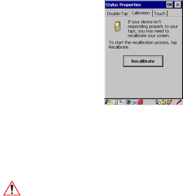
Chapter 3: Getting To Know Your 7545
7545 Indicators
52 Psion Teklogix 7545 Hand-Held Computer User Manual
• Select the Calibration tab, and then choose the Recalibrate button.
• Follow the directions on the calibration screen to calibrate the screen.
3.5 7545 Indicators
7545s use LEDs (Light Emitting Diodes), onscreen messages and audio tones as indicators.
3.5.1 LEDs
Hand-helds are equipped with four tri-coloured LEDs. This section outlines what these
LEDs indicate.
Important: If an LED is illuminated in red, the operator should be cautious as this gen-
erally indicates an abnormal operating condition or active laser emission.
Preliminary Draft 3

Chapter 3: Getting To Know Your 7545
Onscreen Indicators
54 Psion Teklogix 7545 Hand-Held Computer User Manual
3.5.1.3 Scan LED
Successful scans are indicated in two ways: with a scan LED and with an audio tone.
3.5.1.4 User Application LED
This indicator is available for user-loaded custom Windows CE applications. Refer to the
7545 SDK Manual for details about this LED. Neither Windows CE nor TekTerm use this
LED.
3.5.2 Onscreen Indicators
The taskbar at the bottom of the screen displays a variety of system status indicators.
Note: Keep in mind that while the standard 802.11g radio supports the transmit/receive
LED, not all radios support this function.
Table 3.2 Transmit And Receive LEDs
Function Radio Traffic LED Behaviour
Radio Transmit LED flashes yellow.
Radio Receive LED flashes green.
Ta b l e 3 . 3 S c a n L E D
Function Scan LED Behaviour
Scan in progress LED displays solid red during scan.
Successful scan LED displays solid green after decode.
Off when scan ended.
Unsuccessful scan LED flashes red.
Preliminary Draft 3
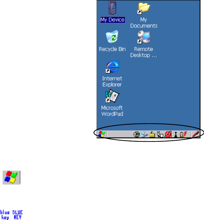
Chapter 3: Getting To Know Your 7545
Onscreen Indicators
Psion Teklogix 7545 Hand-Held Computer User Manual 55
Figure 3.3 Taskbar
The taskbar changes dynamically, and only those icons that are applicable are displayed. For
example, if a radio is not installed in your 7545, the radio signal icon is not displayed in the
taskbar.
Windows® Start Button
If you are using the touchscreen, you can either tap the Windows icon at the bottom left of
the screen, or press [BLUE] [0] to display the Start Menu, and then tap on the desired
application.
Modifier Key Indicators
[SHIFT], [CTRL], [ALT], [BLUE] and [ORANGE] are modifier keys that have onscreen
indicators to show when a key is active or locked. If a modifier key is pressed once to acti-
vate it, the key is displayed in the taskbar in lowercase characters, for example, pressing the
[BLUE] key once displays ‘blue key’ in the taskbar. If a modifier key is pressed twice, it is
‘locked on’ and the onscreen indicator is displayed in uppercase letters in the taskbar, for ex-
ample, pressing [BLUE] twice displays ‘BLUE KEY’ in the taskbar.
Preliminary Draft 3
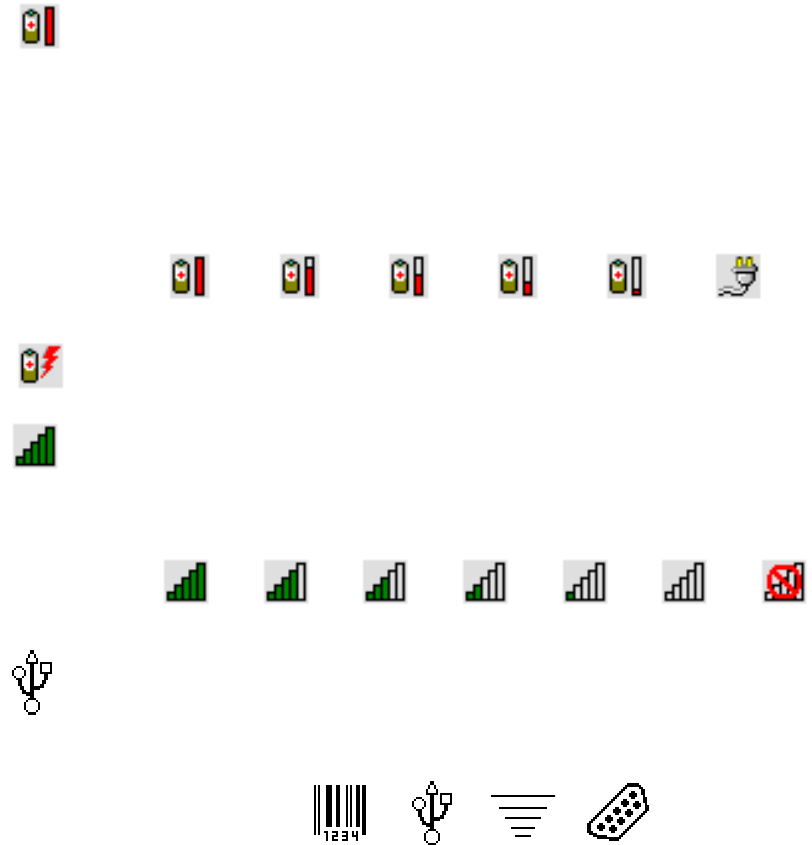
Chapter 3: Getting To Know Your 7545
Onscreen Indicators
56 Psion Teklogix 7545 Hand-Held Computer User Manual
Battery Gauge
The battery shaped icon displayed in the taskbar provides a visual indication of the remain-
ing battery power. The icon acts as a meter that is either full, at three-quarter level, half,
quarter level or empty.
When the battery level is low—approximately 15 minutes from empty—a warning window
pops up. When the battery power is completely depleted, a final warning window indicates
that the 7545 will be powered down.
If the 7545 is using external AC power, an AC icon is displayed in the taskbar.
Battery Charge
The battery charge icon is displayed in the taskbar when the hand-held battery is being
charged.
802.11 Radio Signal Quality
Increasing radio signal quality is represented by longer, filled bars within this icon.
Tethered Devices
When a peripheral is attached to the tether port and activated, an associated icon appears in
the taskbar.
AC ConnectionFull
75%
50% 25% Empty
Good No Radio
Reception
Weak
Reception Link
Scanner RFID Serial DeviceUSB Device
Preliminary Draft 3
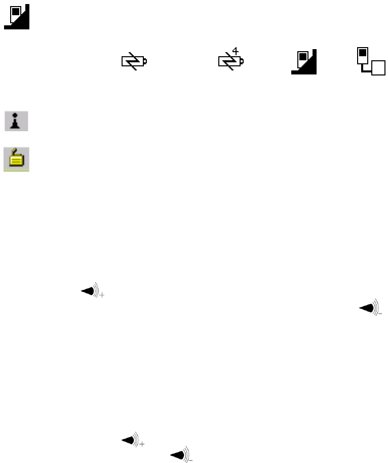
Chapter 3: Getting To Know Your 7545
Audio Indicators
Psion Teklogix 7545 Hand-Held Computer User Manual 57
Docking Device
When a hand-held is inserted in a docking station, charger or cradle, an associated icon
appears in the taskbar.
Bluetooth Radio
This icon displayed in the taskbar represents the installed Bluetooth radio.
Security Level
Security levels can be set to limit user access. In addition, applications can be restricted to
prevent inadvertent changes.
3.5.3 Audio Indicators
The beeper provides a variety of sounds and can be configured to emit a sound when a key is
pressed, a keyboard character is rejected, scan input is accepted or rejected, an operator’s
entry does not match in a match field or the battery is low. The volume function keys are
located in the top row of the keyboard. The increase volume key is labelled with a plus
symbol
and the decrease volume function key is labelled with a minus symbol.
3.5.3.1 Adjusting The Beeper Volume
On 58-key and 63-key keyboards, the volume function keys are accessed by pressing
[BLUE] [F5] and [F6].
On 36-key and 37-key keyboards, the volume function keys are accessed by pressing
[BLUE] [F3] and [F4].
To adjust the beeper volume:
• Press the [BLUE] key twice to lock the key ‘on’ and then, press the increase volume
function key
• or the decrease volume
• function key until the volume meets your requirements.
• Remember to press the [BLUE] key again to turn it ‘off’.
Gang Charger, Combo Charger &
Combo Docking Station
Quad Docking Station Power Cradle Portable Docking
Module (PDM)
Preliminary Draft 3

Chapter 3: Getting To Know Your 7545
Internal Scanners
58 Psion Teklogix 7545 Hand-Held Computer User Manual
3.6 Internal Scanners
The 7545 supports a wide range of scanner options to address a variety of user application
requirements. The scanner installed in your unit can be configured using the Scanner Set-
tings dialog box in the Control Panel (see page 135) and the Manage Triggers application
(see page 113). External, non-decoded scanners are also configured through the Scanner
Settings and Manage Triggers applications.
However, external decoded scanners must be configured by scanning special configuration
bar codes. In these cases, the scanner manufacturer provides programming manuals for con-
figuration purposes.
• For Symbol decoded scanners, refer to the LS3408 Programming Guide
• For Symbol non-decoded scanners, refer to the LS3200 Programming Guide.
• For PowerScan® (PSC) decoded and non-decoded scanners, refer to the PowerScan
Programing Guide (PSC).
Scanner types include:
• Advanced Long Range: reads very large 1D bar codes (60 mil+) at very long distances
(up to 14m).
• Long Range: reads large 1D bar codes (55 mil) at long distances (up to 3m).
• High Performance: reads 1D linear bar codes (5 - 55 mil) at medium distances (up to
1m).
• Extended Range: reads regular 1D bar codes (5 - 55mil) at short to medium distances
(1m), as well as large 1D bar codes (e.g. 55 mil) at long distances.
• RFID: The RD7950 UHF RFID Reader is an EPC-compliant 900MHz RFID reader
which can be integrated with laser bar code scanning or imaging.
• Fuzzy Logic: reads damaged or low contrast regular 1D bar codes (5 - 55mil) at medium
distances (up to 1m).
• PDF Raster Laser: reads 2D PDF bar codes or regular 1D bar codes at short to medium
distances.
• 2D Imager: reads regular 1D and all 2D bar codes at short to medium distances.
• 1D Imager: reads regular 1D and PDF417 bar codes at short to medium distances.
It is critical that you review the “Laser Warnings” in the 7545 Hand-Held Computer Regula-
tory & Warranty Guide (PN 8000191) before using any of the scanners described in this
Important: For detailed scanner specifications and decode zone tables, refer to “Inter-
nal Scanners and Imagers” on page 202.
Preliminary Draft 3

Chapter 3: Getting To Know Your 7545
Scanning Techniques
Psion Teklogix 7545 Hand-Held Computer User Manual 59
chapter. “Scanning Techniques” on page 59 outlines the mechanics of a successful scan. In
addition, review “Scan LED Indicators” on page 59 to better understand how to interpret
whether or not a bar code has been successfully scanned. Finally, “Troubleshooting” on
page 60 provides some helpful suggestions should the scan fail.
3.6.1 Scanning Techniques
• Hold the scanner at an angle. Do not hold it perpendicular to the bar code.
• Do not hold the scanner directly over the bar code. In this position, light can reflect back
into the scanner’s exit window and prevent a successful decode.
• Scan the entire bar code. If you are using a 1D or PDF laser scanner, make certain that
the scan beam crosses every bar and space on the bar code, including the margins on
either end of the symbol.
• If you are using a 2D imaging scanner, make certain the red, oval shaped framing mark
is centered within the bar code you want to scan.
• When using imaging scanners, do not move the scanner while decoding the bar code.
Movement blurs the image.
• Hold the scanner farther away for larger bar codes.
• Hold the scanner closer for bar codes with bars that are close together.
3.6.2 Scan LED Indicators
The scanner LED (the lower-left LED) indicates whether or not your scan is successful. The
LED behaves as follows:
• Scan In Progress: scan LED displays solid red colour.
• Successful Scan: scan LED displays solid green colour and turns off when the scan is
ended.
• Unsuccessful scan: scan LED flashes red.
A bar code icon appears on the screen during a scan. While the scanner beam is active, the
onscreen message states: SCANNING. If you want to turn off the onscreen message, disable
“Scan Indication” in the Options tab of the Scanner Settings menu in the Control Panel
When the scan is successful, the bar code data is displayed on the screen until the scan
button (or pistol trigger) is released, but only if “Scan Result” is turned on in the Options tab
of the Scanner Settings menu in the Control Panel.
Note: The scanning techniques described here apply to internal and external scanners.
Preliminary Draft 3

Chapter 3: Getting To Know Your 7545
Troubleshooting
60 Psion Teklogix 7545 Hand-Held Computer User Manual
3.6.3 Troubleshooting
If the scanner is not working, investigate the following:
• Is the unit on?
• Check that the bar code symbology being scanned is enabled for the hand-held you are
using. Check any other parameters that affect the scanning procedure or the bar code.
• Check the bar code to make sure it is not damaged. Try scanning a different bar code to
verify that the problem is not with the bar code.
• Check that the bar code is within the proper range.
• Does the hand-held display the warning without scanning? This suggests a hardware
problem in the hand-held.
• Is the laser beam scanning across the bar code?
• Once the scan beam has stopped, check the scanner window for dirt or fogging.
3.6.4 Operating One Dimensional (1D) Internal Laser Scanners
• Turn the hand-held on. Wait until the unit has booted up completely.
• Aim at the bar code and press the scan key or the trigger. A scan beam and a warning
indicator appear until a successful decode is achieved or six seconds have elapsed.
3.6.5 Operating Internal PDF Laser Scanners
This scanner decodes PDF417 two-dimensional bar codes.
• Turn the hand-held on. Wait until the unit has booted up completely.
• Aim at the bar code and press the scan key or the trigger. The beam expands into a rec-
tangle covering the bar code to properly scan it. The scan beam and a warning indicator
are visible until a successful decode is achieved or three seconds have elapsed.
Important: If an aiming dot is available on the installed scanner, the dot will be enabled
for a configurable time period (including off), after which normal scanning
begins. Refer to “Dot Time (msec)” on page C-8 for details.
Double-clicking the trigger will override the aiming delay and initiate an
immediate scan. Note that the aiming dot is standard on long-range and
high visibility internal scanners.
Preliminary Draft 3

Chapter 3: Getting To Know Your 7545
Operating Internal Two Dimensional (2D) Imager Scanners
Psion Teklogix 7545 Hand-Held Computer User Manual 61
3.6.6 Operating Internal Two Dimensional (2D) Imager Scanners
An imager scanner takes a snap shot of a single bar code or multiple bar codes (at one time).
It can find a bar code regardless of its orientation—that is, even a bar code printed at a 45
degree angle to the hand-held will be decoded successfully.
Because imager scanners generally have a shorter depth of field than laser scanners, some
practise may be required to find the optimal distance from the types of bar codes being
scanned. Although the imager includes illumination LEDs, ambient light will help the
imager decode the bar codes, especially if the bar code is far from the hand-held.
• Turn the hand-held computer on. Wait until the unit has booted up completely.
• Aim at the bar code and press the scan key or the trigger. Hold the trigger until a suc-
cessful or failed scan result is obtained.
• When the scan button or trigger is pressed, a red, oval shaped light (the framing marker)
is displayed. Centre the framing marker in the field—either in the centre of the bar code
you want to scan or in the centre of the area in which multiple bar codes are to be
scanned.
The illumination LEDs will flash (typically several times) and a picture of the bar code(s)
is taken.
Note: When scanning multiple bar codes, ensure that all of the desired bar codes are
within the field of view of the scanner. It is possible that even when all bar codes are
within the field of view, not all of them will be decoded. Only successfully decoded
bar codes are passed to the application program. The application program then
issues a warning, asking that you scan the missing bar codes.
When scanning a single bar code, ensure that only the desired bar code is within the
field of view of the scanner.
Important: Keep in mind that the imager scanner is a camera, and the LED illumina-
tion is a flash. Glare can be an issue on reflective media such as plastic
coated bar codes, just as glare is an issue for photographers. When pointing
at a shiny surface, either shift the bar code to the side or top, or angle the
bar code so that the glare reflects away from the imager scanner.
Most imagers take several ‘snap shots’ of the bar code in order to decode it.
It is normal for the LEDs to flash two or three times. Hold the unit steady
between flashes to improve decode performance.
Preliminary Draft 3

Chapter 3: Getting To Know Your 7545
Uploading Data In A Docking Station
64 Psion Teklogix 7545 Hand-Held Computer User Manual
3.9 Uploading Data In A Docking Station
The Combo Docking and Quad Docking peripherals allow your hand-held to link to an
Ethernet network. They are typically used to upload transaction data to a server computer
when a radio link is not available. When a 7545 is properly inserted in a docking station, a
dock icon is displayed in the taskbar at the bottom of the unit screen. The hand-held also
detects the presence of the Ethernet network. Review the documentation provided with the
user application installed in your 7545 before preforming data uploads.
3.10 General Maintenance
3.10.1 Caring For The Touchscreen
The touchscreen is covered with a thin, flexible polyester plastic sheet with a conductive
coating on the inside. The polyester can be permanently damaged by harsh chemicals and is
susceptible to abrasions and scratches. Using sharp objects on the touchscreen can scratch or
cut the plastic, or crack the internal conductive coating. The chemicals listed below must not
come into contact with the touchscreen:
• mustard, ketchup
• sodium hydroxide,
• concentrated caustic solutions,
• benzyl alcohol, and
• concentrated acids.
If the touchscreen is used in harsh environments, consider applying a disposable screen pro-
tector (P/N HU6110). These covers reduce the clarity of the display slightly but will
dramatically extend the useful life of the touchscreen. When they become scratched and
abraded, they are easily removed and replaced.
3.10.2 Cleaning The 7545
• Use only mild detergent or soapy water to clean the hand-held unit.
Important: Do not immerse the unit in water. Dampen a soft cloth with mild detergent
to wipe the unit clean.
To prevent damage to the touchscreen, use only the stylus (pen) supplied
with your 7545.
Preliminary Draft 3
Chapter 3: Getting To Know Your 7545
Cleaning The 7545
Psion Teklogix 7545 Hand-Held Computer User Manual 65
• Avoid abrasive cleaners, solvents or strong chemicals for cleaning. The 7545 has a
plastic case that is susceptible to harsh chemicals. The plastic is partially soluble in oils,
mineral spirits and gasoline. The plastic slowly decomposes in strong alkaline solutions.
• To clean ink marks from the keypad and touchscreen, use isopropyl alcohol.
Preliminary Draft 3
Preliminary Draft 3

Psion Teklogix 7545 Hand-Held Computer User Manual 67
WINDOWS EMBEDDED CE 5.0 4
4.1 Navigating In Windows CE And Applications.....................69
4.1.1 Navigating Using A Touchscreen And Stylus................69
4.1.2 Navigating Using The Keyboard.......................69
4.2 Working With Files, Folders And Programs......................71
4.3 The Startup Desktop..................................71
4.3.1 The Desktop Icons..............................72
4.3.2 The Taskbar..................................73
4.3.2.1 Using The Taskbar .........................74
4.3.2.2 Customizing The Taskbar......................74
4.4 The Start Menu.....................................75
4.4.1 The Desktop.................................76
4.4.2 Security Settings...............................76
4.4.3 Programs...................................78
4.4.4 Shortcuts...................................79
4.4.5 Settings....................................81
4.4.6 Run......................................82
4.4.7 Shutdown...................................82
4.5 Using A Dialog Box..................................83
Preliminary Draft 3
68 Psion Teklogix 7545 Hand-Held Computer User Manual
Preliminary Draft 3

Chapter 4: Windows Embedded CE 5.0
Navigating In Windows CE And Applications
Psion Teklogix 7545 Hand-Held Computer User Manual 69
4.1 Navigating In Windows CE And Applications
Graphic user interfaces like Windows CE for portable devices and desktop Windows (2000,
XP, etc.) utilize ‘point and click’ navigation. An equivalent keyboard shortcut is also avail-
able for every ‘point and click’ action.
Windows CE supports the same ‘point and click’ user interface and keyboard shortcuts as
desktop Windows with one difference—the ‘point and click’ action is accomplished using a
touchscreen rather than a mouse. Actions can be performed using any combination of key-
board shortcuts or touchscreen tapping.
4.1.1 Navigating Using A Touchscreen And Stylus
A touchscreen is an optional feature on 7545s. A hand-held equipped with a touchscreen
comes equipped with a stylus—a pointing tool that looks like a pen—stored in a slot at the
top of the unit. The stylus is used to select objects on the touchscreen.
To choose an icon, open a file, launch an applet or open a folder:
• Double-tap the stylus on the appropriate icon.
4.1.2 Navigating Using The Keyboard
If your 7545 has a standard screen (rather than a touchscreen), choosing icons and navigat-
ing dialog boxes, displaying the desktop, and so on requires keyed input. If your unit has
already been fully configured and your application is launched at startup, you’ll have little
need for keyboard navigation, but you can refer to Table 4.1: “Keyboard Navigation” on
page 70 for a description of the navigation keys.
Note: In order to access many of the menus discussed in this chapter, the security level
must be set to ‘Supervisor’ (see “Security Settings” on page 76).
Note: If the touchscreen is not registering your screen taps accurately, the touchscreen
may need recalibration. Refer to “Calibrating The Touchscreen” on page 51.
Note: To prevent damage to the touchscreen, use only the stylus (pen) supplied with
your 7545.
Preliminary Draft 3

Chapter 4: Windows Embedded CE 5.0
Navigating Using The Keyboard
70 Psion Teklogix 7545 Hand-Held Computer User Manual
Keep in mind that unlike a desktop computer, the 7545 does not support key chording
(pressing two keys at the same time). You must press one key followed by the next in se-
quence. Refer to “Working With Files, Folders And Programs” on page 71 for additional
details about keyboard navigation.
Table 4.1 Keyboard Navigation
Operation Key or Key Combination
Switch between active
applications
[ALT] [TAB]
Open task manager [ALT] [ESC]
Move the cursor Arrow keys
Open file, folder or icon [ENTER]
Exit & Save [ENTER]
Close/Exit & Do Not Save [ESC]
Navigate Dialog Boxes [TAB]
To move cursor up [SHIFT] [TAB]
To display the contents of the next ‘tab’ in a
dialog box [CTRL] [TAB]
Select Radio Button/Press Button [SPACE]
Go to Start Menu [BLUE][0]
Preliminary Draft 3
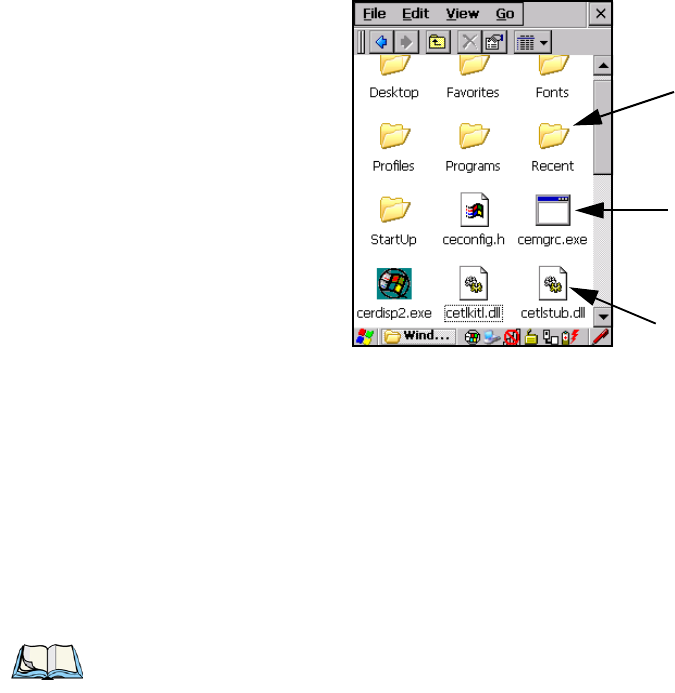
Chapter 4: Windows Embedded CE 5.0
Working With Files, Folders And Programs
Psion Teklogix 7545 Hand-Held Computer User Manual 71
4.2 Working With Files, Folders And Programs
Figure 4.1 Working With Windows Icons
• Double-tap on the appropriate icon—either a folder icon, a program icon or a file
icon—to open or launch your selection.
If you’re using the keyboard:
• Use the arrow keys to highlight the icon you want to open or launch.
• Press [ENTER].
4.3 The Startup Desktop
When the 7545 boots up, the startup desktop (shell) is displayed. Any applications stored in
the Startup folder start up immediately.
Folder
File
Program Icon
Note: The startup folder is located in \Windows\StartUp and \Flash Disk\StartUp.
Preliminary Draft 3
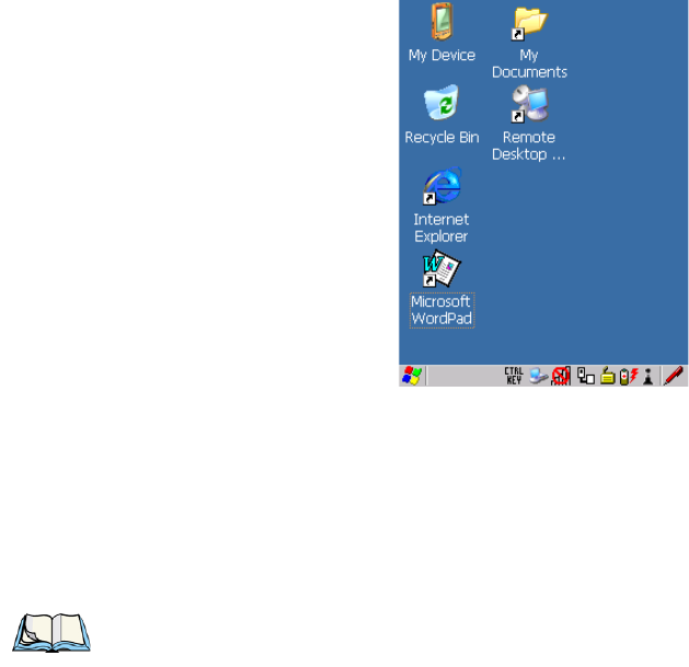
Chapter 4: Windows Embedded CE 5.0
The Desktop Icons
72 Psion Teklogix 7545 Hand-Held Computer User Manual
Figure 4.2 The 7545 Startup Desktop
To access desktop icons:
• Double-tap on the icon to open a window or, in the case of an application icon, launch
an application.
On the keyboard:
• Use the arrow keys to highlight the icon, and press [ENTER] to launch the highlighted
icon.
4.3.1 The Desktop Icons
The icons displayed in the startup desktop operate in much the same way as those displayed
on any standard PC desktop that is running Windows.
My Device
Choosing this icon displays the contents of your 7545 computer. If you’re not sure how to
work with the files, folders and programs displayed, refer to “Working With Files, Folders
And Programs” on page 71.
Recycle Bin
This option temporarily stores items that were deleted, allowing you to either permanently
delete or restore these items.
Note: If the arrow keys do not highlight the desktop icons, the desktop may not be selected.
Press [BLUE] 0 (zero) to display the Start Menu, and select Desktop. Now the desk-
top will be “in focus” and the arrow keys will highlight the icons.
Preliminary Draft 3
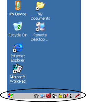
Chapter 4: Windows Embedded CE 5.0
The Taskbar
Psion Teklogix 7545 Hand-Held Computer User Manual 73
Internet Explorer
Choosing this icon launches Internet Explorer—a standard Windows CE version. Keep in
mind that your supervisor will need to set up access using the Internet Options and the
Network and Dial-up Connections icons in the Control Panel.
Remote Desktop Connection
This option allows your 7545 to communicate with a remote desktop PC. “Remote Con-
nect” on page 89 provides a website with step-by-step instructions.
4.3.2 The Taskbar
The 7545 is equipped with a taskbar at the bottom of the screen. It displays icons through
which you can view the battery capacity and radio signal quality of your unit. If the hand-
held is attached to a charger, cradle, docking station or PDM, an associated icon is dis-
played. In addition, the taskbar displays the application(s) currently running on your unit
and the security level assigned to your 7545.
The taskbar also displays active modifier keys: [SHIFT], [ALT], [CTRL], [BLUE] and [OR-
ANGE]. Keys that have been locked “on” are displayed in uppercase letters. For example, if
you have set the [CTRL] key Lock to “on” in the Keyboard menu and you press the key, it is
displayed as CTRL KEY in the taskbar. (For detailed information on modifier keys and key-
board options, see “The Keyboard” on page 43).
Preliminary Draft 3
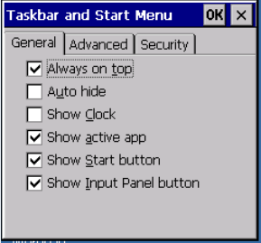
Chapter 4: Windows Embedded CE 5.0
The Taskbar
74 Psion Teklogix 7545 Hand-Held Computer User Manual
4.3.2.1 Using The Taskbar
A tooltip is displayed as each taskbar icon is highlighted. The tooltip provides the status of
each icon.
If you’re using the touchscreen:
• Tap and hold the stylus on an icon to display the icon's tooltip. Double-tap the icon to
open the Control Panel dialog box associated with the icon. For example, double-tap the
battery icon to display a dialog box listing the current battery capacity information.
On the keyboard:
• Press [BLUE] [0] to display the Start Menu.
• Choose Shortcuts from the Start Menu, and then press the [RIGHT] arrow key to
display the sub-menu.
• Choose System Tray in the sub-menu.
• Use the arrow keys to highlight the icon in the taskbar about which you’d like more
information.
• Press [ENTER] to display the appropriate dialog box.
4.3.2.2 Customizing The Taskbar
To customize the taskbar so that it displays only those icons you require:
•In the Start Menu, choose Settings, and then Taskbar.
If you’re using the keyboard:
• Press [BLUE] [0] (zero) to display the Start Menu.
• Highlight the Settings option, highlight Taskbar in the sub-menu, and press [ENTER].
The Taskbar and Start Menu dialog box is displayed.
Preliminary Draft 3
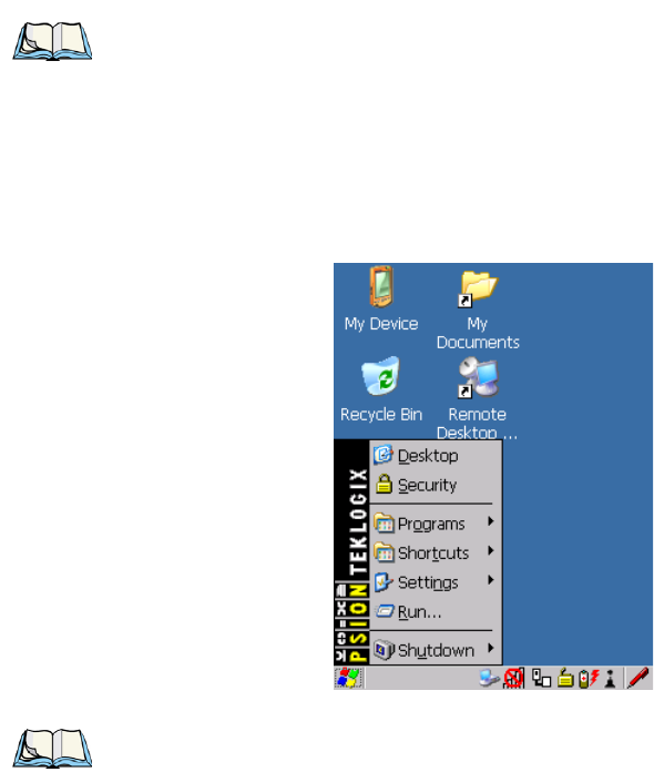
Chapter 4: Windows Embedded CE 5.0
The Start Menu
Psion Teklogix 7545 Hand-Held Computer User Manual 75
• Tap the stylus on the items you want to activate or deactivate. The check mark indicates
active items.
If you’re using the keyboard:
• Highlight the options you want to activate, and press the [SPACE] key to select them. A
check mark indicates active items.
4.4 The Start Menu
The Start Menu lists the operations you can access and work with. It is available from the
startup desktop or from within any application.
To display the menu:
• Press [BLUE] [0] (zero).
If you’re using the keyboard:
• Use the arrow keys to highlight a menu item, and press [ENTER], or
Note: Some of the Start Menu items may be disabled based on the current 7545
security settings.
Note: Tap on the item in the menu with which you want to work.
Preliminary Draft 3
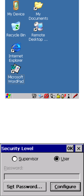
Chapter 4: Windows Embedded CE 5.0
The Desktop
76 Psion Teklogix 7545 Hand-Held Computer User Manual
If the menu item has an underlined character:
• Type the underlined alpha character. For example, to display the Security dialog box,
type the letter ‘s’.
4.4.1 The Desktop
Choosing the Desktop option from the Start Menu displays the 7545 desktop.
4.4.2 Security Settings
Choosing the Security option from the Start Menu displays a dialog box in which you can
define the access level for the 7545: Supervisor or User.
Assigning The Supervisor Security Level
The security level is represented by an icon in the shape of a lock in the taskbar. The security
levels define the options accessible to the operator in the Start Menu and the taskbar. By de-
fault, the security level is set to User, restricting access to only the most basic Start Menu
items.
Preliminary Draft 3
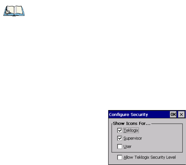
Chapter 4: Windows Embedded CE 5.0
Security Settings
Psion Teklogix 7545 Hand-Held Computer User Manual 77
To allow access to all the Start Menu and taskbar options:
•In the Security Level dialog box, select the radio button next to Supervisor.
•In the Password field, type the Supervisor level password. The default password is
123456.
• Select OK. You can now access all menu items in the Start Menu along with the icons in
the taskbar.
Changing A Password
To assign a password:
• Choose a security level, and enter the existing password in the Password field
• Select the Set Password button.
A dialog box labelled Password Properties is displayed.
• Type the new password in the Password: text box (all keyboard characters are valid).
• In the Confirm Password: text box, retype the new password.
Configuring Security
Choosing the Configure button displays the Configure Security dialog box.
This dialog box allows you to determine which security levels will have an associated icon
displayed in the taskbar. By default, a security icon is not displayed for user-level security.
Note: Keep in mind that this is the same password as that assigned through the Password
control panel applet. Refer to “Control Panel Icons” on page 90.
Preliminary Draft 3
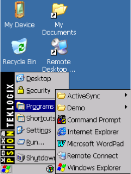
Chapter 4: Windows Embedded CE 5.0
Programs
78 Psion Teklogix 7545 Hand-Held Computer User Manual
4.4.3 Programs
• Choose Programs to display a sub-menu of options.
Figure 4.3 Program Sub-Menu
This sub-menu allows you to choose ActiveSync and Command Prompt, and you can access
the Internet Explorer, installed applications (e.g., Microsoft WordPad), Remote Connect or
Windows Explorer.
ActiveSync®
This option allows you to connect to another device using ActiveSync.
Demo
This folder contains the Demo Imager, Demo Scanner, and Demo Signature applications.
Demo Imager is used for simple image-capturing purposes and for displaying bar code data
and bar code statistics on the same screen with image data and information. Demo Scanner
can be used to test how the hand-held reads and writes RFID tags. Demo Signature allows
you to capture a signature written on the screen with your stylus and save it to a file.
Command Prompt
Command Prompt is used to access the DOS command prompt. At the prompt, you can type
DOS commands such as dir to display all the directories in the drive.
Preliminary Draft 3
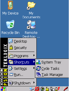
Chapter 4: Windows Embedded CE 5.0
Shortcuts
Psion Teklogix 7545 Hand-Held Computer User Manual 79
Internet Explorer
The 7545 is equipped with Microsoft Internet Explorer for Windows CE. You can access the
Internet Options icon through the Start Menu under Settings, Control Panel or by double-
tapping on the desktop icon My Device and then, double-tapping on the Control Panel icon.
Remote Connect
Remote Connect is a 7545 application used to connect to a Windows Terminal Server so that
you can run a “session” on the Server machine using the 7545 (Windows CE device).
“Remote Connect” on page 89 provides a website with details about this option.
Windows Explorer
The Windows Explorer installed on your 7545 is consistent with all Windows CE devices.
You can access this option from the Start Menu under Programs, Windows Explorer.
4.4.4 Shortcuts
Figure 4.4 Shortcuts Sub-Menu
System Tray
If your touchscreen is not enabled, you can use the System Tray option to access the icons in
the taskbar at the bottom of the screen. The taskbar displays indicators such as a radio signal
icon and the security level. These indicators are attached to dialog boxes that provide addi-
tional information.
• Choose Shortcuts, System Tray.
When System Tray is chosen, the taskbar icons become accessible. To display the dialog box
attached to an icon:
Preliminary Draft 3
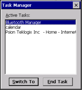
Chapter 4: Windows Embedded CE 5.0
Shortcuts
80 Psion Teklogix 7545 Hand-Held Computer User Manual
• Use the arrow keys to highlight an icon, for example, the security icon.
• Press [ENTER] to display the security level dialog box.
Cycle Tasks
When Cycle Tasks is selected (and the Task Manager is not open), you can cycle through
active applications.
To cycle through your active applications:
• Choose Shortcuts, Cycle Tasks, or
• Press [ALT] [TAB].
Tas k M a na g e r
The Task Manager allows you to switch to another task or to end an active task. To display
the task manager window:
• Tap on Shortcuts, Task Manager, or
• Press [ALT] [ESC].
Preliminary Draft 3
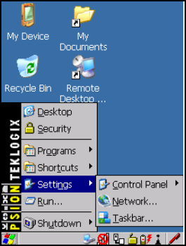
Chapter 4: Windows Embedded CE 5.0
Settings
Psion Teklogix 7545 Hand-Held Computer User Manual 81
4.4.5 Settings
The Settings sub-menu includes the following settings: Control Panel, Network and Dial-
up Connections and Taskbar and Start Menu.
Figure 4.5 Settings Sub-Menu
Control Panel
The Control Panel contains applets used to configure hardware, the operating system and
the shell. If your 7545 is running with the Psion Teklogix TekTerm application or another
application, additional configuration applets may appear in the Control Panel.
Network And Dial-Up Connections
The Network and Dial-up Connections window allows you to configure the 7545 radio or
execute an existing configuration. Refer to “Configuring Your Radio” on page 19 for radio
setup details.
Tas k bar A n d S tar t M e nu
The Taskbar and Start Menu option displays a dialog box in which you can customize the
taskbar, choosing which options will be displayed. Refer to “Customizing The Taskbar” on
page 74 for additional details about this option.
Preliminary Draft 3
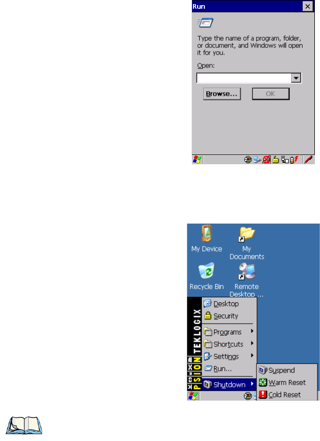
Chapter 4: Windows Embedded CE 5.0
Run
82 Psion Teklogix 7545 Hand-Held Computer User Manual
4.4.6 Run
Choosing the Run option from the Start Menu displays a dialog box in which you can enter
the name of the program, folder or document you want to open or launch.
4.4.7 Shutdown
The Shutdown menu includes these options: Suspend, Warm Reset and Cold Reset.
Note: This menu varies slightly depending on the security level chosen. When the 7545 is
set to User level, the Shutdown option is replaced by Suspend. A sub-menu is not
available.
Preliminary Draft 3
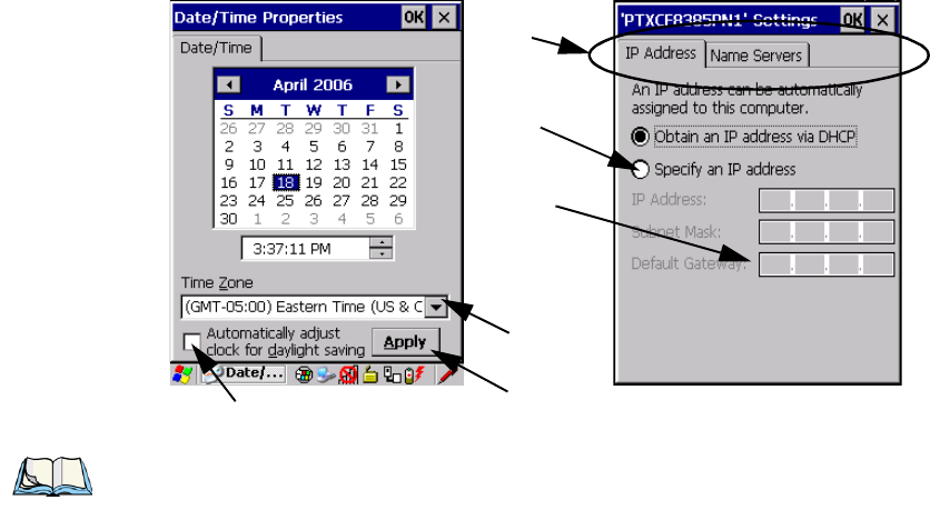
Chapter 4: Windows Embedded CE 5.0
Using A Dialog Box
Psion Teklogix 7545 Hand-Held Computer User Manual 83
Suspend
The Suspend option suspends the 7545 immediately. This is equivalent to turning the hand-
held off.
Warm Reset
The Warm Reset option resets the 7545, leaving all saved files and (registry) settings intact.
Any unsaved data is lost.
Cold Reset
The Cold Reset option resets the 7545 (see page 35). Any files not stored in permanent
memory are lost; however, the registry settings are saved.
4.5 Using A Dialog Box
A dialog box (like the samples in Figure 4.6) appears when you need to make selections and
enter further information. You can move between dialog items by tapping on them with your
stylus, or by pressing the arrow keys and the [TAB] key ([SHIFT] [TAB] moves the cursor
backwards).
Figure 4.6 Dialog Boxes
Checkbox
Drop-down Menu
Button
Textbox
Radio
Button
Tabs
Note: You can use the stylus to tap on an element in a dialog box to select or deselect it,
display drop-down menu items, save your selections, and so on.
Preliminary Draft 3

Chapter 4: Windows Embedded CE 5.0
Using A Dialog Box
84 Psion Teklogix 7545 Hand-Held Computer User Manual
Dialog boxes contain one or more of the following elements:
Tab: A tab separates different elements of a dialog box. Press the [TAB] key until a tab in
the dialog box is highlighted. To display adjoining tabs, press the [RIGHT] or [LEFT] arrow
key. To display the information in the next tab from anywhere in the window, press [CTRL]
[TAB].
Textbox: A textbox requires that you type information. Press the [TAB] key to highlight the
textbox and then type the appropriate information.
Drop-down: This type of menu is identified by up and down arrows next to the drop-down
menu to indicate that additional options are available. Press the [TAB] key to highlight the
menu, and use the arrow keys on your keyboard to cycle through the options.
Checkbox: This box allows you to select or deselect an option. To select or deselect a
checkbox, press the [TAB] key to highlight the checkbox, and press the [SPACE] key to
select or deselect it.
Radio buttons: These buttons allow you to choose from a number of options. For example,
in the sample screen in Figure 4.6 on page 83 you can choose to Obtain an IP address via
DHCP or Specify an IP address. Press the [TAB] key to highlight a radio button option, and
then select a radio button by pressing the arrow keys to highlight the appropriate option.
Buttons: This type of button allows you to Save, Delete and so on the options you’ve chosen
in a dialog box. Use the [TAB] key to highlight the button you want to use. Press the
[ENTER] key to activate it.
Saving Your Choices: Once you’ve made all your changes, press the [ENTER] key to save
your changes and exit the window.
Note: A dialog box item that is displayed in grey text indicates that it is not currently
available.
Preliminary Draft 3

Psion Teklogix 7545 Hand-Held Computer User Manual 85
CONFIGURATION 5
5.1 Remote Connect....................................89
5.2 The TekTerm Application...............................89
5.3 Pocket PC Compatibility................................89
5.4 The Control Panel ...................................89
5.5 Control Panel Icons...................................90
5.6 Control Panel Applications: Basic Setup........................94
5.6.1 App Launch Keys ..............................94
5.6.2 Certificates..................................96
5.6.3 Display Properties..............................97
5.6.3.1 Background.............................98
5.6.3.2 Appearance.............................98
5.6.3.3 Backlight ..............................99
5.6.3.4 Contrast...............................100
5.6.4 Input Panel..................................101
5.6.5 Keyboard Properties .............................102
5.6.5.1 Key Repeat.............................103
5.6.5.2 Keyboard Backlight.........................104
5.6.5.3 Keyboard One Shot Modes.....................105
5.6.5.4 Keyboard Macro Keys .......................106
5.6.5.5 Unicode Mapping..........................108
5.6.5.6 Scancode Remapping........................109
5.6.5.7 Lock Sequence ...........................112
5.6.6 Manage Triggers...............................113
5.6.6.1 Trigger Mappings..........................114
5.6.6.2 Add And Edit Trigger Mapping...................115
5.6.7 Power Management Properties........................117
5.6.7.1 Battery Capacity...........................117
5.6.7.2 Power Saving Suspend.......................118
5.6.7.3 Suspend Threshold And Estimated Battery Backup........119
5.6.7.4 Calibrate...............................120
5.6.7.5 Advanced..............................121
5.6.7.6 Devices...............................122
Preliminary Draft 3
86 Psion Teklogix 7545 Hand-Held Computer User Manual
5.6.7.7 Built In Devices..........................122
5.6.8 Stylus Properties...............................122
5.6.8.1 Double-Tap. . . ..........................123
5.6.8.2 Calibration.............................123
5.6.8.3 Touch................................124
5.6.9 Volume And Sounds Properties . . . ....................124
5.6.9.1 Volume Adjustments........................124
5.6.9.2 Sound Adjustments.........................124
5.7 Bluetooth Setup....................................124
5.7.1 Devices ...................................125
5.7.2 Headset ...................................129
5.7.3 Servers....................................130
5.7.4 Outgoing...................................131
5.7.5 Active Conn. ................................132
5.7.6 Properties..................................133
5.7.7 Search For..................................134
5.8 Error Reporting....................................134
5.9 IPv6 Support......................................134
5.10 Scanner Settings...................................135
5.10.1 Bar Codes .................................136
5.10.1.1 Scanner..............................136
5.10.1.2 Restoring Default Settings....................137
5.10.2 Options...................................138
5.10.2.1 Double Click Parameters . ....................138
5.10.2.2 Display Parameters........................139
5.10.3 Translations ................................140
5.10.3.1 Case Rules ............................142
5.10.4 Ports....................................143
5.10.4.1 Tether Port (COM1) .......................144
5.10.4.2 Console Port (COM3) ......................145
5.10.4.3 Port Replicator Tether (COM6)..................146
5.10.4.4 Port Replicator Port A (COM5) .................147
5.11 SNMP (Simple Network Management Protocol) Setup...............148
5.11.1 Contact...................................148
5.11.2 Communities................................149
5.11.2.1 Adding A Community ......................150
5.11.2.2 Modifying A Community Setting.................150
Preliminary Draft 3
Psion Teklogix 7545 Hand-Held Computer User Manual 87
5.11.2.3 Removing An Existing Community................150
5.11.3 Trap Destination...............................151
5.11.3.1 Enabling Authentication TRAPS.................151
5.11.3.2 Adding A Destination.......................151
5.11.3.3 Changing A Destination......................152
5.11.3.4 Removing A Trap Destination...................152
5.11.4 Permitted Hosts...............................153
5.11.4.1 Adding A Host...........................153
5.11.4.2 Changing A Host..........................153
5.12 The Storage Manager.................................154
5.12.1 Formatting A Memory Card........................154
5.12.2 Creating Partitions .............................155
5.12.3 Partition Management............................156
5.13 Teklogix Error Handling Service...........................158
5.13.1 ErrorLogInfo................................158
5.13.2 NetLog ...................................159
5.14 Teklogix Imagers...................................160
5.15 Total Recall . .....................................161
5.15.1 Creating A Backup Profile.........................161
5.15.2 Restoring A Profile.............................165
5.16 TweakIT Settings...................................166
5.16.1 Advanced..................................166
5.16.1.1 Advanced Interface And Network .................166
5.16.1.2 Advanced Services Settings....................167
5.16.1.3 Advanced Intermediate Driver...................168
5.16.1.4 Radio Features...........................169
5.16.2 User.....................................170
5.16.2.1 Internet Explorer Settings.....................170
5.16.2.2 User Display Settings.......................170
5.16.2.3 User System Settings .......................171
5.16.3 Registry Editor...............................172
Preliminary Draft 3
Preliminary Draft 3

Chapter 5: Configuration
Remote Connect
Psion Teklogix 7545 Hand-Held Computer User Manual 89
5.1 Remote Connect
Remote Connect is a 7545 application used to connect to a Windows Terminal Server so that
you can run a “session” on the Server machine, using the 7545 (Windows CE device).
Refer to the following website for step-by-step information about setting up this connection:
http://www.microsoft.com/WindowsXP/pro/using/howto/gomobile/remotedesktop/default.asp, or contact
Psion Teklogix support services.
5.2 The TekTerm Application
TekTerm is a powerful emulation application ideally suited for real time data transaction ap-
plications associated with mainframes and servers. The 7545 includes unique features that
support TekTerm—a Psion Teklogix application that has the ability to maintain multiple si-
multaneous sessions with a variety of host computers. For detailed information, please refer
to the TekTerm Software User Manual, P/N 8000073.
5.3 Pocket PC Compatibility
The 7545 supports the AYGShell API set that allows Pocket PC-compatible applications to
run on the hand-held. Windows CE includes application programming interface (API) com-
patibility support for the Microsoft Windows Powered Pocket PC 2002 shell in units
running Windows CE.
The website listed below describes the APIs exposed through AYGShell and the application
compatibility between Windows Powered Pocket PC 2002-based applications and Windows
CE-based devices:
http://msdn.microsoft.com/library/default.asp?url=/library/en-us/dncenet/html/WINCENET_CEPCC_App.asp
5.4 The Control Panel
The Windows CE Control Panel provides a group of applications through which you can set
a variety of system-wide properties, such as mouse sensitivity, network configuration and
the desktop color scheme.
When the 7545 boots up, the startup desktop (shell) is displayed, and any applications stored
in the Startup folder start up immediately.
To access the Control Panel:
• Press [BLUE] [0] to display the Start Menu.
Note: If you are uncertain how to move around a dialog box and make selections, review
“Using A Dialog Box” on page 83.
Preliminary Draft 3

Chapter 5: Configuration
Control Panel Icons
90 Psion Teklogix 7545 Hand-Held Computer User Manual
• Use the stylus to tap on Settings>Control Panel.
If you’re using the keyboard:
• Press [BLUE] [0] to display the Start Menu.
• Highlight Settings in Start Menu, and press the [RIGHT] arrow key to highlight the
Control Panel.
• Press the [ENTER] key.
The Control Panel folder contains icons used in the setup of your 7545.
Figure 5.1 Control Panel Icons
5.5 Control Panel Icons
The Control Panel provides a group of applications that allow you to customize and adjust
settings on your 7545. This section shows the related icons in the Control Panel and gives a
Preliminary Draft 3

Chapter 5: Configuration
Control Panel Icons
Psion Teklogix 7545 Hand-Held Computer User Manual 91
brief description of each. Section 5.6: “Control Panel Applications: Basic Setup” describes
the basic configuration for these applications.
App Launch Keys
By mapping keys to applications using this program, you can then launch those applications
from a single key-press.
Bluetooth Devices
Provides options for Bluetooth radio setup. It also provides the capability to use a Bluetooth-
enabled cellular phone as a data modem to exchange information with other Bluetooth
devices and provide network access.
Certificates
A public key is transmitted as part of a certificate. The certificate assigned through this icon
is used to ensure that the submitted public key is, in fact, the public key that belongs to the
submitter. The client checks that the certificate has been digitally signed by a certification
authority that the client explicitly trusts. “Certificates” on page 96 directs you to the appro-
priate setup information.
Date/Time
Allows you to set the current Month, Date, Time, and Time Zone on your unit.
Dialing
Specifies dialing settings, including area code, country code, dial type and the code to
disable call waiting. You can store multiple patterns—for example, ‘Work’, ‘Home’, and so
on using this dialog box.
Display
Changes the appearance (window colour scheme) on the unit desktop.
Error Reporting
Allows you to enable or disable Microsoft error reporting prompts.
Input Panel
Provides the framework for a Soft Input Panel (SIP) should you need to design your own
SIP, or change some soft keyboard options.
Preliminary Draft 3

Chapter 5: Configuration
Control Panel Icons
92 Psion Teklogix 7545 Hand-Held Computer User Manual
Internet Options
Provides options to configure your Internet browser. You can determine items such as the
default and search page that the browser applies when connecting to the Internet, the cache
size, the Internet connection options, and the security level that is applied when browsing.
IPv6 Support
Refers to a new Internet Protocol specification (version 6) that has been published to use
128-bit IP addresses (replacing version 4).
Keyboard
Toggles character repeat on and off and specifies delay and rate for repeated characters. It
also allows you to adjust the keyboard backlight threshold and intensity.
Manage Triggers
Allows multiple-scanner trigger management, including the ability to configure each of the
trigger buttons. You can configure the trigger ID for each trigger button for both single- and
double-click, and the double-click time.
Network And Dial-up Connections
Displays a network window from which the 7545 802.11g radio can be configured and an
existing configuration can be executed. Refer to “Configuring Your Radio” on page 19 for
details.
Owner
Provides fields in which you can specify owner information. A Notes tab allows additional
information to be entered and displayed when the unit is powered up. Network ID tab infor-
mation is used to access network resources. (This information should be provided by your
System Administrator.)
Password
Allows you to assign a password to restrict access to elements of the unit. Once assigned,
password access cannot be circumvented so it is important that you write down your pass-
word and keep it in a safe place. Refer to “Security Settings” on page 76 for details.
PC Connection
Enables direct connections to a desktop computer. Selecting the Change Connection button
allows you to change the type of direct connect to your PC.
Preliminary Draft 3
Chapter 5: Configuration
Control Panel Icons
Psion Teklogix 7545 Hand-Held Computer User Manual 93
Power
Displays battery pack power status. (Alternately, battery status can be accessed through the
taskbar.) Additional tabs allow you to determine suspend states, specify a suspend threshold
and, when seated in either the Combo Dock or Quad Dock, determine whether or not a
battery that requires it can be recalibrated. This dialog box also allows you to activate card
slots. (Refer to “Devices” on page 122 for details.)
RDC Licenses
The Terminal Services license server stores all license tokens that have been installed for a
group of terminal servers and tracks licenses issued. The Remote Desktop Licenses (RDC)
application displays license ‘tokens’ for devices that connect to a Terminal Server.
Region & Language
Allows you to specify the local language that is to be displayed on the hand-held screen
along with the format of numbers, currency, time and date for your region.
Remove Programs
Lists the programs that can be removed from your unit. To remove a program, select it and
then click on the Remove button.
SNMP
SNMP (Simple Network Management Protocol) is the protocol used to monitor and manage
devices attached to a TCP/IP network.
Storage Manager
Allows you to view information about the storage devices that are present, such as SD-
MMC flash cards. For details, see page 154.
Stylus
Adjusts how Windows CE recognizes your double-tap (as slow or rapid successive taps). In
the Calibration tab, you can recalibrate your touchscreen by tapping on the Recalibrate
button and following the directions on the screen.
System
Displays system and memory properties. In the Memory tab, you can allocate memory
between storage memory and program memory.
Preliminary Draft 3

Chapter 5: Configuration
Control Panel Applications: Basic Setup
94 Psion Teklogix 7545 Hand-Held Computer User Manual
Teklogix Error Handling Service
Is an error diagnostic tool that enables you to log error messages to report to Psion Teklogix.
Teklogix Scanners
Provides scanner parameters and the bar code symbologies that the 7545 scanner will suc-
cessfully read.
Tek l ogi x Ima g er s
The Teklogix Imagers applet is used to create, modify, delete, and activate imager settings.
This icon is only present when the appropriate imager is installed. For detailed information,
see Appendix D: “Teklogix Imagers Applet”.
To t a l R e c a l l
Provides access to a backup and restore utility to maintain applications and settings over
cold reboots.
TweakIT Settings
Allows you to change Advanced System Settings (interface, network, and servers), User
System Settings (display font size), and provides the Registry Editor.
Volume & Sounds
Allows you to adjust the volume of the sound emitted to indicate events like warnings, key
clicks and screen taps.
Wireless WAN
When the appropriate radio is available, provides access to technology like GSM/GPRS,
which allows wide area networking capability such as internet browsing.
5.6 Control Panel Applications: Basic Setup
5.6.1 App Launch Keys
The App Launch Keys icon allows you to map a key to an application so that you can then
launch the application from a single key-press.
•In the Control Panel, choose the App Launch Keys icon.
Preliminary Draft 3
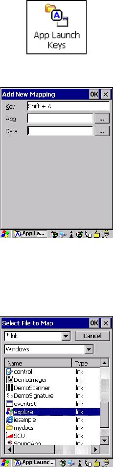
Chapter 5: Configuration
App Launch Keys
Psion Teklogix 7545 Hand-Held Computer User Manual 95
To assign an application key:
• Tap the Add button.
• Press the key you want to use to launch an application. (If an unsupported key is
pressed, a message appears on this screen letting you know.)
The cursor moves to the App field and a new screen is displayed where you can choose the
application to which you want to assign the application key. If you need to, you can Browse
through the information in your 7545 until you locate the application you want to launch.
• Once you’ve selected the file you want to map, tap on OK.
Preliminary Draft 3
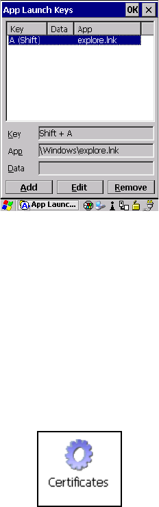
Chapter 5: Configuration
Certificates
96 Psion Teklogix 7545 Hand-Held Computer User Manual
The cursor moves to the Data field. You can use this field if you need to define special pa-
rameters to your application launch key. If you don’t want to assign any parameters, you can
leave the Data field blank. If, for example, you want to assign an application launch key to
launch the WordPad application, you can leave this field blank. If you want to assign an ap-
plication launch key that will open a specific document in the WordPad application, you
need to browse to and choose that document while the cursor is in the Data field.
• Tap on OK.
• If you need to Edit, Remove or Add another App Launch Key, you can do it from this
final screen. Otherwise, tap on OK to save your Application Launch Key.
• To launch the application you chose, press the application key you assigned.
5.6.2 Certificates
A public key is transmitted as part of a certificate. The certificates listed in the Certificates
tabs ensure that the submitted public key is, in fact, the public key that belongs to the sub-
mitter. The 7545 checks that the certificate has been digitally signed by a certification
authority that the 7545 explicitly trusts. This option is used in conjunction with 802.1x au-
thentication to enhance 7545 security.
•In the Control Panel, choose the Certificates icon.
Your 7545 has certificates already preinstalled in the computer. My Certificates establish
your identity, Other Authorities certificates identify intermediate certification authorities,
Preliminary Draft 3
Chapter 5: Configuration
Display Properties
Psion Teklogix 7545 Hand-Held Computer User Manual 97
and Trusted Authorities certificates establish the identity of the servers with which you
can connect.
You can import or remove certificates, and view certificate information for any listing, in-
cluding names, dates, serial numbers, etc.
5.6.3 Display Properties
•In the Control Panel, choose the Display icon.
Note: When importing certificates, the 7545 only recognizes .cer files.
Preliminary Draft 3
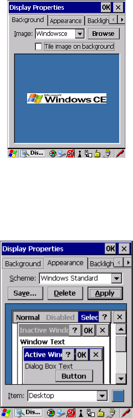
Chapter 5: Configuration
Display Properties
98 Psion Teklogix 7545 Hand-Held Computer User Manual
5.6.3.1 Background
•In the Display Properties dialog box, open the Background tab.
This dialog box allows you to customize your background image.
5.6.3.2 Appearance
•In the Display Properties dialog box, open the Appearance tab.
This dialog box allows you to customize the display colour scheme.
Preliminary Draft 3
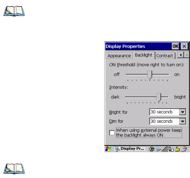
Chapter 5: Configuration
Display Properties
Psion Teklogix 7545 Hand-Held Computer User Manual 99
5.6.3.3 Backlight
The backlight is activated for a configurable amount of time if the ambient light is below a
specified threshold and if the 7545 is in use (key press, scanner trigger). The Display Prop-
erties dialog box in the Control Panel allows you to specify the intensity of the backlight
along with how the backlight behaves in low-light conditions and when the unit is not in use.
•In the Display Properties dialog box, open the Backlight tab.
ON Threshold
The 7545 is equipped with an ambient light sensor. This sliding bar allows you to determine
how dark the ambient light needs to be before the backlight turns on.
Intensity
This parameter is used to adjust the light intensity of the 7545 backlight. Sliding the bar to
the left lowers the light intensity, and sliding it to the right raises the intensity.
Note: Keep in mind that this option may be restricted to supervisory use only.
Note: Backlight changes take effect immediately. You do not need to reset the unit.
To maximize battery run time, keep the display backlight brightness and active
durations as low as possible.
Preliminary Draft 3
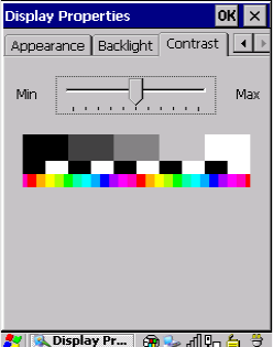
Chapter 5: Configuration
Display Properties
100 Psion Teklogix 7545 Hand-Held Computer User Manual
Bright For
The value chosen from this drop-down menu determines the duration of time that the back-
light stays on at the configured intensity after the last user action (keypress, scan trigger).
Dim For
The value chosen from this drop-down menu determines the duration of time that the back-
light stays on at half the configured intensity (dimmed backlight) after expiration of the
Bright For delay and as long as no user action takes place (such as a keypress or scan trig-
ger). At the expiration of the Dim For duration, the display backlight shuts off.
External Power Checkbox
When you select the checkbox next to When using external power keep the backlight always
ON, the backlight remains ON at the configured intensity when the 7545 is operating with
external power (not battery power). If the 7545 is drawing power from its battery, this option
is ignored and the other parameters defined in Display Properties dialog box take affect.
5.6.3.4 Contrast
The Contrast tab allows you to adjust the display contrast to suit the environment in which
you are using the 7545. The contrast control can also be used to reduce display flickering
that can occur with colour displays in certain lighting conditions.
•In the Display Properties dialog box, open the Contrast tab.
• Slide the bar in the Contrast tab to the left to decrease or darken the display contrast.
• Slide the bar to the right to increase or lighten the display contrast.
Preliminary Draft 3
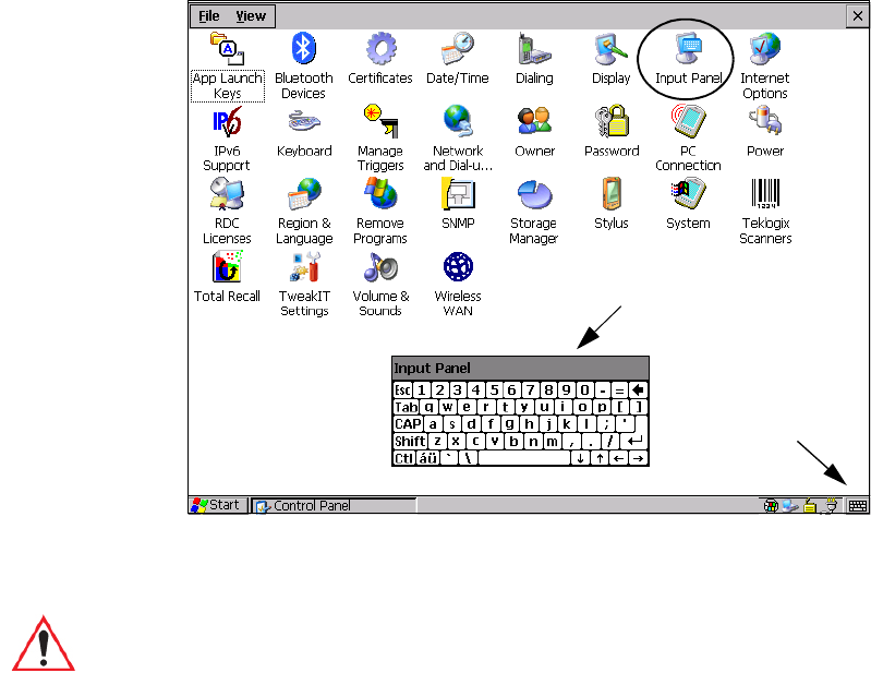
Chapter 5: Configuration
Input Panel
Psion Teklogix 7545 Hand-Held Computer User Manual 101
5.6.4 Input Panel
The 7545 is equipped with at Soft Input Panel (SIP).
Tapping on the Input Panel button displays a soft input panel (soft keyboard) that can be
customized using the Input Panel dialog box.
The soft keyboard operates just like a standard keyboard except that rather than pressing a
key, you tap on letters, numbers, modifier keys, etc. on the 7545 screen.
To customize the appearance and behaviour of the soft keyboard:
• Tap on the Input Panel icon in the Control Panel.
Soft Keyboard
Input Panel
Button Icon
Important: If the Input Panel button icon is not visible in the taskbar, from the ‘Start’
menu, tap on Settings>Taskbar and Start Menu. Tap the checkbox next to
‘Show Input Panel Button’. To remove this icon from the taskbar, tap in the
checkbox to erase the check mark.
Preliminary Draft 3
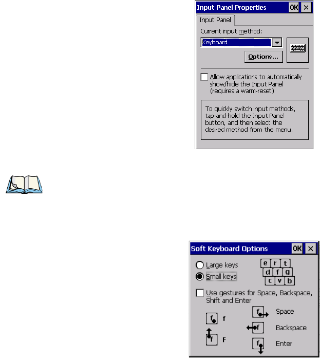
Chapter 5: Configuration
Keyboard Properties
102 Psion Teklogix 7545 Hand-Held Computer User Manual
Figure 5.2 Input Panel Properties
• Tap on the Options button to change the appearance of your soft keyboard.
Figure 5.3 Soft Keyboard Options
5.6.5 Keyboard Properties
This icon displays the Keyboard Properties dialog box in which you can adjust the repeat
rate of the keys, the intensity of the keyboard backlight and the behaviour of the [BLUE]
and [ORANGE] modifier keys. This dialog box also allows you to define macro keys and
Unicode characters.
•In the Control Panel, choose the Keyboard icon.
Note: You can also display this dialog box by double-tapping on the Input icon in the far-
right corner of the taskbar.
Preliminary Draft 3
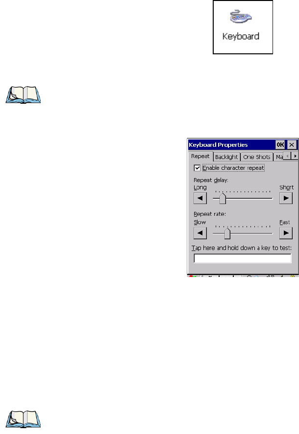
Chapter 5: Configuration
Keyboard Properties
Psion Teklogix 7545 Hand-Held Computer User Manual 103
5.6.5.1 Key Repeat
•In the Keyboard Properties dialog box, open the Repeat tab.
Repeat Delay
The value assigned for this parameter determines the delay in milliseconds between repeat
characters. Sliding the Repeat Delay bar to the left increases the delay between key repeats,
and sliding the bar to the right shortens the repeat delay time.
Repeat Rate
The value assigned for the Repeat Rate parameter determines how quickly the key you press
repeats and is measured in characters per second (cps). Sliding the bar to the left slows the
repeat rate, and sliding the bar to the right increases the repeat rate.
Note: These settings apply when a key is held down continuously.
Note: Use the field at the bottom of this dialog box to test the repeat delay and rate set-
tings you’ve chosen.
Preliminary Draft 3
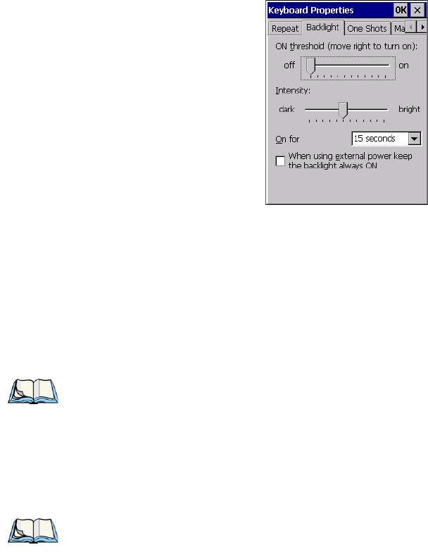
Chapter 5: Configuration
Keyboard Properties
104 Psion Teklogix 7545 Hand-Held Computer User Manual
5.6.5.2 Keyboard Backlight
•In the Keyboard Properties dialog box, open the Backlight tab.
ON Threshold
The ON Threshold sliding bar allows you to determine how dark the ambient light needs to
be before the keyboard backlight turns on.
Intensity
This parameter is used to adjust the light intensity of the 7545 keyboard backlight. Sliding
the bar to the left darkens the keyboard backlight intensity, and sliding it to the right lightens
the intensity.
ON For
The value chosen from this drop-down menu determines the duration of time that the key-
board backlight stays on after the last user action (keypress or scan trigger).
Note: The keypad backlight maximum brightness will decrease over time as it ages. Use
mid-range intensity settings when possible to extend the backlight lifespan. When
the backlight starts to dim, use this parameter to make it brighter.
Note: Tapping in the checkbox next to ‘When using external power, keep the backlight
always ON’ forces the keypad backlight to remain on when the unit is operating
with external power.
Preliminary Draft 3
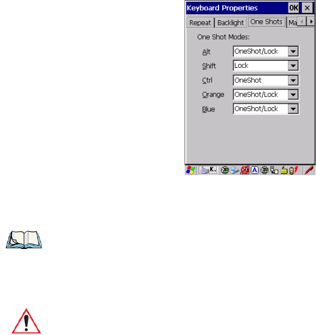
Chapter 5: Configuration
Keyboard Properties
Psion Teklogix 7545 Hand-Held Computer User Manual 105
5.6.5.3 Keyboard One Shot Modes
•In the Keyboard Properties dialog box, open the One Shots tab.
The options in this tab allow you to determine how modifier keys on your 7545 behave. For
each modifier key—[ALT], [SHIFT], [CTRL], [ORANGE] and [BLUE]—you have the fol-
lowing options in the drop-down menu: Lock, OneShot, and OneShot/Lock.
Lock
If you choose Lock from the drop-down menu, pressing a modifier key once locks it ‘on’
until you press the modifier key a second time to unlock or turn it off.
OneShot
If you choose OneShot, the modifier key remains active only until the next key is pressed.
Note: Keep in mind that checking the taskbar lets you know whether or not these keys are
locked on. For example, if the [ORANGE] key is locked ‘on’, the taskbar at the bot-
tom of the screen displays it in uppercase characters, ORANGE KEY. If this key is
displayed in lowercase characters in the taskbar, you’ll know that the orange key is
not locked. It will become inactive following a key press.
Important: Once you’ve assigned a One Shot mode to a modifier key, you need to tap
on the OK button at the top of the tab to activate your selection.
Preliminary Draft 3
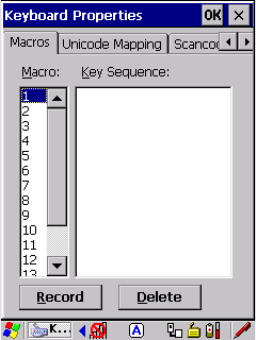
Chapter 5: Configuration
Keyboard Properties
106 Psion Teklogix 7545 Hand-Held Computer User Manual
OneShot/Lock
OneShot/Lock allows you to combine these functions. When you choose this option and you
press the modifier key once, it remains active only until the next key is pressed.
If you press the modifier key twice, it is locked ‘on’, remaining active until the modifier key
is pressed a third time to turn it ‘off’.
5.6.5.4 Keyboard Macro Keys
•In the Keyboard Properties dialog box, open the Macros tab.
A macro has 200 programmable characters (or “positions”). The macro keys can be pro-
grammed to replace frequently used keystrokes, along with the function of executable keys
including [ENTER], [BKSP] and [DEL] ([BLUE]-[BKSP]), function keys and arrow keys.
Recording And Saving A Macro
You can program up to 12 macro keys on a 58-key 7545. On a 36-key 7545, you can
program a maximum of 6 macro keys.
•In the Macro menu highlight a macro key number, for example macro 1, to assign a
macro to macro key [M1]. Choose the Record button.
Preliminary Draft 3
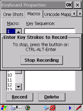
Chapter 5: Configuration
Keyboard Properties
Psion Teklogix 7545 Hand-Held Computer User Manual 107
A message screen is displayed instructing you to Enter Key Strokes to Record
• Type the macro sequence you want to assign to the Macro key. You can type text and
numbers, and you can program the function of special keys into a macro.
• When you’ve finished recording your macro sequence, press the key sequence: [CTRL]
[ALT] [ENTER], or choose the Stop Recording button.
A new screen called ‘Verify Macro’ displays the macro sequence you created. The Save
button is highlighted.
• Press [ENTER] to save your macro, or highlight CANCEL and press [ENTER] to
discard it.
Executing A Macro
To execute a macro:
• Press the macro key to which you’ve assigned the macro. For example, if you created a
macro for macro key 1, press [M1] to execute the macro.
Deleting A Macro
To delete a macro:
•In the Macros tab, highlight the macro number you want to delete.
• Choose the Delete button.
Preliminary Draft 3
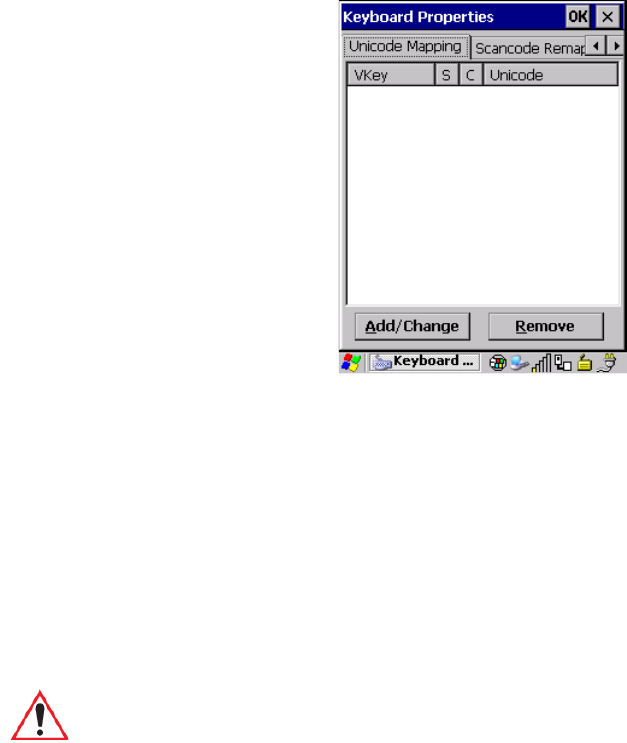
Chapter 5: Configuration
Keyboard Properties
108 Psion Teklogix 7545 Hand-Held Computer User Manual
5.6.5.5 Unicode Mapping
•In the Keyboard Properties dialog box, open the Unicode Mapping tab.
The Unicode Mapping tab is used to map combinations of virtual key values and [CTRL]
and [SHIFT] states to Unicode™ values. This tab shows the configured Unicode character
along with the Unicode value. For example, the sample screen above shows “a (U+0061)”
indicating that the character “a” is represented by the Unicode value “0061”, and so on.
Keep in mind that Unicode configurations are represented as hexadecimal rather than
decimal values.
All user-defined Unicode mappings are listed in the Unicode Mapping tab in order of virtual
key value, and then by order of the shift state. If a Unicode mapping is not listed, the
Unicode mapping is mapped to the default Unicode value.
Adding And Changing Unicode Values
Important: Changes to Unicode mappings are not saved until you exit the Keyboard
Properties dialog box.
Preliminary Draft 3
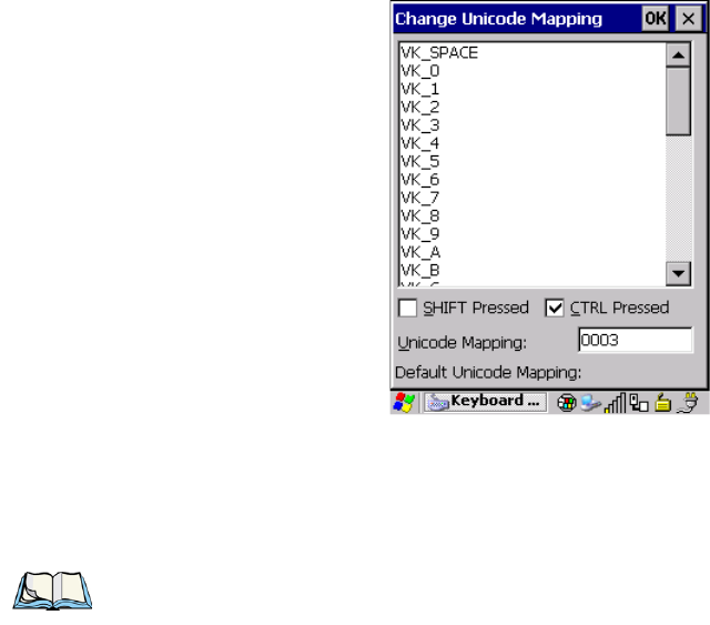
Chapter 5: Configuration
Keyboard Properties
Psion Teklogix 7545 Hand-Held Computer User Manual 109
• Choose the Add/Change button.
• Highlight a value in the Unicode mapping list. In the sample screen above, a value will
be assigned to virtual key 0 (VK 0).
• Position the cursor in the Unicode Mapping field, and type a Unicode value for the
highlighted key.
Removing Unicode Values
•In the Unicode Mapping tab, highlight the item you want to delete, and choose the
Remove button.
5.6.5.6 Scancode Remapping
A scancode is a number that is associated with a physical key on a keyboard. Every key has
a unique scancode that is mapped to a virtual key, a function or a macro. Scancode Remap-
ping allows you to change the functionality of any key on the keyboard. A key can be
remapped to send a virtual key (e.g. VK_F represents the ‘F’ key; VK_RETURN represents
the [ENTER/ON] key, etc.), perform a function (e.g. turn the scanner on, change vol-
ume/contrast, etc.) or run a macro.
There are three different tables of scancode mappings: the Normal table, the Blue table and
the Orange table. The Normal table defines unmodified key presses; the Blue table defines
Note: To add a shifted state, [SHIFT] and/or [CTRL], press [TAB] to position the cursor
in the checkbox next to ‘SHIFT Pressed’ and/or ‘CTRL Pressed’. Press [SPACE] to
select the shift state you want to assign.
Preliminary Draft 3
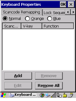
Chapter 5: Configuration
Keyboard Properties
110 Psion Teklogix 7545 Hand-Held Computer User Manual
key presses that occur when the [BLUE] modifier is on; the Orange table defines key
presses that occur when the [ORANGE] modifier is on. The default mappings of these scan-
codes can be overwritten for each of these three tables using the Scancode Remapping tab
accessed from the Keyboard Properties dialog box.
The first column in the Scancode Remapping tab displays the scancodes in hexadecimal. If
the scancode is remapped to a virtual key, that virtual key is displayed in the next column la-
belled ‘V-Key’. A virtual key that is ‘Shifted’ or ‘Unshifted’ is displayed in the third column
labelled ‘Function’.
If the scancode is remapped to a function or a macro, the first and second columns remain
blank while the third column contains the function name or macro key number
(e.g., Macro 2).
Adding A Remap
To add a new remapping:
• Choose the Add button at the bottom of the dialog box.
Preliminary Draft 3
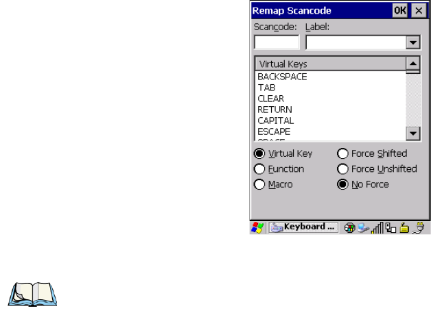
Chapter 5: Configuration
Keyboard Properties
Psion Teklogix 7545 Hand-Held Computer User Manual 111
The Remap Scancode dialog box is displayed.
• Type the scan code in hexadecimal in the field labelled Scancode
Virtual Key, Function And Macro
The radio buttons at the bottom of the dialog box allow you to define to what the scan code
will be remapped: Virtual Key, Function or Macro.
When Virtual Key is selected, you can choose to force [SHIFT] to be on or off when the
virtual key is sent. If No Force is selected, the shift state is dependent on whether the shift
state is on or off at the time the virtual key is sent.
When Function is selected, a list of valid functions appears in the dialog box.
When Macro is selected, the macro keys available on your unit are listed in the dialog box.
• Choose Virtual Key, Function or Macro.
• Choose a function from the Function list in the dialog box, and tap on OK.
Editing A Scancode Remap
To edit a scancode:
•In the Scancode Remapping tab, tap the stylus on the remap you want to edit.
• Tap on the Edit button, and make the appropriate changes.
• Tap on OK to save your changes.
Note: The Label field displays the default function of the scancode you are remapping.
Preliminary Draft 3
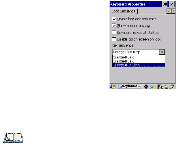
Chapter 5: Configuration
Keyboard Properties
112 Psion Teklogix 7545 Hand-Held Computer User Manual
Removing A Remap
To delete a remap:
•In the Scancode Remapping tab, highlight the scancode you want to delete, and tap on
the Remove button.
• Tap on OK.
5.6.5.7 Lock Sequence
The Lock Sequence menu allows you to lock the 7545 keyboard to prevent keys from being
pressed accidentally when, for example, the unit is inserted in a holster.
• To lock the keyboard, tap in the checkbox next to Enable key lock sequence.
• Tap in the checkbox next to Keyboard locked at startup.
•In the Key sequence drop-down menu, choose the key sequence you will need to type to
unlock the keyboard.
Note: It is useful to leave the ‘Show popup message’ enabled (default) so that anyone
attempting to use the keyboard will see the key sequence they will need to enter to
unlock the keyboard displayed on the screen.
Preliminary Draft 3
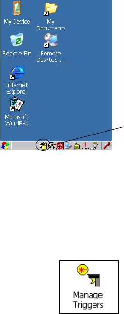
Chapter 5: Configuration
Manage Triggers
Psion Teklogix 7545 Hand-Held Computer User Manual 113
A locked keyboard icon is displayed in the softkey bar when the keyboard is locked.
• Type the key sequence to unlock the keyboard.
5.6.6 Manage Triggers
Allows users to configure how bar code scanners and other devices such as RFID readers
are triggered. You can configure the trigger ID for each trigger button for both single- and
double-click, and the double-click time.
•In the Control Panel, choose the Manage Triggers icon.
Locked Keyboard
Icon
Preliminary Draft 3
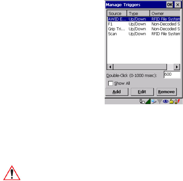
Chapter 5: Configuration
Manage Triggers
114 Psion Teklogix 7545 Hand-Held Computer User Manual
•In the Manage Triggers screen you’ll see a list of trigger mappings.
5.6.6.1 Trigger Mappings
A trigger mapping is an association between a particular key on the keyboard and a driver or
application, the module(s)—sometimes referred to as “trigger consumer(s)”—of the trigger
source. Along with keyboard keys, the external trigger (scan button) is software-based.
When the specified key is pressed, the owner (for example, a decoded scanner) is sent
amessage.
Double-Click
When a key is pressed and released, then pressed again within the configured time (between
0 to 1000 milliseconds), a double-click occurs. See also “Trigger-Press Type” on page 116.
Important: It is not possible to have two or more identical mappings—for example [F1]
cannot be mapped to the Non-Decoded Scanner twice—even if the trigger
type is different.
A keyboard key that is used as a trigger source will no longer generate key
data, or perform its normal function. For example, if the space button is
used as a trigger source, it will not be able to send space characters to
applications.
Preliminary Draft 3
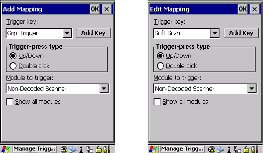
Chapter 5: Configuration
Manage Triggers
Psion Teklogix 7545 Hand-Held Computer User Manual 115
Show All Modules
By default, the trigger mapping list only shows active mappings. Mappings for drivers or
applications that are not currently active are not normally displayed. By checking this
checkbox, all mappings, both active and inactive, are displayed.
Add
Tapping this button brings up the Add Mapping dialog (see page 115), so that you can add
new trigger mappings.
Edit
Tapping this button brings up the Edit Mapping dialog (see page 115), so that you can edit
existing trigger mappings.
Remove
Tapping this button removes an existing mapping.
OK
The OK button in the top right of the Manage Triggers screen saves all changes made. If the
cancel button X is tapped instead, or the [ESC] key is pressed, all changes made will
be discarded.
5.6.6.2 Add And Edit Trigger Mapping
These dialogs allow you to add and edit trigger mappings.
Preliminary Draft 3
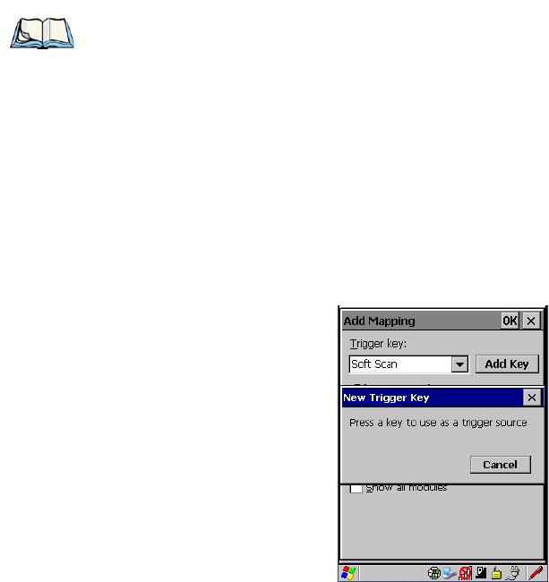
Chapter 5: Configuration
Manage Triggers
116 Psion Teklogix 7545 Hand-Held Computer User Manual
Trigg er Key
This drop-down list allows you to specify the source of the trigger events, such as the Soft
Scan, Left Scan, etc., for the trigger module selected.
Add Key
Only existing trigger sources are shown in the Source combo-box. To add a new source to
this list, tap on the Add Key button. A dialog will pop up and allow you to select the key-
board key to use as a trigger source.
Trigger-Press Type
You can enable either an Up/Down or Double Click response to a trigger press. Normally,
when a trigger (keyboard key, etc.) is pressed and released, a “trigger down” event is sent to
the “owner”—that is, the application receiving the trigger press information—followed by a
“trigger up”. If Double Click is chosen in this menu, when the trigger is pressed, released,
and then pressed again, a “double-click” event will have occurred. If a mapping with the
type Up/Down has also been configured for the same source, it will only receive the first set
of trigger events.
Note: It is possible to map the same source to different modules (trigger consumers)—for
example, to both the Imager and Non-Decoded Scanner. If so, both devices/opera-
tions will occur simultaneously. This is not recommended in most cases, especially
with devices such as Imagers or RFID Readers.
It is also possible to map different sources to the same module (trigger con-
sumer)—for example, two different trigger keys can be mapped to the RFID
File System.
Preliminary Draft 3
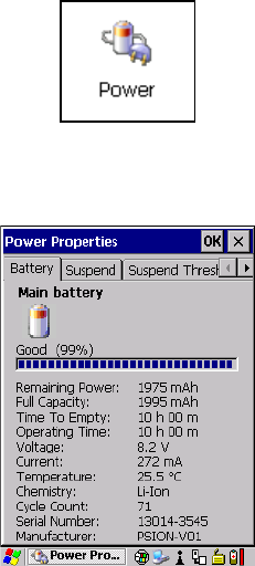
Chapter 5: Configuration
Power Management Properties
Psion Teklogix 7545 Hand-Held Computer User Manual 117
Module Trigger
This identifies the driver or application receiving the trigger presses.
Show All Modules
By default, inactive owners are not shown. By checking this checkbox, all owners, both
active and inactive, are displayed.
5.6.7 Power Management Properties
This icon displays a Power Properties dialog box that indicates the unit’s battery capacity
and allows you to manage battery use.
•In the Control Panel, choose the Power icon.
5.6.7.1 Battery Capacity
•In the Power Properties dialog box, open the Battery tab to view battery details.
Preliminary Draft 3
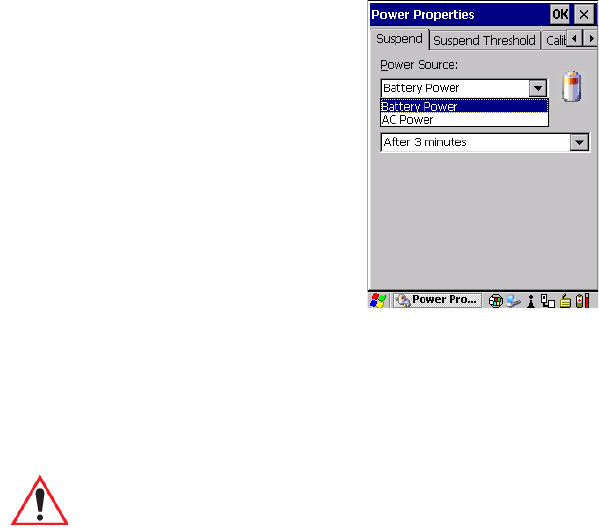
Chapter 5: Configuration
Power Management Properties
118 Psion Teklogix 7545 Hand-Held Computer User Manual
5.6.7.2 Power Saving Suspend
•In the Power Properties dialog box, open the Suspend tab.
Power Source
This drop-down menu allows you to specify whether the unit is using AC Power or
Battery Power.
Suspend Timeout
When the 7545 is idle—not receiving any user input (a key touch, a scan, and so on) or
system activity (serial data, an activity initiated by an application, and so on)—the hand-
held uses the value assigned in the Suspend Timeout field to determine when the unit will go
to sleep (appear to be off).
When the time in the Suspend Timeout field elapses without any activity, the unit enters
suspend state. In suspend state, the 7545 CPU enters a sleep state, and the radio is shut off.
The state of the device (RAM contents) is preserved. Pressing [ENTER] wakes the system
from suspend state. When the 7545 is in suspend state, the network connection will not be
broken immediately. If the connection is dropped, you must re-establish the network
connection.
Important: Psion Teklogix recommends setting the Suspend value to 10 minutes. To
further reduce power consumption, carefully consider the duration of time
that the display backlight is ‘on’ (see “Backlight” on page 99).
Preliminary Draft 3
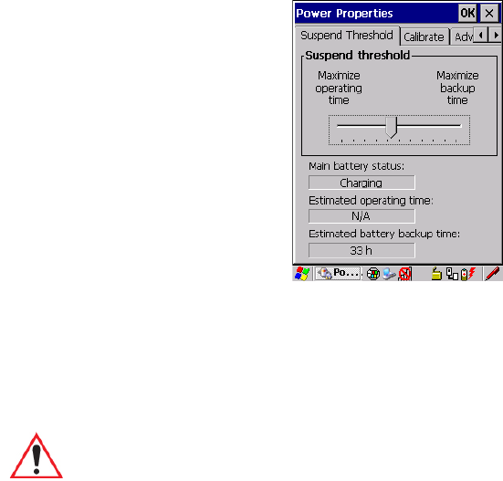
Chapter 5: Configuration
Power Management Properties
Psion Teklogix 7545 Hand-Held Computer User Manual 119
5.6.7.3 Suspend Threshold And Estimated Battery Backup
The Suspend Threshold adjustment tells the system when to shut down when the battery
drains. If you choose Maximum Operating Time, the unit will run until the battery is com-
pletely empty; the RAM is only backed up for a short period of time. If you choose
Maximum Backup Time, the hand-held shuts off with more energy left in the battery so
RAM can be backed up for a longer period of time.
The Estimated Battery Backup is the amount of battery power that has been reserved or set
aside to protect data until a charged battery can be installed in the 7545. When the battery
capacity is depleted up to the Estimated Battery Backup reserve specified in the Suspend
Threshold menu, the 7545 shuts off automatically and uses the reserve power to preserve the
Important: Selecting Maximum backup time will reserve approximately 20% of the
battery capacity for memory backup. Once the battery is drained, the system
RAM memory is lost and the unit must cold boot.
In most real-time transaction environments this is not a problem (it only
takes a few seconds to cold boot). Batch transaction environments, where
data is not saved to a non-volatile memory (such as an SD FLASH card),
may need to pay particular attention to this parameter. Psion Teklogix does
not recommend the storage of any valuable data in system RAM.
The 7545 Windows CE 5.0 environment does not store any critical data in
RAM (such as the registry or file system).
If your application does not save data to RAM, Psion Teklogix recommends
keeping the Suspend Threshold setting as low as possible to maximize
battery run time.
Preliminary Draft 3
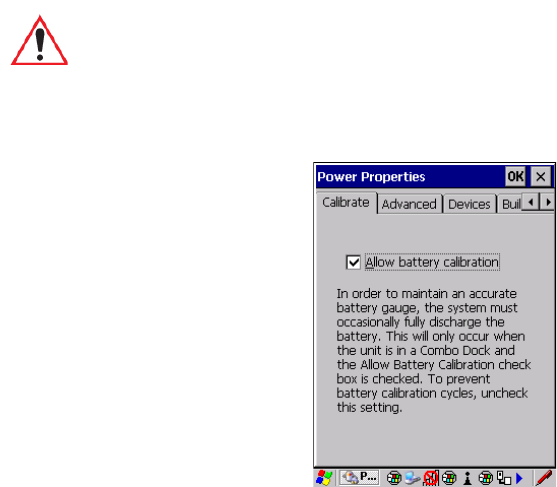
Chapter 5: Configuration
Power Management Properties
120 Psion Teklogix 7545 Hand-Held Computer User Manual
data stored on the computer. Once the 7545 shuts down, it cannot be switched on until a
fresh battery is installed, or the unit is inserted in a docking station or cradle.
•Slide the Suspend Threshold button to the right to increase the battery capacity
reserved for backup purposes. Data will be preserved to a maximum of 124 hours.
•Slide the Suspend Threshold button to the left to decrease the power reserved for
backup purposes; this increases the 7545 operating time—the amount of time the unit
will operate before shutting down—but reduces the power reserved for backup purposes
to a minimum of 24 hours.
Internal super-capacitors will protect the data stored in the 7545 while the battery is
swapped for a fully charged one.
5.6.7.4 Calibrate
Tapping in the checkbox next to Allow Battery Calibration allows the battery to be recali-
brated only when necessary if the unit is inserted in a Combo Docking station.
Important: Once the battery is removed, the super-capacitors will preserve the data
stored on the 7545 for approximately 5 minutes. It is critical that you install
a charged battery before this time elapses.
Preliminary Draft 3
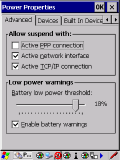
Chapter 5: Configuration
Power Management Properties
Psion Teklogix 7545 Hand-Held Computer User Manual 121
5.6.7.5 Advanced
Allow Suspend With:
This tab allows you to specify whether or not your unit will enter Suspend state while it is
operating with an active PPP connection, network interface, or active TCP/IP connection.
Low Power Warnings
The sliding scale at the bottom of this tab allows you to specify the remaining battery capac-
ity at which a warning message is displayed on the 7545 screen, from 0% to 20%.
Preliminary Draft 3
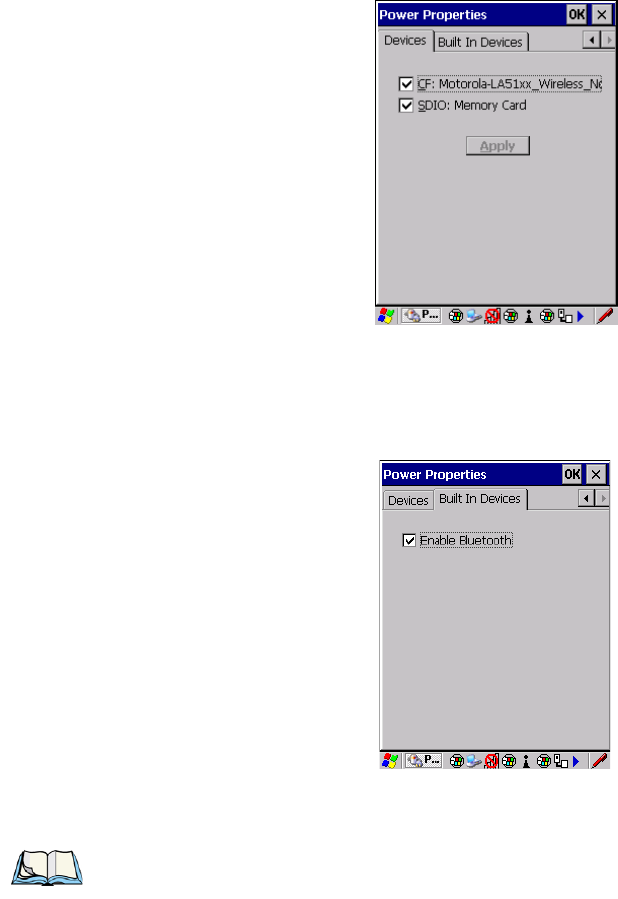
Chapter 5: Configuration
Stylus Properties
122 Psion Teklogix 7545 Hand-Held Computer User Manual
5.6.7.6 Devices
This tab controls power to individual CF and SDIO slots. Enable or disable the checkboxes
as needed, then tap on OK to save your changes.
5.6.7.7 Built In Devices
This tab controls power to built-in devices such as Bluetooth. Enable or disable the check-
boxes as needed, then tap on OK to save your changes.
5.6.8 Stylus Properties
Note: Touchscreen calibration may not be enabled on your unit. If your screen appears to
require recalibration, contact your supervisor.
Preliminary Draft 3
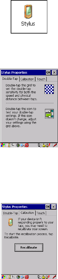
Chapter 5: Configuration
Stylus Properties
Psion Teklogix 7545 Hand-Held Computer User Manual 123
•In the Control Panel, choose the Stylus icon.
5.6.8.1 Double-Tap
•In the Double-Tap menu, follow the directions to tailor the sensitivity of the stylus when
you tap on the touchscreen.
5.6.8.2 Calibration
Touchscreens rarely require recalibration. However, if your touchscreen has never been cal-
ibrated or if you find that the stylus pointer is not accurate when you tap on an item, follow
the directions below.
• Choose the Calibration tab, and then tap on the Recalibrate button.
• Follow the directions in the Calibration tab to recalibrate the screen.
Preliminary Draft 3
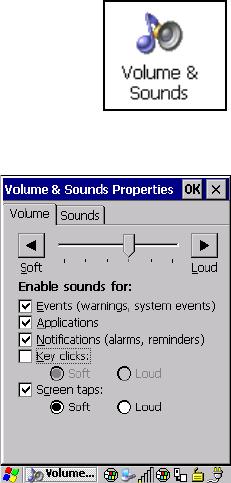
Chapter 5: Configuration
Volume And Sounds Properties
124 Psion Teklogix 7545 Hand-Held Computer User Manual
5.6.8.3 Touch
This tab allows you to disable the touchscreen.
• Choose the Touch tab. Select the checkbox next to Disable the touch panel.
5.6.9 Volume And Sounds Properties
•In the Control Panel, choose the Volume & Sounds icon.
5.6.9.1 Volume Adjustments
• Slide the volume button to the left to lower the beeper volume or to the right to increase
the beeper volume.
• Under the heading Enable sounds for, enable the conditions under which you want the
7545 to emit a beep.
5.6.9.2 Sound Adjustments
The 7545 computer is equipped with a beeper rather than a sound port. The options under
this tab are not available for this hand-held.
5.7 Bluetooth Setup
Bluetooth is a global standard for wireless connectivity for digital devices and is intended
for Personal Area Networks (PAN). The technology is based on a short-range radio link that
Preliminary Draft 3
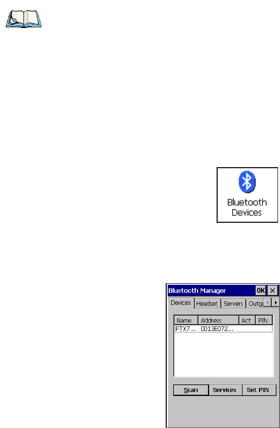
Chapter 5: Configuration
Devices
Psion Teklogix 7545 Hand-Held Computer User Manual 125
operates in the ISM band at 2.4 GHz. Because Bluetooth utilizes a radio-based link, it does
not require a line-of-sight connection in order to communicate.
The Bluetooth radio is disabled by default. Before you begin the setup process:
•In the Control Panel, tap on the Power icon.
• Tap on the Built In Devices tab, and tap in the checkbox next to Enable Bluetooth. Tap
on OK.
When the radio is enabled, a Bluetooth icon appears the taskbar at the bottom of the screen.
It is ready for setup.
•In the Control Panel, choose the Bluetooth Devices icon to display the Bluetooth
Manager screen.
The Bluetooth Manager dialog box displays the other Bluetooth devices with which you
can communicate.
5.7.1 Devices
If you intend to pair devices (a scanner or printer for example), power on and bring the
devices within 5 m (16.4 ft.) of the 7545 before proceeding with the discovery process de-
scribed below.
Note: The Bluetooth radio uses an internal antenna.
Preliminary Draft 3
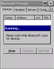
Chapter 5: Configuration
Devices
126 Psion Teklogix 7545 Hand-Held Computer User Manual
Pairing A Device
To pair devices:
• Follow the manufacturer’s instructions to place the device you want to pair in
pairing mode
• Choose the Devices tab and Scan for devices in your area.
• When the scan is complete, highlight the device you want to pair with and either double-
click or press the Services button.
• If a PIN dialog box appears, type your PIN and tap on OK.
After entering the device PIN number, the Services dialog appears with a list of services
available on that device.
• To select a service, double-click on the service you want, or highlight the service and
press the space bar.
• In the drop-down list of options available, choose Active to pair the device.
A COM/BSP port name will appear next to the service for this device. Your device is
now paired.
Scan
•Click on the Scan button to list available devices.
Wait for the 7545 to complete its scan (approximately 20 seconds). When scanning starts,
the Scan button will change to Stop—if necessary, you can tap on this button to stop the pro-
cess. Once scanning is complete, all discovered devices will be displayed in the list box,
with Name, Address, Active status, and PIN information.
Preliminary Draft 3

Chapter 5: Configuration
Devices
Psion Teklogix 7545 Hand-Held Computer User Manual 127
The Active column indicates whether any service is activated for that device. When a service
is activated, the device is displayed in the list even when it is not detected during the scan.
The PIN column indicates whether you have a PIN (password) set for the device.
At this point you can either query for services or set the PIN for each device. Once you high-
light a device in the list box, both the Services and Set PIN buttons become available.
Services
A discovered device may display several service profiles that it can use to communicate, and
you will want to activate the type you need. Supported profiles that can be activated include:
DUN (Dial-Up Networking service), Printer (serial service), and LANPPP (LANAccessUs-
ingPPP service). ASync (ActiveSync) is another available profile.
• To start the service scan, highlight a device in the Devices menu list, and then click on
the Services button or double-click on the device entry.
Once the device’s service profiles are displayed in the Services list box:
• Highlight the service to be activated.
• Press [SPACE] or right-click to display the Activation menu.
The Activation menu contains four options: Activate, Authenticate, Outgoing, and Encrypt.
Once the service is successfully activated, the assigned port (if applicable) will appear in the
Port column of the Services list box. You can choose to use BSP or COM as the port name.
BSP is the latest Microsoft Bluetooth stack standard, but older applications assume serial
ports are COM. When using COM as the port name, the Bluetooth manager will try to find
and use a free port between COM7 and COM9. When using BSP as the port name, BSP2 to
BSP9 are available for use. The port is available as soon as it is activated.
Note: During the scanning process, addresses are located first, followed by names. Only
the names of devices that are within the Bluetooth radio coverage range will
be retrieved.
Note: If the remote device is out of reach or turned off, it can take a considerable amount
of time for the Services dialog box to appear—it may appear to be frozen.
Note: The CH column shows the RFCOMM channel of the service if the service is
RFCOMM-based. This information is not generally needed except for
debugging purposes.
Preliminary Draft 3

Chapter 5: Configuration
Devices
128 Psion Teklogix 7545 Hand-Held Computer User Manual
To add a service to the Outgoing port, an active service must first be deactivated. Then you
can choose the Outgoing option from the Activation menu (highlight a service, right-click
or press the [SPACE] bar to display the Activation menu).
The Authentication and Encryption options can be changed only before activation. To
change these after activation, deactivate the service first, then change the options.
Once a service is activated, all the information regarding the service, including the
RFCOMM channel number, is saved in the registry. (Some remote devices may change their
RFCOMM channel numbers when they reboot, so your saved setting may not work when
the remote device is rebooted. In that case, you must deactivate the service and reactivate it
to detect the current RFCOMM channel.)
Set PIN
PINs can be set for each device by pressing the Set PIN button in the Devices menu, or you
can skip this step and try to connect to the device first.
• Highlight a device, click on the Set Pin button, and type the PIN.
You will receive a message, either that the PIN has been successfully validated or that it has
been rejected.
If the PIN has been validated, an asterisk (*) appears in the PIN column in the Devices list
box, indicating that this device has a PIN set. Once a PIN is entered, it is saved in
the registry.
To remove the PIN:
• Choose Set PIN, and press [ENTER].
If the 7545 attempts to connect to a remote device that has Authentication enabled and does
not have a required PIN set, an Authentication Request dialog box appears.
• Enter the PIN, and tap on OK to connect the devices.
Important: The remote device must have authentication enabled, otherwise the PIN
authentication will fail.
Preliminary Draft 3
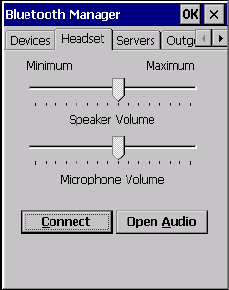
Chapter 5: Configuration
Headset
Psion Teklogix 7545 Hand-Held Computer User Manual 129
5.7.2 Headset
To pair a headset with your 7545:
• Place your headset in Discoverable mode. You can do this by following the manufac-
turer’s instructions in your headset’s user guide.
• Search and discover your headset. Choose the Devices tab in Bluetooth Manager and
scan for devices in your area. (Note that if this is your first time pairing, the device scan
occurs automatically—you do not need to tap on the Scan button to perform a scan.)
When the scan is complete, a list of discovered devices is listed.
• Search for your device’s services. You can do this by double-clicking on the headset or
you can highlight headset and tap on the Services button.
• If the headset has authentication enabled, a dialog box appears requesting that you enter
a PIN number. Enter the PIN number and tap on OK.
• Select a service to which you want to connect. You can do this by pressing and holding
the stylus over the desired service. Once the pop-up menu has appeared, choose Active.
Your headset is now paired. A COM/BSP port name will now appear beside the service for
this device. An asterisk will appear under the Active list in the Services screen.
Connect
Tap on Connect to establish a data connection between the 7545 and the Bluetooth headset.
Open Audio
Tap on Open Audio to establish the audio connection between the 7545 and the
Bluetooth headset. The headset is then able to change the volume of the speaker and micro-
phone on the computer. In order to open the audio streams, you will first have to Connect.
Preliminary Draft 3
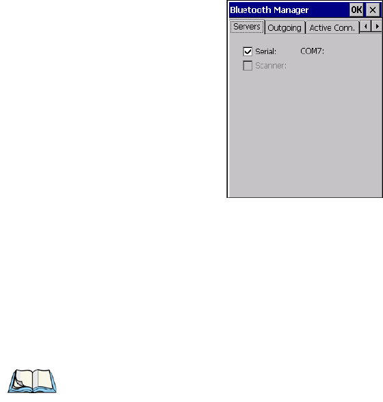
Chapter 5: Configuration
Servers
130 Psion Teklogix 7545 Hand-Held Computer User Manual
5.7.3 Servers
When the Bluetooth connection is initiated from your 7545 to the remote device, the 7545 is
called the ‘client’ and the remote is called the ‘server’. The Servers menu displays the server
profiles that can be activated in your 7545. There are currently two server profiles available:
Serial and Scanner.
• Tap on the checkbox to activate the server, and it will display the associated port name
beside the server name.
Once you activate a server profile, it is recommended that the 7545 be rebooted before you
try to bond from a server.
Note: You do not need to reboot if you are deactivating a server.
Preliminary Draft 3
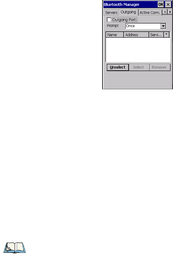
Chapter 5: Configuration
Outgoing
Psion Teklogix 7545 Hand-Held Computer User Manual 131
5.7.4 Outgoing
Outgoing Port acts as a serial port that can be used to connect to a list of Bluetooth devices
(one at a time), but you have the freedom to switch on-the-fly.
The Outgoing Port checkbox allows you to create the Outgoing port. When the port is cre-
ated, the Outgoing tab lists the port name.
The Outgoing list dialog box displays a list of services marked as ‘Outgoing’. The * column
indicates the currently selected service. You can tap on Unselect to reset the current selec-
tion, or you can tap on Select to make a selection. The Remove button deletes the service
from the outgoing list.
The Prompt menu determines the behaviour of the pop-up Selection menu. Choosing Every-
time causes the Selection menu to be displayed each time an outgoing port is created. If you
choose Once, the menu is displayed only when a partner service is not selected.
To display the Selection menu at any time:
• Press [CTRL] [ALT] [F1], and switch the partner Bluetooth device.
If a connection to a partner device already exists, the connection is dropped and another con-
nection to the newly selected device is created instantly without disrupting the application
that has opened the outgoing port.
Note: To add a service to the Outgoing port, an active service must first be deactivated.
Then you can choose the ‘Outgoing’ option from the Activation menu (highlight a
service, right-click or press the [SPACE] bar to display the Activation menu).
Preliminary Draft 3
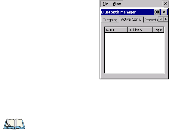
Chapter 5: Configuration
Active Conn.
132 Psion Teklogix 7545 Hand-Held Computer User Manual
5.7.5 Active Conn.
The Active Conn. menu lists the Name, Address, and Type of the currently active connec-
tions. The table is periodically updated, but it can take a few seconds before it reflects the
actual list of connections. The Type column of the table shows ‘ACL’ or ‘SCO’. The Con-
nection list table shows the connections for scanning as well as the service connections.
Note: You can change the device-name and description of your radio by clicking on the
System icon in Control Panel, which will open the System Properties dialog box.
Click on the Device Name tab to access the menu and change your settings. Then
click on OK.
Although the name will have changed in the Properties menu in Bluetooth Controls,
the radio only reads it on boot-up. For the changes to take effect, you must cold
reset the 7545 (for cold reset instructions, see “Cold Reset” on page 35).
Preliminary Draft 3
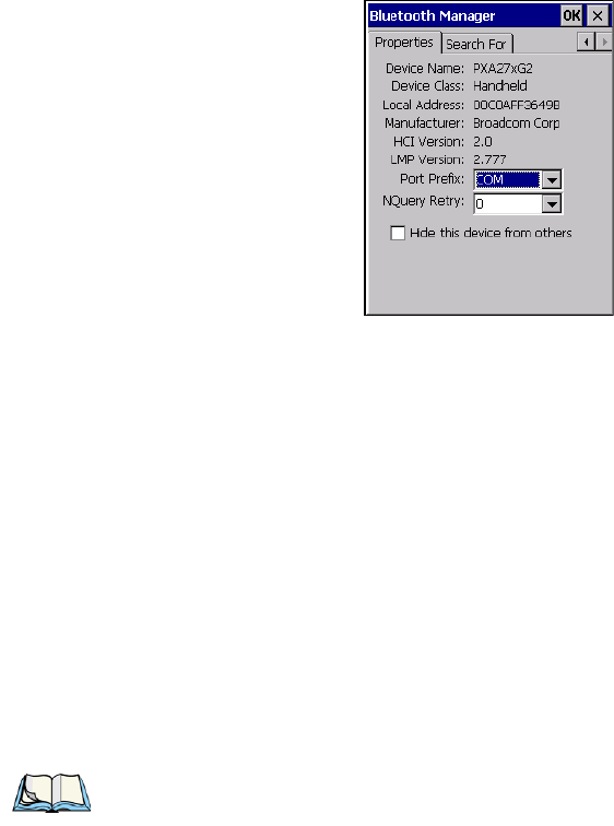
Chapter 5: Configuration
Properties
Psion Teklogix 7545 Hand-Held Computer User Manual 133
5.7.6 Properties
The Properties menu displays information about your 7545, and provides some
port options.
The Device Name field shows the device name of your 7545. This name can be changed (see
the Note on the previous page for details).
Device Class shows the Class of Device (e.g. desktop, hand-held), which is always set to
Handheld.
Local Bluetooth Address shows the address of your 7545 radio.
Port Prefix is used to set the port name to either BSP or COM. When the name is set to BSP,
BSP2 to BSP9 are available for activated services (including the server). When COM is
chosen, COM7 to COM9 are available.
NQuery Retry (Name Query Retry) governs the number of times the hand-held will attempt
to query the names of other Bluetooth devices if the first attempt fails. (When the 7545 scans
for other devices, it sometimes fails to scan names.)
The option Hide this device from others prevents other devices from connecting to
your 7545.
Note: Keep in mind that setting this parameter to a higher value will lengthen the
scan time.
Preliminary Draft 3

Chapter 5: Configuration
Search For
134 Psion Teklogix 7545 Hand-Held Computer User Manual
5.7.7 Search For
The Search For menu allows you to specify the services for which the Bluetooth radio
will scan.
5.8 Error Reporting
Error Reporting allows you to enable or disable Microsoft error reporting prompts.
• Tap on Start>Settings>Control Panel>Error Reporting icon to access your options.
5.9 IPv6 Support
The IPv6 Support icon in the Control Panel allows you to activate IPv6 network support on
your unit if your network setup requires this. This internet protocol specification (version 6)
supports 128-bit IP addresses, replacing version 4.
Preliminary Draft 3
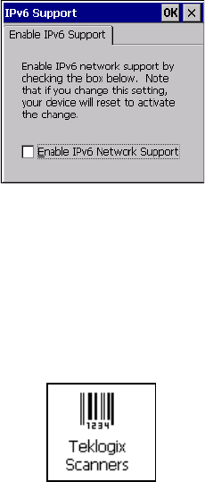
Chapter 5: Configuration
Scanner Settings
Psion Teklogix 7545 Hand-Held Computer User Manual 135
• Choose the IPv6 Support icon to display the associated dialog box.
• Choose the checkbox next to Enable IPv6 Network Support to enable this
internet protocol.
5.10 Scanner Settings
The Teklogix Scanners icon in the Control Panel provides dialog boxes in which you can
tailor bar code options and choose the bar codes your scanner will recognize. The parame-
ters are preset with the default settings of the decoded scanner installed in the unit.
For a listing of available scanners and their specifications, please refer to Chapter 7:
“Specifications”.
Preliminary Draft 3
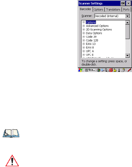
Chapter 5: Configuration
Bar Codes
136 Psion Teklogix 7545 Hand-Held Computer User Manual
5.10.1 Bar Codes
5.10.1.1 Scanner
The drop-down menu to the right of the Scanner option allows you to choose configurations
for one of the following scanner types, depending on what is installed in/on your hand-held:
Decoded (internal), Decoded (Intermec ISCP), Imager and Non-decoded.
The symbologies listed in the Barcodes tab change to reflect the scanner you choose and the
bar codes it supports. Always defer to your bar code scanner’s programming manual when
in doubt about the availability or settings for any parameter.
Keep in mind that some bar code types are only available when an internal imaging scanner
is installed. All internal scanners can be configured using these dialog boxes. External, non-
decoded scanners are also configured through the Scanner Properties dialog box.
However, external decoded scanners must be configured by scanning special configuration
bar codes. In these cases, the scanner manufacturer provides programming manuals for con-
figuration purposes.
Note: Your 7545 comes preconfigured from the factory for internal scanner types. The
type of scanner installed can be determined from the System icon in the Control
Panel, under the System Properties tab.
Important: To improve the decode speed and performance, enable (set to ‘on’) only
those codes that are required by the application.
For information on configuring the bar code symbologies, see Appendix C:
“Bar Code Settings”.
Preliminary Draft 3
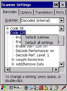
Psion Teklogix 7545 Hand-Held Computer User Manual 137
Chapter 5: Configuration
Bar Codes
Restoring Default Settings
• For the Symbol LS3408 decoded scanner, refer to the programming guide supplied with
your scanner.
• For PowerScan® (PSC) decoded scanners, refer to the PowerScan Programming
Guide.
5.10.1.2 Restoring Default Settings
If you want to restore the factory defaults after making changes, the defaults can be applied
to a selected parameter, sub-tree of parameters or all scanner parameters.
• Press and hold the stylus on a symbology (e.g., Code 128) to display a pop up a menu.
• Choose Default subtree to reset only the parameters in the symbology you selected, or
choose Default all settings to reset all scanner parameters to default settings.
To reset a single parameter to its default setting:
Preliminary Draft 3
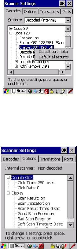
Chapter 5: Configuration
Options
138 Psion Teklogix 7545 Hand-Held Computer User Manual
• Press and hold the stylus on the parameter you want to reset.
• Choose Default parameter to reset the parameter to the default setting.
5.10.2 Options
This tab allows you to tailor the double-click parameters and the display options associated
with your scanner.
5.10.2.1 Double Click Parameters
Click Time (msec)
This parameter controls the maximum gap time (in milliseconds) for a double-click. If the
time between the first and second clicks of the scanner trigger is within this time, it is con-
Preliminary Draft 3

Chapter 5: Configuration
Options
Psion Teklogix 7545 Hand-Held Computer User Manual 139
sidered a double-click. The allowable range is 0 to 1000. A value of zero disables this
feature.
A double-click produces different results depending on whether or not a value is assigned in
the “Click Data” parameter. When a value is not assigned for the “Click Data”, double-click-
ing the scanner trigger overrides the target dot delay set in the “Dot Time” parameter and
initiates a normal scan sweep. If a value is assigned for the “Click Data” parameter, double-
clicking the scanner trigger inserts the “Click Data” value rather than initiating a scan.
Click Data
For both integrated and external scanners, this parameter determines which character is sent
to the application installed in your 7545 following a double-click. A dialog box appears,
asking that you press the key you want to insert. The ASCII/Unicode key value of the key-
press is displayed.
Pressing the [ESC] key in this dialog box resets the data to zero.
5.10.2.2 Display Parameters
Scan Result
When this parameter is enabled, the type of bar code and the result of the scan appear on the
screen. Note that this information is only displayed after a successful decode and is visible
only while the scanner trigger is pressed. When the trigger is released, this information is
cleared from the screen.
Scan Indicator
When this parameter is enabled, the laser warning logo appears on the display whenever the
scanner is activated.
Scan Result Time (sec)
The value assigned to the Scan Result Time parameter determines how long the scan results
of a successful scan are displayed on the screen. Time is measured in seconds, and a value of
0 (zero) disables the parameter. When you choose this option, a dialog box appears where
you can enter a value.
Note: To remove the scan result from the screen before the “Result Time” has expired,
point the scanner away from the bar code and press the trigger.
Preliminary Draft 3
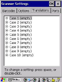
Chapter 5: Configuration
Translations
140 Psion Teklogix 7545 Hand-Held Computer User Manual
Good Scan Beep And Bad Scan Beep
These parameters determine whether or not the 7545 emits an audible scanner ‘beep’ when a
good (successful) scan or a bad (unsuccessful) scan is performed. Set these parameters to
either on to enable the beeper or off to disable it.
Soft Scan Timeout
This parameter is used by the SDK “Scan” function (soft-scan: starting a scan session via the
SDK function, instead of a physical user trigger press). The value assigned to this parameter
determines the soft-scan timeout from 1 to 10 sec (default is 3 sec).
Scan Log File
If this parameter is enabled, the input bar code and the modified/translated output bar code
are logged in the file \Flash Disk\ScanLog.txt. Keep in mind that if Scan Log File is enabled,
there is a slight performance reduction when performing multiple scans since the log file is
written to persistent storage.
5.10.3 Translations
The Translations menu allows you to define up to 10 cases, each consisting of up to 10 rules
in sequential order. Only one case will be applied to a bar code and a case will only be
applied if all rules specified in the case are successful—if a rule within a case fails, the entire
case fails.
Preliminary Draft 3
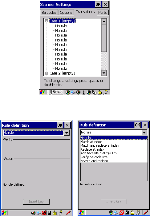
Chapter 5: Configuration
Tr a n s l a ti o n s
Psion Teklogix 7545 Hand-Held Computer User Manual 141
•In the Translation menu, tap on the Case # to create rules.
• Tap on the No rule drop-down menu to display the rules.
Preliminary Draft 3
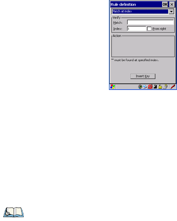
Chapter 5: Configuration
Translations
142 Psion Teklogix 7545 Hand-Held Computer User Manual
When you choose a rule, an associated screen is displayed in which you can define the rule.
5.10.3.1 Case Rules
The case rules are defined as follows:
•No rule—ignored.
•Search and replace—replaces all instances of the match string. (Note that this rule
cannot fail.)
•Match at index—matches the match string at a specified index.
•Match and replace at index—matches the match string at a specified index and
replaces/changes it.
•Replace at index—replaces/changes unspecified data in a given range.
•Add barcode prefix/suffix—adds a global prefix or suffix.
•Verify barcode size—verifies the bar code size. This rule should generally be assigned
first, before creating subsequent rules.
Translation information about the status of each case/rule is displayed in the scan log file
(see “Scan Log File” on page 140) when enabled. This is useful if a case fails, and you are
trying to determine why a rule is failing.
Note: Keep in mind that the effects of previously applied rules must be taken into account
when creating subsequent rules. For example, if the bar code size is important, it
should be checked before any rules that might change the size are applied.
Preliminary Draft 3
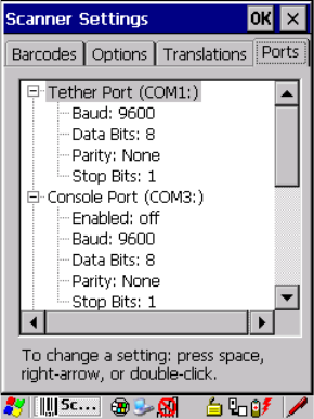
Chapter 5: Configuration
Ports
Psion Teklogix 7545 Hand-Held Computer User Manual 143
5.10.4 Ports
Figure 5.4 Tether, Console, and Port Replicator Port Settings
While you cannot configure the scanner, you can configure communications with a serial
decoded scanner using the options in this tab.
Use these settings to ensure that the communication ports on the 7545 match the settings of
the serial devices to which they are connected. If the settings do not match exactly, the
devices may not function. Note that some devices can auto-detect serial port settings (such
as baud rate), and in this case the 7545 will dictate the settings. Baud rates often have a
direct impact on performance—they should be set as high as possible while still ensuring re-
liable communication.
Preliminary Draft 3
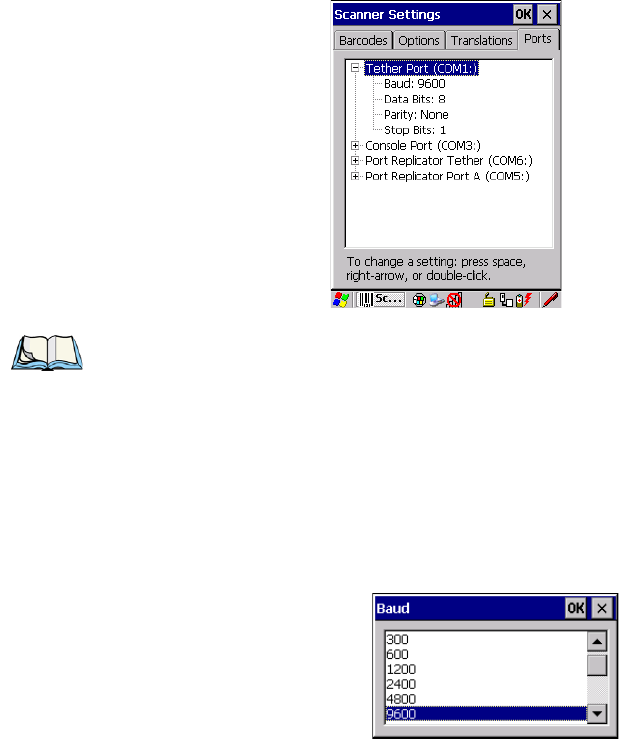
Chapter 5: Configuration
Ports
144 Psion Teklogix 7545 Hand-Held Computer User Manual
5.10.4.1 Tether Port (COM1)
Baud
Double-tapping on this parameter displays a pop-up window in which you can choose an ap-
propriate rate of data transfer.
Figure 5.5 Tether Port Baud Rates
Data Bits
This parameter determines the number of data bits included in each asynchronous data byte.
Most devices use 8-bit data bytes. Double-tapping on this option displays a pop-up window
in which you can choose either 7 or 8 data bits.
Note: RS-232 serial communication is one of the modes available on the tether port,
located on the side of the 7545.
These parameters refer only to external decoded scanner communications. They
have no effect if the generic serial device tether cable is plugged in.
Preliminary Draft 3
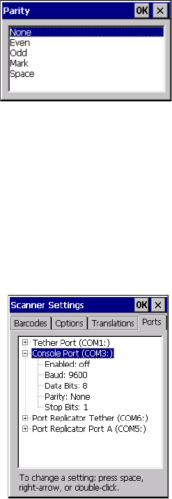
Chapter 5: Configuration
Ports
Psion Teklogix 7545 Hand-Held Computer User Manual 145
Parity
This parameter determines the type of parity checking used on the data going through the
tether port. Double-tapping on this option displays a pop-up window in which you can
choose the appropriate Parity.
Stop Bits
This parameter specifies the number of stop bits—1, 1.5 or 2—used for asynchronous
communication.
5.10.4.2 Console Port (COM3)
The console port is accessed via the docking connector on the bottom of the 7545. Only the
Portable Docking Module (PDM) provides access to the console port through a DE-9
interface.
Figure 5.6 Console Port Settings
Enabled
This parameter must be set to on in order for the 7545 to recognize the attached device as a
decoded bar code scanner.
Baud
Refer to page 144 for details.
Preliminary Draft 3
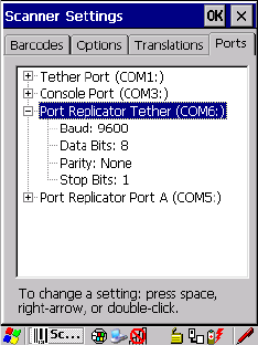
Chapter 5: Configuration
Ports
146 Psion Teklogix 7545 Hand-Held Computer User Manual
Data Bits
Refer to page 144 for details about this parameter.
Parity
For details, refer to page 145.
Stop Bits
Refer to page 145 for details about Stop Bits.
5.10.4.3 Port Replicator Tether (COM6)
The port replicator tether is a duplicate tether port located on the port replicator module of
the 7545 cradles.
Figure 5.7 Port Replicator Tether Settings
Baud
Refer to page 144 for details.
Data Bits
Refer to page 144 for details about this parameter.
Parity
For details, refer to page 145.
Stop Bits
Refer to page 145 for details about Stop Bits.
Preliminary Draft 3
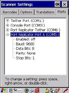
Chapter 5: Configuration
Ports
Psion Teklogix 7545 Hand-Held Computer User Manual 147
5.10.4.4 Port Replicator Port A (COM5)
Port Replicator Port A(COM5) is the standard RS-232 DE-9 DTE port on the 7545 port rep-
licator module, available on certain cradle types.
Enabled
This parameter must be set to ON in order for the 7545 to recognize the device connected to
the Port Replicator 9-pin (COM5).
Baud
Refer to page 144 for details.
Data Bits
Refer to page 144 for details about this parameter.
Parity
For details, refer to page 145.
Stop Bits
Refer to page 145 for details about Stop Bits.
Preliminary Draft 3
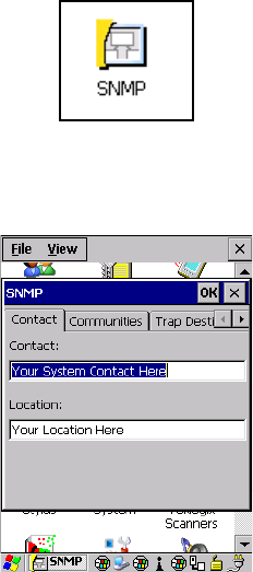
Chapter 5: Configuration
SNMP (Simple Network Management Protocol) Setup
148 Psion Teklogix 7545 Hand-Held Computer User Manual
5.11 SNMP (Simple Network Management Protocol) Setup
Simple Network Management Protocol (SNMP) is the protocol used to monitor and manage
devices attached to a TCP/IP network (providing they support SNMP).
SNMP uses Management Information Bases (MIBs) that define the variables an SNMP
Network Management Station can access. Each product has a defined set of MIBs that deter-
mine how SNMP operates, the type of access allowed and so on.
All Psion Teklogix products support the TEKLOGIX-GENERIC-MIB—a MIB that defines
some common features across Psion Teklogix products.
All devices also support MIB-II, a management information base that defines the common
features of TCP/IP networks. The SNMP Agent software embedded in the 7545 product
supports SNMPv1 (RFC 1157).
•In the Control Panel, choose the SNMP icon.
5.11.1 Contact
The SNMP dialog box is displayed.
Preliminary Draft 3
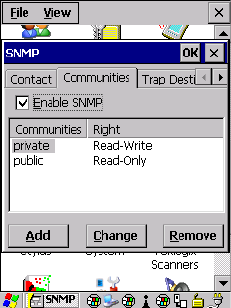
Chapter 5: Configuration
Communities
Psion Teklogix 7545 Hand-Held Computer User Manual 149
Contact
This field identifies the contact person for this managed node along with information about
how to get in touch with this person. The content of this parameter is accessible through
MIB-II’s sysContact object.
Location
This parameter is used to identify the physical location of this node (e.g., Warehouse A:
Pillar 32B). The content of this parameter is accessible through MIB-II’s sysLocation object.
5.11.2 Communities
The Communities tab allows you to limit access to SNMP-managed devices to those SNMP
Managers with matching “community names”, as specified by RFC 1157.
Enable SNMP
Tapping the checkbox Enable SNMP allows the device to respond to SNMP queries and to
send Traps. After enabling this option and rebooting the device, the SNMP Agent will auto-
matically start up. To disable this feature, remove the checkmark from the checkbox.
Preliminary Draft 3
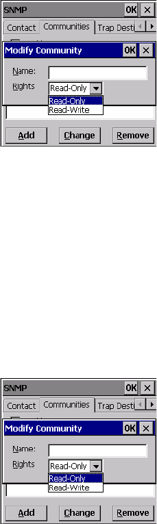
Chapter 5: Configuration
Communities
150 Psion Teklogix 7545 Hand-Held Computer User Manual
5.11.2.1 Adding A Community
• Choose the Add button to add a new ‘community’.
Name
The value assigned here is the name assigned by the network administrator to the set of
devices to which this managed node belongs.
Rights
This menu allows you to specify access, that is, ‘Read-Only’ or Read-Write’
5.11.2.2 Modifying A Community Setting
To modify an existing community:
• Highlight the community you want to alter.
• Choose the Change button.
A Modify Community dialog box is displayed, listing the community you highlighted.
•Edit the Name and/or Rights, and press [ENTER] to save your changes.
5.11.2.3 Removing An Existing Community
To remove an item:
Preliminary Draft 3
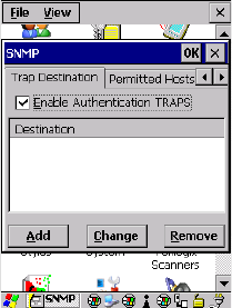
Chapter 5: Configuration
Trap Destination
Psion Teklogix 7545 Hand-Held Computer User Manual 151
• Highlight the community you want to remove in the Communities tab and then choose
the Remove button.
A Delete Confirmation screen is displayed.
• To remove a community, choose the Ye s button, or
If you decide not to remove the community, choose the No button.
5.11.3 Trap Destination
A trap is an unsolicited report sent to SNMP Managers by the SNMP Agent running on the
managed node. This option allows you to define where the report will be sent.
5.11.3.1 Enabling Authentication TRAPS
Enabling Enable Authentication TRAPS allows authorization traps to be sent when a failure
is detected (e.g., an SNMP message received with a bad community name).
5.11.3.2 Adding A Destination
To add a new destination:
Preliminary Draft 3
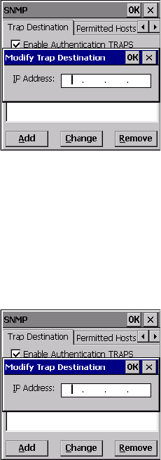
Chapter 5: Configuration
Tra p De s tinati on
152 Psion Teklogix 7545 Hand-Held Computer User Manual
• Choose the Add button.
• Type a destination in the text box provided, and press [ENTER].
5.11.3.3 Changing A Destination
To change an existing trap destination:
• Highlight the destination you want to alter in the Trap Destination tab, and then choose
the Change button.
A dialog box like the one displayed when you add a destination is displayed.
• Make the changes to the destination, and press [ENTER] to save the changes.
5.11.3.4 Removing A Trap Destination
To remove a trap destination:
•In the Trap Destination tab, highlight the destination you want to delete.
• Choose the Remove button.
A Delete Confirmation screen is displayed.
• To remove a destination, choose the Ye s button, or
If you decide not to remove the destination, choose the No button.
Preliminary Draft 3
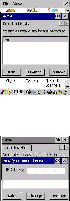
Chapter 5: Configuration
Permitted Hosts
Psion Teklogix 7545 Hand-Held Computer User Manual 153
5.11.4 Permitted Hosts
For security reasons, the Network Administrator may want to restrict SNMP-node access to
a known sub-set of SNMP Managers. This tab lists the IP addresses of all the SNMP Man-
agers which are allowed to monitor and manage this device. If no entries are listed, the
device will accept SNMP queries from any host.
5.11.4.1 Adding A Host
To add a new host:
• Highlight the Add button, and press [ENTER].
• Type a new host IP address in the text box provided, and press [ENTER].
5.11.4.2 Changing A Host
To change an existing host IP address:
• Highlight the IP address you want to alter in the Permitted Hosts tab, and then choose
the Change button.
Preliminary Draft 3
Chapter 5: Configuration
The Storage Manager
154 Psion Teklogix 7545 Hand-Held Computer User Manual
A dialog box like the one displayed when you add a host is displayed.
• Make the necessary changes, and press [ENTER].
5.12 The Storage Manager
The Storage Manager allows you to view information about the storage devices that are
present in the 7545, such as SD-MMC flash cards and Compact Flash cards.
5.12.1 Formatting A Memory Card
Formatting a memory card bulk-erases it. Once a card is erased, partitions may be created in
it, similarly to those on a hard drive. Memory-card devices are normally ‘mounted’ (made
available to the system) automatically when they are inserted. They must be dismounted
before they can be formatted.
To format an entire memory card:
1. Select Start> Settings>Control Panel.
2. In Control Panel, double-click on the Storage Manager icon. The Storage Manager
menu opens:
3. Select the memory card from the drop-down list.
Preliminary Draft 3
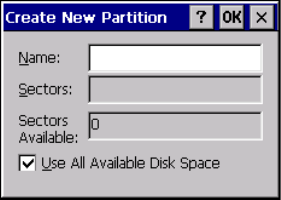
Chapter 5: Configuration
Creating Partitions
Psion Teklogix 7545 Hand-Held Computer User Manual 155
4. Press the Dismount button to dismount the memory card. All partitions on the card
will be dismounted.
5. Press the Format button to format the memory card.
All partitions and information on the card will be erased during the formatting process.
5.12.2 Creating Partitions
Once the card is formatted, new partitions can be created in it. The default is to create one
partition that occupies the whole card, but a card can be divided into more than one partition
if desired. Each partition appears as a separate folder in Windows Explorer.
To create new partitions:
1. Press the New button next to the Partitions list box. The Create New Partition dialog
box appears:
2. Type a name for the partition.
3. If more than one partition is desired, uncheck the Use All Available Diskspace
checkbox, then specify the desired number of sectors to be used by the partition.
Preliminary Draft 3
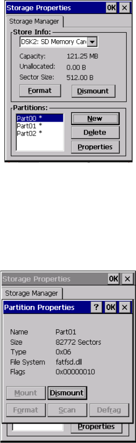
Chapter 5: Configuration
Partition Management
156 Psion Teklogix 7545 Hand-Held Computer User Manual
4. Press OK. The new partition appears in the Partitions list:
The new partition is automatically mounted. This is indicated by an asterisk (*) next to its
name in the partition list. Any unallocated space on the card is indicated at the left, and addi-
tional partitions can be created in it.
5.12.3 Partition Management
Partitions can be individually dismounted, mounted, deleted, or formatted as well. These
and additional tasks are available from the Partition Properties dialog:
To dismount a partition:
1. Choose the desired partition.
Preliminary Draft 3
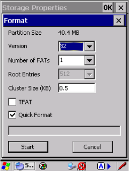
Chapter 5: Configuration
Partition Management
Psion Teklogix 7545 Hand-Held Computer User Manual 157
2. Tap the Properties button. The Partition Properties dialog appears.
3. Tap the Dismount button. The partition is dismounted. The asterisk disappears next
to its name in the partitions list.
To delete a partition:
1. Select the desired partition.
2. Tap the Delete button. A warning dialog appears.
3. Tap the OK button. The partition is deleted.
To format a partition:
1. Choose the desired partition.
2. Tap the Properties button. The Partition Properties dialog appears.
3. Tap the Dismount button. The partition is dismounted. The asterisk disappears next
to its name in the partitions list.
4. Tap the Format button. The Format dialog appears:
5. Choose your format options. These options include:
• Version of file system (FAT-16, for devices holding up to 4 GB; or FAT-32, for
devices containing up to 32 GB).
• Number of FATs (File-Allocation Tables).
• Number of entries allowed in the root directory.
• Cluster size (.5 KB to 64 KB).
There are also two checkboxes, which govern:
Preliminary Draft 3

Chapter 5: Configuration
Teklogix Error Handling Service
158 Psion Teklogix 7545 Hand-Held Computer User Manual
• Whether to use the transaction-safe FAT file system (TFAT). This file system keeps
multiple copies of the file-allocation table, changing one while maintaining another
as a backup.
• Whether to perform a quick format. Quick formatting removes all reference to data in
the partition without erasing the actual partition. The partition will be treated as
empty, and new data will overwrite it.
6. Tap Start. The partition is formatted.
To mount a partition:
1. Choose the desired partition.
2. Tap the Properties button. The Partition Properties dialog appears.
3. Tap the Mount button. The partition is mounted. The asterisk appears next to its
name in the partitions list.
The Partition Properties dialog has buttons for additional functions. Partitions can be defrag-
mented, and their file structure can be scanned.
5.13 Teklogix Error Handling Service
Teklogix Error Handling Service is an error diagnostic tool that allows Psion Teklogix to
deliver more reliable software. When an error occurs, information about that error is saved
in a file which can be sent to Psion Teklogix support personnel to help diagnose the
problem.
• Tap on Start>Settings>Control Panel. Tap on the Teklogix Error Handling
Service icon.
On the Status tab, tapping in the checkbox Enable error reporting enables this service.
5.13.1 ErrorLogInfo
• To log an error, tap on the ErrorLogInfo tab.
Preliminary Draft 3
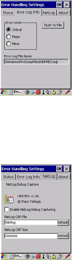
Chapter 5: Configuration
NetLog
Psion Teklogix 7545 Hand-Held Computer User Manual 159
• Choose an Error Level, and tap on FlushToFile to log the information file.
5.13.2 NetLog
The NetLog option is used to log network traffic. When you tap in the checkbox to the left
of Enable NetLog Debug Capturing, debug data is collected so that, if necessary, it can be
forwarded to a Psion Teklogix technician for evaluation. You can also define where you
want the data stored and the maximum size of the file.
Preliminary Draft 3
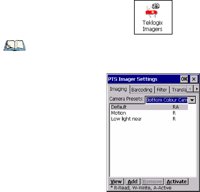
Chapter 5: Configuration
Teklogix Im a g er s
160 Psion Teklogix 7545 Hand-Held Computer User Manual
5.14 Teklogix Imagers
The Teklogix Imagers applet is used to create, modify, delete, and activate imager settings.
The principle uses of the applet are to decode bar codes and to capture images. A PTSI
Imager demo applet is also provided to illustrate how the imager works.
Refer to Appendix D: “Teklogix Imagers Applet” for configuration details.
To launch this applet:
•In the Control Panel, choose the Teklogix Imagers icon.
Note: This icon is only displayed when the appropriate imager is installed in your 7545.
Preliminary Draft 3
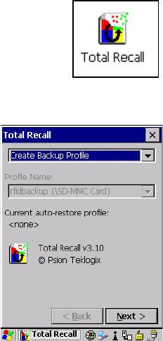
Chapter 5: Configuration
Total Recall
Psion Teklogix 7545 Hand-Held Computer User Manual 161
5.15 Total Recall
Total Recall is a Psion Teklogix utility developed to maintain applications and settings
during a cold boot. This utility is based on a backup and restore concept. This utility is based
on a backup and restore concept
•In the Control Panel, choose the Total Recall icon.
5.15.1 Creating A Backup Profile
In the drop-down menu, you can choose from four options: Create Backup Profile, View Se-
lected Profile Data, Restore Selected Profile and Delete Selected Profile. Keep in mind
however that until a profile is created, the only available option is Create Backup Profile.
• Choose the Next button to begin the process.
Preliminary Draft 3
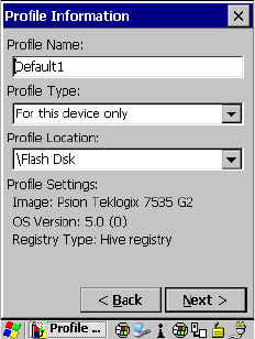
Chapter 5: Configuration
Creating A Backup Profile
162 Psion Teklogix 7545 Hand-Held Computer User Manual
Profile Information
This dialog box lists the possible storage destinations for the profile file.
1. To begin, type a name for the profile in the field labelled Profile Name.
2. Choose the Profile Type you want to create:
For this device only—creates a backup that is manually restored by the operator.
AutoRestore for this device only—creates a profile that automatically restores itself fol-
lowing a restart.
AutoRestore for this and other devices—creates a profile that automatically restores
after resuming from a restart, but it will not contain the touchscreen calibration coordi-
nates or the Wireless radio settings.
3. Finally, choose the Profile Location: \Flash Disk.
4. Tap on the Next button to display the next dialog box Add Files.
Preliminary Draft 3
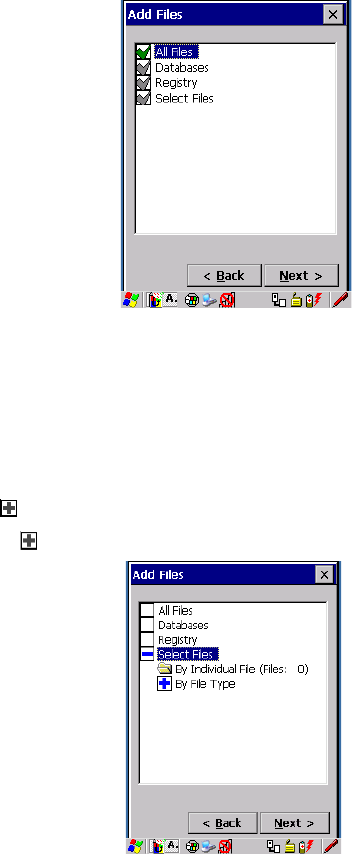
Chapter 5: Configuration
Creating A Backup Profile
Psion Teklogix 7545 Hand-Held Computer User Manual 163
Add Files
By default, All Files is selected so that all installed or copied files, database entries, and the
Registry will be saved. You can, however, limit the backup to databases, and/or the registry
only. By tapping the checkbox next to these items, you can add or remove a check mark to
enable or disable the option.
The Select Files option allows you to select predefined file types.
• Remove the check mark next to All Files. You’ll notice the checkbox next to Select
Files changes , indicating that additional options are available.
• Choose this icon next to Select Files to view your options.
Choosing By Individual File displays a pop-up menu where you can tailor the list of files
you want to back up.
Preliminary Draft 3
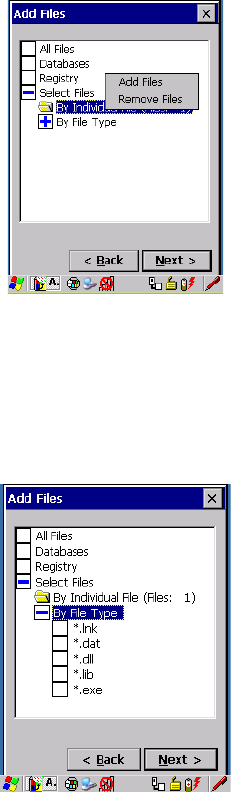
Chapter 5: Configuration
Creating A Backup Profile
164 Psion Teklogix 7545 Hand-Held Computer User Manual
To add a file to your backup list:
• Choose Add Files. Browse to and choose the files you want to add to your list.
To remove a file from your backup list:
• Choose Remove Files—a dialog box is displayed listing the files that will be backed up.
• Highlight the item you want to remove from the list, and tap on the Remove button.
Choosing By File Type allows you to select the file types that you want backed up.
Preliminary Draft 3
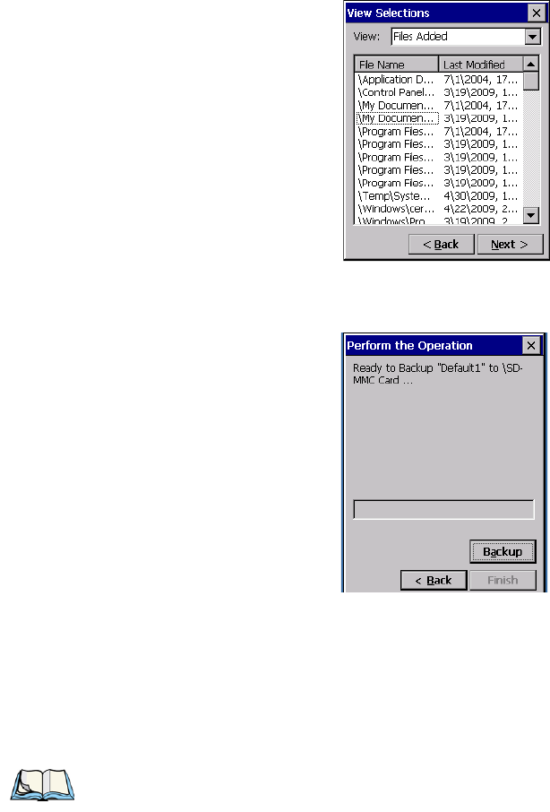
Chapter 5: Configuration
Restoring A Profile
Psion Teklogix 7545 Hand-Held Computer User Manual 165
View Selections
Depending on what you have selected for inclusion in your profile, you can view a list of the
selected files, databases and/or registry.
• Choose the Next button to perform the operation.
Perform The Operation
• Choose the Backup button to start the process, and create a profile.
5.15.2 Restoring A Profile
To manually restore a profile:
• Choose Restore Selected Profile from the drop-down menu, and choose the Profile
Name displayed in the drop down box.
Note: You can also manually restore an auto restore profile located in flash or a
storage device.
Preliminary Draft 3
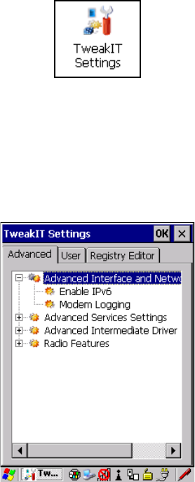
Chapter 5: Configuration
TweakIT Settings
166 Psion Teklogix 7545 Hand-Held Computer User Manual
5.16 TweakIT Settings
This utility allows you to ‘tweak’ or adjust Advanced system settings (interface, network,
servers, driver, and radio), User settings (Internet Explorer settings, font size, and docking
port message), and provides a Registry Editor.
5.16.1 Advanced
5.16.1.1 Advanced Interface And Network
Enable IPv6
This option allows you to enabled Internet Protocol specification, version 6, that has been
published to use 128-bit IP address (replacing version 4).
Modem Logging
When this option is enabled, the 7545 logs AT commands (e.g., dial-out information, pass-
word string, etc.) that the administrator can monitor for debugging purposes. Modem
commands are stored in: \MdmLog.txt.
Preliminary Draft 3
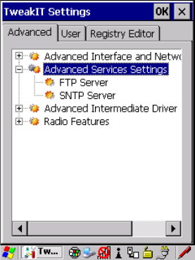
Chapter 5: Configuration
Advanced
Psion Teklogix 7545 Hand-Held Computer User Manual 167
5.16.1.2 Advanced Services Settings
FTP Server
This option is enabled by default to allow file transfers. Keep in mind that data transfer in
either direction is restricted to the Temp folder—that is, data are always loaded from the
FTP Server to the Temp folder and from the Temp folder to the FTP Server.
If this option is disabled, a warm reset must be performed to accept the change.
SNTP (Simple Network Time Protocol) Server
The SNTP Server Name typed in this dialog box is used to synchronize 7545 time with the
time server time. A warm reset must be performed once the server name as been entered.
Preliminary Draft 3
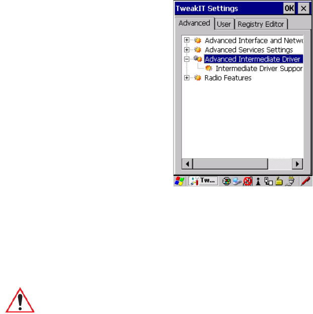
Chapter 5: Configuration
Advanced
168 Psion Teklogix 7545 Hand-Held Computer User Manual
5.16.1.3 Advanced Intermediate Driver
Intermediate Driver Support
The 7545 employs a custom intermediate driver that is used to indicate radio transmission
and reception on its LEDs. As well, the intermediate driver is employed to support the Psion
Teklogix 802.IQ v1 protocol. This TweakIt option is included to allow the driver to be dis-
abled in cases where it interferes with third party drivers or security supplicants. By
disabling the intermediate driver the Rx/Tx LEDs will no longer illuminate.
Important: If 802.IQ v1 is required, this driver must not be disabled.
Preliminary Draft 3
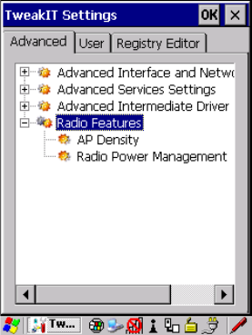
Chapter 5: Configuration
Advanced
Psion Teklogix 7545 Hand-Held Computer User Manual 169
5.16.1.4 Radio Features
AP Density
This option allows you to determine the signal strength at which the 7545 radio will begin
searching for a new Access Point (AP): High, Medium or Low. If, for example, this option is
set to High, the radio will begin searching for a new Access Point while still at a fairly strong
signal strength. Setting AP Density to Low will cause the radio to wait until the signal
strength is significantly low before attempting to connect to another Access Point.
Depending on your site configuration—for example, the shelving, the Access Point cover-
age, etc.—a higher setting may improve through-put, increase and maintain signal strength,
and reduce missed transmissions.
Radio Power Management
When this option is enabled, access points that support it will use Radio Power Management
guidelines to control the client (7545) radio. Access points determine how often the 7545
radio enters sleep mode when no activity is detected to reduce power consumption on the
client side. Another benefit is that when Radio Power Management is enabled, even when
no activity is detected, the access point does not disassociate the 7545 (client).
Preliminary Draft 3
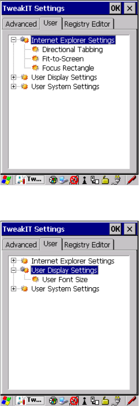
Chapter 5: Configuration
User
170 Psion Teklogix 7545 Hand-Held Computer User Manual
5.16.2 User
5.16.2.1 Internet Explorer Settings
This option allows you to customize how your Internet Explorer is displayed and how the
tabbing functions.
5.16.2.2 User Display Settings
Preliminary Draft 3
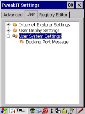
Chapter 5: Configuration
User
Psion Teklogix 7545 Hand-Held Computer User Manual 171
User Font Size
This option allows you to adjust the size of the font used the 7545 display: Large, Normal
or Small.
5.16.2.3 User System Settings
Docking Port Message
Checking this box blocks the message that normally pops up on the display when the 7545
is docked.
Preliminary Draft 3
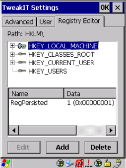
Chapter 5: Configuration
Registry Editor
172 Psion Teklogix 7545 Hand-Held Computer User Manual
5.16.3 Registry Editor
This option is reserved for senior administrators who have a strong understanding of registry
keys and values. Careless registry editing can cause irreversible damage to the 7545.
Preliminary Draft 3

Psion Teklogix 7545 Hand-Held Computer User Manual 195
SPECIFICATIONS 7
7.1 7545 Hand-Held Computer Specifications.......................197
7.1.1 Hardware...................................197
7.1.2 Software ...................................199
7.1.3 Approvals...................................200
7.2 Murata Radio Specifications..............................200
7.3 Internal Scanner Port..................................201
7.6 Internal Scanners and Imagers.............................
7.6.1 SE1224HP - High Performance .......................
Preliminary Draft 3
196 Psion Teklogix 7545 Hand-Held Computer User Manual
7.9 HU3000 - 1900 mAh Lithium-ion Battery Pack ...................220
Preliminary Draft 3

Chapter 7: Specifications
7545 Hand-Held Computer Specifications
Psion Teklogix 7545 Hand-Held Computer User Manual 197
7.1 7545 Hand-Held Computer Specifications
7.1.1 Hardware
Physical Dimensions
• 102mm width x 62.5mm depth x 260mm (4.0 in x 2.5 in x 10.2 in) length.
• Keypad area: 75.5mm width x 36mm (3 in x 1.4 in) depth.
Weight
• With battery 647g (22.83 oz.)
• With pistol grip add 86.4g (3.05 oz.)
User Interface
Color Touchscreen Display: 8.9 cm (3.5 in.) diagonal.
1/4 VGA 240x320 resolution.
Transflective, portrait mode TFT.
Automatic Backlight and Contrast control.
Sunlight readable (for outdoor use).
High-reliability white LED backlight (1.5 ft-L).
256K displayable colours.
Passive stylus or finger operation.
Integral stylus holder.
Keyboards: Numeric.
Alphanumeric.
Numeric with Phone (option only in countries with
GPRS availability).
Ergonomically enhanced for ambidextrous, one-hand
operation.
Backlit, high durability hard-capped keys.
Note: Performance specifications are nominal and subject to change without notice.
Preliminary Draft 3
Chapter 7: Specifications
Hardware
198 Psion Teklogix 7545 Hand-Held Computer User Manual
Indicators And Controls: Multi-colour LEDs indicate battery status, applica-
tion, and radio transmit/receive, user applications.
Internal 95dB beeper with volume control.
Power
• 7.4V @ 1900mAh Li-ion rechargeable battery.
• Intelligent fast charge.
• 8-hour battery operation (5 scans, transmit & receive/min.).
• Built-in gas gauge & performance monitor.
• Quick swap battery packs.
• Built-in fast charger (2 hour typical recharge).
• Self-guiding & latching battery pack design.
• System backup (up to 20 minutes) during battery swap.
• Adjustable battery allocation between system backup and runtime.
• 1 week real-time clock backup.
Communication
Ports:
One docking station port with:
- Power in, 15 VDC nominal, 10 VDC to 19 VDC,
3.5 A maximum
- Power out, 5 VDC +/- 5% @ 1.0 A nominal,
1.5 A peak
Preliminary Draft 3
Chapter 7: Specifications
Software
Psion Teklogix 7545 Hand-Held Computer User Manual 199
Environmental
Guaranteed Operating: -10°C to +50°C (14°F to 122°F)
Temperature Range: Long exposure to temperatures below -40°C
(-40°F) may damage the screen and main battery.
Prolonged exposure to temperatures above +60°C
(+140°F) will damage the main battery and tempera-
tures above +70°C (+158°F) may damage the unit.
Storage Temperature: -25°C to +60°C (-13°F to 140°F)
Rain And Dust Resistance: IEC 529, classification IP65.
Humidity: 5% - 95% RH non-condensing
Drop Durability: Multiple 1.8m (6 ft.) drops or 26 drops from 1.5m
(5 ft.) to concrete while powered on and configured
with accessories such as WiFi radio, scanner/imager,
and pistol grip.
Cradle shock: IEC 60068-2-27: Test Ea, 300 m/s2,
11ms, half-sine, 3 shocks in each of 6 directions.
Cradle vibration: IEC 60068-2-64: Test Fh, Random,
3 axis, 100 min/axis; 5.0 m2/s3 ASD,
10 - 200 Hz; 1.0 m2/s3 ASD, 200 - 500 Hz.
7.1.2 Software
Processor And Memory
• XScale PXA270 @ 520 MHz Processor.
• RAM: 128MB SDRAM standard.
• Flash ROM: 64MB FLASH standard.
Operating System
• Microsoft Windows Embedded CE 5.0
Preliminary Draft 3
Chapter 7: Specifications
Approvals
200 Psion Teklogix 7545 Hand-Held Computer User Manual
7.1.3 Approvals
Safety: IEC 60950-1
EMC: FCC Part 15 Class B
EN 55022
EN 55024
EN 301 489
Laser: IEC 60825-1 Ed. 2.0, Class 1, Class 2
FDA 21 CFR 1040.10
1040.11 Class I, Class II
Bluetooth:2.0
RF: Bluetooth and 802.11b/g: EN300 328, Part 15.247
RoHS compliant: EU Directive 2002/95/EC
7.2 Murata Radio Specifications
802.11b/g Radio: Direct Sequence Spread Spectrum (DSSS)
Form factor Embedded surface mount module, 8.2 x 8.4 mm
Antenna port U.FL jack
Transmit Power 802.11b/g: 50mW typical (+17 dBm)
Frequency Range 2.400 - 2.4835 GHz
Channels This radio supports 802.11d. The radio will associ-
ate with any 802.11d compliant AP, regardless of
what channel is in use.
RX Sensitivity -86dBm typ @ 11Mbps
-82dBm @ 6Mbps, -69dBm @ 54Mbps
Data Rates 802.11g: 6, 9, 12, 18, 24, 36, 48, 54Mbps
802.11b: 1, 2, 5.5, 11 Mbps
EVM 802.11b: -28 dB typ (16%)
802.11g: -29 dB typ (13%)
Bluetooth Co-existent 2-line hardware handshake with Bluetooth radio
Preliminary Draft 3
Chapter 7: Specifications
Internal Scanner Port
Psion Teklogix 7545 Hand-Held Computer User Manual 201
Murata Bluetooth Radio
Form Factor Embedded (920 kbps serial interface)
Bluetooth Version Ver 2 compliant - features Adaptive Frequency
Hopping (AFH) for better co-existence with 802.11
radio and Enhanced Data Rate (EDR) for up to
3Mbps data rate.
Antenna Type Ceramic chip PIFA
Antenna Gain 1 dBi peak
Transmit Power -3 dBm (0.5mW) minimum, +4 dBm (2.5mW) max
Frequency Range 2.400–2.4835 GHz
RX Sensitivity (BER<0.1%) -80 dBm max
Data Rate V1.2 = 732.2 kbps and 57.6 kbps asymmetric,
433.9 kbps symmetric
V2.0 = 2 & 3 Mbps
802.11 Co-existent 2-line hardware handshake with 802.11 radio
7.3 Internal Scanner Port
Compatibility
1D Laser Scanners:
SE1224HP decoded, fuzzy logic, enhanced standard
range
Preliminary Draft 3

Chapter 7: Specifications
SE1223LR - Long Range (decoded)
Psion Teklogix 7545 Hand-Held Computer User Manual 209
7.6.8 SE1223LR - Long Range (decoded)
7.6.9 SE1224HP - High Performance
Parameter SE1223LR
Light Source Visible Laser Diode 650 nm
Scan Rate 35 (± 5) scans/sec (bi-directional)
Scan Angle 23º ± 2º
Scan Patterns Linear
Minimum Print Contrast Minimum 40% absolute dark/light reflectance measured at
650 nm.
Symbologies Supported UPC/EAN, Code 128, Code 39, Code 93, I 2 of 5, Discrete 2 of 5,
Codabar, MSI, UCC/EAN 128, TriOptic Code 39.
Programmable Parameters Laser On Time, Aim Duration, Power Mode, Trigger Mode, Bi-
directional Redundancy, Symbology types/lengths, Data format-
ting, Serial Parameters, Beeper Tone.
Ambient Light: Artificial: 450 ft. candles (4,844 Lux).
Sunlight: 8,000 ft. candles (86,112 Lux).
Power Input Voltage: 5.0 VDC ± 10%
Input Current: 115 mA typical
Standby Current: 70 µA max.
Laser Classification Intended for use in CDRH Class II and IEC Class 2 devices
Electrical Safety UL, VDE, and CUL recognized component laser
Environmental RoHS-compliant
Parameter SE1224HP
Type Laser Class 2
Light Source Visible Laser Diode 650 nm
Scan Rate 35 (± 5) scans/sec (bi-directional)
Scan Angle/Field of View 42º (typical), 30º (narrow)
Scan Patterns Linear
Preliminary Draft 3
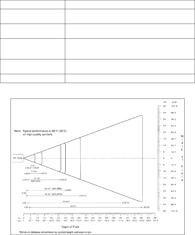
Chapter 7: Specifications
SE1224HP - High Performance
210 Psion Teklogix 7545 Hand-Held Computer User Manual
7.6.9.1 SE1224HP Decode Zones
Minimum Print Contrast Minimum 25% absolute dark/light reflectance measured at
650 nm.
Symbologies UPC/EAN, Code 128, UCC/EAN 128, RSS, Code 39, Code 93, I
2 of 5, Discrete 2 of 5, Codabar, MSI.
Programmable Parameters Laser On Time, Aim Duration, Power Mode, Trigger Mode, Bi-
directional Redundancy, Symbology types/lengths, Data format-
ting.
Ambient Light Artificial: 450 ft. candles (4844 Lux).
Sunlight: 8000 ft. candles (86112 Lux).
Laser Output Power (peak) 1.35mW
Parameter SE1224HP
Preliminary Draft 3
Preliminary Draft 3

Psion Teklogix 7545 Hand-Held Computer User Manual B-1
APPENDIX B
SCU FOR 802.11B/G RADIO
B.1 SCU Tabs.........................................3
B.1.1 Main ......................................3
B.1.2 Profile......................................4
B.1.3 Status......................................9
B.1.4 Diags......................................9
B.1.2.1 SCU Security Capabilities.......................6
B.1.2.2 SCU EAP Types............................7
B.1.2.3 EAP Credentials............................7
B.1.2.4 ThirdPartyConfig...........................8
B.1.5 Global..................................... 10
Preliminary Draft 3
Preliminary Draft 3
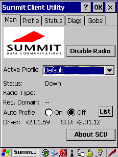
Appendix B: SCU For 802.11b/g Radio
SCU Tabs
Psion Teklogix 7545 Hand-Held Computer User Manual B-3
B.1 SCU Tabs
This appendix provides details about each tab in the Summit Client Utility (SCU). For
quick, step-by-step setup instructions, refer to “Summit Client Utility (SCU) For 802.11b/g
Radio” on page 28.
The following sections provide a detailed description of each of the tabs available in the
SCU—Main (below), Profile (page B-4), Status (page B-9), Diags (page B-9), and Global
(page B-10).
B.1.1 Main
The Main tab is displayed when you tap on the Start>Programs>SCU icon.
•Enable/Disable Radio: Enables or disables the radio. This is a toggle button; when the
radio is enabled, this button reads Disable Radio, and when the radio is disabled, the
button reads Enable Radio.
•Active Profile: Lists the name(s) of the active configuration profile(s). When a profile
is chosen from the Active Profile drop-down menu, the settings for that profile become
active.
If ThirdPartyConfig is selected, after the 7545 goes through a power cycle, WZC is used
for configuration of the radio. See “ThirdPartyConfig” on page B-8 for details.
•Radio Type: Indicates the type of radio installed in the device, e.g. “ABG” when an
802.11a/b/g radio is installed.
•Reg. Domain: Indicates the regulatory domain (e.g. ETSI, FCC or TELEC) for which
the radio is configured. “Worldwide” means that the radio can be used in any domain.
•Status: Indicates if the radio is associated to an access point. If this is not the case,
Status indicates the radio status.
Preliminary Draft 3
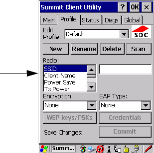
B-4 Psion Teklogix 7545 Hand-Held Computer User Manual
Appendix B: SCU For 802.11b/g Radio
Profile
•Driver and SCU: These fields display the version of the device driver and the SCU that
are running on the 7545.
•About SCU: This box provides details about the SCU software.
B.1.2 Profile
The Profile tab allows you to define radio and security settings that are stored in the registry
as part of the configuration profile.
The profile you create and save is listed in the Active Profile drop-down menu in the Main
tab. You can define up to 20 profiles.
•Edit Profile: Used to choose the profile to be viewed or edited. If ThirdPartyConfig is
chosen, after the 7545 goes through a power cycle, WZC is used for configuration of
the radio.
•New: Allows you to create a new profile with default settings and assign it a name.
•Rename: Allows you to assign a profile name.
•Delete: Deletes the profile unless it is currently active.
•Scan: Opens a new window which displays a list of available access points with their
respective SSIDs, Signal Strength (RSSI value) and Security Status. Selecting an AP
returns you to the profile page and populates a new profile with the information availa-
ble from the scan to simplify setting up a new profile.
•Radio: Lists radio attributes. These attributes can be individually chosen from this
menu. When an attribute is chosen, an associated list of options is displayed where you
can assign new settings or view existing settings.
•Commit: Saves all changes.
Radio
Attributes
Preliminary Draft 3

Appendix B: SCU For 802.11b/g Radio
Profile
Psion Teklogix 7545 Hand-Held Computer User Manual B-5
The following table describes the options in the Radio attributes, Encryption, and EAP Type
drop-down menus:
Table B.1 Radio, Encryption, And EAP Menus
Radio
Attribute Description Value Default
SSID Service set identifier (SSID) for
WLAN to which the radio connects.
Maximum of 32 characters. None
Client
Name
Name assigned to radio & 7545 into
which it is installed.
Maximum of 16 characters. None
Power Save Power save mode for radio. CAM: Constantly awake.
Maximum: Maximum power sav-
ings.
Fast: Fast power save mode.
Fast
Tx Power Maximum transmit power. Max: Maximum defined for
current regulatory domain.
Measured in mW: 50,30,10, 1.
Max
Bit Rate Used by radio when interacting
with WLAN access point.
Auto: Rate automatically negoti-
ated with access point.
Rates in Mbps: 1, 2, 5.5, 6.9 11,
12, 18, 24, 36, 48, 54.
Auto
Radio
Mode
Used by 802.11g when interacting
with access point.
B rates only: 1, 2, 5.5, & 11 Mbps.
G rates only: 6, 9, 12, 18, 24, 36,
48, and 54 Mbps.
BG rates full: All B and G rates.
BG rates optimized: 1, 2, 5.5, 6,
11, 24, 36 & 54 Mbps.
BG rates
optimized
Auth Type 802.11 authentication type used
when associating with access point.
Open, shared-key, or LEAP (Net-
work-EAP).
Open
EAP Type Extensible Authentication Protocol
type used for 802.1X authentica-
tion to access point.
None, LEAP, EAP-FAST, PEAP-
MSCHAP
– To use EAP-TLS, you must
use WZC.
None
Preliminary Draft 3

B-6 Psion Teklogix 7545 Hand-Held Computer User Manual
Appendix B: SCU For 802.11b/g Radio
Profile
•EAP-Type & Encryption: Security settings. These settings allow you to enhance the
security of data across the wireless LAN. Refer to “EAP Credentials” on page B-7 and
‘SCU Security Capabilities’ below, for details about these settings.
B.1.2.1 SCU Security Capabilities
The SCU provides integrated security to protect transmitted data as well as the 7545 and
wireless WAN infrastructure that transmit and receive data.
A foundational element of the IEEE 802.11i WLAN security standard is IEEE 802.1X and a
critical application on a mobile device is an 802.1X supplicant. This supplicant provides an
interface between the radio and the operating system and supports the authentication and en-
cryption elements required for 802.11i, also known as Wi-Fi Protected Access 2 (WPA2), as
well as predecessors such as WPA and WEP. Summit software includes an integrated suppli-
cant that supports a broad range of security capabilities, including:
• 802.1X authentication using pre-shared keys or an EAP type, required for WPA2 and
WPA.
• Data encryption and decryption using WPA2 AES, WPA TKIP or WEP.
Common EAP types include:
•EAP-TLS: Uses the same technology as a follow-on to Secure Socket Layer (SSL). It
provides strong security, but relies on client certificates for user authentication.
Credentials Authentication credentials for the
selected EAP type.
Refer to “EAP Credentials” on
page B-7.
User: Username or Domain/User-
name (up to 64 characters).
Password: up to 64 characters.
For PEAP: CA Cert–CA server
certificate filename.
None
Encryption Type of encryption used to protect
transmitted data.
None, Manual WEP, Auto WEP
(generated during EAP authenti-
cation), WPA PSK, WPA TKIP,
WPA2 PSK, WPA2 TKIP, WPA2
AES, CCKM TKIP.
For Manual WEP: Up to four
static WEP keys.
For PSK: ASCII passphrase or
hex PSK.
None
Table B.1 Radio, Encryption, And EAP Menus
Radio
Attribute Description Value Default
Preliminary Draft 3

Appendix B: SCU For 802.11b/g Radio
Profile
Psion Teklogix 7545 Hand-Held Computer User Manual B-7
•PEAP: Provides secure user authentication by using a TLS tunnel to encrypt EAP traf-
fic. Two different inner methods are used with PEAP:
- EAP-MSCHAPV2, resulting in PEAP-MSCHAP: This is appropriate for use against
Windows Active Directory and domains.
- EAP-GTC, resulting in PEAP-GTC: This is for authentication with one-time pass-
words (OTPs) against OTP databases such as SecureID.
•LEAP: Is an authentication method for use with Cisco WLAN access points. LEAP
does not require the use of server or client certificates. LEAP supports Windows Active
Directory and domains but requires the use of strong passwords to avoid vulnerability to
offline dictionary attacks.
•EAP-FAST: Is a successor to LEAP and does not require strong passwords to protect
against offline dictionary attacks. Like LEAP, EAP-FAST does not require the use of
server or client certificates and supports Windows Active Directory and domains.
B.1.2.2 SCU EAP Types
The following EAP types are supported by the integrated supplicant and can be configured
in SCU: PEAP-MSCHAP, PEAP-GTC, LEAP and EAP-FAST. With each of these four
types, if authentication credentials are not stored in the profile, you will be prompted to enter
credentials the first time the radio attempts to associate to an access point that supports
802.1X (EAP).
Consider the following when configuring one of the EAP types:
•PEAP-GTC: SCU supports static (login) passwords only.
•LEAP: Strong passwords are recommended.
•EAP-FAST: SCU supports automatic, not manual, PAC provisioning.
EAP-TLS will work with an 802.11a/b/g radio module when Windows Zero Config (WZC)
rather than the SCU is used to configure the type. With WZC, the native Windows supplicant
instead of the SCU integrated supplicant is used.
B.1.2.3 EAP Credentials
Keep the following in mind when defining security settings:
• If the credentials specified in the profile are incorrect and that profile is used, the
authentication fails without an error message; you will not be prompted to enter
correct credentials.
Note: PEAP and EAP-TLS require the use of Windows facilities for the configuration of
digital certificates.
Preliminary Draft 3
B-8 Psion Teklogix 7545 Hand-Held Computer User Manual
Appendix B: SCU For 802.11b/g Radio
Profile
• If the credentials are not specified in the profile, when the radio tries to associate using
that profile, you will be prompted to enter the credentials.
• When prompted, you can enter valid credentials, enter invalid credentials, or cancel
the operation.
- If you enter valid credentials and tap OK, the radio will associate and authenticate.
- If you enter invalid credentials and tap on OK, the radio will associate but will not
authenticate; you will be prompted again to enter credentials.
- If you tap on Cancel or clear the credentials fields and tap on OK, the radio will not
attempt to associate with that profile until you perform one of the following actions
(while the profile is the active profile):
- Cause the 7545 to go through a power cycle or suspend/resume.
- Disable and enable the radio, or tap the Reconnect button on the Diags windows.
- Modify the Profile, and tap on Commit.
Alternatively, you can choose another profile as the active profile and then switch back to
the profile for which EAP authentication was cancelled.
B.1.2.4 ThirdPartyConfig
If you choose to configure ThirdPartyConfig, the SCU will work with the operating sys-
tem’s Windows Zero Config (WZC) to configure radio and security settings for the CF radio
installed in the unit.
Choosing this profile means that WZC must be used to define the following radio and secu-
rity options: SSID, Auth Type, EAP Type, and Encryption.The SCU settings for
ThirdPartyConfig include: Client Name, Power Save, Tx Power, Bit Rate, and Radio Mode.
These SCU settings along with SCU global settings and the WZC settings will be applied to
the radio module.
Preliminary Draft 3
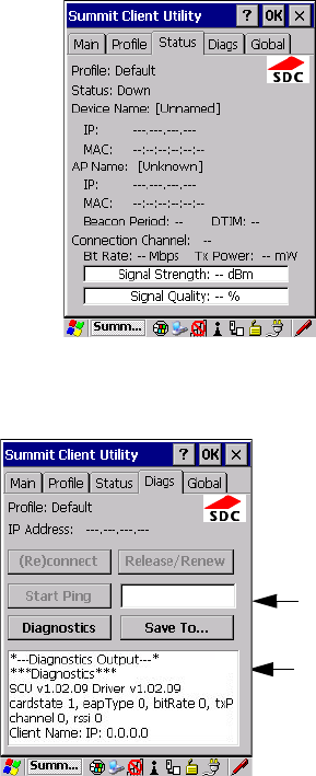
Appendix B: SCU For 802.11b/g Radio
Status
Psion Teklogix 7545 Hand-Held Computer User Manual B-9
B.1.3 Status
The Status tab provides status information including IP address and MAC address for the
client radio, IP address and MAC address for the AP, signal strength, channel, transmit
power and data rate.
B.1.4 Diags
Use the Diags tab as a troubleshooting tool. The functions are as follows:
•(Re)Connect: Enables/Disables the radio, applies/reapplies current profile and tries to
associate and authenticate to the wireless LAN, logging all activity in the output area at
bottom of the dialog box.
Ping Address
Ping Results
Preliminary Draft 3
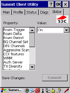
B-10 Psion Teklogix 7545 Hand-Held Computer User Manual
Appendix B: SCU For 802.11b/g Radio
Global
•Release/Renew: Obtains a new IP address through DHCP and logs all activity in the
output area.
•Start Ping: Starts a continuous ping to the address in the text box next to this button.
This is a toggle button so when you tap on it, it changes to Stop Ping. Closing this
window or tapping on another button also stops the ping.
•Diagnostics: Attempts to connect or reconnect to an AP, and provides a more detailed
dump of data than if you used (Re)connect. The dump includes the radio state, profile
settings, global settings and BSSID list of APs. The SCU is saved to a file called
_sdc_diag.txt in the Windows directory.
B.1.5 Global
The Global settings tab allows you to define radio and security settings that apply to all pro-
files, along with settings that apply specifically to the SCU. The Global settings in Table B.2
can be edited in SCU.
Preliminary Draft 3

Appendix B: SCU For 802.11b/g Radio
Global
Psion Teklogix 7545 Hand-Held Computer User Manual B-11
Ta b l e B . 2 G l o b a l Ta b
Global Setting Description Value Default
Roam Trigger If RSSI from AP is less than roam
trigger value, radio performs roam scan
or probes for an AP with stronger
signal.
dBm: -50, -55, -60, -65,
-70, -75, Custom
-75
Roam Delta Amount by which second AP’s RSSI
must exceed the moving average RSSI
for the current AP before the radio will
attempt to roam to a second AP.
dBm: 5, 10, 15, 20, 25,
30, 35, Custom
10
Roam Period Following an association or roam scan
(with no roam), the number of seconds
the radio collects RSSI scan data before
considering roaming.
Seconds: 5, 10, 15, 20,
25, 30, 35, 40, 45, 50,
55, 60, Custom
10
BG Channel Set Defines the 2.4 GHz channels to be
scanned when the radio is set to roam
and needs to determine what APs are
available.
Full (all channels)
1, 6, 11
1, 7, 13
Custom
Full
DFS Channels Reserved Off, On Off
Aggressive Scan When this setting is On and the current
connection to an AP becomes unrelia-
ble, the radio scans for available APs
more aggressively. Aggressive scan-
ning complements and works in con-
junction with the standard scanning
that is configured through the Roam
Trigger, Roam Delta, and Roam Period
settings. It is recommended that
Aggressive Scan is left On unless there
is significant co-channel interference
because of overlapping coverage from
APs on the same channel.
Off, On On
CCX features Activates three CCX features: AP-
assisted roaming, AP-specified
maximum transmit power and
radio management.
Optimized, Full, Off Optimized
Preliminary Draft 3

B-12 Psion Teklogix 7545 Hand-Held Computer User Manual
Appendix B: SCU For 802.11b/g Radio
Global
WMM Use Wi-Fi Multimedia Extensions, also
know as WMM.
On, Off Off
TX Diversity Defines how to handle antenna diver-
sity when transmitting data to AP.
-Main only: Use main
antenna only.
-Aux only: Use auxil-
iary antenna only.
-On: Use diversity.
Main only
RX Diversity Defines how to handle antenna diver-
sity when receiving data from AP.
-On-Start on Main: On
startup, use main
antenna.
-On-Start on Aux: On
startup, use auxiliary
antenna.
-Main only: Use main
antenna only.
-Aux only: Use auxil-
iary antenna only.
On-Start on
Main
Frag Thresh Packet is fragmented when packet size
(in bytes) exceeds threshold.
Integer from 256 to
2346.
2346
RTS Thresh Packet size above which RTS/CTS is
required on link.
An integer from 0 to
2347.
2347
LED Available only with MCF10G. On, Off Off
Tray Icon Enables the System Tray icon. Off, On Off
Hide Passwords On - SCU as well as EAP authentica-
tion dialog boxes hide passwords, WEP
keys and other sensitive information.
On, Off Off
Admin Password Password that must be specified when
Admin Login button is pressed.
A string of up to 64
characters.
SUMMIT
Ta b l e B . 2 G l o b a l Ta b
Global Setting Description Value Default
Preliminary Draft 3

Appendix B: SCU For 802.11b/g Radio
Global
Psion Teklogix 7545 Hand-Held Computer User Manual B-13
Auth Timeout Specifies the number of seconds that
the software will wait for an EAP
authentication request to succeed or
fail. If authentication credentials are
specified in the active profile and the
authentication times out, then associa-
tion will fail. If authentication creden-
tials are not specified in the active
profile and the authentication times out,
then you will be re-prompted to enter
authentication credentials.
An integer from 3 to 60. 8
Certs Path Directory where certificates for EAP
authentication are stored.
Valid directory path up
to 64 characters.
Dependent
on device.
Ping Payload Amount of data to be transmitted on a
ping.
Bytes: 32, 64, 128, 256,
512, 1024
32
Ping Timeout ms Amount of time in milliseconds that
passes without a response before ping
request is considered a failure.
Integer from 0 to
30000.
5000
Ping Delay ms Amount of time in milliseconds
between successive ping requests.
Integer from 0 to
7200000.
1000
Ta b l e B . 2 G l o b a l Ta b
Global Setting Description Value Default
Preliminary Draft 3
Preliminary Draft 3

Psion Teklogix 7545 Hand-Held Computer User Manual C-1
APPENDIX C
BAR CODE SETTINGS
C.1 Bar Code Settings.....................................5
C.1.1 Scanner Options ................................5
C.1.2 Restoring Default Settings...........................6
C.2 Decoded (Internal) Scanners...............................7
C.2.1 Options.....................................7
C.2.2 Decoded (Internal) Advanced Options.....................8
C.2.3 Decoded (Internal) 2D Scanning Options.................. 10
C.2.4 Decoded (Internal) Data Options........................11
C.2.5 Code 39.................................... 12
C.2.6 Code 128................................... 15
C.2.7 EAN 13.................................... 16
C.2.8 EAN 8..................................... 16
C.2.9 UPC A .................................... 16
C.2.10 UPC E.................................... 17
C.2.11 UPC/EAN Shared Settings......................... 18
C.2.12 Code 93................................... 19
C.2.13 Codabar................................... 19
C.2.14 MSI Plessey................................. 20
C.2.15 Interleaved 2 of 5.............................. 21
C.2.16 Discrete 2 of 5................................ 22
C.2.17 RSS Code (Reduced Space Symbology) .................. 22
C.2.18 Composite.................................. 23
C.2.19 PDF-417................................... 24
C.2.20 Micro PDF-417............................... 24
C.3 Decoded (Intermec ISCP) ............................... 25
C.3.1 Decoded (ISCP) Options........................... 25
C.3.2 Decoded (ISCP) Advanced Options..................... 25
C.3.3 Code 39.................................... 26
C.3.4 Code 128................................... 28
Preliminary Draft 3
C-2 Psion Teklogix 7545 Hand-Held Computer User Manual
Appendix C: Bar Code Settings
C.3.5 EAN 13....................................29
C.3.6 EAN 8.....................................30
C.3.7 UPC A.....................................30
C.3.8 UPC E Settings ................................31
C.3.9 UPC/EAN Shared Settings..........................31
C.3.10 Code 93....................................32
C.3.11 Codabar....................................33
C.3.12 MSI Plessey.................................34
C.3.13 Code 11....................................35
C.3.14 Interleaved 2 of 5...............................35
C.3.15 Matrix 2 of 5.................................36
C.3.16 Discrete 2 of 5................................37
C.3.17 Telepen....................................37
C.3.18 RSS Code (Reduced Space Symbology)...................38
C.3.19 Composite..................................39
C.3.20 TLC-39....................................39
C.3.21 PDF-417...................................40
C.3.22 Micro PDF-417................................40
C.3.23 Codablock..................................41
C.4 Imager..........................................41
C.4.1 Imager Options ................................41
C.4.2 Imager Advanced Options...........................43
C.4.3 Code 39....................................45
C.4.4 Code 128....................................46
C.4.5 EAN 13....................................46
C.4.6 EAN 8.....................................47
C.4.7 UPC A.....................................47
C.4.8 UPC E.....................................47
C.4.9 Code 93....................................48
C.4.10 Codabar....................................48
C.4.11 Interleaved 2 of 5...............................48
C.4.12 RSS Code (Reduced Space Symbology)...................49
C.4.13 Composite..................................49
C.4.14 PDF-417...................................49
C.4.15 Micro PDF-417................................50
C.4.16 2D Data Matrix................................50
Preliminary Draft 3
Appendix C: Bar Code Settings
Psion Teklogix 7545 Hand-Held Computer User Manual C-3
C.4.17 2D QR Code.................................50
C.4.18 2D Maxicode ................................51
C.4.19 2D Aztec...................................51
C.4.20 Postal: PlaNET ...............................51
C.4.21 Postal: PostNET...............................52
C.4.22 Postal: Australian..............................52
C.4.23 Postal: Japanese...............................52
C.4.24 Postal: Korean................................53
C.4.25 Postal: Royal.................................53
C.4.26 Postal: Kix..................................53
C.4.27 Postal: Canadian...............................53
C.5 Non-Decoded Scanners.................................54
C.5.1 Options....................................55
C.5.2 Code 39....................................55
C.5.3 Code 128...................................57
C.5.4 EAN 13....................................58
C.5.5 EAN 8.....................................59
C.5.6 UPC A.....................................59
C.5.7 UPC E.....................................60
C.5.8 Codabar....................................61
C.5.9 Code 93....................................61
C.5.10 Code 11...................................62
C.5.11 Interleaved 2 of 5 ..............................63
C.5.12 MSI Plessey.................................63
C.5.13 Discrete 2 of 5................................64
C.5.14 IATA 2 of 5 .................................65
Preliminary Draft 3
Preliminary Draft 3
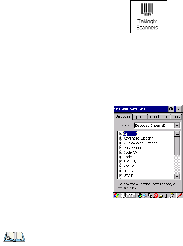
Appendix C: Bar Code Settings
Bar Code Settings
Psion Teklogix 7545 Hand-Held Computer User Manual C-5
C.1 Bar Code Settings
The Teklogix Scanners icon in the Control Panel provides dialog boxes in which you can
tailor bar code options and choose the bar codes your scanner will recognize.
The parameters are preset with the default settings of the decoded scanner installed in the
unit. For a listing of available scanners and their specifications, please refer to Chapter 7:
“Specifications”.
C.1.1 Scanner Options
The drop-down menu to the right of the Scanner option allows you to choose configurations
for one of the following scanner types, depending on what is installed in/on your hand-held:
Decoded (internal), Decoded (Intermec ISCP), Imager, and Non-decoded.
The symbologies listed change to reflect the scanner you choose and the bar codes it sup-
ports. Always defer to your bar code scanner’s programming manual when in doubt about
the availability or settings for any parameter.
Note: Your 7545 comes preconfigured from the factory for internal scanner types. The
type of scanner installed can be determined from the System icon in the Control
Panel, under the System Properties tab.
Preliminary Draft 3
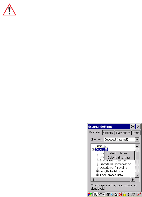
C-6 Psion Teklogix 7545 Hand-Held Computer User Manual
Appendix C: Bar Code Settings
Restoring Default Settings
Keep in mind that some bar code types are only available when an internal imaging scanner
is installed. All internal scanners can be configured using these dialog boxes. External, non-
decoded scanners are also configured through the Scanner Properties dialog box.
However, external decoded scanners must be configured by scanning special configuration
bar codes. In these cases, the scanner manufacturer provides programming manuals for con-
figuration purposes.
• For the Symbol LS3408 decoded scanner, refer to the programming guide supplied with
your scanner.
•For PowerScan
® (PSC) decoded scanners, refer to the PowerScan Programming Guide
C.1.2 Restoring Default Settings
If you want to restore the factory defaults after making changes, the defaults can be applied
to a selected parameter, sub-tree of parameters, or all scanner parameters.
• Press and hold the stylus on a symbology (e.g., Code 128) to display a pop up a menu.
• Choose Default subtree to reset only the parameters in the symbology you selected, or
choose Default all settings to reset all scanner parameters to default settings.
To reset a single parameter to its default setting:
Important: To improve the decode speed and performance, enable (set to ‘on’) only
those codes that are required by the application.
Preliminary Draft 3
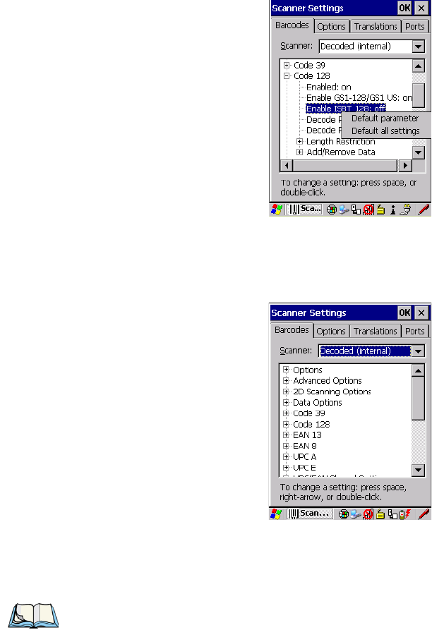
Psion Teklogix 7545 Hand-Held Computer User Manual C-7
Appendix C: Bar Code Settings
Decoded (Internal) Scanners
Options
• Press and hold the stylus on the parameter you want to reset.
• Choose Default parameter to reset the parameter to the default setting.
C.2 Decoded (Internal) Scanners
• Tap on the Scanner drop-down menu, and choose Decoded (internal).
C.2.1 Options
Note: Some options are available only for specific scanners. Refer to the option names in
this section for scanner model identification.
Preliminary Draft 3
C-8 Psion Teklogix 7545 Hand-Held Computer User Manual
Appendix C: Bar Code Settings
Decoded (Internal) Scanners
Decoded (Internal) Advanced Options
Dot Time (msec)
The value selected for Dot Time (msec) determines (in milliseconds) how long the targeting
dot remains on before the scanner switches to a normal scan sweep. When you double-tap
on this parameter, a dialog box is displayed in which you can enter a value of 0 msec, 200
msec or 400 msec. A value of 0 (zero) disables the target dot.
Aim Duration
This parameter determines the total time the aiming pattern appears before the scanner laser
begins sweeping. When you double-tap on this parameter, a dialog box is displayed in which
you can enter a value from 0 to 30 (0 to 3 sec.). A value of 0 (zero) disables the aiming-dot.
Laser On Time
The value assigned to this parameter determines how long the laser will remain on when the
scan button or trigger is pressed.
Double-tapping on this parameter displays a dialog box in which you can enter a value
between 5 and 99, each number representing 0.1 seconds.
C.2.2 Decoded (Internal) Advanced Options
Continuous Scan Mode
Setting this parameter to on keeps the laser on and continuously decoding as long as the
scanner button is pressed and held down.
Minimum Cancel Time
The value assigned to this parameter determines the time delay before the scanner is turned
off, once the scanner trigger or button is released. This gives the scanner a minimum amount
of time to complete its current decode before the scan is cancelled when you quickly trigger
on/off.
Power Mode
This parameter is a power-saving option. Tapping on it displays a screen listing two power
mode options: Continuous Power and Low Power.
In Continuous Power mode, the scanner is always on, waiting for a trigger pull or a serial
communication.
In Low Power mode, the scanner is in a standby state, drawing minimal power until a trigger
pull or serial communication wakes it. Keep in mind that while this option is more suitable
Preliminary Draft 3

Psion Teklogix 7545 Hand-Held Computer User Manual C-9
Appendix C: Bar Code Settings
Decoded (Internal) Scanners
Decoded (Internal) Advanced Options
for battery powered applications, there will be a slight delay while the scanner powers up to
scan a bar code.
Low Power Timeout
To extend laser life, you can select the time the scanner remains active following a success-
ful decode. The scanner wakes from low power mode when a bar code is scanned—a
successful decode restores normal blinking.
This is only used if the unit’s Trigger Mode has been changed to Continuous On. If the
unit is used in a fixed mount this parameter might be used, but not if the unit is used as
a hand-held.
When you double-tap on this parameter, a dialog box is displayed in which you can choose a
value of 30 sec., 1 min., 2 min. or 3 min.
Parameter Scanning
Setting this parameter to on enables decoding of parameter bar codes.
Linear Security Level
This parameter allows you to select the security level appropriate for your bar code quality.
There are four levels of decode security for linear code types (e.g., Code 39,
Interleaved 2 of 5). Higher security levels should be selected for decreasing levels of bar
code quality. As security levels increase, the scanner’s decode speed decreases.
Double-tapping on this parameter displays a dialog box in which you can enter a value from
1 to 4.
Linear security level 1 specifies that the following code types must be successfully read
twice before being decoded:
Linear security level 2 specifies that all types of codes must be successfully read twice
before being decoded.
Note: This parameter is only used if the Trigger Mode has been set to Continuous On and
the 7545 is mounted in a fixed position; otherwise, ‘Low Power Timeout’ is not used.
Code Type Length
Codabar All
MSI Plessey 4 or less
D 5 of 5 8 or less
I 2 of 5 8 or less
Preliminary Draft 3
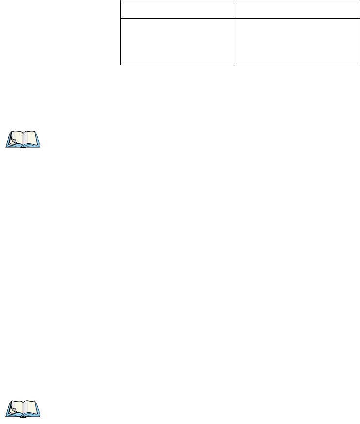
C-10 Psion Teklogix 7545 Hand-Held Computer User Manual
Appendix C: Bar Code Settings
Decoded (Internal) Scanners
Decoded (Internal) 2D Scanning Options
Linear security level 3 specifies that code types other than the following must be success-
fully read twice before being decoded. The following codes must be read three times:
Linear security level 4 requires that all code types be successfully read three times before
being decoded.
Bi-Direction Redundancy
When this parameter is enabled, a bar code must be successfully scanned in both directions
(forward and reverse) before being decoded.
Scan Angle
This option allows you to choose from two scan angles: Normal Angle or Alternate Angle.
Choosing Normal Angle allows the normal operation for scanning long range and short
range. Choosing Alternate Angle widens the beam to allow scanning of long bar codes at
short range but at the cost of long range scanning.
C.2.3 Decoded (Internal) 2D Scanning Options
Scanning Mode
When you double-tap on this parameter, a dialog box is displayed in which you can choose
one of the following scanning modes: Smart Raster, Always Raster, Programmable Raster,
Slab Pattern, Cyclone Pattern, or Semi-Omni Pattern.
Raster Height And Raster Expand Rate
These parameters determine the laser pattern’s height and rate of expansion.
Code Type Length
MSI Plessey 4 or less
D 2 of 5 8 or less
I 2 of 5 8 or less
Note: This parameter is only valid if a” Linear Security Level” is enabled.
Note: These parameters are only used when either Programmable Raster or
Always Raster is assigned to the “2D Scanning Mode” parameter. “2D Raster
Height” and “2D Raster Expand Rate” are intended for very specific applications
and are usually not required for normal scanning purposes.
Preliminary Draft 3
Psion Teklogix 7545 Hand-Held Computer User Manual C-11
Appendix C: Bar Code Settings
Decoded (Internal) Scanners
Decoded (Internal) Data Options
Double-tapping on these parameters displays dialog boxes in which you can enter a value
from 1 to 15.
C.2.4 Decoded (Internal) Data Options
Transmit Code ID Char
A code ID character identifies the scanned bar code type. In addition to any single character
prefix already selected, the code ID character is inserted between the prefix and the decoded
symbol.
When you double-tap on this parameter, a dialog box is displayed in which you can choose a
transmit code: None, AIM or Symbol.
Scan Data Format
This parameter allows you to change the scan data transmission format.
Double-tapping on Scan Data Format displays the following options from which you can
choose a data format: data (as-is), data [S1], data [S2], data [S1][S2], [P] data, [P] data
[S1], [P] data [S2] and [P] data [S1][S2].
Prefix [P], Suffix [S1] And Suffix [S2]
A prefix and/or one or two suffixes may be appended to scan data for use in data editing.
When you double-tap on these parameters, dialog boxes are displayed in which you can
enter a value from 0 to 255.
Delete Char Set ECIs
Setting this parameter to on enables the scanner to delete any escape sequences representing
Character Set ECIs (Extended Channel Interpretations [also known as GLIs]) from its buffer
before transmission.
When this parameter is enabled, the scanner transmits data from PDF417 and MicroPDF417
bar codes containing Character Set ECIs, even when the ECI Protocol is disabled.
ECI Decoder
Setting this parameter to on enables the scanner to interpret any Extended Channel Interpre-
tations (ECIs) supported by the scanner. This parameter has no effect on symbols that were
not encoded using ECIs.
If this parameter is set to off and a symbol that was encoded using an ECI escape is scanned,
the scanner transmits the ECI escape followed by the uninterpreted data.
Preliminary Draft 3

C-12 Psion Teklogix 7545 Hand-Held Computer User Manual
Appendix C: Bar Code Settings
Decoded (Internal) Scanners
Code 39
C.2.5 Code 39
Enabled
Setting this parameter to on enables “Code 39”.
Enable Trioptic Code 39
Trioptic Code 39 symbols always contain six characters. Setting this parameter to on allows
this type of symbology to be recognized.
Convert To Code 32
Setting this parameter to on allows the scanner to convert the bar code from “Code 39” to
“Code 32”.
Code 32 Prefix
When this parameter is enabled, the prefix character “A” is added to all “Code 32”
bar codes.
Set Length L1 And Set Length L2
Lengths for “Code 39” can be set for Any length, Length within a range, One discrete length
or Two discrete lengths. The length of a code refers to the number of characters (i.e., human
readable characters), including check digit(s).
Double-tapping on these parameters displays dialog boxes labelled Set Code Lengths where
you can define the code length that will be decoded by your scanner.
Note: “Trioptic Code 39” and “Full ASCII” should not be enabled simultaneously. The
scanner does not automatically discriminate between these two symbologies.
Note: “Code 39” must be enabled in order for this parameter to function.
Note: “Convert to Code 32” must be enabled in order for this parameter to function.
Preliminary Draft 3
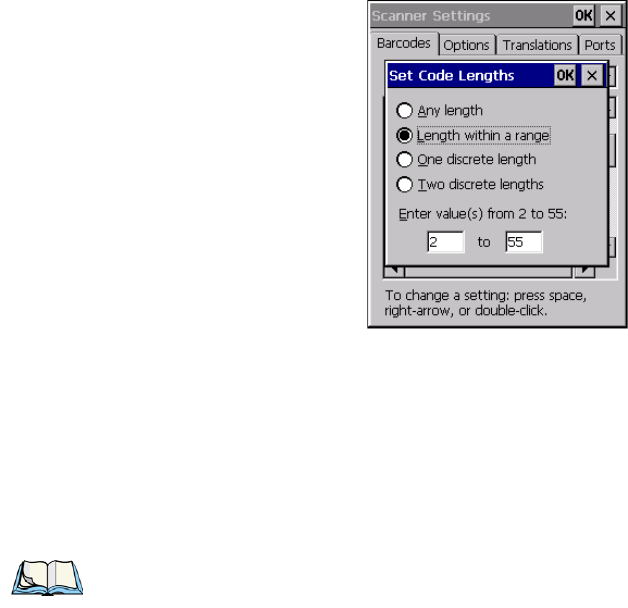
Psion Teklogix 7545 Hand-Held Computer User Manual C-13
Appendix C: Bar Code Settings
Decoded (Internal) Scanners
Code 39
Choosing One discrete length allows you to decode only those codes containing a selected
length. Choosing Two discrete lengths allows you to decode only those codes containing two
selected lengths. Length within a range allows you to decode a code type within a specified
range from 2 to 55.
Check Digit Verification
When this parameter is enabled, the integrity of a “Code 39” symbol is checked to ensure
that it complies with specified algorithms.
Transmit Check Digit
If the check digit is to be transmitted with the data, this parameter must be enabled.
Full ASCII
If this parameter is enabled, the characters +, %, and / are used as escape characters. The
combination of an escape character and the next character is converted to an equivalent
ASCII character.
Decode Performance
If this parameter is enabled, one of three decode levels can be chosen in the Decode Perfor-
mance Level parameter.
Note: Only those “Code 39” symbols that include a MOD 43 check digit are decoded
when this parameter is enabled.
Preliminary Draft 3
C-14 Psion Teklogix 7545 Hand-Held Computer User Manual
Appendix C: Bar Code Settings
Decoded (Internal) Scanners
Code 39
Decode Perf. Level
This parameter provides three levels of decode performance or “aggressiveness” for Code
39 symbols. Increasing the performance level reduces the amount of required bar code ori-
entation—this is useful when scanning very long and/or truncated bar codes. Keep in mind
that increased levels reduce decode security.
When you double-tap on this parameter, a dialog box is displayed in which you can enter a
decode performance level of between 1 and 3.
Length Restriction
The parameters in this sub-menu allow you to define the length of the bar codes that will be
decoded using either the Field Size parameter or the Minimum Size and Maximum Size pa-
rameters (see below). The order of operation to either match the Field Size or determine if
the length falls between the Minimum Size and Maximum Size is as follows:
• Strip the leading and trailing characters.
• Add the prefix and suffix characters.
• Count the number of characters remaining to either match the field size or determine if
the length falls between the minimum and maximum size.
Field Size
When a value is assigned for this parameter, only bar codes that match the field size exactly
can be transmitted. If a value is assigned to this parameter, a Minimum Size and Maximum
Size value is not required.
Minimum Size And Maximum Size
When a value is assigned to these parameters, only bar code lengths that fall between the
minimum and maximum value can be decoded. If values are assigned to these parameters, a
Field Size value is not required.
Add/Remove Data
Prefix Char
This character, if non-zero, is added before a successfully decoded bar code. Press the key
you want to insert in the dialog box attached to this parameter. The ASCII/Unicode key
value of the keypress is displayed.
Suffix Char
This character, if non-zero, is added after a successfully decoded bar code. Press the key you
want to insert in the dialog box attached to this parameter. The ASCII/Unicode key value of
the keypress is displayed.
Preliminary Draft 3

Psion Teklogix 7545 Hand-Held Computer User Manual C-15
Appendix C: Bar Code Settings
Decoded (Internal) Scanners
Code 128
Strip Leading
This parameter determines the number of characters that will be removed from the begin-
ning of the bar code before the prefix character is added.
Strip Trailing
The value entered in this parameter determines the number of characters that will be
removed from the end of the bar code before the suffix character is added.
C.2.6 Code 128
Enabled
Set this parameter to on to enable “Code 128”.
Enable GS1-128/GS1 US
Previously UPC/EAN and UCC, the GS1-128/GS1 US types of bar code include group sep-
arators and start codes.
Enable ISBT 128
To successfully scan this type of bar code, this option must be set to on.
Decode Performance
If this parameter is set to on, one of three decode levels assigned to the Decode Performance
Level parameter can be selected.
Decode Perf. Level
This parameter provides three levels of decode performance or “aggressiveness” for Code
128 symbols. Increasing the performance level reduces the amount of required bar code ori-
entation, allowing you to scan at an angle horizontal to the bar code. This is useful when
scanning very long and/or truncated bar codes. Keep in mind that increased levels reduce
decode security. There is a limitation that it can only be used with one fixed length.
When you double-tap on this parameter, a dialog box is displayed in which you can enter a
decode performance level of between 1 and 3.
Length Restriction
Refer to “Length Restriction” on page C-14 for details.
Note: For Code 39 bar codes, the “AIAG Strip” is performed before the “Strip Leading”.
Preliminary Draft 3
C-16 Psion Teklogix 7545 Hand-Held Computer User Manual
Appendix C: Bar Code Settings
Decoded (Internal) Scanners
EAN 13
Add/Remove Data
Refer to “Add/Remove Data” on page C-14 for details.
C.2.7 EAN 13
Enabled
Set this parameter to on to enable “EAN 13”.
Add/Remove Data
Refer to “Add/Remove Data” on page C-14 for details.
C.2.8 EAN 8
Enabled
Set this parameter to on to enable “EAN 8”.
EAN-8 Zero Extend
When this parameter is enabled, five leading zeros are added to decoded EAN-8 symbols,
making them compatible in format to EAN-13 symbols. Disabling this parameter returns
EAN-8 symbols to their normal format.
Add/Remove Data
Refer to “Add/Remove Data” on page C-14 for details.
C.2.9 UPC A
Enabled
Set this parameter to on to enable “UPC A”.
UPC-A, Check Digit
If you enable this parameter, the check digit is included with the decoded bar code data.
UPC-A, Preamble
When you double-tap on this parameter, a dialog box is displayed where you can choose one
of three options for lead-in characters for UPC-A symbols transmitted to the host device:
System Char—system character transmitted with the data,
Country Code and System Char—both the country code (“0” for USA) and system
character are transmitted with the data, or
Preliminary Draft 3
Psion Teklogix 7545 Hand-Held Computer User Manual C-17
Appendix C: Bar Code Settings
Decoded (Internal) Scanners
UPC E
None—no preamble is transmitted. The lead-in characters are considered part of
the symbol.
Add/Remove Data
Refer to “Add/Remove Data” on page C-14 for details.
C.2.10 UPC E
Enabled UPC-E
Set this parameter to on to allow “UPC E” bar code scans.
Enabled UPC-E1
Set this parameter to on to allow “UPC-E1” (zero suppressed) bar code scans.
UPC-E And UPC-E1 Check Digit
If you enable one or both of these parameters, a check digit is included with the decoded bar
code data.
UPC-E And UPC-E1 Preamble
When you double-tap on one of these parameters, a dialog box is displayed where you can
choose one of three options for lead-in characters for UPC-E and UPC-E1 symbols transmit-
ted to the host device:
System Char—system character transmitted with the data,
Country Code and System Char—both the country code (“0” for USA) and system
character are transmitted with the data, or
None—no preamble is transmitted. The lead-in characters are considered part of
the symbol.
Conv. UPC-E To UPC-A
This parameter converts UPC-E (zero suppressed) decoded data to UPC-A format before
transmission. After conversion, data follows UPC-A format and is affected by UPC-A pro-
gramming selections (e.g., Preamble, Check Digit).
Conv. UPC-E1 To UPC-A
This parameter converts UPC-E1 (zero suppressed) decoded data to UPC-A format before
transmission. After conversion, data follows UPC-A format and is affected by UPC-A pro-
gramming selections (e.g., Preamble, Check Digit).
Preliminary Draft 3
C-18 Psion Teklogix 7545 Hand-Held Computer User Manual
Appendix C: Bar Code Settings
Decoded (Internal) Scanners
UPC/EAN Shared Settings
Add/Remove Data
Refer to “Add/Remove Data” on page C-14 for details.
C.2.11 UPC/EAN Shared Settings
The parameters you set here are a shared across all available UPC and EAN bar codes.
Enable Bookland EAN
Setting this parameter to on allows your scanner to recognize Bookland EAN bar codes.
Supplementals
Supplementals are additionally appended characters (2 or 5).
Double-tapping this parameter displays a list of options. If Ignore is chosen, UPC/EAN is
decoded and the supplemental characters are ignored. If Decode is chosen, UPC/EAN
symbols are decoded with supplementals. Autodiscriminate works in conjunction with the
Supp. Redundancy parameter.
Supp. Redundancy
With “Autodiscriminate” selected in the Supplementals parameter, Supp. Redundancy
adjusts the number of times a symbol without supplementals is decoded before transmission.
When you double-tap on this parameter, a dialog is displayed in which you can enter a value
between 2 and 20. A value of 5 or above is recommended when Autodiscriminate is selected
and you are decoding a mix of UPC/EAN symbols with and without supplementals.
Security Level
This parameter controls the tolerance for decoding edge-to-edge UPC/EAN bar codes.
Double-tapping on this parameter displays a dialog box in which you can choose a level
from 0 to 3. Lower values have a lower tolerance for misreads, but they also increase the
time it takes to decode the bar code.
Linear Decode (Model SE2223)
Linear Decode applies to code types containing two adjacent blocks (e.g., UPC-A, EAN-8,
EAN-13). When enabled (set to on), a bar code is transmitted only when both the left and
right blocks are successfully decoded within one laser scan. This option should be enabled
when bar codes are in proximity to each other.
2D UPC Half Block Stitching (Model SE2223)
Setting this parameter to on enables “UPC Half Block Stitching” for the SE2223 omnidirec-
tional engine only.
Preliminary Draft 3
Psion Teklogix 7545 Hand-Held Computer User Manual C-19
Appendix C: Bar Code Settings
Decoded (Internal) Scanners
Code 93
C.2.12 Code 93
Enabled
Set this parameter to on to enable “Code 93”, or off to disable it.
Set Length L1 And Set Length L2
Lengths for “Code 93” can be set for Any Length, Length within a range, One discrete
length or Two discrete lengths. The length of a code refers to the number of characters
(i.e., human readable characters), including check digit(s).
Double-tapping on this parameter displays a dialog box labelled Set Code Lengths where
you can define the code length that will be recognized by your scanner.
Choosing One discrete length allows you to decode only those codes containing a selected
length. Choosing Two discrete lengths allows you to decode only those codes containing two
selected lengths. Length within a range allows you to decode a code type within a specified
range from 4 to 55.
Length Restriction
Refer to “Length Restriction” on page C-14 for details.
Add/Remove Data
Refer to “Add/Remove Data” on page C-14 for details.
C.2.13 Codabar
Enabled
Set this parameter to on to enable “Codabar”.
Set Length L1 And Set Length L2
Lengths for “Codabar” can be set for Any length, Length within a range, One discrete length
or Two discrete lengths. The length of a code refers to the number of characters (i.e., human
readable characters), including check digit(s).
Double-tapping on this parameter displays a dialog box labelled Set Code Lengths where
you can define the code length that will be recognized by your scanner.
Choosing One discrete length allows you to decode only those codes containing a selected
length. Choosing Two discrete lengths allows you to decode only those codes containing two
selected lengths. Length within a range allows you to decode a code type within a specified
range from 5 to 55.
Preliminary Draft 3

C-20 Psion Teklogix 7545 Hand-Held Computer User Manual
Appendix C: Bar Code Settings
Decoded (Internal) Scanners
MSI Plessey
CLSI Editing
When enabled, this parameter strips the start and stop characters and inserts a space after the
first, fifth, and tenth characters of a 14-character Codabar symbol.
NOTIS Editing
When enabled, this parameter strips the start and stop characters from decoded
Codabar symbol.
Length Restriction
Refer to “Length Restriction” on page C-14 for details.
Add/Remove Data
Refer to “Add/Remove Data” on page C-14 for details.
C.2.14 MSI Plessey
Enabled
Set this parameter to on to enable “MSI Plessey”.
Set Length L1 And Set Length L2
Lengths for “MSI Plessey” can be set for Any length, Length within a range, One discrete
length or Two discrete lengths. The length of a code refers to the number of characters (i.e.,
human readable characters), including check digit(s).
Double-tapping on this parameter displays a dialog box labelled Set Code Lengths where
you can define the code length that will be recognized by your scanner.
Choosing One discrete length allows you to decode only those codes containing a selected
length. Choosing Two discrete lengths allows you to decode only those codes containing two
selected lengths. Length within a range allows you to decode a code type within a specified
range from 6 to 55.
Check Digits
Double-tapping on this parameter displays a dialog box in which you can choose One or
Two check digit(s).
If this parameter is set to One, it is assumed that the last digit is a check digit. If “Check
Digits” is set to Two, it is assumed that the last two digits are check digits.
Note: Symbol length does not include start and stop characters.
Preliminary Draft 3

Psion Teklogix 7545 Hand-Held Computer User Manual C-21
Appendix C: Bar Code Settings
Decoded (Internal) Scanners
Interleaved 2 of 5
Transmit Check Digit
If this parameter is enabled, the check digit is included with the bar code data.
Check Digit Algorithm
When the Two MSI Plessey check digits option is selected, an additional verification is re-
quired to ensure integrity. Double-tapping on this parameter displays a dialog box in which
you can choose the algorithm to be used: MOD 10/MOD 11 or MOD 10/MOD 10.
Length Restriction
Refer to “Length Restriction” on page C-14 for details.
Add/Remove Data
Refer to “Add/Remove Data” on page C-14 for details.
C.2.15 Interleaved 2 of 5
Enabled
Set this parameter to on to enable “Interleaved 2 of 5”.
Set Length L1 And Set Length L2
Lengths for “Interleaved 2 of 5” can be set for Any length, Length within a range, One dis-
crete length or Two discrete lengths. The length of a code refers to the number of characters
(i.e., human readable characters), including check digit(s).
Double-tapping on this parameter displays a dialog box labelled Set Code Lengths where
you can define the code length that will be recognized by your scanner.
Choosing One discrete length allows you to decode only those codes containing a selected
length. Choosing Two discrete lengths allows you to decode only those codes containing two
selected lengths. Length within a range allows you to decode a code type within a specified
range from 4 to 14.
Check Digit Verification
When enabled, this parameter checks the integrity of an I 2 of 5 symbol to ensure it complies
with a specified algorithm: either USS (Uniform Symbology Specification) or OPCC (Opti-
cal Product Code Council).
Note: If Two check digits is selected, an MSI Plessey “Check Digit Algorithm” must also
be selected. See below for details.
Preliminary Draft 3
C-22 Psion Teklogix 7545 Hand-Held Computer User Manual
Appendix C: Bar Code Settings
Decoded (Internal) Scanners
Discrete 2 of 5
Transmit Check Digit
If this parameter is enabled, the check digit is included with the bar code data.
Convert To EAN 13
If this parameter is enabled, an I 2 of 5 bar code is converted to EAN 13.
Length Restriction
Refer to “Length Restriction” on page C-14 for details.
Add/Remove Data
Refer to “Add/Remove Data” on page C-14 for details.
C.2.16 Discrete 2 of 5
Enabled
Set this parameter to on to enable “Discrete 2 of 5”.
Set Length L1 And Set Length L2
Lengths for “Discrete 2 of 5” can be set for Any length, Length within a range, One discrete
length or Two discrete lengths. The length of a code refers to the number of characters (i.e.,
human readable characters), including check digit(s).
Double-tapping on this parameter displays a dialog box labelled Set Code Lengths where
you can define the code length that will be recognized by your scanner.
Choosing One discrete length allows you to decode only those codes containing a selected
length. Choosing Two discrete lengths allows you to decode only those codes containing two
selected lengths. Length within a range allows you to decode a code type within a specified
range from 1 to 12.
Length Restriction
Refer to “Length Restriction” on page C-14 for details.
Add/Remove Data
Refer to “Add/Remove Data” on page C-14 for details.
C.2.17 RSS Code (Reduced Space Symbology)
Enable
Setting any of these parameters to on enables “2D RSS Code” scanning capability.
Preliminary Draft 3

Psion Teklogix 7545 Hand-Held Computer User Manual C-23
Appendix C: Bar Code Settings
Decoded (Internal) Scanners
Composite
Enable RSS-14 (Reduced Space Symbology)
RSS-14 code can be either purely linear or split in half with one half stacked on top of the
other half. Stacking the code reduces the bar code length, and providing the nominal height
of the code is maintained, it can be omni-directionally scanned.
Enable RSS Limited
“RSS-Limited” is restricted, in that it can only encode 14 digit GTINs (global trade item
number) that begin with either a 0 or a 1. It is not stackable and is not designed to be read
omni-directionally.
Enable RSS Expanded
“RSS Expanded” uses the same application identifiers as UCC/EAN-128 codes but it can be
split into sections and stacked several rows high, reducing the length of the symbol, while
increasing the capacity of data that can be stored. “RSS Expanded” code can be omni-
directionally scanned.
Length Restriction
Refer to “Length Restriction” on page C-14 for details.
Add/Remove Data
Refer to “Add/Remove Data” on page C-14 for details.
C.2.18 Composite
A composite symbol includes multi-row 2D components making it compatible with linear
and area CCD scanners along with linear and rastering laser scanners. The options available
for this parameter represent multi-level components of a composite symbol.
Enable CC-C And Enable CC-AB
To activate these components, set the parameters to on.
Enable TLC-39
This composite component integrates MicroPDF417 with the linear code. Setting this pa-
rameter to on enables this parameter.
Important: To successfully read this type of bar code, the two types of symbologies
included in a composite bar code must be enabled. In addition, “Center Bar
Code Only” must be disabled (see page C-42).
Preliminary Draft 3
C-24 Psion Teklogix 7545 Hand-Held Computer User Manual
Appendix C: Bar Code Settings
Decoded (Internal) Scanners
PDF-417
C.2.19 PDF-417
Enabled
Setting this parameter to on enables PDF-417 two dimensional (2D) coding.
Length Restriction
Refer to “Length Restriction” on page C-14 for details.
Add/Remove Data
Refer to “Add/Remove Data” on page C-14 for details.
C.2.20 Micro PDF-417
Enabled
Setting this parameter to on enables “2D Micro PDF-417” bar code scanning. Micro PDF-
417 is a multi-row symbology that is useful for applications requiring greater area efficiency
but lower data capacity than PDF-417.
Code 128 Emulation
When this parameter is enabled, the scanner transmits data from certain Micro PDF-417
symbols as if it was encoded in Code 128 symbols.
If Code 128 Emulation is enabled, the following Micro PDF-417 symbols are transmitted
with one of the following prefixes:
]C1 if the first codeword is 903-907, 912, 914, 915
]C2 if the first codeword is 908 or 909
]C0 if the first codeword is 910 or 911
If Code 128 Emulation is set to off, the Micro PDF-417 symbols are transmitted with one of
the following prefixes:
]L3 if the first codeword is 903-907, 912, 914, 915
]L4 if the first codeword is 908 or 909
]L5 if the first codeword is 910 or 911
Length Restriction
Refer to “Length Restriction” on page C-14 for details.
Add/Remove Data
Refer to “Add/Remove Data” on page C-14 for details.
Preliminary Draft 3
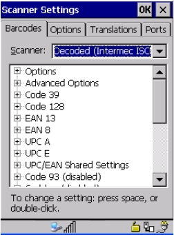
Psion Teklogix 7545 Hand-Held Computer User Manual C-25
Appendix C: Bar Code Settings
Decoded (Intermec ISCP)
Decoded (ISCP) Options
C.3 Decoded (Intermec ISCP)
• Tap on the Scanner drop-down menu, and choose Decoded (Intermec ISCP).
C.3.1 Decoded (ISCP) Options
Laser On Time
The value assigned to this parameter determines how long the laser will remain on when the
scan button or trigger is pressed.
Double-tapping on this parameter displays a dialog box in which you can enter a value
between 1 and 10 seconds.
C.3.2 Decoded (ISCP) Advanced Options
Continuous Scan Mode
Setting this parameter to on keeps the laser on and continuously decoding as long as the
scanner button is pressed and held down.
Minimum Cancel Time
The value assigned to this parameter determines the time delay before the scanner is turned
off, once the scanner trigger or button is released. This gives the scanner a minimum amount
of time to complete its current decode before the scan is cancelled when you quickly trigger
on/off.
Preliminary Draft 3

C-26 Psion Teklogix 7545 Hand-Held Computer User Manual
Appendix C: Bar Code Settings
Decoded (Intermec ISCP)
Code 39
Low Power Timeout
To extend laser life, you can select the time the scanner remains active following a success-
ful decode. The scanner wakes from low power mode when a bar code is scanned—a
successful decode restores normal blinking.
When you double-tap on this parameter, a dialog box is displayed in which you can choose a
value of 30 sec, 1 min, 2 min, or 3 min.
Parameter Scanning
Setting this parameter to Enabled allows decoding of parameter bar codes.
Same Read Validate
The data is only transmitted after repeated reads give the same result. The value assigned at
this parameter determines the number of reads required, from 0 to 10 times.
Same Read Timeout
Prevents the same bar code from being read more than once. The value assigned determines
after what time period the scanner will timeout, from 0 to 2550 msec.
Diff Read Timeout
Prevents unwanted reading of other bar codes on the same label. The value assigned deter-
mines after what time period the scanner will timeout, from 0 to 2550 msec.
Add AIM ID Prefix
The AIM ID (Association for Automatic Identification and Mobility) is an international bar
code identifier. When this parameter is enabled, the AIM ID is inserted at the beginning of
the decoded bar code.
C.3.3 Code 39
Enable
Setting this parameter to on enables “Code 39”.
Note: This parameter is only used if the Trigger Mode has been set to Continuous On and
the unit is mounted in a fixed position; otherwise, ‘Low Power Timeout’ is not used.
Preliminary Draft 3

Psion Teklogix 7545 Hand-Held Computer User Manual C-27
Appendix C: Bar Code Settings
Decoded (Intermec ISCP)
Code 39
Full ASCII
If this parameter is enabled, the characters +, %, and / are used as escape characters. The
combination of an escape character and the next character is converted to an equivalent
ASCII character.
Reading Range
Determines the reading distance from which a bar code can be successfully scanned. The
default setting, Extended, allows for increased reading distance.
Start/Stop Transmit
Setting this parameter to on enables the transmission of start and stop characters, which are
usually not transmitted. Code 39 can start and end with either a * or a $ character (see also
the next parameter).
Accepted Start Char
This parameter allows you the option of using one of the two start/stop characters or both ($
char, * char, $ and * char).
Check Digit Verification
Uses the specified algorithm of the option you've chosen to ensure the integrity of the
symbol data before transmitting. If the data does not contain that algorithm, the data is not
transmitted. The available options are: Disabled, MOD 43 Check, French CIP, or
Italian CIP.
Transmit Check Digit
If the check digit is to be transmitted with the data, this parameter must be enabled.
Minimum Length
Minimum lengths for the bar code can be set from 0 to 255. The length of a code refers to
the number of characters (i.e., human readable characters), including check digit(s).
Length Restriction
Refer to “Length Restriction” on page C-14 for details.
Note: French CIP (French pharmaceutical) is only used with bar codes containing
7 characters.
Italian CIP (Italian pharmaceutical) is also known as Code 32. It is transmitted as a
standard Code 39 if checksum is not validated.
Preliminary Draft 3

C-28 Psion Teklogix 7545 Hand-Held Computer User Manual
Appendix C: Bar Code Settings
Decoded (Intermec ISCP)
Code 128
Add/Remove Data
Refer to “Add/Remove Data” on page C-14 for details.
C.3.4 Code 128
Enabled
Setting this parameter to on enables “Code 128”.
GS1-128
“GS1-128” is the GS1 implementation of the Code 128 barcode specification. The former
correct name was UCC/EAN-128.
GS1-128 Identifier
“GS1-128 Identifier” allows the AIM ID " ]C1" for EAN 128 to be transmitted or removed.
By default, this identifier is transmitted if EAN 128 is enabled.
GTIN Compliant
GTIN (global trade item number) processing transmits EAN 128 as the 14-character
EAN/UCC GTIN. To use GTIN processing, you must activate the EAN 128 symbology.
FNC1 Conversion
“FNC1 Conversion” allows the FNC1 character to be converted to another character for ap-
plications that cannot use the default <GS> Group Separator or hex (1d).
Double-tapping on this option displays a dialog box listing the allowable range: 0 to 255.
Enable ISBT 128
To successfully scan this type of bar code (International Society of Blood Transfusion), this
option must be set to on. If you enable this type of bar code, Code 128/EAN 128 is deacti-
vated to avoid any confusion.
ISBT Concat Transmit
The codes are not concatenated by default. You need to choose one of the options provided
for this parameter to send concatenated code. Choosing Only Concatenated Codes transmits
only concatenated codes—single codes will not be transmitted. Choosing Concatenated or
Single transmits single codes or concatenated codes. If only one code of a pair is read, that
Important: When EAN 128 and GTIN processing are both activated, it is not possible
to read normal EAN 128 Codes.
Preliminary Draft 3

Psion Teklogix 7545 Hand-Held Computer User Manual C-29
Appendix C: Bar Code Settings
Decoded (Intermec ISCP)
EAN 13
code will be transmitted as a single code. If both codes in a pair are detected, they will be
concatenated provided that “ISBT Concat Any Pair” (see below) is enabled.
ISBT Concat Any Pair
Enabling this parameter causes all code pairs that can be, to be concatenated even if they do
not comply with Section 4.1 of the “ISBT 128 Bar Code Symbology and Application Speci-
fication for Labeling of Whole Blood and Blood Components” (June 2000, Version 1.2.1).
Reading Range
Determines the reading distance from which a bar code can be successfully scanned. The
default setting, Extended, allows for increased reading distance.
Check Digit Verification
The available options for this parameter are Disabled or French CIP. This parameter uses
the specified algorithm of the option you've chosen to ensure the integrity of the symbol data
before transmitting. If the data does not contain that algorithm, the data is not transmitted.
Minimum Length
Minimum lengths for the bar code can be set from 0 to 255. The length of a code refers to
the number of characters (i.e., human readable characters), including check digit(s).
Length Restriction
Refer to “Length Restriction” on page C-14 for details.
Add/Remove Data
Refer to “Add/Remove Data” on page C-14 for details.
C.3.5 EAN 13
Enabled
Set this parameter to on to enable “EAN 13”.
ISBN Conversion
When this parameter (International Standard Book Number) is enabled, the first 3 characters
(‘978’) are ignored and the checksum (0.9, ‘X’) is calculated on the remaining characters.
Note: French CIP (French pharmaceutical) is only used with bar codes containing
7 characters.
Preliminary Draft 3
C-30 Psion Teklogix 7545 Hand-Held Computer User Manual
Appendix C: Bar Code Settings
Decoded (Intermec ISCP)
EAN 8
Transmit Check Digit
If the check digit is to be transmitted with the data, this parameter must be enabled.
Add/Remove Data
Refer to “Add/Remove Data” on page C-14 for details.
C.3.6 EAN 8
Enabled
Set this parameter to on to enable “EAN 8”.
Transmit Check Digit
If the check digit is to be transmitted with the data, this parameter must be enabled.
Convert To EAN 13
If this parameter is enabled, an EAN 8 bar code is converted to EAN 13.
Add/Remove Data
Refer to “Add/Remove Data” on page C-14 for details.
C.3.7 UPC A
Enabled
Set this parameter to on to enable “UPC A” bar code scanning recognition.
Transmit Check Digit
If the check digit is to be transmitted with the data, this parameter must be enabled.
Transmit Number System
If this parameter is enabled, the number system digit is transmitted with the decoded bar
code data.
Convert To EAN 13
If this parameter is enabled, a UPC A bar code is converted to EAN 13.
Add/Remove Data
Refer to “Add/Remove Data” on page C-14 for details.
Preliminary Draft 3
Psion Teklogix 7545 Hand-Held Computer User Manual C-31
Appendix C: Bar Code Settings
Decoded (Intermec ISCP)
UPC E Settings
C.3.8 UPC E Settings
Enabled
Set this parameter to on to enable “UPC E”.
Enable UPC-E1
Set this parameter to on to allow “UPC-E1” (zero suppressed) bar code scans.
Transmit Check Digit
If the check digit is to be transmitted with the data, this parameter must be enabled.
Transmit Number System
If this parameter is enabled, the number system digit is transmitted with the decoded bar
code data.
Convert To UPC-A
This parameter converts UPC E (zero suppressed) decoded data to UPC A format before
transmission. After conversion, data follows UPC A format and is affected by UPC A pro-
gramming selections (e.g. Check Digit).
Add/Remove Data
Refer to “Add/Remove Data” on page C-14 for details.
C.3.9 UPC/EAN Shared Settings
The setting assigned to the “Addendum” parameter associated with this option is shared
across all UPC and EAN bar codes.
Addendum
An addendum is a separate bar code, supplementary to the main bar code. This parameter
provides two options: Not Required but Transmitted if Read or Required and Transmitted.
• Double-tap on Addendum to display a dialog box listing your options.
• Highlight an item, and tap on OK.
When “Addendum” is set to Not Required but Transmitted if Read, the scanner searches for
an addendum and if one exists, appends it to the main bar code. When the parameter is set to
Required and Transmitted, the scanner does not accept the main bar code without
an addendum.
Preliminary Draft 3

C-32 Psion Teklogix 7545 Hand-Held Computer User Manual
Appendix C: Bar Code Settings
Decoded (Intermec ISCP)
Code 93
Addendum Add-on 2 And Addendum Add-on 5
Enabling these parameters sets the length of the addendum bar code to either 2 or
5characters.
Addendum Security
If you tap on “Addendum Security”, a dialog box is displayed in which you can define the
security level of add-on 2 or add-on 5 with a value from 0 to 100. As security levels in-
crease, the scanner decode speed decreases.
GTIN Compliant
GTIN (global trade item number) processing transmits EAN 128 as the 14-character
EAN/UCC GTIN. To use GTIN processing, you must activate the EAN 128 symbology.
Reading Range
This parameter determines the reading distance from which a bar code can be successfully
scanned. The default setting, Extended, allows for increased reading distance.
C.3.10 Code 93
Enabled
Set this parameter to on to enable “Code 93”.
Minimum Length
Minimum lengths for the bar code can be set from 0 to 255. The length of a code refers to
the number of characters (i.e., human readable characters), including check digit(s).
Length Restriction
Refer to “Length Restriction” on page C-14 for details.
Add/Remove Data
Refer to “Add/Remove Data” on page C-14 for details.
Important: When EAN 128 and GTIN processing are both activated, it is not possible
to read normal EAN 128 Codes.
Preliminary Draft 3
Psion Teklogix 7545 Hand-Held Computer User Manual C-33
Appendix C: Bar Code Settings
Decoded (Intermec ISCP)
Codabar
C.3.11 Codabar
Enabled
Set this parameter to on to enable “Codabar”.
Start/Stop Transmit
Codabar can use the following sets of characters as start and stop characters:
a, b, c, d
A, B, C, D
a, b, c, d, /, t, n, *, e
DC1, DC2, DC3, DC4
Thus, when a set is chosen, the first and last digits of a Codabar message must be one of
those characters and the body of the message should not contain these characters. Setting
this parameter to Not Transmitted strips the start and stop characters from this bar code.
CLSI Library System
When enabled, spaces are inserted after characters 1, 5, 10 in the 14-character label (used in
the USA by libraries using the CLSI system).
Check Digit Verification
When enabled, this parameter checks the integrity of a symbol to ensure it complies with a
specified algorithm—either USS (Uniform Symbology Specification) or OPCC (Optical
Product Code Council).
Transmit Check Digit
If the check digit is to be transmitted with the data, this parameter must be enabled.
Set Length L1, Set Length L2, And Set Length L3
Lengths for “Codabar” can be set from 0 to 255. The length of a code refers to the number of
characters (i.e., human readable characters), including check digit(s).
Double-tapping on these parameters displays dialog boxes where you can define the code
length that will be recognized by your scanner.
Length Mode
You can choose to set L1 as Minimum Length or L1,L2,L3 as Fixed Length.
Preliminary Draft 3
C-34 Psion Teklogix 7545 Hand-Held Computer User Manual
Appendix C: Bar Code Settings
Decoded (Intermec ISCP)
MSI Plessey
Length Restriction
Refer to “Length Restriction” on page C-14 for details.
Add/Remove Data
Refer to “Add/Remove Data” on page C-14 for details.
C.3.12 MSI Plessey
Enabled
Set this parameter to on to enable “MSI”.
Enable Plessy
Set this parameter to on to enable “Plessy”.
Check Digit Verification
The available options for this parameter are MOD 10 Check and Double MOD 10 Check.
This parameter uses the specified algorithm of the option you've chosen to ensure the integ-
rity of the symbol data before transmitting. If the data does not contain that algorithm, the
data is not transmitted.
Transmit Check Digit
If the check digit is to be transmitted with the data, this parameter must be enabled.
Plessy Transmit Check Digit
If the check digit is to be transmitted with the Plessy data, this parameter must be enabled.
Minimum Length
Minimum lengths for the bar code can be set from 0 to 255. The length of a code refers to
the number of characters (i.e., human readable characters), including check digit(s).
Plessy Minimum Length
Minimum lengths for the Plessy bar code can be set from 0 to 255. The length of a code
refers to the number of characters (i.e., human readable characters), including check digit(s).
Length Restriction
Refer to “Length Restriction” on page C-14 for details.
Add/Remove Data
Refer to “Add/Remove Data” on page C-14 for details.
Preliminary Draft 3
Psion Teklogix 7545 Hand-Held Computer User Manual C-35
Appendix C: Bar Code Settings
Decoded (Intermec ISCP)
Code 11
C.3.13 Code 11
Enabled
Set this parameter to on to enable “Code 11”.
Check Digit Verification
The available options for this parameter are MOD 10 Check and Double MOD 10
Check.This parameter uses the specified algorithm of the option you've chosen to ensure the
integrity of the symbol data before transmitting. If the data does not contain that algorithm,
the data is not transmitted.
Transmit Check Digit
If the check digit is to be transmitted with the data, this parameter must be enabled.
Minimum Length
Minimum lengths for the bar code can be set from 0 to 255. The length of a code refers to
the number of characters (i.e., human readable characters), including check digit(s).
Length Restriction
Refer to “Length Restriction” on page C-14 for details.
Add/Remove Data
Refer to “Add/Remove Data” on page C-14 for details.
C.3.14 Interleaved 2 of 5
Enabled
Set this parameter to on to enable “Interleaved 2 of 5”.
Reading Range
This parameter determines the reading distance from which a bar code can be successfully
scanned. The default setting, Extended, allows for increased reading distance.
Check Digit Verification
The available options for this parameter are Disabled, MOD 10 Check and French CIP.
“Check Digit Verification” uses the specified algorithm of the option you've chosen to
ensure the integrity of the symbol data before transmitting. If the data does not contain that
algorithm, the data is not transmitted.
Preliminary Draft 3

C-36 Psion Teklogix 7545 Hand-Held Computer User Manual
Appendix C: Bar Code Settings
Decoded (Intermec ISCP)
Matrix 2 of 5
Transmit Check Digit
If the check digit is to be transmitted with the data, this parameter must be enabled.
Set Length L1, Set Length L2, And Set Length L3
Lengths for “Interleaved 2 of 5” can be set from 0 to 255. The length of a code refers to the
number of characters (i.e., human readable characters), including check digit(s).
Double-tapping on these parameters displays dialog boxes where you can define the code
length that will be recognized by your scanner.
Length Mode
You can chose to set L1 as Minimum Length or L1,L2,L3 as Fixed Length.
Length Restriction
Refer to “Length Restriction” on page C-14 for details.
Add/Remove Data
Refer to “Add/Remove Data” on page C-14 for details.
C.3.15 Matrix 2 of 5
Enabled
Set this parameter to on to enable “Matrix 2 of 5”.
Minimum Length
Minimum lengths for the bar code can be set from 0 to 255. The length of a code refers to
the number of characters (i.e., human readable characters), including check digit(s).
Length Restriction
Refer to “Length Restriction” on page C-14 for details.
Add/Remove Data
Refer to “Add/Remove Data” on page C-14 for details.
Note: French CIP (French pharmaceutical) is only used with bar codes containing
7 characters.
Preliminary Draft 3
Psion Teklogix 7545 Hand-Held Computer User Manual C-37
Appendix C: Bar Code Settings
Decoded (Intermec ISCP)
Discrete 2 of 5
C.3.16 Discrete 2 of 5
Enabled
Set this parameter to on to enable “Discrete 2 of 5”.
Standard 2 of 5 Format
This parameter allows you to choose a standard format – either Identicon (6 start/stop bars)
or Computer Identics (4 start/stop bars).
Check Digit Verification
The available options for this parameter are Disabled and MOD 10 Check. “Check Digit
Verification” uses the specified algorithm of the option you've chosen to ensure the integrity
of the symbol data before transmitting. If the data does not contain that algorithm, the data is
not transmitted.
Transmit Check Digit
If the check digit is to be transmitted with the data, this parameter must be enabled.
Set Length L1, Set Length L2, And Set Length L3
Lengths for “Discrete 2 of 5” can be set from 0 to 255. The length of a code refers to the
number of characters (i.e., human readable characters), including check digit(s).
Double-tapping on these parameters displays dialog boxes where you can define the code
length that will be recognized by your scanner.
Length Mode
You can chose to set L1 as Minimum Length or L1,L2,L3 as Fixed Length.
Length Restriction
Refer to “Length Restriction” on page C-14 for details.
Add/Remove Data
Refer to “Add/Remove Data” on page C-14 for details.
C.3.17 Telepen
Enabled
Set this parameter to on to enable “Telepen”.
Preliminary Draft 3
C-38 Psion Teklogix 7545 Hand-Held Computer User Manual
Appendix C: Bar Code Settings
Decoded (Intermec ISCP)
RSS Code (Reduced Space Symbology)
Format
This parameter allows you to set the bar code character format to either ASCII or Numeric.
Minimum Length
Minimum lengths for the bar code can be set from 0 to 255. The length of a code refers to
the number of characters (i.e., human readable characters), including check digit(s).
Length Restriction
Refer to “Length Restriction” on page C-14 for details.
Add/Remove Data
Refer to “Add/Remove Data” on page C-14 for details.
C.3.18 RSS Code (Reduced Space Symbology)
Enable
Setting this parameter to on enables “RSS Code” scanning capability.
Enable RSS-14
RSS-14 code can be either purely linear or split in half with one half stacked on top of the
other half. Stacking the code reduces the bar code length, and providing the nominal height
of the code is maintained, it can be omni-directionally scanned.
Enable RSS Limited
‘RSS-Limited” is restricted, in that it can only encode 14 digit GTINs (global trade item
numbers) that begin with either 0 or 1. It is not stackable and is not designed to be read
omni-directionally.
Enable RSS Expanded
‘RSS Expanded” uses the same application identifiers as UCC/EAN-128 codes but they can
be split into sections and stacked several rows high, reducing the length of the symbol, while
increasing the capacity of data that can be stored. “RSS Expanded” code can be omni-direc-
tionally scanned.
Length Restriction
Refer to “Length Restriction” on page C-14 for details.
Add/Remove Data
Refer to “Add/Remove Data” on page C-14 for details.
Preliminary Draft 3

Psion Teklogix 7545 Hand-Held Computer User Manual C-39
Appendix C: Bar Code Settings
Decoded (Intermec ISCP)
Composite
C.3.19 Composite
A composite symbol includes multi-row 2D components making it compatible with linear
and area CCD scanners along with linear and rastering laser scanners.
The options available for this parameter represent multi-level components of a
composite symbol.
Enable CC-C And Enable CC-AB
To activate these components, set these parameters to on.
Linear Transmission Only
When Linear Transmission Only is enabled, only the linear code portion of the composite
bar code is transmitted when scanned.
UPC-EAN Composite Message
This option allows you to choose how UPC-EAN shared bar codes are transmitted: Always
Linked, Never Linked or Auto-discriminate.
C.3.20 TLC-39
Enabled
This composite component integrates MicroPDF417 with the linear Code 39 symbol.
Setting this parameter to on enables this parameter.
Linear Transmission Only
When Linear Transmission Only is enabled, only the linear portion of the composite bar
code is transmitted when scanned.
Security Level
This parameter is used to differentiate between TLC-39 and standard Code 39. Tapping on
Security Level displays a dialog box in which you can assign a value from 0 to 100. The
higher the value assigned, the lower the decode rate.
Length Restriction
Refer to “Length Restriction” on page C-14 for details.
Important: To successfully read this type of bar code, the two types of symbologies
included in a composite bar code must be enabled. In addition, “Center Bar
Code Only” must be disabled (see page C-42).
Preliminary Draft 3
C-40 Psion Teklogix 7545 Hand-Held Computer User Manual
Appendix C: Bar Code Settings
Decoded (Intermec ISCP)
PDF-417
Add/Remove Data
Refer to “Add/Remove Data” on page C-14 for details.
C.3.21 PDF-417
Enabled
Set this parameter to on to enable “2D PDF-417”.
Length Restriction
Refer to “Length Restriction” on page C-14 for details.
Add/Remove Data
Refer to “Add/Remove Data” on page C-14 for details.
C.3.22 Micro PDF-417
Enabled
Set this parameter to on to enable “2D Micro PDF-417”.
Code 128 Emulation
When this parameter is enabled, the scanner transmits data from certain Micro PDF-417
symbols as if it was encoded in Code 128 symbols.
If Code 128 Emulation is enabled, the following Micro PDF-417 symbols are transmitted
with one of the following prefixes:
]C1 if the first codeword is 903-907, 912, 914, 915
]C2 if the first codeword is 908 or 909
]C0 if the first codeword is 910 or 911
If Code 128 Emulation is set to off, the Micro PDF-417 symbols are transmitted with one of
the following prefixes:
]L3 if the first codeword is 903-907, 912, 914, 915
]L4 if the first codeword is 908 or 909
]L5 if the first codeword is 910 or 911
Length Restriction
Refer to “Length Restriction” on page C-14 for details.
Preliminary Draft 3
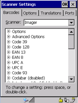
Psion Teklogix 7545 Hand-Held Computer User Manual C-41
Appendix C: Bar Code Settings
Imager
Codablock
Add/Remove Data
Refer to “Add/Remove Data” on page C-14 for details.
C.3.23 Codablock
Enable Codablock A
Set this parameter to on to enable “Codablock type A”.
Enable Codablock F
Set this parameter to on to enable “Codablock type F”.
Length Restriction
Refer to “Length Restriction” on page C-14 for details.
Add/Remove Data
Refer to “Add/Remove Data” on page C-14 for details.
C.4 Imager
• Tap on the Scanner drop-down menu, and choose Imager.
C.4.1 Imager Options
Tek I ma g e r E nab led
Setting this option to on enables the imager installed in your hand-held.
Preliminary Draft 3

C-42 Psion Teklogix 7545 Hand-Held Computer User Manual
Appendix C: Bar Code Settings
Imager
Imager Options
Continuous Scan Mode
Setting this parameter to on keeps image capture active and continuously decoding as long
as the scanner button is pressed and held down.
Center Barcode Only
When more than one bar code is visible in a single snap shot, this parameter allows you to
specify that only the centre image within the imager framing marker be read. When this pa-
rameter is set to on, the target dot is pointed at the centre image and only that image is
returned.
Max Number Barcodes
Specifies the maximum number of bar codes the imager attempts to decode in an image. A
maximum of 6 bar codes can be decoded at one time.
Barcodes Must Decode
This parameter specifies the minimum number of bar codes that the imager must decode in
order to report success.
Window Width
“Window Width” determines the width of the captured image in pixels.
Window Height
This parameter determines the height of the captured image in pixels.
Note: This parameter must be disabled when reading Composite bar codes.
Note: This number must be less than the number of bar codes assigned to Max Number
Barcodes. The driver validates and reassigns the value if necessary.
Note: The driver will validate and reassign the value assigned to this parameter, if neces-
sary; the driver will also use the Window Width value to horizontally center the
image in the field of view.
Note: The driver will validate and reassign the value assigned to this parameter, if neces-
sary; the driver will also use Window Height value to vertically center the image in
the field of view.
Preliminary Draft 3

Psion Teklogix 7545 Hand-Held Computer User Manual C-43
Appendix C: Bar Code Settings
Imager
Imager Advanced Options
Dot Time (msec)
The value selected for “Dot Time (msec)” determines (in milliseconds) how long the target-
ing dot remains on before the scanner begins capturing images. When you double-tap on this
parameter, a dialog box is displayed in which you can enter a value of between 0 and 3000.
A value of 0 disables the target dot.
C.4.2 Imager Advanced Options
Factory Defaults On Reboot
The value assigned to this parameter determines whether or not the driver will restore the
factory defaults to the imager device on the next reboot.
Min Scan Duration
This parameter defines the minimum amount of time in seconds that the imager will scan
when the trigger is pressed and held down without successful decode.
Captures Per HW Trigger
The value assigned to this parameter determines the number of captures the imager device
will take while the imager's internal hardware trigger is held down.
Important: Do not adjust the advanced options without first consulting Psion Teklogix
technical support.
Note: The driver will default the imager device on a ‘clean’ reset, regardless of the value
of this parameter.
Note: The actual scan duration when the trigger is pressed relies on the value assigned to
“Captures Per HW Trigger”, below.
Note: This parameter, together with “Min Scan Duration”, determines the actual scan
duration. When the scan trigger is pressed and held down, the driver starts a timer
based on the value of “Min Scan Duration” and also sends a command to emulate
the hardware trigger. When completed, if the time has not yet expired, it will send
another command to the imager device, forcing the imager to flash again using the
value assigned to “Captures Per HW Trigger”.
Preliminary Draft 3

C-44 Psion Teklogix 7545 Hand-Held Computer User Manual
Appendix C: Bar Code Settings
Imager
Imager Advanced Options
Auto Exposure
Setting this parameter to on allows the imager to make automatic gain, integration and illu-
mination adjustments based on ambient light before capturing the bar code. If the
adjustment is insufficient, further adjustments are made automatically before another image
is captured.
Fast Converge
Setting this parameter to on speeds the “Auto Exposure” process. It allows the imager to
rapidly snap a number of bar code capture attempts while finding ideal values for gain, inte-
gration and illumination.
Max Gain, Max Integration And Max Illumination
These parameters represent internal values used by the 2D imager. The “Auto Exposure” pa-
rameter automatically adjusts the Max Gain, Max Integration and Max Illumination
parameters to produce the best bar code read. Keep in mind that “Auto Exposure” must be
set to on in order for these parameter values to be automatically adjusted.
Double-tapping on any of these parameters displays an associated dialog box in which an al-
lowable range is displayed: Max Gain – 357 to 7920, Max Integration – 0 to 65535,
Max Illumination – 0 to 7.
Decoder Timeout
The decoder is a set of algorithms that examine the image and attempt to find the bar codes,
and then turn the pixels into data that the computer can use—this process takes time. “De-
coder Timeout” limits the amount of time the decoder will spend attempting to decode an
image, and forces it to stop and grab a new image, which will probably be easier to decode.
Important: This parameter value should only be changed by qualified Psion Teklogix
personnel. It should be left at the default value: on.
Note: “Auto Exposure” must be set to on in order for this parameter to function.
Keep in mind that while this parameter can improve imager performance, “Fast
Converge” increases battery power consumption.
Important: These parameter values should only be changed by qualified Psion
Teklogix personnel.
Preliminary Draft 3

Psion Teklogix 7545 Hand-Held Computer User Manual C-45
Appendix C: Bar Code Settings
Imager
Code 39
Adaptive Windowing
“Adaptive Windowing” is an advanced technique used to speed up bar code recognition in
certain applications. This parameter automatically reduces the size of the window to the
user-programmed window size when it successfully decodes (which reduces decode time
the next time it is used), but increases it to the full size window on a failed decode.
Constant Illumination
“Constant Illumination” is used to reduce the intrusiveness of the device’s illumination on
the observer. Instead of the illumination turning on and off every time the device attempts a
decode (2-4 times per second), the illumination stays on from the time the trigger is pulled
until a decode is successful. This feature is useful in low light environments, since it will
also reduce the distraction that the illumination can have on nearby co-workers.
C.4.3 Code 39
Enabled
Set this parameter to on to enable “Code 39”.
Full ASCII
If this parameter is enabled, the characters +, %, and / are used as escape characters. The
combination of an escape character and the next character is converted to an equivalent
ASCII character.
Check Digit Verification
When this parameter is enabled, the integrity of a “Code 39” symbol is checked to ensure
that it complies with specified algorithms.
Note: When decoding multiple bar codes in one image, the value assigned to ‘Decoder
Timeout’ should be increased to 200ms/extra bar code after the first.
Note: This feature assumes that you have reached an understanding about how the device
operates in your application, and that, after a learning period, operators will get
used to using the imager in one particular way. It also assumes that a trained oper-
ator will usually only have near miss scenarios.
Note: Only those “Code 39” symbols that include a MOD 43 check digit are decoded
when this parameter is enabled.
Preliminary Draft 3

C-46 Psion Teklogix 7545 Hand-Held Computer User Manual
Appendix C: Bar Code Settings
Imager
Code 128
Include Check
If this parameter is enabled, the check digit is included with the decoded bar code data.
Length Restriction
Refer to “Length Restriction” on page C-14 for details.
Add/Remove Data
Refer to “Add/Remove Data” on page C-14 for details.
C.4.4 Code 128
Enabled
Set this parameter to on to enable “Code 128.
Length Restriction
Refer to “Length Restriction” on page C-14 for details.
Add/Remove Data
Refer to “Add/Remove Data” on page C-14 for details.
C.4.5 EAN 13
Enabled
Set this parameter to on to enable “EAN 13”.
Addendum
An addendum is a separate bar code, supplementary to the main bar code. This parameter
provides three options: Disabled, Optional and Required. Depending on the value chosen
for this parameter, an addendum is recognized or ignored.
• Double-tap on Addendum to display a dialog box listing your options.
• Highlight an item, and tap on OK.
When “Addendum” is set to Disabled, the scanner does not recognize an addendum. If this
parameter is set to Optional, the scanner searches for an addendum and if one exists,
appends it to the main bar code. When the parameter is set to Required, the scanner does not
accept the main bar code without an addendum.
Note: Setting “Addendum” to ‘Optional’ reduces performance. It should only be chosen if
at least some of the bar codes being read have addendums.
Preliminary Draft 3
Psion Teklogix 7545 Hand-Held Computer User Manual C-47
Appendix C: Bar Code Settings
Imager
EAN 8
Add/Remove Data
Refer to “Add/Remove Data” on page C-14 for details.
C.4.6 EAN 8
Enabled
Set this parameter to on to enable “EAN 8”.
Addendum
Refer to “Addendum” on page 46.
Add/Remove Data
Refer to “Add/Remove Data” on page C-14 for details.
C.4.7 UPC A
Enabled
Set this parameter to on to enable “UPC A”.
Addendum
Refer to “Addendum” on page 46.
Add/Remove Data
Refer to “Add/Remove Data” on page C-14 for details.
C.4.8 UPC E
Enabled
Set this parameter to on to enable “UPC E”.
Addendum
Refer to “Addendum” on page 46.
Add/Remove Data
Refer to “Add/Remove Data” on page C-14 for details.
Preliminary Draft 3
C-48 Psion Teklogix 7545 Hand-Held Computer User Manual
Appendix C: Bar Code Settings
Imager
Code 93
C.4.9 Code 93
Enabled
Set this parameter to on to enable “Code 93”.
Length Restriction
Refer to “Length Restriction” on page C-14 for details.
Add/Remove Data
Refer to “Add/Remove Data” on page C-14 for details.
C.4.10 Codabar
Enabled
Set this parameter to on to enable “Codabar”.
Length Restriction
Refer to “Length Restriction” on page C-14 for details.
Add/Remove Data
Refer to “Add/Remove Data” on page C-14 for details.
C.4.11 Interleaved 2 of 5
Enabled
Set this parameter to on to enable “Interleaved 2 of 5”.
Check Digit Verification
When enabled, this parameter checks the integrity of an I 2 of 5 symbol to ensure it complies
with a specified algorithm – either USS (Uniform Symbology Specification) or OPCC (Op-
tical Product Code Council).
Include Check
If this parameter is enabled, the check digit is transmitted along with the I 2 of 5 symbol.
Length Restriction
Refer to “Length Restriction” on page C-14 for details.
Preliminary Draft 3

Psion Teklogix 7545 Hand-Held Computer User Manual C-49
Appendix C: Bar Code Settings
Imager
RSS Code (Reduced Space Symbology)
Add/Remove Data
Refer to “Add/Remove Data” on page C-14 for details.
C.4.12 RSS Code (Reduced Space Symbology)
Enable
Setting this parameter to on enables “RSS Code” scanning capability.
Length Restriction
Refer to “Length Restriction” on page C-14 for details.
Add/Remove Data
Refer to “Add/Remove Data” on page C-14 for details.
C.4.13 Composite
A composite symbol includes multi-row 2D components making it compatible with linear
and area CCD scanners along with linear and rastering laser scanners.
Enabled
Set this parameter to on to enable “Composite” bar code scanner.
C.4.14 PDF-417
Enabled
Setting this parameter to on enables PDF-417 two dimensional (2D) coding.
Length Restriction
Refer to “Length Restriction” on page C-14 for details.
Add/Remove Data
Refer to “Add/Remove Data” on page C-14 for details.
Important: To successfully read this type of bar code, the two types of symbologies
included in the composite must be enabled. In addition, “Center Barcode
Only” must be disabled (see page C-42).
Preliminary Draft 3
C-50 Psion Teklogix 7545 Hand-Held Computer User Manual
Appendix C: Bar Code Settings
Imager
Micro PDF-417
C.4.15 Micro PDF-417
Enabled
Setting this parameter to on enables “Micro PDF-417” bar code scanning. Micro PDF-417 is
a multi-row symbology that is useful for applications requiring greater area efficiency but
lower data capacity than PDF-417.
Length Restriction
Refer to “Length Restriction” on page C-14 for details.
Add/Remove Data
Refer to “Add/Remove Data” on page C-14 for details.
C.4.16 2D Data Matrix
Enabled
Set this parameter to on to enable “2D Data Matrix”.
Inverse Video Mode
Enabling this parameter allows the imager to read inverse bar codes—white symbols pre-
sented on a black background.
Rectangular
Enabling this parameter allows the imager to recognize rectangular (as opposed to square)
symbols.
Length Restriction
Refer to “Length Restriction” on page C-14 for details.
Add/Remove Data
Refer to “Add/Remove Data” on page C-14 for details.
C.4.17 2D QR Code
Enabled
Set this parameter to on to enable “2D QR Code”.
Preliminary Draft 3
Psion Teklogix 7545 Hand-Held Computer User Manual C-51
Appendix C: Bar Code Settings
Imager
2D Maxicode
Inverse Video Mode
Enabling this parameter allows the imager to read inverse bar codes—white symbols pre-
sented on a black background.
Length Restriction
Refer to “Length Restriction” on page C-14 for details.
Add/Remove Data
Refer to “Add/Remove Data” on page C-14 for details.
C.4.18 2D Maxicode
Enabled
Set this parameter to on to enable “2D Maxicode”.
Length Restriction
Refer to “Length Restriction” on page C-14 for details.
Add/Remove Data
Refer to “Add/Remove Data” on page C-14 for details.
C.4.19 2D Aztec
Enabled
Set this parameter to on to enable “Aztec”.
Length Restriction
Refer to “Length Restriction” on page C-14 for details.
Add/Remove Data
Refer to “Add/Remove Data” on page C-14 for details.
C.4.20 Postal: PlaNET
Enabled
Set this parameter to on to enable “Postal: PlaNET”.
Preliminary Draft 3
C-52 Psion Teklogix 7545 Hand-Held Computer User Manual
Appendix C: Bar Code Settings
Imager
Postal: PostNET
Length Restriction
Refer to “Length Restriction” on page C-14 for details.
Add/Remove Data
Refer to “Add/Remove Data” on page C-14 for details.
C.4.21 Postal: PostNET
Enabled
Set this parameter to on to enable “Postal: PostNET”.
Length Restriction
Refer to “Length Restriction” on page C-14 for details.
Add/Remove Data
Refer to “Add/Remove Data” on page C-14 for details.
C.4.22 Postal: Australian
Enabled
Set this parameter to on to enable “Postal: Australian”.
Length Restriction
Refer to “Length Restriction” on page C-14 for details.
Add/Remove Data
Refer to “Add/Remove Data” on page C-14 for details.
C.4.23 Postal: Japanese
Enabled
Set this parameter to on to enable “Postal: Japanese”.
Length Restriction
Refer to “Length Restriction” on page C-14 for details.
Add/Remove Data
Refer to “Add/Remove Data” on page C-14 for details.
Preliminary Draft 3
Psion Teklogix 7545 Hand-Held Computer User Manual C-53
Appendix C: Bar Code Settings
Imager
Postal: Korean
C.4.24 Postal: Korean
Enabled
Set this parameter to on to enable “Postal: Korean”.
Length Restriction
Refer to “Length Restriction” on page C-14 for details.
Add/Remove Data
Refer to “Add/Remove Data” on page C-14 for details.
C.4.25 Postal: Royal
Enabled
Set this parameter to on to enable “Postal: Royal”.
Length Restriction
Refer to “Length Restriction” on page C-14 for details.
Add/Remove Data
Refer to “Add/Remove Data” on page C-14 for details.
C.4.26 Postal: Kix
Enabled
Set this parameter to on to enable “Postal: Kix”.
Length Restriction
Refer to “Length Restriction” on page C-14 for details.
Add/Remove Data
Refer to “Add/Remove Data” on page C-14 for details.
C.4.27 Postal: Canadian
Enabled
Set this parameter to on to enable “Postal: Canadian”.
Preliminary Draft 3
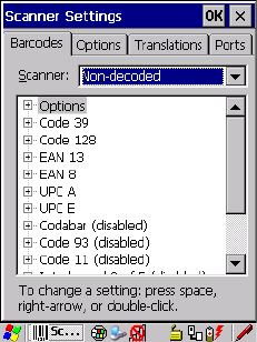
C-54 Psion Teklogix 7545 Hand-Held Computer User Manual
Appendix C: Bar Code Settings
Non-Decoded Scanners
Postal: Canadian
Length Restriction
Refer to “Length Restriction” on page C-14 for details.
Add/Remove Data
Refer to “Add/Remove Data” on page C-14 for details.
C.5 Non-Decoded Scanners
Figure C.1 Non-Decoded Scanner Options
• Tap on the Scanner drop-down menu, and choose Non-decoded.
All the available bar code symbologies for this type of scanner can be selected in this tab.
A ‘plus’ sign (+) to the left of the menu item indicates that a sub-menu of parameters is
attached.
• Tap the stylus on the + sign to display the sub-menu.
• To change a parameter value, double-tap on the parameter. If you need to type a value, a
dialog box is displayed in which you can type a new value. If you need to change a yes
or no value, double-tapping on the parameter toggles between yes and no.
If you’re using the keyboard:
• Highlight the bar code you want to work with, and press the [RIGHT] arrow key to
display the sub-menu.
• Use the [UP] and [DOWN] arrow keys to highlight a parameter.
• To change a parameter value, press [SPACE] or the [RIGHT] arrow key. If a field
requires text entry, a text box is displayed in which you can enter the appropriate value.
Preliminary Draft 3
Psion Teklogix 7545 Hand-Held Computer User Manual C-55
Appendix C: Bar Code Settings
Non-Decoded Scanners
Options
C.5.1 Options
• Tap the stylus on the + sign next to Options to display these parameters.
Dot Time (msec)
The value selected for “Dot Time (msec)” determines (in milliseconds) how long the target-
ing dot remains on before the scanner switches to a normal scan sweep. When you double-
tap on this parameter, a dialog box is displayed in which you can enter a value from 0 to
3000. A value of 0 (zero) disables the target dot.
Short Code
When enabled, this parameter allows scanning of short I 2 of 5 bar codes (2 characters).
When disabled, these short bar codes are rejected.
Enabling “Short Code” may reduce the robustness of the decoding since the hand-held must
decode more potential bar codes; it is therefore not recommended for general-purpose bar
codes with 4 or more characters.
Verify
The value entered for this parameter determines the number of correct additional decodes re-
quired after the initial decode, prior to a bar code being accepted. Higher values significantly
increase the time it takes to decode a bar code but also improve the reliability of the decoded
bar code.
Security
This parameter controls the tolerance for decoding edge-to-edge bar codes (Code 93, Code
128, UPC/EAN). Lower values have a lower tolerance for misreads, but they also increase
the time it takes to decode the bar code. The default value of 30 is generally a good compro-
mise setting.
C.5.2 Code 39
Enabled
Set this parameter to on to enable “Code 39” or off to disable it.
Full ASCII
If this parameter is enabled, the characters +, %, and / are used as escape characters. The
combination of an escape character and the next character is converted to an equivalent
ASCII character.
Preliminary Draft 3

C-56 Psion Teklogix 7545 Hand-Held Computer User Manual
Appendix C: Bar Code Settings
Non-Decoded Scanners
Code 39
Include Check
If this parameter is enabled, the check digit is included with the decoded bar code data.
AIAG Strip
If this parameter is enabled, the AIAG data identifier is removed from each decoded Code
39 label. The data identifier occurs in the first position next to the Code 39 start character. It
can be a single alphabetic character or a series of numeric digits followed by an alphabetic
character. This identifier defines the general category or specific use of the data contained in
the rest of the bar code.
Error Accept
If the “Err Accept” and “AIAG Strip” parameters are enabled, all label data without an
AIAG identifier character is accepted. If the “Err Accept” parameter is disabled and the
“AIAG Strip” parameter is enabled, the label data is not accepted.
MOD Checks
This parameter allows you to choose the check digit calculated: MOD 43 Check, MOD 10
Check or None.
• Double-tap on MOD Checks to display your options.
• Tap on a check digit to highlight it, and tap on OK.
If you choose None, a check is not executed.
Transmit Code ID Char
A code ID character identifies the scanned bar code type. In addition to any single character
prefix already selected, the code ID character is inserted between the prefix and the decoded
symbol.
Length Restriction
Refer to “Length Restriction” on page C-14 for details.
Add/Remove Data
Refer to “Add/Remove Data” on page C-14 for details.
Note: If your unit is operating with the Psion Teklogix TESS application, this parameter
should not be used in conjunction with the TESS AIAG feature. This is because the
hand-held performs the strip function before it processes the data through the AIAG
feature; if the prefix is stripped, the data is not identified as AIAG.
Preliminary Draft 3

Psion Teklogix 7545 Hand-Held Computer User Manual C-57
Appendix C: Bar Code Settings
Non-Decoded Scanners
Code 128
C.5.3 Code 128
Enabled
Set this parameter to on to enable “Code 128” or off to disable it.
Include Sym
Setting “Include Sym” to on causes the group separator(s) and start code contained in this
type of bar code to be displayed on the screen.
Variations
When using Code 128, you can choose the bar code variation the scanner will recognize.
The options available are Standard, UCC 128 and EAN/UCC 128.
• Double-tap on Variations to display a dialog box listing your options.
• Tap on a variation to highlight it, and then tap on OK.
If you choose None, a check is not executed.
Standard
Enable Standard if “Code 128” is desired.
UCC 128
UCC 128 is a variation of “Code 128”.
EAN/UCC 128
To successfully scan this type of bar code, “EAN/UCC 128” must be enabled. “EAN/UCC”
bar codes include group separators and start codes.
Transmit Code ID Char
A code ID character identifies the scanned bar code type. In addition to any single character
prefix already selected, the code ID character is inserted between the prefix and the decoded
symbol.
Length Restriction
Refer to “Length Restriction” on page C-14 for details.
Note: This option is available only when ‘EAN/UCC 128’ is selected.
Preliminary Draft 3

C-58 Psion Teklogix 7545 Hand-Held Computer User Manual
Appendix C: Bar Code Settings
Non-Decoded Scanners
EAN 13
Add/Remove Data
Refer to “Add/Remove Data” on page C-14 for details.
C.5.4 EAN 13
Enabled
Set this parameter to on to enable “EAN 13” or off to disable it.
Enable Bookland EAN
Setting this parameter to on allows your scanner to recognize Bookland EAN bar codes.
Include Country
If this parameter is enabled, the country code is included with the decoded bar code data.
Include Check
If this parameter is enabled, the check digit is included with the decoded bar code data.
Addendum
An addendum is a separate bar code, supplementary to the main bar code. This parameter
provides three options: Disabled, Optional and Required. Depending on the value chosen for
this parameter, an addendum is recognized or ignored.
• Double-tap on Addendum to display a dialog box listing your options.
• Highlight an item, and tap on OK.
When “Addendum” is set to Disabled the scanner does not recognize an addendum. If this
parameter is set to Optional the scanner searches for an addendum and if one exists, appends
it to the main bar code. When the parameter is set to Required the scanner does not accept
the main bar code without an addendum.
Important: Before “Addendum” can take effect, the “Short Code” parameter (see
page C-55) must be enabled.
Note: Setting Addendum to Optional will reduce performance. This value should only be
used if some bar codes actually have addendums.
Preliminary Draft 3

Psion Teklogix 7545 Hand-Held Computer User Manual C-59
Appendix C: Bar Code Settings
Non-Decoded Scanners
EAN 8
Transmit Code ID Char
A code ID character identifies the scanned bar code type. In addition to any single character
prefix already selected, the code ID character is inserted between the prefix and the decoded
symbol.
Add/Remove Data
Refer to “Add/Remove Data” on page C-14 for details.
C.5.5 EAN 8
Enabled
Set this parameter to on to enable “EAN 8” or off to disable it.
Include Check
If this parameter is enabled, the check digit is included with the decoded bar code data.
Addendum
See “Addendum” on page C-58.
Transmit Code ID Char
A code ID character identifies the scanned bar code type. In addition to any single character
prefix already selected, the code ID character is inserted between the prefix and the decoded
symbol.
Add/Remove Data
Refer to “Add/Remove Data” on page C-14 for details.
C.5.6 UPC A
Enabled
Set this parameter to on to enable “UPC A”.
Include Number Sys
If this parameter is enabled, the number system digit is included with the decoded bar code
data.
Important: Before “Addendum” can take effect, the “Short Code” parameter (see
page C-55) must be enabled.
Preliminary Draft 3

C-60 Psion Teklogix 7545 Hand-Held Computer User Manual
Appendix C: Bar Code Settings
Non-Decoded Scanners
UPC E
Include Check
If this parameter is enabled, the check digit will be included with the decoded bar code data.
Addendum
Refer to “Addendum” on page C-58.
Transmit Code ID Char
A code ID character identifies the scanned bar code type. In addition to any single character
prefix already selected, the code ID character is inserted between the prefix and the decoded
symbol.
Add/Remove Data
Refer to “Add/Remove Data” on page C-14 for details.
C.5.7 UPC E
Enabled
Set this parameter to on to enable “UPC E”.
Convert to UPC-A
Setting this parameter to on results in a non-standard decoding that returns 12 digits from
the 6 digit UPC E bar code.
Include Number Sys
If this parameter is enabled, the number system digit is included with the decoded bar code
data.
Include Check
When enabled, the check digit is included with the decoded bar code data.
Addendum
Important: Before “Addendum” can take effect, the “Short Code” parameter (see
page C-55) must be enabled.
Important: Before “Addendum” can take effect, the “Short Code” parameter (see
page C-55) must be enabled.
Preliminary Draft 3
Psion Teklogix 7545 Hand-Held Computer User Manual C-61
Appendix C: Bar Code Settings
Non-Decoded Scanners
Codabar
Refer to “Addendum” on page C-58.
Transmit Code ID Char
A code ID character identifies the scanned bar code type. In addition to any single character
prefix already selected, the code ID character is inserted between the prefix and the decoded
symbol.
Add/Remove Data
Refer to “Add/Remove Data” on page C-14 for details.
C.5.8 Codabar
Enabled
Set this parameter to on to enable “Codabar” or off to disable it.
Strip Start/Stop Chars
Codabar uses the characters A, B, C, and D as start and stop characters. Thus, the first and
last digits of a Codabar message must be A, B, C, or D, and the body of the message should
not contain these characters. Setting this parameter to on strips the start and stop characters
from this bar code.
Transmit Code ID Char
A code ID character identifies the scanned bar code type. In addition to any single character
prefix already selected, the code ID character is inserted between the prefix and the decoded
symbol.
Length Restriction
Refer to “Length Restriction” on page C-14 for details.
Add/Remove Data
Refer to “Add/Remove Data” on page C-14 for details.
C.5.9 Code 93
Enabled
Set this parameter to on to enable “Code 93”.
Preliminary Draft 3
C-62 Psion Teklogix 7545 Hand-Held Computer User Manual
Appendix C: Bar Code Settings
Non-Decoded Scanners
Code 11
Transmit Code ID Char
A code ID character identifies the scanned bar code type. In addition to any single character
prefix already selected, the code ID character is inserted between the prefix and the decoded
symbol.
Length Restriction
Refer to “Length Restriction” on page C-14 for details.
Add/Remove Data
Refer to “Add/Remove Data” on page C-14 for details.
C.5.10 Code 11
Enabled
Set this parameter to on to enable “Code 11”.
Include Check
If “Include Check” is enabled, the check digit is included with the decoded bar code data.
Check Digits
This parameter can be set to None, One Check Digit or Two Check Digits.
• Double-tap on this parameter to display a dialog box listing your options.
• Highlight the check digit you want to use, and tap on OK.
If this parameter set to One Check Digit, it is assumed that the last digit is a check digit.
If this parameter is set to Two Check Digits, it is assumed that the last two digits are check
digits.
Transmit Code ID Char
A code ID character identifies the scanned bar code type. In addition to any single character
prefix already selected, the code ID character is inserted between the prefix and the decoded
symbol.
Length Restriction
Refer to “Length Restriction” on page C-14 for details.
Add/Remove Data
Refer to “Add/Remove Data” on page C-14 for details.
Preliminary Draft 3
Psion Teklogix 7545 Hand-Held Computer User Manual C-63
Appendix C: Bar Code Settings
Non-Decoded Scanners
Interleaved 2 of 5
C.5.11 Interleaved 2 of 5
Enabled
Set this parameter to on to enable “Interleaved 2 of 5”.
MOD 10 Check
If this parameter is enabled, the “MOD 10” check digit is calculated. This calculation is the
same as the Code 39 MOD 10 check digit.
ITF Check
If this parameter is enabled, the ITF-14/16 MOD 10 check digit is calculated.
Include Check
If this parameter is enabled, the check digit is included with the decoded bar code data.
Transmit Code ID Char
A code ID character identifies the scanned bar code type. In addition to any single character
prefix already selected, the code ID character is inserted between the prefix and the decoded
symbol.
Length Restriction
Refer to “Length Restriction” on page C-14 for details.
Add/Remove Data
Refer to “Add/Remove Data” on page C-14 for details.
C.5.12 MSI Plessey
Enabled
Set this parameter to on to enable “MSI Plessey”.
One Check Digit
If this parameter is enabled, it is assumed that the last digit is a check digit.
Include Check
If this parameter is enabled, the check digit is included with the decoded bar code data.
Preliminary Draft 3
C-64 Psion Teklogix 7545 Hand-Held Computer User Manual
Appendix C: Bar Code Settings
Non-Decoded Scanners
Discrete 2 of 5
Transmit Code ID Char
A code ID character identifies the scanned bar code type. In addition to any single character
prefix already selected, the code ID character is inserted between the prefix and the decoded
symbol.
Length Restriction
Refer to “Length Restriction” on page C-14 for details.
Add/Remove Data
Refer to “Add/Remove Data” on page C-14 for details.
C.5.13 Discrete 2 of 5
Enabled
Set this parameter to on to enable “Discrete 2 of 5”.
MOD 10 Check
If this parameter is enabled, the MOD 10 check digit is calculated. This calculation is the
same as the Code 39 MOD 10 check digit.
ITF Check
If this parameter is enabled, the ITF-14/16 MOD 10 check digit is calculated.
Include Check
If this parameter is enabled, the check digit is included with the decoded bar code data.
Transmit Code ID Char
A code ID character identifies the scanned bar code type. In addition to any single character
prefix already selected, the code ID character is inserted between the prefix and the decoded
symbol.
Length Restriction
Refer to “Length Restriction” on page C-14 for details.
Add/Remove Data
Refer to “Add/Remove Data” on page C-14 for details.
Preliminary Draft 3
Psion Teklogix 7545 Hand-Held Computer User Manual C-65
Appendix C: Bar Code Settings
Non-Decoded Scanners
IATA 2 of 5
C.5.14 IATA 2 of 5
Enabled
Set this parameter to on to enable “IATA 2 of 5”.
MOD 10 Check
If this parameter is enabled, the MOD 10 check digit is calculated.
ITF Check
If this parameter is enabled, the ITF-14/16 MOD 10 check digit is calculated.
Include Check
If this parameter is enabled, the check digit is included with the decoded bar code data.
Transmit Code ID Char
A code ID character identifies the scanned bar code type. In addition to any single character
prefix already selected, the code ID character is inserted between the prefix and the decoded
symbol.
Length Restriction
Refer to “Length Restriction” on page C-14 for details.
Add/Remove Data
Refer to “Add/Remove Data” on page C-14 for details.
Preliminary Draft 3
Preliminary Draft 3
Preliminary Draft 3