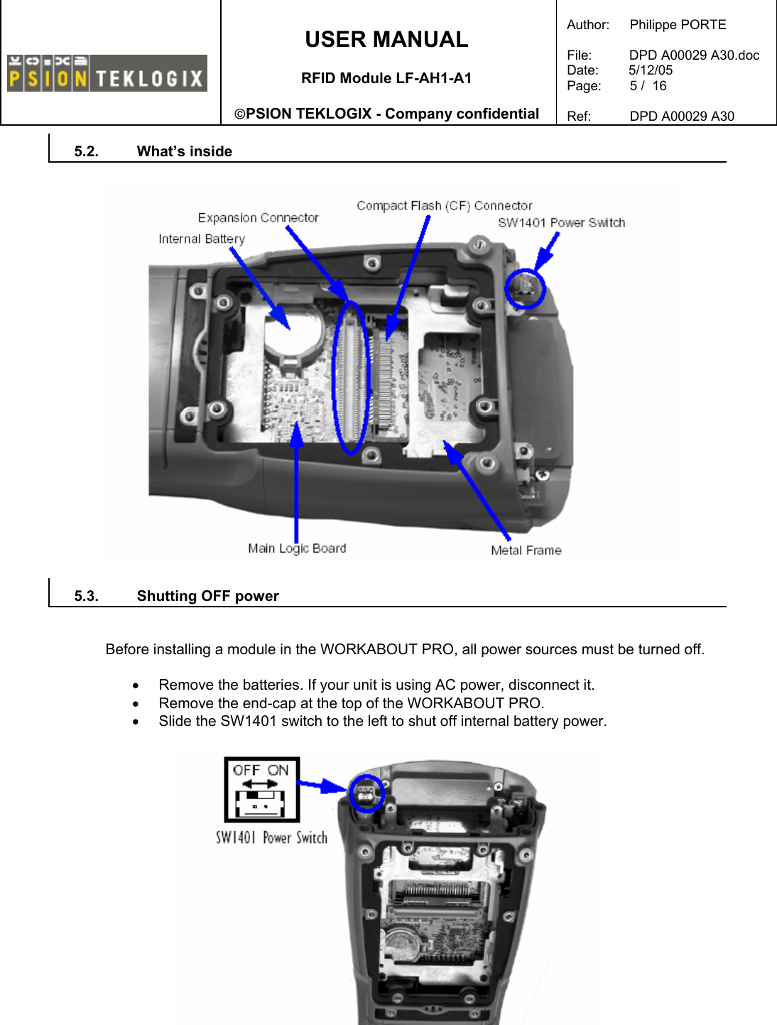
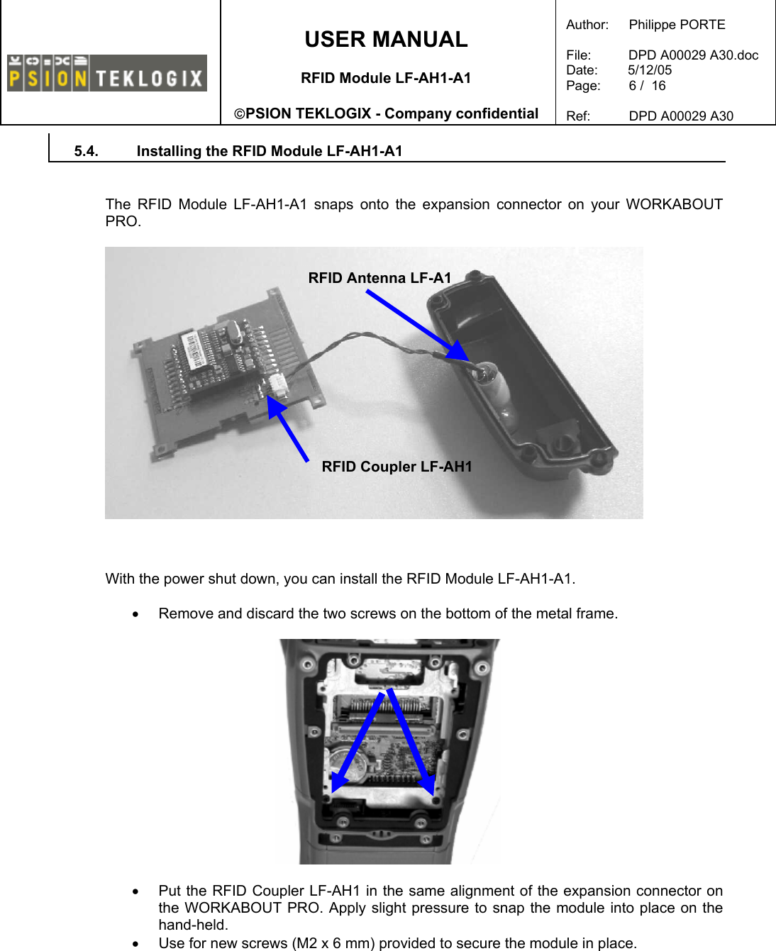
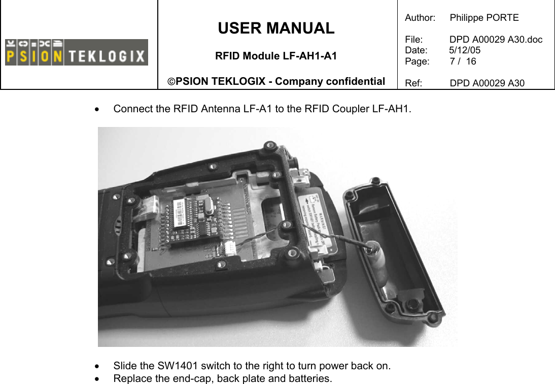
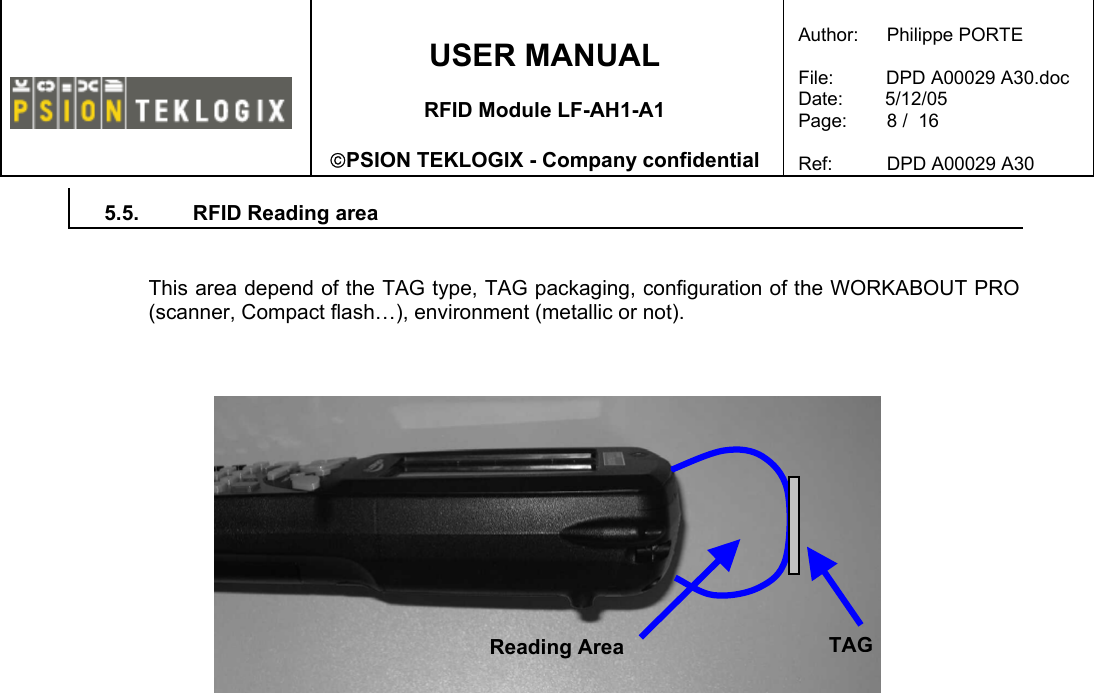
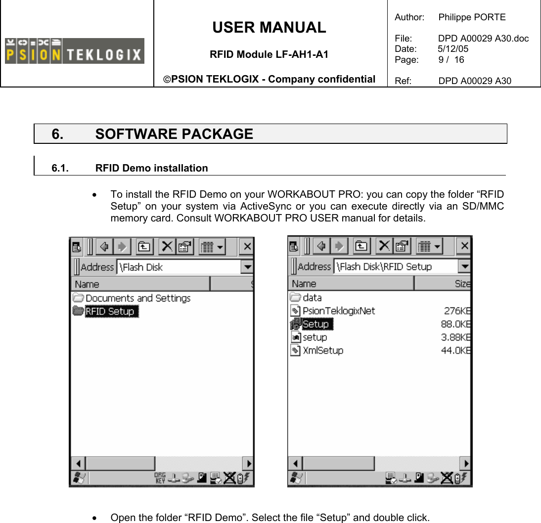
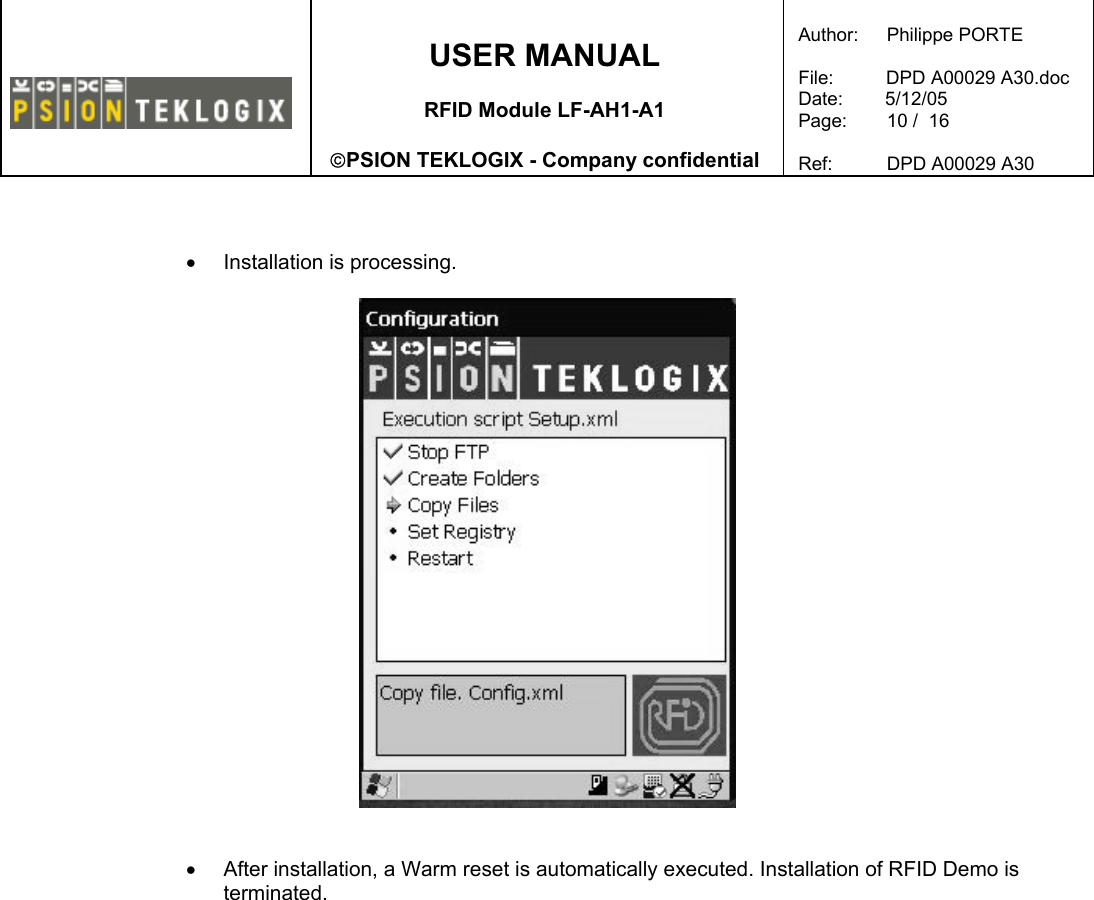
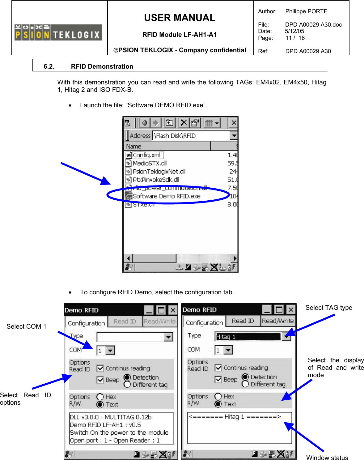
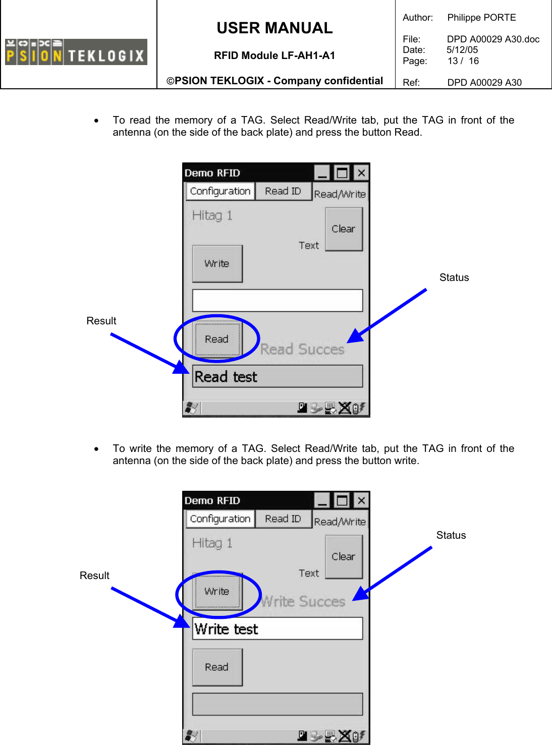
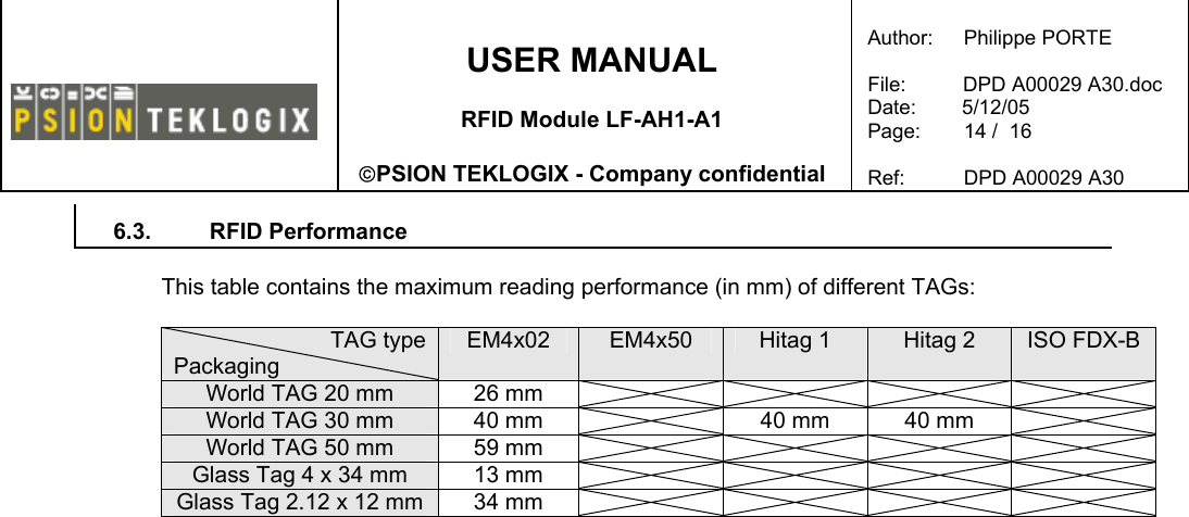
Psion LFAH1 RFID Module LF-AH1-A1 User Manual DPD A00029 A30

Psion Inc RFID Module LF-AH1-A1 DPD A00029 A30

User Manual

   USER MANUAL  RFID Module LF-AH1-A1  PSION TEKLOGIX - Company confidential  Author:   Philippe PORTE  File:          DPD A00029 A30.doc Date:        5/12/05 Page:   1 /  16  Ref:   DPD A00029 A30                 USER MANUAL  RFID Module LF-AH1-A1  Author:   Philippe PORTE File:  DPD A00029 A30.doc Date: 04/05/05 Pages: 16 Reference:  DPD A00029 A30                 Revision  Date  Prepared by  Verify by  Validated by A30 04/05/05  Philippe PORTE  Pierre BONNEFOY     Rob Vandervecht     PSION TEKLOGIX Printing date: 12/05/2005 14:35:00
   USER MANUAL  RFID Module LF-AH1-A1  PSION TEKLOGIX - Company confidential  Author:   Philippe PORTE  File:          DPD A00029 A30.doc Date:        5/12/05 Page:   2 /  16  Ref:   DPD A00029 A30    TABLE OF CONTENTS  1. SCOPE OF DOCUMENT .................................................................................. 3 2. TERMINOLOGY................................................................................................ 3 3. UPDATING OF DOCUMENT ............................................................................ 3 4. ENVIRONMENT ................................................................................................ 3 4.1. DOCUMENTS AND REFERENCE ELEMENTS ..................................................................................... 3 5. RFID MODULE INSTALLATION....................................................................... 4 5.1. REMOVING THE END-CAP AND BACK PLATE.................................................................................. 4 5.2. WHAT’S INSIDE ............................................................................................................................ 5 5.3. SHUTTING OFF POWER ............................................................................................................... 5 5.4. INSTALLING THE RFID MODULE LF-AH1-A1................................................................................. 6 5.5. RFID READING AREA................................................................................................................... 8 6. SOFTWARE PACKAGE ................................................................................... 9 6.1. RFID DEMO INSTALLATION .......................................................................................................... 9 6.2. RFID DEMONSTRATION ............................................................................................................. 11 6.3. RFID PERFORMANCE ................................................................................................................ 14 7. RFID REGULATORY INFORMATION ............................................................ 15
   USER MANUAL  RFID Module LF-AH1-A1  PSION TEKLOGIX - Company confidential  Author:   Philippe PORTE  File:          DPD A00029 A30.doc Date:        5/12/05 Page:   3 /  16  Ref:   DPD A00029 A30    1.  SCOPE OF DOCUMENT  This document describes the method to install the RFID Module LF-AH1-A1 in the Psion Teklogix WORKABOUT PRO and to install the preliminary software package.  2. TERMINOLOGY    3.  UPDATING OF DOCUMENT   Version Evolutions  Author  Date A00 Creation  Philippe PORTE 12/01/05 A10  Up date   Philippe PORTE  09/02/05 A20  Antenna LF-A1, FCC and CE  Philippe PORTE  02/05/05 A30  New demo software  Philippe PORTE  04/05/05 4. ENVIRONMENT   4.1.  Documents and reference elements     Document Reference Version Date
   USER MANUAL  RFID Module LF-AH1-A1  PSION TEKLOGIX - Company confidential  Author:   Philippe PORTE  File:          DPD A00029 A30.doc Date:        5/12/05 Page:   4 /  16  Ref:   DPD A00029 A30    5.  RFID MODULE INSTALLATION   Easily installable expansion modules for the WORKABOUT PRO allow you to customise this hand-held to meet your specific mobile computing requirements. This chapter outlines how to install the RFID Module LF-AH1-A1 (this module is composed of one RFID Coupler LF-AH1 and one RFID Antenna LF-A1).   5.1.  Removing the End-Cap and Back Plate   To install a module, you’ll need to remove the end-cap and back plate on the WORKABOUT PRO. This is a simple process of unfastening four screws on the end-cap and six screws on the back plate.
   USER MANUAL  RFID Module LF-AH1-A1  PSION TEKLOGIX - Company confidential  Author:   Philippe PORTE  File:          DPD A00029 A30.doc Date:        5/12/05 Page:   5 /  16  Ref:   DPD A00029 A30   5.2. What’s inside    5.3.  Shutting OFF power   Before installing a module in the WORKABOUT PRO, all power sources must be turned off.  •  Remove the batteries. If your unit is using AC power, disconnect it. •  Remove the end-cap at the top of the WORKABOUT PRO. •  Slide the SW1401 switch to the left to shut off internal battery power.
   USER MANUAL  RFID Module LF-AH1-A1  PSION TEKLOGIX - Company confidential  Author:   Philippe PORTE  File:          DPD A00029 A30.doc Date:        5/12/05 Page:   6 /  16  Ref:   DPD A00029 A30   5.4.  Installing the RFID Module LF-AH1-A1   The RFID Module LF-AH1-A1 snaps onto the expansion connector on your WORKABOUT PRO.      With the power shut down, you can install the RFID Module LF-AH1-A1.  •  Remove and discard the two screws on the bottom of the metal frame.    •  Put the RFID Coupler LF-AH1 in the same alignment of the expansion connector on the WORKABOUT PRO. Apply slight pressure to snap the module into place on the hand-held. •  Use for new screws (M2 x 6 mm) provided to secure the module in place.  RFID Antenna LF-A1 RFID Coupler LF-AH1
   USER MANUAL  RFID Module LF-AH1-A1  PSION TEKLOGIX - Company confidential  Author:   Philippe PORTE  File:          DPD A00029 A30.doc Date:        5/12/05 Page:   7 /  16  Ref:   DPD A00029 A30   •  Connect the RFID Antenna LF-A1 to the RFID Coupler LF-AH1.    •  Slide the SW1401 switch to the right to turn power back on. •  Replace the end-cap, back plate and batteries.
   USER MANUAL  RFID Module LF-AH1-A1  PSION TEKLOGIX - Company confidential  Author:   Philippe PORTE  File:          DPD A00029 A30.doc Date:        5/12/05 Page:   8 /  16  Ref:   DPD A00029 A30   5.5.  RFID Reading area   This area depend of the TAG type, TAG packaging, configuration of the WORKABOUT PRO (scanner, Compact flash…), environment (metallic or not).       TAGReading Area
   USER MANUAL  RFID Module LF-AH1-A1  PSION TEKLOGIX - Company confidential  Author:   Philippe PORTE  File:          DPD A00029 A30.doc Date:        5/12/05 Page:   9 /  16  Ref:   DPD A00029 A30    6. SOFTWARE PACKAGE  6.1.  RFID Demo installation  •  To install the RFID Demo on your WORKABOUT PRO: you can copy the folder “RFID Setup” on your system via ActiveSync or you can execute directly via an SD/MMC memory card. Consult WORKABOUT PRO USER manual for details.       •  Open the folder “RFID Demo”. Select the file “Setup” and double click.
   USER MANUAL  RFID Module LF-AH1-A1  PSION TEKLOGIX - Company confidential  Author:   Philippe PORTE  File:          DPD A00029 A30.doc Date:        5/12/05 Page:   10 /  16  Ref:   DPD A00029 A30     •  Installation is processing.     •  After installation, a Warm reset is automatically executed. Installation of RFID Demo is terminated.
   USER MANUAL  RFID Module LF-AH1-A1  PSION TEKLOGIX - Company confidential  Author:   Philippe PORTE  File:          DPD A00029 A30.doc Date:        5/12/05 Page:   11 /  16  Ref:   DPD A00029 A30   6.2. RFID Demonstration  With this demonstration you can read and write the following TAGs: EM4x02, EM4x50, Hitag  1, Hitag 2 and ISO FDX-B.  •  Launch the file: “Software DEMO RFID.exe”.     •  To configure RFID Demo, select the configuration tab.         Window status Select COM 1 Select Read ID options Select the display of Read and write mode Select TAG type
   USER MANUAL  RFID Module LF-AH1-A1  PSION TEKLOGIX - Company confidential  Author:   Philippe PORTE  File:          DPD A00029 A30.doc Date:        5/12/05 Page:   12 /  16  Ref:   DPD A00029 A30    •  To read the ID of TAG, select Read tab and press the button Read. Put the TAG in front of the antenna (on the side of the back plate).      Serial number of TAG  Sum of reading TAG Sum of different TAGs  Sum of different reading TAGs
   USER MANUAL  RFID Module LF-AH1-A1  PSION TEKLOGIX - Company confidential  Author:   Philippe PORTE  File:          DPD A00029 A30.doc Date:        5/12/05 Page:   13 /  16  Ref:   DPD A00029 A30    •  To read the memory of a TAG. Select Read/Write tab, put the TAG in front of the antenna (on the side of the back plate) and press the button Read.      •  To write the memory of a TAG. Select Read/Write tab, put the TAG in front of the antenna (on the side of the back plate) and press the button write.    Status Result Status Result
   USER MANUAL  RFID Module LF-AH1-A1  PSION TEKLOGIX - Company confidential  Author:   Philippe PORTE  File:          DPD A00029 A30.doc Date:        5/12/05 Page:   14 /  16  Ref:   DPD A00029 A30   6.3. RFID Performance  This table contains the maximum reading performance (in mm) of different TAGs:  TAG type Packaging EM4x02  EM4x50  Hitag 1  Hitag 2  ISO FDX-B World TAG 20 mm  26 mm         World TAG 30 mm  40 mm    40 mm  40 mm   World TAG 50 mm  59 mm         Glass Tag 4 x 34 mm  13 mm         Glass Tag 2.12 x 12 mm  34 mm
   USER MANUAL  RFID Module LF-AH1-A1  PSION TEKLOGIX - Company confidential  Author:   Philippe PORTE  File:          DPD A00029 A30.doc Date:        5/12/05 Page:   15 /  16  Ref:   DPD A00029 A30    7.  RFID REGULATORY INFORMATION
   USER MANUAL  RFID Module LF-AH1-A1  PSION TEKLOGIX - Company confidential  Author:   Philippe PORTE  File:          DPD A00029 A30.doc Date:        5/12/05 Page:   16 /  16  Ref:   DPD A00029 A30   IMPORTANT NOTE FOR NORTH AMERICA:  The RFID must not be used whilst the host WORKABOUT PRO is being powered by the ac/dc adaptor.  FCC Information to Users:  This product and it antennas must not be co-located or operated in conjunction with any other antenna or transmitter.  Radiation Exposure Compliance This product complies with the FCC RF exposure limits for an uncontrolled environment. For continued compliance, the product must not be held closer than 20 cm from the rest of the body.  Federal Communication Commission Interference Statement.  This equipment has been tested and found to comply with the limits for a Class B digital device, pursuant to Part 15 of the FCC Rules. These limits are designed to provide reasonable protection against harmful interference in a residential installation. This equipment generates, uses and can radiate radio frequency energy and, if not installed and used in accordance with the instructions, may cause harmful interference to radio communications. However, there is no guarantee that interference will not occur in a particular installation.  If this equipment does cause harmful interference to radio or television reception, which can be determined by turning the equipment off and on, the user is encouraged to try to correct the interference by one of the following measures:   •   Reorient or relocate the receiving antenna. •   Increase the separation between the equipment and receiver. •   Connect the equipment into an outlet on a circuit different from that to which the receiver is connected. •   Consult the dealer or an experienced radio/TV technician for help.   This device complies with Part 15 of the FCC Rules. Operation is subject to the following two conditions: (1) This device may not cause harmful interference, and (2) this device must accept any interference received, including interference that may cause undesired operation.   FCC Caution: Any changes or modifications not expressly approved by the party responsible for compliance could void the user's authority to operate this equipment.   Emissions Information for Canada:  This Class B digital apparatus complies with Canadian ICES-003. Cet appareil numérique de la classe B est conforme à la norme NMB-003 du Canada.

Navigation menu