Psion RA2040 Psion Teklogix 'g' Radio User Manual Wireless CF Card Quick Installation Guide
Psion Inc Psion Teklogix 'g' Radio Wireless CF Card Quick Installation Guide
Psion >
users manual

Psion Teklogix RA2040
802.11 b/g Wireless CF Card
User Manual
1

Contents
1.0 Introduction
2.0 Install and Configure a Wireless Network
3.0 Specifications
4.0 Basic Troubleshooting
2
1.0 Introduction
The Psion Teklogix RA2040 is a Compact Flash 802.11 b/g radio. The small CF form factor allows the card to be
used in mobile computing devices such as a PDA. The card is WiFi certified hence able to
communicate with other vendor’s WiFi APs. In addition it supports a foray of security features and
CCXv3 for compatibility with Cisco certified APs.
Features
CF Type II extended
Available in 2 versions: internal antenna and external antenna
Hardware
-20°C to +70°C
802.11 b/g complaint, WiFi certified
+13dBm ±1.5dBm power output
Antenna diversity is not supported
RF
Marvell 88W8385 MAC and 88W8015 Transceiver chipset
Driver: WinCE4.2, WinCE5.0, Windows Pocket PC2003, Window Mobile Edition,
Linux 2.4.22 and above
Software
Security: WEP, TKIP, WPA, WPAII, AES-CCMP, CCX v1-3
2.0 Install and Configure a Wireless Network
Follow these steps to install the Marvell WinCE driver.
3
S
St
te
ep
p
1
1:
:
I
In
ns
st
ta
al
ll
li
in
ng
g
M
Mi
ic
cr
ro
os
so
of
ft
t
A
Ac
ct
ti
iv
ve
eS
Sy
yn
nc
ch
h
o
on
n
a
a
h
ho
os
st
t
c
co
om
mp
pu
ut
te
er
r.
.
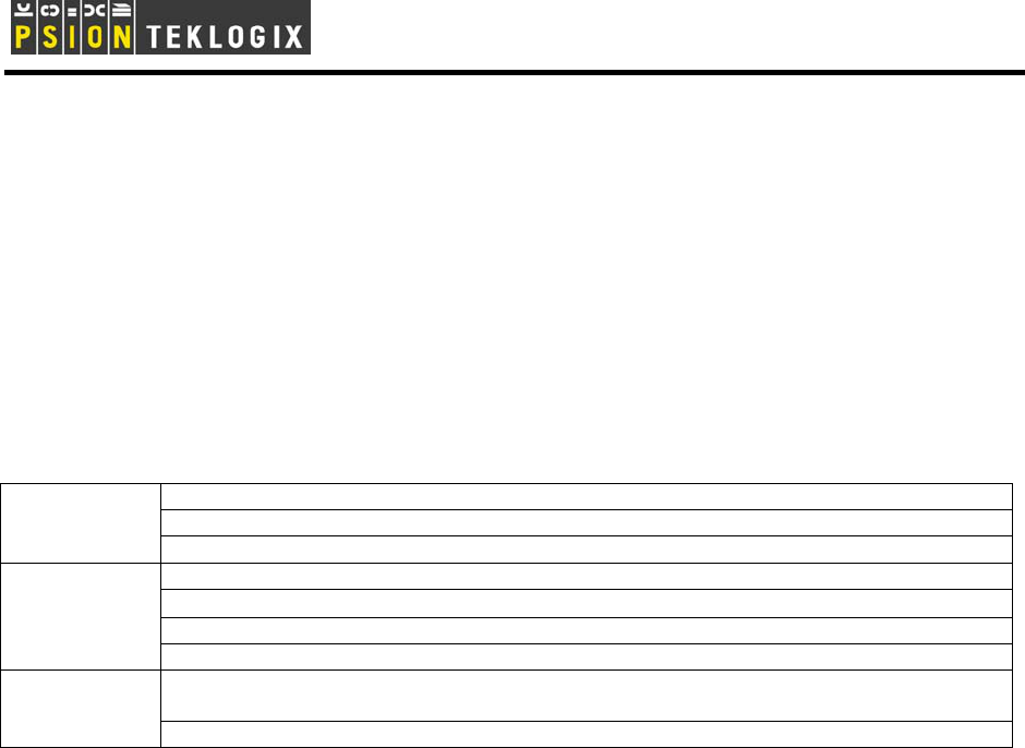
- Please download MiS
ActiveSynch® 3.0 or higher and
install on your host computer.
- Make sure the “Allow USB
connection with this desktop
computer” button is checked.
This can be viewed under “File”
then “Connection Settings…”
- Use a USB cable to connect
the mobile device to the PC.
S
St
te
ep
p
2
2:
:
S
Se
et
tt
ti
in
ng
g
u
up
p
t
th
he
e
m
mo
ob
bi
il
le
e
d
de
ev
vi
ic
ce
e
f
fo
or
r
A
Ac
ct
ti
iv
ve
eS
Sy
yn
nc
c.
.
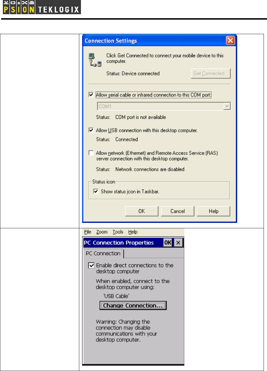
- The mobile device should
have linked with the desktop
computer once the USB cable
is connected. If not then follow
these steps.
- Open “Control Panel” and
double click on “PC Connection”
icon.
- Make sure the “Enable direct
connections to the desktop
computer” is checked.
4
S
St
te
ep
p
3
3:
:
D
Do
ow
wn
nl
lo
oa
ad
di
in
ng
g
d
dr
ri
iv
ve
er
r
t
to
o
m
mo
ob
bi
il
le
e
d
de
ev
vi
ic
ce
e.
.
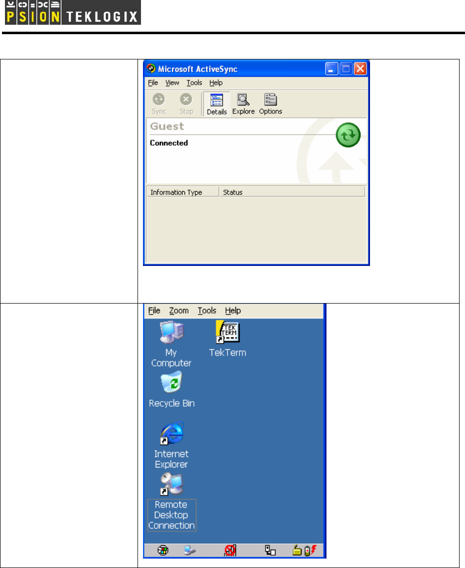
- Once ActiveSync recognizes a
device it will ask if you want to
set up a new partnership.
Select “No” and click “Next” to
see the root screen.
- Click “Explore” then “Flash
Disk” to see the content of the
non-volatile storage area.
- Download the driver CAB file
to this Flash Disk directory.
- Change the property of the
driver CAB file to “Read-only”.
- Double click on the driver CAB
file to install the Marvell driver it
in its default location.
S
St
te
ep
p
4
4:
:
D
Di
is
sc
co
on
nn
ne
ec
ct
t
t
th
he
e
m
mo
ob
bi
il
le
e
d
de
ev
vi
ic
ce
e
a
an
nd
d
r
re
es
st
ta
ar
rt
t
- Remove the USB cable
- Turn off mobile device.
- Insert the radio if not already
done so.
- Turn on mobile device. You
should see the generic WLAN
icon (5 unfilled bars) with the
red circle and slash indicating
the radio driver has loaded but
the radio is not associated to
any AP.
5
S
St
te
ep
p
5
5:
:
S
Se
et
tt
ti
in
ng
g
u
up
p
t
th
he
e
m
mo
ob
bi
il
le
e
d
de
ev
vi
ic
ce
e
t
to
o
c
co
on
nn
ne
ec
ct
t
t
to
o
a
a
w
wi
ir
re
el
le
es
ss
s
L
LA
AN
N
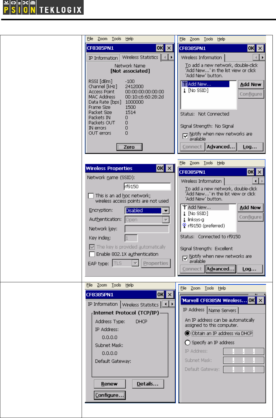
- Double click on the WLAN
signal quality icon.
- Click on the right arrow button
to see the “Wireless
Information” tab.
- Click “Add New”.
- Enter the SSID name of the
AP. The example shows an
unsecured connection to an AP
with SSID “rf9150”. Click OK
to save the settings.
- The mobile device should now
be associated with the desired
SSID.
S
St
te
ep
p
6
6:
:
S
Se
et
tt
ti
in
ng
g
u
up
p
t
th
he
e
m
mo
ob
bi
il
le
e
d
de
ev
vi
ic
ce
e
t
to
o
c
co
on
nn
ne
ec
ct
t
t
to
o
a
a
n
ne
et
tw
wo
or
rk
k
- Click on the left arrow key to
see the “IP Information” tab.
- Click “Configure” to see the IP
“Address” window.
- In most situation “Obtain an IP
address via DHCP” will be
checked. Click “OK” to close.
- If no DHCP server is available
then manually assign an IP
address and subnet mask.
6
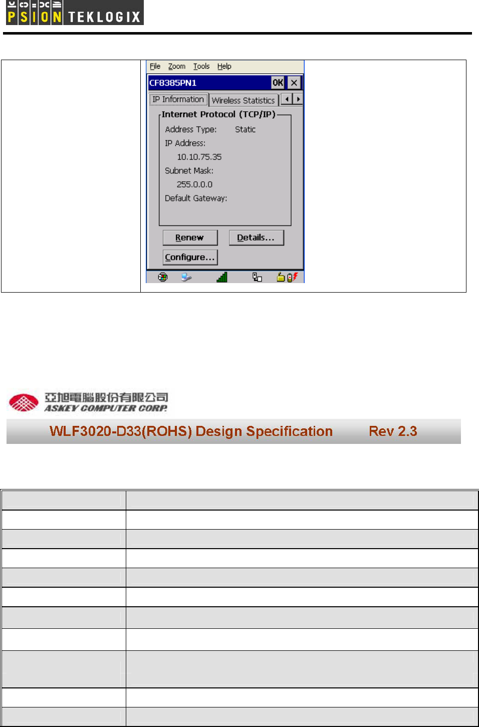
- If all goes well, you should see
that the radio has taken an IP
address and the signal quality
icon no longer shows the red
circle.
.
3.0 Specification
Hardware
Host Interfaces Compact Flash
Compatible Interfaces Compact Flash TypeΙI
Form factor Compact Flash TypeΙI
Chipset MARVELL 88W8385 + 88W8015
Operation Voltage DC 3.3V
Network Standards IEEE 802.11g/b
Modulation Techniques DBPSK, DQPSK, CCK, 16QAM, 64QAM,
Modulation Technology DSSS and OFDM
Data Rate
802.11b: 11, 5.5, 2, 1 Mbps
802.11g: 54, 48, 36, 24, 18, 12, 9, 6 Mbps
Network Architectures Infrastructure and Ad Hoc
Operating Frequencies 2.4 – 2.5 GHz
7
Operating Channels 802.11b/g: 1-11 for North America
Before antenna
RF Output Power 802.11b (1M,2M,5.5M,11M) : 15 dBm + - 1.5dBm
802.11g (6M,9M,12M,18M,24M,36M, 48M,54M) : 13 dBm + - 1.5dBm
802.11b:1M=-89dBm,2M=-89dBm,5.5M=-89dBm,11M=-87dBm
Receiver sensitivity 802-11g:6M=-83dBm,9M=-83dBm,12M=-83dBm,18M=-83dBm,24M=-81dBm
36M=-78dBm,48M=-74dBm,54M=-72dBm
Power Consumption Tx peak: 490mA @ 3.3VDC; Rx peak: 260mA @ 3.3VDC
Support Voltage 3.3V
Security WEP 64-and 128-bit encryption with hardware TKIP processing.
WPA.
AES-CCMP hardware implementation as part of 802.11i security
standard
Delay Tolerance Multipath R.M.S Delay Spread @ 10%FER 680 ns in 11M mode,150ns in
54M mode
Software Support Windows CE 4.2 & 5.0,.Linux
Temperatures Operates from -20 to 70 ℃ Storage from -40 to 120 ℃
Humidity
(non-condensing) 5 to 95%
Certifications
Wi-Fi Pretest*; FCC part 15C/15.247*; ETS 300 328-2*; UL*; IEC60950*; EN
301 489-1,17*; prEN50371*;CE Mark*; TELEC*
Marvell WLAN 802.11b/g CF8385PN Software Feature
Short preamble
802.11b, 802.11g, and g/b mix-mode infrastructure
802.11b and 802.11g Adhoc mode
Transmit fragmentation and receive defragmentation
Client IEEE Power Save Infrastructure & Adhoc mode
Basic rate adaptation - 11g/b for optimizing each STA throughput
Core Features
Background scan
64/ 128-bit WEP Encryption and open/ shared authentication
WPA PSK
WPA 802.1x
Security
WPAII PSK**
8
WPAII 802.1x**
Cisco LEAP & PEAP
Cisco CCX V1 (LEAP)
Cisco CCX V2 (PEAP)
Cisco CCX V3 (EAP- Fast)**
Hardeare AES
802.11i**
AH Security**
IEEE 802.11b
IEEE 802.11g
IEEE 802.11d**
IEEE 802.11e (EDCA)**
IEEE 802.11e (HCCA)**
IEEE Standards
IEEE 802.11h (DFS and TPC)**
Wi-Fi WME**
Other Standards
Wi-Fi WSM APSD**
Drivers for the following
Operating Systems
Windows CE.net (CE4.2, CE5.0) Windows Pocket PC 2003 Windows
Mobile Edition Linux 2.4.22 and above
Network Protocol TCP/IP, IPX
** Support in the future
Warning: To satisfy FCC RF exposure requirements for mobile transmitting devices, a separation
distance of 20cm or more should be maintained between the antenna of this device and persons during
device operation. To ensure compliance, operation at closer than this distance is not recommended.
FCC Part 15 Statement
This device complies with Part 15 of the FCC Rules. Operation subject to the following conditions:
(1) This device may not cause harmful interference.
(2) This device must accept any interference received, including interference that may cause
undesired operation.
.
9
This transmitter must not be co-located or operating in conjunction with any other antenna or
transmitter.
This product has to use MOBILEMARK antenna model IMAG5-2400.
4.0 Basic Troubleshooting
Symptom Cause Remedy
“Wireless card not recognized”
message during start up
Unknown Re-install driver
Wireless network detected but
unable to connect
Security settings are not valid Configure security feature
10
Labelling: When the radio module is assembled inside a host and is not visible from outside then the host equipment
has to be labelled as follows:
This product contains:
Psion Teklogix Model: RA2040
FCC ID: GM3RA2040
IC: 2739D-RA2040
WARNING: Changes or modifications not expressly approved by Psion Teklogix Inc. could void the user's authority to operate the equipment.
NOTE: This equipment has been tested and found to comply with the limits for a class B digital device, pursuant to part 15 of the FCC
Rules. These limits are designed to provide reasonable protection against harmful interference in a residential installation.
This equipment generates, uses, and can radiate radio frequency energy and, if not installed and used in accordance with the instructions,
may cause harmful interference to radio communications. However, there is no guarantee that interference will not occur in a particular
installation. If this equipment does cause harmful interference to radio or television, which can be determined by turning the equipment off
and on, the user is encouraged to try to correct the interference by one or more of the following measures:
-Reorient or relocate the receiving antenna.
-Increase the separation between the equipment and receiver.
-Connect the equipment into an outlet on a circuit different from that to which the receiver is connected.
-Consult the dealer or an experienced radio/TV technician for help.