Psion UHFCA3AC5GPRS RFID MODULE UHF-CA3-AC5-GPRS User Manual
Psion Inc RFID MODULE UHF-CA3-AC5-GPRS Users Manual
Psion >
Users Manual
WORKABOUT PRO G2 RFID MODULE UHF-CA3-AC5-GPRS
EXPANSION MODULE INSTRUCTIONS
Important: All Approval and safety information is outlined in the ‘Workabout pro G2 Handheld-computer
User Manual’ – part number 8100140A. This manual is available on our website www.psionteklogix.com
through the Psion Teklogix community website.
Easily installable expansion modules for the WORKABOUT PRO allow you to customise this hand-held to
meet your specific mobile computing requirements. This chapter outlines how to install the RFID Module
UHF-CA3-AC5-GPRS.
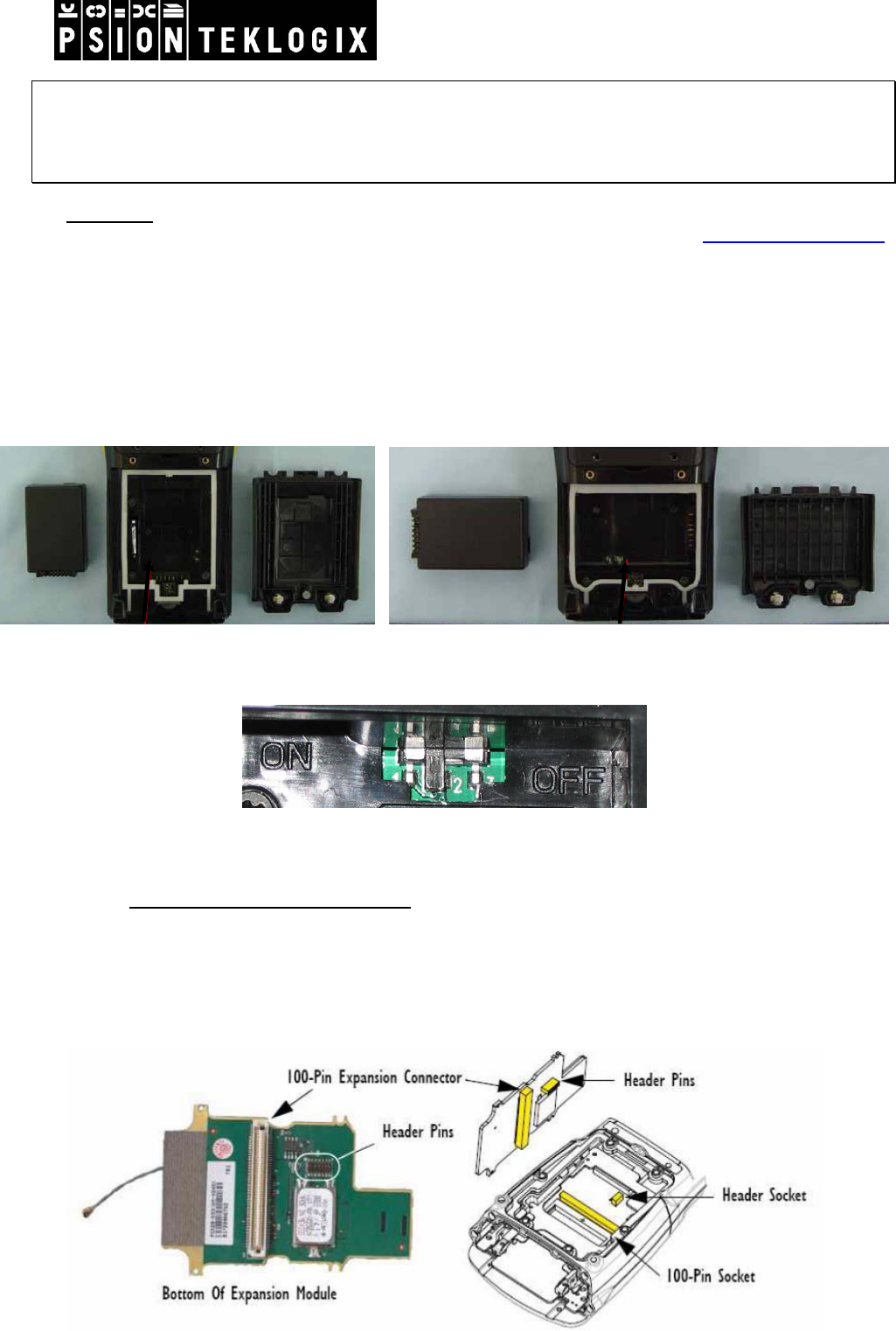
Before installing a module in the WORKABOUT PRO G2, all power sources must be turned off.
• Remove the batteries. If your unit is using AC power, disconnect it.
WAP C G2 WAP S G2
• Slide the switch to position OFF to shut off internal battery power.
With the power shut down, you can install the RFID Module UHF-CA3-AC5-GPRS.
• Installing the GPRS Radio Module
The GSM/GPRS (model RA3030-G2) radio module includes a radio and an antenna, and includes a SIM
card holder. The SIM card, required to use the radio, is sold separately.
This radio module requires an end-cap with a protrusion to accommodate the antenna.
The GSM/GPRS expansion module aligns with mating connectors in the WORKABOUT PRO:
April 07, 2010
DPD A00515 A00 Sheet 1 of 12
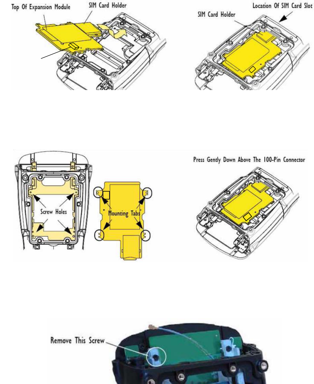
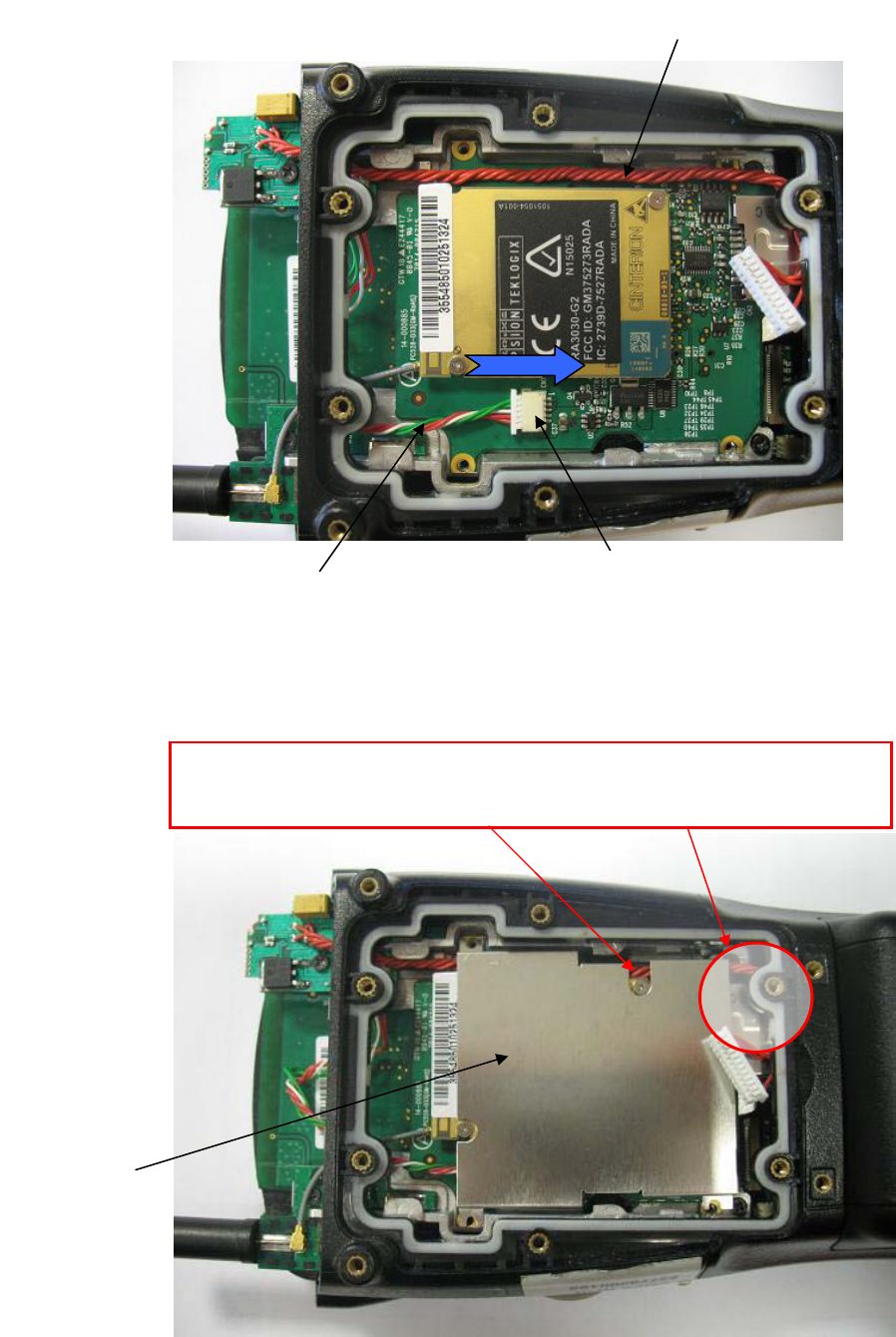
1. Slide the SIM Card holder under the edge of the WORKABOUT PRO case until it meets the
inside of the SIM Card slot :
Power connector
2. Align the 100-pin expansion connector and the header pins on the expansion module with the
expansion connector and the header connector on the main logic board of the WORKABOUT
PRO.
3. Align the four mounting tabs on the expansion module with the four screw holes in the internal
frame inside the WORKABOUT PRO :
4. Apply slight pressure above the 100-pin connector to snap the module into place.
5. Remove the scanner flex cable from the WORKABOUT PRO.
6. Tuck the antenna cable through the frame.
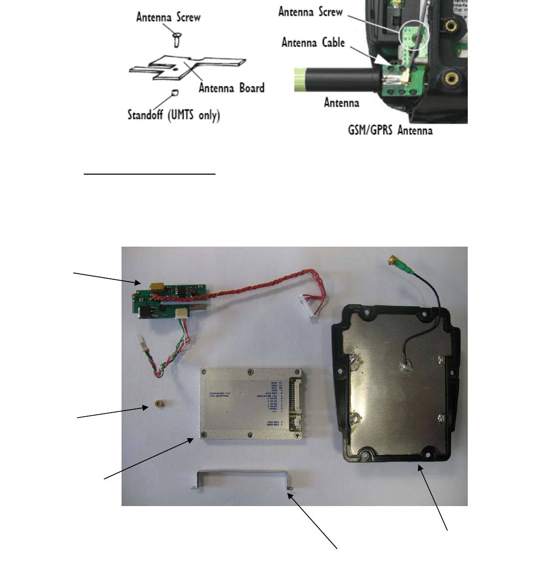
7. Remove the antenna screw indicated in the Figure below before inserting the GPRS antenna.
April 07, 2010
DPD A00515 A00 Sheet 2 of 12
8. Set the antenna into place. The antenna slides in along the frame.
9. Use the long screw provided to fasten the antenna to the frame
10. Snap the antenna cable onto the antenna
• Installing the RFID Module:
The RFID Module includes a RFID module UHF-CA3-GPRS (an electronic interface board + RFID
Coupler) and RFID circular antenna UHF-AC5.
RFID Circular Antenna
Stopper
Electronic
Interface
Board
Standoff
RFID Coupler
April 07, 2010
DPD A00515 A00 Sheet 3 of 12
1. Remove the screw indicated in the Figure below before inserting the electronic interface
board.
Remove this screw
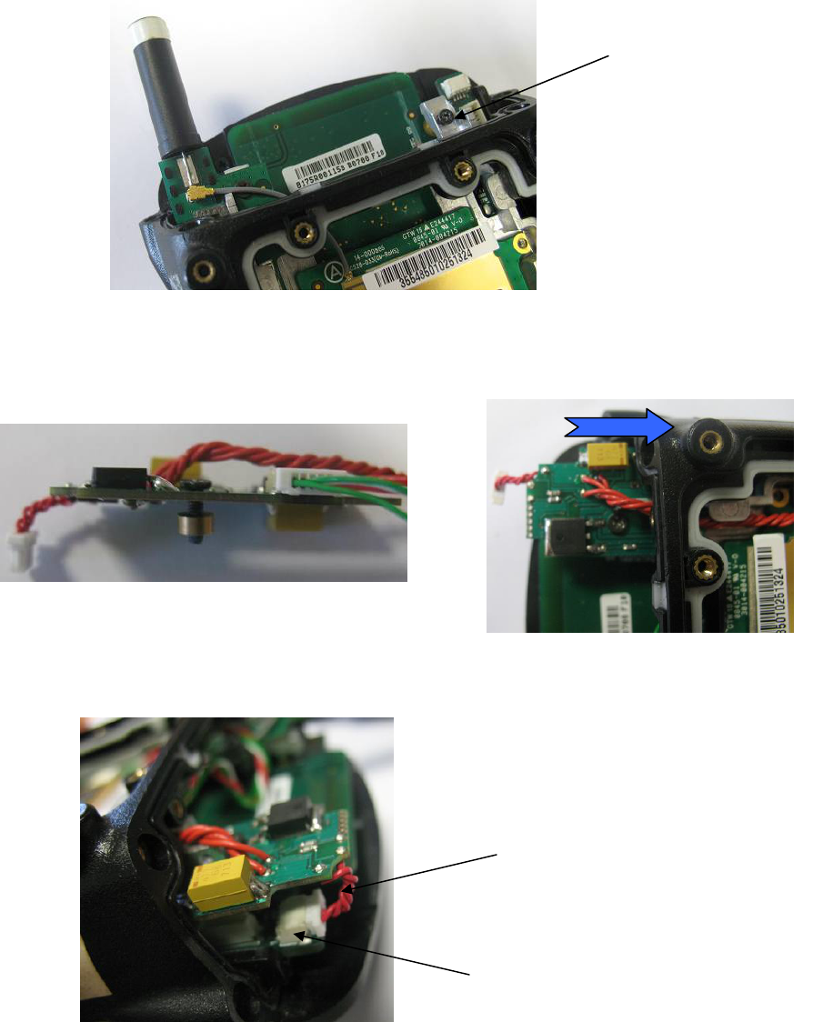
2. Set the interface board into place. The interface board slides in along the frame.
3. Use the long screw and the standoff provided to fasten the interface board to the frame.
April 07, 2010
DPD A00515 A00 Sheet 4 of 12
4. Connect the USB cable of the Interface board on the USB connector of the WAP.
USB Connector
USB Cable
5. Connect the power supply cable of the Interface board on the Power connector of the GPRS
Radio module. Then, align the serial cable like in the picture below.
April 07, 2010
DPD A00515 A00 Sheet 5 of 12
6. Settle the metal shield into place on top of the GSM/GPRS expansion module. It aligns to the
same screw holes as the expansion module.
Serial cable
Power connector
Power supply cable
Metal shield
Be careful to well align the serial cable and not to pinch the serial cable
with the metal shield. And put the end of the serial cable under the
plastic.
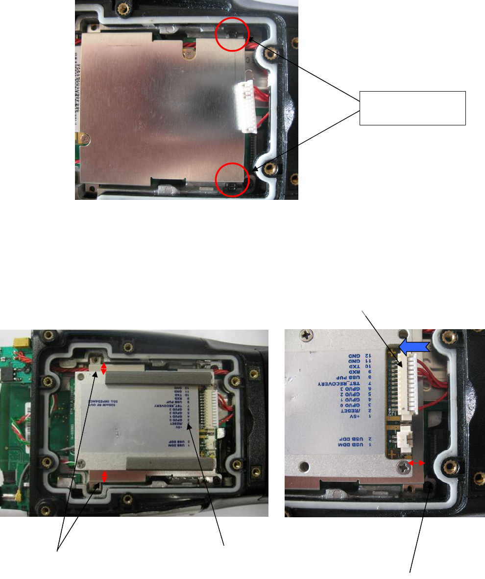
7. In a first time use only two screws (M2 x 6 mm) provided to secure the metal shield in place.
Put only these two
screws at this stage
8. Fix the RFID Coupler into place on the top of the metal shield. The RFID coupler has to be
aligned at the centre of the WORKABOUT PRO and respect the following distance from the
metal shield :
9. Snap the serial connector into the RFID coupler connector :
RFID Coupler
5 mm 3 mm
RFID coupler connector
April 07, 2010
DPD A00515 A00 Sheet 6 of 12
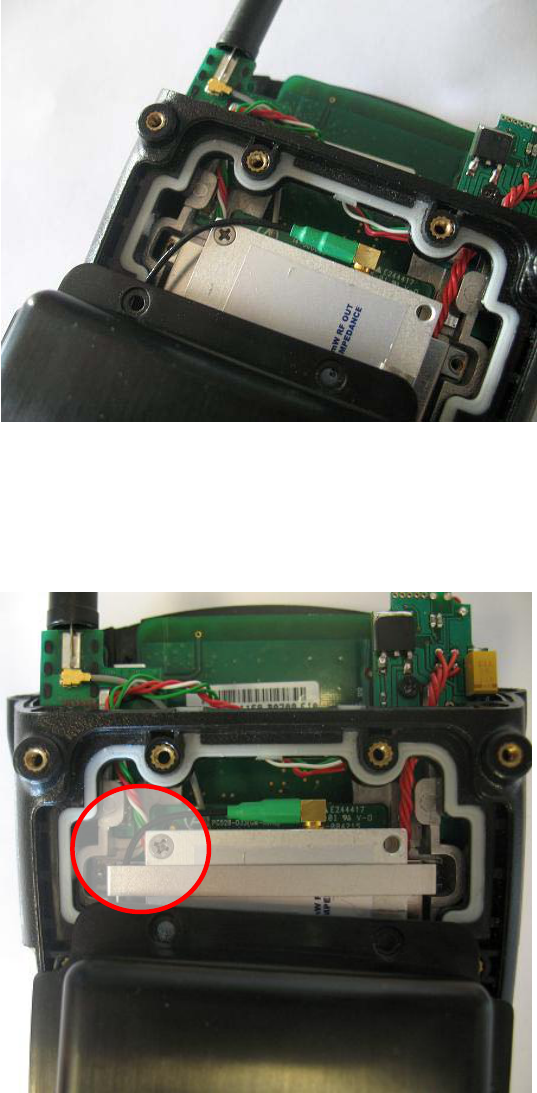
10. Connect the RFID Antenna UHF-AC5 to the RFID Coupler.
11. Put the “stopper” and use the two last screws (M2 x 6 mm) provided to secure the module in
place. Be careful to the routing of the cable (see the picture below).
April 07, 2010
DPD A00515 A00 Sheet 7 of 12
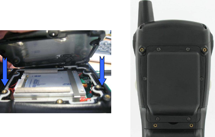
12. Close the extended back plate with the RFID antenna and replace the end-cap.
April 07, 2010
DPD A00515 A00 Sheet 8 of 12
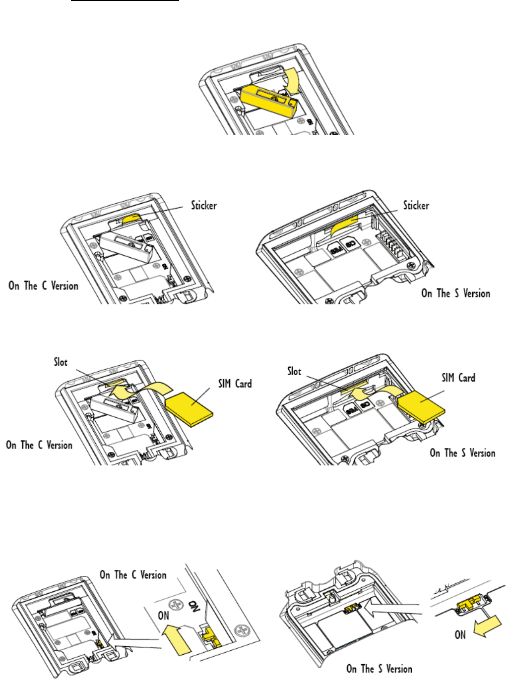
• Inserting The SIM Card
1. On the C version of the WORKABOUT PRO, open the card gate in the battery compartment:
2. Remove the sticker covering the SIM Card slot:
3. Slide the SIM Card into the upper slot in the battery compartment:
The card should be oriented with the contacts down and the notch to the front and left, according to
the diagram in the battery compartment.
4. On the C version of the WORKABOUT PRO, close the card gate.
April 07, 2010
DPD A00515 A00 Sheet 9 of 12
• Slide the hardware power switch to turn battery-backup power back on.
• Replace the battery and battery cover.
For detailed instructions, pleased refer to the WORKABOUT PRO G2 Hand-Held Computer User Manual
and to the RFID MODULE UHF-CA3-AC5-GPRS User manual. These manuals are available on our
website www.psionteklogix.com through the PSION TEKLOGIX community website.
Important: The WORKABOUT PRO G2 with the RFID option must not be held closer than 20 cm
from the rest of the body. This product must not be used in a holster or on a belt-clip.
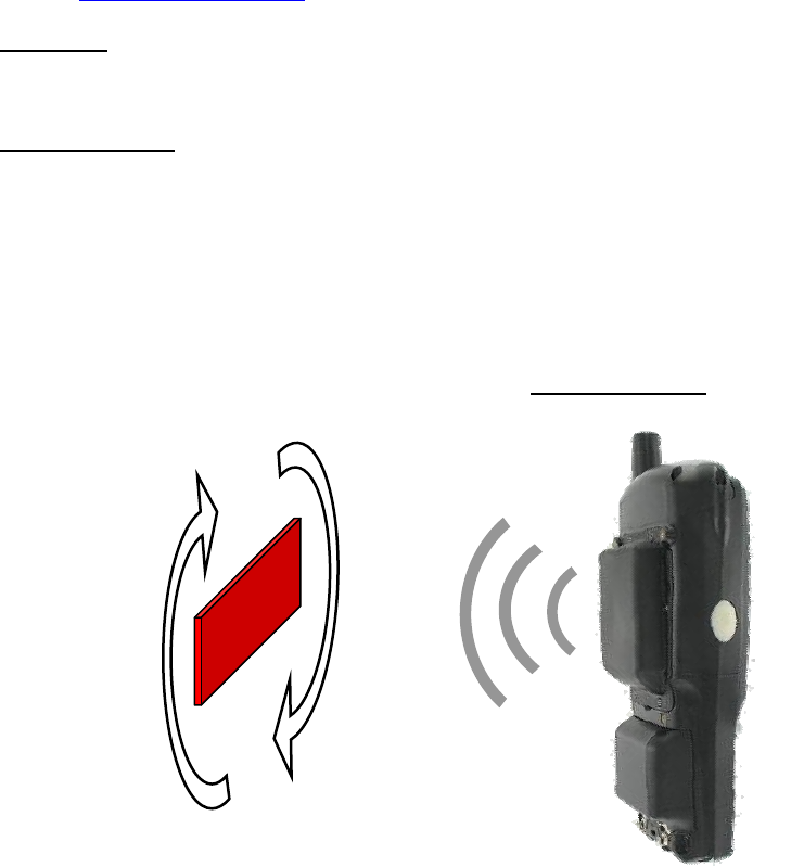
READING AREA:
This area depends on the TAG type, TAG packaging, configuration of the WORKABOUT PRO G2
(scanner, Compact flash…), environment (metallic or not).
April 07, 2010
DPD A00515 A00 Sheet 10 of 12
Circular Antenna
Tag

WORKABOUT PRO G2 RFID MODULE UHF-CA3-AC5-GPRS
RFID Regulatory Information
IMPORTANT NOTE FOR NORTH AMERICA:
The RFID must not be used whilst the host WORKABOUT PRO G2 is being powered by the ac/dc adaptor.
FCC Information to Users:
This product and it antennas must not be co-located or operated in conjunction with any other antenna or
transmitter.
Radiation Exposure Compliance
This product complies with the FCC RF exposure limits for an uncontrolled environment. For continued
compliance, the product must not be held closer than 20 cm from the rest of the body. This product must
not be used in a holster or on a belt-clip.
Federal Communication Commission Interference Statement.
This equipment has been tested and found to comply with the limits for a Class B digital device, pursuant to Part
15 of the FCC Rules.
These limits are designed to provide reasonable protection against harmful interference in a residential
installation. This equipment generates uses and can radiate radio frequency energy and, if not installed and used
in accordance with the instructions, may cause harmful interference to radio communications. However, there is
no guarantee that interference will not occur in a particular installation.
If this equipment does cause harmful interference to radio or television reception, which can be determined by
turning the equipment off and on, the user is encouraged to try to correct the interference by one of the following
measures:
• Reorient or relocate the receiving antenna.
• Increase the separation between the equipment and receiver.
• Connect the equipment into an outlet on a circuit different from that to which the receiver is
connected.
• Consult the dealer or an experienced radio/TV technician for help.
This device complies with Part 15 of the FCC Rules. Operation is subject to the following two conditions: (1) This
device may not cause harmful interference, and (2) this device must accept any interference received, including
interference that may cause undesired operation.
FCC Caution: Any changes or modifications not expressly approved by the party responsible for compliance
could void the user's authority to operate this equipment.
Emissions Information for Canada:
This Class B digital apparatus complies with Canadian ICES-003.
Cet appareil numérique de la classe B est conforme à la norme NMB-003 du Canada.
April 07, 2010
DPD A00515 A00 Sheet 11 of 12