Psion WAOEM187 OEM187 - Workabout RFID User Manual mx manual V 2 0
Psion Inc OEM187 - Workabout RFID mx manual V 2 0
Psion >
users manual

Workabout MX
Service Manual
Psion part no: A6124-0002-02
Version 2.0 - 2000
English

Confidential - PSION ENTERPRISE COMPUTING LTD
Workabout MX Service Manual
Version 2.0 iii
© Copyright Enterprise Computing Ltd 2000.
All rights reserved. This manual and the programs referred to herein are copyrighted works of
Psion Enterprise Computing Ltd, 92 Milton Park, Abingdon, OX14 4RY, United Kingdom.
Reproduction in whole or in part, including utilisation in machines capable of reproduction or
retrieval, without the express written permission of Psion Enterprise Computing Ltd is prohibited.
Reverse engineering is also prohibited.
The information in this document is subject to change without notice.
Psion and the Psion logo are registered trademarks, and Psion Workabout, MX, 3Link, SSD and
Solid State Disk are trademarks of Psion PLC.
Some names referred to are registered trademarks.
Psion Enterprise reserves the right to change the designs and specifications of its products at
any time without prior notice.
Psion part no: A6124-0002-02
Version 2.0 - May 2000
English

Confidential – Enterprise Computing Ltd
Workabout MX Service Manual
Version 2.0 iv
Note
The Psion Workabout contains CMOS devices that may be damaged by electrostatic
discharge (ESD). The following steps to minimise ESD must be taken before the unit is
dismantled. To prevent any damage that could result if the unit or its parts are not handled
properly, observe the following precautions during any handling procedures:
n Minimise all handling of static-sensitive components and assemblies.
n Transport and store static-sensitive components and assemblies in their original containers
or in anti-static bags.
n Label accordingly any package that contains static-sensitive components or assemblies.
n Discharge static electricity from the body by wearing a grounded anti-static wrist strap
while handling these components. Servicing static-sensitive components or assemblies
should be done only at a static-free workstation by qualified service technicians. Increasing
the humidity in the work area minimises static electricity problems.
n Do not allow anything that can generate or hold a static charge on the workstation surface.
n Pick up components by their bodies, never by their leads.
n Do not slide components over any surface.
n Avoid handling components in areas with a floor or work-surface covering that can generate
static charge.
FCC Information for the USA
Radio and Television Interference:
This equipment radiates radio frequency energy and if not used properly - that is, in strict accordance
with the instructions in this manual - may cause interference to Radio and Television reception.
It has been tested and found to comply with the limits for a Class B computing device pursuant to part
15 of the FCC Rules. These are designed to provide reasonable protection against harmful
interference in a residential installation. This equipment can radiate radio frequency energy and, if not
installed and used in accordance with the instructions, may cause harmful interference to radio
communications. However, there is no guarantee that interference will not occur in a particular
installation. If this equipment does cause harmful interference to radio or television reception, which
can be determined by turning the equipment off and on, the user is encouraged to try to correct the
interference by one or more of the following measures:
n Reorient or relocate the receiving antenna.
n Increase the separation distance between the equipment and the receiver.
n If you are using the Workabout computer with a mains adapter, plug it into an outlet, which is on a
different circuit from that to which the receiver is connected.
Consult an authorised Psion dealer or an experienced radio/TV technician for help.
This equipment was tested for FCC compliance under conditions that included the use of shielded
cables and connectors between it and the peripherals. It is important that you use shielded cable and
connectors to reduce the possibility of causing Radio and Television interference. Shielded cables,
suitable for the Workabout, can be obtained from an authorised Psion dealer. If the user modifies the
Workabout or the Multiple Docking Station, and Psion does not approve these modifications, the FCC
may withdraw the user's right to operate the equipment. For customers in the USA, the following
booklet prepared by the Federal Communications Commission may be of help: "How to Identify and
Resolve Radio-TV Interference Problems". This booklet is available from the US Government Printing
Office, Washington, DC 20402 - Stock No: 004-000-00345-4.
Y

Confidential - PSION ENTERPRISE COMPUTING LTD
Workabout MX Service Manual
Version 2.0 v
Table of Contents
Introduction.................................................................................................................1
Part Number Information.........................................................................................2
Serial Number Information......................................................................................3
Troubleshooting Guide............................................................................................4
Exploded View - General Assembly......................................................................7
Exploded View - Chassis Assembly.....................................................................9
Exploded View - Drawer Assembly.....................................................................10
Spares Kits................................................................................................................11
Dismantling the Workabout..................................................................................11
Tools Required.............................................................................................................11
Dismantling Procedure .................................................................................................11
Dismantling the Chassis Assembly ...............................................................................12
Dismantling the Drawer Assembly.................................................................................14
Selecting the PCB Type.........................................................................................15
Re-assembly Instructions .....................................................................................16
Re-assembling the Drawer Assembly.............................................................................16
Notes on Drawer Re-assembly .................................................................................16
Re-assembling the Chassis Assembly...........................................................................17
Notes on Chassis Re-assembly................................................................................17
Final Re-assembly.......................................................................................................18
Notes on Final Re-assembly ....................................................................................18
Checking the Operation of the Options.............................................................19
Checking the RS232 Interface.......................................................................................19
Testing the TTL Interface...............................................................................................20
Testing the Barcode Interface........................................................................................20
Expansion Interface................................................................................................21
RS232 AT/TTL Serial Interfaces.....................................................................................21
RS232 AT Serial/Barcode Interfaces ..............................................................................22
Circuit Description ..................................................................................................23
LIF Converter...............................................................................................................23
Final Test ...................................................................................................................24
Equipment...................................................................................................................24
Test Setup ..................................................................................................................24
Test Sequence............................................................................................................25
RF Final Test.............................................................................................................28
Equipment...................................................................................................................28
Test Setup ..................................................................................................................28
Test Sequence............................................................................................................28
Appendix A-Workabout Expansion Option Tests…………………………...31

Confidential - PSION ENTERPRISE COMPUTING LTD
Workabout MX Service Manual
Version 2.0 1
Introduction
The purpose of this service manual is to give an overview of the service procedures that may
need to be performed on the Workabout by either a third party user, or a registered Psion
service centre. It has been designed to be used by the service and repair technicians who have
the responsibility of maintaining the products.
The Workabout uses both conventional and high-density surface mount component technology,
which requires specialist-servicing techniques. We therefore recommend that repairs be carried
out at circuit board level, rather than at component level. We also encourage service centres to
carry a small buffer stock of replaceable parts, to allow immediate exchange, should they need
to be replaced.
Although a Final Test Unit is not essential to service a Workabout, it is recommended and is
described in the Final Test section on page 24. The Final Test Unit (Psion part no. 1828-0100-
01) is used within Psion during the manufacturing process to run a final check on the assembly.
When a Workabout is connected to the Test Unit via the LIF Connector, test code (the test
program) is downloaded into the machine, which then automatically performs an exhaustive and
modifiable series of tests on the Workabout.
This test program can be run to monitor the liquid crystal display (LCD), keyboard, drawer
switch, solid-state disks (SSDs), serial channel, and piezo status. Operating, idle, and standby
current consumption can also be measured. This can be very valuable when investigating or
diagnosing a reported problem. Also, once a repair has been completed, a full test can be run to
ensure that the repair has been done correctly and that no other fault has been introduced.
+ Note: - The information in this document is confidential and should therefore only be released
under a non-disclosure agreement.

Confidential – Enterprise Computing Ltd
Workabout MX Service Manual
Version 2.0 2
Part Number Information
The part numbers referred to throughout this manual typically do not show the revision suffix.
Consequently, refer to your Psion distributor for information on the latest revision of a specific
part.
The format of the part numbers issued by Psion Industrial is as follows:
NNNN-NNNN-NN
Part Category Revision Suffix
Number
Serial Number Information
Each Workabout has a unique serial number that includes codes for the year and week it was
manufactured. The serial number can therefore be used to determine whether a Workabout is
still within its warranty period.
The serial number is located on a label on the Drawer Assembly. It has the following format:
1 number - year of manufacture.
1 = 1993
2 = 1994
…
9 = 2001
2 numbers - week of manufacture.
01 = first week in January
52 = last week in December
4 numbers - unique identifier.
0001 = first product of its type to be
produced in a week
9999 = 9999th product of the same type
to be produced in the same week
M L V T Y W W X X X X
1 letter - variant (see table below).
1 letter - used for manufacturing purposes.
The letter M -
generic code for the MX
The letter R -
generic code for the RF.
1 letter - product type.
A = alphanumeric keypad
B = numeric keypad
C = future variant

Confidential - PSION ENTERPRISE COMPUTING LTD
Workabout MX Service Manual
Version 2.0 3
The tables below lists the variant code for Workabout MX variants that are expected to be
shipping within a few months of product launch.
Further codes will be released along with new variants.
MX TABLE
Code
Option ports fitted
Top option ports Bottom option port
A - -
B TTL & RS232 -
C BCR & RS232 -
D TTL & IrDA RS232
E Wand RS232
F Scanner RS232
G IrDA IrDA
H TTL & RS232 IrDA
I CCD Scanner RS232
J TTL & IrDA IrDA
K Wand IrDA
L Scanner IrDA
M CCD Scanner IrDA
N BCR & RS232 IrDA
O BCR & IrDA RS232
P BCR & IrDA -
Q TTL & IrDA -
R IrDA -
S - IrDA
T - RS232
U RF ID RS232
V RF ID IrDA
W - -
X - -
Y - -
Z - -

Confidential – Enterprise Computing Ltd
Workabout MX Service Manual
Version 2.0 4
Troubleshooting Guide
Fault Cause Cure
Machine fails to
boot up. 1 Discharged/faulty
batteries.
2 Main PCB fault.
3 Fuse faulty.
4 Battery contact fault.
1 Replace alkalines/replace or recharge
Nicad pack.
2 Remove internals from machine and
check Main Power Flexi ZIF Connector.
3 Remove fuse. Check and replace if
necessary.
4 Check for continuity of battery
contacts/Main Flexi using multimeter.
Replace if necessary.
Lines on LCD. 1 LCD damaged.
2 LCD ZIF open.
3 Main PCB problem.
1 Replace LCD.
2 Dismantle machine until Chassis
Assembly is exposed, close ZIF,
reassemble.
3 Follow Dismantling the Workabout to
remove and replace Main PCB. Return
faulty PCB to Psion.
Blue portions on
LCD. 1 LCD damaged.
2 LCD ZIF open.
3 Main PCB problem.
1 Replace LCD.
2 Dismantle machine until Chassis
Assembly is exposed, close ZIF,
reassemble.
3 Follow Dismantling the Workabout to
remove and replace Main PCB. Return
faulty PCB to Psion.
Cracks on LCD. LCD glass broken. Replace LCD.
Workabout has
problems with LIF
communications.
Main PCB problem. Follow Dismantling the Workabout to
remove and replace Main PCB. Return faulty
PCB to Psion.
Workabout has
problems reading
SSDs.
1 Warped Connector
Block Arm.
2 Main FFC faulty.
3 Door switch on Main
PCB damaged.
1 Dismantle machine, remove and replace
Connector Block.
2 Replace Drawer Assembly.
3 Follow Dismantling the Workabout to
remove and replace Main PCB. Return
faulty PCB to Psion.
No top port
communications
possible.
1 Damaged expansion
FFC.
2 Warped Connector
Block Arm.
3 Loose ZIF connector.
4 Door switch on Main
PCB damaged.
1 Replace Drawer Assembly.
2 Dismantle machine, remove and replace
Connector Block.
3 Remove outer case of machine, relocate
Expansion Flexi and close ZIF.
4 Follow Dismantling the Workabout to
remove and replace Main PCB. Return
faulty PCB to Psion.
No infrared
communications. 1 Top port damaged.
2 Bottom port damaged. 1 Replace Drawer Assembly.
2 Replace bottom infrared port flexi-
connector.

Confidential - PSION ENTERPRISE COMPUTING LTD
Workabout MX Service Manual
Version 2.0 5
Fault Cause Cure
No TTL
communications
possible.
1 Damaged expansion
FFC.
2 Warped Connector
Block Arm.
3 Loose ZIF connector.
4 Door switch on Main
PCB damaged.
1 Replace Drawer Assembly.
2 Dismantle machine, remove and replace
Connector Block.
3 Remove outer case of machine, relocate
Option Flexi and close ZIF.
4 Follow Dismantling the Workabout to
remove and replace Main PCB. Return
faulty PCB to Psion.
No Bar Code
communications
possible.
1 Damaged expansion
FFC.
2 Warped Connector
Block Arm.
3 Loose ZIF connector.
4 Door switch on Main
PCB damaged.
1 Replace Drawer Assembly.
2 Dismantle machine, remove and replace
Connector Block.
3 Remove outer case of machine, relocate
Expansion Flexi and close ZIF.
4 Follow Dismantling the Workabout to
remove and replace Main PCB. Return
faulty PCB to Psion.
Outer case/ key
mat/window
damaged.
User damage. Remove the outer case assembly and
replace. Make sure the labels on the new
case match the labels on the old case.
Drawer cannot be
closed. 1 Drawer derailed.
2 Mechanical
interference.
3 Drawer lock damaged.
1 Refit Drawer.
2 Remove case from machine. Check for
obstructions and interference caused by
misplaced/ill-fitting batteries, battery
contacts, SSDs, Flexi’s, PCBs, seals,
etc.
3 Replace outer case.
Drawer not
opening when
release button is
pressed.
1 Drawer derailed.
2 Release button
damaged.
3 Mechanical
interference.
4 Drawer Spring missing.
1 Refit Drawer.
2 Replace outer case or Drawer Assembly.
3 Remove case from machine. Check for
obstructions and interference caused by
misplaced/ill-fitting batteries, battery
contacts, SSDs, Flexi’s, PCBs, seals,
etc.
4 Replace Drawer Spring.
Drawer will not
stay closed. 1 Mechanical
interference.
2 Drawer lock damaged.
1 Remove case from machine. Check for
obstructions and interference caused by
misplaced/ill-fitting batteries, battery
contacts, SSDs, Flexi’s, PCBs, seals,
etc.
2 Replace outer case or Drawer Assembly.
Alphanumeric
keys not working. 1 Damaged key mat.
2 Defective Main PCB. 1 Replace case.
2 Replace Main PCB.
Nicad pack fails to
charge. 1 Central contact not
connecting.
2 Battery contacts
damaged.
3 Nicad pack damaged.
4 Charger problems.
1 Replace Drawer Assembly.
2 Replace Drawer Assembly.
3 Replace Nicad pack.
4 Consult Docking Station Service Manual
Psion p/no: 6104-0004-01.
Machine switches
off when operated. Main Power FFC
damaged. Replace Drawer Assembly.
Backlight does not
work. 1 Backlight damaged.
2 Main PCB problem. 1 Replace backlight.
2 Replace Main PCB.

Confidential – Enterprise Computing Ltd
Workabout MX Service Manual
Version 2.0 6
Fault Cause Cure
Backlight is dim. Backlight worn.
Approximate time to 50%
brightness is 500 hours.
Replace backlight.
Confidential - PSION ENTERPRISE COMPUTING LTD
Workabout MX Service Manual
Version 2.0 7
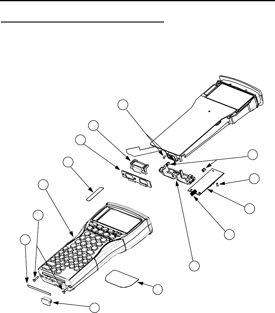
Exploded View - General Assembly
The following illustration shows the general assembly, dismantled into replaceable
subassemblies and components.
Note that the numbered circles in the illustration correspond to the items in the REF. column of
Table 1.
1
10
2
3
4
5
6
7
8
9
11
12
13
14

Confidential – Enterprise Computing Ltd
Workabout MX Service Manual
Version 2.0 8
Table 1
REF. DESCRIPTION QTY
1 LBL BOTTOM 1
LBL BTM RS232/LIF 1
LBL BTM IRDA/LIF 1
2 SCREW M2.5x10MM POZ.CS 2
3 MX ALPHA CASE + LATCH 1
MX NUMERIC CASE + LATCH 1
MX SCANNER CASE + LATCH 1
MX SCANNER NUMERIC CASE + LATCH 1
4 LBL MX 2MB MEMORY 1
5 BOTTOM SEAL 1
6 MLDG D-TYPE BLANK 1
MX BTM FLEXI IRDA 1
MX BTM FLEXI RS232 1
7 SCREW M2x4MM PANHEAD BLACK 2
8 NUTSERTS 2
9 SCREW M2x4MM PANHEAD BLACK 2
10 EXPANSION PCB (Barcode/Wand) 1
DECODER PCB (Scanner) 1
DECODER PCB SUPPORT MOULDING (Scanner) 1
11 DRAWER SPRING 1
12 CONNECTOR BLOCK 1
13 LBL MX REAR CASE 1
LBL MX SCANNER REAR 1
14 LIF DUST COVER 1
Confidential - PSION ENTERPRISE COMPUTING LTD
Workabout MX Service Manual
Version 2.0 9
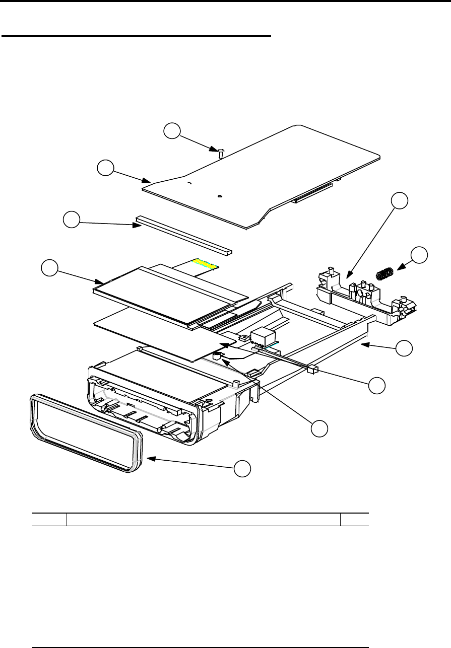
Exploded View - Chassis Assembly
The following illustration shows the chassis assembly, dismantled into replaceable
subassemblies and components.
Note that the numbered circles in the illustration correspond to the items in the REF. column of
Table 2.
1
2
3
4
5
6
7
8
10
9
Table 2
REF. DESCRIPTION QTY
1 LCD MODULE (240x100) 1
2 FOAM LCD SUPPORT 1
3 MX PCB 2MB 1
4 SCREW M2x4MM PANHEAD BLACK 1
5 CONNECTOR BLOCK 1
6 DRAWER SPRING 1
7 CPU FRAME 1
8 LCD BACKLIGHT 1
9 LCD SLEEVE 1
10 CHASSIS SEAL 1
Confidential – Enterprise Computing Ltd
Workabout MX Service Manual
Version 2.0 10
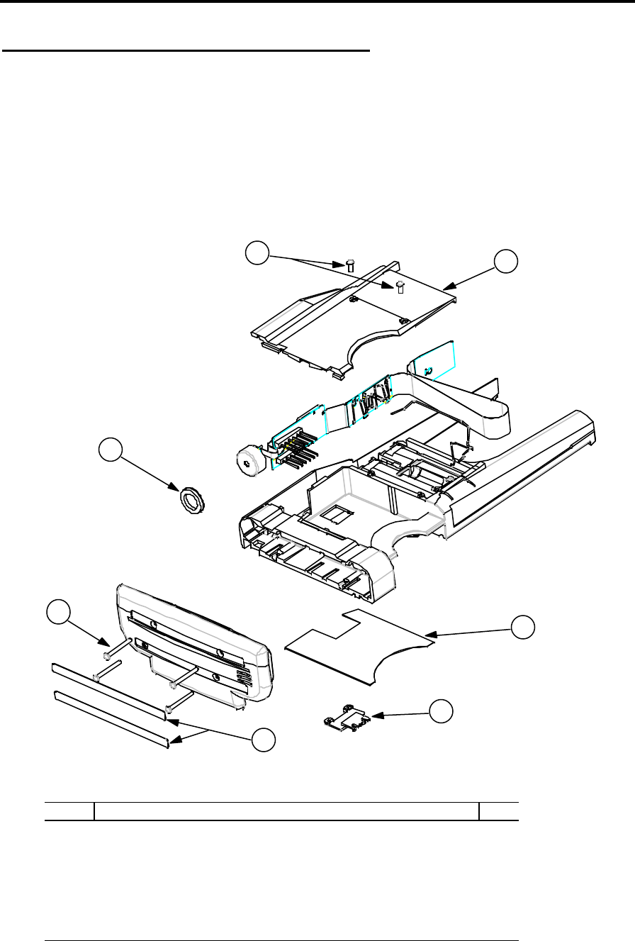
Exploded View - Drawer Assembly
The following illustration shows the Drawer Assembly, dismantled into subassemblies and
components.
+ Note: - The Drawer Assembly is normally replaced as a complete kit (see Spares Kits on
page 11). It is therefore not necessary to dismantle the Drawer Assembly. This illustration is
included for information purposes only.
Note that the numbered circles in the illustration correspond to the items in the REF. column of
Table 3.
1
6
2
34
5
7
Table 3
REF. DESCRIPTION QTY
1 SCREW M2x16MM TOP CAP 4
2 FOAM PIEZO SEAL 1
3 SCREW M2x4MM PANHEAD BLACK 2
4 SSD BACK 1
5 BATTERY CONFIGURATION LABEL 1
6 LITHIUM BATTERY DOOR 1
7 TOP CAP LABEL - BLANK 2
Confidential - PSION ENTERPRISE COMPUTING LTD
Workabout MX Service Manual
Version 2.0 11
Spares Kits
Please refer to the latest spares list, held on the web site, for current information.
Dismantling the Workabout
The modular design of the Workabout is such that the internal workings of the product can be
removed from the case by removing two screws. This means that if the outer case assembly
becomes damaged, it can be replaced quickly and easily without the need to change any other
component. If there is a fault in the Outer Case Moulding, LCD Window, Keyboard Frame, or
Rubber Key mat, the entire case should be replaced.
+ Note: - In some cases the machine may be fitted with security screws that require a suitable
screwdriver to remove them.
When you remove internal components from the case, take care not to damage the LCD
Module. Do not bend the Module, as it is prone to fracturing. Do not touch the LCD Glass, as it
will show finger marks and smudges.
If the LCD glass is broken, be careful not to get any liquid in your mouth or eyes. In the event of
any liquid crystal getting on skin or clothes, wash it off immediately with soap and plenty of
water and seek a doctor’s advice.
Tools Required
Tool Description Type
Crosshead Screwdriver Pozi Size - 0
Crosshead Screwdriver Phillips Size - 00
Screwdriver Flat Size - 2.5mm
Nut Spinner n/a 4mm AF
Knife/Scalpel n/a n/a
Pliers Snipe nose n/a
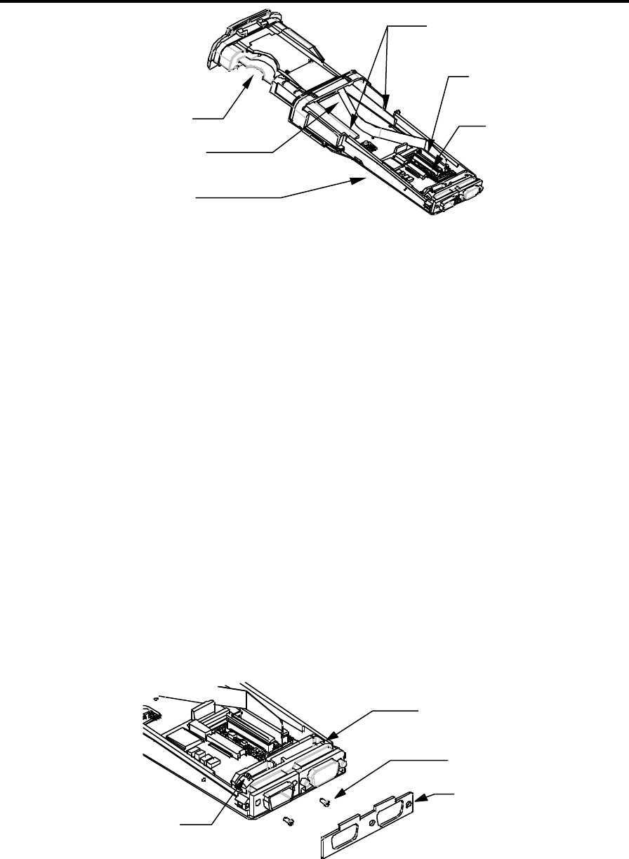
Dismantling Procedure
1 Press the drawer release button (or use a security key if necessary) and open the
Workabout.
2 Remove any batteries (including the Lithium Dry Cell) and SSDs that are inside the
Workabout.
3 Remove the fuse from its location beneath the main batteries. If the fuse is damaged, replace
it with a 1.25 AMP ‘Fast Blow’ glass fuse, 5mm ∅, 20mm long, Psion part number A4900-
0041.
4 Remove the 2 screws from the base of the Workabout.
5 Pull the Chassis Assembly from the case (this may require a sharp tug).
6 If fitted, unclip the Option Flexi from its ZIF Connector on the Main PCB and also from the
ZIF Connector(s) on the Expansion or Monitor PCB.
+ Note: - Take care not to crease or tear the Flexi.
Confidential – Enterprise Computing Ltd
Workabout MX Service Manual
Version 2.0 12
Drawer Assembly
Main Power Flexi
Drawer Locating Clips -
Derail from the Chassis
Option Flexi ZIF
Connector
Main Power Flexi
ZIF Connector
Chassis Assembly
7 Unclip the Main Power Flexi from its ZIF Connector.
8 Unclip the Drawer Assembly by derailing the Drawer from its tracks.
9 Slide the Drawer Assembly out of the Chassis Assembly.
+ Note: - Dismantling the Latch Assembly is not necessary as replacement cases are supplied
complete with latches. The following step is for information only.
10 To remove the Latch Assembly, remove the 3 screws from the latch case. Be careful to
catch the internal springs and other components when you remove the case.
Dismantling the Chassis Assembly
1 Remove the Drawer Spring from the Connector Block.
+ Note: - The Drawer Spring should always be removed when you either remove or refit the
Connector Block.
2 Remove the Bottom Connector Seal.
+ Note: - As a general rule, replace the Bottom Connector Seal whenever it is removed for
servicing.
3 Remove the 2 screws from the LIF Connector.
Bottom Connector Seal
LIF Connector screws
Connector Block
Drawer Spring
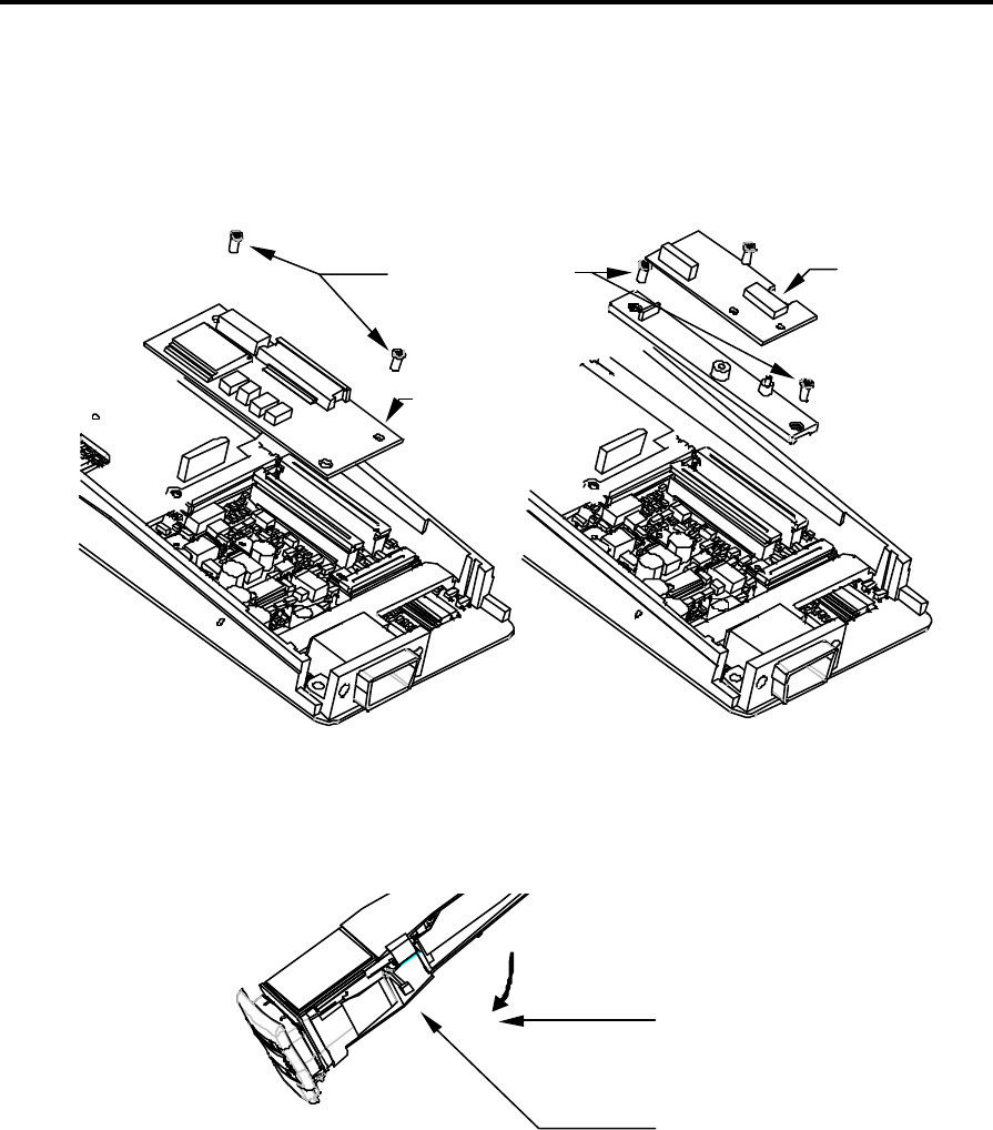
4 Remove the screw-locks for the Expansion Board D-Type Connector, if fitted.
5 Lift out the Connector Block by squeezing its arm in as near as possible to the base of the
Workabout, to allow the actuator to clear the retaining tab on the CPU frame.
Confidential - PSION ENTERPRISE COMPUTING LTD
Workabout MX Service Manual
Version 2.0 13
6 If fitted, remove the Decoder or Expansion PCB:
a) On a Scanner Workabout, remove the Flexi’s from the ZIF connectors and then remove
the 2 retaining screws on the Support Moulding.
b) On a Barcode/Wand Workabout, remove the Flexi from the ZIF connector and then
remove the 2 retaining screws.
Retaining screws
Option PCB
Scanner
Decoder
PCB
Barcode/Wand
Scanner
7 Remove the Option Port FFC, if fitted, and remove the Option Port.
8 Remove the LCD Backlight Power Connector, if fitted.
LCD Backlight
Power Connector
LCD Backlight
Power Flexi
Confidential – Enterprise Computing Ltd
Workabout MX Service Manual
Version 2.0 14
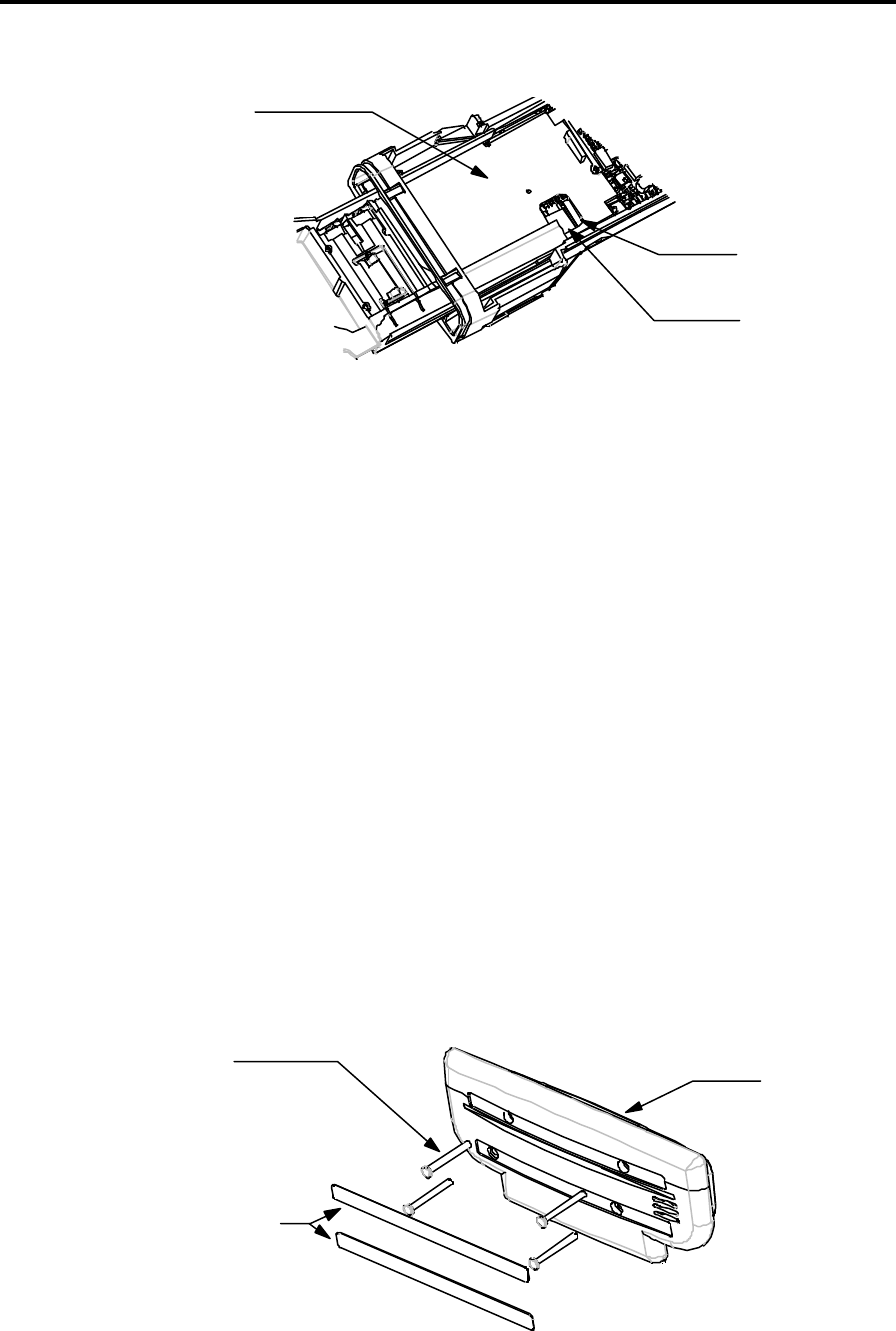
9 Unclip the LCD ZIF from the Main PCB. There is a hole in the CPU frame moulding to allow
you to do this.
LCD ZIF
Connector
LCD FFC
CPU Frame
Moulding
10 Remove the Main PCB Screw.
11 Remove the Main PCB.
12 Remove the Chassis Seal.
13 Remove the LCD. The LCD Module is located on a pin on the CPU Frame moulding. The
rubber LCD Sleeve covers this pin. Handle the LCD Module by the glass so that you do not
damage the circuit boards. Manoeuvre the module off the pin by wiggling the module while
holding the glass.
14 Remove the Backlight, if fitted.
The Chassis Assembly is now dismantled.
Dismantling the Drawer Assembly
+ Note: - It is not necessary to dismantle the Drawer Assembly. This procedure is included for
information purposes only.
1 Remove the Top Cap:
a) On base machines, labels cover the four screws that secure the Top Cap. Remove the
labels and then remove the screws.
b) On Option Machines, the screws are not covered.
Top Cap
4 screws
Labels on Base
machines
2 Remove the foam Top Cap Seal and the Piezo Seal.

Confidential - PSION ENTERPRISE COMPUTING LTD
Workabout MX Service Manual
Version 2.0 15
+ Note: - As a general rule, replace the Top Cap Seal and Piezo Seal whenever they are
removed for servicing.
3 Remove the Expansion FFC if fitted. Ease the FFC out of the case by sliding it backwards
and forwards length-ways and pulling it gently up out of the insertion slot in the SSD Drawer
moulding.
4 Remove the SSD Back. This is clipped onto the SSD Drawer at the top end. To remove it:
a) Remove the two securing screws.
b) Remove the SSD Back by lifting its free end out by about 10mm and then prying the top
left-hand corner away from the SSD Drawer moulding until it becomes unclipped. Take
care not to damage the Lithium Battery Contacts on the FFC.
5 Release the Piezo. The tail that connects the Piezo to the Main Power FFC is quite thin and
can be damaged if not handled correctly. Take care to release the strip of the FFC attached
to the Piezo at the same time that the rest of the Main Power FFC assembly is eased out of
the SSD Drawer.
6 Remove the Fuse Contacts.
The Drawer Assembly is now fully dismantled.
Selecting the PCB Type
The Workabout Main PCB can be programmed for Scanner, Integral Wand, or Numeric versions
by using a Workabout Final Test Box.
The Main PCB is supplied programmed as Type B (Top port - TTL & RS232) and the Workabout
Final Test Box allows you to select the PCB type using the product type/variant code as listed
in the section Serial Number Information on page 2.
Confidential – Enterprise Computing Ltd
Workabout MX Service Manual
Version 2.0 16
Re-assembly Instructions
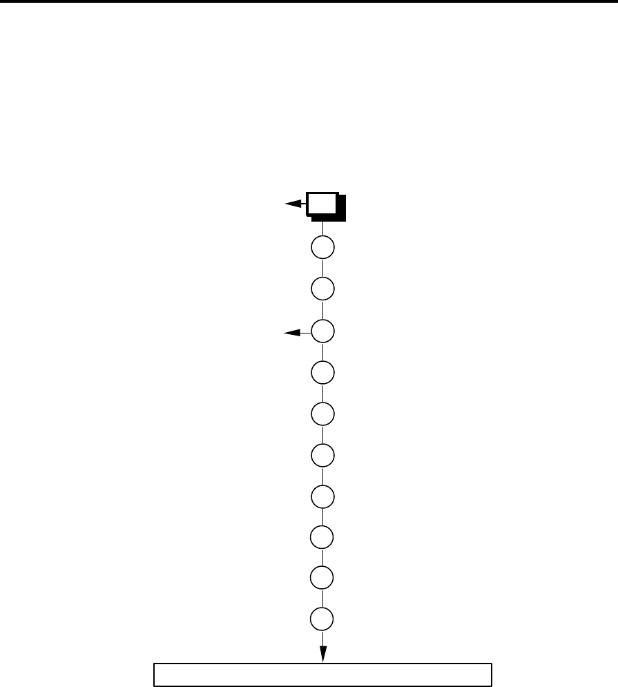
The Workabout can be re-assembled by following the flow diagrams below.
The flow diagrams show the correct sequence for re-assembling the subassemblies. Also refer
to the diagrams in the Dismantling Procedure steps on page 11, in reverse order, as you perform
each re-assembly step.
Take care when you reinsert Flexi’s into ZIF Connectors. If you insert Flexi’s into the connectors
at an angle, it can cause open or short-circuits.
Make sure that the bends in the Flexi’s allow the drawer to open and close correctly.
Re-assembling the Drawer Assembly
1
2 Insert the Piezo and Main Power Flexi
assembly.
Insert the Fuse Contacts.
See Notes Step 2 below
3 Fit the SSD Back.
See Notes Step 3 below
4 Fit the 2 securing screws.
5 Insert the Option Flexi (if fitted).
See Notes Step 5 below
6 Fit a new Top Cap Seal.
7 Fit a new Piezo Seal.
8 Screw the Top Cap to the Drawer
Assembly.
The Drawer Assembly has now been re-assembled.
9 Apply End Cap labels.
No
Yes
Base machine?
Notes on Drawer Re-assembly
Step 2
Take care when sliding the Piezo tail into the SSD Drawer via the insertion slot.
Confidential - PSION ENTERPRISE COMPUTING LTD
Workabout MX Service Manual
Version 2.0 17
Step 3
Take care not to damage the Main Battery and Lithium Battery contacts.
Step 5
Ease the FFC into the case by sliding it backwards and forwards while pushing it gently down
through the insertion slot in the SSD Drawer moulding.
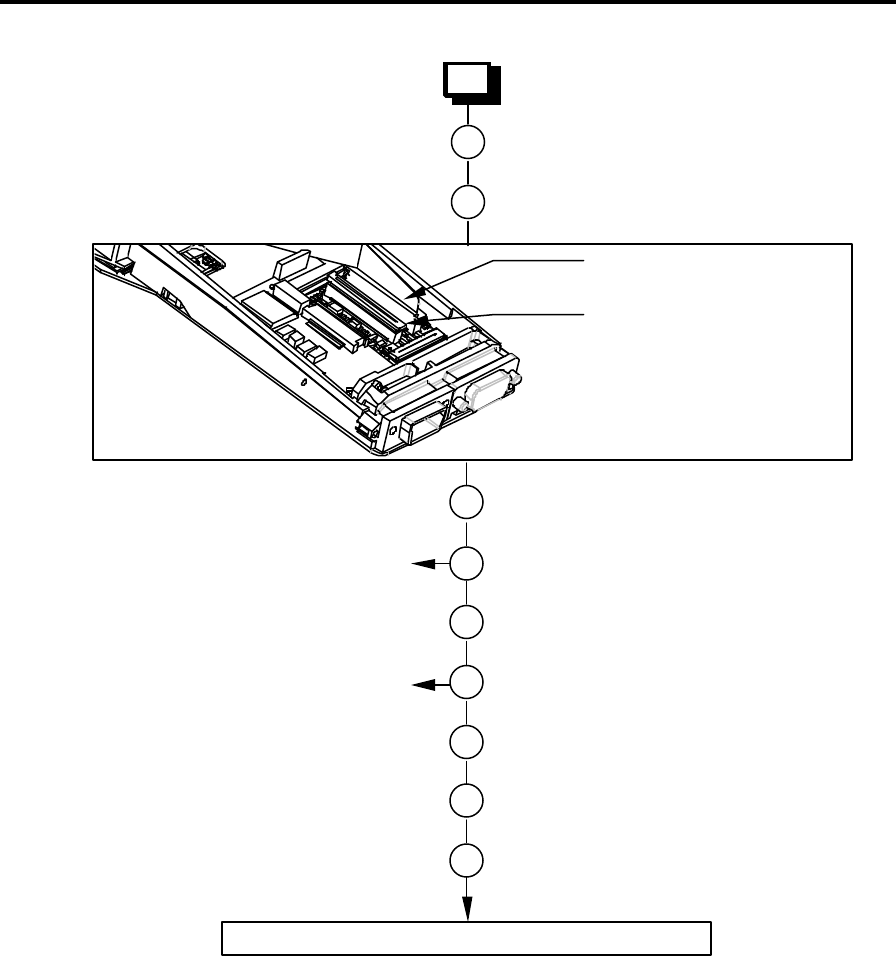
Re-assembling the Chassis Assembly
1
2 Fit the LCD on top of the Backlight.
Place the Backlight, if fitted, in position.
3 Fit the Chassis Seal.
4 Fit the Main PCB.
5 Connect the Backlight Power Connector.
6 Fit the Option Port Flexi or Blank.
7 Add the Option or Decoder PCB, if fitted.
8 Fit the Connector Block.
The Chassis Assembly has now been re-assembled.
11
Fit the Drawer Spring.
See Notes Step 1 below
See Notes Step 4 below
9 Fit the 2 LIF Connector Screws.
10
Fit a new Bottom Connector Seal.
Notes on Chassis Re-assembly
Step 1
Stick the LCD Backlight Flexi to the side of the Chassis Assembly.
Step 4
Hold the Main PCB and Chassis Assembly parallel to each other and insert the LCD Flexi into
the LCD ZIF Connector. Lock the ZIF Connector. Now fit the Main PCB Screw.
Confidential – Enterprise Computing Ltd
Workabout MX Service Manual
Version 2.0 18
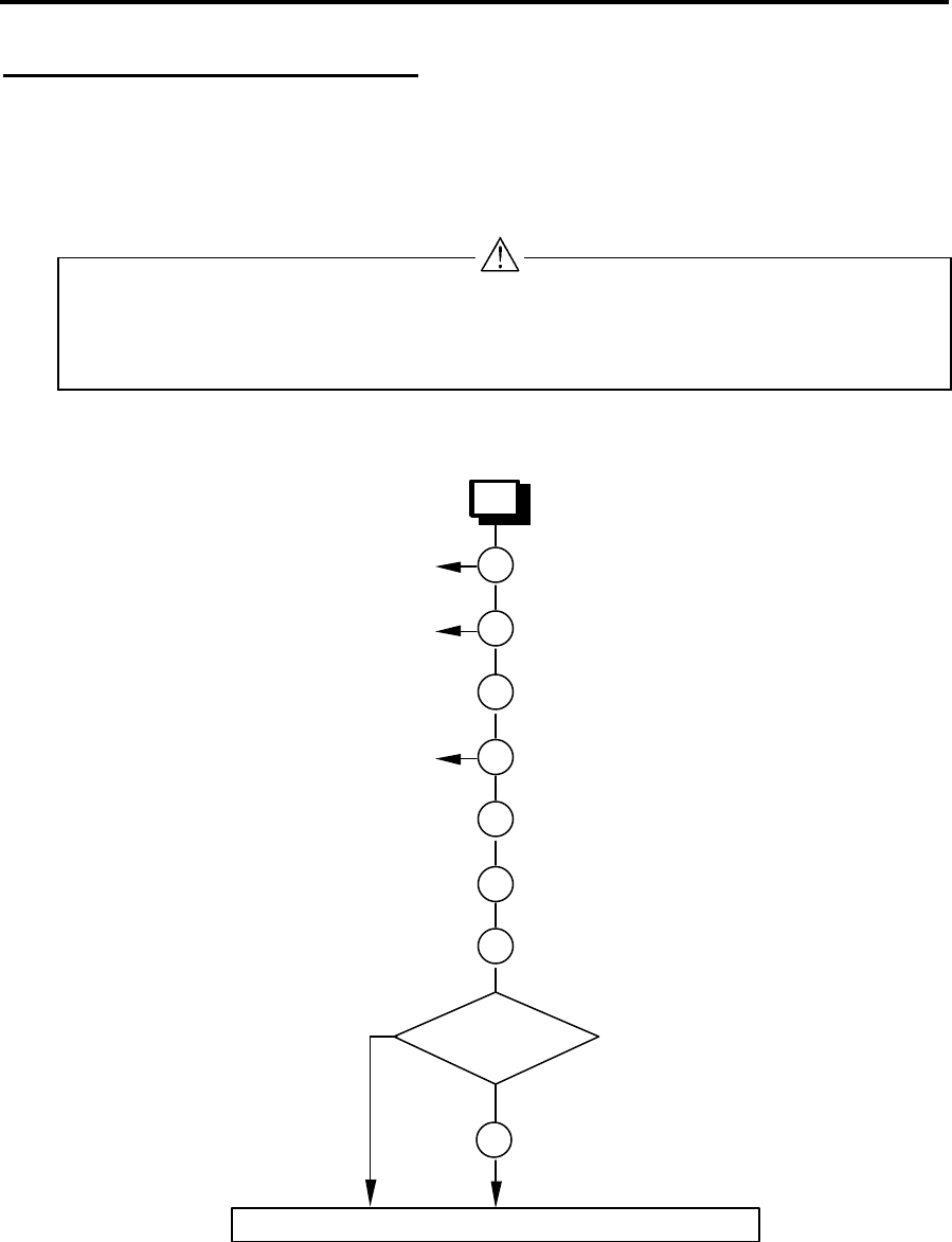
Final Re-assembly
1
2 Locate the Drawer rails in their tracks.
Slide the Drawer Assembly into the
Chassis Assembly.
3 Connect the Main Power Flexi to its ZIF
Connector.
4 If fitted, connect the Expansion Flexi to its
ZIF Connectors.
5 Insert the Chassis Assembly into the case.
6 Fit 2 screws in the base of the case.
7 Insert the fuse.
8 Insert the Main and Lithium Batteries.
The Workabout has now been re-assembled.
9 Insert the SSDs.
10
Close the Workabout Drawer.
See Notes Step 5 below
See Notes Step 7 below
Option ZIF Connector
Main Power ZIF Connector
Notes on Final Re-assembly
Step 5
Take care to ensure that the Chassis Seal fits correctly.
Step 7
The fuse must be a 1.25 AMP ‘Fast Blow’ glass fuse, 5mm ∅, 20mm long, Psion part number
A4900-0041.
Confidential - PSION ENTERPRISE COMPUTING LTD
Workabout MX Service Manual
Version 2.0 19
Checking the Operation of the Options
To accurately check the operation of fitted options, you need the following items:
n A bar code reader or a scanner that gives a TTL output.
n An RS232 interface.
n A bar code wand or scanner with a 9-way male connector with the following pin arrangement:
Pin No. Signal
Name Remarks
1 DCD Handshake - input
2 RX Bar Code Data Receive - input
3 GND 0V
4 GND 0V
5 DSR Handshake - input
6 DTR Handshake (Trigger or Enable) - output
7 GND 0V
8 GND 0V
9 VCCEXT 5V 200mA max
n An IBM-compatible PC able to run VT in MS-DOS or Terminal in Windows 3.1x. Any other
program that can be run to provide Glass Terminal Emulation can also be used.
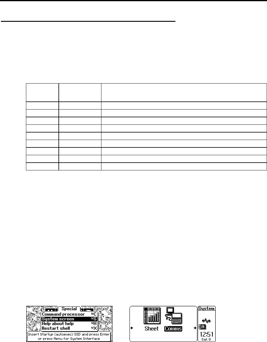
Checking the RS232 Interface
You can use the Comms application on the Workabout to turn on the RS232 interface on the
option board and check the RS232 interface. To check the RS232 interface:
1 Switch on the Workabout.
Switching the machine on after replacing a backup battery, or for the first time, causes the
Workabout to reboot. When you press the On button, the Workabout beeps and after a
pause of up to 5 seconds, the shell screen appears.
2 Press the Menu key.
3 Use the cursor keys to select the System screen option and press Enter.
4 On the System screen, use the cursor keys to position the highlight bar over the Comms
application and press Enter.
5 Plug a 9-way female to 9-way female null modem cable between the serial port on the PC
and the RS232 port on the Workabout.
6 On the PC, run VT in MS-DOS, or Terminal in Windows 3.1x. The default baud rate for the
RS232 port in the Workabout is 9600. Adjust the settings on the PC program to match.
Confidential – Enterprise Computing Ltd
Workabout MX Service Manual
Version 2.0 20
7 When a serial link has been established between the PC and the Workabout, any characters
you type on the Workabout appear on the PC screen and vice-versa. This indicates that the
RS232 serial channel is working correctly.
8 To exist from the Comms program, press + on the Workabout.
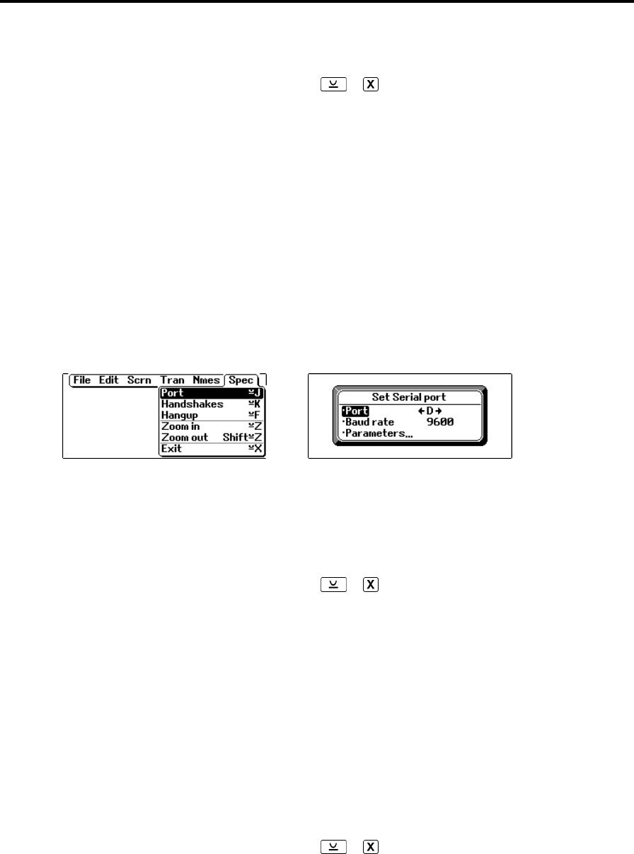
Testing the TTL Interface
You can test the TTL interface by using a compatible barcode device. To do this, follow steps 1
to 4 of the RS232 Interface check procedure and then follow the steps below:
1 Plug a compatible barcode device into the TTL port.
2 If the barcode device is giving true data, set the expansion board port to D. If it is giving
inverted data, set the port to G:
a) In the Comms application, press Menu and select Spec. (Use the ↑ and ↓ keys to
select an item and the ← and → keys to select a value.)
b) Set the baud rate to 9600 and the port to D or G as appropriate.
3 Scan some sample bar codes. The numerical equivalent of the barcode should appear in the
top left corner of the screen.
+ Note: - Always scan at least two different barcodes to ensure that a chance operation has not
occurred.
4 To exist from the Comms program, press + on the Workabout.
Testing the Barcode Interface
The Barcode interface can be tested using a compatible barcode wand or scanner. To do this,
follow steps 1 to 4 of the RS232 Interface check procedure and then follow the steps below:
1 Plug a compatible barcode device into the Barcode port.
2 Set the expansion board port to E and set the baud rate to 9600 (refer to the Testing the TTL
Interface instructions).
3 Scan some sample bar codes. The numerical equivalent of the barcode should appear in the
top left corner of the screen.
4 To exist from the Comms program, press + on the Workabout.

Confidential - PSION ENTERPRISE COMPUTING LTD
Workabout MX Service Manual
Version 2.0 21
Expansion Interface
The interfaces built into the Workabout are accessible by plugging in appropriate connectors or
adapters at the top or bottom of the unit.
The top connectors provide RS232 AT and either a TTL-level serial interface or a bar code wand
interface. The TTL-level serial interface can operate CCD barcode scanners or low power laser
scanners.
The bottom connector provides access to the LIF connector for the docking interface, external
power and SIBO serial interfaces.
Optional internal peripheral modules provide the serial and barcode interfaces. These are fitted
inside the Workabout and plug into an internal expansion connector.
RS232 AT/TTL Serial Interfaces
These are provided by the RS232 AT/TTL peripheral module, which provides:
n An IBM-compatible RS232 AT serial interface at standard RS232 voltage levels
n An RS232 TTL serial interface at 5V TTL levels
n A 5V nominal (4.7V min.) software switched power supply (VCCEXT) which provides up to
200 mA, with a current limit at approximately 250mA
The serial format and the polarity of the TTL-level interface can be programmed using suitable
software programs. The interfaces can be operated at a baud rate of 19,200.
+ Note: - Although both interfaces are present in the module, only one can be configured as
operational at any one time.
The 9-way D-type male RS232 AT interface connector pin allocation is shown below:
Pin No. Signal
Name Remarks
1 DCD Handshake - input
2 RX Serial Receive - input
3 TX Serial Transmit - output
4 DTR Handshake - output
5 GND 0V
6 DSR Handshake - input and EXON (1)
7 RTS Handshake - output
8 CTS Handshake - input
9 GND 0V
(1) The EXON signal is the external wake-up control for the Workabout. If the RS232 AT/TTL peripheral
expansion module is configured correctly, the EXON signal switches on the Workabout when an
RS232 or TTL-level rising edge is applied to this signal. The RS232 AT interface is enabled by
opening port A (see Testing the TTL Interface on page 20 for instructions on how to do this).

Confidential – Enterprise Computing Ltd
Workabout MX Service Manual
Version 2.0 22
The 9-way D-type female RS232 AT interface connector pin allocation is shown below:
Pin No. Signal
Name Remarks
1 GND 0V
2 RX Serial Receive - input
3 TX Serial Transmit - output
4 VCCEXT 5V 200mA max (1)
5 GND 0V
6 DSR Handshake - input
7 RTS Handshake - output
8 CTS Handshake - input
9 GND 0V
(1) The VCCEXT supply is switched on and off at the same time as the TTL serial port is opened and
closed. The RS232 TTL interface is enabled by opening port D for true data and port G for inverted
data (see Testing the TTL Interface on page 20 for instructions on how to do this).
RS232 AT Serial/Barcode Interfaces
These are provided by the RS232 AT/Barcode peripheral module, which provides:
n An IBM-compatible RS232 AT serial interface at standard RS232 voltage levels at up to
19,200 baud
n An RS232 TTL serial interface at 5V TTL levels
n A 5V nominal (4.7V min.) software switched power supply (VCCEXT) which provides up to
200 mA, with a current limit at approximately 250mA
n A barcode wand interface with a 5V nominal (4.7V min.) software switched power supply
(VCCEXT) which provides up to 200 mA
The RS232 AT interface serial format can be programmed using suitable software programs and
a Hewlett Packard HBCR-1612 barcode decoder device provides the barcode interface. This
allows wands, which generate digital signals to be connected directly to the barcode interface.
The barcode interface format can be programmed using software, although this feature is not
used if a Hewlett Packard barcode wand is being used, as the decoder requires a set format.
+ Note: - Although both interfaces are present in the module, only one can be configured as
operational at any one time.

Confidential - PSION ENTERPRISE COMPUTING LTD
Workabout MX Service Manual
Version 2.0 23
The 9-way D-type male RS232 AT interface connector pin allocation is shown below:
Pin No. Signal
Name Remarks
1 DCD Handshake - input
2 RX Serial Receive - input
3 TX Serial Transmit - output
4 DTR Handshake - output
5 GND 0V
6 DSR Handshake - input and EXON (1)
7 RTS Handshake - output
8 CTS Handshake - input
9 GND 0V
(1) The EXON signal is the external wake-up control for the Workabout. If the RS232 AT/TTL peripheral
expansion module is configured correctly, the EXON signal switches on the Workabout when an
RS232 or TTL-level rising edge is applied to this signal. The RS232 AT interface is enabled by
opening port B (see Testing the TTL Interface on page 20 for instructions on how to do this).
The 9-way D-type female RS232 AT interface connector pin allocation is shown below:
Pin No. Signal
Name Remarks
1 DCD Handshake - input
2 RX Bar Code Data Receive - input
3 GND 0V
4 GND 0V
5 DSR Handshake - input
6 DTR Handshake (Trigger or Enable) - output
7 GND 0V
8 GND 0V
9 VCCEXT 5V 200mA max (1)
(1) The VCCEXT supply is switched on and off at the same time as the barcode port is opened and
closed. The barcode interface is enabled by opening port E (see Testing the TTL Interface on page
20 for instructions on how to do this).
+ Note: - The Hewlett Packard barcode decoder uses 9600 baud, true data port settings.
Circuit Description
LIF Converter
The LIF Converter provides the interface between the mains adaptor, serial link and the
Workabout. It also includes a charging circuit in the form of a linear regulator operating in
constant current mode.
Confidential – Enterprise Computing Ltd
Workabout MX Service Manual
Version 2.0 24
Final Test
The section describes how to set up the Final Test and perform the test sequence on a
Workabout.
+ Note: - Please refer to Appendix A for instructions on how to test the Workabout expansion
options.
These instructions do not describe how to perform tests on the Workabout Peripheral product
range.
Equipment
You need the following equipment to perform the Final Test:
Qty Description Psion p/no.
1 Workabout Final Test Unit 1810-0001-01
1 Mains Lead
2 Test SSDs
1 Workabout Test Battery Cartridge
1 LIF Cable
1 Lithium Battery
+ Note: - The Final Test Unit is suitable for working with mains supplies in the range
90-130/180-260VAC @ 47-63Hz, without adjustment.
Test Set-up
WARNING - There are hazardous voltages within the Final Test Unit. Please follow this
procedure carefully.
Follow the steps below to set up a Workabout for testing.
1 Insert the following items in the Workabout:
q 2 x test SSDs (MX Only)
q 1 x lithium battery
q 1 x Workabout Test Battery Cartridge
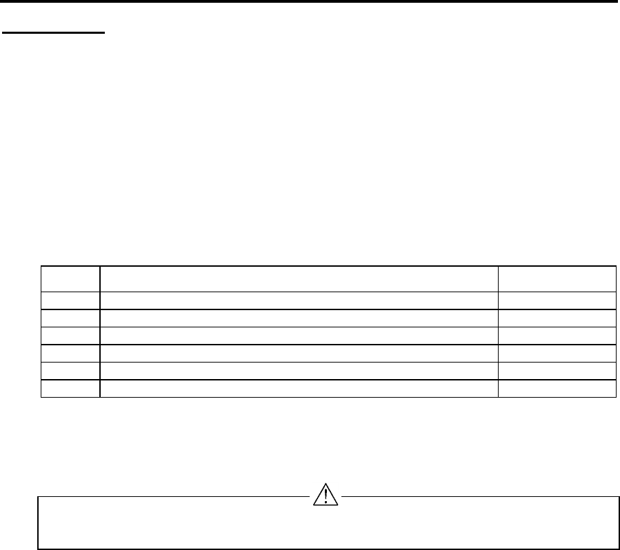
2 On the Final Test Unit:
a) Connect the LIF Cable and Ground Detect Probe to the Final Test Unit.
b) Set the main battery switch to STANDBY.
c) Set the DC Power switch to OFF.
Confidential - PSION ENTERPRISE COMPUTING LTD
Workabout MX Service Manual
Version 2.0 25
WORKABOUT
FINAL TEST UNIT
EXP SUPPLY OK
BAT. GROUND FAULT
THERMISTOR FAULT
STANDBY
ON
OFF
ON
BATTERY CURRENT
GROUND DETECT PROBE
LIF CONNECTOR
A
Insert the LIF
Connector
Insert the Ground
Detect Probe
Main Battery switch
to STANDBY DC Power
switch to OFF
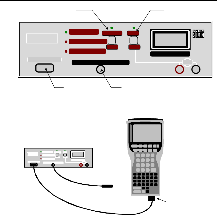
3 Connect the LIF Connector to the Workabout. The LIF connector provides power to the
Workabout:
Final Test Unit
LIF Connector
Workabout unit
contains:
n Lithium battery
n 2 x test SSDs
(MX Only)
n Workabout Test
Battery Cartridge
Ground
detect
probe
The Workabout is now ready for testing.
Test Sequence
1 Check the battery standby current reading on the Final Testing Unit ammeter.
Fail the 2M SR-DRAM unit if the reading is higher than 750µA.
2 Check that the THERMISTOR FAULT lamp is not lit.
3 Move the Main Battery switch from STANDBY to ON.
4 The EEPROM setting will be displayed and the serial number is required to be entered. The
serial number information is detailed on page 2 of this manual.
5 Each field should be correctly filled by using the arrow keys to select the field, and entering
the existing serial number displayed on the Workabout drawer. The variant settings can be
verified against the information given on page 3 of this manual.

Confidential – Enterprise Computing Ltd
Workabout MX Service Manual
Version 2.0 26
6 Once compete, press MENU to program. The Final Test Program is downloaded via
the LIF cable, and the following menu is displayed on the Workabout:
MENU - FINAL - MX - ‘Version Number’
‘O/S’ RAM ‘size’ LANG ‘language’
All
Cpu
SSDs
Ram
Lcd
Serial
Sound
Drawer
Keys
Supply
Expansion
Arrow keys move, ENTER selects
MENU - FINAL - RF - ‘Version Number’
‘O/S’ RAM ‘size’ LANG ‘language’
All
Cpu
MMC
Ram
Lcd
Serial
Sound
Drawer
Keys
Supply
Expansion
Arrow keys move, ENTER selects
Check the following:
a) The Final Test Program Version Number corresponds to the latest release.
b) Check that the Operating System version number, RAM size and Language settings are
correct.
c) Check the ammeter reading on the Final Test Unit. Fail the unit if the reading is higher
than 25mA for MX.
+ Note: - You can perform each check individually by selecting each option in turn from the
test menu. This procedure uses the all option to run through all the checks in one go.
7 Select the All option from the test menu on the Workabout and press Enter.
A bold centre cross and a corner marker are displayed. The cross should be bold and even
throughout and all corners should be complete, as shown in the example below:
8 Press any key to continue.
9 If the pattern is correct press Space. If the pattern is faulty press Esc.
10 Check that the LCD backlight is now ON.
11 Check the contrast range:
a) Press any key - the screen should be black.
b) Press any key - the screen should be clear.
c) Press any key a third time - the screen should return to normal.
If the maximum and minimum contrast were correct, press Space. If they were not correct,
press Esc.
Confidential - PSION ENTERPRISE COMPUTING LTD
Workabout MX Service Manual
Version 2.0 27
12 Check all the Workabout keys:
a) Press any key to begin. A full keyboard map is displayed.
b) Press each key in turn and note that the selected key image changes from dark grey to
light grey.
13 When you are prompted to “Switch on the DC Supply”, move the DC Power switch on the
Final Test Unit to ON.
14 Check the battery ammeter reading. It should be zero. Check also that the DC Supply
indicator (the green LED on the Final Test Unit) is lit.
15 Check that the buzzer sounds. If the buzzers sounds press Space. If the buzzer does not
sound press Esc.
+ Note: - Check on the Final Test Unit, that the EXP SUPPLY OK indicator is lit.
16 The Expansion Tests Menu will be displayed. To run these optional tests you will need
additional hardware which is detailed in Appendix A. To skip these tests select the bottom
menu item (“Expansion Test Exit”) and press ENTER. Press SPACE when prompted to
continue testing if the “All” option was selected.
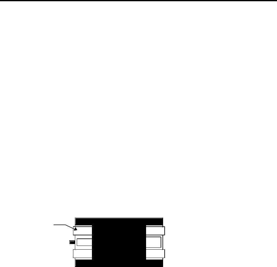
17 When you are prompted to “Open Drawer”, open the Workabout and check the Battery
Ground contact by touching the ground connection on the test battery cartridge with the
ground detect probe:
Ground
Workabout Test Battery Cartridge
The BATTERY GROUND FAULT indicator should go off when the probe touches the metal.
18 Remove the solid-state disks, battery pack and lithium battery.
19 Close the drawer and press any key.
If all the tests have been passed, press Space to continue.
20 Remove the LIF Connector from the Workabout.
The final test for MX/RF is now complete.
+ Note: - If the test failed, remove the LIF Connector and set up the Workabout again, but
when the test menu is displayed, select each test in turn from the test menu until you find the
test that fails.

Confidential – Enterprise Computing Ltd
Workabout MX Service Manual
Version 2.0 28
Scanner Test
The section describes how to set up and perform Scanner Test on a Workabout MX/RF.
+ Note: - These instructions do not describe how to perform tests on the Workabout Peripheral
product range.
Equipment
You need the following equipment to perform the Test:
Qty Description Psion p/no.
1 Any Bar code
2 AA Batteries
Set - up
1 Remove any lithium that may be in the UUT. Insert AA batteries observing polarity, close the
drawer.
Test Sequence
1 This test instruction details the procedure to perform a post final scanner on a Workabout
MX/RF
2 Press the On/Esc key, which is located on the top left of the unit
3 You will now see the PSION main screen
4 Press and hold down the Psion key (Bottom left, a line with a u above it) and then the S key,
and then release the keys
15 Now use the CURSOR keys to move along to the right of the screen to select the Demman
application and press enter
16 Now select the BARCODING DEMO using the CURSOR keys - ENTER to select
17 If Scanner used for the first time use the ARROW keys to select scanner type - Symbol 2
and press ENTER, otherwise verify that the scanner type is Laser 1223 - indicated at the top of
the screen
18 At this point, you will most likely get an error, and be told that the program is exiting - this is
fine, let it drop you back to the Demman screen, and just re-select the BARCODING DEMO - it
should now work and say Laser 1223
19 Scan a bar code, and if the UUT displays the bar code number correctly, pass the unit,
otherwise fail it.
20 Switch off the unit.
20 Remove the batteries from the UUT
Scanner test is now complete

Confidential - PSION ENTERPRISE COMPUTING LTD
Workabout MX Service Manual
Version 2.0 29
Appendix A - Workabout Expansion Option Tests
The Workabout Final Test Unit incorporates tests for many of the available expansion options. These
tests are not fully automated since the test requirements vary depending on machine type, the
expansion options fitted and individual configuration options. Finally, these tests require additional
hardware (loopback plugs etc) which may not always be available; the selection and operation of these
tests is therefore entirely under the control of the user.
These tests provide a quick and simple method of thoroughly testing the expansion options. The
various alternative tests, described elsewhere in this manual, may still be used if preferred.
Hardware Requirements
Qty Description Psion Part No.
1 Workabout Final Test Unit 1810-0001-01
1 Mains Lead
1 LIF Cable
1 Any Suitable Barcode (For Scanner Tests) N/A
1 Female Loopback Connector (For testing RS232 ports) 1810-0002-01
1 Male Loopback Connector (For testing TTL ports) 1810-0003-01
1 IrDA Mirror Unit (For testing units with IrDA ports) 1810-0004-01
1 Extended Systems “XTNDAccess IrDA PC Adapter” -
(ESI-09680)
For use in conjunction with the “IrDA Mirror Unit” and
therefore only required for testing units with IrDA ports.
A7821-0002-01
+ Note: - Connection details for making loopback plugs may be found at the end of this
Appendix.
The Expansion Menu
The various Expansion Tests are available through the Main Menu either by selecting “Expansion” or
as part of the “All” option. When selected, the following Menu to be displayed:-
EXPANSION – FINAL-MX 2.04A
RS232 Loopback Test
IrDA Loopback Test
TTL Loopback Tests
Scanner Tests
Expansion Test Exit

Confidential – Enterprise Computing Ltd
Workabout MX Service Manual
Version 2.0 30
Arrow keys move, ENTER selects
When testing is complete, select the bottom menu item (“Expansion Test Exit”) and press
ENTER.
RS232 Loopback Test
1. Select the RS232 test from the UUT menu and press ENTER.
2. Attach the RS232 loopback plug to the RS232 port of the UUT.
3. The RS232 port is normally defined as TTY:A. Use the arrow keys to alter this setting
if necessary. The SPACE key will list all available ports.
4. Press ENTER to test. A Pass or Fail message will be displayed.
TTL Loopback Test
1. Select the TTL test from the UUT menu and press ENTER.
2. Attach TTL loopback plug to the TTL port of the UUT.
3. The TTL port has two modes of operation – “Normal” and “Inverted”. These are
normally mapped to TTY:D and TTY:G respectively. Use the arrow keys when prompted to
alter the port letters if necessary. The SPACE key will list all available ports.
4. Press ENTER to test the “Normal” mode.
5. Repeat Steps 3 and 4 when prompted to test the “Inverted” mode.
IrDA Loopback Test
This test requires the IrDA Mirror test equipment. Essentially, this is a small box, powered by an
external power unit and connected to an Extended Systems “Jet-Eye”
1. Set up the “IrDA Mirror” The red “Power” LED should be ON. The green and amber
LED’s will flash briefly when power is first applied after which they should be OFF to indicate
that the IrDA Mirror is ready.
2. Select the IrDA test from the UUT menu and press ENTER.
3. Select the “Top” or “Bottom” IrDA port, as appropriate for the UUT. Note: If the UUT
has two IrDA ports then you will need to repeat the procedure to test both the “Top” and
“Bottom” options in turn.
4. The IrDA port is normally defined as TTY:R. Use the arrow keys to alter this setting if
necessary. The SPACE key will list all available ports.

Confidential - PSION ENTERPRISE COMPUTING LTD
Workabout MX Service Manual
Version 2.0 31
5. Point the IrDA window on the UUT at the Jet-Eye connected to the IrDA Mirror.
6. Press ENTER to test. A Pass or Fail message will be displayed.
Scanner Tests
Note: Before running this test ensure that the “DC Power Switch” on the Workabout Final Test Unit is
set to ON.
Note: This test does not currently support the Long Range Scanner option.
1. Select “Scanner Tests” from the expansion menu.
2. Point the Scanner at any suitable barcode.
3. Press ENTER to start the scanner.
4. A successfully read barcode will be displayed . A fail message will be displayed if a valid
barcode is not read within a short period.
5. Press ENTER (twice) to repeat the test.
Loopback Connector Details
The loopback plugs consist of a 9 Way “D” type connector with various pins connected together by
means of short wire links. The pins which need to be linked together are shown in the table below:-
RS232 Loopback – 9 Way Female “D” TTL Loopback – 9 Way Male “D” Type
1 Link to pins 4 & 6 1 Link to pins 4 & 6
2 Link to pin 3 2 Link to pin 3
3 Link to pin 2 3 Link to pin 2
4 Link to pins 1 & 6 4 Link to pins 1 & 6
5 No Connection 5 No Connection
6 Link to pins 1 & 4 6 Link to pins 1 & 4
7 Link to pin 8 7 Link to pin 8
8 Link to pin 7 8 Link to pin 7
9 No Connection 9 No Connection
-END-