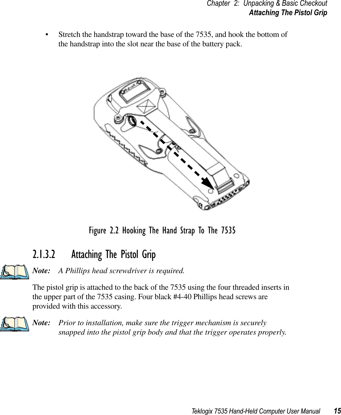
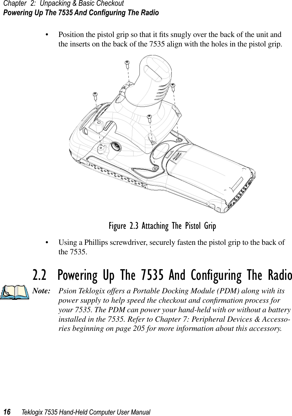
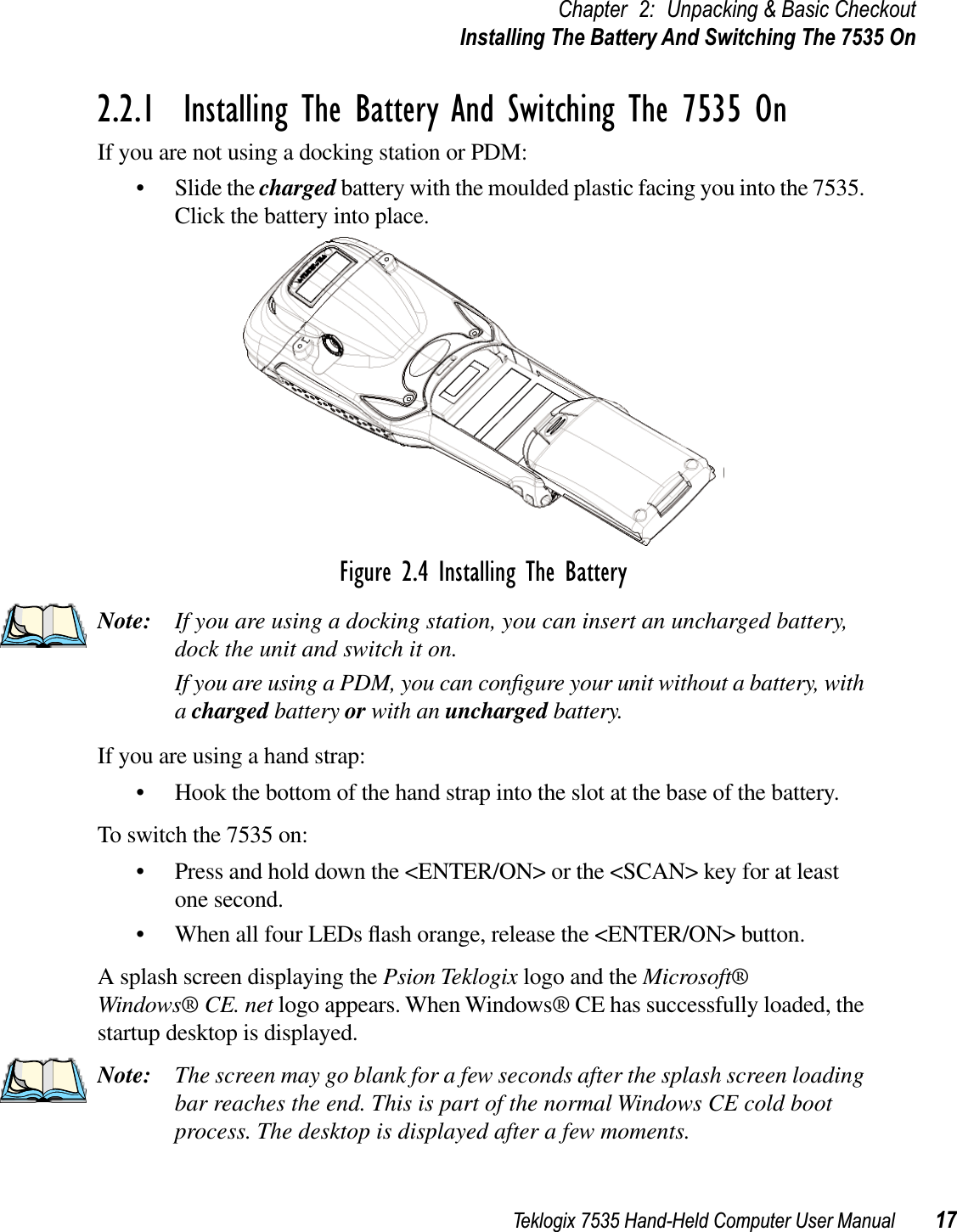
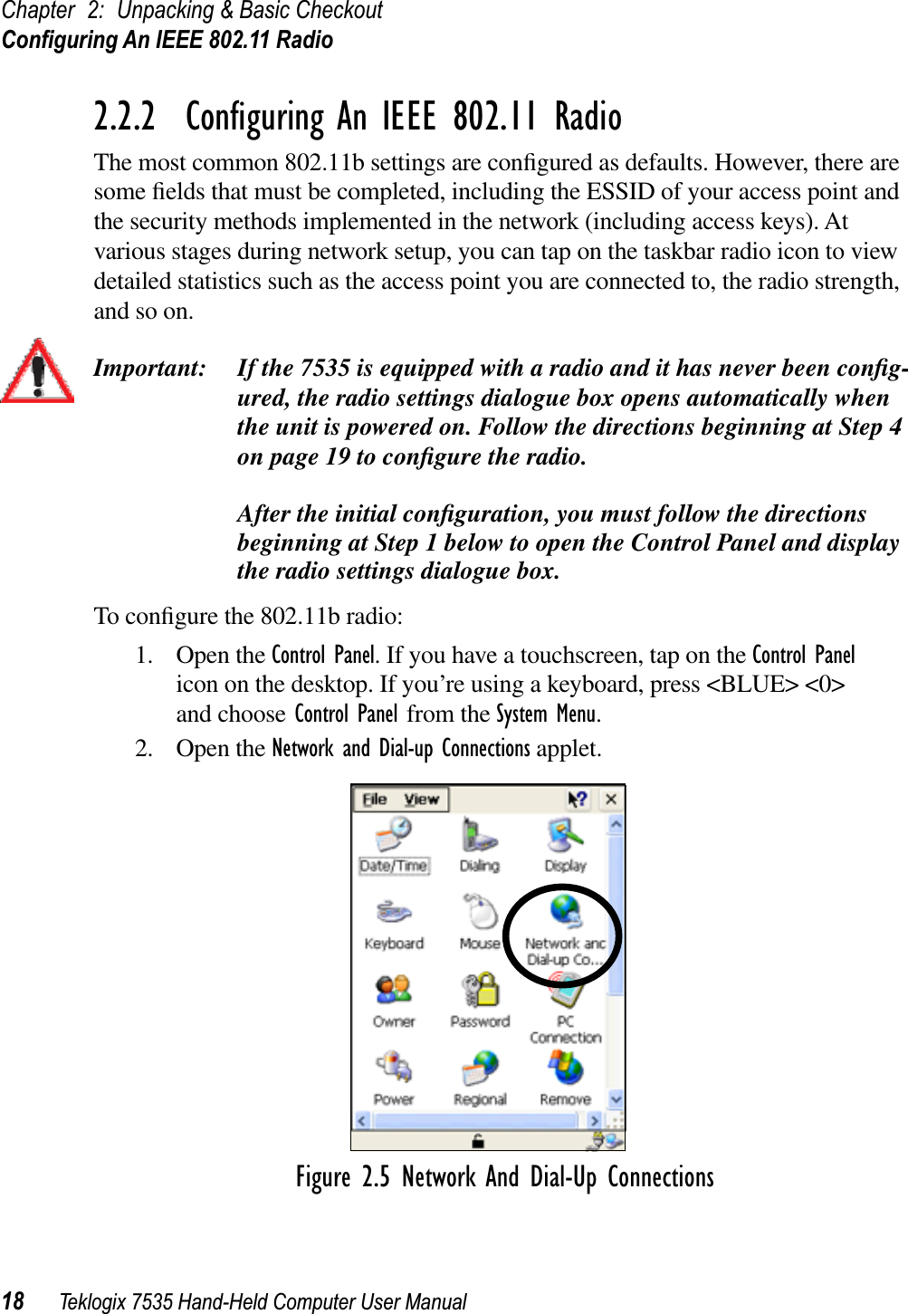
Psion WCF2011BE HANDHELD TERMINAL User Manual 7535May16
Psion Inc HANDHELD TERMINAL 7535May16
UserManual.wiki
>
Psion
>
WCF2011BE User Manual
USERS MANUAL
Navigation menu
Upload a User Manual
Namespaces
Wiki Guide
HTML
PDF
Info
Views
User Manual
Discussion / Help
Navigation


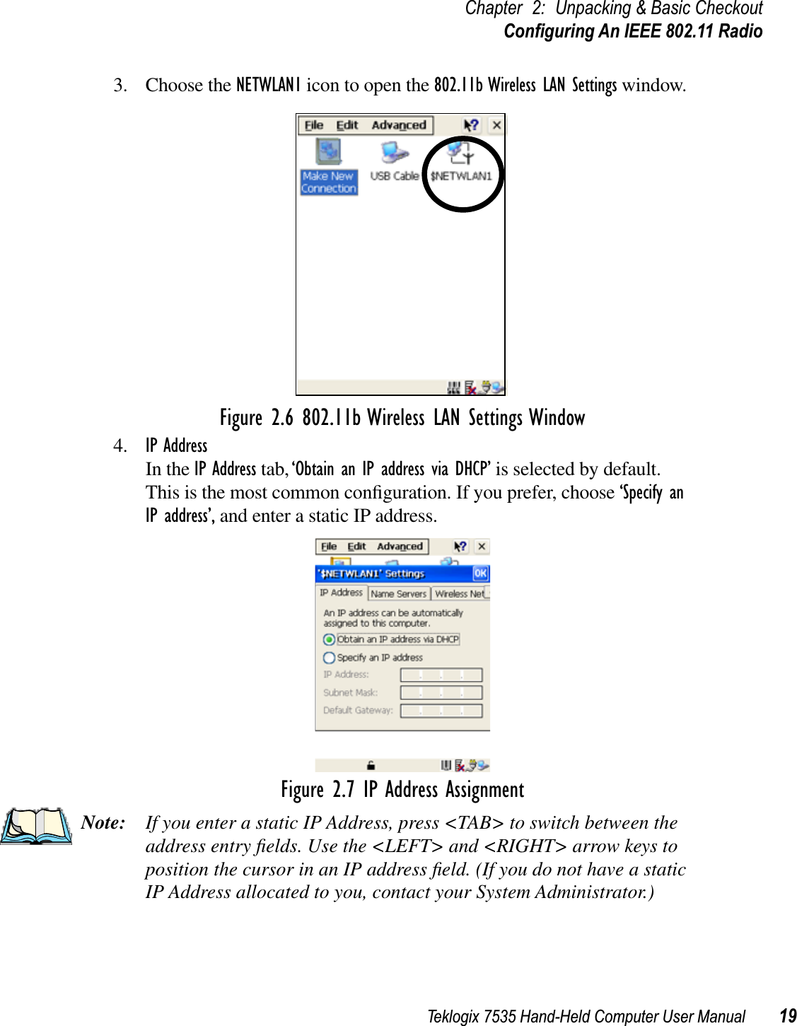
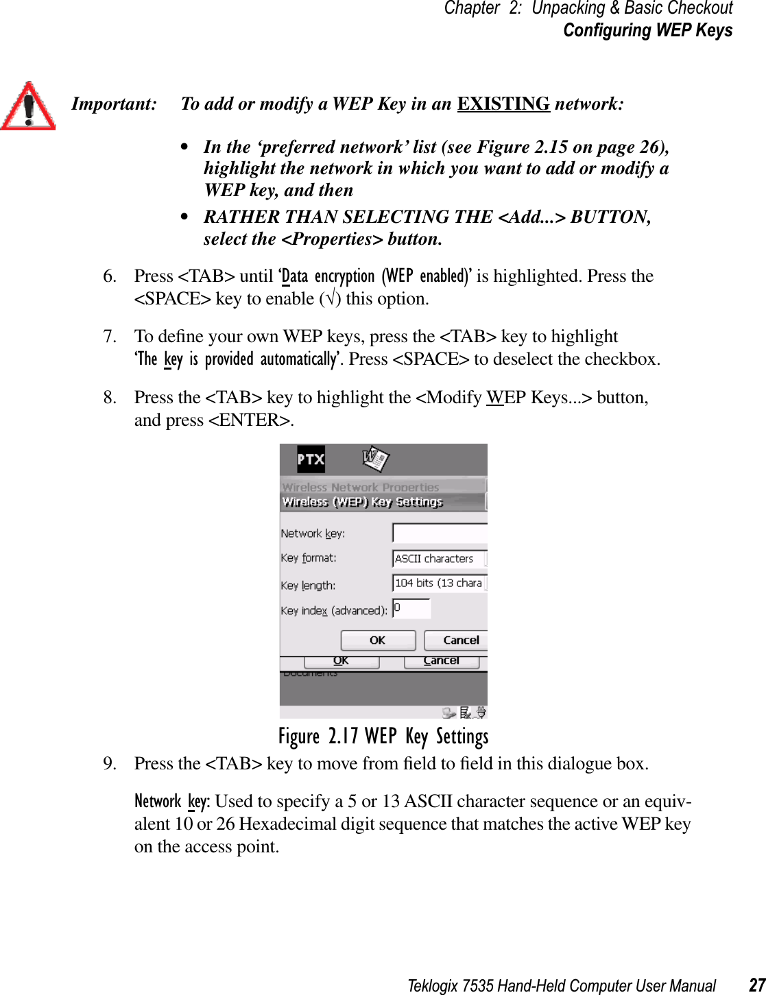
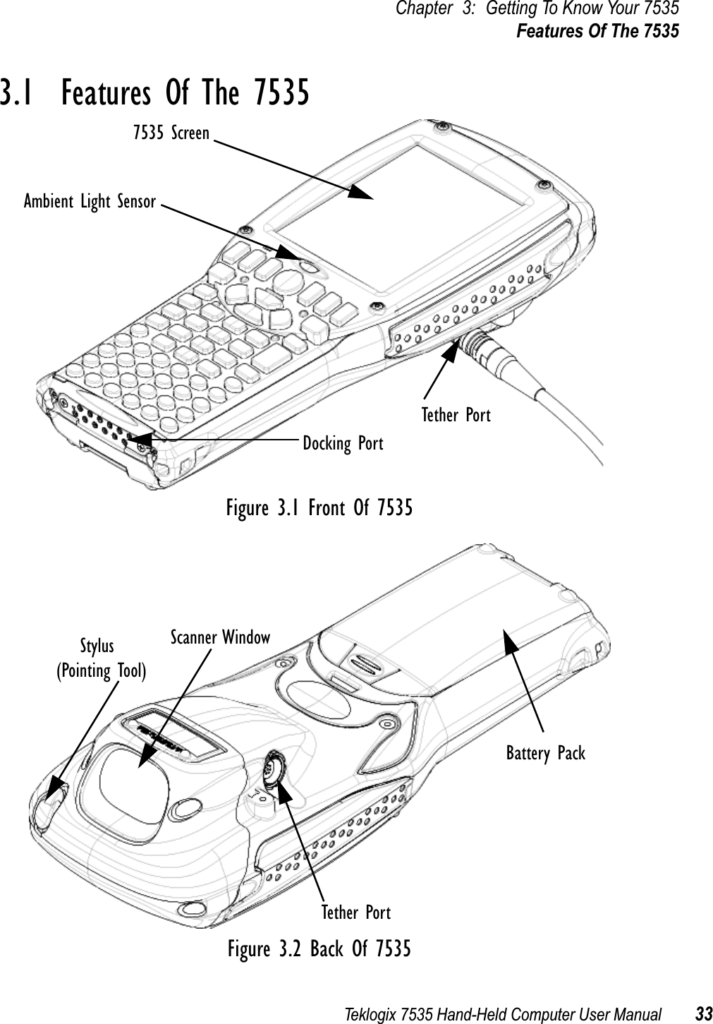
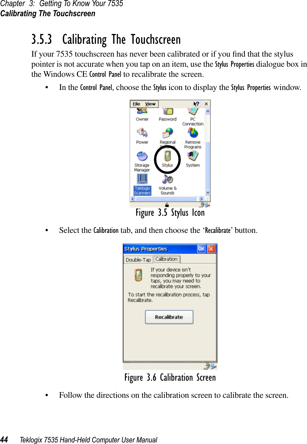
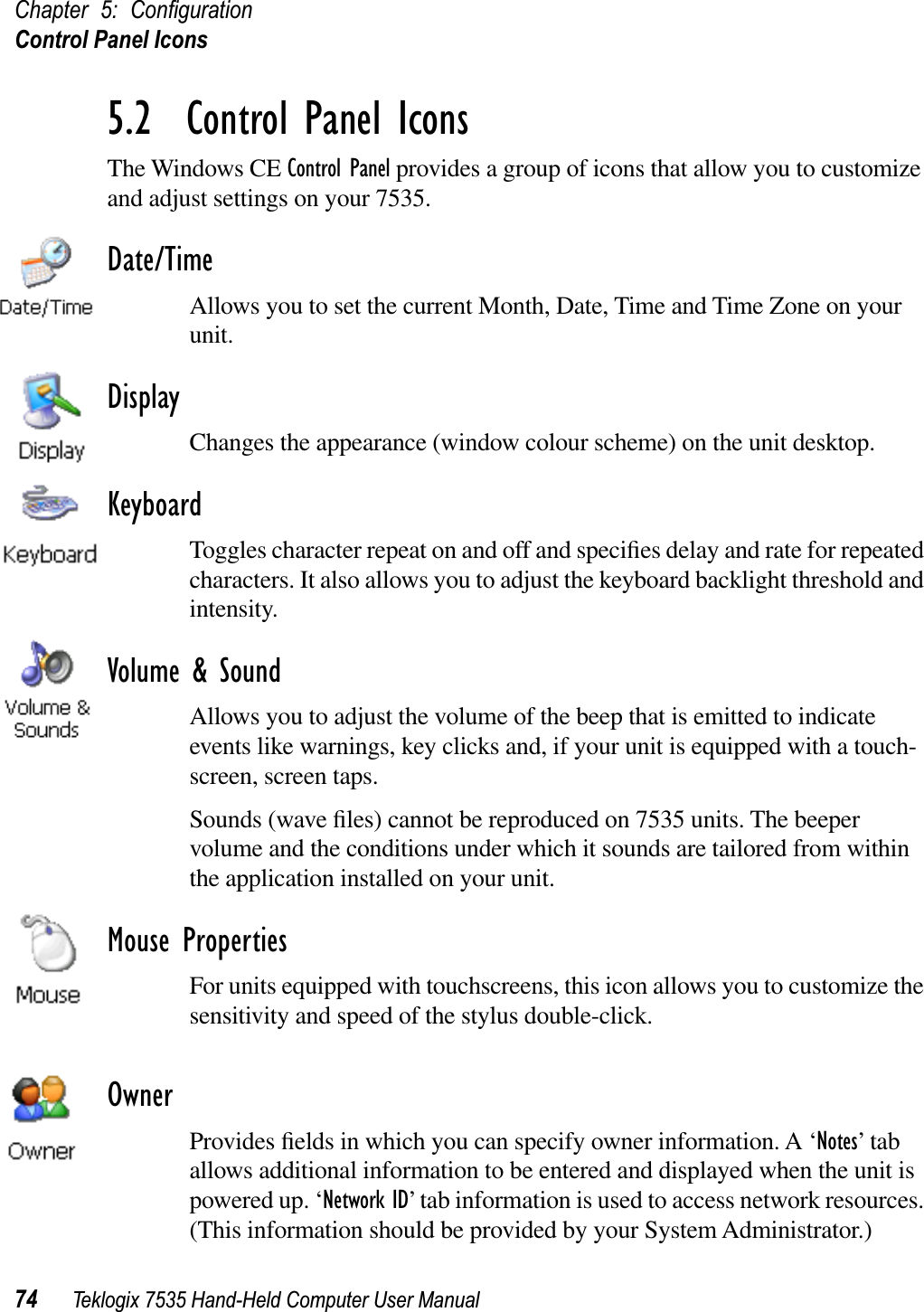
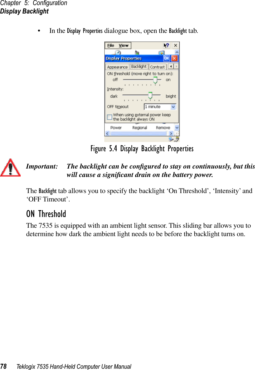
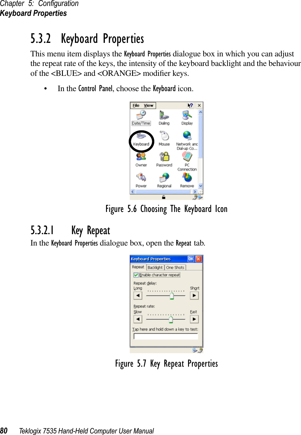
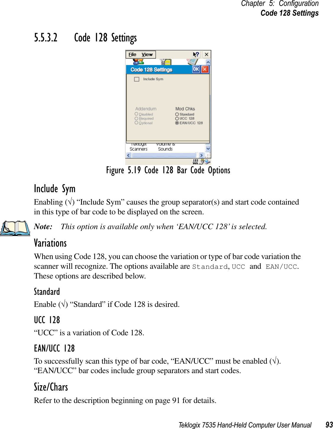
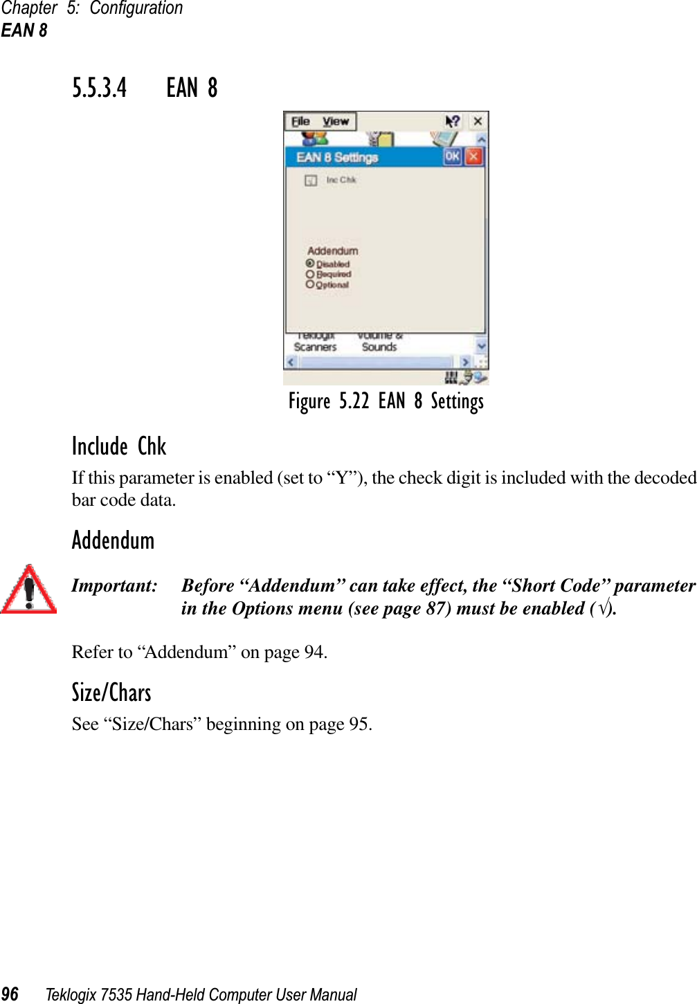
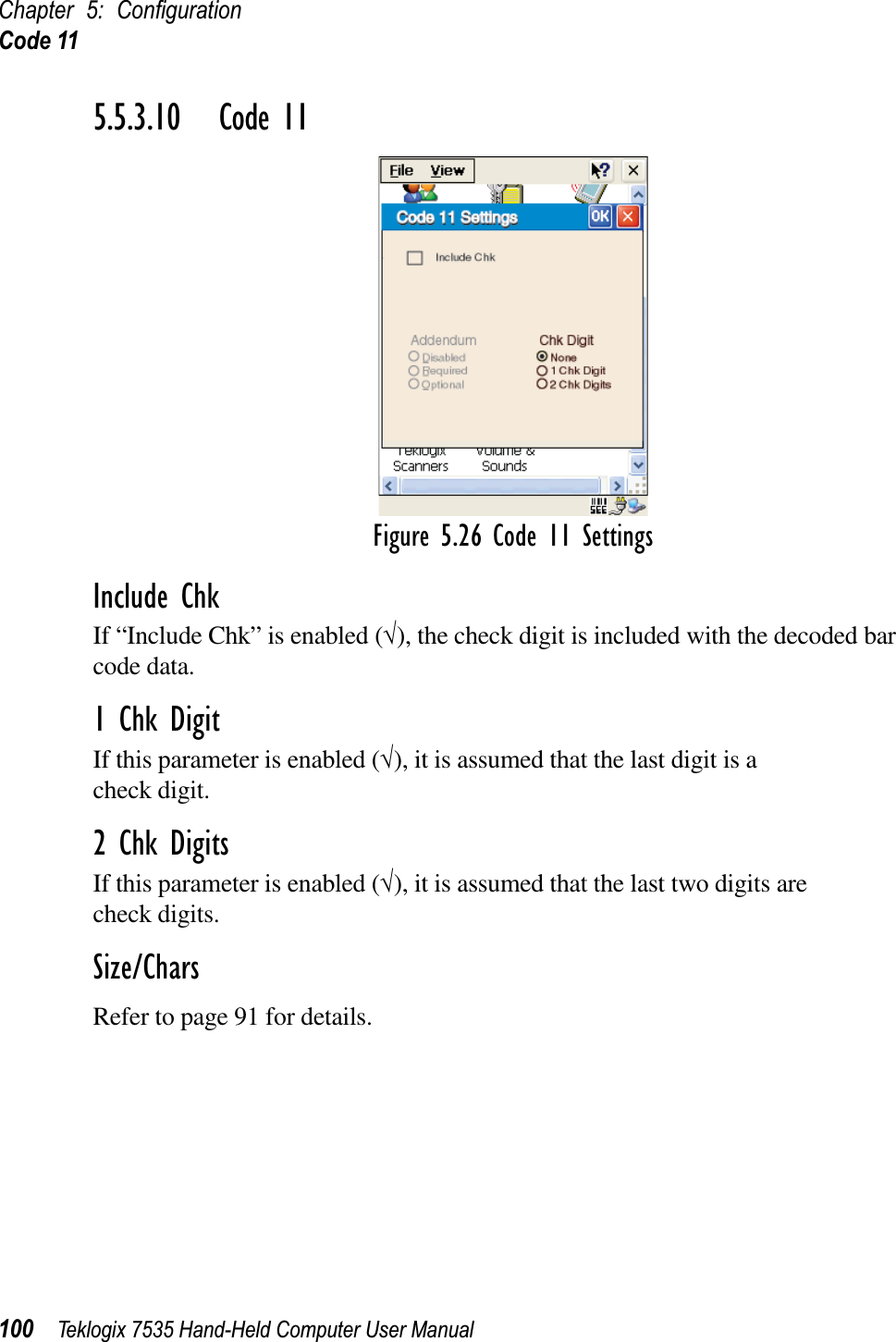
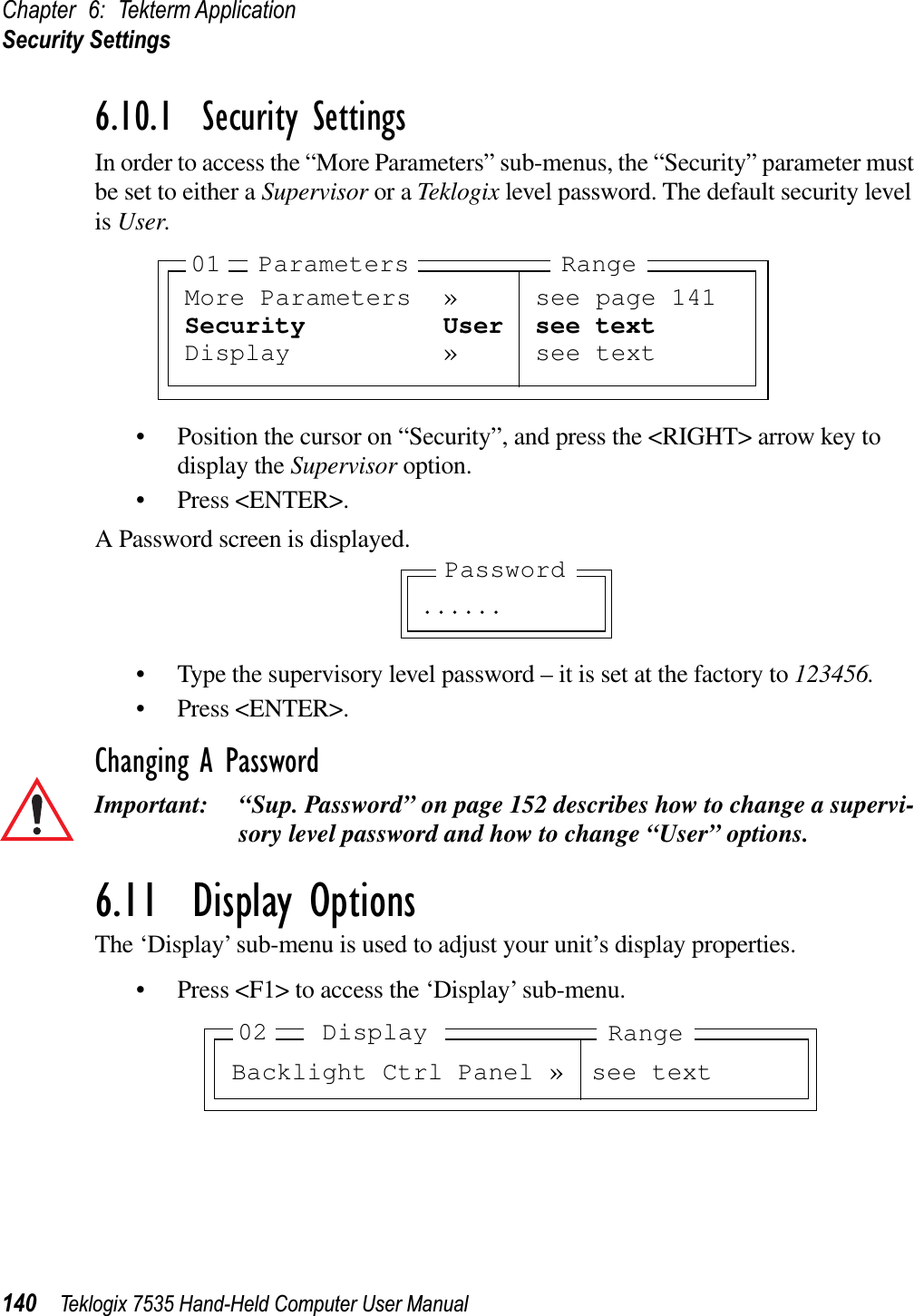
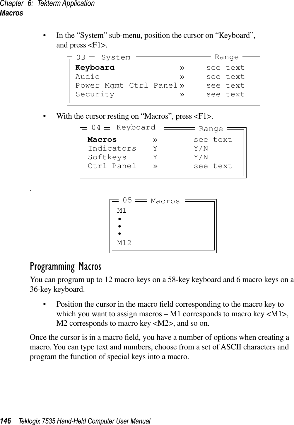
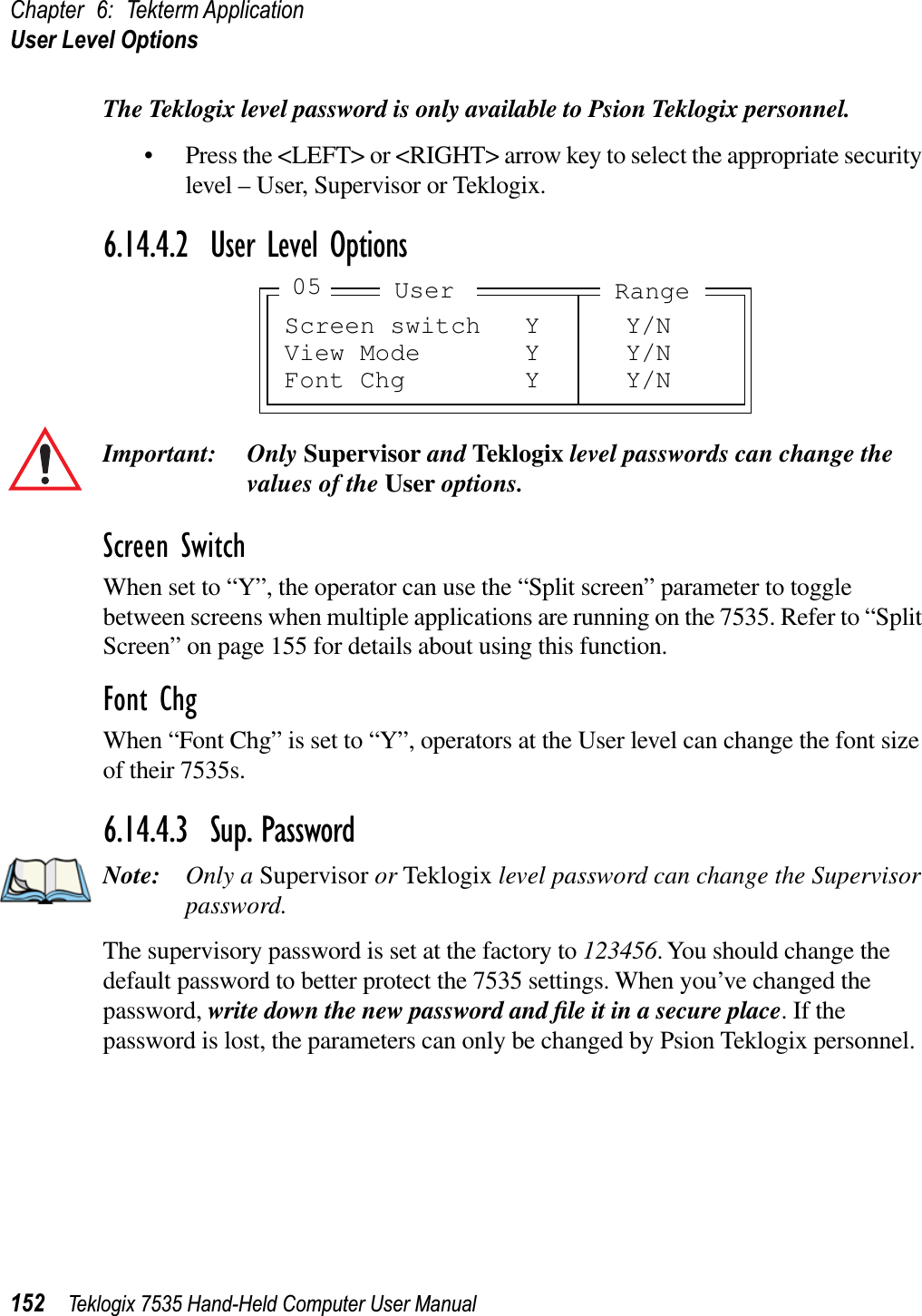
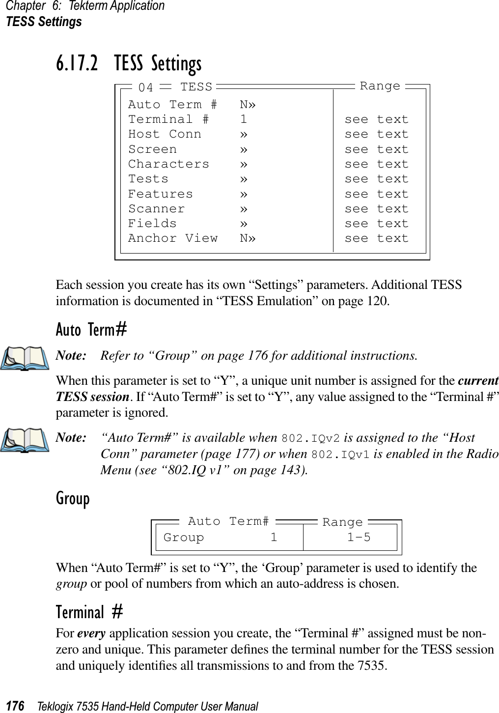
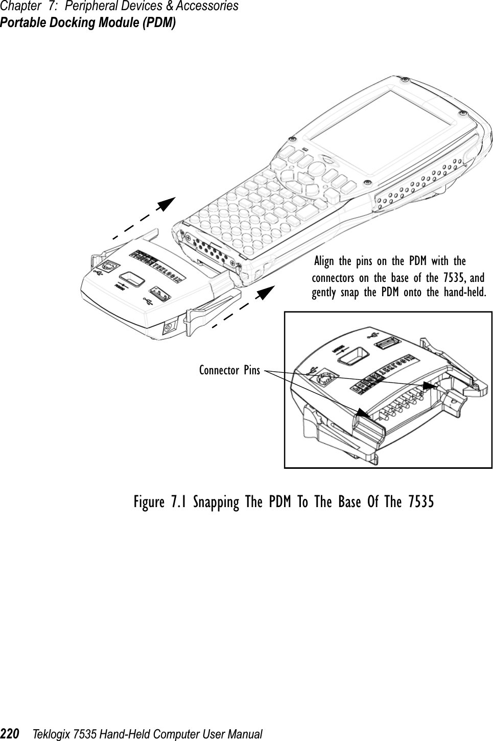
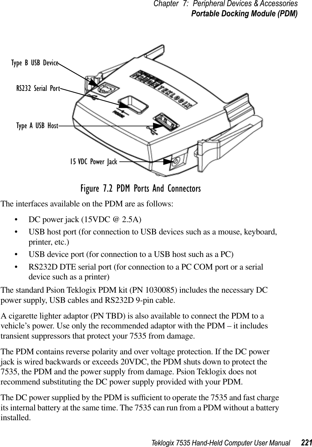
![Once WinCE is booted, the PC should indicate it has found a new USB storage device. (You will need the Windows 2000 operating system or later).[Final details TBD]To upload an application:• Drag the file onto the USB device folder. • Shut down the USB device on the PC before disconnecting the 7535. • Perform a cold reboot of the 7535 – hold down the <ENTER> and <BLUE> keys for at least a second.2.7 Calibrating The TouchscreenIf your 7535 is equipped with a touchscreen, it will need to be calibrated. Refer to “Calibrating The Touchscreen” on page 44 for details.2.8 Resetting The 7535 Hand-HeldNote: You do not need to reset your 7535 after configuring the radio.To reset the 7535:• Press and hold down the <BLUE> key and the <ENTER/ON> key simulta-neously for a minimum of six seconds.A reset results in a complete reboot of the unit. All RAM memory contents are lost. The contents of the flash memory and memory card are preserved.When the 7535 is reset, the screen displays the Psion Teklogix and Microsoft® Windows® CE.net splash screen before displaying the startup desktop.](https://usermanual.wiki/Psion/WCF2011BE/User-Guide-336229-Page-50.png)
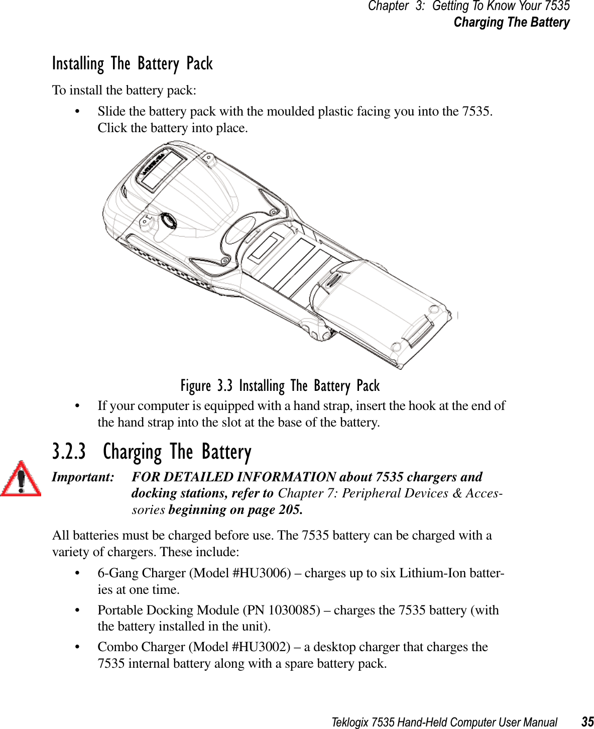
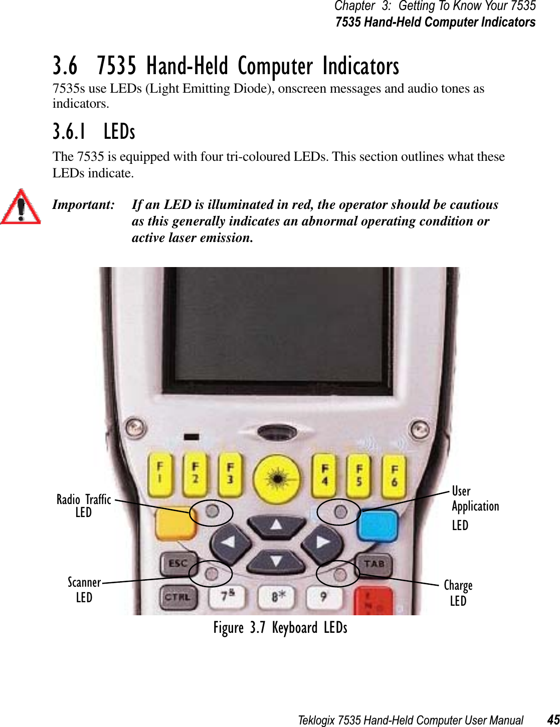


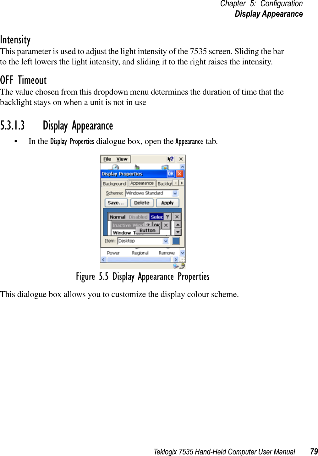
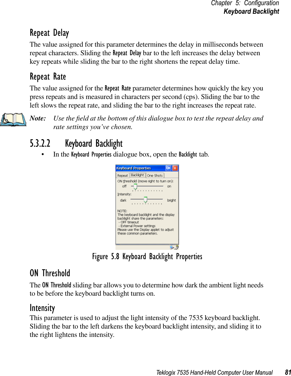
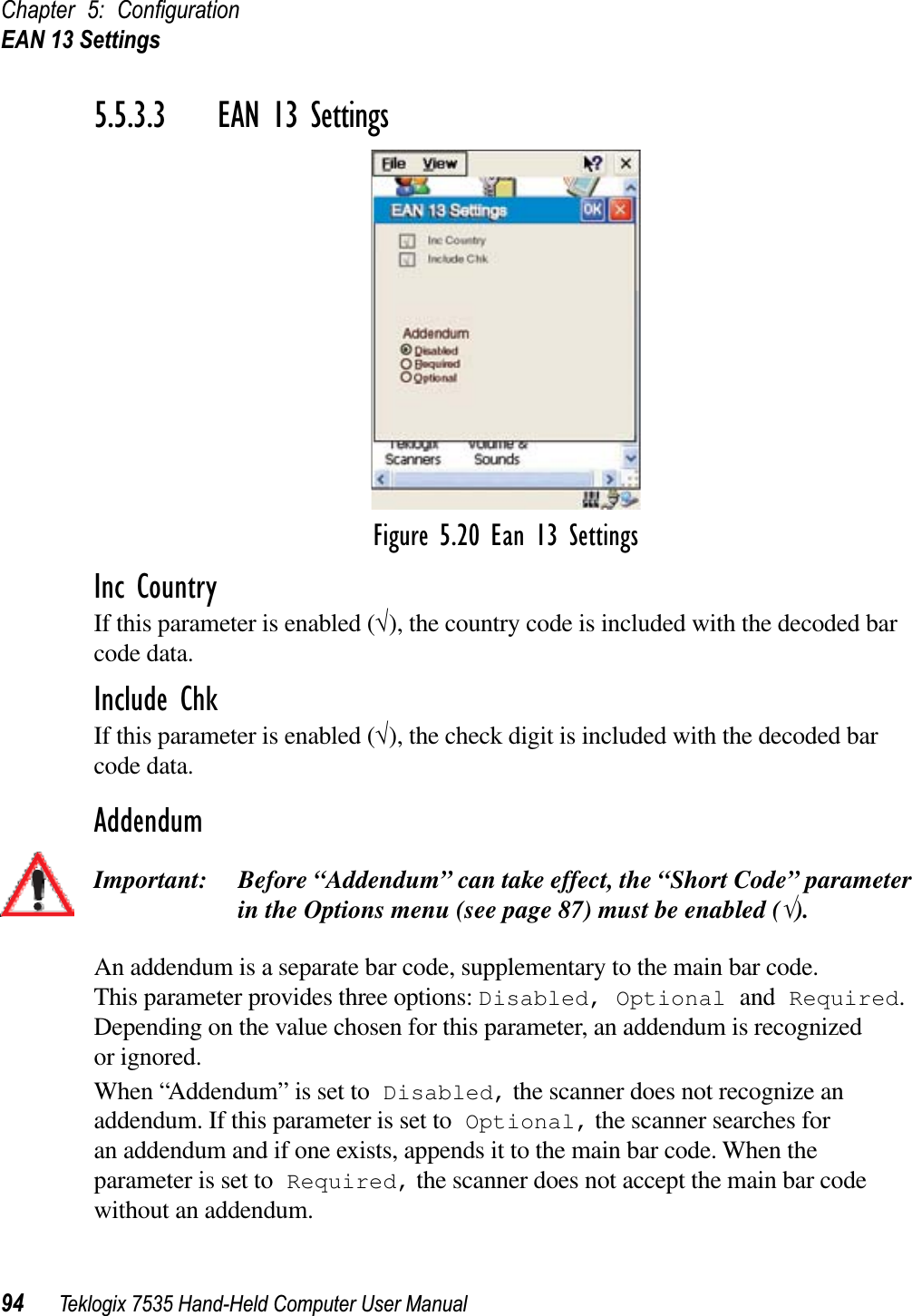
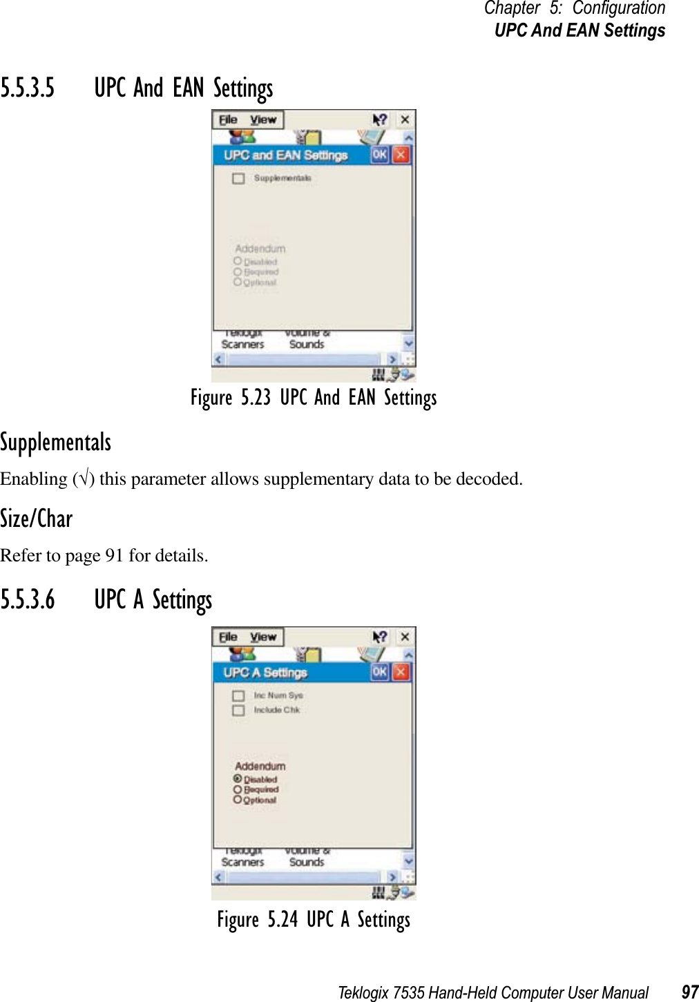

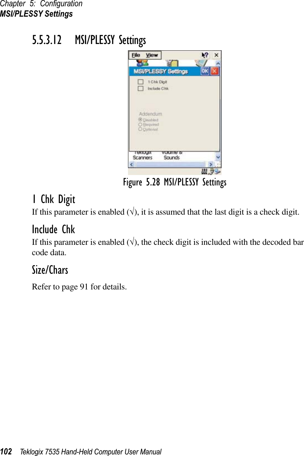
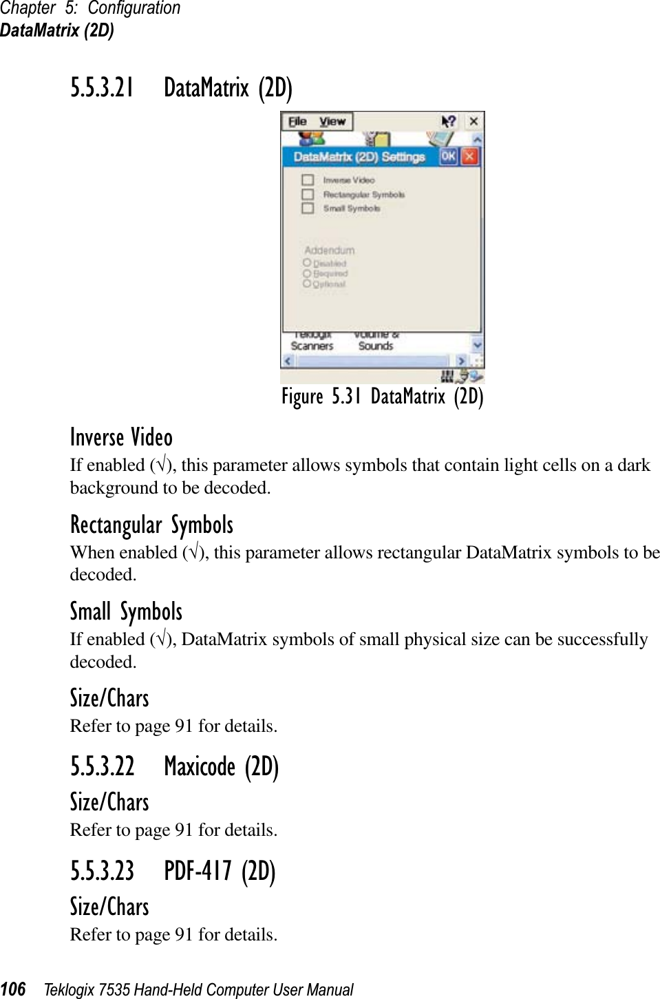
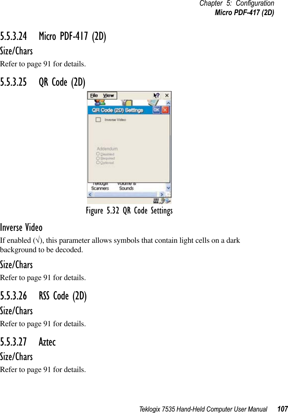
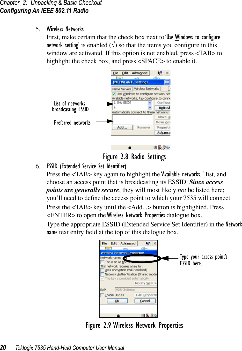
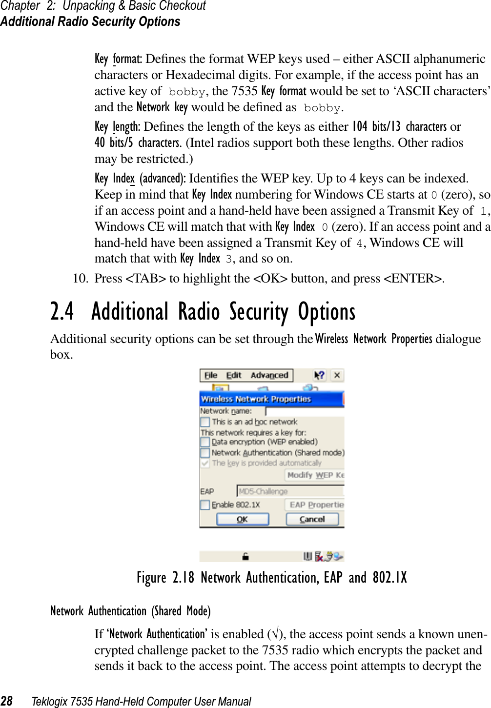
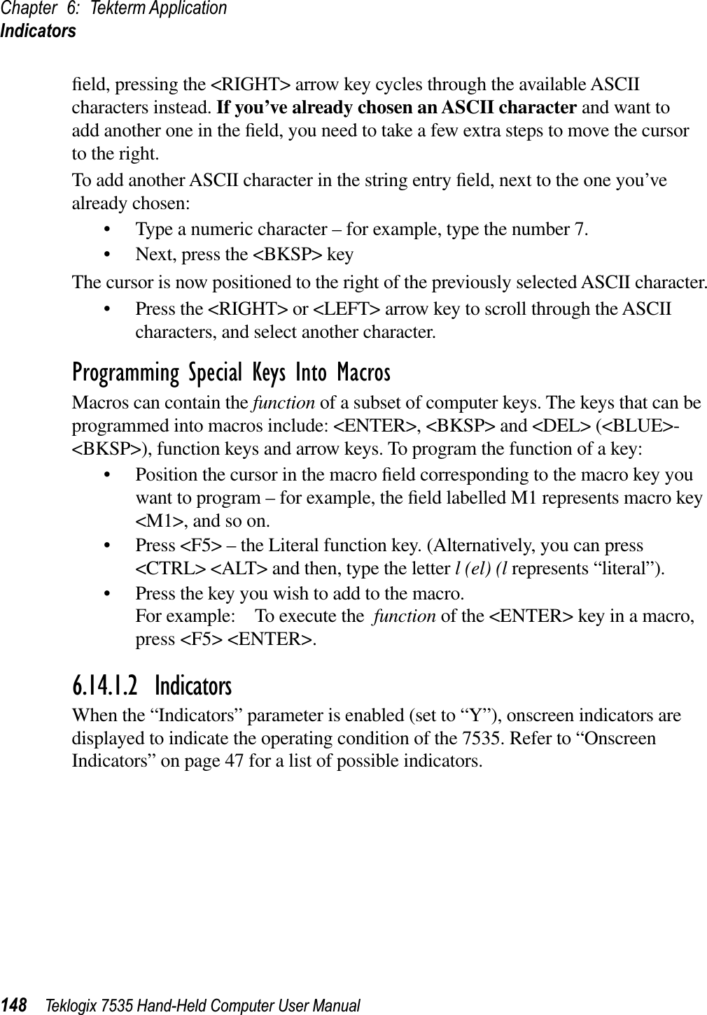
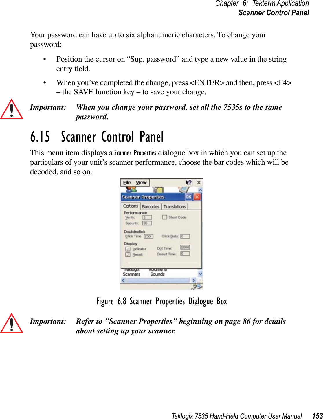
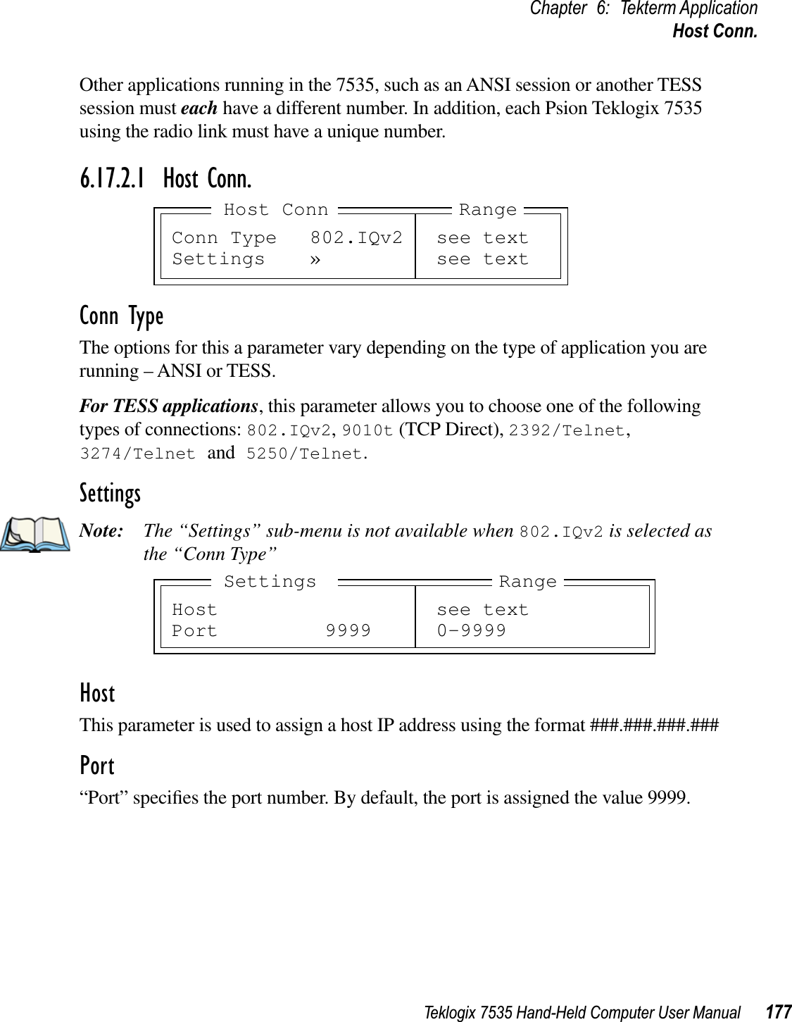
![Teklogix 7535 Hand-Held Computer User Manual 147Chapter 6: Tekterm ApplicationMacrosIn macros, the <UP> arrow, <DOWN> arrow, <ENTER> and <DEL> keys have the following functions:• Pressing the <UP> and <DOWN> arrow keys move the cursor between entry fields.• Pressing the <ENTER> key once moves the cursor to the first position in the entry field; pressing <ENTER> a second time completes the entry field, exits the sub-menu and returns the cursor to the “parent” or previous menu.• The <BKSP> key deletes the character to the left of the cursor.• The <DEL> key – <BLUE> <BKSP> – clears the entire field. If the last character in a field is deleted, the previous contents, if any, reappear.Entering Text In A String Entry FieldIn addition to using the fixed set of ASCII values assigned to this type of parameter, you can also type text in a string entry field.• Type the required text in the string entry field – including letters, numbers and symbols.• Press <ENTER> to save the text.Entering Unicode™ ValuesUnicode is a trademark of The Unicode Consortium. To enter a Unicode™ value:• Press and hold down the <ALT> key while typing a four digit decimal value that represents the Unicode™ character you want to display.• Release the <ALT> key.Choosing An ASCII CharacterImportant: Make sure the <CTRL>, <ALT> and <CAPS> keys are turned off!By pressing either the <RIGHT> or <LEFT> arrow key, you can cycle through a set of printable characters. The sample below is a set of ASCII characters accessible from within a macro field: ? ’ , < > [ ] ^ _ ` { | } ~ =• Press the <RIGHT> arrow to display the next character in this sequence, and the <LEFT> arrow to display the previous one.Adding Additional ASCII CharactersWhen you’ve chosen an ASCII character and want to add another one in the same field, the cursor must be moved to the right of the existing character. Normally, pressing the <RIGHT> arrow key moves the cursor to the right, but in a string entry](https://usermanual.wiki/Psion/WCF2011BE/User-Guide-336229-Page-167.png)
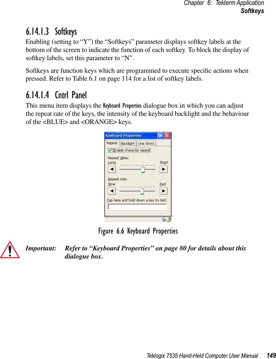

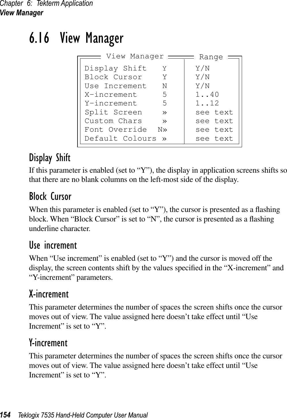
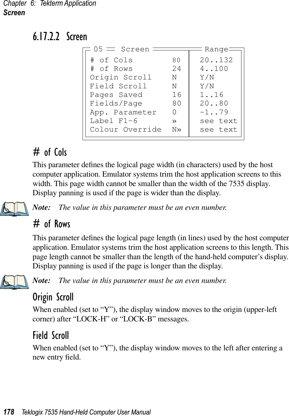
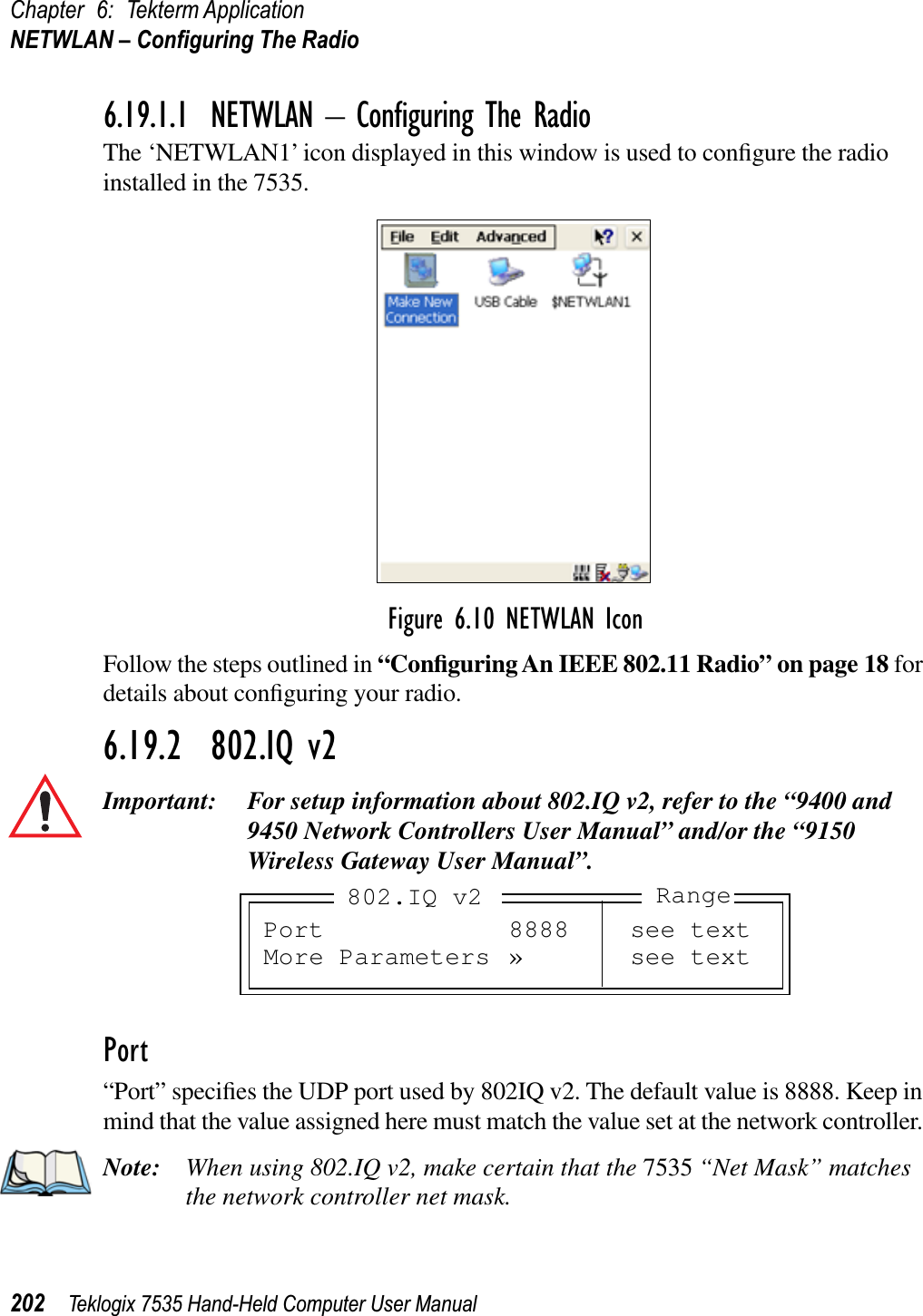


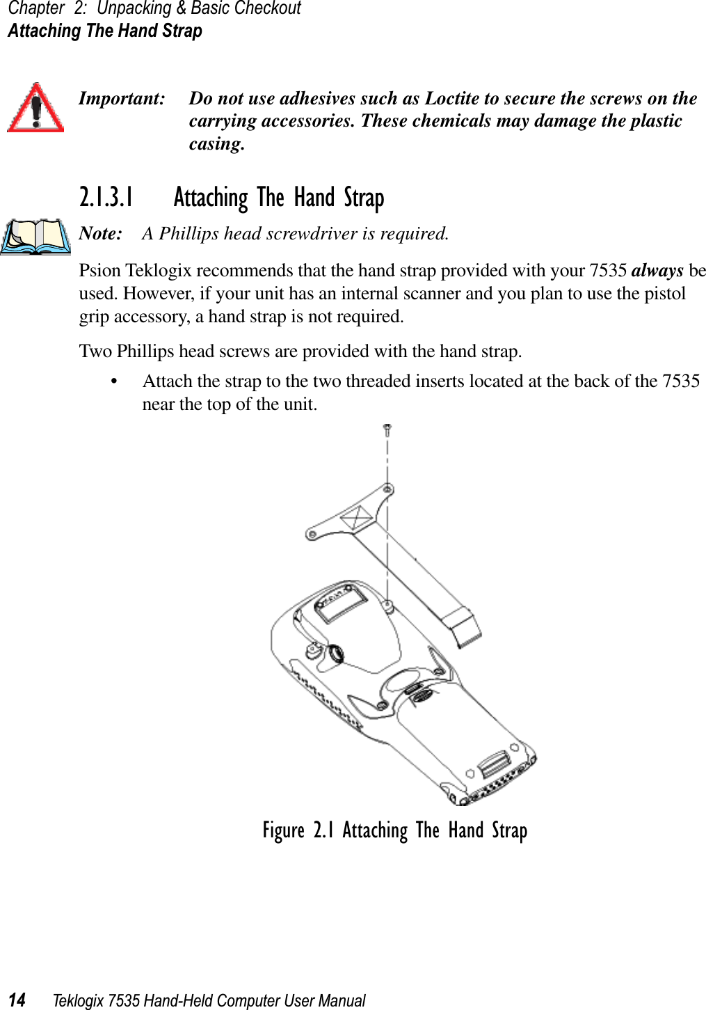
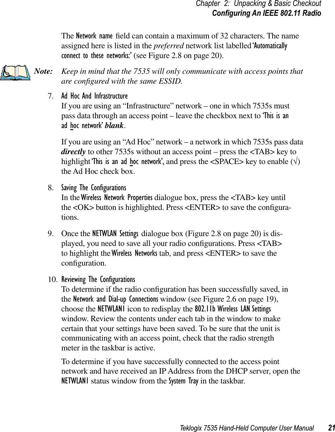
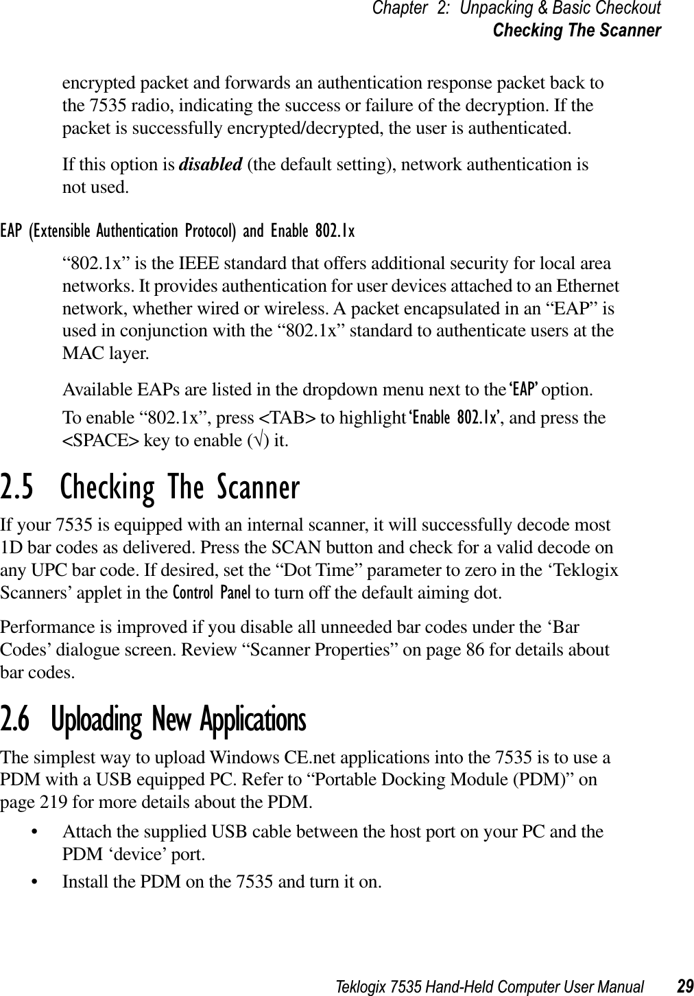
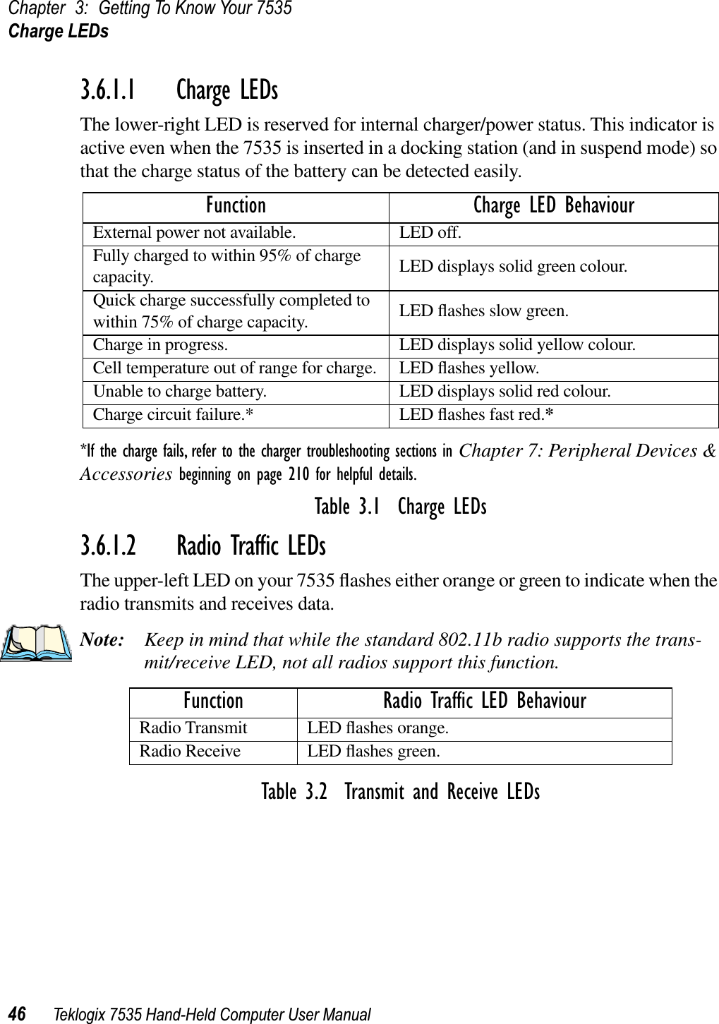
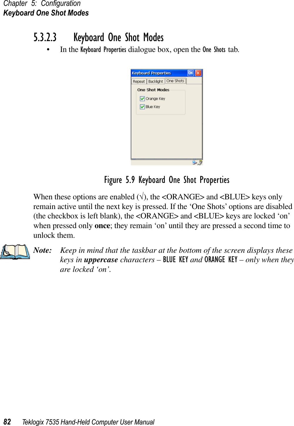
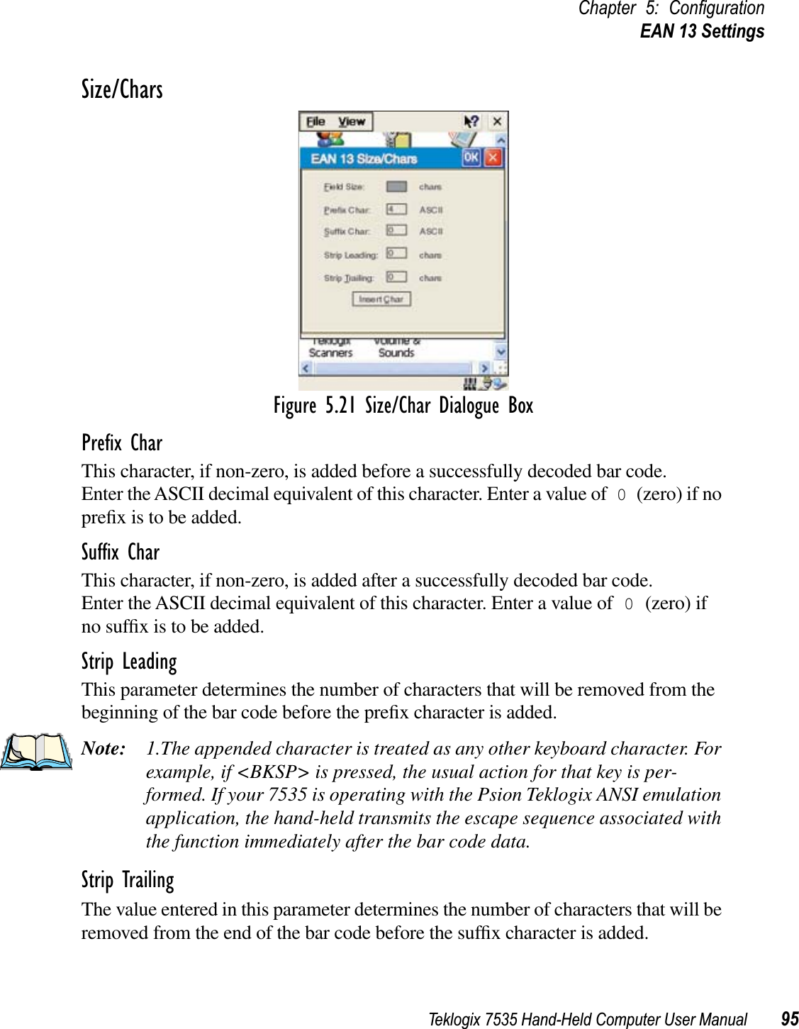
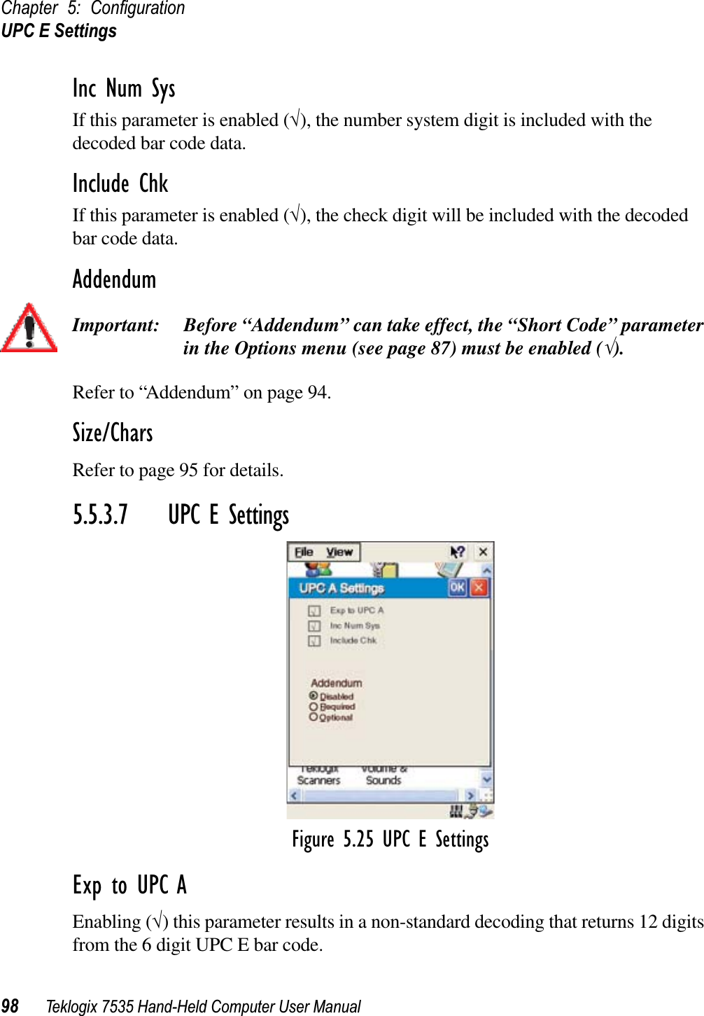
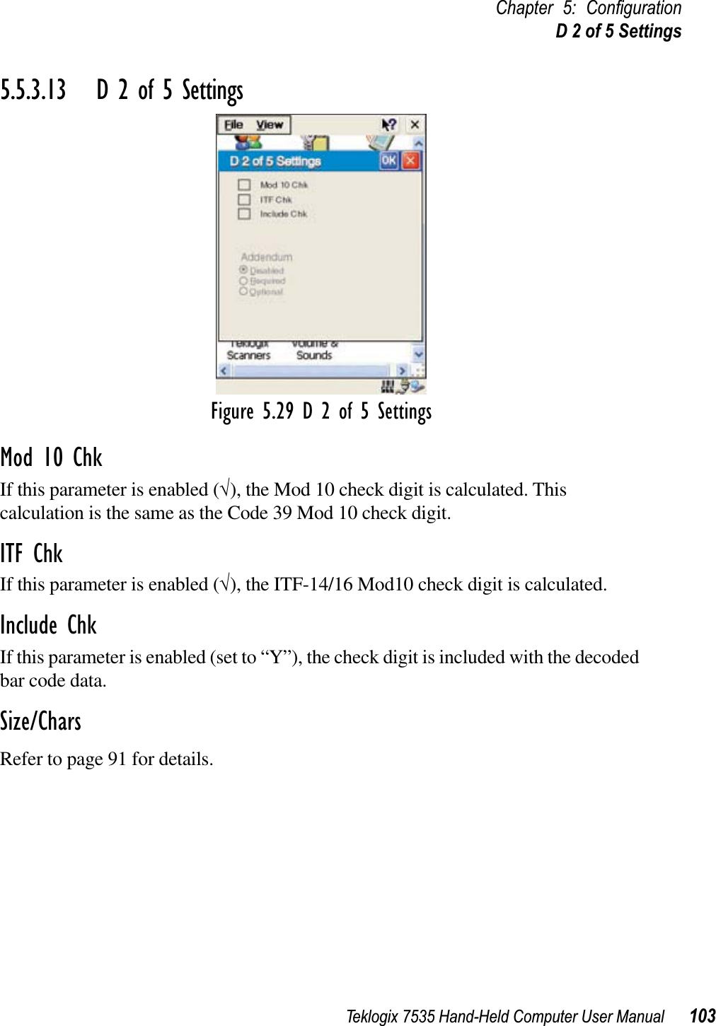
![Teklogix 7535 Hand-Held Computer User Manual 223Chapter 7: Peripheral Devices & AccessoriesMounting Recommendations7.11.1 Mounting RecommendationsWarning: Before mounting a picker cradle in a vehicle, there are a number of operator safety issues that require careful attention. An improp-erly mounted cradle may result in one or more of the following: operator injury, operator visibility obstruction, operator distraction and/or poor ease of egress for the operator. Psion Teklogix strongly recommends that you seek professional mounting advice from the vehicle manufacturer. Cable routing within a vehicle cab also requires careful consider-ation, especially for separately tethered scanners and other devices with loose cables. If you are unable to obtain suitable advice, contact Psion Teklogix for assistance (see Appendix A: Support Services And Worldwide Offices). Note also that for better protec-tion, the equipment should be mounted inside the vehicle roll cage.Pedestal mounts are recommended for all fixed mount locations because they offer optimal operator access. In addition, for safety reasons, only pedestal mounts with fully locking joints are recommended. Always adjust the pedestal for the optimum viewing angle, and securely tighten the hex and wing screws.The most effective way to mount the picker cradle is to use the four #8-32 threaded inserts on the rear of the unit. Bolts must not extend more than 10mm (3/8") into the cradle. All Psion Teklogix mounting hardware is compatible with this method. Under special circumstances, it may be necessary to mount bolts through the cradle into a plate. In this case, the cradle requires partial disassembly. To accommodate the surface loop of the connector cable, leave a 4" clearance at the bottom of the cradle. Leave a 7" clearance at the top of the cradle to allow easy removal of the 7535. Refer to the detailed assembly instructions that are packaged with the cradle for this application (PN TBD)7.11.1.1 Mounting TemplateThe picker cradle is shipped with detailed mounting instructions including a drill template. [Drawing TBD].](https://usermanual.wiki/Psion/WCF2011BE/User-Guide-336229-Page-243.png)