103131 2 Weg Variable Frequency Drive User Manual Users
136287 2 Weg Variable Frequency Drive Users Manual 136287_2_WEG Variable Frequency Drive Users Manual
User Manual: Pump 103131 2 Weg Variable Frequency Drive Users Manual
Open the PDF directly: View PDF ![]() .
.
Page Count: 211 [warning: Documents this large are best viewed by clicking the View PDF Link!]
- Summary
- QUICK PARAMETER REFERENCE, FAULT AND STATUS MESSAGES
- SAFETY NOTICES
- GENERAL INFORMATION
- INSTALLATION AND CONNECTION
- 3.1 MECHANICAL INSTALLATION
- 3.2 ELECTRICAL INSTALLATION
- 3.3 EUROPEAN EMC DIRECTIVE - REQUIREMENTS FOR CONFORMING INSTALLATIONS
- KEYPAD (HMI) OPERATION
- START-UP
- DETAILED PARAMETER DESCRIPTION
- DIAGNOSTICS AND TROUBLESHOOTING
- CFW-08 OPTIONS AND ACCESSORIES
- 8.1 HMI-CFW08-P
- 8.2 TCL-CFW08
- 8.3 HMI-CFW08-RP
- 8.4 MIP-CFW08-RP
- 8.5 CAB-RP-1 CAB-RP-2 CAB-RP-3 CAB-RP-5 CAB-RP-7.5 CAB-RP-10
- 8.6 HMI-CFW08-RS
- 8.7 MIS-CFW08-RS
- 8.8 CAB-RS-1 CAB-RS-2 CAB-RS-3 CAB-RS-5 CAB-RS-7.5 CAB-RS-10
- 8.9 KDC-24VR-CFW08
- 8.10 KDC-24V-CFW08
- 8.11 KCS-CFW08
- 8.12 KSD-CFW08
- 8.13 KRS-485-CFW08
- 8.14 KFB-CO-CFW08
- 8.15 KFB-DN-CFW08
- 8.16 KAC-120-CFW08 KAC-120-CFW08-N1M1 KAC-120-CFW08-N1M2
- 8.17 KMD-CFW08-M1
- 8.18 KFIX-CFW08-M1 KFIX-CFW08-M2
- 8.19 KN1-CFW08-M1 KN1-CFW08-M2
- 8.20 RFI FILTER
- 8.21 LINE REACTOR
- 8.22 LOAD REACTOR
- 8.23 DYNAMIC BRAKING
- 8.24 SERIAL COMMUNICATION
- 8.25 MODBUS-RTU
- 8.25.1 Introduction to Modbus-RTU Protocol
- 8.25.2 Operation of the CFW-08 in the Modbus-RTU Network
- 8.25.3 Detailed Function Description
- 8.25.3.1 Function 01 - Read Coils
- 8.25.3.2 Function 03 - Read Holding Register
- 8.25.3.3 Function 05 - Write Single Coil
- 8.25.3.4 Function 06 - Write Single Register
- 8.25.3.5 Function 15 - Write Multiple Coils
- 8.25.3.6 Function 16 - Write Multiple Registers
- 8.25.3.7 Function 43 - Read Device Identification
- 8.25.4 Modbus-RTU Communication Errors
- TECHNICAL SPECIFICATIONS
Motors | Energy | Automation | Coatings
Frequency Inverter
Convertidor de Frecuencia
Inversor de Freqüência
Frequenzumrichter
Variateur de Vitesse
Преодразователь частоты
Frequentie Regelaar
Frekvensomvandlare
CFW-08
User's Guide
Manual del Usuario
Manual do Usuário
Bedienungsanleitung
Manuel d'utilisation
Руководство пользователя
Gebruikers Handleiding
Användarinstruktioner

03/2009
FREQUENCY
INVERTER
MANUAL
ATTENTION!
It is very important to check if the
inverter software version is the
same as indicated above.
Series:
CFW-08
Software:
vers
ion 5.2
X
Language
:
English
Document
:
0899.5242 / 09

2
Summary of Revisions
The table below describes all revisions made tothis manual.
Revision
Description
Section
1
First Edition
-
2
Inclusion of the item 3.3 - European
Refer to item 3.3
EMC Directive - Requirements for
Conforming Installations
3
General Revision
-
4
External Parallel Keypad and
Refer to item 8.3
Fix Kit included and
and 8.18
General Revision
5
Description changed of the
Refer to item 8.5
Parallel Cable
for the External Parallel Keypad
Item 7.5 (Spare Part List) removed
Parameter P536 included
Refer to item 6.3.5
and General Revision
6
General Revision
-
7
Inclusion of new models (22 A, 28 A and
Refer to item 9.1
33 A/200-240 V; 24 A and 30 A/380-480 V)
Addition of new I/O functions
Refer to item 3.2.5
on the control board
Modification of circuit breakers table
Refer to item 3.2.3
Modification of chapter 3
(installation and connections)
Modification of parameters
Refer to item 4.2.4
incompatibility table
Addition of parameters P253,
Refer to item 6.3
P267 and P268
Addition of new functions at parameters
P235, P239, P295 and P404
Modification of factory default
Refer to item 6.3.3
value of parameter P248
Addition of error code E32
Refer to item 7.1
8
General Revision
Inclusion of items into the table of
Refer to item 4.2.4
parameters incompatibility
Change on the WEG part number
Refer to chapter 8
of the optional devices
Inclusion of the table containing the
Refer to item 3.1.3.1
airflow requirements for panel mounting
Inclusion of the following optionals:
Refer to chapter 8
KRS-485-CFW08, KFB-CO-CFW08,
KFB-DN-CFW08 and KAC-120-CFW08
Inclusion of the new versions
Refer to item 2.4
of the control board: A3 and A4
9
The Sleep function was added
Refer to chapter 6
(parameters P212, P213 and P535)
TheAnalog Input Dead Zonefunction
was added (P233)
The KDC-24VR-CFW08 and
Refer to items 8.9
KDC-24V-CFW08 option modules
and 8.10
were added
New EMC filters were added
Refer to item 3.3.4
Notes on the CFW-08 Nema 4X
Refer to chapter 2.4
and the 575 V lines were added
Modification of the gain equation
for the analog inputs
General revision
-

Summary
Quick Parameter Reference,
Fault and Status Messages
I Parameters
....................................................................
8
II Fault Messages
...........................................................
16
III Other Messages
...........................................................
16
CHAPTER 1
Safety Notices
1.1 Safety Notices in the Manual
.....................................
17
1.2 Safety Notices on the Product
...................................
17
1.3 Preliminary Recommendations
.................................
17
CHAPTER 2
General Information
2.1About this Manual
......................................................
19
2.2 Software Version
.......................................................
19
2.3About the CFW-08
....................................................
20
2.4 CFW-08 Identification
...............................................
24
2.5 Receiving and Storing
...............................................
27
CHAPTER 3
Installation and Connection
3.1 Mechanical Installation
..............................................
28
3.1.1 Environment
........................................................
28
3.1.2 Mounting Specifications
......................................
28
3.1.3
Positioning and Fixing
........................................
31
3.1.3.1 Panel Mounting
..........................................
32
3.1.3.2 Surface Mounting
.......................................
33
3.2
Electrical Installation
.................................................
33
3.2.1 Power / Grounding Terminals
..............................
33
3.2.2
Location of the PowerTerminals, Grounding
Terminals and Control Terminal Connections
......
35
3.2.3
Power/Grounding Wiring and Circuit Breakers
..
36
3.2.4 Power Connections
............................................
37
3.2.4.1
AC Input Connection
................................
39
3.2.4.2
Output Connections
..................................
40
3.2.4.3
Grounding Connections
............................
40
3.2.5
Signal and Control
Connections
.........................
42
3.2.5.1
Digital Inputs as LowLevelActive
(S1:1 to OFF)
...........................................
46
3.2.5.2
Digital Input as High LevelActive
(S1:1 to ON)
.............................................
47
3.2.6 Typical Terminal Connections
.............................
48
3.3
European EMC Directive - Requirements
for Conforming Installations
......................................
51
3.3.1 Installation
...........................................................
51

Summary
3.3.2 Emission and Immunity Levels Description
........
52
3.3.3 Inverter Models and Filters
..................................
54
3.3.4 EMC Filters Characteristics
...............................
57
CHAPTER 4
Keypad (HMI) Operation
4.1 Keypad (HMI) Description
.........................................
67
4.2 Use of the Keypad (HMI)
...........................................
68
4.2.1 Keypad Operation
..............................................
69
4.2.2 Inverter Status
.....................................................
70
4.2.3 Read-Only Parameters
.......................................
71
4.2.4 Parameter Viewing and Programming
...............
71
CHAPTER 5
Start-up
5.1 Pre-Power Checks
....................................................
74
5.2 Initial Power-up
..........................................................
74
5.3 Start-up
......................................................................
75
5.3.1
Start-up Operation via Keypad (HMI) -
Type of Control: Linear V/F (P202 = 0)
...............
76
5.3.2
Start-up Operation via Terminals -
Control Mode: Linear V/F (P202 = 0)
.................
77
5.3.3
Start-up Operation via Keypad -
Control Mode: Vector (P202 = 2)
........................
78
CHAPTER 6
Detailed Parameter Description
6.1 Symbols ...
.................................................................
83
6.2 Introduction
................................................................
83
6.2.1 Control Modes (V/F and Vector)
.........................
83
6.2.2 V/F Control
.........................................................
83
6.2.3 Vector Control (VVC)
..........................................
84
6.2.4 Frequency Reference Sources
...........................
85
6.2.5
Commands
.........................................................
88
6.2.6 Local/Remote Operation Modes
........................
88
6.3 Parameter Listing
......................................................
89
6.3.1
Access and Read-only Parameters -
P000 to P099
.....................................................
90
6.3.2 Regulation Parameters - P100 to P199
.............
92
6.3.3 Configuration Parameters - P200 to P398
.......
102
6.3.4 Motor Parameters - P399 to P499
...................
128
6.3.5 Special Function Parameters - P500 to P599
..
131
6.3.5.1 Introduction
..............................................
131
6.3.5.2 Description
..............................................
131
6.3.5.3 PID Start-up Guide
...................................
134

Summary
CHAPTER 7
Diagnostics and Troubleshooting
7.1 Faults and Possible Causes
...................................
141
7.2 Troubleshooting
.......................................................
144
7.3 Contacting WEG
.....................................................
145
7.4 Preventive Maintenance
..........................................
145
7.4.1 Cleaning Instructions
.........................................
146
CHAPTER 8
CFW-08 Options and Accessories
8.1 HMI-CFW08-P
........................................................
149
8.1.1 Instructions forInsertion and Removing of
the HMI-CFW08-P
............................................
149
8.2 TCL-CFW08
...........................................................
149
8.3 HMI-CFW08-RP
......................................................
150
8.3.1 HMI-CFW08-RP Installation
..............................
150
8.4 MIP-CFW08-RP
......................................................
151
8.5 CAB-RP-1, CAB-RP-2, CAB-RP-3, CAB-RP-5,
CAB-RP-7.5, CAB-RP-10
......................................
151
8.6 HMI-CFW08-RS
......................................................
151
8.6.1 HMI-CFW08-RS Installation
..............................
152
8.6.2 HMI-CFW08-RS Start-up
..................................
152
8.6.3 Keypad Copy Function
.....................................
153
8.7 MIS-CFW08-RS
......................................................
153
8.8 CAB-RS-1, CAB-RS-2, CAB-RS-3, CAB-RS-5,
CAB-RS-7.5, CAB-RS-10
......................................
153
8.9 KDC-24VR-CFW08
................................................
154
8.10 KDC-24V-CFW08
.................................................
155
8.11 KCS-CFW08
.........................................................
156
8.11.1
Instructions for KCS-CFW08
Insertion and Removal
.....................................
157
8.12 KSD-CFW08
........................................................
157
8.13 KRS-485-CFW08
.................................................
158
8.14 KFB-CO-CFW08
..................................................
159
8.15 KFB-DN-CFW08
..................................................
160
8.16 KAC-120-CFW08, KAC-120-CFW08-N1M1
KAC-120-CFW08-N1M2
......................................
162
8.17 KMD-CFW08-M1
..................................................
163
8.18 KFIX-CFW08-M1, KFIX-CFW08-M2
....................
164
8.19 KN1-CFW08-M1, KN1-CFW08-M2
......................
165
8.20 RFI Filter
...............................................................
166
8.21 Line Reactor
..........................................................
167
8.21.1 Application Criteria
.......................................
167
8.22 Load Reactor
........................................................
170
8.23 Dynamic Braking
...................................................
171
8.23.1 Resistor Sizing
..............................................
171
8.23.2 Installation
.....................................................
172
8.24 Serial Communication
...........................................
173

Summary
8.24.1 Introduction
....................................................
173
8.24.2 RS-485 and RS-232 Interfaces Description
.
174
8.24.2.1 RS-485
..............................................
175
8.24.2.2 RS-232
..............................................
176
8.24.3 Definitions
.....................................................
176
8.24.3.1 Used Terms
.......................................
176
8.24.3.2 Parameter/Variables Resolution
........
177
8.24.3.3 Character Format
..............................
177
8.24.3.4 Protocol
.............................................
177
8.24.3.5 Execution and Message Test
.............
180
8.24.3.6 Message Sequence
..........................
180
8.24.3.7 Variable Code
...................................
180
8.24.4 Message Examples
......................................
181
8.24.5 Variables and Errors of the Serial
Communication
............................................
181
8.24.5.1 Basic Variables
.................................
181
8.24.5.2 Message Examples with Basic
Variables
............................................
184
8.24.5.3 Parameters Related to the Serial
Communication
...................................
185
8.24.5.4 Errors Related to the Serial
Communication
.................................
186
8.24.6 Time for Read/Write of Messages
................
186
8.24.7 Physical Connection RS-232 and RS-485
....
187
8.25 Modbus-RTU
.........................................................
188
8.25.1 Introduction to Modbus-RTU Protocol
...........
188
8.25.1.1 Transmission Modes
.........................
188
8.25.1.2 Message Structure in RTU Mode
......
188
8.25.2 Operation of the CFW-08 in the
Modbus-RTU Network
..................................
191
8.25.2.1 RS-232 and RS-485 Interface
Description
.......................................
191
8.25.2.2 Inverter Configuration in the
Modbus-RTU Network
.....................
191
8.25.2.3Access to the Inverter Data
...............
192
8.25.3 Detailed Function Description
......................
195
8.25.3.1 Function 01 - Read Coils
..................
195
8.25.3.2 Function 03 - Read Holding Register
196
8.25.3.3 Function 05 - Write Single Coil
.........
197
8.25.3.4 Function 06 - Write Single Register
..
198
8.25.3.5 Function 15 - Write Multiple Coils
......
198
8.25.3.6 Function 16 - Write Multiple Registers
199
8.25.3.7 Function 43 - Read Device
Identification
.....................................
200
8.25.4 Modbus-RTU Communication Errors
............
202
8.25.4.1 Error Messages
...............................
203

Summary
CHAPTER 9
Technical Specifications
9.1
Power Data
..............................................................
204
9.1.1 200-240 V Power Supply
..................................
204
9.1.2 380-480 V Power Supply
..................................
205
9.2 Electronics/General Data
........................................
208
9.3 WEG Standard IV-Pole Motor Data
.........................
209

8
CFW-08 - QUICK PARAMETER REFERENCE
Software: V5.2X
Application:
Model:
Serial Number:
Responsible:
Date: / / .
I. Parameters
QUICK PARAMETER REFERENCE, FAULT AND STATUS MESSAGES
Parameter
Function
Adjustable Range
Factory
Unit
User
Page
Setting
Setting
P000
Parameter Access
0 to 4 = Read
0
-
90
5 = Alteration
6 to 999 = Read
READ ONL
Y
P
ARAMETERS -
P002 to P099
P002
Frequency Proportional Value
0 to 6553
-
-
90
(P208xP005)
P003
Motor Output Current
0 to 1.5xI
nom
-
A
90
P004
DC Link Voltage
0 to 862
-
V
90
P005
Motor Output Frequency
0.00 to 300.0
-
Hz
90
P007
Motor Output Voltage
0 to 600
-
V
90
P008
Heatsink Temperature
25 to 110
-
°C
91
P009
(1)
Motor Torque
0.0 to 150.0
-
%
91
P014
Last Fault
00 to 41
-
-
91
P023
Software Version
x . y z
-
-
91
P040
PID Process Variable
0 to 6553
-
-
91
(Value % x P528)
REGULA
TION PARAMETERS -
P100 to P199
Ramps
P100
Acceleration Time
0.1 to 999
5.0
s
92
P101
Deceleration Time
0.1 to 999
10.0
s
92
P102
Ramp 2 Acceleration Time
0.1 to 999
5.0
s
92
P103
Ramp 2 Deceleration Time
0.1 to 999
10.0
s
92
P104
S Ramp
0 = Inactive
0
-
92
1 = 50 %
2 = 100 %
Frequency Reference
P120
Digital Reference Backup
0 = Inactive
1
-
93
1 = Active
2 = Backup by P121
P121
Keypad Reference
P133 to P134
3.00
Hz
93
P122
JOG Speed Reference
0.00 to P134
5.00
Hz
94
P124
Multispeed Reference 1
P133 to P134
3.00
Hz
94
P125
Multispeed Reference 2
P133 to P134
10.00
Hz
94
P126
Multispeed Reference 3
P133 to P134
20.00
Hz
94
P127
Multispeed Reference 4
P133 to P134
30.00
Hz
95
P128
Multispeed Reference 5
P133 to P134
40.00
Hz
95
P129
Multispeed Reference 6
P133 to P134
50.00
Hz
95
P130
Multispeed Reference 7
P133 to P134
60.00
Hz
95
P131
Multispeed Reference 8
P133 to P134
66.00
Hz
95

9
CFW-08 - QUICK PARAMETER REFERENCE
Parameter
Function
Adjustable Range
Factory
Unit
User
Page
Setting
Setting
(*)
The factory default of parameter P136 depends on the inverter model as follows:
- models 1.6-2.6-4.0-7.0 A/200-240 V and 1.0-1.6-2.6-4.0 A/380-480 V: P136 = 5.0 %;
- models 7.3-10-16 A/200-240 V and 2.7-4.3-6.5-10 A/380-480 V: P136 = 2.0 %;
- models 22-28-33 A/200-240 V and 13-16-24-30 A/380-480 V: P136 = 1.0 %.
Speed Limits
P133
Minimum Frequency (F
min
)
0.00 to P134
3.00
Hz
95
P134
Maximum Frequency (F
max
)
P133 to 300.0
66.00
Hz
96
V/F Control
P136
(2) (*)
Manual Torque Boost
0.0 to 30.0
5.0 or
%
96
(IxR Compensation)
2.0 or
1.0
(*)
P137
(2)
Automatic Torque Boost
0.00 to 1.00
0.00
-
97
(Automatic IxR Compensation)
P138
(2)
Slip Compensation
0.0 to 10.0
0.0
%
97
P142
(2) (3)
Maximum Output Voltage
0 to 100
100
%
98
P145
(2) (3)
Field Weakening
P133 to P134
50.00 Hz or
Hz
98
Frequency (F
nom
)
60.00 Hz
depending
on the
market
DC Link Voltage Regulation
P151
DC Link Voltage Regulation
200 V models: 325 to 410
380
V
99
Level
400 V models: 564 to 820
780
Overload Current
P156
Motor Overload Current
0.2xI
nom
to 1.3xI
nom
1.2xP401
A
100
Current Limitation
P169
Maximum Output Current
0.2xI
nom
to 2.0xI
nom
1.5xP295
A
101
Flux Control
P178
(1)
Rated Flux
50.0 to 150
100
%
101
CONFIGURA
TION PARAMETERS - P200
to
P398
Generic Parameters
P202
(3)
Control Mode
0 = Linear V/F Control
0
-
102
(Scalar)
1 = Quadratic V/F Control
(Scalar)
2 = S
ensorless Vector Control
P203
(3)
Special Function Selection
0 = No function
0
-
103
1 = PID Regulator
P204
(3)
Load Factory Setting
0 to 4 = No Function
0
-
104
5 = Loads Factory Default
P205
Display Default Selection
0 = P005
2
-
104
1 = P003
2 = P002
3 = P007
4, 5 = Not Used
6 = P040
P206
Auto-Reset Time
0 to 255
0
s
104
P208
Reference Scale Factor
0.00 to 99.9
1.00
-
104
P212
Frequency to Enable the Sleep 0.00 to P134
0.00
Hz
105
Mode
P213
Time Delay to Activate the
0.1 to 999
2.0
s
105
Sleep Mode
P215
(3) (4)
Keypad Copy Function
0 = Not Used
0
-
106
1 = Copy (inverter
keypad)
2 = Paste (keypad
inverter)
P219
(3)
Switching Frequency
0.00 to 25.00
6.00
Hz
107
Reduction Point

10
CFW-08 - QUICK PARAMETER REFERENCE
Parameter
Function
Adjustable Range
Factory
Unit
User
Page
Setting
Setting
(**)
Only available on the control board A2 (refer to item 2.4). For programming instructions, please, refer to the parameter P235 detailed
description.
Local/Remote Definition
P220
(3)
Local/Remote
0 = Always Local
2
-
108
Selection Source
1 = Always Remote
2 = HMI-CFW08-P or
HMI-CFW08-RP Keypad
(default: local)
3 = HMI-CFW08-P or
HMI-CFW08-RP Keypad
(default: remote)
4 = DI2 to DI4
5 =
Serial or HMI-CFW08-RS
Keypad (default: local)
6 =
Serial or HMI-CFW08-RS
Keypad (default: remote)
P221
(3)
Frequency Local Reference
0 = Keypad and
0
-
109
Selection
1 = AI1
2, 3 = AI2
4 = E.P.
5 = Serial
6 = Multispeed
7 = Add AI
0
8 = Add AI
P222
(3)
FrequencyRemote Reference
0 = Keypad and
1
-
109
Selection
1 = AI1
2, 3 = AI2
4 = E.P.
5 = Serial
6 = Multispeed
7 = Add AI
0
8 = Add AI
P229
(3)
Local Command Selection
0 = HMI-CFW08-P or
0
-
109
HMI-CFW08-RP Keypad
1 = Terminals
2 = Serial or
HMI-CFW08-RS Keypad
P230
(3)
Remote Command Selection
0 = HMI-CFW08-P or
1
-
109
HMI-CFW08-RP Keypad
1 = Terminals
2 = Serial or
HMI-CFW08-RS Keypad
P231
(3)
Forward/Reverse Selection
0 = Forward
2
-
110
- Local and Remote
1 = Reverse
2 = Commands
3 = DIx
Analog Input (s)
P233
Analog Input Dead Zone
0 = Inactive
1
-
110
1 = Active
P234
Analog Input AI1 Gain
0.00 to 9.99
1.00
-
111
P235
(3) (5)
Analog Input AI1 Function
0 = (0 to 10) V/(0 to 20) mA /
0
-
112
(-10 to +10) V
(**)
1 = (4 to 20) mA
2 = DI5 PNP
3 = DI5 NPN
4 = DI5 TTL
5 = PTC

11
CFW-08 - QUICK PARAMETER REFERENCE
Parameter
Function
Adjustable Range
Factory
Unit
User
Page
Setting
Setting
P236
Analog Input AI1 Offset
-999 to +999
0.0
%
113
P238
(6)
Analog Input AI2 Gain
0.00 to 9.99
1.00
-
113
P239
(3)(5)(6)
Analog Input AI2 Function
0 = (0 to 10) V/(0 to 20) mA/
0
-
113
(-10 to +10) V
(**)
1 = (4 to 20) mA
2 = DI6 PNP
3 = DI6 NPN
4 = DI6 TTL
5 = PTC
P240
(6)
Analog Input AI2 Offset
-999 to +999
0.0
%
113
P248
Analog Inputs Filter
0 to 200
10
ms
113
Time Constant
Analog Output
P251
(6)
Analog Output
0 = Output Frequency (Fs)
0
-
114
AO Function
1 = Input Reference (Fe)
2 = Output Current (Is)
3, 5, 8 = Not Used
4 = Motor Torque
6 = Process Variable (PID)
7 = Active Current
9 = PID Setpoint
P252
(6)
Analog Output AO Gain
0.00 to 9.99
1.00
-
114
P253
Analog Output AO Signal
0 = (0 to 10) V/(0 to 20) mA
0
-
114
1 = (4 to 20) mA
Digital Inputs
P263
(3)
Digital Input DI1 Function
0 = No Function or General
0
-
115
Enable
1 to 7 and 10 to 12 =
General Enable
8 = Forward Run
9 = Start/Stop
13 = FWD Run Using
Ramp 2
14 = On
P264
(3)
Digital Input DI2 Function
0 = Forward/Reverse
0
-
115
1 = Local/Remote
2 to 6 and 9 to 12 = Not
U
sed
7 = Multispeed (MS2)
8 = Reverse
13 = REV Run - Ramp 2
14 = Off
P265
(3) (7)
Digital Input DI3 Function
0 = Forward/Reverse
10
-
115
1 = Local/Remote
2 = General Enable
3 = JOG
4 = No External Fault
5 = Increase E.P.
6 = Ramp 2
7 = Multispeed (MS1)
8 = No Function or
Start/Stop
9 = Start/Stop
10 = Reset
(**)
Only available on the control board A2 (refer to item 2.4). For programming instructions, please, refer to the parameter P235 detailed
description.

12
CFW-08 - QUICK PARAMETER REFERENCE
Parameter
Function
Adjustable Range
Factory
Unit
User
Page
Setting
Setting
11, 12 = Not Used
13 = Flying Start Disable
14 = Multispeed (MS1)
Using Ramp 2
15 = Manual/Automatic (PID)
16 = Increase E.P. with
Ramp 2
P266
(3)
Digital Input DI4 Function
0 = Forward/Reverse
8
-
115
1 = Local/Remote
2 = General Enable
3 = JOG
4 = No External Fault
5 = Decrease E.P.
6 = Ramp 2
7 = Multispeed (MS0)
8 = Not Used or
Start/Stop
9 = Start/Stop
10 = Reset
11, 12, 14 and 15 = Not Used
13 = Flying Start Disable
16 = Decrease E.P. with
Ramp 2
P267
(3) (5)
Function of the Digital
0 = FWD/REV
11
-
115
Input DI5 (only displayed
1 = Local/Remote
when P235 = 2, 3 or 4)
2 = General Enable
3 = JOG
4 = No External Fault
5 = Increase E.P.
6 = Ramp 2
7 = Multispeed (MS2)
8 =
No Function
or Start/Stop
9 = Start/Stop
10 = Reset
11 and 12 = Not Used
13 = Disables Flying Start
14 and 15 = Not Used
16 = Increase E.P. with
Ramp 2
P268
(3) (5) (6)
Function of the Digital
0 = FWD/REV
11
-
115
Input DI6 (only displayed
1 = Local/Remote
when P239 = 2, 3 or 4)
2 = General Enable
3 = JOG
4 = No External Fault
5 = Decrease E.P.
6 = Ramp 2
7 = Not Used
8 =
No Function
or Start/Stop
9 = Start/Stop
10 = Reset
11 and 12 = Not Used
13 = Disables Flying Start
14 and 15 = Not Used
16 = Decrease E.P. with
Ramp 2

13
CFW-08 - QUICK PARAMETER REFERENCE
Parameter
Function
Adjustable Range
Factory
Unit
User
Page
Setting
Setting
(*) It is not possible to set P297 = 7 (15 kHz) in vector control mode (P202 = 2) or when the external serial keypad (HMI-CFW08-RS) is used.
According
to the
inverter
model
Digital Output(s)
P277
(3)
Relay Output RL1 Function
0 = Fs > Fx
7
-
120
1 = Fe > Fx
2 = Fs = Fe
3 = Is>Ix
4 and 6 = Not Used
5 = Run
7 = No Fault
P279
(3) (6)
Relay Output RL2 Function
0 = Fs > Fx
0
-
120
1 = Fe > Fx
2 = Fs = Fe
3 = Is > Ix
4 and 6 = Not Used
5 = Run
7 = No Fault
Fx and Ix
P288
Fx Frequency
0.00 to P134
3.00
Hz
122
P290
Ix Current
0 to 1.5xI
nom
1.0xI
nom
A
122
Inverter Data
P295
(3)
Rated Inverter
300 = 1.0 A
-
122
Current (I
nom
)
301 = 1.6 A
302 = 2.6 A
303 = 2.7 A
304 = 4.0 A
305 = 4.3 A
306 = 6.5 A
307 = 7.0 A
308 = 7.3 A
309 = 10 A
310 = 13 A
311 = 16 A
P297
(3)
Switching Frequency
4 = 5.0
4
kHz
122
5 = 2.5
6 = 10
7 = 15
(*)
DC Braking
P300
DC Braking Time
0.0 to 15.0
0.0
s
124
P301
DC Braking Start Frequency
0.00 to 15.00
1.00
Hz
124
P302
DC Braking Current
0.0 to 130
0.0
%
124
Skip Frequencies
P303
Skip Frequency 1
P133 to P134
20.00
Hz
125
P304
Skip Frequency 2
P133 to P134
30.00
Hz
125
P306
Skip Band Range
0.00 to 25.00
0.00
Hz
125
Serial Communication Interface I
P308
(3)
InverterAddress
1 to 30 (Serial WEG)
1
-
125
1 to 247 (Modbus-RTU)
Flying Start and Ride-Through
P310
(3)
Flying Start and Ride-Through
0 = Inactive
0
-
126
1 = Flying Start
2 = Flying Start and
Ride-Through
3 = Ride-Through
312 = 22 A
313 = 24 A
314 = 28 A
315 = 30 A
316 = 33 A

14
CFW-08 - QUICK PARAMETER REFERENCE
Parameter
Function
Adjustable Range
Factory
Unit
User
Page
Setting
Setting
P311
Voltage Ramp
0.1 to 10.0
5.0
s
126
Serial Communication Interface II
P312
(3)
Serial Interface Protocol
0 = Serial WEG
0
-
127
1 = Modbus-RTU 9600 bps
without parity
2 = Modbus-RTU 9600 bps
with odd parity
3 = Modbus-RTU 9600 bps
with even parity
4 = Modbus-RTU 19200 bps
without parity
5 = Modbus-RTU 19200 bps
with odd parity
6 = Modbus-RTU 19200 bps
with even parity
7 = Modbus-RTU 38400 bps
without parity
8 = Modbus-RTU 38400 bps
with odd parity
9 = Modbus-RTU 38400 bps
with even parity
P313
Serial Interface Watchdog
0 = Disabling by ramp
2
-
127
Action
1 = General disable
2 = Shows only E28
3 = Goes to local mode
P314
Serial Interface Watchdog
0.0 = Disables the function
0.0
s
128
Timeout
0.1 to 99.9 = Set value
MOTOR PARAMETERS - P399 to P499
Rated Parameters
P399
(1) (3)
Rated Motor Efficiency
50.0 to 99.9
%
128
P400
(1) (3)
Rated Motor Voltage
0 to 600
V
128
P401
Rated Motor Current
0.3xP295 to 1.3xP295
A
128
P402
(1)
Rated Motor Speed
0 to 9999
rpm
129
P403
(1) (3)
Rated Motor Frequency
0.00 to P134
Hz
129
P404
(1) (3)
Rated Motor Power
0 = 0.16 HP / 0.12 kW
-
129
1 = 0.25 HP / 0.18 kW
2 = 0.33 HP / 0.25 kW
3 = 0.50 HP / 0.37 kW
4 = 0.75 HP / 0.55 kW
5 = 1 HP / 0.75 kW
6 = 1.5 HP / 1.1 kW
7 = 2 HP / 1.5 kW
8 = 3 HP / 2.2 kW
9 = 4 HP / 3.0 kW
10 = 5 HP / 3.7 kW
11 = 5.5 HP / 4.0 kW
12 = 6 HP / 4.5 kW
13 = 7.5 HP / 5.5 kW
14 = 10 HP / 7.5 kW
15 = 12.5 HP / 9.2 kW
16 = 15 HP / 11.2 kW
17 = 20 HP / 15.0 kW
According
to the
inverter
model
(motor
matched
to the
inverter -
refer to
item 9.3)
and sales
market

15
CFW-08 - QUICK PARAMETER REFERENCE
Parameter
Function
Adjustable Range
Factory
Unit
User
Page
Setting
Setting
Notes found on the Quick Parameter Reference:
(1)
This parameter is only displayed in vector mode (P202 = 2).
(2)
This parameter is only displayed in scalar mode P202 = 0 or 1.
(3)
This parameter can be changed only when the inverter is disabled (stopped motor).
(4)
This parameter is onlyavailable with HMI-CFW08-RS.
(5)
The analog input value is represented byzero when it is not connected to an external signal.
In order to use an analog input as a digital input with NPN logic (P235 or P239 = 3), it is
necessary to connect a 10 k
resistor from terminal 7 to 6 (AI1) or 8 (AI2) of the control
terminal strip.
(6)
This parameter is only available in the CFW-08 Plus version.
(7)
The parameter value changes automatically when P203 = 1.
P407
(3)
Rated Motor Power
0.50 to 0.99
-
130
Factor
Measured Parameters
P408
(1) (3)
Run Self-Tuning
0 = No
0
-
130
1 = Yes
P409
(3)
Motor Stator Resistance
0.00 to 99.99
130
SPECIAL FUNCTION - P500 to P599
PID Regulator
P520
PID Proportional Gain
0.000 to 7.999
1.000
-
138
P521
PID Integral Gain
0.000 to 9.999
1.000
-
138
P522
PID Differential Gain
0.000 to 9.999
0.000
-
138
P525
Setpoint (Via Keypad) of the
0.00 to 100.0
0.00
%
138
PID Regulator
P526
Process Variable Filter
0.01 to 10.00
0.10
s
138
P527
PID Action
0 = Direct
0
-
138
1 = Reverse
P528
Process Variable
0.00 to 99.9
1.00
-
139
Scale Factor
P535
Wake up Band
0.00 to 100.00
1.00
%
139
P536
Automatic Setting of P525
0 = Active
0
-
140
1 = Inactive
According to
the inverter
model
(refer to
item 9.3)
According to
the inverter
model

16
CFW-08 - QUICK PARAMETER REFERENCE
Display
Description
Page
E00
Output overcurrent/short-circuit
/output ground fault
141
E01
DC link overvoltage
141
E02
DC link undervoltage
142
E04
Overtemperature at the power heatsink
or in the
142
inverter internal air
E05
Output overload (Ixt function)
142
E06
External fault
142
E08
CPU error (Watchdog)
142
E09
Program memory error (Checksum)
142
E10
Keypad copy function error
142
E14
S
elf-tuning routine (estimation of the motor
142
parameters) error
E22,
E25
,
Serial communication error
142
E2
6 and E27
E24
Programming error
142
E28
Serial interface Watchdog timeout error
143
E31
Keypad connection fault (HMI-CFW08-RS)
143
E32
Motor overtemperature (external PTC)
143
E41
Self-diagnosis fault
143
II. Fault Messages
III. Other Messages
Display
Description
rdy
Inverter is ready to be enabled
Sub
Power supply voltage is too low for the inverter
operation (undervoltage)
dcbr
Inverter in DC braking mode
auto
Inverter is running self-tuning routine
copy
Keypad copy function in progress (only available in
the HMI-CFW08-RS) - inverter to keypad
past
Keypad copy function in progress (only available in
the HMI-CFW08-RS) - keypad to inverter
Srdy
Inverter in the sleep rdy mode
17
CHAPTER 1
SAFETYNOTICES
This Manual contains necessary information for the correct
use of the CFW-08 frequency inverter.
This Manual was developed for qualified personnel with
suitable training and technical qualification to operate this type
of equipment.
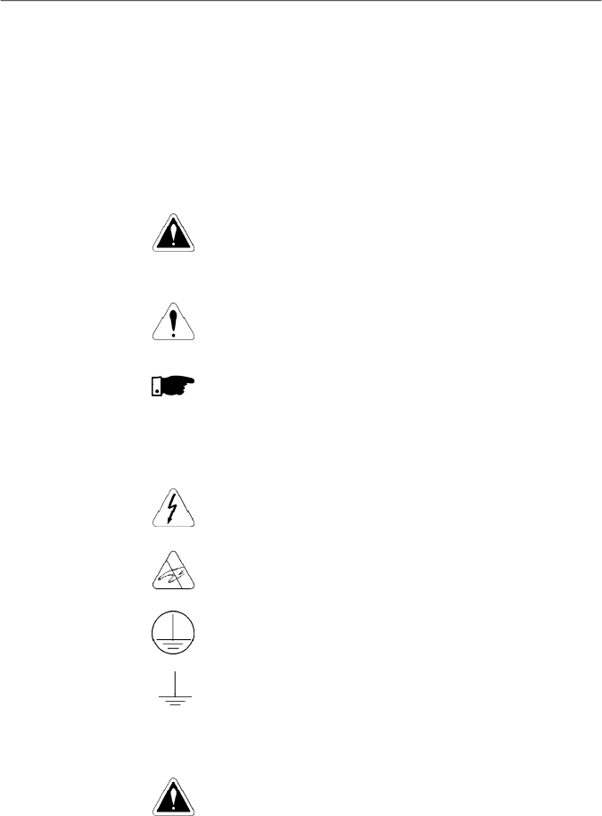
The following safety notices are used in this manual:
DANGER!
If the recommended safety notices are not strictly observed, it
can lead to serious or fatal injuries of personnel and/or material
damage.
ATTENTION!
Failure to observe the recommended safety procedures can
lead to material damage.
NOTE!
This notice provides important information for the proper
understanding and operation of the equipment.
The following symbols maybe attached to the product, serving
as safety notice:
High Voltages.
Components sensitive to electrostatic discharge. Do not
touch them without proper grounding procedures.
Mandatory connection to ground protection (PE).
Shield connection to ground.
DANGER!
Only qualified personnel should plan or implement the
installation, start- up, operation and maintenance of this
equipment. Personnel must review entire Manual before
attempting to install, operate or troubleshoot the CFW-08.
These personnel must follow all safety instructions included
in this manual and/or defined bylocal regulations.
Failure to comply with these instructions may result in
personnel injury and/or equipment damage.
1.3
PRELIMINARY
RECOMMENDA
TIONS
1.2
SAFETY NOTICES
ON THE PRODUCT
1.1
SAFETY NOTICES IN
THE MANUAL
18
CHAPTER 1 - SAFETY NOTICES
NOTE!
In this manual, qualified personnel are defined as people that are
trained to:
1.
Install, ground,power up and operate the CFW-08 according
to this manual and the local required safetyprocedures;
2.
Use of safety equipment according to the local regulations;
3.
Administer First Aid.
DANGER!
The inverter control circuit (ECC3, DSP) and the HMI-CFW08-P
are high voltage circuits and are not grounded.
DANGER!
Always disconnect the supply voltage before touching any
electrical component inside the inverter.
Many components are charged with high voltage and/or in
movement (fans), even after the incoming AC power supply has
been disconnected or switched OFF. Wait at least 10 minutes for
the total discharge of the power capacitors.
Always connect the frame of the equipment to the ground (PE) at
the suitable connection point.
ATTENTION!
All electronic boards have components that are sensitive to
electrostatic discharges. Never touch any of the electrical
components or connectors without following proper grounding
procedures. If necessary to do so, touch the properly grounded
metallic frame or use a suitable ground strap.
NOTE!
Inverters can interfere withotherelectronicequipment. In orderto
reduce this interference, adopt the measures recommended in
chapter 3 - Installation and Connection.
NOTE!
Read this entire manual before installing or operating the CFW-08.
Do not apply high voltage (high pot) test on the inverter!
If this test is necessary, contact WEG.

19
Thischapter defines the contents and purposes of this manu-
al and describes the main characteristics of the
CFW-08
frequency inverter. Identification, receiving inspections and
storage requirements are also provided.
This manual is divided into 9 chapters, providing information
to the user on how receive, install, start-up and operate the
CFW-08.
Chapter 1 -
Safety notices.
Chapter 2 -
General information and receiving the CFW-08.
Chapter 3 -
RFI filters, mechanical and electrical installation
(power and control circuit).
Chapter 4 -
Using the keypad (Human Machine Interface -
HMI).
Chapter
5 -
Start-up and steps to follow.
Chapter
6 -
Setup and read only parameters detailed
description.
Chapter
7 -
Solving problems, cleaning instructions and
preventive maintenance.
Chapter 8 -
CFW-08 optional devices description, technical
characteristics and installation.
Chapter 9 -
CFW-08 ratings, tables and technical information.
This manual provides information for the correct use of the
CFW-08. This frequency inverter is very flexible and allows
the operation in many different modes as described in this
manual.
As the CFW-08 can be applied inseveral ways,it is impossible
to describe here all of the application possibilities. WEG does
not accept any responsibility when the CFW-08 is not used
according to this manual.
No part ofthis manual maybereproduced in any form, without
the written permission of WEG.
It is important to note the software version installed in the
CFW-08, since it defines the functions and the programming
parameters of the inverter.
This manual refers to the software version indicated on the
inside cover. For example, the version 3.0X applies to versions
3.00 to 3.09, where “X” is a variable that will change due to
minor software revisions. The operation of the CFW-08 with
these software revisions are still covered by this version of
the manual.
The software version can be read in the parameter P023.
GENERALINFORMATION
2.1
ABOUT THIS
MANUAL
2.2
SOFTWARE
VERSION
CHAPTER 2

20
CHAPTER 2 - GENERAL INFORMATION
2.3
ABOUT THE CFW-08
The CFW-08 frequencyinverter provides two control options:
vector control (VVC: voltage vector control) or V/F (scalar);
both types of control can be set according to the application.
In the vector control mode, the motor performance is optimized
relating to torque and speed regulation.
The"Self-Tuning" function, available in vector control, permits
the automatic setting of the inverter parameter from the
identification (also automatic) of the parameters of the motor
connected at the inverter output.
The V/F (scalar) mode is recommended for simpler
applications such as pump and fan drives. In these cases one
can reduce the motor and inverter losses by using the
"Quadratic V/F" option, that results in energy saving.
The V/F mode is also used when more than one motor should
be driven simultaneously by one inverter (multimotor
application).
For power ratings and further technical information, refer to
Chapter 9.
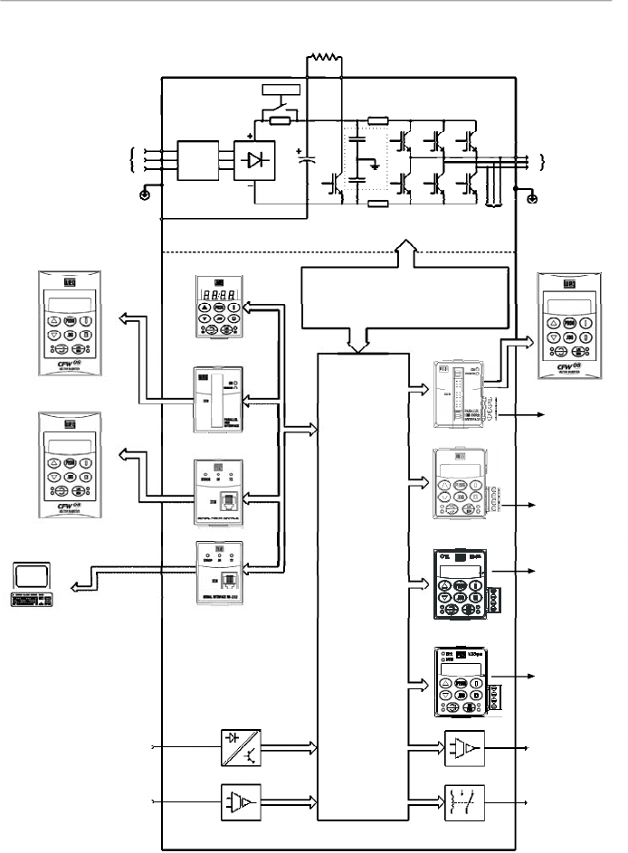
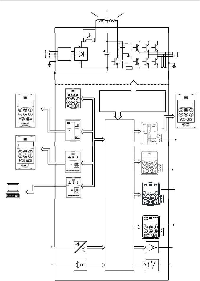
The block diagram below gives a general overview of the
CFW-08.

21
CHAPTER 2 - GENERAL INFORMATION
Figure 2.1
- Block diagram for the models:
1.6-2.6-4.0-7.0 A/200-240 V and 1.0-1.6-2.6-4.0 A/380-480 V
Power
Supply
R
S
T
PE
HMI-CFW08-RS
PC-Software
SuperDrive
Analog
Inputs
(AI1 andAI2)
Digital
Inputs
(DI1 to DI4)
Interface
RS-232 KCS-CFW08
Interface
MIS-CFW08-RS
or
HMI-CFW08-P
POWER
CONTROL
POWER SUPPLIES AND
CONTROL / POWER
INTERFACES
"ECC3"
CONTROL
BOARD
WITH DSP
Motor
U
V
W
Rsh2
Rsh1
NTC
PE
RFIFilter
HMI-CFW08-RP
Interface
MIP-CFW08-RP
or
or
Analog
Output
(AO)
Relay
Output
(RL1 and RL2)
CANopen
or
DeviceNet
KRS-485
KFB-CO or KFB-DN
RS-485
24 V Power
Supply
24 V Power
Supply
HMI-CFW08-RP
KDC-24VR-CFW08
KDC-24V-CFW08
22
CHAPTER 2 - GENERAL INFORMATION
Figure 2.2
- Block diagram for the models:
7.3-10-16-22 A/200-240 V and 2.7-4.3-6.5-10-13-16 A/380-480 V
Note:
models 16 A and 22 A/200-240 V are not fitted with optional RFI filter.
Rede de
Alimentação
R
S
T
RFI
Suppressor
Filter
(optional)
HMI-CFW08-RS
PC-Software
SuperDrive
Analog
Inputs
(AI1 andAI2)
Digital
Inputs
(DI1 to DI4)
Interface
RS-232 KCS-CFW08
Interface
MIS-
CFW08-RS
HMI-CFW08-P
POWER
CONTROL
POWER SUPPLIESAND CONTROL
/ POWER INTERFACES
"ECC3"
CONTROL
BOARD
WITH DSP
Motor
U
V
W
Rsh2
Rsh1
RPC
Pré-Carga
Braking Resistor
(External and Optional)
BR
+UD
PE
-UD
Voltage
Feedback
PE
or
or
RFI
Filter
or
Interface
MIP-
CFW08-RP
HMI-CFW08-RP
Analog
Output
(AO)
Relay
Output
(RL1 and RL2)
CANopen
or
DeviceNet
KRS-485
KFB-CO or KFB-DN
RS-485
24 V Power
Supply
24 V Power
Supply
HMI-CFW08-RP
KDC-24VR-CFW08
KDC-24V-CFW08
23
CHAPTER 2 - GENERAL INFORMATION
Figure 2.3
- Block diagram for the models:
28-33 A/200-240 V and 24-30 A/380-480 V
Note:
models 28 A and 33 A/200-240 V are not fitted with optional RFI filter.
Power
Supply
R
S
T
RFI
Suppressor
Filter
(optional)
HMI-CFW08-RS
PC-Software
SuperDrive
Analog
Inputs
(AI1 andAI2)
Digital
Inputs
(DI1 to DI4)
Interface
RS-232 KCS-CFW08
Interface
MIS-
CFW08-RS
HMI-CFW08-P
POWER
CONTROL
POWER SUPPLIES AND
CONTROL / POWER
INTERFACES
"ECC3"
CONTROL
BOARD
WITH DSP
Motor
U
V
W
Rsh1
RPC
Pré-Carga
Braking Resistor
(optional)
BR
DCR
PE
-UD
Voltage
Feedback
PE
or
or
RFI
Filter
or
Interface
MIP-
CFW08-RP
HMI-CFW08-RP
DC Link Inductor
(optional)
+UD
Analog
Output
(AO)
Relay
Output
(RL1 and RL2)
CANopen
or
DeviceNet
KRS-485
KFB-CO or KFB-DN
RS-485
24 V Power
Supply
24 V Power
Supply
HMI-CFW08-RP
KDC-24VR-CFW08
KDC-24V-CFW08
24
CHAPTER 2 - GENERAL INFORMATION
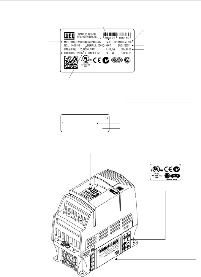
Figure 2.4
- Description and location of the nameplates on the CFW-08
2.4
CFW-08 IDENTIFICATION
Software Version
Manufacturing Date
WEG Part Number
Serial Number
CFW-08 Model
(Intelligent Code)
Rated Output Data
(Voltage, Frequency)
Lateral Label of the CFW-08
Frontal Nameplate of the CFW-08 (under the keypad)
Note:
to remove the
keypad, refer to the
instructions
in the item 8.1.1
(figure 8.2).
WEG Part Number
Serial Number
CFW-08 Model (Intelligent Code)
Software Version
Manufacturing Date
Certification Stiker
MSCFW080100T3848SOA1Z
10194356 V 4.18
1001208557 18/04/2008
Rated Input Data
(Voltage, Current, etc)

25
CHAPTER 2 - GENERAL INFORMATION
CFW-08
0040
B
2024
E
O
_ _
_ _
_ _
_ _
_ _
_ _
Z
Rated Output
Current for:
220 to 240 V:
0016 = 1.6 A
0026 = 2.6 A
0040 = 4.0 A
0070 = 7.0 A
0073 = 7.3 A
0100 = 10 A
0160 = 16 A
0220 = 22 A
0280 = 28 A
0330 = 33 A
380 to 480 V:
0010 = 1.0 A
0016 = 1.6 A
0026 = 2.6 A
0027 = 2.7 A
0040 = 4.0 A
0043 = 4.3 A
0065 = 6.5 A
0100 = 10 A
0130 = 13 A
0160 = 16 A
0240 = 24 A
0300 = 30 A
Number of
phases of
the power
supply
:
S = single
phase
T = three
phase
B = single
phase or
three phase
Manual
Language:
P =
Portuguese
E = English
S = Spanish
Power
Supply
:
2024 =
200 to 240 V
3848 =
380 to 480 V
5060
(**)
=
500-600 V
Options:
S = standard
O = with
options
Degree of
Protection:
Blank
=
s
tandard
N1 = Nema 1
N4 = Nema
4X
(**)
Human
Machine
Interface:
Blank =
s
tandard
SI = without
interface
(with dummy
panel)
WEG Series 08
Frequency
Inverter
Control Board:
Blank =
standard
control
A
1
=
c
ontrol 1
(Plus Version)
A2
=
c
ontrol
2
(Plus Version
with Als +/-
10 V)
A3 = control 3
(Plus version
with CANopen
protocol)
(*)
A4 = control 4
(Plus version
with
DeviceNet
protocol)
(*)
A5 = control
5
(**)
(for
Multipump
application)
Special
Software:
Blank =
s
tandard
End Code
RFIFilter:
Blank =
s
tandard
FA =
Category
C2
RFI
filter
(internal or
footprint)
Special
Hardware:
Blank =
s
tandard
HOW TO SPECIFY THE CFW-08 MODEL:
NOTES!
The option field (S or O) defines if the CFW-08 is a standard version or if it will be equipped with any optional devices. If the
standard version is required, the specification code ends here.
The model number has always the letter Z at the end. For example:
CFW080040S2024ESZ = standard 4.0ACFW-08 inverter, single-phase at (200 to 240) V input, with manual in English.
If the CFW-08 is equipped with any optional devices, you must fill out all fields in the correct sequence up to the last optional
device, the model number is completed with the letter Z.
Thus, for instance if the product above is required with Nema 1 degree of protection:
CFW080040S2024EON1Z =
standard C
FW-08 inverter,4.0A, single-phase, 200-240 V input,with manual in English language
and with kit for Nema 1 degree of protection.
(*)
-
The versions A3 and A4 of the control board shall be used only with the KFB-CO-CFW08 and with the KFB-DN-CFW08, respectively (refer to item 8.14 and 8.15). The parallel keypad, the
serial remote keypad, the parallel remote keypad, and the serial protocol (Modbus and WEG) cannot be used with these versions of the control board.
(**) -
For these models, contact WEG.

26
CHAPTER 2 - GENERAL INFORMATION
For the effect of this code, the standard product is conceived
as follows:
- CFW-08 with standard control board.
-
Degree of protection:
N
ema
1 for the models 22 A,
28 A and 33 A/ 200-400 V and also 13 A,16 A, 24 A
and 30 A/380-480 V, IP20 for the other models.
CFW-08 Plus - A1 is composed of the inverter and the
control board 1. Example: CFW080040S2024PO
A1
Z.
CFW-08 Plus - A2 is composed of the inverter and the
control board 2. Example: CFW080040S2024PO
A2
Z.
These models are factory setfor bipolar analog inputs (-10 V
to +10 V).
This configuration is lostwhen thefactorydefault parameters
are loaded (P204 = 5). Refer to the detailed description of
parameters P204 and P235 for further information.
CFW-08 Plus - A3 is composed of the inverter, the KFB-
CO-CFW08 kit andthe CANopen communication protocol.
Example: CFW-080040S2024PO
A3
Z.
CFW-08 Plus - A4 is composed of the inverter, the KFB-
DN-CFW08 kit and the DeviceNet communication protocol.
Example: CFW080040S2024PO
A4
Z.
CFW-08 Multipump - A5 is composed of the inverter and
the control board 5, used for multipump system applications.
7.0 A, 16.0 A, 22 A, 28 A and 33 A /200-240 V and for all
380-480 V models are just available with three-phase
power supply.
A Category C2 RFI filter (optional) can be installed inside
the inverter in models 7.3 A and 10 A/200-240 V (single-
phase) and 2.7 A, 4.3 A, 6.5 A, 10 A, 13 A, 16 A, 24 A and
30 A/380-480 V. Models 1.6 A, 2.6 A and 4.0 A/200-240 V
(single-phase) and 1.0A, 1.6A, 2.6Aand 4.0A/380-480 V
can be provided mounted on a footprint Category C2 RFI
filter (optional).
The listing of the existing models (voltage/current) is shown
in item 9.1.

27
CHAPTER 2 - GENERAL INFORMATION
The CFW-08 is supplied in cardboard boxes.
The outside of the packing box has a nameplate that is identical
to that on the CFW-08.
Please check if the CFW-08 is the one you ordered.
Check if the:
CFW-08 nameplate data matches with your purchase order.
The equipment has not been damaged during transport.
If any problem is detected, contact the carrier immediately.
If the CFW-08 is not installed immediately, store it in a clean
and dry room (storage temperatures between -25 °C [-13 °F]
and 60 °C [140 ºF]). Cover it to protect against dust, dirt or
other contamination.
ATTENTION!
When the inverter is stored for a long time, it is recommended
to power the inverter up for 1 hour every year. Make sure to
use a power supply with the following characteristics for all
models (200-240 V or 380-480 V): 220 V, single-phase or
three-phase, 50 Hz or 60 Hz, without connecting the motor to
the drive output.After powering up the drive, keep it off for 24
hours before using it again.
2.5
RECEIVING
AND
STORING
28
CHAPTER 3
INSTALLATION AND CONNECTION
This chapter describes the procedures for the electrical and
mechanical installation of the CFW-08. These guidelines
and suggestions must be followed for proper CFW-08
operation.
The location of the inverter installation is an important factor
to assure good performance and long useful life for its
components. For proper installation, we make the following
recommendations:
Avoid direct exposure to sunlight, rain, high moisture and
sea air;
Avoid exposure to explosive orcorrosive gases and liquids;
Avoid exposure to excessive vibration, dust, oil or any
conductive particles in the air.
Environment conditions:
Temperature: 0 ºC to 40 ºC (32 ºF to 104 ºF ) - nominal
conditions. From 40 ºC to50 ºC (32 ºF to 122 ºF)- with 2 %
current derating for each 1 ºC (1.8 ºF) degree above 40 ºC
(104 ºF).
Relative air humidity: 5 % to 90 % - non-condensing.
Maximum altitude: 1000 m (3,300 ft) - nominal conditions.
From 1000 m to 4000 m (3,300 to 13123.3 ft) - with 1 %
current reduction for each 100 m (328 ft) above 1000 m
(3,300 ft).
From 2000 m (6561.6 ft) to 4000 m (13123.3 ft) - a voltage
reduction of 1.1 % every 100 m (328 ft) above 2000 m
(6561.6 ft).
Pollution degree: 2 (according to EN50178 and UL508C)
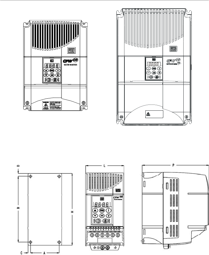
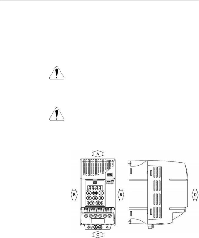
The figure 3.1 and the table 3.1, provides external mounting
specifications, and external fixing holes of the CFW-08.
3.1
MECHANICAL
INSTALLATION
3.1.1
Environment
3.1.2
CFW-08 Mounting
Specifications
Figure 3.1
- CFW-08 mounting specifications
29
CHAPTER 3 - INSTALLATION
AND CONNECTION
Figure 3.1 (cont.)
- CFW-08 mounting specifications
VIEW OF THE
MOUNTING BASE
FRONTAL
VIEW
LATERALVIEW
1 MIN. APÓS A DESENERGIZAÇÃO.
- SOMENTE REMOVA A TAMPA
- LEIA O MANUAL DE INS TRUÇÕES.
ATENÇÃO
- READ THEINS TRUCTIONSMA NUAL.
AFTER 1 MIN. POWER HAS BEEN
- ONLY REMOVE TERMINAL COVER
WARNING
DISCONNECTED.

30
CHAPTER 3 - INSTALLATION
AND CONNECTION
Inverter
Model
1.6 A / 200-240 V
2.6 A / 200-240 V
4.0 A / 200-240 V
7.0 A / 200-240 V
7.3 A / 200-240 V
10 A / 200-240 V
16 A / 200-240 V
22A/200-240 V
28A/200-240 V
33A/200-240 V
1.0 A / 380-480 V
1.6 A / 380-480 V
2.6 A / 380-480 V
2.7 A / 380-480 V
4.0 A / 380-480 V
4.3 A / 380-480 V
6.5 A / 380-480 V
10 A / 380-480 V
13 A / 380-480 V
16 A / 380-480 V
24A/380-480 V
30A/380-480 V
Width L
mm
(in)
75
(2.95)
75
(2.95)
75
(2.95)
75
(2.95)
115
(4.53)
115
(4.53)
115
(4.53)
143
(5.63)
182
(7.16)
182
(7.16)
75
(2.95)
75
(2.95)
75
(2.95)
115
(4.53)
75
(2.95)
115
(4.53)
115
(4.53)
115
(4.53)
143
(5.63)
143
(5.63)
182
(7.16)
182
(7.16)
Height H
mm
(in)
151
(5.95)
151
(5.95)
151
(5.95)
151
(5.95)
200
(7.87)
200
(7.87)
200
(7.87)
203
(7.99)
290
(11.41)
290
(11.41)
151
(5.95)
151
(5.95)
151
(5.95)
200
(7.87)
151
(5.95)
200
(7.87)
200
(7.87)
200
(7.87)
203
(7.99)
203
(7.99)
290
(11.41)
290
(11.41)
Depth P
mm
(in)
131
(5.16)
131
(5.16)
131
(5.16)
131
(5.16)
150
(5.91)
150
(5.91)
150
(5.91)
165
(6.50)
196
(7.71)
196
(7.71)
131
(5.16)
131
(5.16)
131
(5.16)
150
(5.91)
131
(5.16)
150
(5.91)
150
(5.91)
150
(5.91)
165
(6.50)
165
(6.50)
196
(7.71)
196
(7.71)
A
mm
(in)
64
(2.52)
64
(2.52)
64
(2.52)
64
(2.52)
101
(3.98)
101
(3.98)
101
(3.98)
121
(4.76)
161
(6.33)
161
(6.33)
64
(2.52)
64
(2.52)
64
(2.52)
101
(3.98)
64
(2.52)
101
(3.98)
101
(3.98)
101
(3.98)
121
(4.76)
121
(4.76)
161
(6.33)
161
(6.33)
B
mm
(in)
129
(5.08)
129
(5.08)
129
(5.08)
129
(5.08)
177
(6.97)
177
(6.97)
177
(6.97)
180
(7.08)
260
(10.23)
260
(10.23)
129
(5.08)
129
(5.08)
129
(5.08)
177
(6.97)
129
(5.08)
177
(6.97)
177
(6.97)
177
(6.97)
180
(7.09)
180
(7.09)
260
(10.23)
260
(10.23)
C
mm
(in)
5
(0.20)
5
(0.20)
5
(0.20)
5
(0.20)
7
(0.28)
7
(0.28)
7
(0.28)
11
(0.43)
11
(0.43)
11
(0.43)
5
(0.20)
5
(0.20)
5
(0.20)
7
(0.28)
5
(0.20)
7
(0.28)
7
(0.28)
7
(0.28)
11
(0.43)
11
(0.43)
11
(0.43)
11
(0.43)
D
mm
(in)
6
(0.24)
6
(0.24)
6
(0.24)
6
(0.24)
5
(0.20)
5
(0.20)
5
(0.20)
10
(0.39)
10
(0.39)
10
(0.39)
6
(0.24)
6
(0.24)
6
(0.24)
5
(0.20)
6
(0.24)
5
(0.20)
5
(0.20)
5
(0.20)
10
(0.39)
10
(0.39)
10
(0.39)
10
(0.39)
Mounting
Screw
M4
(5/32)
M4
(5/32)
M4
(5/32)
M4
(5/32)
M4
(5/32)
M4
(5/32)
M4
(5/32)
M5
(3/16)
M5
(3/16)
M5
(3/16)
M4
(5/32)
M4
(5/32)
M4
(5/32)
M4
(5/32)
M4
(5/32)
M4
(5/32)
M4
(5/32)
M4
(5/32)
M5
(3/16)
M5
(3/16)
M5
(3/16)
M5
(3/16)
Weigth
kg
(lb)
1.0
(2.2)
1.0
(2.2)
1.0
(2.2)
1.0
(2.2)
2.0
(4.4)
2.0
(4.4)
2.0
(4.4)
2.5
(9.8)
6
(2.36)
6
(2.36)
1.0
(2.2)
1.0
(2.2)
1.0
(2.2)
2.0
(4.4)
1.0
(2.2)
2.0
(4.4)
2.0
(4.4)
2.0
(4.4)
2.5
(5.5)
2.5
(5.5)
6
(2.36)
6
(2.36)
Degree of
Protection
IP20 / Nema 1
(*)
IP20 / Nema 1
(*)
IP20 / Nema 1
(*)
IP20 / Nema 1
(*)
IP20 / Nema 1
(*)
IP20 / Nema 1
(*)
IP20 / Nema 1
(*)
IP20/Nema 1
IP20/Nema 1
IP20/Nema 1
IP20 / Nema 1
(*)
IP20 / Nema 1
(*)
IP20 / Nema 1
(*)
IP20 / Nema 1
(*)
IP20 / Nema 1
(*)
IP20 / Nema 1
(*)
IP20 / Nema 1
(*)
IP20 / Nema 1
(*)
IP20 / Nema 1
IP20 / Nema 1
IP20 / Nema 1
IP20 / Nema 1
Dimensions
Fixing base
Table 3.1
- CFW-08 dimensions for mechanical installation of the several models
(*)
These models are Nema 1 only with the KN1-CFW08-MX optional.
31
CHAPTER 3 - INSTALLATION
AND CONNECTION
When installing the CFW-08, free space around the inverter
must be left as indicated in figure 3.2.
Table 3.2 shows the
required free spaces.
Install the inverter in vertical position according to the following
recommendations:
1)
Install the inverter on a flat surface.
2) Do not install heatsensitive components immediately above
the
inverter.
ATTENTION!
When inverters are installed side by side, maintain the
minimum recommended distance B.
W
hen inverters are installed top and bottom, maintain the
minimum recommended distance
A + C and deflect the hot
air coming from the inverter below.
ATTENTION!
Provide independent conduits for signal, control and power
conductors separation (refer to item 3.2 - Electrical Installation).
Use separate conduits or trunking for control and power wiring
(see item 3.2 - Electrical Installation).
Figure 3.2
- Free spaces for cooling
3.1.3
Positioning and Fixing

32
CHAPTER 3 - INSTALLATION
AND CONNECTION
CFW-08 Model
1.6 A / 200-240 V
2.6 A / 200-240 V
4.0 A / 200-240 V
7.0 A / 200-240 V
1.0 A / 380-480 V
1.6 A / 380-480 V
2.6 A / 380-480 V
4.0 A / 380-480 V
7.3 A / 200-240 V
10 A / 200-240 V
16 A / 200-240 V
2.7 A / 380-480 V
4.3 A / 380-480 V
6.5 A / 380-480 V
10 A / 380-480 V
22 A / 200-240 V
13 A / 380-480 V
16 A / 380-480 V
28A/200-240 V
33A/200-240 V
24A/380-480 V
30A/380-480 V
A
B
C
D
30 mm
1.18 in
5 mm
0.20 in
50 mm
2 in
50 mm
2 in
35 mm
1.38 in
15 mm
0.59 in
50 mm
2 in
50 mm
2 in
40 mm
1.57 in
30 mm
1.18 in
50 mm
2 in
50 mm
2 in
50 mm
2 in
40 mm
1.57 in
60 mm
2.36 in
50 mm
2 in
Table 3.2
- Recommended free spaces
When inverters are installed inside closed metallic panels or
boxes provide suitable air exhaustion by ensuring that the
ambient temperature remains within the allowed range. For
wattlosses refer to item 9.1 of this manual.
For reference, table 3.3 shows the cooling airflow for each
inverter model.
Inverter Cooling Method:
internal fan, flow direction from
the bottom to the top.
3.1.3.1
Panel Mounting
Table 3.3
- Cooling air flow requirements
CFW
-
08 Inverter Model
CFM
I/s
m
3
/min
4.0
A, 7.0
A/200
V
2.6
A, 4.0
A/400
V
6.0
2.8
0.17
7.3
A, 10
A, 16
A/200
V
6.5
A, 10
A/400
V
18.0
8.5
0.51
13
A, 16
A/400
V
18.0
8.5
0.51
22
A/200
V
22.0
10.4
0.62
28
A/200
V
24
A/400
V
36.0
17.0
1.02
33
A/200
V
30
A/400
V
44.0
20.8
1.25
33
CHAPTER 3 - INSTALLATION
AND CONNECTION
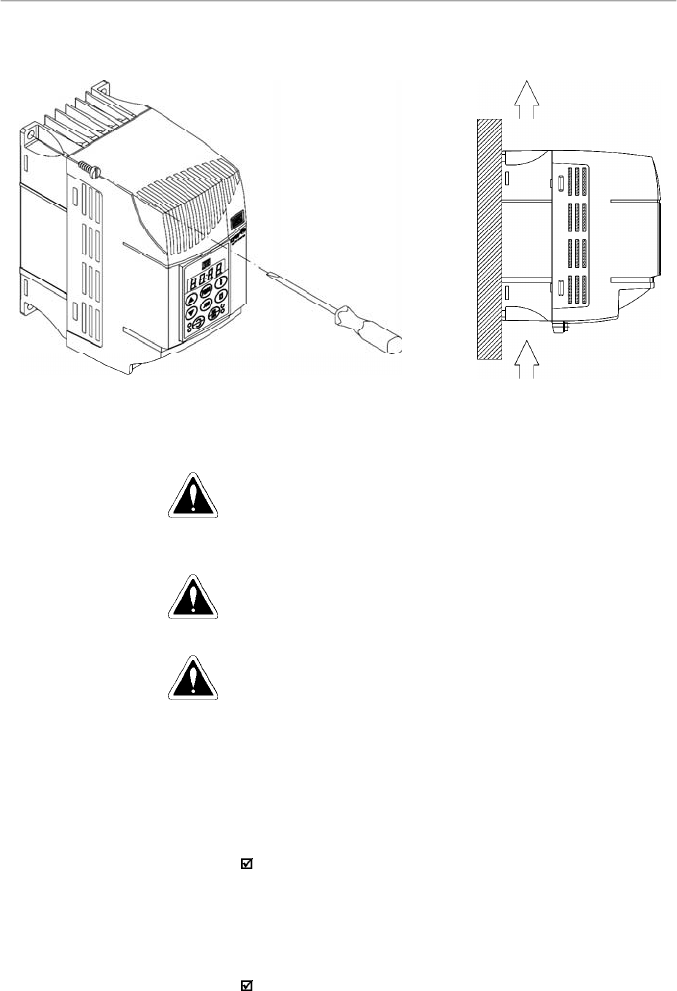
3.1.3.2
Surface Mounting
Figure 3.3 shows the surface installation procedures of the
CFW-08.
Figure 3.3
- Mounting procedures for CFW-08
3.2
ELECTRICAL
INSTALLATION
DANGER!
The information below will be a guide to achieve a proper
installation. Also follow all applicable local standards for
electrical installations.
DANGER!
Be sure the AC input power has been disconnected before
making any terminal connection.
DANGER!
Do not use the CFW-08 as an emergency stop device. For
this purpose provide other additional mechanical means.
The power connection terminals can be of different sizes and
configurations, depending on theinverter model, as shown in
figure 3.4.
Description of the power terminals:
L/L1, N/L2 and L3 (R, S ,T):AC power supply.
The models of the line voltage 200-240 V (excepting 7.0A,
16A, 22A, 28A, and 33A) can be operated on two phases
(single-phase operation) without rated current reduction. In
this case theAC power supply can be connected to any 2
terminals of the 3 inputs terminals.
U, V, W: connection to the motor.
3.2.1
Power / Grounding
Terminals
AIR FLUX
34
CHAPTER 3 - INSTALLATION
AND CONNECTION
-UD: negative pole of the DC link circuit is not available on
the models 1.6A-2.6A-4.0A-7.0A/200-240 V and models
1.0 A-1.6 A-2.6 A-4.0 A/380-480 V. It is used when the
inverter supplied by DC voltage (with the terminal +UD). In
order to avoid an incorrect braking resistor connection
(mounted outside the inverter), thereis a protective rubber
plug on this terminal, which must be removed if the –UD
terminal has to be used.
BR: Connection for the braking resistor.
Notavailableonthemodels1.6A-2.6A-4.0A-7.0A/200-240V
and on the models 1.0A-1.6A-2.6A-4.0A/380-480 V.
+UD: positive pole of the DC link circuit, not available on
the models 1.6 A-2.6 A-4.0A-7.0 A/200-240 V and on the
models 1.0 A-1.6 A-2.6 A-4.0 A/380-480 V. It is used to
connect the braking resistor (with the BR terminal) or when
the inverter shall be supplied by with DC voltage (jointly
with the –UD terminal.
DCR: Connection for the external DC link circuit inductor
(optional). It is only available on the models 28Aand 33A/
200-240 V and on the models 24 A and 30 A/380-480 V.
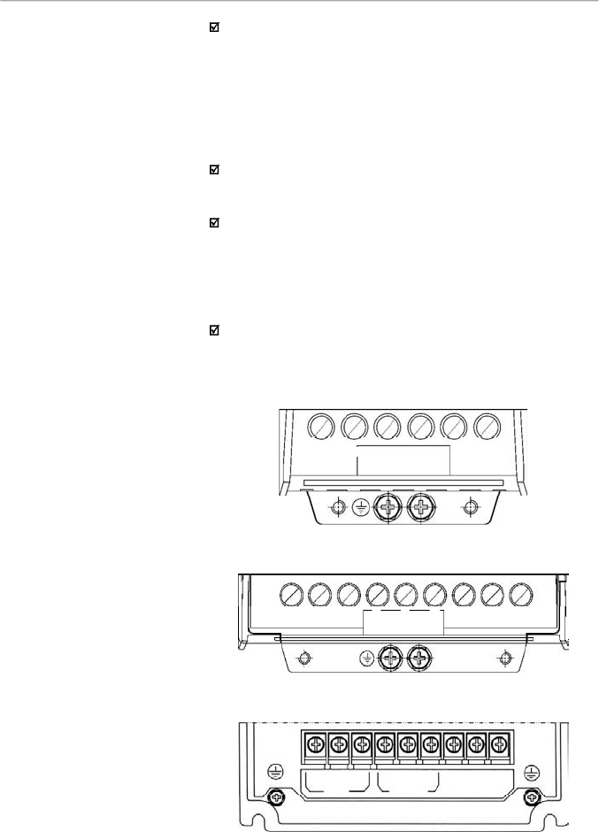
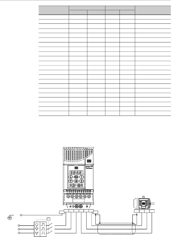
c) 22 A/200-240 V and 13-16 A/380-480 V models
b) 7.3-10-16A/200-240 V and 2.7-4.3-6.5-10A/380-480 V models
a) 1.6-2.6-4.0-7.0A/200-240 V and 1.0-1.6-2.6-4.0A/380-480 V models
Figure 3.4 a) to c)
- Power terminals
L3
U
V
W
L/L1
N/L2
-Ud
BR
+
Ud
L3
L/L1
N/L2
U
V
W
1
R
2
S
3
T
4
U
5
V
6
W
7
-UD
8
BR
9
+UD
LINE
MOTOR
35
CHAPTER 3 - INSTALLATION
AND CONNECTION
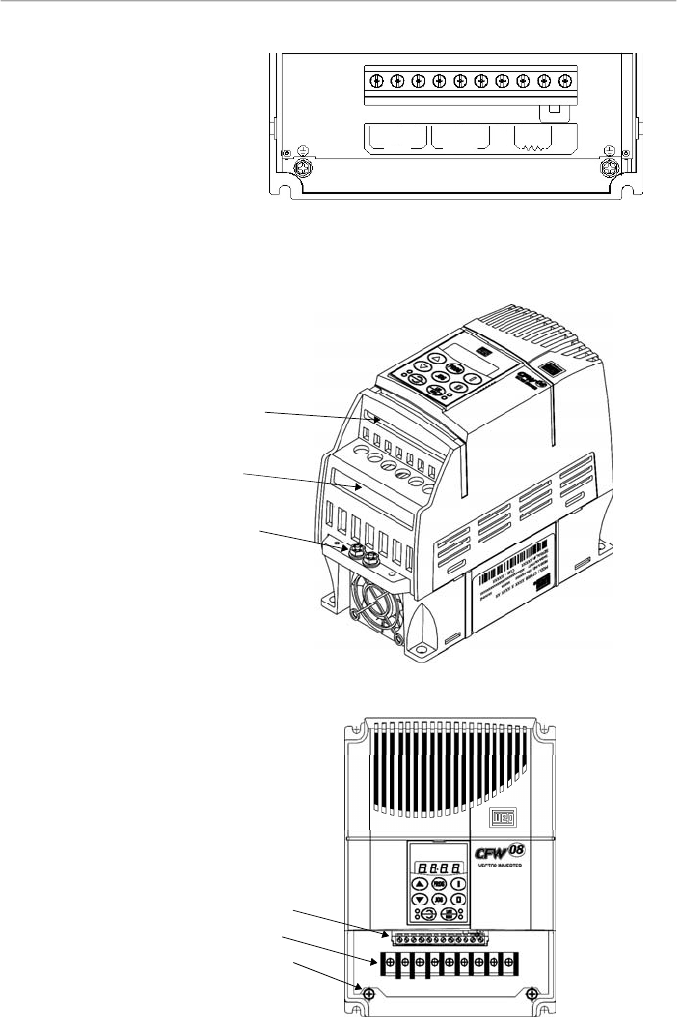
3.2.2
Location of the Power
Terminals, Grounding
Terminals and Control
Terminal Connections
Control XC1
Power
Grounding
a) 1.6-2.6-4.0-7.0-7.3-10-16A/200-240 V and
1.0-1.6-2.6-2.7-4.0-4.3-6.5-10A/380-480 V models
Figure 3.5 a) and b)
- Location of the power, grounding and
control connections
b) 22-28-33A/200-240 V and 13-16-24-30A/380-480 V models
Control XC1
Power
Grounding
Figure 3.4 (cont.) d)
- Power terminals
d) 28-33A/200-240 V and 24-30A/380-480 V models
1
R
2
S
3
T
4
U
5
V
6
W
7
-UD
8
BR
9
+UD
LINE
MOTOR
10
DCR
36
CHAPTER 3 - INSTALLATION
AND CONNECTION
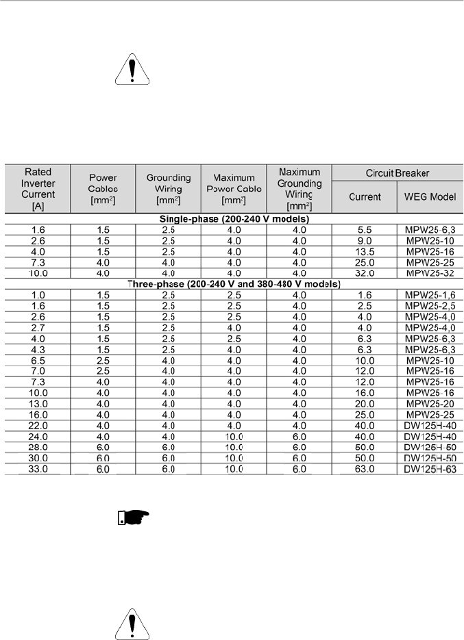
3.2.3
Power/Grounding
Wiring and
Circuit Breakers
ATTENTION!
Install the inverter and power cables distant from sensitive
equipment and wirings by 0.25 m (0.82 ft), for instance PLCs,
temperature controllers, thermocouple cables, etc.
Use the recommended wire cross section and circuit breakers
as shown in table 3.4. Use only copper wire (70 ºC [158 ºF]).
NOTE!
The wire sizing in table 3.4 shall be used as reference values
only. The exact wire sizing depends on the installation
conditions and the maximum acceptable line voltage drop.
The recommended tightening torque is shown in table 3.5.
ATTENTION!
The use of mini circuit breakers (MBU) is not recommended
due to the level of the magnetic protection.
Table 3.4
- Recommended wiring and circuit breakers – use only copper wire (70 ºC [158 ºF])
37
CHAPTER 3 - INSTALLATION
AND CONNECTION
Model
1.6 A / 200-240 V
2.6 A / 200-240 V
4.0 A / 200-240 V
7.0 A / 200-240 V
7.3 A / 200-240 V
10.0 A / 200-240 V
16.0 A / 200-240 V
22.0 A / 200-240 V
28.0 A / 200-240 V
33.0 A / 200-240 V
1.0 A / 380-480 V
1.6 A / 380-480 V
2.6 A / 380-480 V
2.7 A / 380-480 V
4.0 A / 380-480 V
4.3 A / 380-480 V
6.5 A / 380-480 V
10.0 A / 380-480 V
13.0 A / 380-480 V
16.0 A / 380-480 V
24.0 A / 380-480 V
30.0 A / 380-480 V
Grounding Wiring
N.m
Lbf.in
0.5
4.34
0.5
4.34
0.5
4.34
0.5
4.34
0.5
4.34
0.5
4.34
0.5
4.34
0.5
4.34
0.5
4.34
0.5
4.34
0.5
4.34
0.5
4.34
0.5
4.34
0.5
4.34
0.5
4.34
0.5
4.34
0.5
4.34
0.5
4.34
0.5
4.34
0.5
4.34
0.5
4.34
0.5
4.34
Power Cables
N.m
Lbf.in
1.0
8.68
1.0
8.68
1.0
8.68
1.0
8.68
1.76
15.62
1.76
15.62
1.76
15.62
1.76
15.62
1.76
15.62
1.76
15.62
1.2
10.0
1.2
10.0
1.2
10.0
1.76
15.62
1.2
10.0
1.76
15.62
1.76
15.62
1.76
15.62
1.76
15.62
1.76
15.62
1.76
15.62
1.76
15.62
Table 3.5
- Recommended tightening torque for power and grounding connections
3.2.4
Power Connections
a) 1.6-2.6-4.0-7.0A/200-240 V and 1.0-1.6-2.6-4.0 A/380-480 V models - Three phase power supply
Type of Screwdriver for
the Power Terminal
Philips Number PH2
Philips Number PH2
Philips Number PH2
Philips Number PH2
Philips Number PH2
Philips Number PH2
Philips Number PH2
Philips Number PH2
Pozidriv Number PZ2
Pozidriv Number PZ2
Philips Number PH2
Philips Number PH2
Philips Number PH2
Philips Number PH2
Philips Number PH2
Philips Number PH2
Philips Number PH2
Philips Number PH2
Philips Number PH2
Philips Number PH2
Pozidriv Number PZ2
Pozidriv Number PZ2
Figure 3.6 a)
- Power and grounding connections
PE
R
S
T
Power Supply
Circuit Breaker
PE
T
Q1
R
S
T
U
V
W
PE
Shielding
PE
W
V
U
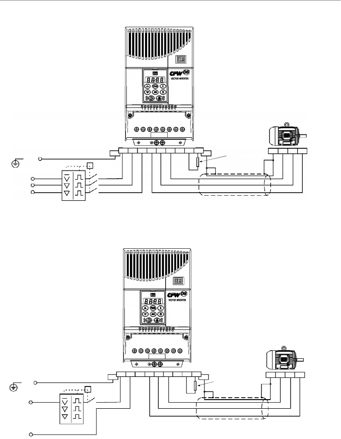
38
CHAPTER 3 - INSTALLATION
AND CONNECTION
c) 1.6-2.6-4.0-7.3-10 A / 200-240 V models - Single phase power supply
Figure 3.6 b) and c)
- Power and grounding connections
(*)
In case of single-phase power supply with phase and neutral cable, connect only the phase cable to the
circuit breaker.
(**)
In the 1.6 A -2.6 A and 4.0 A models, the terminals to connect the braking resistor are not available.
PE
PE
T
Q1
R
S
T
U
V
W
PE
Shielding
PE
-Ud
BR
+
Ud
Braking
Resistor
(**)
(refer to item
8.23)
W
V
U
Phase
Neutral
Power Supply
Circuit Breaker
(*)
b) 7.3-10-16-22A/200-240 V and 2.7-4.3-6.5-10-13-16A/380-480 V models - Three phase power supply
PE
R
S
T
Power Supply
PE
T
Q1
R
S
T
U
V
W
PE
Shielding
PE
-Ud
BR
+
Ud
Braking
Resistor
(refer to item
8.23)
W
V
U
Circuit Breaker
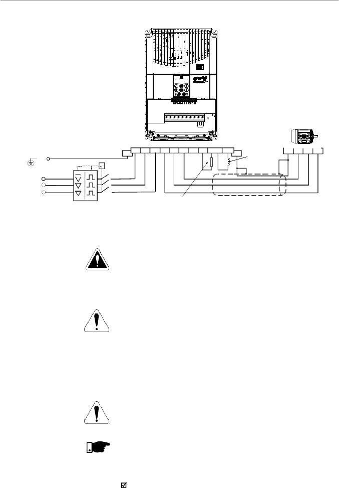
39
CHAPTER 3 - INSTALLATION
AND CONNECTION
Figure 3.6 d)
- Power and grounding connections
d) 28-33 A / 200-240 V and 24-30 A / 380-480 V models - Three phase power supply
DANGER!
Provide an AC disconnecting switch to switch OFF the input
power to the inverter. This device shall disconnect the inverter
from the AC input supply when required (e. g. during
maintenance services).
ATTENTION!
A contactor or another device that frequently disconnects and
reapplies the AC supply to the inverter in order to start and
stop the motor may cause damage to the inverter power
section. The drive is designed to use control input signals for
startingand stopping the motor. If used, the input device must
not exceed one operation every 6 minutes otherwise the
inverter may be damaged.
ATTENTION!
The AC input for the inverter must have a grounded neutral
conductor.
NOTE!
TheAC input must be compatible with the inverter rated voltage
Power supply line capacity:
30 kArms symmetrical amperes, 200-480 Vac maximum,
when protected by fuses rated maximum of 200 % device
input current. Voltage is the same as the device maximum
input voltage. In orderto comply with the UL standard,UL
recognized fuses must be used.
3.2.4.1
AC Input Connection
PE
T
Q1
R
S
T
U
V
W
PE
Shielding
PE
-Ud
BR
+
Ud
Braking Resistor
W
V
U
Phase
Power Supply
DCR
DC Link
Inductor
(Optional)
PE
R
S
T
Circuit Breaker
40
CHAPTER 3 - INSTALLATION
AND CONNECTION
3.2.4.3
Grounding
Connections
If the CFW-08 is installed in networks which can supplymore
than 30.000 Arms, you must provide suitable protection
circuits such as fuses and circuit breakers.
DC link inductor / line reactors
The requirements for use of line reactors or DC link inductor
depend on several application factors. Refer to item 8.21.
NOTE!
Capacitors for power factor correction are not required at the
input (L/L1, N/L2, L3 or R,S, T)and theymust notbe connected
at the output (U, V, W).
The inverter is provided with electronic protection against
motor overload. This protection must be set according to the
specific motor. When the same inverter drives several motors,
use individual overload relays for each motor. Maintain the
electrical continuity of the motor cable shield.
ATTENTION!
If a disconnect switch or a contactor is inserted in the motor
supply line, do not operate them with motor running or when
inverter is enabled. Maintain the electrical continuity of the
motor cable shield.
Dynamic braking (DB)
When inverters with dynamic braking (DB) are used, the DB
resistor shall be mounted externally. Figure 8.31 shows how
to connect the braking resistor. Size it according to the
application,not exceeding the maximum current of the braking
circuit. For the connection between inverter and the braking
resistor, use twisted cable. Provide physical separation
between this cable and the signal and control cables. When
the DB resistor is mounted inside the panel, consider watt
loss generated when defining the panel ventilation.
DANGER!
The inverter must be grounded to a protective earth (PE) for
safety purposes.
The earth or ground connection must comply with the local
regulations.For grounding, use cables with cross sections as
indicated in table 3.4. Make the ground connection to a
grounding bar or to the general grounding point (resistance
10 ohms).
DANGER!
Do not share the ground wiring with other equipment that
operates with high currents(for instance:high voltage motors,
welding machines, etc). If several inverters are used together,
refer to figure 3.7.
3.2.4.2
Output
Connections
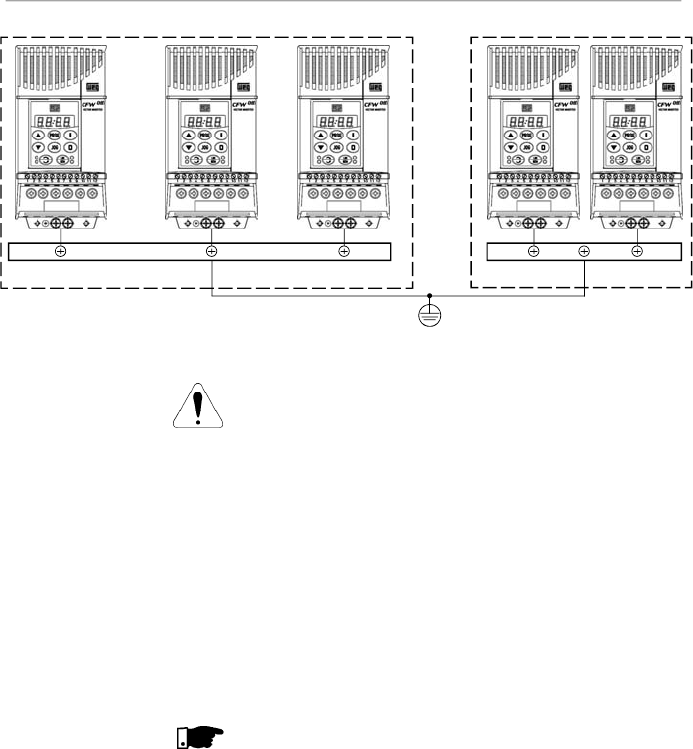
41
CHAPTER 3 - INSTALLATION
AND CONNECTION
ATTENTION!
The AC input for the inverter must have a grounded neutral
conductor.
EMI – Electromagnetic interference
When electromagnetic interference (EMI) generated by the
inverter interferes in theperformance of other equipment,use
shielded wires, or install the motor wires in metallic conduits.
Connect one end of the shielding to the inverter grounding
point and the other end to the motor frame.
Motor frame
Always ground themotor frame. Ground the motor in the panel
where the inverter is installed or ground it to the inverter. The
inverter output wiring must be laid separately from the input
wiring as well as from the control and signal cables.
NOTE!
Do not use neutral conductor for grounding purposes.
Figure 3.7
- Grounding connections for more than one inverter
GROUNDING BAR
INTERNAL
T
O THE P
ANEL
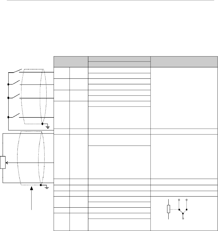
42
CHAPTER 3 - INSTALLATION
AND CONNECTION
3.2.5
Signal and Control
Connections
The
signal connections
(analog inputs/outputs
)
and control
connections (
digital inputs and relay outputs
)
are
made on
the XC1 connector of control board (
refer to the
location in
f
igure 3.5,
item
3.2.2).
There are two configurations for the control board: standard
version (CFW-08 line)
and Plus version (CFW-08 Plus line),
as shown below:
Figure 3.8
- XC1 control terminal description (standard control board - CFW-08)
Note:
NC = Normally Closed Contact, NO = Normally Open Contact.
XC1Terminal
1
DI1
2
DI2
3
DI3
4
DI4
5
GND
6
AI1 or
DI5 or
PTC1
7
+10 V
8
GND
9
10
N.C.
11
Commom
12
N.O.
Description
Factory Default Function
Digital Input 1
General Enable
Digital Input 2
FWD / REV
Digital Input 3
Reset
Digital Input 4
Start/Stop
0 V Reference
Analog Input 1 or Digital Input 5
or PTC Input
Frequency / Speed Reference
(remote mode)
Potentiometer Reference
0 V Reference
Not Used
Relay Output 1 - N.C. Contact
No Fault (P277 = 7)
Relay 1 Common Point
Relay 1 - N.O. Contact
No Fault (P277 = 7)
Specifications
4 isolates digital inputs
- Logic NPN
Minimum high level: 10 Vdc
Maximum high level: 30 Vdc
Maximum low level: 3 Vdc
- Logic PNP
Maximum low level: 10 Vdc
Minimum high level: 21.5 Vdc
Maximum high level: 30 Vdc
Input current: -11 mA
Maximum input current: -20 mA
Not connected to PE
( 0 to10) Vdc (0 to 20) mA (4 to 20)
mA (figure 3.10)
Impedance: 100 k
(voltage input)
and 500
(current input).
- Linearity error < 0,25 %
- Maximum voltage input: 30 Vdc
Forfurther information refer to P235
detailed parameter description
+10 Vdc, ± 5 %, capacity: 2 mA
Contact capacity:
0.5 A / 250 Vac
Relay 1
10
12
11
CCW
CW
5k
Factory Default
Settings
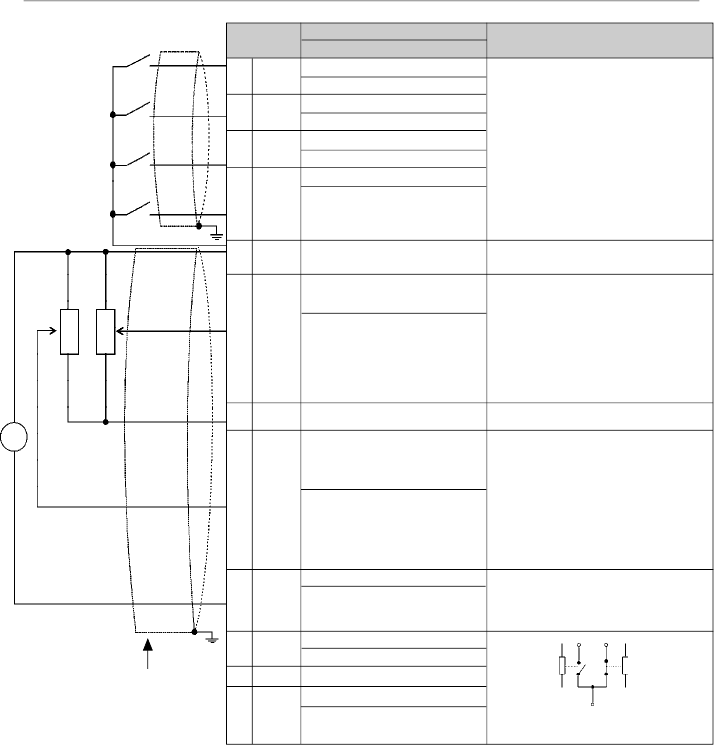
43
CHAPTER 3 - INSTALLATION
AND CONNECTION
Figure 3.9
- Description of the XC1 connector for the control board A1 (CFW-08 Plus), control board A2
(CFW-08 Plus with AIs -10 V a +10 V), control board A3 (CFW-08 Plus with CANopen protocol) and control
board A4 (CFW-08 Plus with DeviceNet protocol)
Connector
XC1
1
DI1
2
DI2
3
DI3
4
DI4
5
GND
6
AI1 or
DI5 or
PTC1
7
+10 V
8
AI2 or
DI6 or
PTC2
9
AO
10
N.C
11
Commom
12
N.O.
Description
Factory Default Function
Digital Input 1
No Function or General Enable
Digital Input 2
FWD / REV
Digital Input 3
Reset
Digital Input 4
No Function or Start/Stop
0 V Reference
Analog Input1 or Digital Input 5
or PTC1 Input
Frequency/Speed Reference
(remote mode)
Potentiometer Reference
Analog Input 2 or Digital Input
Digital 6 or PTC2 Input
Not Used
Analog Output
Output Frequency (Fs)
Relay 2 - N.C. Contact
Fs>Fx (P279 = 0)
Relays Common Points
Relay 1 - N.O. Contact
No Fault (P277 = 7)
Specifications
4 isolates digital inputs
- Logic NPN
Minimum high level: 10 Vdc
Maximum high level: 30 Vdc
Maximum low level: 3 Vdc
- Logic PNP
Maximum low level: 10 Vdc
Minimum high level: 21.5 Vdc
Maximum high level: 30 Vdc
Input current: -11 mA
Maximum
input current: -20 mA
Not connected to PE
(0to10)Vdcor(0to20)mAor(4to20)mA
and (-10 to +10) Vdc
(*)
(figure 3.10)
Impedance: 100 k
(voltage input) and
500
(currentinput)
- Linearity error < 0,25 %
- Maximum voltage input: 30 Vdc
For further information refer to P235
detailed parameter description
+10 Vdc, ± 5 %, capacity: 2 mA
(0 to10) Vdc or (0 to 20) mA or (4 to
20) mA
and (-10 to +10) Vdc
(*)
(figure
3.10) Impedance: 100 k
(voltage
input) and 500
(current input)
- Linearity error < 0.25 %
- Maximum voltage input: 30 Vdc
For further information refer to P239
detailed parameter description
(0to10)Vdc
or(0to20)mAor(4to20)mA,
RL
10k
Resolution: 8 bits
Linearity Error < 0.25 %
Contact capacity:
0.5 A / 250 Vac
Relay 1
11
Relay 2
12
10
RPM
-
+
CCW
CW
CCW
CW
10k
Note:
NC = Normally Closed Contact, NO = Normally Open Contact.
(*)
This option is available only for versionA2 of the control board (refer to item 2.4).
In version A2 the linearity error is smaller than 0.50 %.
10k
Factory Default
Settings
Refer to item 2.4 for additional information on the control boards.

44
CHAPTER 3 - INSTALLATION
AND CONNECTION
AI1
AO
DI
AI2
Figure 3.10
-
Jumpers position for selecting the analog inputs and outputs operation mode (voltage - 0 to 10 Vdc
or current - 0 to 20 mA / 4 to 20 mA) as well as the digital inputs operation mode (high logic level - PNP or low
logic level - NPN). Refer to the digital inputs definition on items 3.2.5.1 and 3.2.5.2
I/O
DI1 to DI4
AO
AI1
AI2
Factory Default Setting
Refer to the parameters P263,
P264, P265 and P266
Output Frequency
Frequency / Speed Reference
(remote mode)
No Function
DIP
Switch
S1:1
S1:2
S1:3
S1:4
Selection
OFF: digital inputs as low active (NPN)
ON: digital inputs as high active (PNP)
ON: (0 to 10) Vdc
OFF: (4 to 20) mA or (0 to 20) mA
OFF: (0 to 10) Vdc or DI5
ON: (4 to 20) mA or (0 to 20) mA or PTC
OFF: (0 to 10) Vdc or DI6
ON: (4 to 20) mA or (0 to 20) mA or PTC
Table 3.6
- Dip switch configuration (inputs and outputs)
As a default, the analog inputs and outputs are set to voltage
mode (0 to 10) Vdc and the digital inputs are set to active
(NPN logic). Change it byusing DIP switch S1 (refer to figure
3.10) on the control board and by setting parameters P235,
P239 and P253 (refer to table 3.6).
NOTE!
If it's used a (4 to 20) mA signal, set parameter P235,P239
and P253 that defines the signal type at AI1, AI2 and AO
respectively.
The parameters related to the analog inputs are: P221,
P222,P234, P235, P236, P238, P239, P240, P251, P252,
P253. For more details, please refer to chapter 6.
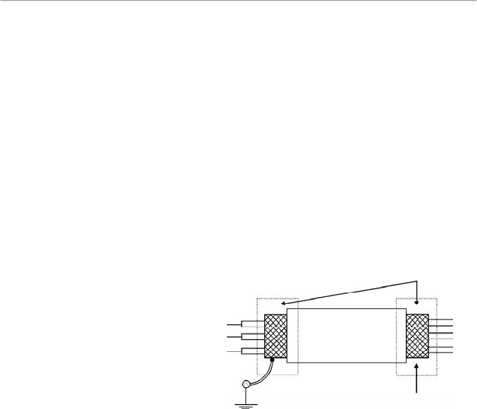
45
CHAPTER 3 - INSTALLATION
AND CONNECTION
Inverter side
Insulate with tape
Figure 3.11
- Shield connection
Connect to earth: bolts are
located on the heatsink
Do not ground
During the signal and control wire installation note the
following:
1)
Cable cross section: (0.5 to 1.5) mm²/(20 to 14) AWG
2)
Maximum Torque: 0.50 N.m (4.50 lbf.in).
3)
XC1 wiring must be connected with shielded cables and
installed at least 10 cm (3.9 in) minimum separately from
other wiring (power, control at 110/220 V, etc) for lengths
up to 100 m (330 ft) and 25 cm (9.8 in) minimum for total
lengths over 100 m (330 ft). If the crossing of these cables
is unavoidable, install them perpendicular, maintaining a
mimimum separation distance of 5 cm (2 in) at the crossing
point.
Connect the shield as shown below:
4)
For wiring distances longer than 50 m (150 ft),it is necessary
to use galvanic isolators for the XC1:5 to 9 signals.
5)
Relays, contactors, solenoids or eletromagnetic braking
coils installed near the inverters can generate interferences
in the control circuit.To eliminate this interference, connect
RC suppressor in parallel with the coils of AC relays.
Connect free-wheeling diode in case of DC relays.
6)
When external keypad (HMI) is used (refer to chapter 8),
separete the cable that connects the keypad to the inverter
from other cables, maintaining a minimum distanceof 10cm
(3.9 in) between them.
7)
When analog reference (AI1 or AI2) is used and the
frequency oscillates (problem caused by eletromagnetic
interference) connect XC1:5 to the inverter heatsink.
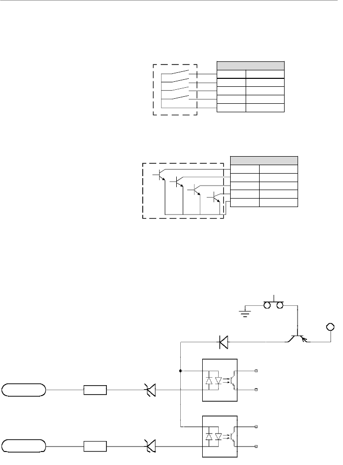
46
CHAPTER 3 - INSTALLATION
AND CONNECTION
3.2.5.1
Digital Inputs as
Low Level Active
(S1:1 to OFF)
Con
n
ector XC1
1
DI1
2
DI2
3
DI3
4
DI4
5
GND
b) Example using a PLC - NPN transistor output
Co
n
nector XC1
1
DI1
2
DI2
3
DI3
4
DI4
5
GND
Figure 3.12 a) and b) -
Digital inputs
as low logic level configuration
PLC output relay
COM
PLC output NPN
GND (PLC)
In these options, the equivalent circuit at inverter side is
presented in the figure 3.13.
This option can be selected when a PLC is used with relayor
transistor output is used (low logic level to activate the DI).
a) Example using a PLC - relay output
Figure 3.13
- Equivalent circuit – Digital inputs as low logic level
XC1:1
XC1:2
DI2
DI1
1
2
2k
2k
10 V
10 V
SMD
Optocoupler
SMD
Optocoupler
+12 V
S1:1 in OFF
GND
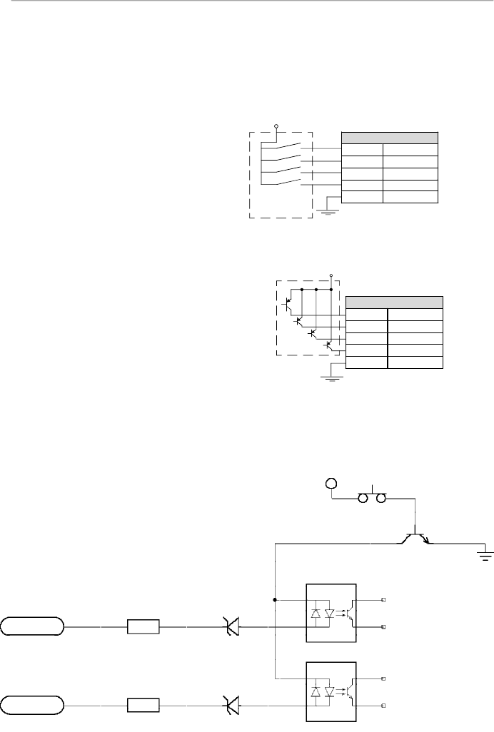
47
CHAPTER 3 - INSTALLATION
AND CONNECTION
This option can be selected when a PLC is used with PNP
transistor output (high logic level to activate the DI) or PLC
with relay output is used. For this last alternative you must
apply an external power supply 24 V +/- 10 %.
3.2.5.2
Digital Input as
High LevelActive
(S1:1 to ON)
Figure 3.14 a) and b
) - Configuration of the active digital inputs as
high logic level
In this option, the equivalent circuit at the inverter side is
presented in the figure 3.15.
b) Example using a PLC - PNP transistor output
a) Example using a PLC - relay output
Con
n
ector XC1
1
DI1
2
DI2
3
DI3
4
DI4
5
GND
24 V (internal PLC)
PLC output
PNP
GND (PLC)
PLC output relay
GND (source
external 24 V)
24 V (external)
Co
n
nector XC1
1
DI1
2
DI2
3
DI3
4
DI4
5
GND
Figure 3.15
-
Equivalent circuit - Digital inputs as high logic level
XC1:1
XC1:2
DI2
DI1
1
2
2k
10 V
10 V
SMD
Optocoupler
SMD
Optocoupler
+12 V
S1:1 in ON
2k
GND
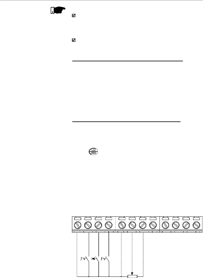
48
CHAPTER 3 - INSTALLATION
AND CONNECTION
DI1 - No Function or
General Enabling
DI2 - FWD / REV
DI3 - Reset
COM
AI1
+10 V
AI2
AO1
NC
Common
NO
DI4 - No Function
or Start/Stop
S1: FWD/REV
S2: Reset
S3: Start/Stop
R1: Potentiometer for
speed setting
1
2
3
4
5
6
7
8
9
10
11
12
NOTES!
The inverter is factory default programmed with the digital
inputs as low level active (S1:1 in OFF). When the digital
inputs are used as high level active, you must set the jumper
S1:1 to ON.
The jumper S1:1 selects the high level or low level active
for all 4 digital inputs. You can not select them separately.
3.2.6
Typical Terminal
Connections
Connection 1 - Keypad Start/Stop (local mode)
With the factory default programming, you can operate the
inverter in local mode with the minimum connections shown in
figure 3.6 (Power) and without control connections. This
operation mode is recommended for users who are operating
the inverter for the first time. Note that there is no need of
connection of control terminals.
For start-up accordingto this operation mode, referto
c
hapter5.
Connection 2 - Wire Start/Stop (remote mode)
Valid for factory default programming and inverter operating
in remote mode. For the factory default programming, the
selection of the operation mode
(local/remot
e
)
is made via
the key
(default is local).
The figure 3.16 shows the inverter terminal connection for this
type of driving.
Figure 3.16
- XC1 wiring for connection 2
R1
S3
S2
S1
5k
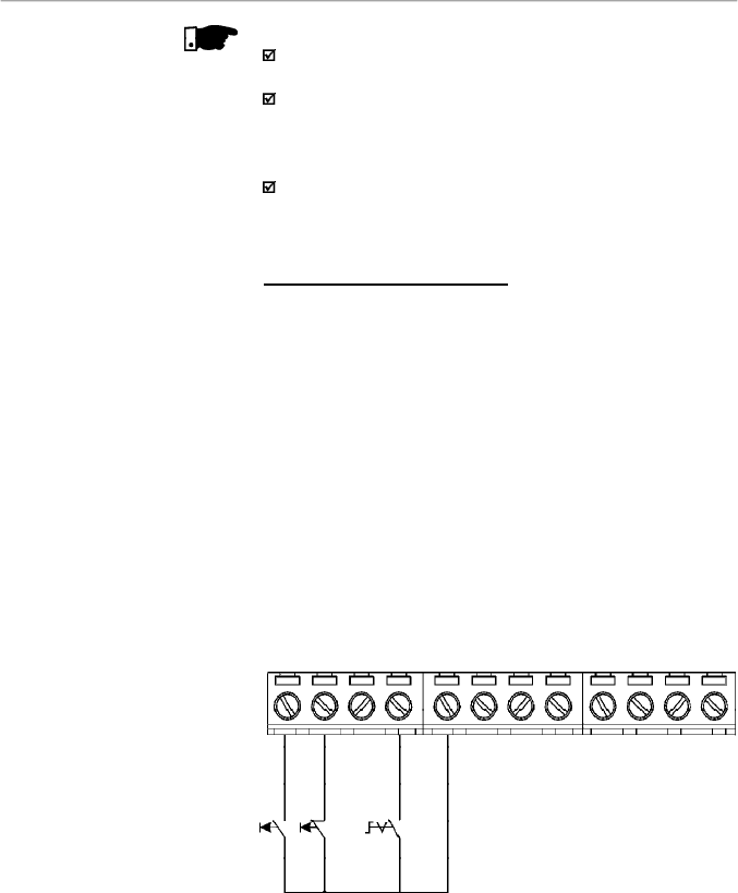
49
CHAPTER 3 - INSTALLATION
AND CONNECTION
NOTES!
For the proper operation of configuration 2, terminal 5 shall
be connected to terminal 1 (general enable).
The frequency reference can be sent via AI1 analog input
(as shown in figure
3.16
), via keypad HMI-CFW08-P, or
via any other source (as described
in
the parameters P221
and P222).
When a line fault occurs by using this type of connection
with switch S3 atposition "RUN", the motor will be enabled
automatically as soon as
the line is re-established.
Connection 3 - Wire ON/OFF
Function enabling (three wire control):
Set DI1 to ON: P263 = 14
Set DI2 to OFF: P264 = 14
Set P229 = 1 (command via terminals) if you want the 3-wire
control in local mode.
Set P230 = 1 (command via terminals) if you want the 3-wire
control in remote mode.
The figure 3.17 below shows the connections at VFD terminals
for this type of configuration.
S1: Start
S2: Stop
S3: Changes the
speed direction
Figure 3.17
- XC1 wiring for connection 3
DI1 - ON (3-wire)
DI2 - OFF (3-wire)
DI3
COM
AI1
+10 V
AI2
AO1
NC
Common
NO
DI4 - FWD / REV
S2
S1
1
2
3
4
5
6
7
8
9
10
11
12
S3
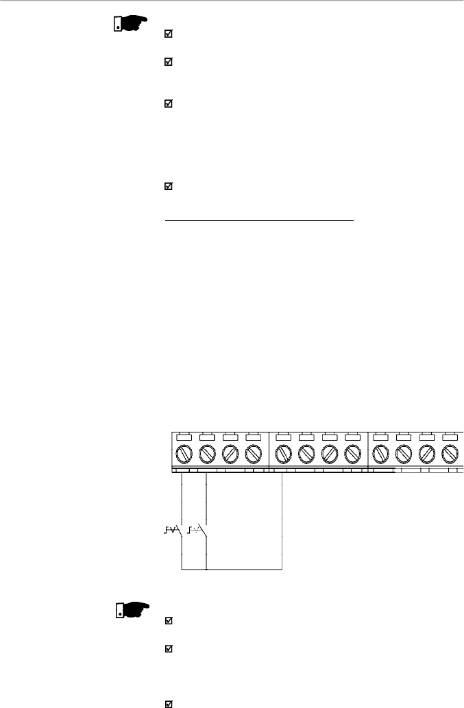
50
CHAPTER 3 - INSTALLATION
AND CONNECTION
NOTES!
S1
and
S2
are push buttons, start (NO contact) and stop
(NC
conta
ct), respectively.
The speed reference can be via analog input AI1 (as in
Connection 2), via keypad (HMI-CFW08-P), or via any other
source (as described in the parameters P221 and P222).
When a line fault occurs byusing this connection with the
motor running and the S1 and S2 switches are in original
position (S1 openned and S2 closed), at the moment the
voltage returns the inverter will not be enabled automatically,
it will only be enabled if the S1 switch were closed again (a
pulse at the Start digital input).
The Start/Stop function is described in chapter 6.
Connection 4 - FWD/REV Function
Parameter to be programmed:
Set DI1 to Forward Run : P263 = 8
Set DI2 to Reverse Run: P264 = 8
Make sure the inverter commands are via terminals, i.e.,
P229 = 1
to local mode or P230 = 1 to remote mode.
The figure 3.18 belowshows the inverter terminal connection
for this type of driving.
Figure 3.18
- XC1 wiring for connection 4
S1 open: Stop
S1 closed: Forward Run
S2 open: Stop
S2 closed: Reverse Run
DI1 - Forward Run
DI2 - Reverse Run
DI3 - Reset
COM
AI1
+10 V
AI2
AO1
NC
Common
NO
DI4 - No Function
S2
S1
1
2
3
4
5
6
7
8
9
10
11
12
NOTE!
For the correct operation of the connection 4, P266 must
be programmed as “Not Used”.
The speed reference can be via analog input AI1 (as in
connection 2), via keypad (HMI-CFW08-P), orvia anyother
source (refer to the description of parameters P221 and
P222).
When a line fault occurs, this connection with switch S1 or
switch S2 is closed, the motorwill be enabled automatically
as soon as the line is re-established.
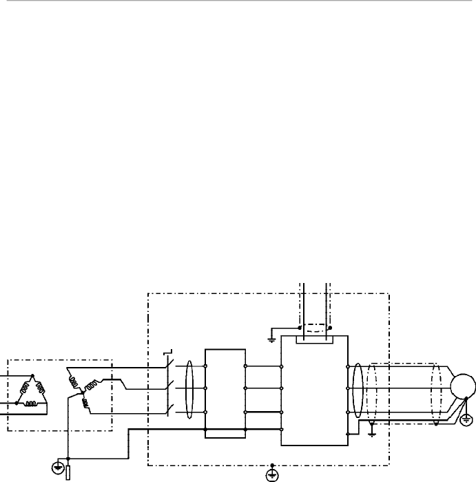
51
CHAPTER 3 - INSTALLATION
AND CONNECTION
3.3
EUROPEAN EMC
DIRECTIVE -
REQUIREMENTS
FOR CONFORMING
INST
ALLA
TIONS
The CFW-08 inverter series was designed considering safety
and EMC (Electromagnetic Compatibility) aspects.
The CFW-08 units do not have an intrinsic function until
connected with other components (e. g. a motor). Therefore,
the basic product is not CE marked for compliance with the
EMC Directive. The end user takes personal responsibility
for the EMC compliance of the whole installation. However,
when installed according to the recommendations described
in the manual of the product and including the recommended
filters and EMC measures the CFW-08 fulfill all requirements
of the EMC Directive (89/336/EEC) as defined by the
EMC
Product Standard forAdjustable Speed Electrical Power
Drive Systems EN61800-3.
Compliance of the CFW-08 series is based on the testing of
the representative models.ATechnical Construction File was
checked and approved by a Competent Body.
3.3.1
Installation
The figure 3.19 shows the EMC filters connection.
Figure 3.19
- EMC filters connection - general condition
Output
CM
Choke
Transformer
Ground Rod/Grid
or Building Steel
Structure
Metallic Cabinet (when required)
Protective Grounding - PE
Motor
PE
CFW-08
L2/N
L1/L
L3
E
PE
XC1
1 to 12
U
Input CM
Choke
Controling and Signal Wiring
V
W
PE
L1/L
L2/N
L3
External
Input RFI
Filter
L2
L1
L3
E
Obs.:
Single-phase input inverters use single-phase filters and only L1/L and L2/N are used.
Thefollowing items are required in order to have aconforming
installation:
1)
The motor cable must be armored, flexible armored or
installed inside a metallicconduit ortrunking with equivalent
attenuation. Ground the screen/metallic conduitat bothends
(inverterand motor).
2)Control and signal wiring must be shielded or installed inside
a metallic conduit or trunking with equivalentattenuation.
3) The inverter and the external filter must be mounted on a
common metallic back plate inclose proximity to one another.
Ensure that a good electrical connection is made between
the heatsink (inverter)
,
the
frame (external filter) and the back
plate.

52
CHAPTER 3 - INSTALLATION
AND CONNECTION
3.3.2
Emission and Immunity
Levels Description
4) The length of the wiring between filter and inverter must be
kept as short as possible.
5) The cables shielding
(motor and control)
must be solidly
connected to the common back plate, using a metal bracket.
6)Grounding asrecommended in this manual.
7)Use short
earthing cable to earth theexternal filter orinverter.
When an external filter is used, only use an earth cable at
filterinput-theinverterearthconnectionisdonebythemetallic
back plate.
8) Earth the back plate using a braid, as short as possible. Flat
conductors (e.g. braids or brackets) have lower impedance
athigh frequencies.
9) Use cable glands whenever possible.
EMC Phenomenon
Emission:
Conducted Emission (Mains Terminal
Disturbance Voltage - Frequency Band
150 kHz to 30 MHz)
Radiated Emission (Electromagnetic
Radiation Disturbance - Frequency
Band 30 MHz to 1000 MHz)
Immunity:
Electrostatic Discharge (ESD)
Fast Transient-burst
Conducted Radio-frequency
Common Mode
Surge
Radio-frequency Electromagnetic Field
Basic Standard
for Test Method
IEC/EN61800-3
IEC 61000-4-2
IEC 61000-4-4
IEC 61000-4-6
IEC 61000-4-5
IEC 61000-4-3
Level
“First environment”
(1)
unrestricted distribution
(3)
Category C1
, or;
“First environment”
(1)
restricted distribution
(4) (5)
Category C2, or;
“Second environment”
(2)
unrestricted distribution
(3) (6)
Category C3
“First environment”
(1)
, restricted distribution
(4) (5)
“Second environment”
(2)
, unrestricted distribution
(3)
6 kV contact discharge
4 kV/2.5 kHz (capacitive clamp) input cable
2 kV/5 kHz control cables; 2 kV/5 kHz (capacitive
clamp) motor cable; 1 kV/5 kHz (capacitive clamp)
external keypad cable
0.15 to 80 MHz; 10 V; 80 % AM (1 kHz) - motor,
control and remote keypad cable 1.2/50
s, 8/20
s
1 kV coupling line to line
2 kV coupling line to earth
80 to 1000 MHz; 10 V/m; 80 % AM (1 kHz)
Table 3.7
- Specification of the emission and immunity levels

53
CHAPTER 3 - INSTALLATION
AND CONNECTION
Notes:
(1)
First environment: includes domestic premises. It also
includes establishments directly connected without
intermediate transformers to a low-voltage power supply
network which supplies buildings used for domestic
purposes.
(2)
Second environment: includes all establishments other
than those directly connected to a low-voltage power
supplynetwork which supplies buildings used for domestic
purposes.
(3)
Unrestricted distribution: mode of sales distribution in
which the supply of equipment is not dependent on the
EMC competence of the customer or user for the
application of drives.
(4)
Restricted distribution: mode of sales distribution in which
the manufacturer restricts the supply of equipment to
suppliers, customers or users who separately or jointly
have technical competence in the EMC requirements of
the application of drives.
(source: these definitions were extracted from the product
standard IEC/EN61800-3 (1996) +A11 (2000))
(5)
For installation with inverters that complies Category C2
(first environment restricted distribution), note that this is
a product of restricted sales distribution class according
to IEC/EN61800-3 (1996) + A11 (2000). In a domestic
environment this productmaycause radio interference in
which case the user may be required to take adequated
measures.
(6)
For installation with inverters that complies Category C3
(second environment unrestricted distribution), refer to
table 3.7.
Note that this product is not intended to be used on a low-
voltage public network whichsupplies domestic premises.
If this product is used in networks that supply domestic
premises, there is the possibility of radio frequency
interference.

54
CHAPTER 3 - INSTALLATION
AND CONNECTION
3.3.3
Inverter Models
and Filters
Table 3.8 belowshows the inverter models and the respective
RFI filter and the EMCcategory. The description of each EMC
categories is given in item 3.3.2. The characteristics of the
footprint and external input RFI filters are given in item 3.3.4.
Id
Inverter Model
1
CFW080016S2024...FAZ
2
CFW080026S2024...FAZ
3
CFW080040S2024...FAZ
4
CFW080016B2024...FAZ
(single-phase input)
5
CFW080026B2024...FAZ
(single-phase input)
6
CFW080040B2024...FAZ
(single-phase input)
7
CFW080073B2024...FAZ
(single-phase input)
8
CFW080100B2024...FAZ
(single-phase input)
9
CFW080016S2024...
10
CFW080026S2024...
11
CFW080040S2024...
12
CFW080016B2024...
(single-phase input)
13
CFW080026B2024...
(single-phase input)
14
CFW080040B2024...
(single-phase input)
15
CFW080016B2024...
(three-phase input)
16
CFW080026B2024...
(three-phase input)
17
CFW080040B2024...
(three-phase input)
18
CFW080070T2024...
19
CFW080073B2024...
(single-phase input)
20
CFW080073B2024...
(three-phase input)
21
CFW080100B2024...
(single-phase input)
22
CFW080100B2024...
(three-phase input)
23
CFW080160T2024...
Input RFI Filter
FEX1-CFW08
(footprint filter)
Built-in Filter
FS6007-16-06 or
B84142-A30-R122
(external filter)
FN3258-7-45 or
B84143-B8-R110
(external filter)
FN3258-16-45 or
B84143-B16-R110
(external filter)
FS6007-25-08 or
B84142-A30-R122
(external filter)
FN3258-16-45 or
B84143-B25-R110
(external filter)
FS6007-36-08 or
B84142-A30-R122
(external filter)
FN3258-16-45 or
B84143-B25-R110
(external filter)
FN3258-30-47 or
B84143-B36-R110
(external filter)
Conducted Emission
Level
Category C2 or
Category C3
Category C1
Radiated Emission
Level
Category C3
Category C2
Table 3.8
- Inverter models list with filters and EMC category

55
CHAPTER 3 - INSTALLATION
AND CONNECTION
Id
Inverter Model
24
CFW080220T2024...
25
CFW080280T2024...
26
CFW080330T2024...
27
CFW080010T3848...FAZ
28
CFW080016T3848...FAZ
29
CFW080026T3848...FAZ
30
CFW080040T3848...FAZ
31
CFW080027T3848...FAZ
32
CFW080043T3848...FAZ
33
CFW080065T3848...FAZ
34
CFW080100T3848...FAZ
35
CFW080130T3848...FAZ
36
CFW080160T3848...FAZ
37
CFW080010T3848...
38
CFW080016T3848...
39
CFW080026T3848...
40
CFW080040T3848...
41
CFW080027T3848...
42
CFW080043T3848...
43
CFW080065T3848...
44
CFW080100T3848...
45
CFW080130T3848...
46
CFW080160T3848...
47
CFW080240T3848...
48
CFW080300T3848...
49
CFW080240T3848...FAZ
50
CFW080300T3848...FAZ
Input RFI Filter
B84143-B36-R110
(external filter)
B84143-B50-R110
(external filter)
B84143-B50-R110
(external filter)
FEX2-CFW08
(footprint filter)
Built-in filter
FN3258-7-45 or
B84143-B8-R110
(external filter)
FN3258-16-45 or
B84143-B25-R110
(external filter)
FN3258-16-45 or
B84143-G36-R110
(external filter)
FN3258-30-47 or
B84143-G36-R110
(external filter)
FN-3258-30-47 or
B84143-B50-R110
(external filter)
FN-3258-55-52 or
B84143-B50-R110
(external filter)
Built-in filter
Conducted Emission
Level
Category C1
Category C1
Category C2 or
Category C3
Category C1
Category C1
Category C1
Category C3
Radiated Emission
Level
Category C2
Category C2
Category C3
Category C2
Category C3
Category C3
Table 3.8
(cont.)
- Inverter models list with filters and EMC category
Observe the following notes forthe models presented on table
3.8:
1)
CategoryC1drives(forconductedemission)shallbemounted
inside a metallic cabinet so that the radiated emissions stay
belowthelimitsforresidentialapplications(“firstenvironment”)
and restricted distribution (refer to item 3.3.2).
Category C2 drives (for conducted emission) do not require
installationinside metalliccabinets. Exception: models 7 and
8, that need to be mounted inside a cabinet to pass in the
radiated emission test for second environment and
unrestricteddistribution(refertoitem
3.3.2). When a metallic

56
CHAPTER 3 - INSTALLATION
AND CONNECTION
cabinet is required, the maximum length of the remote
keypad cable is 3 m (9.84 ft). In this case, the remote
keypad, the control and signal wiring must be located inside
the cabinet (the remote keypad can be installed in the
cabinet front door, refer to items 8.6.1 and 8.8).
2)
The maximum switching frequency is 10 kHz. Exception:
5 kHz for models 27 up to 36 and models 47 to 450.
For Class A1 systems also refer to note 7.
3)
The maximum motor cable length is 50m (164 ft) for models
from 49 and 50, 20 m (65.6 ft)for models from 9 to 26, and
from 37 to 40,47 and 48, 10 m (32.8 ft) for models from 1 to
8, 27 to 30 and 41 to 46 and 5 m (16.4 ft) for models from
31 to 36. For Category C2 systems also refer to note 7.
4)
In models 31 to 34 (also refer to note 7), a CM choke at
inverter output is required:TOR1-CFW08, 1 turn. The toroid
is mounted inside the N1 kit that is provided with these
models. For installation refer to figure 3.19.
5)
In models from 41 to 46, a CM choke at filter input is
required: TOR2-CFW08, 3 turns. For installation refer to
figure 3.19.
6)
In models 41 to 44, it is required to use a shielded cable
between the external filterand the inverter.
7)
Category C2 drives were also tested using the limits of
conducted emission for industrial applications (“second
environment”) and unrestricted distribution, i.e., Category
C3 (refer to notes 2 and 3 in item 3.3.2 for definitions).
In this case:
-
The maximum cable length is 30 m (98.4 ft) for models
from 1 to 8, 35 and 36 and 20 m
(65.6 ft)
for models from
27 to 34;
-
The maximum switching frequencyis 10 kHz for models
31 to 34 and 5 kHz for models from 1 to 8, 27 to 30, 35
and 36;
- Models 31 to 34 do not require any CM choke at inverter
output (as stated in note 4).

57
CHAPTER 3 - INSTALLATION
AND CONNECTION
3.3.4
EMC Filters
Characteristics
Filter
WEG
Rated
Weight
Dimensions
Drawings
Manufacturer
P/N
Current
(kg/lb)
(Width x Height
x Depth in mm [in])
FEX1-CFW08
WEG
417118238
10 A
0.6/1.32
79x190x51
Figure 3.20
FEX2-CFW08
417118239
5 A
[3.11x7.48x2]
FS6007-16-06
0208.2072
16 A
0.9/1.98
85.5x119x57.6
Figure 3.21
[3.37x4.68x2.27]
FS6007-25-08
0208.2073
25 A
1.0/2.2
85.5x119x57.6
Figure 3.22
FS6007-36-08
0208.2074
36 A
1.0/2.2
[3.37x4.68x2.27]
FN3258-7-45
0208.2075
7 A
0.5/1.1
40x190x70
Schaffner
[1.57x7.48x2.76]
FN3258-16-45
0208.2076
16 A
0.8/1.76
45x250x70
[1.77x9.84x2.76]
Figure 3.23
FN3258-30-47
0208.2077
30 A
1.2/2.64
50x270x85
[1.97x10.63x3.35]
FN3258-55-52
0208.2078
55 A
1.8/3.97
85x250x90
[3.35x9.84x3.54]
TOR1-CFW08
417100895
-
0.08/0.18
e = 35 [1.38],
Figure 3.24
Thornton
h = 22 [0.87]
TOR2-CFW08
47100896
-
0.125/0.276
e = 52 [2.05],
Figure 3.25
h = 22 [0.87]
B84142-A16-R122
EPCOS
10951110
16 A
1.1/2.42
46,4x231x70
Figure 3.26
[1.83x9.09x2.76]
B84142-A30-R122
EPCOS
10951111
30 A
1.7/3.75
58x265x90
Figure 3.27
[2.28x10.43x3.54]
B84143-B16-R110
EPCOS
10951374
16 A
1.5/3.3
46x230x80
Figure 3.28
[1.81x9.05x3.15]
B84143-A16-R105
EPCOS
0208.2127
16 A
0.90/1.98
46,4x231x70
Figure 3.29
[1.83x9.09x2.76
B84143-B36-R110
EPCOS
10951375
36 A
3.2/7.05
56x280x150
Figure 3.30
[2.2x11.02x5.9]
B84143-A36-R105
EPCOS
0208.2129
36 A
1.75/3.86
58x265x90
Figure 3.31
[2.28x10.43x3.54]
B84143-B50-R110
EPCOS
10951401
50 A
3.7/8.16
56x330x150
Figure 3.32
[2.2x13x5.9]
B84143-A50-R105
EPCOS
0208.2130
50 A
1.75/3.86
58x265x90
Figure 3.33
[2.28x10.43x3.54]
B84143-B8-R110
EPCOS
10951398
8 A
1.5/3.3
46x230x80
Figure 3.34
[1.81x9.05x3.15]
B84143-B25-R110
EPCOS
10951404
25 A
2.7/5.95
56x280x150
Figure 3.35
[2.2x11.02x5.9]
B84143-G36-R110
EPCOS
10951437
36 A
2.8/6.17
56x280x150
Figure 3.36
[2.2x11.02x5.9]
Table 3.9
- EMC filters characteristics
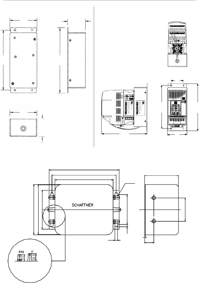
58
CHAPTER 3 - INSTALLATION
AND CONNECTION
Figure 3.21
- FS6007-16-06 external filter drawing
Figure 3.20 a) and b)
- FEX1-CFW08 and FEX2-CFW08 footprint filter drawing
Type /05
Fast-on terminal
6.3 x0.8 mm
119
109
98.5
6.3x0.8
57.6
15.6
1.2
4.4
85.5
84.5
66
51
3.7
40
Note:
figure dimensions are in mm.
Front View
Lateral Right
View
Bottom View
Terminal block for
flexible or rigid cable
of 4 mm
2
or AWG 10.
Max. torque: 0.8 Nm
a) Footprint Filter
Bottom View
Front View
Lateral Right View
b) Footprint Filter and Inverter
79
53
79
185
79
50
175
190
53
175
190
Note:
figure dimensions are in mm.
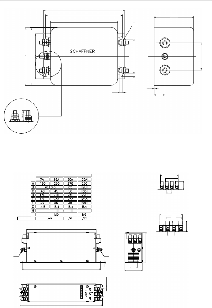
59
CHAPTER 3 - INSTALLATION
AND CONNECTION
Figure 3.23
- FN3258-7-45, FN3258-16-45, FN3258-30-47 and FN3258-55-52 external filters drawing
Figure 3.22
- FS6007-25-08 and FS6007-36-08 external filter drawing
Bolt type 08 = M4
119
113
98.5
15.6
1.2
4.4
85.5
84.5
66
51
3.7
40
P/N
E
M4
57.6
Type/45
Terminal block for 6 mm
2
solid cable,
4 mm
2
flexible cable AWG 12.
Top View
Side View
Connector
Rated Current
Type/47
Terminal block for 16 mm
2
solid wires, 10 mm
2
flexible wires AWG 8.
Mechanical Data
Front View
A
E
I
I
D
D
C
F
G
H
41,8
19,3
30,3
11,5
55,5
40,5
15
23,5
Line
L1 L2 L3
E
Note:
figure dimensions are in mm.
Note:
figure dimensions are in mm.
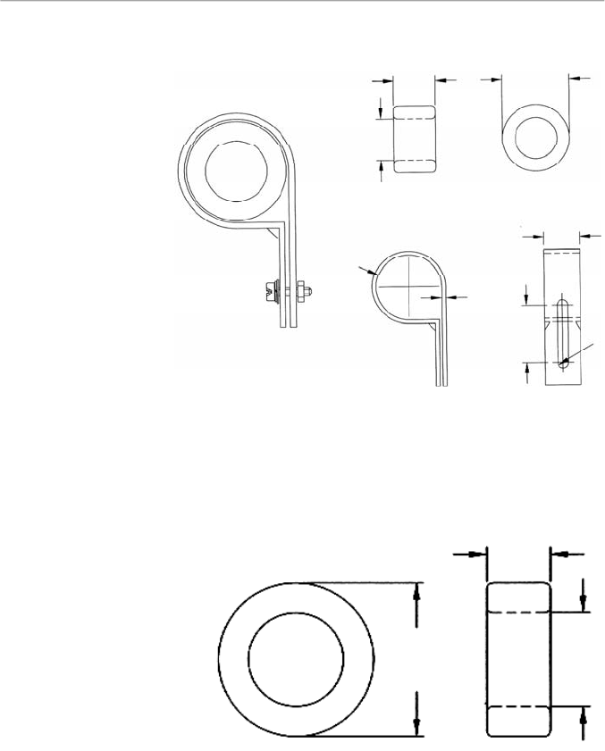
60
CHAPTER 3 - INSTALLATION
AND CONNECTION
Toroid: Thornton NT35/22/22-4100-IP12R
(WEG P/N 0208.2102)
Plastic clamp: HellermannTyton NXR-18
(WEG P/N 0504.0978)
Figure 3.24
- TOR1-CFW08 drawing
Toroid: Thornton NT52/32/20-4400-IP12E
(WEG P/N 0208.2103)
Figure 3.25
- TOR2-CFW08 drawing
22
22
35
1.5
33.3 to 38.1
19.3
5.8
30
20
52
32
Note:
figure dimensions are in mm.
Note:
figure dimensions are in mm.
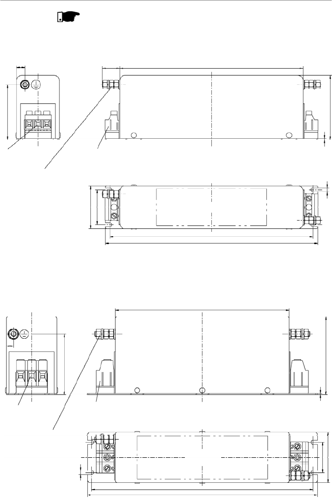
61
CHAPTER 3 - INSTALLATION
AND CONNECTION
NOTE!
The following filters drawings belong to Epcos. It is possible to get
further information about them in the Epcos website.
Terminals 4 mm
2
Tightening torque of screw 0,5 - 0,6 Nm
Not used for
connection
PE M5
Tightening torque 2,8 ± 0,1 Nm
Note:
figure dimensions
are in mm.
Marking
Figure 3.26
- External filter drawing B84142-A16-R122
Figure 3.27
- External filter drawing B84142-A30-R122
Not used for
connection
Terminals 10 mm
2
Tightening torque of screw 1,2 -1,5
Nm
PE M6x24
Tightening torque
3 ± 0,15 Nm
Note:
figure dimensions
are in mm.
Marking
199,5
19
70
1,5
4,5
60
9
46,4
38
221
231
200
90
1,5
70
8
58
35
255
265
4,5
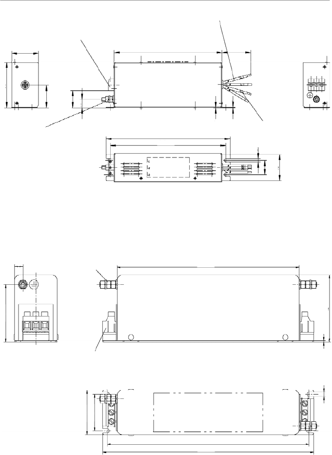
62
CHAPTER 3 - INSTALLATION
AND CONNECTION
Figure 3.29
- External filter drawing B84143-A16-R105
PE M5x19
Tightening torque 2 ± 0,1 Nm
Terminals 4 mm
2
Tightening torque of screw 0,5 - 0,6 Nm
Note:
figure dimensions are in mm.
Marking
9
60
199,5
70
1,5
38
46,4
231
221
4,5
Figure 3.28
- External filter drawing B84143-B16-R110
Terminals 4 mm
2
Tightening torque of screw 0,7 ± 0,1 Nm
Litz wire 2,5 mm
2
Earth connector M6 x 25
Tightening torque 4,8 ± 0,2 Nm
Marking
Note:
figure dimensions are in mm.
Marking
230
215 ±0,5
300 ±10
50
80
40
(31)
15
0,5
6,5
25 ±0,3
46
200
1
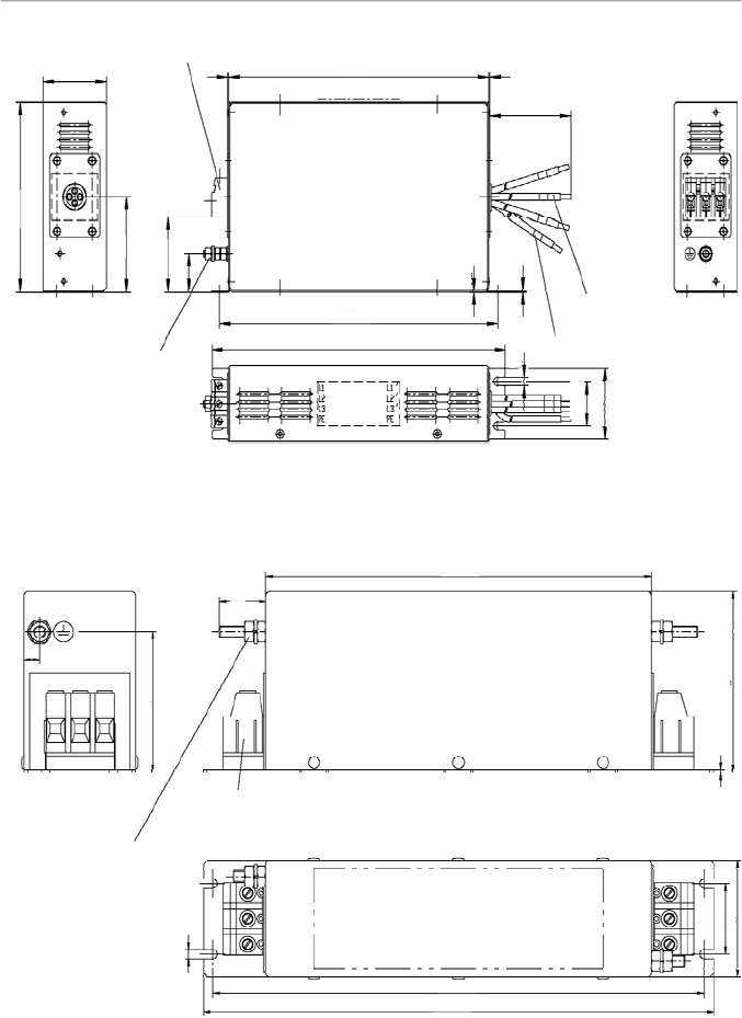
63
CHAPTER 3 - INSTALLATION
AND CONNECTION
Figure 3.30
- External filter drawing B84143-B36-R110
Note:
figure dimensions are in mm.
Figure 3.31
- External filter drawing B84143-A36-R105
Earth connector M6
Tightening torque 4,8 ± 0,2 Nm
Terminals 10 mm
2
Tightening torque of screw 1,2 - 1,5 Nm
Marking
Note:
figure dimensions are in mm.
70
35
58
255
265
200
90
1,5
4,5
24
8
Terminals 6 mm
2
Tightening torque 1,5 - 1,8 Nm
PE M6x24
Tightening torque
3 ± 0,15 Nm
Litz wire 4 mm
2
Marking
Marking
Line
Load
150
60
75
60
30
248
280
265 ±0,5
0,5
400 ±10
6,5
35 ±0,3
56
1
1
1
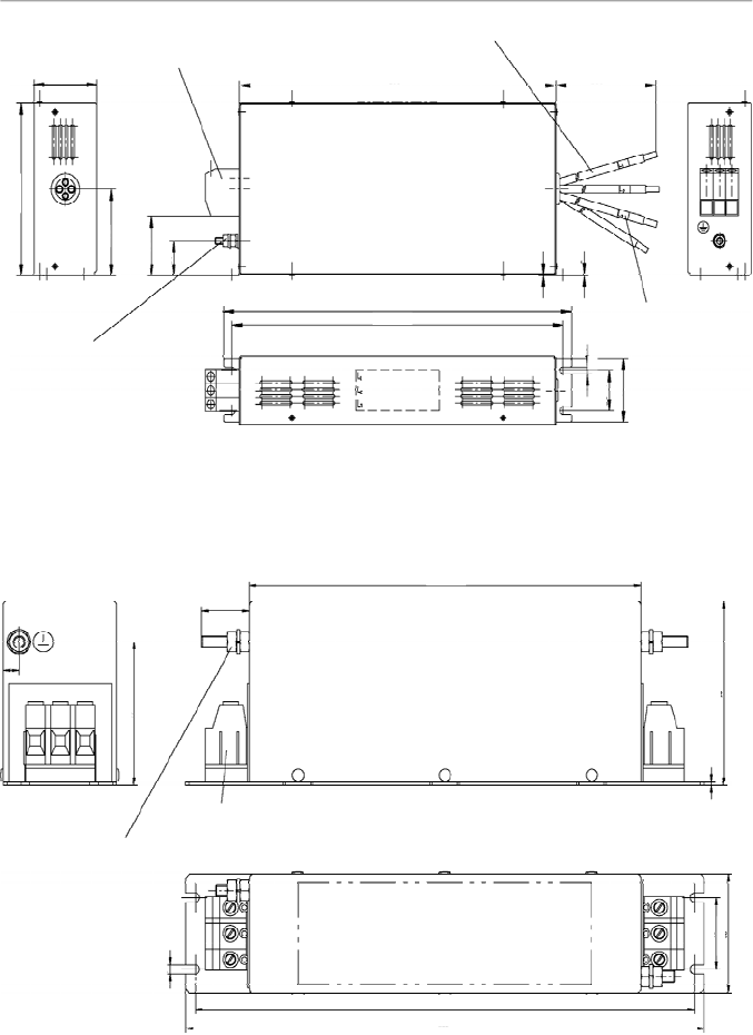
64
CHAPTER 3 - INSTALLATION
AND CONNECTION
Figure 3.33
- External filter drawing B84143-A50-R105
Terminals 10 mm
2
Tightening torque of screw 1,2 - 1,5 Nm
Earth connector M6
Tightening torque 4,8 ± 0,2 Nm
Marking
Note:
figure dimensions are in mm.
70
35
58
255
265
200
90
1,5
4,5
24
8
Figure 3.32
- External filter drawing B84143-B50-R110
Terminals 16 mm
2
Tightening torque of screw 1,65 ± 0,15 Nm
Litz wire 10 mm
2
Earth connector M6x25
Tightening torque
4,8 ± 0,2 Nm
Marking
Note:
figure dimensions are in mm.
6,5
35 ±0,3
56
60
150
75
30
(52)
330
315 ±0,5
300
500 ±10
0,5
1
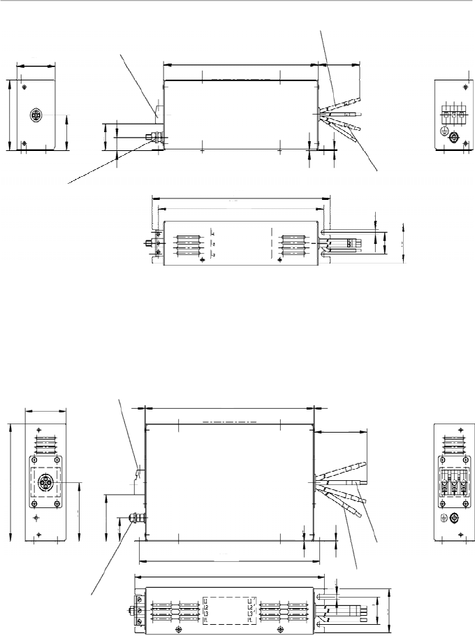
65
CHAPTER 3 - INSTALLATION
AND CONNECTION
Figure 3.34
- External filter drawing B84143-B8-R110
Terminals 4 mm
2
Tightening torque of screw 0,7 ± 0,1 Nm
Litz wire 1,5 mm
2
Earth connector M6x25
Tightening torque 4,8 ± 0,2 Nm
Note:
figure dimensions are in mm.
Marking
Marking
50
80
40
(31)
15
230
215 ±0,5
200
300 ±10
0,5
6,5
25 ±0,3
46
Figure 3.35
- External filter drawing B84143-B25-R110
Terminals 6 mm
2
Tightening torque 1,5 - 1,8 Nm
PE M6x24
Tightening torque
3 ± 0,15 Nm
Litz wire 4 mm
2
Marking
Note:
figure dimensions are in mm.
Marking
Line
Load
150
60
75
60
30
248
400 ±10
35 ±0,3
56
265 ±0,5
280
0,5
6,5
1
1
1
1
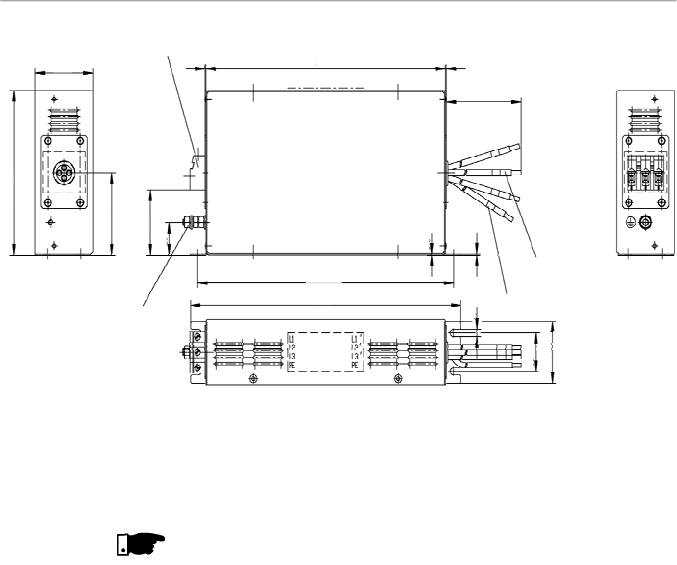
66
CHAPTER 3 - INSTALLATION
AND CONNECTION
NOTE!
The declaration of conformity CE is available on the website
www.weg.net or on the CD, which comes with the products.
Figure 3.36
- External filter drawing B84143-G36-R110
Terminals 6 mm
2
Tightening torque 1,5 - 1,8 Nm
PE M6x24
Tightening torque
3 ± 0,15 Nm
Litz wire 6 mm
2
Marking
Note:
figure dimensions are in mm.
Marking
Load
Line
150
60
75
60
30
248
400 ±10
35 ±0,3
56
265 ±0,5
280
0,5
1
1
1
6,5
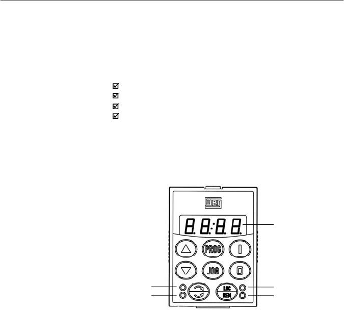
67
KEYPAD (HMI) OPERATION
This chapter describes the standard Human Machine
Interface (HMI) of theinverter(HMI-CFW08-P) and the manner
to use it, presenting the following information:
General keypad description.
Use of the keypad.
Parameter programming and reading.
Description of the status indications and signalizations.
The standard CFW-08 keypad has a LED displaywith 4 digits
of 7 segments, 4 status LEDs and 8 keys. Figure 4.1 shows
the front view of the keypad and indicates the position of the
display and the status LEDs.
4.1
KEYPAD (HMI)
DESCRIPTION
LED Display
LED "Local"
LED"Remote"
LED "FWD"
LED "REV"
Figure 4.1
- CFW-08 standard keypad
Functions of the LED display:
The LED displayshows the fault codes and drive status (refer
to Quick Parameter Reference, Fault Messages), the
parameter number and its value. The unit display(rightmost)
indicates the unit of some variables [U = volts,A = Ampères,
°C = Celsius degrees].
Functions of the “Local” and “Remote” LEDs:
Inverter in Local mode:
Green LED ON and red LED OFF.
Inverter in Remote mode:
Green LED OFF and red LED ON.
Functions of the FWD/REV LEDs - Direction of rotation
Refer to figure 4.2.
CHAPTER 4

68
CHAPTER 4 - KEYPAD (HMI) OPERATION
Figure 4.2
- Direction of rotation (FWD/REV) LEDs
OFF
ON
Flashing
Basic functions of the keys:
Starts the inverter via acceleration ramp.
Stops (disables) the inverter via deceleration ramp.
Also resets inverter after a fault has occurred.
Toggles the LED display between parameter number and its
value
(
number/value).
Increases the frequency, the parameter number or the
parameter value.
Decreases the frequency, the parameter number or the
parameter value.
Reverses the direction of motor rotation between Forward/
Reverse
Toggles between the LOCAL and REMOTE modes of
operation.
Performs the JOG function when pressed. AnyDI programmed
for General Enable (if any) must be closed to enable the JOG
function.
ThekeypadisusedforprogrammingandoperatingtheCFW-08,
allowingthefollowingfunctions:
Indication of the inverter status and operation variables.
Fault indication and diagnostics.
Viewing and programming parameters.
4.2
USE OF THE
KEYPAD (HMI)
FWD/REV
Control
Selection
FWD / REV
HMI LED
Situation
Forward
Reverse
Forward
t
t
t
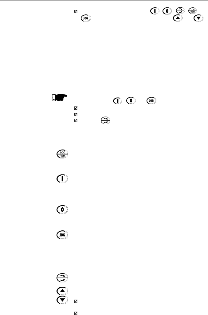
69
CHAPTER 4 - KEYPAD (HMI) OPERATION
4.2.1
Keypad Operation
All functions relating to the CFW-08 operation (Start/Stop,
Direction of Rotation, JOG, Increment/Decrement, Speed
(Frequency) Reference, and selection of Local/Remote mode)
can be performed through the HMI selection.
For factory default programming of the inverter, all keypad keys
are enabled when the Local mode has been selected.
These same functions can be performed through digital and
analog inputs.Thus you must program the parameters related
to these corresponding inputs.
NOTE!
The control keys , and are only enabled if:
P229 = 0 for Local mode operation.
P230 = 0 for Remote mode operation.
The key depends of the parameters above and if:
P231 = 2.
Keypad keys operation description:
When enabled (P220 = 2 or 3), selects the control input and the
speed reference (speed) source, toggling between Local
and
Remote Mode.
When pressed,starts the motoraccording to acceleration ramp
up to the speed (frequency)reference. The function is similar
to that performed through digital input Start/Stop, when it is
closed (enabled) and maintained enabled.
Disables the inverter via deceleration ramp.The Function is
similar to that performed through digital input Start/Stop, when
it is open (disabled) and maintained disabled.
When the JOG key is pressed, it accelerates the motor
according to the acceleration ramp up to the JOG speed
programmed in P122.
This key is only enabled when the inverter digital input,
programmed to Start/Stop (if any) is open and the digital
input programmed to General Enable (if any) is closed.
When enabled, reverses the motor direction of rotation.
Motor speed (frequency) setting: these keys are enabled for
speed setting only when:
The speed reference source is the keypad (P221 = 0 for
Local Mode and/or P222 = 0 for Remote Mode).
The following parameter content is displayed: P002, P005
or P121.
Operation of the inverter (keys , , , and
) and speed reference setting (keys and ).
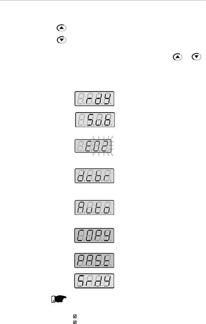
70
CHAPTER 4 - KEYPAD (HMI) OPERATION
Inverter is Ready to be started.
Line voltage is too low for inverter
operation (undervoltage condition).
Inver
ter is in a fault condition. Fault code
is flashing on the display. In the example
there is the fault code E02 (refer to
chapter 7).
Inverter is applying a DC current on the
motor (DC braking)
according to the
values programmed at P300, P301 and
P302 (refer to chapter 6).
Inverter is running self-tuning routine to
identify motor parameters automatically.
This operation is controlled by P408
(refer to chapter 6).
COPY function (available onlyat the HMI–
CFW08-RS), it copies the inverter
programminginto the HMI.
COPY function (available onlyat the HMI–
CFW08-RS), it copies the programming
from the HMI into the inverter.
Inverter in the Sleep rdymode.
NOTE!
The display also flashes in the following conditions, besides
the fault conditions:
Trying to change a parameter value when it is not allowed.
Inverter in overload condition (refer to chapter 7).
4.2.2
Inverter Status
Parameter P121 storesthe speed
(frequency)
referenceset by
the keys:
When pressed, it increases the speed (frequency)reference.
When pressed, it decreases the speed (frequency) reference.
Reference Backup:
The last frequency reference set by the keys and
is
stored when inverter is stopped or the AC power is removed,
provided P120 = 1 (reference backup active is the
factory
default).To change the frequencyreference before starting the
inverter,the value of the parameter P121 must be changed.
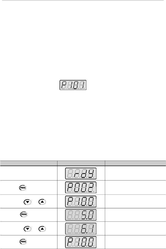
71
CHAPTER 4 - KEYPAD (HMI) OPERATION
4.2.4
Parameter Viewing and
Programming
All CFW-08 settings are made through parameters. The
parameter are shown on the display by the letter
P
followed
by a number:
Example (P101):
101 = Parameter Number
Each parameter is associated with a numerical value
(parameter value), that corresponds to the selected option
among the available ones for this parameter.
The parametervalues define the inverter programming orthe
value of a variable (e.g.: current, frequency, voltage).For in-
verter programming you should change the parameter
content(s).
It is necessary to set P000 = 5 before to change a parameter
value. Otherwise you can only read the parametervalues, but
not reprogram them
.
For more details, refer to the parameter
P000 description in chapter 6.
ACTION
HMI DISPLAY
DESCRIPTION
Turn ON the inverter
Press the key
Use the keys
and
Press the key
Use the keys
and
Press the key
Inverter is ready to be started
Select the desired parameter
Numerical value associated with the
parameter
(4)
Set the new desired value
(1) (4)
(1) (2) (3)
Parameters P002 to P099 are reserved for thedisplay of read-
onlyvalues.
The factory default displaywhen power is applied to the inverter
is P002 (frequency proportional value in V/F control mode
(P202 = 0 or 1) and motor speed in rpm in vector control mode
(P202 = 2)).
ParameterP205 defines the initial monitoring parameter, i.e.,
defines the read-only variable that will be displayed when the
inverter is powered up. For further information refer to P205
description in chapter 6.
4.2.3
Read-Only Parameters

72
CHAPTER 4 - KEYPAD (HMI) OPERATION
(3)
If the last programmed value in the parameter is not
functionallycompatible withother parameter values already
programmed, E24 = Programming Error, will be displayed.
Example of programming error:
Programming of two digital inputs (DI) with the same
function. Refer to table 4.1 for list of programming errors
that can generate an E24 Programming Error.
(4)
To allowthe reprogramming of any parameter value (except
for P000 and P121) it is required to set P000 = 5.
Otherwise you can onlyread the parameter values, but not
reprogram them
.
For more details, refer to the parameter
P000 description in chapter 6.
NOTE!
(1)
For parametersthatcanbe changed with themotor running,
the inverter will use the new value immediatelyafter it has
been set. For parameters that can be changed only with
motor stopped, the inverter will use thisnewvalue onlyafter
the key is pressed.
(2)
By pressing the key after the reprogramming, the
new programmed value will be stored automatically and
will remain stored until a new value is programmed.

73
CHAPTER 4 - KEYPAD (HMI) OPERATION
NOTE!
It is possible that during programming occurs the error E24
caused by incompatibilitybetween some parameters already
programmed.
In this case do not stop with the parameter setting. If at the
end of the parameter setting does not disappear, check the
table of incompatibilities (table 4.1).
Table 4.1
- Incompatibility of parameters - E24
JOG
P265
=
3 and other(s) DI(s)
Start
-
Stop or FWD and REV or ON and OFF
P266
=
3 and other(s) DI(s)
Start
-
Stop or FWD and REV or ON and OFF
P267
=
3 and other(s) DI(s)
Start
-
Stop or FWD and REV or ON and OFF
P268
=
3 and other(s) DI(s)
Start
-
Stop
or FWD and REV or ON and OFF
Local/Remote
Two or more parameters between P264, P265, P266, P267 and P268 equal to 1
(LOC/REM)
Disables Flying
Start
P265
=
13 and P266
=
13 or
P267
=
13 or
P268
=
13
Reset
P265
=
10 and
P2
66
=
10 or
P267
=
10 or
P268
=
1
0
On/Off
P263
=
14 and
P2
64
14 or
P263
14 and
P2
64
=
14
Direction of
R
otation
Two or more parameters P264, P265, P266, P267 and P268 = 0 (
D
irection of
R
otation)
FWD/REV
P263
=
8 and P264
8 and P264
13
P263
=
13 and P264
8 and P264
13
P263
8 and P263
13 and P264
=
8
P263
=
8 or 13 and P264
=
8 or 13 and P265
=
0 or P266
=
0 or P267
=
0 or P268
=
0
P263
=
8 or 13 and P264
=
8 or 13 and P231
2
Multispeed
P221
=
6 or P222
=
6 and P264
7 and P265
7 and P266
7 and P267
7 and P268
7
P221
6 and P222
6 and P264
=
7 or P265
=
7 or P266
=
7 or P267
=
7 and P268
=
7
Electronic
Potentiometer
P221 = 4 or P222 = 4 and P265
5 or 16 and P266
5 or 16 and P267
5 or 16 and
P268
5 or 16
P221
4 or P222
4 and P265 = 5 or 16 or
P266 = 5 or 16 or P267 = 5 or 16 or
P268 = 5 or 16
P265
=
5 or 16 and P266
5 or 16 and P268
5 or 16
P266
=
5 or 16 and P265
5 or 16 and P267
5 or 16
P267
=
5 or 16 and P266
5 or 16 and P268
5 or 16
P268
=
5 or 16 and P265
5 or 16 and P267
5 or 16
Rated
C
urrent
P295 incompatible with the inverter model
DC Braking and
Ride
-
through
P300
0 and P310 = 2 or 3
PID
P203
=
1 and P221
=
1,4,5,6,7 or 8 or P222
=
1,4,5,6,7 or 8
Ramp 2
P265
=
6 and P266
=
6 or P265
=
6 and P267
=
6 or P265
=
6
and P268
=
6
P266
=
6 and P267
=
6 or P267
=
6 and P268
=
6 or P266
=
6 and P268
=
6
P265
=
6 or P266
=
6 or P267
=
6 or P268
=
6 and P263
=
13
P265
=
6 or P266
=
6 or P267
=
6 or P268
=
6 and P264
=
13
P265
=
6 or P266
=
6 or P267
=
6 or P268
=
6 and P2
63
=
13
P265
=
6 or P266
=
6 or P267
=
6 or P268
=
6 and P264
=
13
Model
P221
=
2,3,7 or 8 and standard inverter
P221
=
2,3,7 or 8 and standard inverter
Analog
Input
P221
=
1 or P222
=
1 and P235
=
2, 3, 4 or 5
P221 or P222
=
2 or 3 and P239
=
2, 3, 4
or 5
Programming Error – E24

74
5.1
PRE-POWER
CHECKS
This chapter provides the following information:
How to check and prepare the inverter before power-up.
How to power-up and check for proper operation.
How to operate the inverter when it is installed according
to the typical connections (refer to item 3.2 - Electrical
Installation).
The inverter shall be installed according to Chapter 3 -
Installation andConnection. If the drive project is different from
the typical suggested connections, follow the procedures
below.
DANGER!
Always disconnect the AC input power before making any
connections.
1)
Check all connections
Check if the power, grounding and control connections are
correct and well tightened.
2)
Check the motor
Check all motor connections and verify if its voltage and
current match the inverter specifications.
3)
Uncouple the load from the motor
If the motor can not be uncoupled, make sure that the
direction of rotation (FWD/REV) can not cause damage to
the machine.
Afterthe inverter has been checked,AC powercan be applied:
1)
Check the power supply
Measure the line voltage and check if it is within the
specified range (rated voltage: -15 % / +10 %).
2)
Power-up the AC input
Close the input circuit breaker or disconnect switch.
3)
Check if the power-up has been successful
- Inverter with keypad (HMI-CFW08-P or HMI-CFW08-RS) or
HMI-CFW08-RP
The keypad display will show:
5.2
INITIAL
POWER-UP
START-UP
CHAPTER 5

75
CHAPTER 5 - START-UP
5.3
START-UP
This section describes start-up procedures when operating
via the keypad (HMI). Two types of control will be considered:
V/F and Vector Control:
The V/F control is recommended in the following cases:
Several motors driven bythe same inverter.
Rated current of the motor is lowerthan 1/3 of rated inverter
current.
For test purposes, inverter is start-up without load.
The V/F control can also be used in applications that do not
require fast dynamic responses, accurate speed regulations
or high starting torque (speed error will be a function of the
motor slip); when you program parameter P138 - Slip
Compensation - you can obtain a speed accuracy of 1 %.
For the most applications, we recommend the vector
control
mode, that permits a higher speed control accuracy (typical
0
.
5 %),
higher starting
torque
and a faster dynamic response.
The necessary adjustments for the operation of the vector
control are performed automatically. In this case the motor shall
be connected to the CFW-08.
This means that the inverter is ready (rdy = ready) to be
operated.
- Inverter with dummy panel (TCL-CFW08 or TCR-
CFW08).
The LEDs ON (green) and ERROR (red) are ON.
Inverter runs some self-diagnosis routines.If no problems are
found the LED ERROR (red) turns OFF. This means that the
inverter is now ready to be operated.
The four LEDs of the keypad remains ONduring this procedure.
Inverter runs some self-diagnosis routines.If no problems are
found, the display shows:
DANGER!
Even after theAC power supplyhas been disconnected, high
voltages may be still present.
Wait at least
10 minut
e
s
after
powering down to allow full discharge of the capacitors.
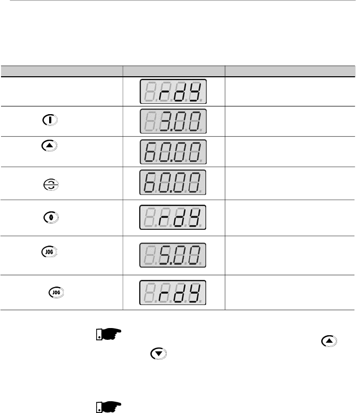
76
CHAPTER 5 - START-UP
NOTE!
The lastfrequencyreference (speed) value set via the
and keys is saved.
If you wishto change this valuebefore inverter enabling,change
parameter P121 - Keypad Reference.
NOTES!
(1)
If the direction of rotation of the motoris not correct, switchoff
the inverter. Wait at least for 10 minutes to allow complete
capacitor discharge and then swap any two wires at the mo-
tor output.
(2)
If the acceleration current becomes too high, mainly at low
frequencies,setthetorqueboost(IxRcompensation)atP136.
Increase/decrease the content of P136 gradually until you
obtain an operation with constant current over the entire
frequencyrange.
For the case above,refer to parameter descriptioninchapter
6.
(3)
If E01 fault occurs during deceleration, increase the
deceleration time at P101 / P103.
ACTION
HMI DISPLAY
DESCRIPTION
Power-up the inverter
Press the key
Press the key and hold it
depressed until 60 Hz is reached
Press the key
Press
the key
Press
the
key and hold it
depressed
Release the key
Inverter is ready to be operated
Motor accelerates from 0 Hzto 3 Hz
(*)
(
minimum
frequency), intheforward(CW)
direction of rotation
(1)
Motor accelerates up to 60 Hz
(**)
(2)
Motor decelerates
(3)
down to 0 rpm and
then reverses the direction of rotation
CW
CCW accelerating back to 60 Hz
Motor decelerates down to 0 rpm
Motor accelerates up to JOG frequency
given by P122.
Ex:
P122 = 5.00 Hz
Reverse (CCW)
Motor decelerates down to 0 rpm
5.3.1
Start-up -
Operation via Keypad
(HMI) - Type of Control:
Linear V/F (P202 = 0)
The sequence belowis valid for the connection 1 (refer to item
3.2.6). Inverter must be already installed and powered up
according to chapter 3 and item 5.2.
Connections according to figure 3.6.
(*)
90 rpm for 4 pole motor.
(**)
1800 rpm for 4 pole motor.
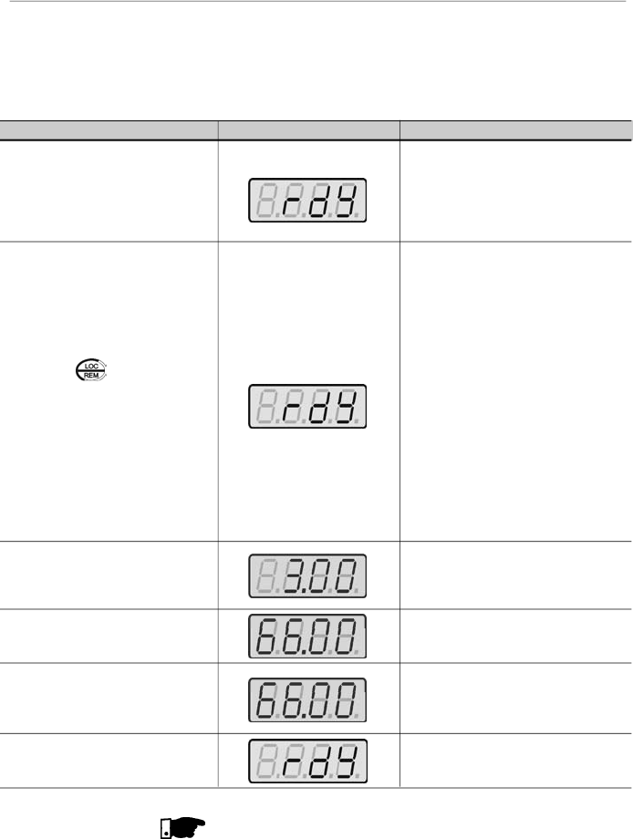
77
CHAPTER 5 - START-UP
5.3.2
Start-up -
Operation via Terminals -
Control Mode:
Linear V/F (P202 = 0)
Connections are according to figures 3.6 and 3.16.
ACTION
HMI DISPLAY
DESCRIPTION
Refer to figure 3.16
Switch
S1 (
FWD / REV
)
=
open
Switch S2 (Reset) = open
Switch S3 (Start/Stop) = open
Poten
tiometer
R1 (Ref.)
=
totally CCW
Power-up inverter
Press the key.
This procedure is not necessary when
inverters were delivered dummy panel,
since it will be automatically in remote
mode
Close
S3
– Start/Stop
Turn potentiometer totally CW
Close
S1
– FWD / REV
Open
S3
– Start / Stop
Inverter is ready to be operated
L
ocal LED
switches OFF and remote
LED switches ON
.
Control and
Reference are switched to remote
(via
terminals
)
Note:
To maintain inverter permanently
in remote mode, set
P220
=
1.
If the inverter is switched off and
afterwards switched on, it
will
now operate in local mode
because P220 = 2 (factory
setting). This setting means
that the local/remote selection
source is via keypad and the
default mode (that is the mode
when the inverter is switched
on) is local. For further
information refer to the
description of P220 in chapter 6
Motor accelerates from 0 Hz to 3 Hz
(*)
(minimum frequency), CW direction
(1)
The frequencyreference is given by the
potentiometer R1
Motor accelerates up to the maximum
frequency (P134 = 66 Hz)
(2)
Motor decelerates
(3)
down to 0 rpm (0
Hz), reverses the direction of rotation
(FWD/REV) accelerating back up to the
maximum frequency (P134 = 66 Hz)
Motor decelerates
(3)
down to 0 rpm
NOTES!
(1)
If the direction of rotation of the motoris not correct, switch
off the inverter. Wait 10 minutes to allow a complete
capacitor discharge and swap any two wires at the motor
output
.
(2)
If the acceleration current becomes toohigh, mainly at low
frequencies, set the torque boost (IxR Compensation) at
P136.
(*)
90 rpm for 4-pole motor.
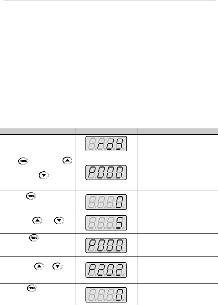
78
CHAPTER 5 - START-UP
5.3.3
Start-up -
Operation via Keypad -
Control Mode:
Vector (P202 = 2)
ACTION
HMI DISPLAY
DESCRIPTION
Power-up inverter
Press key. Press the
key until P000
is reached. You can
also use the key to reach
the paramater P000
Press the key to enter into
the
parameter P000
programming
mode
Use the keys and to
set the passoword value
(P000 = 5)
Press the key to save the
selected option and to exit the
programming mode
Press the key or until
P202
is reached
Press the key to enter into
the
parameter P202.
programming
mode
Inverter is ready to be operated
P000 = access for changing parameters
Enter the programming mode
P000 = 5: permits parameter changing
Exit the programming mode
This parameter defines the control type
0 = V/F Linear
1 = V/F Quadratic
2 = Vector
Enter the programming mode
Increase/decrease the content of P136 gradually until you
obtain an operation with constant current over the entire
frequencyrange.
For the case above, refer to parameter description in
chapter 6.
(3)
If E01 fault occurs during deceleration, increase the
deceleration time at P101 / P103.
The sequence below is based on the following inverter and
motor example:
Inverter:
CFW080040S2024ESZ
Motor:
WEG-IP55
Power: 0.75 HP/0.55 kW;
Frame size: 71; RPM: 1720; Number of Poles: IV;
Power Factor (cos
): 0.70;
Efficiency (
): 71 %;
Rated Current at 220 V: 2.90A;
Frequency: 60 Hz.
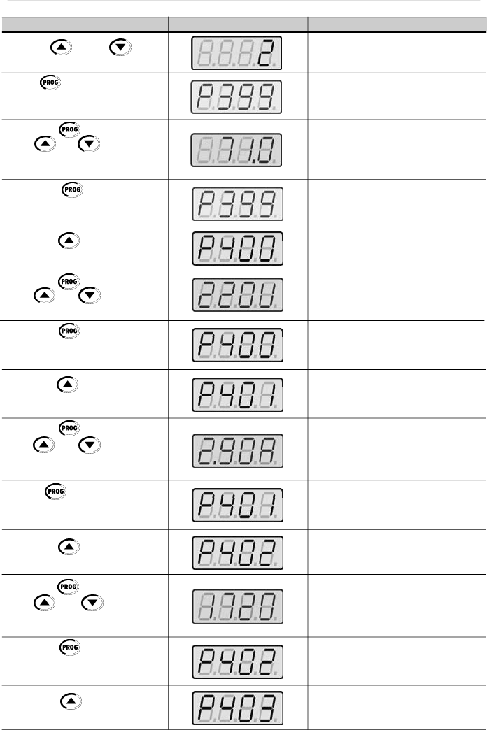
79
CHAPTER 5 - START-UP
ACTION
HMI DISPLAY
DESCRIPTION
Use the and keys
to select the control type
Press
to save the selected
option and to start the tuning routine
after changing to Vector Control mode
Press the key and use the
keys and to set the
correct rated motor efficiency
(
in
this case
71
%)
Press the key to save the
selected option and to exit the
programming mode
Press the key to go to the
next parameter
Press the key and use the
keys and to set the
correct rated motor voltage
Press the key to save the
selected option and to exit the
programming mode
Press the key to go to the
next parameter
Press the key and use the
keys and to set the
correct rated motor current (in this
case 2.90 A)
Press key to save the
selected option and to exit the
programming mode
Press the to go to the next
parameter
Press the key and use the
keys and to set the
correct motor speed (in this case
1720 rpm)
Press the key to save the
selected option and exit the
programming mode
Press the key to go to the
next parameter
P202 = 2: Vector
Motor efficiency:
50 to 99.9 %
Set motor efficiency:
71 %
Exit the programming mode
Rated motor voltage range:
0 to 600 V
Set rated motor voltage:
220 V (the default value is maintained)
(2)
Exit the programming mode
Rated motor current range:
0.3 x I
nom
to 1.3 x I
nom
Set rated motor current: 2.90 A
Exit the programming mode
Rated motor rpm range:
0 to 9999 rpm
Programmed rated motor rpm:
1720 rpm
Exit the programming mode
Rated motor frequency:
0 to F
max
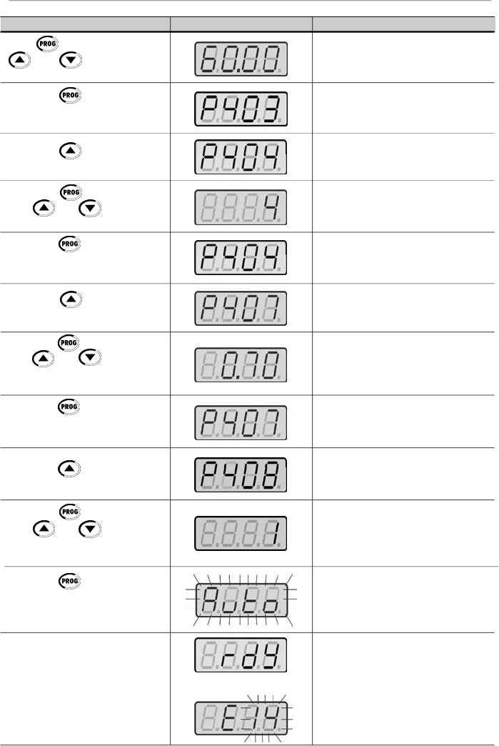
80
CHAPTER 5 - START-UP
ACTION
HMI DISPLAY
DESCRIPTION
Press
and use the keys
and
to set the correct
value for the motor frequency
Press the key to save the
selected option and exit the
programming mode
Press the key to go to the
next parameter
Press the key and use the
keys and to set the
correct motor power
Press the key to save the
selected option and exit the
programming mode
Press the key to go to the
next parameter
Press the key and use the
keys and to set the
correct motor power factor (in this
case 0.70)
Press the key to save the
selected option and exit the
programming mode
Press the key to go to the
next parameter
Press the key and use the
keys and to authorize or
not the start of the parameter
estimate
Press the key to start the
self-tuning routine. While the self-
tuning routine is running, the display
shows "Auto”
The running of the Self-Tuning
Routine can last until 2 minutes and
after ending display will show “rdy”
(ready), when the motor parameter
were acquired with success.
Otherwise the fault “E14” is shown.
In this case refer to note
(1)
below
Set rated motor frequency:
60 Hz(the default value is maintained)
(2)
Exit the programming mode
Rated motor power range:
0 to 15 (each value represents a power
value)
Selected rated motor power:
4 = 0.75 HP / 0.55 kW
Exit the programming mode
Motor power factor range:
0.5 to 0.99
Set motor power factor:
0.70
Exit the programming mode
Parameter estimation?
0 = No
1 = Yes
1 = Yes
Self-tuning is running
Inverterfinished the self-tuning routine
and is ready for operation,
or
Running of self-tuning routine has not
been realized with success
(1)
or
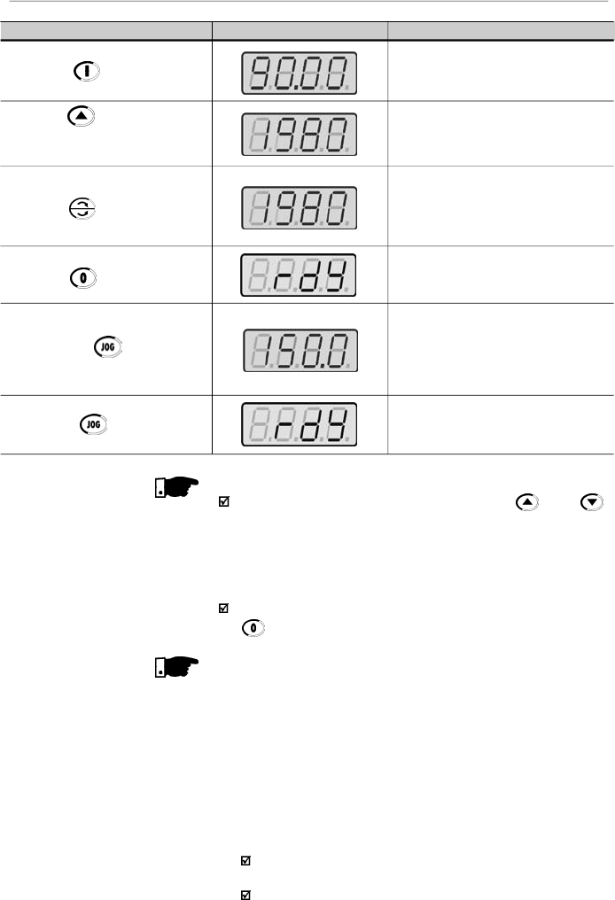
81
CHAPTER 5 - START-UP
NOTE!
The last speed reference value set via key and
keys
is saved.
If you wish to changethis value before enabling of inverter,
change the value of the parameter P121 - Keypad
Reference.
The self-tuning routine can be cancelled by pressing the
key.
NOTES!
(1)
If during the running of the Self-Tuning Routine the display
shows E14,
this means that the motor parameters were
not acquired correctly by the inverter. The most common
reason for this fault may be that the motor has not been
coupled to the inverter output. However motors with very
lower currents than the used inverter, or incorrect motor
connection may also cause the fault E14. In this case,
operate the inverter in V/F mode (P202 = 0). When the
motor is not connected and the fault condition
E14
is
indicated, proceed as follows:
Switch off the inverter. Wait at least 10 minutes to allow
a complete discharge of the capacitors.
Connect the motor to the inverter output.
ACTION
HMI DISPLAY
DESCRIPTION
Press the key
Press the key and hold it
depressed until the speed of
1980 rpm is reached
Press
the key
Press the
key
Press the key and hold it
depressed
Release the key
Motor accelerates up to 90 rpm (for IV
pole motor - minimum speed) in CW
direction of rotation
(3)
Motor accelerates up to 1980 rpm (for
IV pole motor - maximum speed)
Motor decelerates
(4)
to 0 rpm and
then reverses the direction of rotation
CW
CCW,
accelerating back to
1980 rpm
Motor decelerates down to 0 rpm
Motor accelerates from 0 rpm up to the
JOG speed set at P122
Ex:
P122 = 5.00 Hz that corresponds
to 150 rpm for IV-pole motor
Reverse (CCW) direction of rotation
Motor decelerates down to 0 rpm

82
CHAPTER 5 - START-UP
Switch on the inverter.
Set P000 = 5 and P408 = 1.
Follow from now on the start-up procedures described
in item 5.3.3.
(2)
For each inverter type, the parameters P399 to P407 are
set automatically
to the rated motor data, considering a
standard WEG motor, IV poles, 60 Hz.
When different motors are used, you must set the
parameters manually, according to the motor nameplate
data.
(3)
If the direction of rotation of the motor is notcorrect, switch
off the inverter. Wait at least 10 minutes to allow a comple-
te discharge of the capacitors and then swap anytwo wires
at the motor output.
(4)
If fault E01 occurs during deceleration, you must increase
the deceleration time at P101/P103.

83
CHAPTER 6
6.1
SYMBOLS
DETAILED PARAMETER DESCRIPTION
This chapter describes in detail all CFW-08 parameters and
functions.
Some symbols used in this chapter are presented below:
AIx
=Analog input number x.
AO
=Analog output.
DIx
= Digital input number x.
F*
= Frequency reference. This is the frequency value that
indicates the desired motor speed at the inverter output.
F
e
= Input frequency of the acceleration and deceleration ramp.
F
max
= Maximum output frequency, defined at P134.
F
min
= Minimum output frequency, defined at P133.
F
s
= Output frequency - frequency applied to the motor.
I
nom
= Rated inverter output current (rms), inAmpères (A).This
value is defined in P295.
I
s
= Inverter output current.
I
a
=Active current at inverteroutput, i.e., it is the component of
the total motor current proportional to active electric power
absorbed by the motor.
RLx
= Relay output number x.
U
d
= DC link voltage in the DC link circuit.
This section describes the main concepts related to the
CFW-08
frequency inverter.
As already informed in
item
2.3, CFW-08 has in the same
product a V/F control and a sensorless vector control (VVC:
“voltage vector control”).
The user must choose one of them. Please find below a
description of each control mode.
This control mode is based on the constant V/F curve
(P202 = 0 - linear V/F curve). Its performance is limited at low
frequencies as function of the voltage drop in the stator
resistance, that causes a significant magnetic flow reduction
in the motor air gap and consequently reducing the motor
torque. This deficiency should be compensated by using
manual and automatic boost torque (IxR compensations), that
are set according to the parameters P136 or P137.
Inmostapplications (forinstance:centrifugal pumps andfans)
the setting of these functions is enough to obtain the required
performance. But there
are applications that require a more
sophisticated control.In these cases
it's recommended the use
of the sensorless vector control, that will be described in the
item 6.2.3 - Vector Control (VVC).
6.2
INTRODUCTION
6.2.2
V/F Control
6.2.1
Control Modes
(V/F and Vector)

84
CHAPTER 6 - DETAILED PARAMETER DESCRIPTION
6.2.3
Vector Control (VVC)
In V/F control, the speed regulation, that can be obtained by
setting properly slip compensation can be maintained within
1 % to 2 % of the rated speed. For instance, for a IV pole
motor/60 Hz,the minimum speed variation at no load condition
and at rated load can be maintained between 18 and 36 rpm.
Thereis still a variation of thelinear V/F control: the quadratic
V/F control. This control mode is suitable for applications like
centrifugal pumps and fans (loads with quadratic torque x
speed characteristics),since it enablesa motor loss reduction,
resulting in an additional energy saving by using an inverter.
For more details about the V/F control mode, please refer to
the description of the parameters P136, P137, P138, P142
and P145.
In the sensorless vector control available at the CFW-08, the
inverter operation is optimized for the used motor, so that a
better performance in terms of torque and speed regulation
is obtained. This vector control does not require a signal of
the speed feedback through tachogenerator or encoder
coupled on motor shaft.
To maintain the magnetic flux in the motor air gap constant,
and consequently the motor torque, within the whole speed
variation range (from zero up to the field weakening point), a
sophisticated control algorithm is used that considers the
mathematic model of the induction motor.
Thus one can maintain the magnetic flux in the motor air gap
approximatelyconstant at frequencies down to approximately
1 Hz.
In vector control mode one can obtain a speed regulation of
0.5 % (relating to the rated speed). Thus, for instance, for a IV
pole motor/60 Hz onecan obtain a speed variation in the ran-
ge of 10 rpm.
Other advantage of the vector control is its easy setting
procedure. The user needs only to enter in the parameters
P399 and P407 the information about the used motor
(nameplate data) and runs the self-tuning routine (by setting
P408 = 1) and the inverter configures itself to the required
application. So the inverter is ready to be operated in an
optimized manner.
For more information, refer to the description of the parameters
P178 and P399 to P409.
85
CHAPTER 6 - DETAILED PARAMETER DESCRIPTION
The frequencyreference (i.e.,the desired output frequency, or
alternatively, the motor speed)can be defined in several ways:
The keypad -digital reference thatcan be changed through
the keypad (HMI), by using the keys
and
(refer
to the parameters P221, P222 and P121);
Analog input - the analog input AI1 (XC1:6) or the AI2
(XC1:8) can be used, or both (refer to the parameters P221,
P222 and P234 to P240);
Multispeed - up to 8 preset digital references (refer to the
parameters P221, P222 and P124 to P131);
Electronic potentiometer (EP) - another digital reference,
its value is defined by using 2 digital inputs (DI3 and DI4) -
refer to the parameters P221, P222, P265 and 266;
Via serial.
Figure 6.1 shows through a diagram block the frequency
reference definition to be used by the inverter.
The block diagram in figure 6.2 shows the inverter control.
NOTE!
AI2 is onlyavailable in CFW-08 Plus version.
DIs ON when connected to 0V (XC1:5) with S1:1 OFF and
when connected to 24 V(external) with S1:1 to ON.
When F* < 0 one takes the module of F* and reverses the
direction of rotation
(
if this is possible
- P231
=
2
and if the
selected control is not forward run/reverse run).
6.2.4
FrequencyReference
Sources
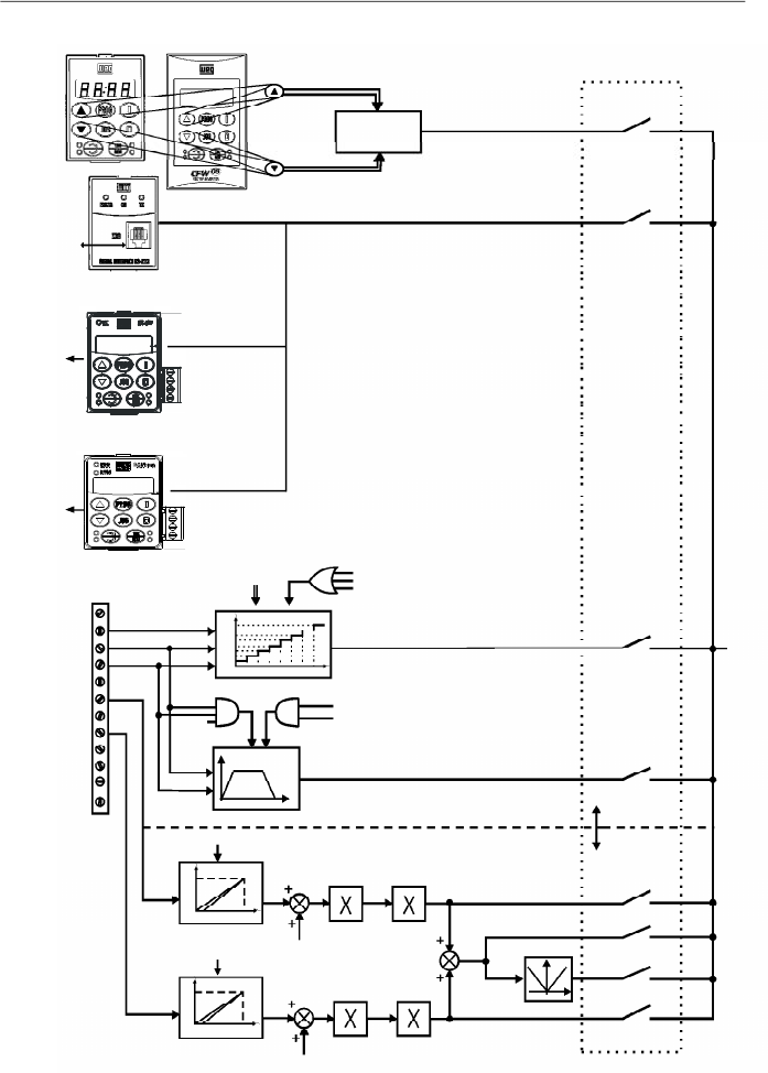
86
CHAPTER 6 - DETAILED PARAMETER DESCRIPTION
Figure 6.1
- Block diagram of the frequency reference
RS-232
PC and CLP
KEYPAD
REFERENCE
(P121)
HMI-CFW08-RPor
HMI-CFW08-RS
KCS-CFW08
P124 to P131
P264 = 7
P265 = 7
P266 = 7
MULTISPEED
Accel.
Enabling Function
P265 = 5
P266 = 5
Decel.
Inverter
Disabled
ELECTRONICPOTENTIOMETER(EP)
AI2
AI1
DI4
DI3
DI2
1
2
3
4
5
6
7
8
9
10
11
12
XC1
AI1
P235
AI2
P239
P238
P134
P234
P134
P236
P240
2 or 3 - AI2
7 - Add AI>0
8 - Add AI
1 - AI1
4 - EP
6 - Multispeed
5 - Serial or
CANopen or
DeviceNet
0 - Keypad
Frequency Reference
Selection
P221 or P222
F*
Digital
References
Analog
References
P131
P130
P129
P128
P127
P126
P125
P124
000 001 010 011 100 101110 111
100%
P239=0
P239=1
0
2V/4mA
10V/20mA
100%
P235=0
P235=1
0
2V/4mA
10V/20mA
0 V
Reset
HMI-CFW08-P
RS-485
KRS-485
KFB-CO or KFB-DN
CANopen
or
DeviceNet
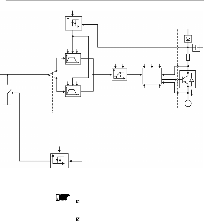
87
CHAPTER 6 - DETAILED PARAMETER DESCRIPTION
Fe
Command via
Digital Input
(DI)
Acceleration
and
Deceleration
Ramp 2
Acceleration and
Deceleration Ramp
P102
P103
P100
P101
DC Link
Regulation
P151
P151
U
d
P133
P134
Frequency
Reference
Limits
P202
P295
Inverter
Control
(V/F or
Vector)
P136,
P137,P138,
P142, P145
Motor
Parameters
(P399 to P409)
P178
V
s
PWM
P169
I
s
P169
I
s
Output Current
Limiting
I
V
s
U
d
Power
Supply
IM
3Ø
I
s
NOTE!
In V/F control mode (P202 = 0 or 1), Fe = F* (refer to figure
6.1) if P138 = 0 (slip compensation disabled). If P138
0,
refer to figure 6.9 for the relation between Fe and F*.
In vector control mode (P202 = 2) always Fe = F* (refer to
figure 6.1).
Figure 6.2
- Block diagram of the inverter control
88
CHAPTER 6 - DETAILED PARAMETER DESCRIPTION
6.2.5
Commands
6.2.6
Local/Remote
Operation Modes
The inverter has the following commands:PWMpulseenabling/
disabling, definition of the direction of rotation and JOG.
As the frequency reference, the inverter commands can de
defined in several ways.
The command sources are the following:
Via keypad - keys , , and .
Via control terminals (XC1) - digital inputs.
Via serial interface.
The inverter enabling and disabling commands can be defined
as follows:
Via keypad and of the HMI.
Via serial.
Start/stop (terminals XC1 - DI(s) - refer to the parameter
P263 to P266).
General enable (terminals XC1 - DI(s) - refer to the
parameter P263 to P266).
Forward run (terminals XC1 - DI(s) - refer to the parameter
P263 and P264), it also defines the diretion of rotation.
ON/OFF (3-wire control) (terminals XC1 - DIs - refer to the
parameters P263 and P264).
The definition of the direction of rotation can be defined by
using:
The key of the keypad.
Serial.
Digital input
(DI) program
med for FWD/REV
(
refer to the
parameter
P264 to P266)
.
Digital inputs programmed as FWD / REV, thatdefines both
Inverter enabling or disabling and direction of rotation (refer
to the parameters
P263 and P264).
Analog input - when the reference is via analog input and a
negative offset is programmed (P236 or P240<0), the
reference may assume negative values, thus reversing the
direction of the motor rotation.
User can define two different conditions relating to the
frequency reference sourceand the inverter commands: these
are the local and the remote operation modes.
Figure 6.3 shows the local and remote operation modes in a
block diagram.
With the factory setting in local mode the inverter can be
controlled by using the keypad, while in remote mode all
controls are via terminals (XC1) - reference definition and
inverter commands.
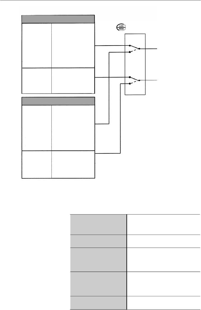
89
CHAPTER 6 - DETAILED PARAMETER DESCRIPTION
Figure 6.3
- Block diagram of the local and remote operation mode
LOCAL
Frequency
Reference
P221
Controls
P229
(stop/run,
FWD/REV
and JOG)
0
Keypad
(HMI-CFW08-P,
HMI
-CFW08-RP and
HMI-CFW08-RS)
1
AI1
2
or 3 AI2
4
EP
5
Serial
6
Multispeed
7
Add AI
8
Add AI > 0
0
Keypad (HMI-
CFW08-P and HMI-
CFW08-RP)
1
Terminals
XC1 (DIs)
2
Serial or HMI-
CFW08-RS keypad
REMOTE
Frequency
Reference
P222
Controls
P230
(stop/run,
FWD/REV
and JOG)
F* REFERENCE
COMMANDS
Local/Remote Selection (P220)
+
Local/Remote Command
( , DI, Serial, etc)
6.3
PARAMETER
LISTING
In order to simplify the explanation, the parameters have been
grouped bycharacteristics and functions:
Variables that can be viewed on the
display, but can not be changed by the
user
Programmable values used by the
CFW-08 functions
They define the inverter characteristics,
the functions to be executed, as well as
the input/output functions of the control
board
Data about the applied motor: data
indicated on the motor nameplate and
those obtained during the running of the
self-tuning routine
Here are included parameters related to
special functions
0
Keypad
(HMI
-CFW08-P,
HMI- CFW08- RP and
HMI-
CFW08-RS)
1
AI1
2
or 3 AI2
4
EP
5
Serial
6
Multispeed
7
Add AI
8
AddAI>0
0
Keypad
(HMI-CFW-08-P and
HMI - CFW-08- RP)
1
Terminals
XC1 (DIs)
2
Serial or HMI-
CFW08-RS keypad
Read-only Parameters
Regulation Parameters
Configuration Parameters
Motor Parameters
Special Function Parameters

90
CHAPTER 6 - DETAILED PARAMETER DESCRIPTION
Range
[Factory Setting]
Parameter
Unit
Description / Notes
P000
0 to 999
Parameter
[ 0 ]
Access
1
6.3.1
Access and Read-only Parameters - P000 to P099
P002
0 to 6553
Frequency
[ - ]
Proportional
0.01 (
99.99);
Value
0.1 (
100.0);
1 (
1000)
P003
0 to 1.5 x I
nom
Motor Output
[ - ]
Current
0.01 A (
9.99 A);
0.1 A (
10.0 A)
P004
0 to 862
DC Link Voltage
[ - ]
1
V
Releases the access to change the parameter values.
The password is 5.
The use of the password is always active.
Indicates the value of P208 x P005.
When the vector control mode is used (P202 = 2), P002
indicates the actual motor speed in rpm.
In case of different scales and units, use P208.
Indicates the inverter output current inAmps (A).
Indicates the actual DC link voltage, in volts (V).
P005
0
.00
to
300
.0
Motor
Output
[ - ]
Frequency
0.01 Hz
(
99.99 Hz);
0.1 Hz (
100.0 Hz)
Indicates the inverteroutput frequency in Hertz (Hz).
P007
0 to 600
Motor Output
[ - ]
Voltage
1 V
Indicates the inverter output rms voltage, in volts (V).
Following notes may appear in some parameters during the
detailed description:
(1)
This parameter is onlydisplayed in vector mode (P202 = 2).
(2)
This parameter is only displayed in
scalar mode P202 = 0
or 1.
(3)
This parameter can be changed only when the inverter is
disabled (stopped motor).
(4)
This parameter is onlyavailable with HMI-CFW08-RS.
(5)
The analog input value is represented by zero when it is
not connected to an external signal. In order to use ananalog
input as a digital input with NPN logic (P235 or P239 = 3),
it is necessary to connect a 10 k
resistor from terminal 7
to 6 (AI1) or 8 (AI2) of the control terminal strip.
(6)
This parameter is only available in the CFW-08 Plus
version.
(7)
The parametervalue changesautomaticallywhen P203 = 1.

91
CHAPTER 6 - DETAILED PARAMETER DESCRIPTION
P008
25 to 110
Heatsink
[ - ]
Temperature
1
o
C
Indicates the current power at the heatsink in Celsius
degrees (°C).
Theinverter overtemperature protection (E04) actswhen
heatsink temperature reaches:
P009
(1)
0.0 to 150.0
Motor Torque
[ - ]
0.1 %
Indicates the torque developed by motor in percent (%)
relating to the set rated motor torque.
The rated motor torque is defined by the parameters
P402 (rated motor speed) and P404 (rated motor power).
I.e.:
Range
[Factory Setting]
Parameter
Unit
Description / Notes
Table 6.1
- Temperature to act the overtemperature protection
P023
x.yz
Software Version
[ - ]
-
P040
0 to 6553
PID Process
[ - ]
Variable
1
(Value % x P528)
Indicates the software version installed in the DSP
memory located on the control board.
Parameter
P040, P203, P520
to
P528
are only available
from the software version V3.50 on.
Indica
tes the value of the process variable
u
sed as PID
feedback, in percent (%).
The PID function is only available from the software
version V3.50 on.
The indication unit can be changed through P528.
Refer to detailed description of the PID regulator in item
6.3.5 - Special Function Parameters.
where T
nom
is given in kgf.m, P
nom
is the rated motor power
in watts - HP - (P404), and n
nom
is the rated motor speed
in rpm - P402.
P014
00 to 41
Last Fault
[ - ]
-
Indicates the code of the last occured fault.
Item
7.1
shows a list of possible faults
,
their code numbers
and possible causes.
T
nom
= 716 .
P
nom
n
nom
Inverter
1.6-2.6-4.0-7.0A/200-240 V
1.0-1.6-2.6-4.0A/380-480 V
7.3-10-16A/200-240 V
2.7-4.3-6.5-10A/380-480 V
13-16A/380-480 V
22-28-33A/200-240 V
24-30A/380-480 V
P008 in ºC (ºF) @ E04
103 (217.4)
90 (194)
90 (194)
103 (217.4)
108 (226.4)
104 (219.2)
104 (219.2)
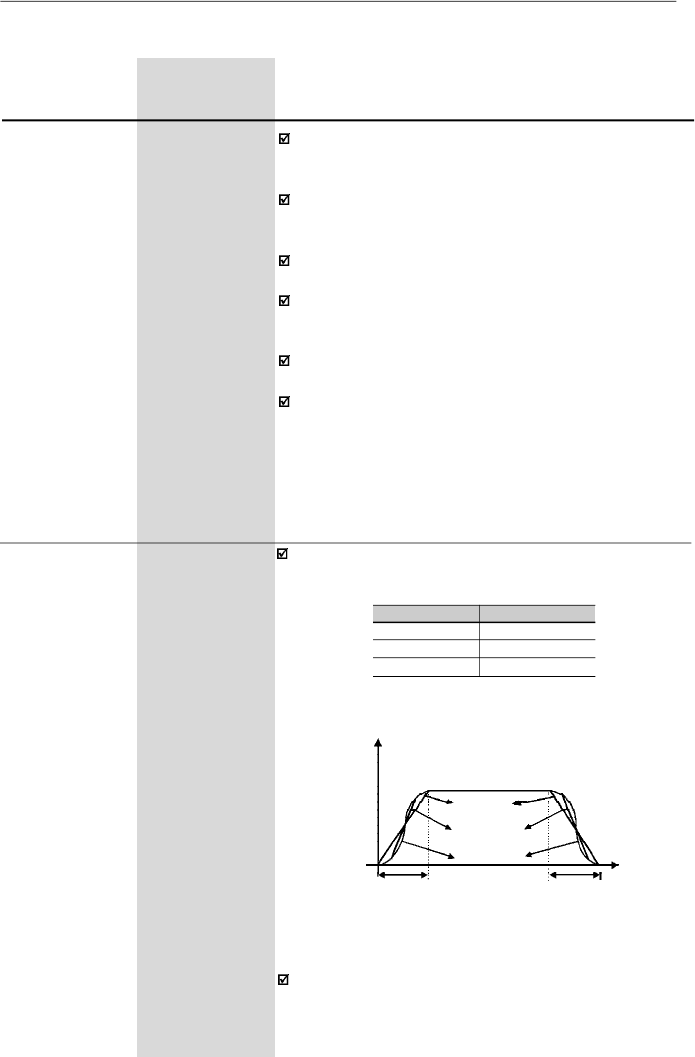
92
CHAPTER 6 - DETAILED PARAMETER DESCRIPTION
Range
[Factory Setting]
Parameter
Unit
Description / Notes
0.1 to 999
[ 5.0 s ]
0.1s (
99.9 s);
1s (
100 s)
0.1 to 999
[ 10.0 s ]
0.1s (
99.9 s);
1s (
100 s)
0.1 to 999
[ 5.0 s ]
0.1s (
99.9 s);
1s (
100 s)
0.1 to 999
[ 10.0 s ]
0.1s (
99.9 s);
1s (
100 s)
This set of parameters defines the time to accelerate
linearly from zero up to the rated frequency and to
decelerate linearly from the rated frequency down to zero.
The rated frequency is defined by parameter:
- P145 in V/F control (P202 = 0 or 1).
- P403 in vector control (P202 = 2).
When factorysetting is used, inverter always follows the
time defined in P100 and P101.
If r
amp
2 is used
,
the acceleration and deceleration times
follow the values programmed at
P102
and
P103,
use a
digital input
.
Refer to the parameters
P263 to P265.
Depending on the load inertia, too short acceleration ti-
mes can disable the inverter due to overcurrent (E00).
Depending on the load inertia, too short deceleration ti-
mes can disable the inverter due to overvoltage (E01).
For more details, refer to the parameter P151.
6.3.2
Regulation Parameters - P100 to P199
P100
Acceleration
Time
P101
Deceleration
Time
P102
Ramp 2
Acceleration
Time
P103
Ramp 2
Deceleration
Time
P104
0 to 2
S Ramp
[ 0 ]
-
The S ramp reduces mechanical stress during the
acceleration and deceleration of the load.
Output Frequency
(Motor Speed)
P104
0
1
2
S Ramp
Inactive
50 %
100 %
Linear
t (s)
Acceleration Time
(P100/P102)
Deceleration Time
(P101/P103)
50 % S ramp
100 %
S
ramp
Figure 6.4
- S or linear ramp
It is recommended to use the S ramp with digital
frequency/speed references.
Table 6.2
-
S ramp configuration
93
CHAPTER 6 - DETAILED PARAMETER DESCRIPTION
Range
[Factory Setting]
Parameter
Unit
Description / Notes
P120
0 to 2
Digital Reference
[ 1 ]
Backup
-
It defines if the inverter should save or not the last used
digital reference. This backup function is onlyapplicable
to the keypad reference (P121).
If the digital reference backup is inactive (P120 = 0),the
frequency reference will be equal to the minimum
frequency everytime the inverter is enabled, according
to P133.
If P120 = 1, the inverter stores the digital reference value
automatically (for either keypad, EP or serial reference
source) every time the inverter is disabled, either by a
disable condition (Start/Stop or General Enable), error
or undervoltage.
If P120 = 2, then every time the inverter is enabled its
initial reference is given by the value adjusted in the
parameter P120, which remains stored, regardless of
the reference source.
Application example: when the reference is via EP and
the inverter is disabled via the EP Deceleration digital
input, its reference is reduced to 0 (zero). When P120 =
2, then at a newenabling the inverter accelerates to the
value programmed in P121, not to the minimum
reference.
P121
P133 to P134
Keypad
[ 3.00 Hz ]
Reference
0.01 Hz
(
99.99 Hz);
0.1 Hz
(
100.0 Hz)
Allows the setting of the output frequency to the motor
through and keys.
This setting may also be performed while visualizing
parameters P002 and P005.
The ke
ys
and
are enabled if P221 = 0 (in local
mode) or
P222
=
0 (
in remote mode
).
The value of
P121
is maintained at the last set value, even when inverter is
disabled or turned OFF, provided P120 = 1 or 2 (backup
active).
P120
0
1
2
Reference Backup
Inactive
Active
Active, but always given by P121,
independently of the sorce reference
Table 6.3 -
Digital reference backup configuration
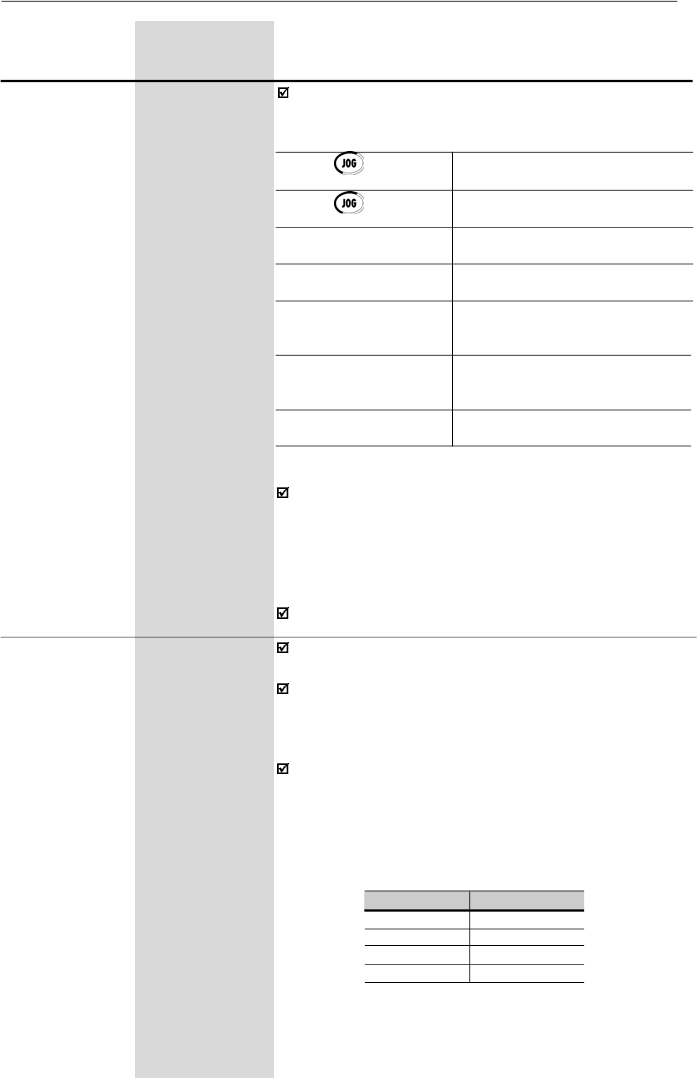
94
CHAPTER 6 - DETAILED PARAMETER DESCRIPTION
Range
[Factory Setting]
Parameter
Unit
Description / Notes
To operate JOG function works, the inverter must be
disabled by ramp (stopped motor). Thus if the control
source is via terminal, there must be at least one digital
inputprogrammed as start/stop enabling (otherwise E24
will be displayed),which mustbe OFF to enable the JOG
function via digital input.
The direction of rotation is defined by parameter P231.
Multispeed is used when the selection of a number up to
8 pre-programmed speeds is desired.
It allows the control of the output speed by relating the
values programmed by the parameters P124 to P131,
according to the logical combination of the digital inputs
programmed for multispeed.
Activation of the multispeed function:
-
Ensure that the reference source is given by the
multispeed function, i.e., set P221 = 6 in local mode or
P222 = 6 in remote mode;
-
Program one or more digital inputs to multispeed,
according to table below:
P124
P133 to P134
Multispeed
[ 3.00 Hz ]
Reference 1
0.01 Hz
(
99.99 Hz);
0.1 Hz
(
100.0 Hz)
P125
P133 to P134
Multispeed
[ 10.00 Hz ]
Reference 2
0.01 Hz
(
99.99 Hz);
0.1 Hz
(
100.0 Hz)
P126
P133 to P134
Multispeed
[ 20.00 Hz ]
Reference 3
0.01 Hz
(
99.99 Hz);
0.1 Hz
(
100.0 Hz)
Note:
Digital inputs DI2 and Dl5 shall not be set for multispeed
function simultaneously. In case it happens, the frequency inverter
will indicate an E24 error (programming error).
Table 6.5
- Parameters setting for defining the multispeed
function through digital inputs
DI
Programming
DI2
P264 = 7
DI3
P265 = 7
DI4
P266 = 7
DI5
P267 = 7
Defines the frequency reference (speed) for the JOG
function. The JOG function can be activated in several
ways:
P122
0.00 to P134
JOG Speed
[ 5.00 Hz ]
Reference
0.01 Hz
(
99.99 Hz);
0.1 Hz
(
100.0 Hz)
Table 6.4 -
JOG reference configuration
The
key of the
HMI-CFW08-P
The
key of the
HMI-CFW08-RS
DI3
DI4
DI5
DI6
Serial
P229 = 0 (local mode) or
P230 = 0 (remote mode)
P229 = 2 (local mode) or
P230 = 2 (remote mode)
P265 = 3 and P229 = 1 (local) or
P230 = 1 (remote)
P266 = 3 and P229 = 1 (local) or
P230 = 1 (remote)
Adjustment switch S1.3 set to Off;
P235 = 2 or P235 = 3 or P235 = 4;
P229 = 1 or P230 = 1 and P267 = 3
Adjustment switch S1.4 set to Off;
P239 = 2 or P239 = 3 or P239 = 4;
P229 = 1 or P230 = 1 and P268 = 3
P229 = 2 (local mode) or
P230 = 2 (remote mode)
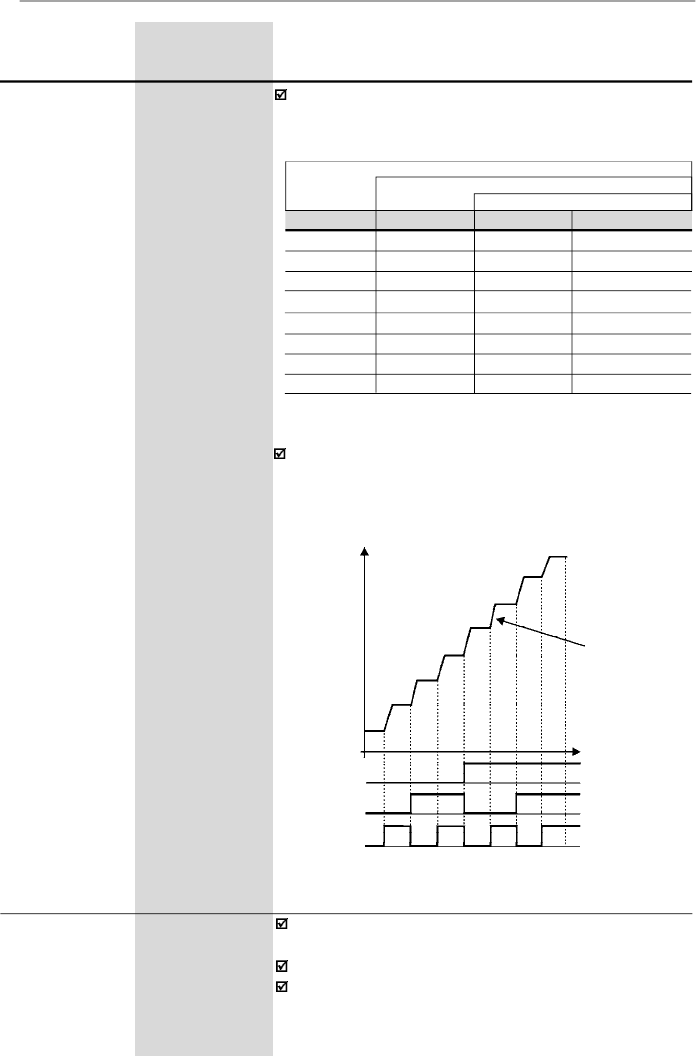
95
CHAPTER 6 - DETAILED PARAMETER DESCRIPTION
Range
[Factory Setting]
Parameter
Unit
Description / Notes
P127
P133 to P134
Multispeed
[ 30.00 Hz ]
Reference 4
0.01 Hz
(
99.99 Hz);
0.1 Hz
(
100.0 Hz)
P128
P133 to P134
Multispeed
[ 40.00 Hz ]
Reference 5
0.01 Hz
(
99.99 Hz);
0.1 Hz
(
100.0 Hz)
P129
P133 to P134
Multispeed
[ 50.00 Hz ]
Reference
6
0.01 Hz
(
99.99 Hz);
0.1 Hz
(
100.0 Hz)
P130
P133 to P134
Multispeed
[ 60.00 Hz ]
Reference 7
0.01 Hz
(
99.99 Hz);
0.1 Hz
(
100.0 Hz)
P131
P133 to P134
Multispeed
[ 66.00 Hz ]
Reference
8
0.01 Hz
(
99.99 Hz);
0.1 Hz
(
100.0 Hz)
The frequency reference is defined by the status of the
digital inputs programmed to multispeed as shown in
table below:
DI2 or DI5
DI3
DI4
Freq. Reference
Open
Open
Open
P124
Open
Open
0 V
P125
Open
0 V
Open
P126
Open
0 V
0 V
P127
0 V
Open
Open
P128
0 V
Open
0 V
P129
0 V
0 V
Open
P130
0 V
0 V
0 V
P131
8 speeds
4 speeds
2 speeds
Table 6.6
- Frequency reference
The multispeed function has some advantages for the
stability of the fixed preprogrammed references and the
immunityagainst electrical noises (digital references and
insulated digital inputs).
P128
P129
P130
P131
Output
Frequency
Acceleration
Ramp
P126
P127
Figure 6.5
- Time diagram of the multispeed function
Time
0 V
DI2 or DI5
DI3
DI4
Open
0 V
Open
0 V
Open
P124
P125
P133
0.00 to P134
Minimum
[
3.00 Hz
]
Frequency
(F
min
)
0.01 Hz
(
99.99 Hz);
0.1 Hz
(
100.0 Hz)
Define
s the maximum and minimum output frequency
(motor)
when inverter is enabled.
It is valid for any type of speed reference excepting JOG.
The parameter P133 defines a dead zone when analog
inputs are used - refer to the parameter P233 to P240.
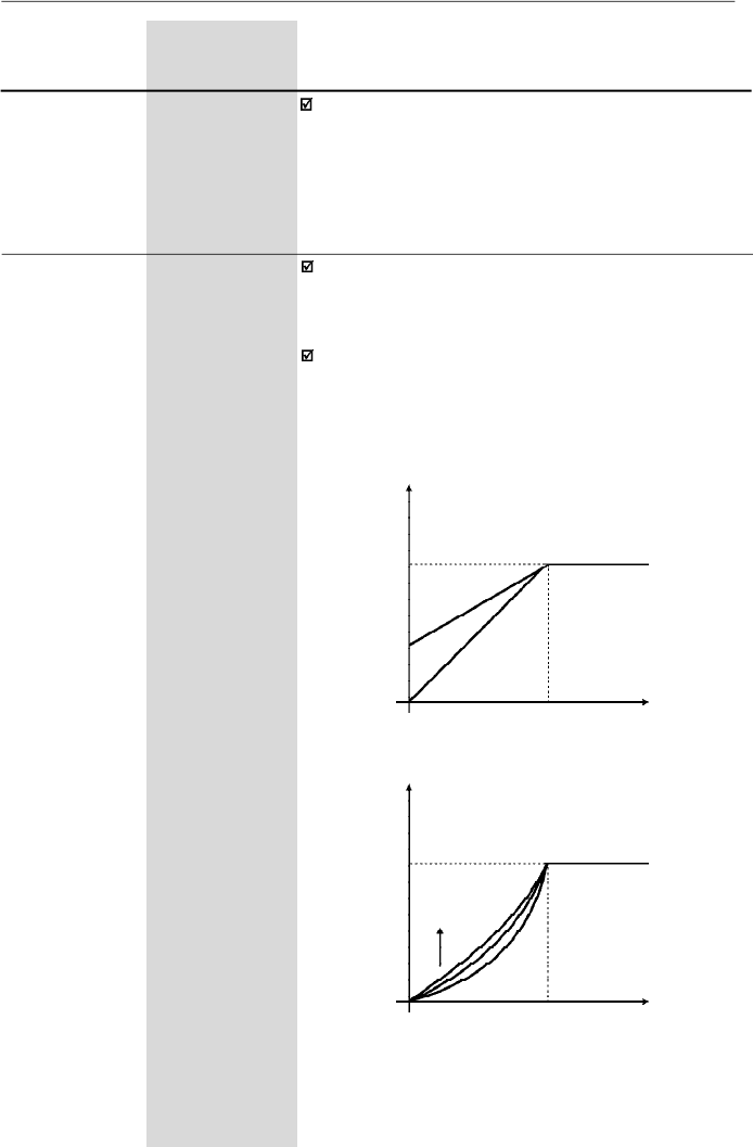
96
CHAPTER 6 - DETAILED PARAMETER DESCRIPTION
Range
[Factory Setting]
Parameter
Unit
Description/Notes
P134
P133 to 300.0
Maximum
[
66.00 Hz ]
Frequency
(F
max
)
0.01 Hz
(
99.99 Hz);
0.1 Hz
(
100.0 Hz)
P134 and the gain and offset of the analog input(s) (P234,
P236, P238 and P240) defines the scale and the range
of the speed variation via analog input(s). For more
details refer to the parameter P234 to P240.
P136
(2)
0.0 to 30.0
Manual Torque
[
5.0 %
for
Boost
(IxR
1.6-2.6-4.0-7.0A/
Compensation)
200-240 V and
1.0-1.6-2.6-4.0A/
380-480 V;
2.0 %
for
7.3-10-16 A/
200-240 V and
2.7-4.3-6.5-10A/
380-480 V;
1.0 %
for
22-28-33 A/
200-240 V and
13-16-24-30 A/
380-480 V]
0.1 %
Compensates the voltage drop due to the motor stator
resistance. It acts at low speeds by increasing the inver-
ter output voltage, in order to maintain a constant torque
during the V/F operation.
The best setting is to program the lowest value for P136
that still permits the motor start satisfactorily. If the value
is higher than required, an inverter overcurrent (E00 or
E05) may occur due to high motor currents at lowspeeds.
Figure 6.6 a) and b)
- V/F curve and details of the manual torque
boost (IxR compensation)
Output Voltage
(% of the line voltage)
P142
P136 x P142
0
P145
Output
Frequency
b) P202 = 1
a) P202 = 0
Output Voltage
(% of the line voltage)
P142
P136
0
P145
Output
Frequency
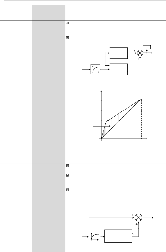
97
CHAPTER 6 - DETAILED PARAMETER DESCRIPTION
Range
[Factory Setting]
Parameter
Unit
Description / Notes
Compensation Zone
Maximum
(P142)
Output Voltage
Output
Frequency
Field
Weakening (P145)
4 Hz
0
Figure 6.8
- V/F curve with automatic torque boost
(automatic IxR compensation)
P138
(2)
0.0 to 10.0
Slip
[0.0]
Compensation
0.1 %
The parameter P138 is used in the motor slip
compensation function.
This function compensates the drop of the motor speed
due to load, which is a inherent characteristic relating to
the operation principle of the induction motor.
This speed drop is compensatedby increasing the output
frequency (and voltage) (applied to the motor) as a
function of the increase of the active motor current, as
shown in the block diagram and in the V/F curve below.
P137
(2)
0.00 to 1.00
Automatic Torque
[
0.00
]
Boost
-
(Automatic IxR
Compensation)
Theautomatic torque boost compensates forthe voltage
drop in the stator resistance in function of the active motor
current.
The criteria for setting P137 are the same of the
parameter P136.
Figure 6.7
- Block diagram of the automatic torque boost function
Slip
Compensation
OutputActive
Current (I
a
)
Frequency
Reference (F*)
Ramp Input
Frequency (Fe)
F
Filter
P138
Figure 6.9
- Block diagram of the slip compensation function
Speed
Reference (F*)
Output
Active
Current (I
a
)
Filter
Automatic
Torque Boost
P137
Manual
Torque Boost
P136
P007
Motor
Voltage
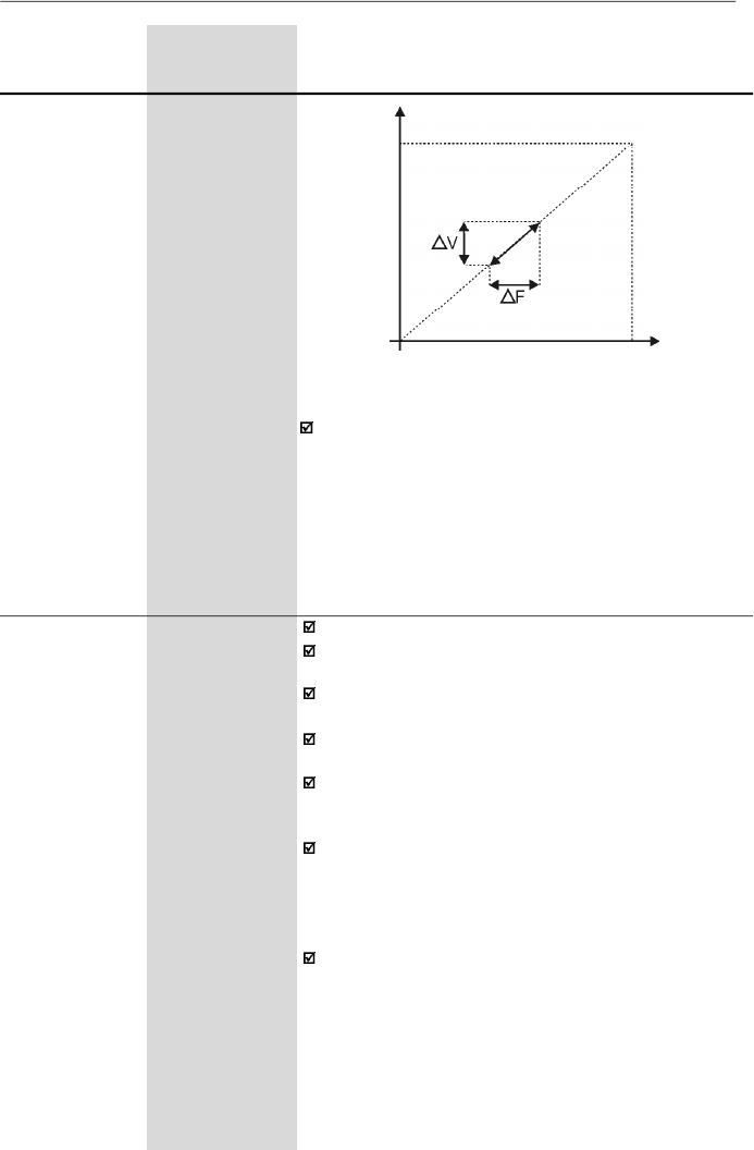
98
CHAPTER 6 - DETAILED PARAMETER DESCRIPTION
Range
[Factory Setting]
Parameter
Unit
Description / Notes
To set the parameter P138 use the following procedure:
-
Run the motor without load up to approximately half of
the application top speed.
-
Measure the actual motor or equipment speed.
-
Apply rated load to equipment.
-
I
ncr
ease parameter
P138
until the speed reaches its
no-load speed.
P142
(2) (3)
0 to 100
Maximum Output
[ 100 % ]
Voltage
1 %
P145
(2) (3)
P133 to P134
Field Weakening
[ 50.00 Hz or
Frequency
60.00 Hz
(F
nom
)
depending on
the market ]
0.01Hz
(
99.99Hz);
0.1 Hz
(
100.0 Hz)
Define the V/F curve used in V/F control (P202 = 0 or 1).
These parameters allow changing the standard V/F cur-
ve defined at P202 - Control Mode.
P142sets the maximum outputvoltage. This value is set
as a percent of the inverter supply voltage.
Parameter P145 defines the rated frequency of the mo-
tor used.
The V/F curve relates the inverter output voltage and
frequency (applied to the motor) and consequently the
magnetizing flux of the motor.
The programmable V/F curve can be used in special
applications where the motors used require a rated
voltage and/or frequency
different than the standard
ones. Examples: motor for 220 V/400 Hz and a motor for
200 V/60 Hz.
Parameter P142 is also useful in appplications that
require motor rated voltage different from the inverter
supply voltage. Example: 440 V line and 380 V motor.
Figure 6.10 -
V/F curve with slip compensation
Output Voltage
(function of
the motor
load)
Output
Frequency
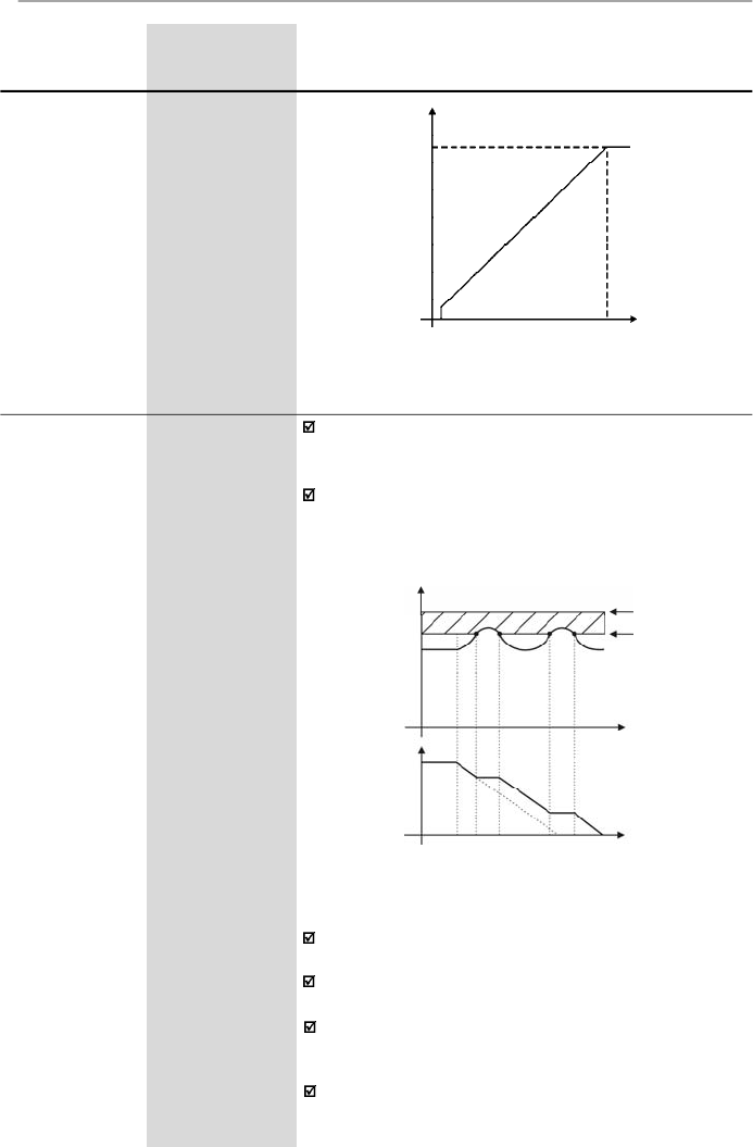
99
CHAPTER 6 - DETAILED PARAMETER DESCRIPTION
Range
[Factory Setting]
Parameter
Unit
Description / Notes
P151
325 to 410
DC Link Voltage
(line 200-240 V)
Regulation Level
[ 380 V ]
1 V
564 to 820
(line 380-480 V)
[ 780 V ]
1 V
The DC link voltage regulation
(
ramp
holding)
avoids
overvoltage trips
(E01)
during deceleration of high inertia
loads and/or short deceleration times.
It acts in order to increase the deceleration time
(according to load - inertia), thus avoiding the E01
activation.
Figure 6.11
- Adjustable V/F curve
Output Voltage
Output
Frequency
P145
0.1 Hz
0
P142
E01 - Overvoltage
CI Limitation
Cl Voltage
Ud (P004)
Time
Output
Frequency
(Motor Speed)
Rated Ud
P151
Time
Figure 6.12
- Deceleration curve with DC Link voltage limitation
(regulation)
DC Link
Voltage
By this function an optimized deceleration time
(minimum) is achieved for the driven load.
This function is useful in applications with medium inertia
that require short deceleration times.
In case of overvoltage trip (E01) during the decelearation,
you must reduce graduallythe value of P151 or increase
the time of the deceleration ramp (P101 and/or P103).
The motor will not stop if the line is permanently with
overvoltage (U
d
> P151). In this case, reduce the line
voltage or increase the value of P151.
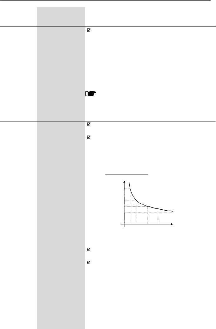
100
CHAPTER 6 - DETAILED PARAMETER DESCRIPTION
Range
[Factory Setting]
Parameter
Unit
Description / Notes
If even with these settings the motor doesnotdecelerate
within the required time, you will have the following
alternatives
-
Use the dynamic braking (for more details, refer to the
item 8.23).
-
If inverter is being operated in V/F control, increase
P136.
-
If inverter is being operated in vector control, increase
P178.
NOTE!
When dynamic braking is used, set P151 to the
maximum value.
P156
0.2xI
nom
to 1.3xI
nom
Motor Overload
[ 1.2xP401 ]
Current
0.01 A (
9.99 A);
0.1 A (
10.0 A)
This function is used to protect the motor againstoverload
(Ixt function - E05).
Themotoroverloadcurrentisthecurrentlevelabovewhich
the in verter will consider the motor operating under
overload. The higher the difference between the motor
current and the overload current, the sooner theIxt function
- E05 will act.
Figure 6.13
- Ixt function – overload detection
3.0
2.0
1.5
1.0
15 30 60 90
Time (s)
Motor current (P003)
Overload current
Parameter P156 must be set from 10 % to 20 % higher
than the rated motor current (P401).
Always P401 is changed, P156 is adjusted automatically.
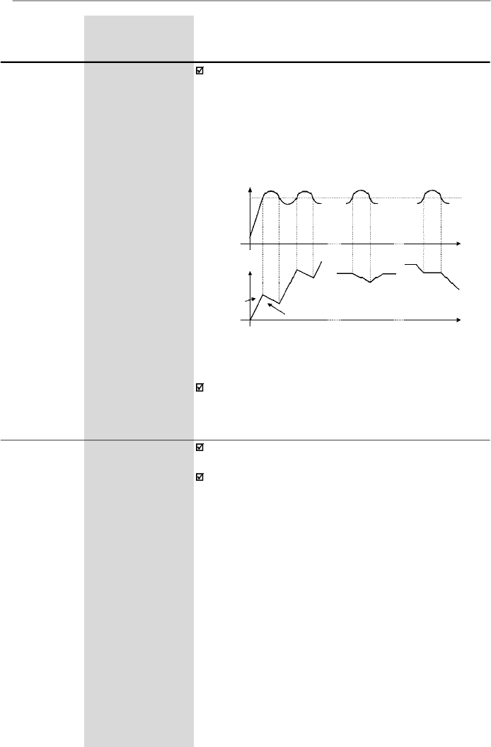
101
CHAPTER 6 - DETAILED PARAMETER DESCRIPTION
Range
[Factory Setting]
Parameter
Unit
Description / Notes
Prevents motor stalling during an overload
.
If motor load
increases its current will increase too
.
If the motor current
attempts to exceed
the value set at
P169,
the motor
speed will be decreased by following the deceleration
ramp until the current becomes lower than P169.
As soon as the overload condition disappears, the mo-
tor speed is resumed.
P169
0.2xI
nom
to 2.0xI
nom
Maximum
[ 1.5 x P295 ]
Output Current
0.01 A (
9.99 A);
0.1 A (
10.0 A)
Figure 6.14
- Curves showing the actuation of the current limitation
Time
during
cont. duty
Time
Motor current
Deceleration ramp (P101/P103)
deceleration
ramp
acceleration
ramp
during
deceleration
during
acceleration
acceleration
ramp
(P100/P102)
Speed
P169
The current limitation function is disabled when
P169 > 1.5 x P295.
P178
(1)
50.0 to 150
Rated Flux
[ 100 % ]
0.1 % (
99.9 %);
1 % (
100 %)
Defines the fluxin the motor airgap,when invector control.
It is expressed as a percentage (%) of the nominal flux.
Generally it is not necessary to change P178 of the
default value (100 %). But in some specific cases,
different values at P178 may be set.These conditions may
be:
-
To increase the inverter torque capacity
(P178 > 100 %).
Examples:
1)
to increase the motor starting torque and thus ensure
faster motor starts;
2)
toincrease the inverter braking torque and thusallow
faster stops, without using dynamic braking.
-
Toreduce theinverterenergyconsumption
(P178<100%).
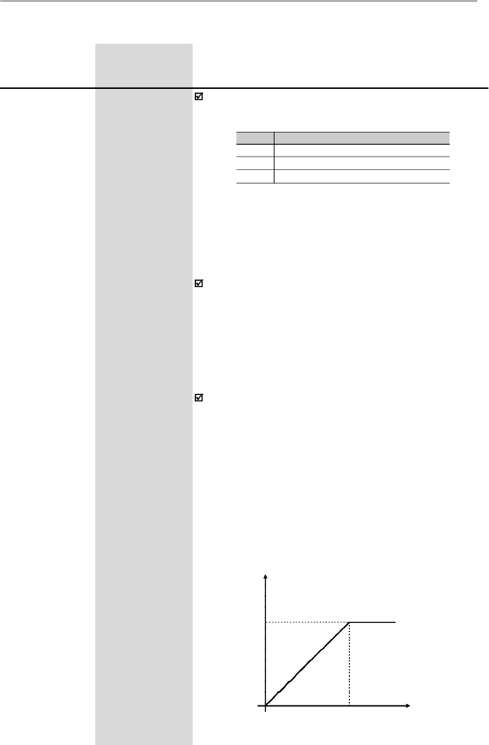
102
CHAPTER 6 - DETAILED PARAMETER DESCRIPTION
Range
[Factory Setting]
Parameter
Unit
Description / Notes
Defines the inverter control mode. Item 5.3 gives some
guidelines relating to the selection of control mode.
P202
(3)
0 to 2
Control Mode
[ 0 ]
-
As shown in table above, there are 2 V/F control modes
and one vector control mode.
Scalar control modes:
LinearV/F control: this control mode ensures a flux in the
motor air gap approximately constant from around
3
Hz
up to the field weakening
(defin
ed by the parameters
P142 and P145).
Thus in this speed range, an approximately constant
torque capacity is obtained.
This control mode is
recommended for belt conveyors, extruding machines,
etc.
Quadratic V/F control:in this control mode the flux in the
motor air gap is proportional to the output frequency up
to the field weakening point (defined at P142 and P145).
Thus the torque capacity is a quadratic function of the
speed. The main advantage of this type of control is the
energysaving capabilitywith variable torque loads, due
to the reduction of the motor losses (mainlydue to motor
iron losses and magnetic losses).
Main application fields for this type of control are:
centrifugal pumps, fans, multimotor drivings.
6.3.3
Configuration Parameters - P200 to P398
Output Voltage
P136 = 0
P142
0
P145
Output
Frequency
P202
0
1
2
Control Mode
Linear V/F Control (scalar)
Quadratic V/F Control (scalar)
Sensorless Vector Control
a) Linear V/F
Table 6.7
- Adjustment for each control mode
Figure 6.15 a)
- V/F control modes (scalar)
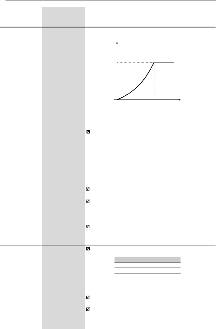
103
CHAPTER 6 - DETAILED PARAMETER DESCRIPTION
Range
[Factory Setting]
Parameter
Unit
Description / Notes
Selects or not the special function of the PID Regulator.
P203
(3)
0 or 1
Special Function
[ 0 ]
Selection
-
P203
0
1
Special Function
None
PID Regulator
Refer to detailed description of PID Regulator
parameters (P520 to P528).
When
P203
is changed to
1, P265
is changed
automaticallyto 15 (DI3 = manual/automatic).
The vector control allows a better performance regarding
to torque and speed control. The CFW-08 vector control
operateswithout motorspeed sensor (sensorless). It must
be applied when following performances are required:
- Better dynamics (faster accelerations and stoppings).
-
When more accurate speed control is required.
- When high torques at lowspeeds are required (
5 Hz).
Ex
a
mpl
e
s:
in positioning, such as load moving, packing
machines, dosing machines, etc.
The vector control can not be used in multimotor
applications.
The performance of the vector control with a switching
frequency of 10 kHz is not so good as when a switching
frequencyof 5 kHz or2.5 kHz is used. It is not possible to
use a vector control with a switching frequency of 15kHz.
For more details about the vector control, refer to item
6.2.3.
Figure 6.15 b)
-V/F control modes (scalar)
Output Voltage
P136 = 0
P142
0
P145
Output
Frequency
b) Quadratic V/F
Vector control modes:
Table 6.8
- Configuration of P203 for using or not the special
function PID Regulator
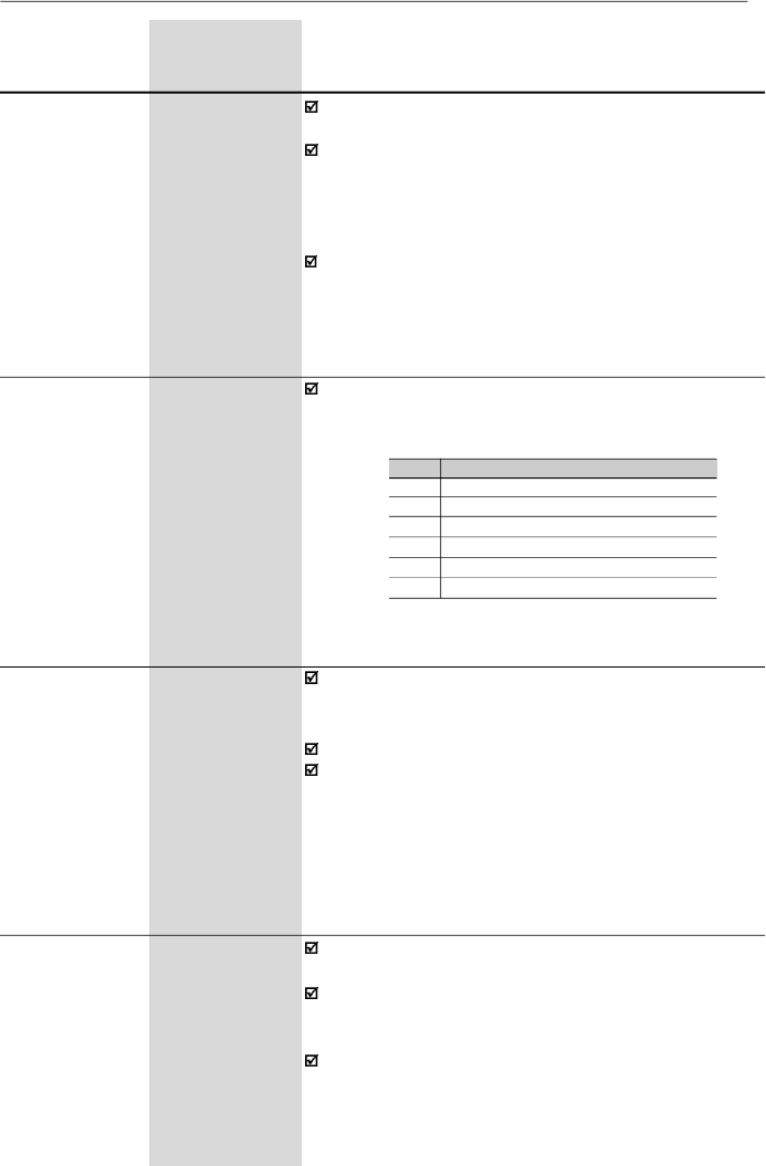
104
CHAPTER 6 - DETAILED PARAMETER DESCRIPTION
P205
0
1
2
3
4 and 5
6
Read Parameter
P005 [Output Frequency (Motor)]
P003 [Output Current (Motor)]
P002 (Value Proportional to Frequency)
P007 [Output Voltage (Motor)]
Not Used
P040 (PID Process Variable)
In the event of a fault trip, except for E14, E24 and E41,
the inverter can initiate an automatic reset after the time
given by P206 is elapsed.
If P206
2 auto-reset does not occur.
If after auto-reset the same fault is repeated three times
consecutively, the auto-reset function will be disabled.A
fault is considered consecutive if it happens again within
30 seconds after the auto-reset. Thus if a fault occurrs
four times consecutively, this fault remains indicated
permanently (and inverter disabled).
P206
0 to 255
Auto-Reset Time
[
0
]
1 s
Range
[Factory Setting]
Parameter
Unit
Description / Notes
Programs all parameters to the standard factory default,
when P204 = 5.
The parameters P142 (maximum output voltage), P145
(field weakening frequency), P295 (rated current), P308
(inverter address) and P399 to P407 (motor parameters)
are notchanged when the factorydefault parameters are
loaded through P204 = 5.
When P204 is set to 5 with the version “A2” of the control
board, it is necessary to set P234 and P238 to 2 as well
as P236 and P240 to -50 % so that the analog inputs
can be bipolar (-10 to +10) Vdc.
Selects which of the parameters listed below will be
shown on the display as a default after the inverter has
been powered up.
P205
0 to 6
Display
[ 2
]
Default
-
Selection
P204
(3)
0 to 5
Load Factory
[ 0 ]
Setting
-
It allows that the read-onlyparameter P002 indicates the
motor speed in value, for instance, rpm.
The indication of P002 is equal to the output frequency
value (P005) multiplied by the value of P208, i.e.,
P002 = P208 x P005.
If desired, the conversion from Hz to rpm is made as a
function of the pole number:
P208
0.00 to 99.9
Reference Scale
[ 1.00 ]
Factor
0.01 (
9.99)
0.1 (
10.0)
Table 6.9
- Configuration of P205

105
CHAPTER 6 - DETAILED PARAMETER DESCRIPTION
Range
[Factory Setting]
Parameter
Unit
Description / Notes
Always when programmed to vector mode (P202 = 2),
the parameter P208 is set according to the value of P402
(motor speed) to indicate the speed in rpm, in P002.
The purpose of the sleep function is to identify an
operation point where the inverter does not interfere with
thesystem in which it is inserted, sothatit can be switched
off. However, the inverter status in the internal variables
and via serial interface remains as enabled, even though
there are no PWM pulses atthe inverter output
.
The parameter P212 defines a frequency value at the
ramp input (FE) belowwhich the inverter is able to enter
the “Sleep Mode”.
The “Sleep Mode” disables the inverter when the
frequencyreference is lower than the P212 value. If this
conditions is reverted, i.e., if the frequency rises above
P212, the inverter is automatically enabled again.
Besides P212, the “Sleep Mode” depends also of the
parameters P213 and P535.
When the “Sleep Mode” is active the CFW08 indicates
“Srdy” on the HMI.
P212
0.00 to P134
Frequency to
[ 0.00 ]
Enable the
0.01 Hz
Sleep Mode
(
99.99 Hz)
0.1 Hz
(
100.0 Hz)
The parameter P213 sets the interval while the “Sleep
Mode” conditions defined by P212 and P535 must
remain unchanged. This avoids that disturbances and
momentary oscillations activate the “Sleep Mode”
improperly
.
P213
0.1 to 999
Time Delay to
[ 2.0 ]
Activate the
0.1 s (
99.9 s)
Sleep Mode
1 s (
100 s)
Motor Pole Number
II poles
IV poles
VI poles
P208 to P002 Indicate
the Speed in rpm
60
30
20
Table 6.10
- Configuration of P208 so P002 indicates
the motor speed in rpm

106
CHAPTER 6 - DETAILED PARAMETER DESCRIPTION
Range
[Factory Setting]
Parameter
Unit
Description / Notes
P215
(3) (4)
0 to 2
Keypad Copy
[ 0
]
Function
-
The keypad copy function is used to transfer the content
of the parameters from one inverter to another.
P215
0
1
2
Notes
-
Transfers the current parameter values
of the inverter to non volatile memory
(EEPROM) of the HMI-CFW08-RS
keypad. The current inverter parameters
are not changed
Transfers the content of the non volatile
memoryof the HMI-CFW08-RS keypad
(EEPROM) to the current inverter
parameters
Action
No Function
Procedure is as follows:
1.
Connectthe keypad (HMI-CFW08-RS)to the inverter
from which the parameters will be copied (inverterA -
source inverter).
2. Set P215 = 1 (copy) to transfer the parameter values
from the inverter A to the keypad. Press key.
During running of the Copy function, display will show
.
P2
15
resets automatically to
0 (
Off
)
after transfer has been completed.
3.
Disconnect the keypad from the inverter (A).
4.
Con
n
ect the same keypad to the inverter to which
the
parameters will be transferred (
i
nverter B - target
inverter).
5.
Set P215 = 2 (paste) to transfer the contentof the non
volatile memory of the keypad (EEPROM - has the
inverterA parameters) to inverter B. Press the key.
While the keypad is running the paste function, the
displayshows
,
anabbreviationforpaste.
When P215 returns to 0, the parameter transfer has
been concluded. Now inverters
A
and
B
will have the
same parameter values.
Copy
(inverter
keypad)
Paste
(keypad
inverter)
Table 6.11
- Programming P215 for Copy function execution
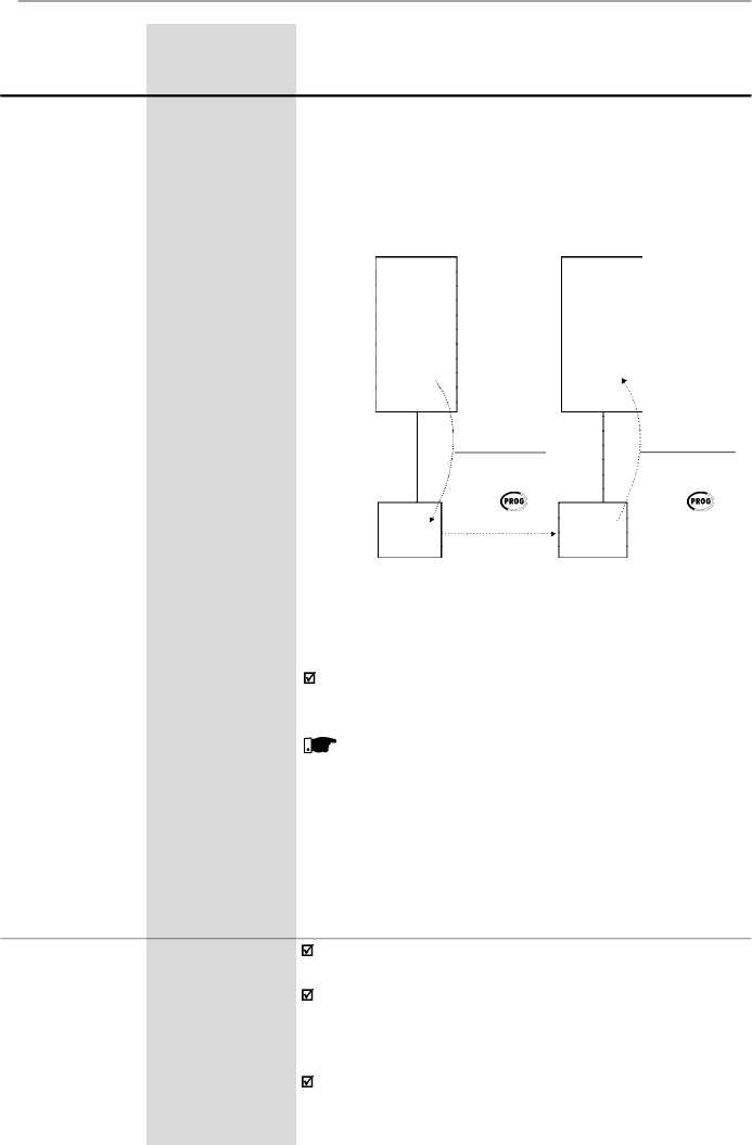
107
CHAPTER 6 - DETAILED PARAMETER DESCRIPTION
Range
[Factory Setting]
Parameter
Unit
Description / Notes
Figure 6.16
- Coping the parameters from the inverter A to the
inverter B, by using the Copy function and the HMI-CFW08-RS
keypad
Whilethe keypad (HMI) is runningthe Copy function (read
or write procedures), you can not operate it.
NOTE!
The copy function is onlyavailable when the inverters
are of the same model (voltageand current) and when
compatible software versions are installed. The
sofware version is considered compatible when the
digits
x
and
y (Vx.yz)
are equal
.
If they are different,
E10
will be displayed and the parameters will not be
loaded to the destination inverter
.
Please consider still the following:
-
If the invertersAand B are driving different motors,
check the motor parameters (P399 to P409) related
to inverter B.
-
To copy the parameter content of the inverterA to
other inverter(s), repeat steps 4 and 5 above.
Parameters
Parameters
EEPROM
INVERTER
B
INVERTER
A
HMI
keypad
(paste)
P215 = 2
Press
INV
keypad
(copy)
P215 = 1
Press
HMI-CFW08-RS keypad
HMI-CFW08-RS keypad
P219
(3)
0.00 to 25.00
Switching
[ 6.00 Hz ]
Frequency
0.01 Hz
Reduction
Point
Defines the point where the switching frequency is
modified automaticallyto 2.5 kHz.
This improves considerably the measurement of the
output current at low frequencies, and consequently
improves the inverter performance, mainlywhen in vector
control mode.
This parameter value is zero in the models 28Aand 33A/
200 V and 24 A and 30 A/380-480 V, because in these
EEPROM
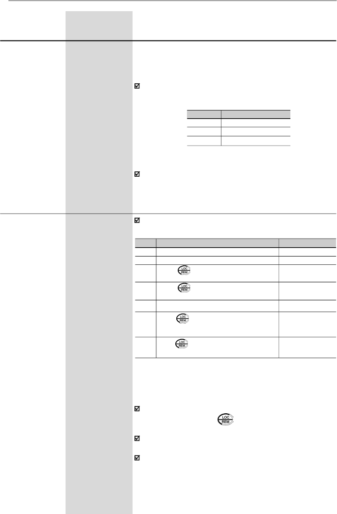
108
CHAPTER 6 - DETAILED PARAMETER DESCRIPTION
Range
[Factory Setting]
Parameter
Unit
Description / Notes
In the factory default setting, the inverter is started in lo-
cal mode and the key of the HMI-CFW08-P keypad
will select the local/remote mode.
The inverters with dummypanel (without HMI-CFW08-P
keypad) are factory supplied with P220 = 3.
For more details, refer to item 6.2.6.
P220
(3)
0 to 6
Local/Remote
[ 2 ]
Selection Source
-
Defines the source of the Local/Remote selection.
In application where it is not possible to operate the in-
verter at 2.5 kHz (for instance, due to acoustic noise),
set P219 = 0.00.
Table 6.13
- Configuration of P220 for defining where the Local/
Remote selection is made
models the switching frequency reduction at low speed
for maintaining the performance is not required. This is
possible because the output current acquisition circuit is
different in these models.
It is recommended to set P219 according to the switching
frequency as shown below:
P297 (F
sw
)
4 (5 kHz)
6 (10 kHz)
7 (15 kHz)
Recommended P219
6.00 Hz
12.00 Hz
18.00 Hz
Table 6.12
- Recommended values for P219
P220
0
1
2
3
4
5
6
Local/Remote Selection
Always local mode
Always remote mode
Key of the keypad
(HMI-CFW08-P or HMI-CFW08-RP)
Key of the keypad
(HMI-CFW08-P or HMI-CFW08-RP)
DI2 to DI4
Key of the keypad (HMI-
CFW08-RS) or serial interface
Key of the keypad (HMI-
CFW08-RS) or serial interface
Default Mode
(*)
-
-
Local
Remote
-
Local
Remote
(*)
When inverter is powered up (initialization).
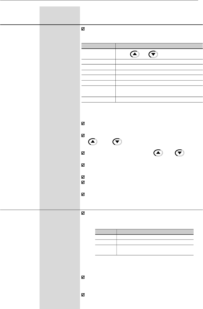
109
CHAPTER 6 - DETAILED PARAMETER DESCRIPTION
Range
[Factory Setting]
Parameter
Unit
Description / Notes
TheAI1’term is the AI1 analog input value after gain and
offset have been applied.
For factory default setting, the local reference is via the
and keys of the keypad and the remote
reference is via analog inputAI1.
The reference value set by the and keys is
contained in parameter P121.
For details of the Electronic Potentiometer (EP) operation,
refer to figure 6.20.
When option 4 (EP) is selected, set P265 and P266 to 5.
When option 6 (multispeed) is selected, set P264 and/
or P265 and/or P266 to 7.
For more details, refer to items 6.2.4 and 6.2.6.
Table 6.14
- Programming P221 (local mode) or P222 (remote
mode) for speed reference selection
P221
(3)
0 to 8
Frequency
[ 0 ]
Local Reference
-
Selection
P222
(3)
0 to 8
Frequency
[ 1 ]
Remote
-
Reference
Selection
Defines the frequency reference selection in the Local and
Remote
mode.
P221/P222
0
1
2 or 3
4
5
6
7
8
Reference Source
Keys and of the HMIs (P121)
Analog inputAI1' (P234, P235 and P236)
Analog inputAI2' (P238, P239 and P240)
Electronic potentiometer (EP)
Serial
Multispeed (P124 to P131)
Sum of the analog inputs (AI1'+AI2') 0 (negative
values are zeroed)
Sum of the analog inputs (AI1'+AI2')
The direction of rotation is the only operation control that
depends on other parameter for operation refer to the
parameter P231.
For more details, refer to items 6.2.4, 6.2.5 and 6.2.6.
P229
(3)
0 to 2
Local Command
[ 0 ]
Selection
-
P230
(3)
0 to 2
Remote
[ 1 ]
Command
-
Selection
Define the control sources for the inverter enabling and
disabling FWD/REV and JOG.
Table 6.15
- Programming P229 and P230 for
origin selection of the inverter commands
P229/P230
0
1
2
Control Source
HMI-CFW08-P or HMI-CFW08-RP Keypad
Terminals (XC1)
HMI-CFW08-RS keypad
or serial interface
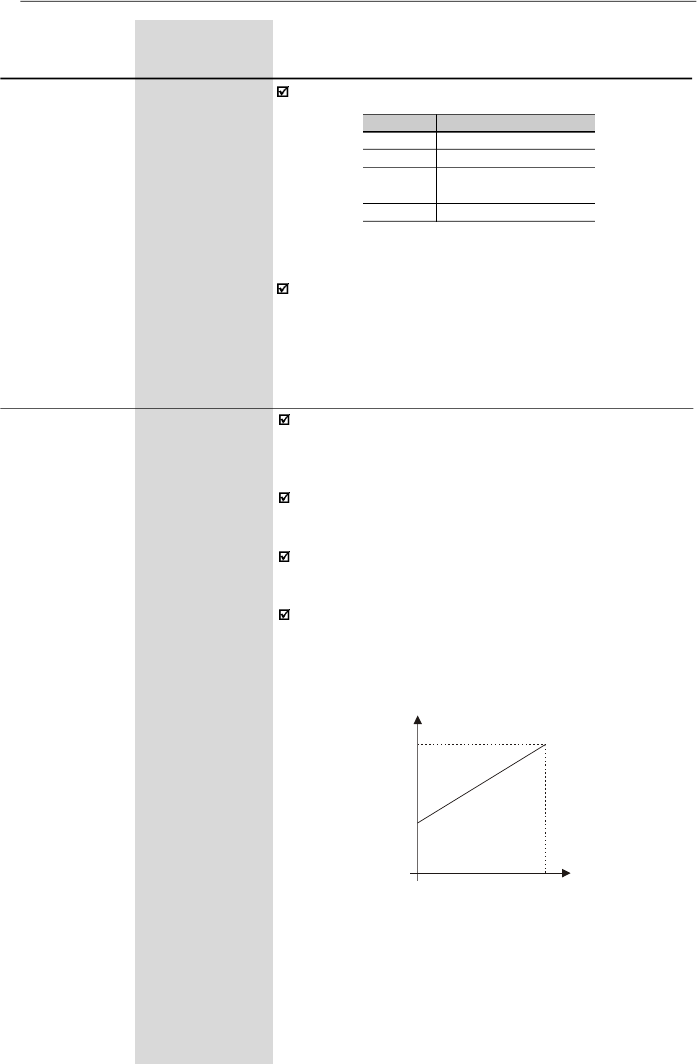
110
CHAPTER 6 - DETAILED PARAMETER DESCRIPTION
Range
[Factory Setting]
Parameter
Unit
Description / Notes
P231
(3)
0 to 3
Forward/Reverse
[ 2
]
Selection - Local
-
and Remote
Defines the direction of rotation.
Table 6.16
- Programming P231 for direction of
rotation selection
P231
0
1
2
3
Direction of Rotation
Always forward
Always reverse
Commands as defined in
P229 and P230
DIx
P233
0 or 1
Analog Input
[ 1 ]
Dead Zone
-
The dead zone removal function is helpful when the user
whishes to operate withonlya restricted range of values,
without losing the analog input resolution.
This parameter works only for analog inputs (AIx)
programmed for frequency reference.
It defines whether the analog input dead zone is:
Inactive = 0 or Active = 1.
If P233= 0 (Inactive), the signal at the analog inputsacts on
thefrequencyreferencestartingfromtheminimumfrequency
programmed at P133, up to the maximum frequency
programmed at P134, by changing the signal from 0 V/0
mA/4 mA to 10 V/20 mA,according to the figure 6.17.
P134
Reference
0
Alx Signal
P133
0
................
10 V
0
................
20 mA
4 mA
...........
20 mA
Figure 6.17 -
Analog input response with Inactive (P233 = 0)
Dead Zone
If P233 = 1 (Active), the signal at the analog inputs has a
dead zone where the frequency reference remains at the
minimum reference value (P133),even with the variation
of the input signal, according to the figure 6.18.
When P231 = 3,the DIx programmed for speed direction
in P264, P265, P266, P267 or P268 defines the Forward
speed direction when Inactive, and Reverse whenActive.
This speed direction definition prevails over any other that
may be programmed in the inverter.Opposite to the option
P231 = 2, which depends on the local or remotesituation.
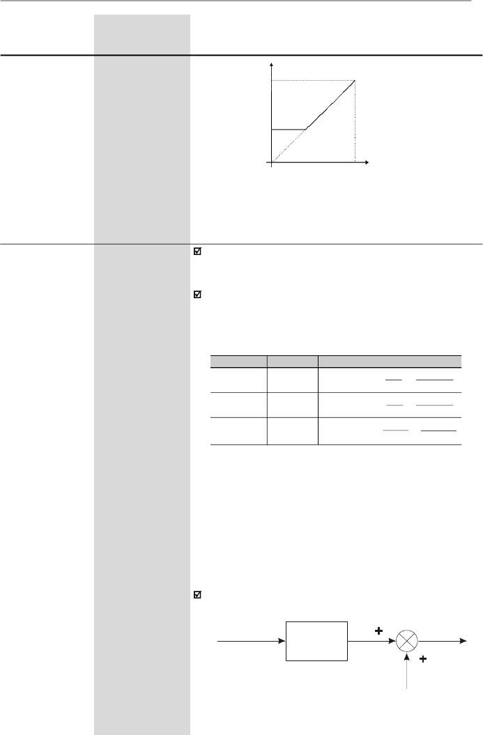
111
CHAPTER 6 - DETAILED PARAMETER DESCRIPTION
Range
[Factory Setting]
Parameter
Unit
Description / Notes
P234
0.00 to 9.99
Analog InputAI1
[ 1.00 ]
Gain
0.01
The analog inputs AI1 and AI2 define the inverter
frequency reference as shown in the curves presented in
the parameter P233 (figure 6.17 and figure 6.18).
The internal valueAIx’that definesthe frequency reference
to be used by the inverter, is given as percent of the full
scale reading and is obtained by using one of the following
equations (refer to the parameters P235 and P239):
P235/P239
0
0
1
Signal
0 to 10 V
0 to 20 mA
4 to 20 mA
Equation
AIx' =
GAIN
.
AIx
+
OFFSET
10
100
AIx' =
GAIN
.
AIx
+
OFFSET
20
100
AIx' =
GAIN
.
AIx - 4
+
OFFSET
16
100
Table 6.17
- Definition of the analog input signal
AI1 (P235) and AI2 (P239)
where:
- x = 1, 2.
- AIx is given in V or mA, according to the used signal
(refer to the parameters P235 and P239).
Figure 6.18 -
Analog input response with Active (P233 = 1) Dead
Zone
P134
Reference
0
Alx Signal
0
................
10 V
0
................
20 mA
4 mA
...........
20 mA
P133
- GAIN is defined bythe parameters P234 and P238 for
AI1 andAI2 respectively.
- OFFSET is defined by the parameters P236 and P240
forAI1 andAI2 respectively.
This is shown in the figure 6.19.
Figure 6.19
- Block diagram of the analog inputs AI1 and AI2
GAIN
P234, P238
AIx'
OFFSET
(P236, P240)
P235
P239
AIx
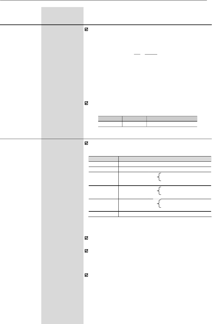
112
CHAPTER 6 - DETAILED PARAMETER DESCRIPTION
P235
(3) (5)
0 to 5
Analog InputAI1
[ 0 ]
Function
(0 to 10) V/
(0 to 20) mA
-
Defines the typeof the signal of the analog input, asshown
in table below:
Range
[Factory Setting]
Parameter
Unit
Description / Notes
Table 6.18
- Signal definition of analog inputs Al1
(P235) and Al2 (P239)
As an example,refer to the following situation:AI1 is set to
voltage input (0 to 10 V) – P235 = 0,AI1 = 5 V,P234 = 1.00
and P236 = -70 %. Thus:
The motor will run in reverse direction of rotation as
defined by the commands (negative value) - if this is
possible (P231 = 2), with a module reference equal to
0.2 or 20 % of the maximum output frequency (P134).
I.e., if P134 = 66.00 Hz, then the frequency reference is
equal to 13.2 Hz.
The following configurations areavailable for the version
“A2” of the control board:
When current signals are used, change the switch
position S1:3 and/or S1:4 to ON.
In the functions 2, 3 and 4 in P235 or P239, the analog
functionAIx leaves this function and operates as a digital
input NPN (active with lowlevel) or as a digital inputPNP
(active with high level) or as a digital input with levels TTL.
The inverter displays E24 when the signal AIx (P235 or
P239) has been configured as digital input and AIx is at
the same time an analog reference (P221/P222).
P234/P238
2.00
P236/P240
-100 %
Analog Input Signal
(-10 to +10) V
AI1'
= 1
.
5
+
(-70)
=
-0.2
=
-20 %
10 100
P235/P239
Type/Signal
E
xcursion
0
(0
to
10)
V
or
(0
to
20)
mA
or
(
-
10
to
+10)
V
1
(4
to
20)
mA
2
DI
5,6
–
PNP
Active if
AI
1,2
> 7
V
Inactive if
AI
1,2
< 3
V
3
DI
5,6
–
NPN
Active if
AI
1,2
< 3
V
Inactive if
AI
1,2
> 7
V
4
DI
5,6
–
TTL
Active if
AI
1,2
>
2
.
0
V
Inactive if
AI
1,2
<
0
.
8
V
5
PTC
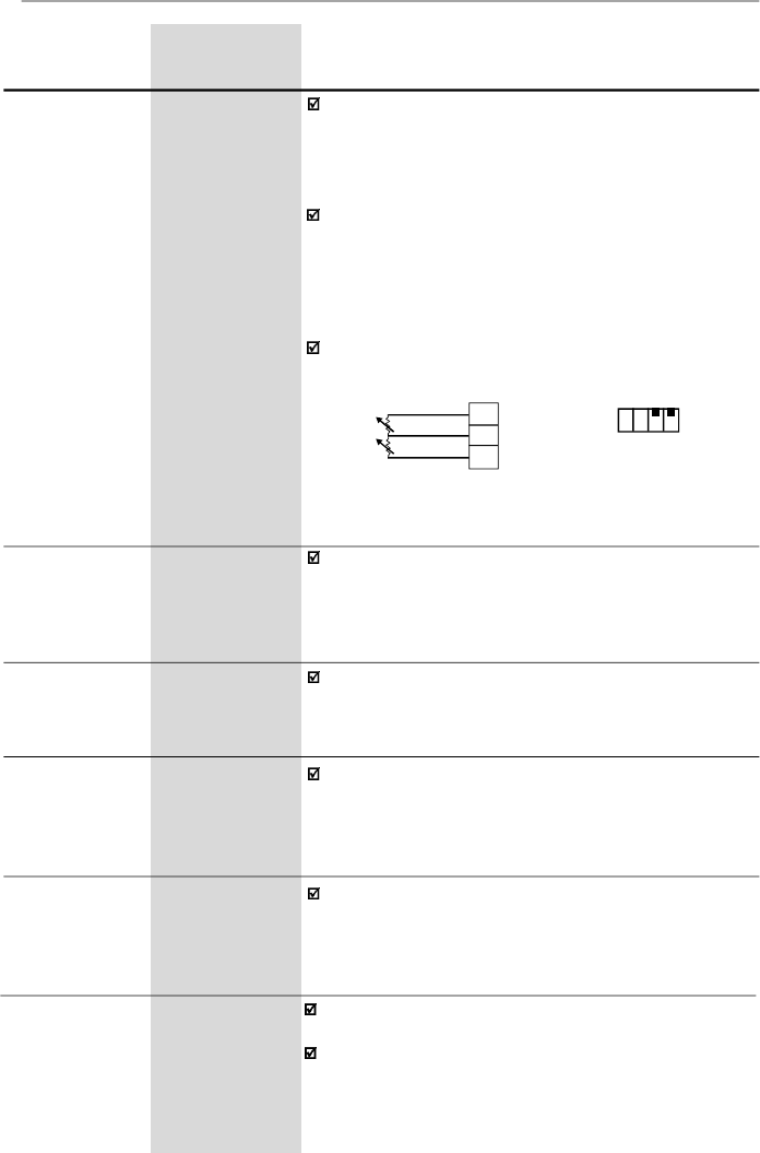
113
CHAPTER 6 - DETAILED PARAMETER DESCRIPTION
Range
[Factory Setting]
Parameter
Unit
Description / Notes
To use the bipolar option (-10 to +10) V with the version
“A2” of the control board (refer to item 2.4) the following
settings are needed:
- P234 = 2 and P236 = -50 - using AI1
- P238 = 2 and P240 = -50 - using AI2
In the option 5 in P235 or P239, the AIx can detect an
overtemperature fault (E32), through the motor PTC
detector. For this, the AIx must be configured to current
input, i. e., the DIP switch S1:3 or SI:4 must be set to
ON. The figure 6.20 shows how to make the PTC
connection to the inverter.
The two PTC inputs operate independently.
Figure 6.20
- PTC connection to the inverter
through the XC1 connector
Refer to description of P234
Refer to description of P234
P236
-999 to +999
Analog InputAI1
[ 0.0 ]
Offset
0.1 % (
99.9 %);
1 % (
100 %)
P238
(6)
0.00 to 9.99
Analog InputAI2
[ 1.00 ]
Gain
0.01
XC1
AI1
+10 V
AI2
6
7
8
S1
ON
OFF
1
2 3
4
PTC 1
PTC 2
P239
(3)(5)(6)
0 to 5
Analog InputAI2
[ 0 ]
Function
(0 to 10) V/
(0 to 20) mA
Refer to description of P235
P240
(6)
-999 to +999
Analog InputAI2
[ 0.0 ]
Offset
0.1 % (
99.9 %);
1 % (
100 %)
Refer to description of P234
P248
0 to 200
Analog Inputs
[ 10 ms ]
Filter
1 ms
Time Constant
It configures the time constant of the analog inputs filter
between 0 (without filtering) and 200 ms.
Thus the analog input will have a response time equal to
three time constants. For instance, if the time constant is
200 ms, and a step is applied to the analog input, the
response will be stabilized after 600 ms.
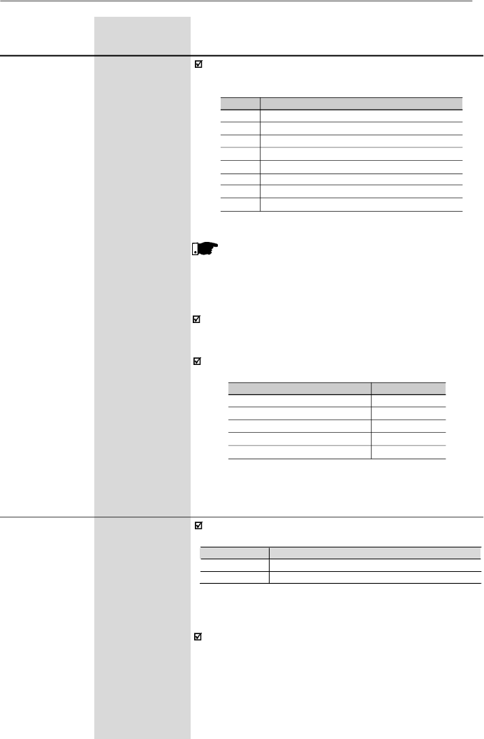
114
CHAPTER 6 - DETAILED PARAMETER DESCRIPTION
Range
[Factory Setting]
Parameter
Unit
Description / Notes
P251
(6)
0 to 9
Analog OutputAO
[ 0
]
Function
-
P252
(6)
0.00 to 9.99
Analog OutputAO
[ 1.00 ]
Gain
0.01
P251 defines the variable to be indicated at the analog
ouput according to the following table:
Table 6.19
- Configuration of P251
Table 6.20
- Full scale for possible variables that can be
represented by the AO
P251
0
1
2
3, 5 and 8
4
6
7
9
AO Function
Output frequency (Fs) - P005
Frequency reference or input frequency (Fe)
Output current - P003
No function
Torque - P009
PID Process variable - P040
Active current
PID Setpoint
NOTE!
- Option 4 is only available in the vector control mode.
- Options 6 and 9 are only available from software
version V3.50 on.
For factory setting,AO= 10 V when the output frequency
is equal to the maximum frequency (defined by P134),
i.e., equal to 66 Hz.
Indication scale at the analog outputs (full scale = 10 V):
Variable
Frequency (P251 = 0 or 1)
Current (P251 = 2 or 7)
Torque (P251 = 4)
Process Variable - PID (P251 = 6)
PID Setpoint (P251 = 9)
Full Scale
P134
1.5 x I
nom
150 %
P528
P528
P253
0 or 1
Analog Output
[ 0
]
AO Signal
-
Defines the analog output signal, as shown in table below:
Table 6.21
- Configuration of P253 to the signal type of the
analog output AO
When current signal is used, change the position of the
switches S1:2 to OFF.
P253
Type/
Signal
Excursion
0
(0
to
10)
V o
r
(0
to
20)
mA
1
(4
to
20)
mA

115
CHAPTER 6 - DETAILED PARAMETER DESCRIPTION
Check possible options in the table below and details
about the operation of the functions in the figure 6.21.
Function description:
Not used or general enable:
P263 = 0
When the command source is the terminals, i. e., if
P229 = 1
for the local mode or P230 = 1 for the remote
mode, the digital input DI1 operates as general enable.
Otherwise, no function is attributed to the input DI1
Not used or start/stop:
P265, P266, P267 or P268 = 8.
If the inverter is operating in local mode and P229 = 1,
the digital input DI3/DI4/DI5/DI6 operates as start/stop.
If the inverter is operating in remote mode and P230 = 1,
the digital input DI3/DI4/DI5/DI6 operates as start/stop.
Otherwise no function is associated to the inputs DI3/
DI4/DI5/DI6.
Multispeed:
P264, P265, P266 or P267 = 7.
You must program P221 and/or P222 = 6.
Multispeed with ramp 2
and
FWD/REV with ramp 2:
If different acceleration and deceleration times are
desired for a determined operation condition (for
instance, for a frequency set or for a direction of rotation),
please check if it is possible to use the multispeed
functions with ramp 2 and the FWD/REV with ramp 2.
Accelerates EP
and
Decelerates EP
(EP – Electronic
Potentiometer): P265 = P266 = 5 or P267 = P268 = 5.
You must program P221 and/or P222 = 4.
Local/Remote
Open/0 V at the respective digital input.
Disable Flying Start:
Refer tothe comments in the parameters P310 and P311.
Manual/Automatic:
Details aboutthisfunction can be found in the item 6.3.5
Special Function Parameters.
Range
[Factory Setting]
Parameter
Unit
Description / Notes
P263
(3)
0 to 14
Digital Input DI1
[ 0
]
Function
-
P264
(3)
0 to 14
Digital Input DI2
[ 0
]
Function
-
P265
(3) (7)
0 to 16
Digital Input DI3
[ 10
]
Function
-
P266
(3)
0 to 16
Digital Input DI4
[ 8 ]
Function
-
P267
(3) (5)
0 to 16
Function of the
[11 ]
Digital Input DI5
-
P268
(3) (5) (6)
0 to 16
Function of the
[11 ]
Digital Input DI6
-

116
CHAPTER 6 - DETAILED PARAMETER DESCRIPTION
Table 6.22
- Programming the DI’s functions
NOTE!
Functions are activated with 0 V at the digital input
when S1:1 is OFF.
Functions are activated with 24 V at the digital input
when S1:1 is ON.
Range
[Factory Setting]
Parameter
Unit
Description / Notes
DI Parameter
Function
DI1
(P263)
DI2
(P264)
DI3
(P265)
DI4
(P266)
DI5
(P267)
DI6
(P268)
General
E
nable
1
to
7
and
10
to
12
-
2
2
2
2
Start/Stop
9
-
9
9
9
9
No Function
and General
Enable
0
-
-
-
-
-
No Function
or
Start/Stop
-
-
8
8
8
8
FWD
8
-
-
-
-
-
REV
-
8
-
-
-
-
FWD with
R
amp 2
13
-
-
-
-
-
REV with
R
amp 2
-
13
-
-
-
-
ON
14
-
-
-
-
-
OFF
-
14
-
-
-
-
Multispeed
-
7
7
7
7
-
Multispeed with
R
amp 2
-
-
14
-
-
-
Increase
E
.P.
-
-
5
-
5
-
Decrease
E
.P.
-
-
-
5
-
5
FW
D/REV
-
0
0
0
0
0
Local/Remote
-
1
1
1
1
1
JOG
-
-
3
3
3
3
No
E
xternal
F
ault
-
-
4
4
4
4
Ramp 2
-
-
6
6
6
6
Reset
-
-
10
10
10
10
Disable Flying Start
-
-
13
13
13
13
Manual/Automatic (PID)
-
-
15
-
-
-
Not
U
sed
-
2
to
6
and
9
to
12
11
and
12
11,
12,
14
and
15
11, 12,
14
and
15
7, 11,
12, 14
and
15
Increase
E
.P. with
R
amp 2
-
-
16
-
16
-
Decrease
E
.P. with
R
amp 2
-
-
-
16
-
16
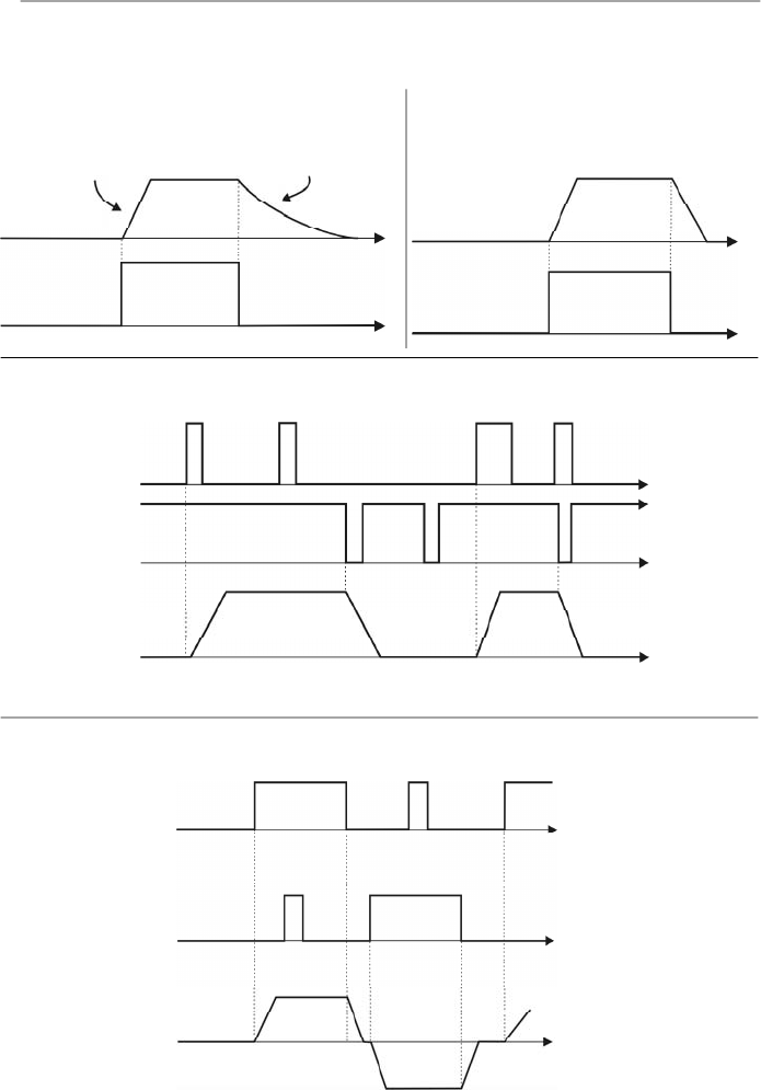
117
CHAPTER 6 - DETAILED PARAMETER DESCRIPTION
The charts below give provide actuation and operating
description of the digital input functions.
Open
Output
Frequency
(
Motor
Speed)
Motor Runs
Freely
Time
Time
0 V
Acceleration
Ramp
a) GENERAL ENABLE
D I
0 V
Deceleration
Ramp
Time
Time
Acceleration
Ramp
Open
b) START/STOP
D I
Time
Time
0 V
0 V
Open
DI2 - Stop
c) START/STOP
Time
Time
DI1 -Start
Open
Figure 6.21 a) to d)
- Time diagrams of the digital input functions
Open
Time
0 V
Time
Time
0 V
Open
DI2 - REV
DI1 - FWD
CW
CCW
d) FORWARD / REVERSE
Output
Frequency
(Motor
Speed)
Output
Frequency
(Motor
Speed)
Output
Frequency
(Motor
Speed)
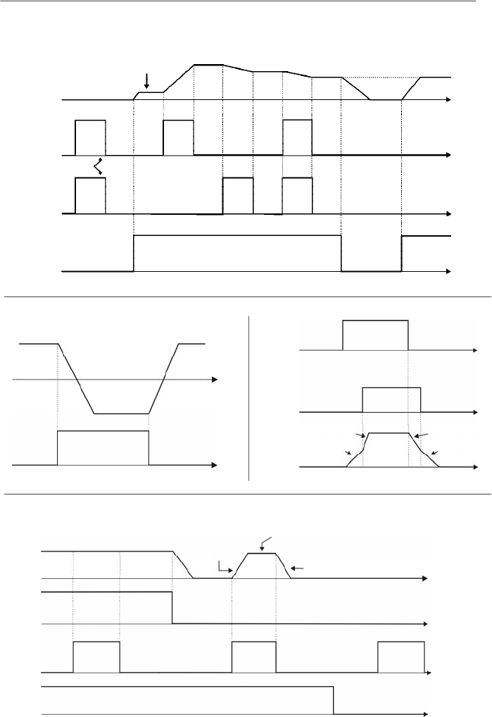
118
CHAPTER 6 - DETAILED PARAMETER DESCRIPTION
Time
Output
Frequency
(Motor Speed)
0 V
Open
DI - Start/Stop
Minimum
Frequency
(P133)
Reset
DI4 - Decrease
DI3 - Increase
Open
Time
Time
Time
0 V
0 V
e) ELECTRONIC POTENTIOMETER (EP)
Open
Open
0 V
Time
Time
Output
Frequency
(Motor
Speed)
DI - FWD/
REV
CW
CCW
f) FWD/REV
Open
Open
0 V
Time
0 V
Time
P102
P100
DI - Start/Stop
DI - Ramp 2
g) RAMP 2
P103
P101
Time
Figure 6.21 (cont.) e) to h)
- Time diagrams of the digital input functions
Time
Output
Frequency
(Motor
Speed)
0 V
0 V
Start/Stop
JOG Frequency
(P122)
Deceleration
Ramp
0 V
DI - JOG
General
Enabling
Open
Open
Open
Acceleration
Ramp
h) JOG
Time
Time
Time
Output
Frequency
(Motor Speed)
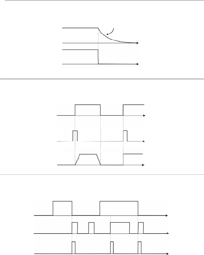
119
CHAPTER 6 - DETAILED PARAMETER DESCRIPTION
j) FLYING START DISABLE
Figure 6.21 (cont.) i) to k)
- Time diagrams of the digital input functions
k) RESET
Time
Disabled
0 V
Enabled
Inverter
Status
DI - Flying
Start Disable
Time
Time
Fault (Exy)
Time
0 V
Time
Time
0 V
No Error
Reset
DI - Reset
Open
Inverter
Status
(*)
(*)
The condition that generated the fault persists.
Open
0 V
Time
Time
DI - No External Fault
i) NO EXTERNAL FAULT
Motor Runs
Freely
Output
Frequency
(Motor Speed)
Output
Frequency
(Motor Speed)
Open

120
CHAPTER 6 - DETAILED PARAMETER DESCRIPTION
Notesabout the functions of the relayoutputs:
1)
When the definition in the function name is true, the
digital output will be activated, i.e., the relay coil is
energized.
2)
When the option 'Not used' has been programmed,
the relay output(s) will be disabled, i.e., the coil is not
energized.
3)
CFW-08 Plus has 2 relay outputs (1 NO and 1 NC
contact). It is possible to emulate a reversal contact
relay by setting P277 = P279.
Definitions of the symbols used in the functions:
-
Fs
= P005 - Motor Output Frequency
-
Fe
= Frequency Reference (ramp inputfrequency)
-
Fx
= P288 - Fx Frequency
-
Is
= P003 - Motor Output Current
-
Ix
= P290 - Ix Current
Range
[Factory Setting]
Parameter
Unit
Description / Notes
P277
(3)
0 to 7
Relay Output RL1
[ 7 ]
Function
-
P279
(3) (6)
0 to 7
Relay Output RL2
[ 0
]
Function
-
Check possible options on table below.
Output/Parameter
Function
Fs > Fx
Fe > Fx
Fs = Fe
Is > Ix
Not used
Run (inverter enabled)
No fault
P277
(RL1)
0
1
2
3
4 and 6
5
7
P279
(RL2)
0
1
2
3
4 and 6
5
7
Table 6.23
- Functions of the relay outputs
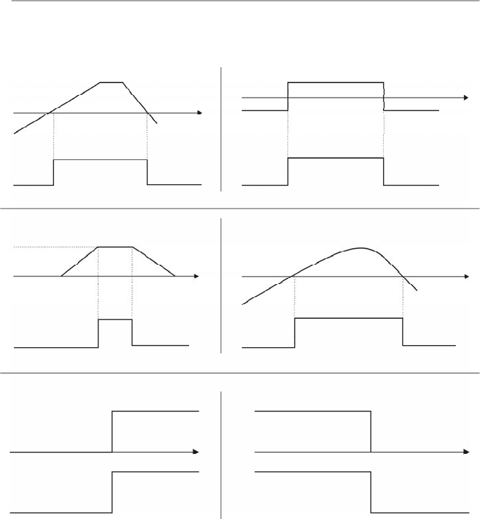
121
CHAPTER 6 - DETAILED PARAMETER DESCRIPTION
Figure 6.22 a) to f)
- Details about the operation of the digital relay output functions
a) Fs > Fx
Fs
Fx (P288)
Time
OFF
Relay
ON
d) Is > Ix
Is
Ix (P290)
Time
OFF
Relay
ON
c) Fs = Fe
Fs
Time
OFF
Relay
ON
Fe
Fx (P288)
Time
OFF
Relay
ON
b) Fe > Fx
e) Run
Stopped Motor or
Running by Inertia
Time
OFF
Relay
ON
Motor Running
f) No Fault
Time
OFF
Relay
Fault State (Exy)
Ready/Run State
ON
The charts below give provide actuation and operating
description of the relay output:
without E0X
Fe
Is
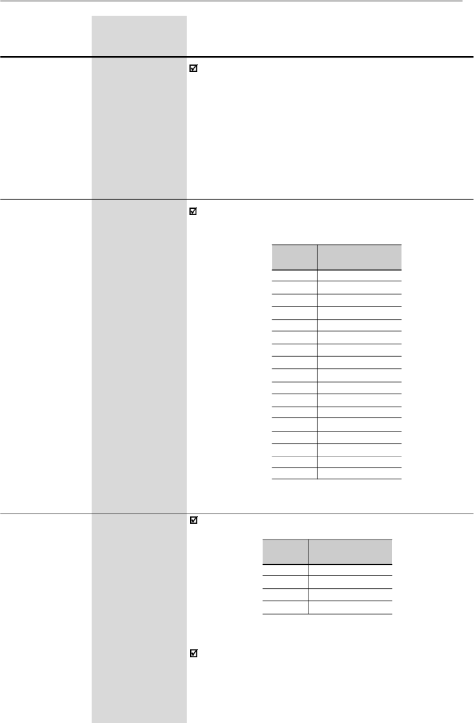
122
CHAPTER 6 - DETAILED PARAMETER DESCRIPTION
Range
[Factory Setting]
Parameter
Unit
Description / Notes
P288
0.00 to P134
Fx Frequency
[ 3.00 Hz
]
0.01Hz(
99.99Hz);
0.1 Hz (
100.0 Hz)
P290
0 to 1.5xI
nom
IxCurrent
[ 1.0xI
nom
]
0.01 A (
9.99 A);
0.1 A (
10.0 A)
Used in the relay output functions Fs > Fx, Fe > Fx and
Is > Ix (refer to the parameters P277 and P279).
P295
(3)
300 to 316
Rated Inverter
[According to the
Current(I
nom
)
rated inverter
current (I
nom
)]
-
P295
300
301
302
303
304
305
306
307
308
309
310
311
312
313
314
315
316
Rated Inverter
Current (I
nom
)
1.0 A
1.6 A
2.6 A
2.7 A
4.0 A
4.3 A
6.5 A
7.0 A
7.3 A
10 A
13 A
16 A
22 A
24 A
28 A
30 A
33 A
Table 6.24
- Definition of the rated inverter current
The rated inverter current can be programmed according
to the table below.
P297
(3)
4 to 7
Switching
[ 4 ]
Frequency
kHz
DefinestheswitchingfrequencyoftheIGBTsinthe inverter.
The switching frequency is a compromise between the
motor acoustic noise level and the inverters
IGBTs
losses.
Higher switching frequencies cause lower motoracoustic
noise level, but increase the
IGBTs
losses
,
increasing the
P297
4
5
6
7
Switching
Frequency (f
sw
)
5 kHz
2.5 kHz
10 kHz
15 kHz
Table 6.25
- Definition of the switching frequency

123
CHAPTER 6 - DETAILED PARAMETER DESCRIPTION
Range
[Factory Setting]
Parameter
Unit
Description / Notes
drive components temperature and thus reducing their
useful life.
The predominant frequency on the motor is twice the
switching frequencyset at P297.
Thus, P297 = 4 (5 kHz) results in an audible motornoise
corresponding to 10 kHz. This is due to the used PWM
technique .
The reduction of the switching frequency also contributes
to the reduction of instability and ressonance that may
occur in certain application conditions, as well as reduces
the emission of electromagnetic energy by the inverter.
The reduction of the switching frequencies also reduces
the leakage currents to ground, which may avoid the
nuisance activation of the ground fault protection (E00).
The option 15 kHz (P297 = 7) is not available in vector
control mode or when the external serial keypad (HMI-
CFW-08-RS) is used.
Use currents according to table below:
Inverter Model
CFW080016S2024 ...
CFW080016B2024 ...
CFW080026S2024 ...
CFW080026B2024 ...
CFW080040S2024 ...
CFW080040B2024 ...
CFW080070T2024 ...
CFW080073B2024 ...
CFW080100B2024 ...
CFW080160T2024 ...
CFW080220T2024...
CFW080280T2024...
CFW080330T2024...
CFW080010T3848 ...
CFW080016T3848 ...
CFW080026T3848 ...
CFW080027T3848 ...
CFW080040T3848 ...
CFW080043T3848 ...
CFW080065T3848 ...
CFW080100T3848 ...
CFW080130T3848 ...
CFW080160T3848 ...
CFW080240T3848...
CFW080300T3848...
10 kHz
(P297 = 6)
1.6 A
1.6 A
2.6 A
2.6 A
4.0 A
4.0 A
7.0 A
7.3 A
10 A
14 A
18A
22A
25A
1.0 A
1.6 A
2.6 A
2.7 A
3.6 A
3.9 A
6.5 A
8.4 A
11 A
12 A
15A
16A
15 kHz
(P297 = 7)
1.6 A
1.6 A
2.1 A
2.6 A
3.4 A
4.0 A
6.3 A
7.3 A
10 A
12 A
15 A
18A
21A
1.0 A
1.6 A
2.3 A
2.7 A
2.8 A
3.0 A
6.3 A
6.4 A
9 A
10 A
12A
13 A
2.5 kHz
(P297 = 5)
1.6 A
1.6 A
2.6 A
2.6 A
4.0 A
4.0 A
7.0 A
7.3 A
10 A
16 A
22 A
28A
33A
1.0 A
1.6 A
2.6 A
2.7 A
4.0 A
4.3 A
6.5 A
10 A
13 A
16 A
24A
30A
5 kHz
(P297 = 4)
1.6 A
1.6 A
2.6 A
2.6 A
4.0 A
4.0 A
7.0 A
7.3 A
10 A
16 A
22 A
28A
33A
1.0 A
1.6 A
2.6 A
2.7 A
4.0 A
4.3 A
6.5 A
10 A
13 A
16 A
24A
30A
Table 6.26
- Current values for P297
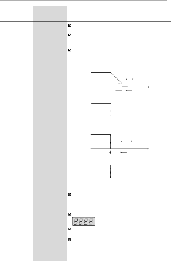
124
CHAPTER 6 - DETAILED PARAMETER DESCRIPTION
Range
[Factory Setting]
Parameter
Unit
Description / Notes
P300
0.0 to 15.0
DC Braking
[ 0.0
]
Time
0.1 s
P301
0.00 to 15.00
DC Braking
[ 1.00 Hz
]
Start Frequency
0.01 Hz
P302
0.0 to 130
DC Braking
[ 0.0 %
]
Current
0.1 %
The DC braking feature provides a motor fast stop via
DC current injection.
The applied DC braking current, that is proportional to
the braking torque, is set at
P302
, and is adjusted as a
percentage (%) relating to the rated inverter current.
The figures below showthe DC braking operation at the
two possible conditions
:
ramp disabling and general
disabling
.
Figure 6.23
- DC braking after ramp disabling
P301
P300
DEAD
TIME
Open
Time
DI - Start/Stop
0 V
DCCURRENT
INJECTION
Motor Speed
Output Frequency
P300
Open
Time
DEADTIME
DCCURRENT
INJECTION
DI - General Enable
Figur
e
6.2
4
-
DC braking after general disabling
Motor Speed
Output Frequency
0 V
Before DC braking starts, there is a "dead time" (motor
runs freely) required for the motor demagnetization. This
time is function of the motor speed at which the DC
braking occurs.
During the DC braking the LED display flashes:
If the inverter is enabled during the braking process, this
process will be aborted and motor operates normally.
DC braking can continue its braking process even after
the motor has stopped. Pay special attention to the
dimensioning of the motor thermal protection for cyclic
braking of short times.
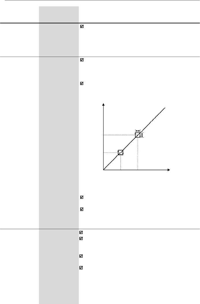
125
CHAPTER 6 - DETAILED PARAMETER DESCRIPTION
Range
[Factory Setting]
Parameter
Unit
Description / Notes
P304
P133 to P134
Skip Frequency 2
[ 30.00 Hz
]
0.01 Hz
(
99.99 Hz);
0.1 Hz
(
100.0 Hz)
P306
0.00 to 25.00
Skip Band Range
[ 0.00
]
0.01 Hz
Figure 6.25
- Skip frequency curves
P303
P133 to P134
Skip Frequency 1
[ 20.00 Hz
]
0.01 Hz
(
99.99 Hz);
0.1 Hz
(
100.0 Hz)
This feature (skip frequencies) prevents the motor from
operating permanently at speeds where the mechanical
system enters into
resonance,causing high vibration or
noise levels.
The enabling of this function is performed by setting
P306
0.00.
2 x P306
P303
P304
P303
P304
2 x P306
Frequency
Reference
Output Frequency
The passage through the skip frequency band (2xP306)
uses the programmed acceleration/deceleration ramps.
This function does not work properly if two skip
frequencies overlap.
In applications where the motor current is lower than the
rated inverter current, and where the braking torque is
not enoughfor the braking condition, please contactWEG
to optimize the settings.
P308
(3)
1 to 30
InverterAddress
(WEG Protocol)
1 to 247
(Modbus-RTU)
[ 1
]
1
Setstheaddressoftheinverterfortheserialcommunication.
Maximum allowable value for WEG serial protocol is 30
and maximum allowable value for Modbus-RTU protocol
is 247.
For more details about the Serial communication refer
to the item 8.24 and 8.25.
The serial interface is an optional inverter accessory.
Refer to the items 8.11, 8.12 and 8.16 for detailed
information.

126
CHAPTER 6 - DETAILED PARAMETER DESCRIPTION
Range
[Factory Setting]
Parameter
Unit
Description / Notes
P310
(3)
0 to 3
Flying Start and
[ 0
]
Ride-Through
-
P311
0.1 to 10.0
Voltage Ramp
[ 5.0 s ]
0.1 s
The parameter P310 selects the active function(s):
P310
0
1
2
3
Flying Start
Inactive
Active
Active
Inactive
Ride-Through
Inactive
Inactive
Active
Active
Parameter P311 sets the time required for the motor
restart, both
for
F
lying
S
tart function and the
R
ide-
T
hrough
function.Inotherwords, it
defines the time to set the output
voltage starting from 0 V and up to reaching the rated
voltage.
Operation of the Flying Start function:
-
It allows the motor to start when it is running. This
functions acts only when the inverter is enabled.During
the start, the inverterwill impose the speed reference,
creating a voltage ramp with time defined at P311.
-
The motor can be started in conventional form, even
when the Flying Start has been selected(P310 = 1 or2),
adjusting one of the digital inputs (DI3 or DI4) to 13
(Flying Start disable) and driving it (0 V) during the
motor start.
Ride-Through operation:
-
Permits the inverterrecovery, without disabling byE02
(undervoltage), when a momentaryvoltage drop in the
line occurs.
The inverter will be disabled only by E02, if the voltage
drop is longer than 2.0 s.
-
When the Ride-Through function is enabled (P310 = 2
or 3)
and if a voltage drop in the line occurs, so the link
circuit voltage becomes lower than the permitted
undervoltage level, the output pulses will be disabled
(motor
runs freely
)
and the inverter waits up to 2 s for
the line re-establishment. If the line returns to its normal
status within this time, the inverter will enable again
the PWM pulses, imposing the frequency reference
instantaneously and providing a voltage ramp with time
defined at P311.
-
There is a dead time before this voltage ramp is
started, required for the motor demagnetization. This
time is proportional to the output frequency (motor
speed).
Table 6.27
-
Activation of the function Flying Start and Ride-Through
by the parameter P310
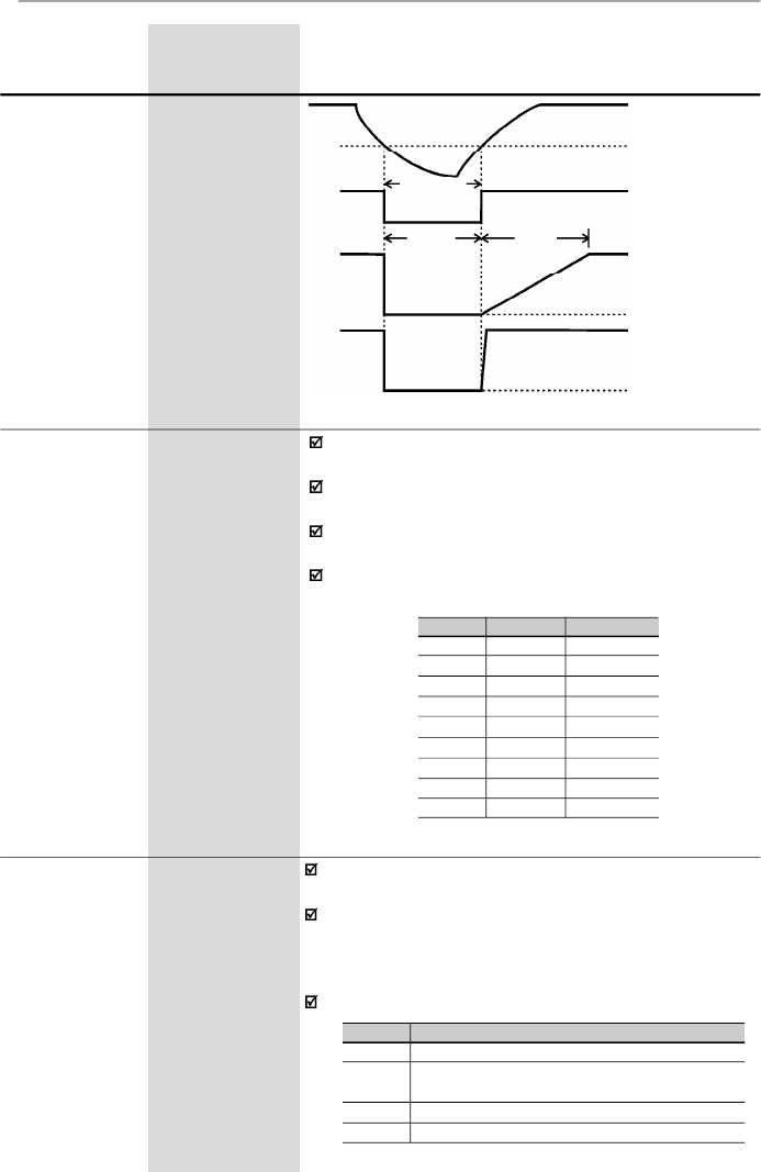
127
CHAPTER 6 - DETAILED PARAMETER DESCRIPTION
Range
[Factory Setting]
Parameter
Unit
Description / Notes
Figure 6.26
- Ride-Through actuation
P311
t < 2s
t
disabled
>t
dead
time
Enabled
Disabled
DC Link Voltage
Undervoltage Level
(E02)
PWM pulses
Output Voltage
0 V
Output Frequency
(Motor Speed)
0 Hz
It sets the type of the protocol for the serial
communication.
The serial interface can be configured for two distinct
protocols: WEG and Modbus-RTU.
The WEG protocol is described in item 8.24 and is
selected by setting P312 = 0.
The Modbus-RTU protocol, described in item 8.25 has
nine predefined formats, as shown in table below:
P312
1
2
3
4
5
6
7
8
9
Rate (bps)
9600
9600
9600
19200
19200
19200
38400
38400
38400
Parity
-
Odd
Even
-
Odd
Even
-
Odd
Even
P312
(3)
0 to 9
Serial Interface
[0
- WEG ]
Protocol
1
Table 6.28
- P312 configuration for Modbus-RTU protocol formats
It determines the type of action performed by the
Watchdog.
If the inverter does not receive any valid message (via
serial interface) during the interval programmed at P314,
the action set at P313 will be performed and error E28
is shown on the display.
The different actions are:
P313
0 to 3
Serial Interface
[ 2 ]
WatchdogAction
1
Table 6.29
-
Configuration of P313 to Watchdog actions
Action
Disables inverter via deceleration ramp
Triggers the general disable command of the
inverter
Indicates only E28
Changes the command reference to local mode
P313
0
1
2
3

128
CHAPTER 6 - DETAILED PARAMETER DESCRIPTION
Range
[Factory Setting]
Parameter
Unit
Description / Notes
If the communication is re-established, E28 switches off
and the inverter does not change its status.
Actuation interval of the Serial Watchdog. If the value of
P314 is equal to 0, the Serial Watchdog function is
disabled. Otherwise, if the inverter does not receive any
valid message during this interval, it assumes the action
that has been programmed at P313.
P314
0.0 to 99.9
Serial Interface
[ 0.0 ]
WatchdogTimeout
0.1 s
P399
(1) (3)
50.0 to 99.9
Rated Motor
[ according to the
Efficiency
inverter model ]
0.1 %
Set this parameter according to motor nameplate.
If this data are not available:
-
If the rated motor power factor is known
(cos
= P407),
determine the efficiencyby the following equation:
Where:
-
P
is the motor power in (HP) (to convert HP to W multiply
by 750, i. e., 1 HP=750 W).
-
V
is the rated motor line voltage in Volts (V) – P400
-
I
is the rated motor current in Amperes (A) – P401
- For an approximation, use the values of the table in
item 9.3 of this manual.
It is used only in Vector Control mode.
6.3.4
Motor Parameters - P399 to P499
P399 =
nom
= 433 x
P
V
x
I
x
cos
P400
(1) (3)
0 to 600
Rated Motor
[ according to the
Voltage
inverter model
and
market ]
1 V
Rated motor voltage indicated on the motor nameplate.
It is the rms-value of the motor line voltage.
Set this parameter according to the motor nameplate
data and the connection diagram in the terminal box.
This parameter is used only in Vector Control mode.
P401
0.3xP295 to
Rated Motor
1.3xP295
Current
[ according to
the inverter
model ]
0.01 A (
9.99 A);
0.1 A (
10.0 A)
Rated motor current indicated on the motor nameplate.
It is the rms-value of the rated motor line current.
Set this parameter according tothe motor nameplate data
and the connection diagram in the terminal box.
This parameter is used in V/F control
[
slip compensation
function and automatic torque
boost
function (automatic
IxR)]
and vector control.

129
CHAPTER 6 - DETAILED PARAMETER DESCRIPTION
Range
[Factory Setting]
Parameter
Unit
Description / Notes
P402
(1)
0 to 9999
Rated Motor
[ according to
Speed
the inverter
model ]
1 rpm
Set this parameter according to the motor nameplate
data.
This parameter is used only in Vector Control mode.
P403
(1) (3)
0.00 to P134
Rated Motor
[ 50.00 Hz or
Frequency
60.00 Hz
depending on
the market ]
0.01 Hz
(
99.99 Hz);
0.1 Hz
(
100.0 Hz)
Set this parameter according to the motor nameplate
data.
This parameter is used only in Vector Control mode.
P404
(1) (3)
0 to 17
Rated Motor
[According to
Power
the inverter
model ]
-
Set this parameter according to motor nameplate, as
shown in table below.
P404
0
1
2
3
4
5
6
7
8
9
10
11
12
13
14
15
16
17
CV
0.16
0.25
0.33
0.5
0.75
1
1.5
2
3
4
5
5.5
6
7.5
10
12.5
15
20
HP
0.16
0.25
0.33
0.5
0.75
1
1.5
2
3
4
5
5.5
6
7.5
10
12.5
15
20
kW
0.12
0.18
0.25
0.37
0.55
0.75
1.1
1.5
2.2
3.0
3.7
4.0
4.5
5.5
7.5
9.2
11.2
15
Rated Motor Power
Table 6.30
- Configuration of the value of P404 according to the
rated motor power
This parameter is used only in Vector Control mode.
130
CHAPTER 6 - DETAILED PARAMETER DESCRIPTION
Range
[Factory Setting]
Parameter
Unit
Description / Notes
P407
(3)
0.50 to 0.99
Rated Motor
[According to
Power Factor
the inverter
model ]
0.01
Set this parameter according to motor nameplate.
If this value is not available:
- If the rated motor efficiency is known (
nom
= P399),
obtain the power factor through the following equation:
P
P407 = cos = 433 x
V x I x
nom
Where:
-
P
is the motor power in (HP) (to convert HP to W multiply
by 750, i. e., 1 HP = 750 W).
-
V
is the rated motor line voltage in Volts (V) – P400
-
I
is the rated motor current in Amperes (A) – P401
- For an approximation,use the valuesof the table in item
9.3 of this manual.
This parameter is used in V/F control [slip compensation
function and automatic torque boost function (automatic
IxR)] and vector control.
P409
(3)
0.00 to 99.99
Motor Stator
[According to
Resistance
the inverter
model ]
0.01
Value estimated by the self-tuning routine.
The table in item 9.3 shows the stator resistance for
standard, IV pole, 60 Hz, 220/380 V motors.
The value of the stator resistance can also be entered at
P409 directly, if this value is known.
NOTE!
P409 shall contain the equivalent value of the stator
resistance of one phase, bysupposing that the motor
is star connected (Y).
NOTE!
If the value of P409 is too high for the motor, a disabling
of the inverter can occur due to overcurrent (E00).
Through this parameter youcan run the self-tuning routine,
where the stator resistance of the used motor is estimated
automaticalyby the inverter.
The motor will not run.
By setting P408 = 1, the self-tuning routine is started.
During the running of the self-tuning routine, the display
flashes .
If the interruption of the self-tuning routine is desired,
press
.
If the estimated value of the motor stator resistance is
too high for
the applied inverter (examples: motor is not
connected or motor is too small forthe inverter) the inverter
displays E14. You can only exit from this condition by
switching off the inverter.
P408
(1) (3)
0 or 1
Run Self-Tuning
[ 0
]
-

131
CHAPTER 6 - DETAILED PARAMETER DESCRIPTION
setpoint (%) =
setpoint (UP)
x P234 x 100 %
full scale of the used sensor (UP)
6.3.5
Special Function Parameters - P500 to P599
6.3.5.1
Introduction
CFW-08 is fitted with the PID regulator that can be used
for closed loop process control. This function acts as a
proportional, integral and derivative regulator,
superimposed on the normal inverter speed control.
The speed will be changed in order to maintain the process
variable (the variable thatshould be controlled - forinstance:
water level of a container) at the desired value, set in the
setpoint.
This regulator can, for instance, control the flow in a piping
system. The setpoint (flow) can be given bythe analog input
AI2 or through P525 (digital setpoint), and the flowfeedback
signal is given at analog inputAI1.
Other application examples: level control, temperature
control, dosing control, etc.
Figure 6.27 shows the block diagram of the PID regulator.
The feedback signal must be sent to the analog inputAI1.
The setpoint is the value of the process variable at which
the operation is desired. This value is entered as a
percentage and is defined by the following equation:
6.3.5.2
Description
Both the setpoint and the full scale value of the sensor are
given by the process unit (°C, bar, etc.).
Example: a pressure transducer (sensor) with output 4 -
20 mA and full scale of 25bar(i.e., 4 mA = 0 barand 20 mA
= 25 bar) and P234 = 2.00. If the control of 10bar is desired,
you should enter the following setpoint:
setpoint (%) =
10
x 2 x 100 % = 80 %
25
The setpoint can be defined via:
-
Keypad: digital setpoint, parameter P525.
-
Analog inputAI2 (only available in the CFW-08 Plus):
the percentage value is determined by considering
P238, P239 and P240 (refer to description of these
parameters).

132
CHAPTER 6 - DETAILED PARAMETER DESCRIPTION
Example: consider the data of the last example (pressure
sensor of 0-25bar and P234 = 2.00) . P528 must be set to
25/2 = 12.5.
The parameter P040 can be selected as the displaydefault
parameter P205 = 6.
P528 =
full scale value of the used sensor
P234
The parameter P040 indicates the value of the process
variable (feedback) in the scale selected at P528, that is
set according to the following equation:
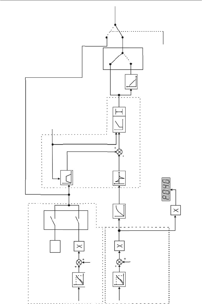
133
CHAPTER 6 - DETAILED PARAMETER DESCRIPTION
Manual
(DI open)
Frequency
Reference
(Speed)
Automatic
(DI closed)
Fe(
refer to
figure
6.2)
Setpoint Definition
(reference of the
process variable)
AI2
P239
AI2
Signal
P240
(AI2 Offset)
AI2 Gain
P525
2, 3 - AI2
0-Key
P221 (Local) or
P222 (Remote)
PID Setpoint (Key)
Setpoint
PID Regulator
PID Ramp
P526
Process
Variable Filter
P528
Process
Variable
Scale Factor
P235
AI1
Signal
AI1
P236
(AI1 Offset)
AI1 Gian
P238
P234
Feedback
(measurement of the
process variable)
P522
Differential
Regulator
P520, P521
PI Regulator
(Proportional - Integral)
P134
P133
1-Revers
al
0-Direct
PID Action Type
DI3
(P265 = 15)
F* (refer to fig 6.1)
P527
Enabling Command
Figure 6.27
- Block diagram of the PID regulator function
0.2s

134
CHAPTER 6 - DETAILED PARAMETER DESCRIPTION
6.3.5.3
PID Start-up Guide
Please find below a start-up procedure for the PID regulator:
Initial Definition
1)
Process - Definition of the PID action type that the
process requires: direct or reverse. The control action
must be direct(P527 = 0) when it is required to increase
the motor speed and so also increment the process
variable. Otherwise select reverse (P527 = 1).
Examples:
a)
Direct: pump driven by inverter and filling a tank
where the PID regulates the tank level. To increase
the level height (process variable) the flow must be
increased and consequently also the motor speed
must be increased.
b)
Reverse: fan driven by an inverter to cool a cooling
tower, with the PID controlling the temperature of this
tower. When it is required to increase the tower
temperature (process variable), the cooling power
must be decreased by reducing the motor speed.
NOTE!
When the PID function (P203 = 1) is set:
The digital input DI3 is automatically set to manual/
automatic(P265 = 15). Thus when DI3 is open,the manual
mode is activated and when DI3 is closed, the PID regulator
starts to operate (closed loop control - automatic mode).
If the function of this digital input (DI3) is changed, the
operation of the inverter will be always in manual mode.
If P221 or P222 is equal to 1, 4, 5, 6, 7 or 8 the E24 error
message will be displayed. Set P221 and P222 equal to 0
or 2 according to the requirement.
The JOG and the FWD/REV functions are disabled. The
inveter enabling and disabling commands are defined by
P229 and P230.
In the manual mode, the frequency reference is given by
F*, as shown in figure 6.1.
When the operation mode is changed from manual to
automatic, P525 is automatically set to the value of P040
if P536 = 0 (at the instant immediately before the
commutation). Thus when the setpoint is defined by P525
(P221 or P222 = 0), the changing from manual to automatic
is smooth [there is not abrupt oscillation in the frequency
(speed) reference].
The analog output can be programmed to indicate the
process variable (P040) or the PID setpoint with P251 = 6
or 9, respectively.
Figure 6.28 shows an application example of an inverter
controlling a process in closed loop (PID regulator).

135
CHAPTER 6 - DETAILED PARAMETER DESCRIPTION
2)
Feedback (process variable measurement): the feeback
is always realized via analog inputAI1.
Transducer (sensor) to be used for the feedback of the
control variable: it is recommended to use asensor with
full scale with at least 1.1 times higher than the largest
value of the process variable that shall be controlled.
Example: if a pressure control at 20 bar is desired, select
a sensor with a control capacity of at least 22 bar.
Signal type: set P235 and the position of the switch S1
on the control board according to the transducer signal
(4 -20 mA, 0 -20 mA or 0 -10 V).
Set P234 and P236 according to the variation range of
the used feedback signal (for more details, refer to
description of the parameters P234 to P240).
Example: suppose the following application:
-
Full scale of the transducer (maximum value at the
transducer output) = 25 bar (FS = 25).
-
Operation range (range of interest) = 0 to 15 bar
(FO = 15).
Considering a safety margin of 10 %, the measuring ran-
ge of the process variable must be set to: 0 to 16.5 bar.
Thus: FM = 1.1 x FS = 16.5.
Parameter P234 must be set to:
P234 =
FS
=
25
= 1.52
FM
16.5
As the operation range starts at zero, P236 = 0, thus a
setpointof 100 % represents 16.5 bar, i.e., the operation
range, in percentage, is within: 0 to 90.9 %.
NOTE!
In the most cases it is not necessary to set the gain and the
offset (P234 = 1.00 and P236 = 0.0). Thus the percentage
value of the setpoint is equivalent to the percentage value of
the full scale of the used sensor. However if the maximum
resolution of the analog input AI1 (feedback) is desired, set
P234 and P238 according to comments above.
Setting of the display indication to the process variable
measuring unit (P040): set P528 according to the full scale of
the used transducer (sensor) and defined P234 (refer to the
description of parameter P528).

136
CHAPTER 6 - DETAILED PARAMETER DESCRIPTION
3)
Reference (setpoint): local/remote mode. Reference
source: set P221 or P222 according to definiton above.
4)
Speed Limits: set P133 and P134 according to the
application.
5)
Indication -Display (P040): P040 can be the displaydefault
parameter by setting P205 = 6. Analog Output (AO): it is
possible to indicate the process variable (feedback) or the
setpoint of the PID regulator at the analog output by setting
P251 to 6 or 9, respectively.
Start-up
1)
Manual operation (DI3 open) - Display indication (P040):
check indication based on external measurement and on
the feedback signal (transducer) atAI1.
Indication of the process variable at the analog output (AO),
if P251 = 6.
Set the frequency reference (F*) until the desired value of
the process variable is reached.
Only then switch to the automatic mode (inverter will set
automatically P525 = P040) if P536 = 0.
2)
Automatic operation: close DI3 and make the dynamic
setting of the PID regulator, i.e., adjust the proportional gain
(P520), integral gain (P521) and differential gain (P522).
NOTE!
The inverter setting must be correct in order to obtain a good
performance of the PID regulator. Ensure the followingsettings:
Torque boosts (P136 and P137) and slip compensation
(P138) in the V/F control (P202 = 0 ou 1).
Ensurethat the self-tuning hasbeen run, if in vector control
(P202 = 2).
Acceleration and deceleration ramps (P100 to P103).
Current limitation (P169).
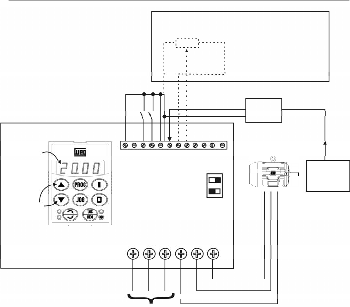
137
CHAPTER 6 - DETAILED PARAMETER DESCRIPTION
Figure 6.28
- Application example of an inverter with PID regulator
CFW-08
P525
Content
Setpoint can
be changed
by the keys
X1
1
2
3
4
5
6
Line
3
4
S1
OFF ON
1
2
3
4
5
6
7
8
9
10
11
12
DI1 - Gen. Enable
DI3 - Manual/Auto
DI4 - Start/Stop
AI1 - Feedback
Pressure
Transducer
4-20 mA
0-25 bar
0-100 %
(0-25 bar)
5k
Setpoint viaAI2 (available
with CFW-08 Plus only)
P222 = 2
P238 = 1.00
P239 = 0
P240 = 0.00
Remote mode operation (P220 = 1).
Setpoint via keypad.
Inverter Parameterization:
P220 = 1
P520 = 1.000
P222 = 0
P521 = 1.000
P234 = 1.00
P522 = 0.000
P235 = 1
P525 = 0
P238 = 0.00
P526 = 0.1s
P203 = 1
P527 = 0
P205 = 6
P528 = 25
Process
138
CHAPTER 6 - DETAILED PARAMETER DESCRIPTION
Range
[Factory Setting]
Parameter
Unit
Description / Notes
P520
0.000 to 7.999
PID Proportional
[ 1.000 ]
Gain
0.001
P521
0.000 to 9.999
PID Integral
[ 1.000
]
Gain
0.001
P522
0.000 to 9.999
PID Differential
[ 0.000
]
Gain
0.001
The integral gain can be defined as being the time
required to change the PI regulator output from 0 to P134,
that is given, in seconds, bythe equation below:
For the following conditions:
-
P040 = P520 = 0.
-
DI3 in automatic position.
P525
0.00 to 100.0
Setpoint (via
[ 0.00
]
Keypad) of the
0.01 %
PID Regulator
Provides the setpoint (reference) of the process via
cointrol via the and keys for the PID regulator,
provided that P221 = 0 (local) or P222 = 0 (remote) has
been set to automatic mode. If it has been set to Manual
Mode, the frequency reference is given by P121.
If P120 = 1 (backup active), the value of P525 is
maintained at the last set value (backup), even when the
inverter is disabled or turned off.
P526
0.01 to 10.00
Process Variable
[ 0.10 s ]
Filter
0.01 s
It sets the time constant of the Process Variable Filter.
It is useful for noise filtering at the analog inputAI1
(feedback of the process variable).
P527
0 or 1
PIDAction
[ 0
]
-
Defines the action type of the PID regulator.
Select it according to the table below:
t =
16
P521
.
P525
P527
0
1
Action Type
Direct
Reverse
For this the
motor speed
must
Increase
Increase
Process
variable
requirement
Increase
Decrease
P527 to be
used
0 (Direct)
1 (Reverse)
Table 6.31
- Configuration of the action type of the PID regulator
Table 6.32
- Description of the options operations for P527

139
CHAPTER 6 - DETAILED PARAMETER DESCRIPTION
P528
0.00 to 99.9
Process Variable
[ 1.00 ]
Scale Factor
0.01 (< 10.0);
0.1 (> 9.99)
Defines the process variable scale. It makes the
conversion between percentage value (used internally by
the inverter) and the process variable unit.
P528 defines how the process variable at P040 will be
shown: P040 = value % x P528.
Set P528 to:
Range
[Factory Setting]
Parameter
Unit
Description / Notes
P528 =
full scale of the used sensor (FM)
P234
P535
0.00 to 100.00
Wake up Band
1.00 %
0.01 %
The parameter P535 influences the “Sleep Mode” only
when the PID regulator is active (P203 = 1).
The “Sleep Mode”, used together with the PID controller,
makes it possible that the inverter be disabled (Srdy)
during intervals when the controlled system is without
load, and that it be enabled immediately when the system
is loaded again.
P535 allows programming the error level at the PID
regulator output, necessary for the inverter to leave the
“Sleep Mode” and to supply the controlled system
requirements again.
Once the PID regulator is active (P203 = 1),the condition
for the inverter to enter the “Sleep Mode” is defined by
P212, and the PID regulator error must be lower than
zero. When this condition is satisfied during the interval
given byP213, the inverterenters the “Sleep Mode”, i.e.:
FE
P212
run
erro
PID
Srdy
t
P213
If the PID action is reverse (P527 = 1) the condition for
the inverter to enter the “Sleep Mode” becomes:
FE
P212
run
erro
PID
0
Srdy
t
P213
If the action of the PID regulator is direct (P527 = 0), the
condition for the CFW-08 to leave the “Sleep Mode” is
defined by P212, and the PID regulator error must be
higher than the P535 value, i.e.:
FE
P212
Srdy
erro
PID
P535
run
t
P213

140
CHAPTER 6 - DETAILED PARAMETER DESCRIPTION
P536
0 or 1
Automatic Setting
[ 0
]
of P525
-
It is possible to enable/disable the copy of P040 (PID
process variable)
in P525 when the changing from ma-
nual to automatic mode using parameter P536, that is
described below.
Range
[Factory Setting]
Parameter
Unit
Description / Notes
P536
0
1
Function
Active (copies the value of P040 in P525)
Inactive (does not copies the value of P040 in P525)
Table 6.33
- Configuration of P536
If the action of the PID regulator is reverse (P527 = 1),
the condition for the CFW-08 to leave the “Sleep Mode”
is defined by P212, and by the PID regulator error must
be lower than the P535 value, therefore:
FE
P212
Srdy
erro
PID
-P535
run
t
P213
Being:
FE
- Frequencyat the ramp input (frequencyreference);
Erro
PID
- The PID setpoint (P525 orAI2) subtracted from
the process variable (P040);
t
- Elapsed time interval;
Srdy
-Active “Sleep Mode” Indication;
run
- Enabled inverter Indication.
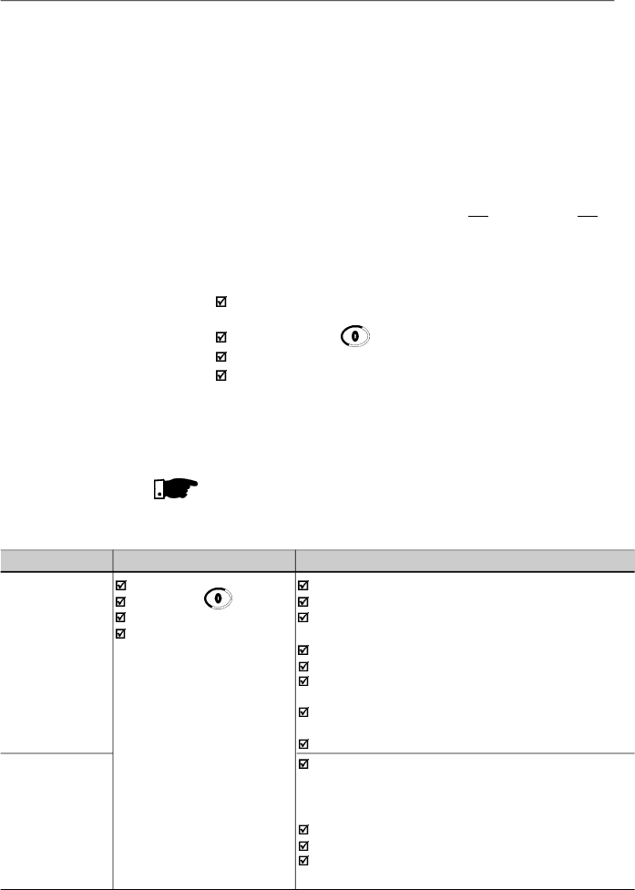
141
DIAGNOSTICSANDTROUBLESHOOTING
This chapter assists the user to identify and correct possible
faults that can occur during the CFW-08 operation. Instructions
about required periodical inspections and cleaning
procedures are also provided.
When a fault is detected, excepting the faults related to the
serial communication,the inverter is disabled and the fault
code is displayed on the readout in E
XX
form, where
XX
is
the actual fault code.
To restart the inverter after a fault has occurred, the inverter
must be reseted. The reset can be made as follows:
Disconnecting and reapplying the AC power (power-on
reset).
By pressing the key (manual reset).
Automatic reset through P206 (auto-reset).
Via digital input: DI3 (P265 = 10), DI4 (P266 = 10),
DI5 (P267 = 10) or DI6 (P268 = 10).
The table 7.1 defines each fault code, explains how to reset
the fault and shows the possible causes for each fault code.
NOTE!
The fault E22, E24, E25, E26, E27 and E28 are related to the
serial communication and are described in item 8.24.5.4.
7.1
FAULTS AND
POSSIBLE CAUSES
FAULT
RESET
(1)
POSSIBLE CAUSES
E00
Power-on
Short-circuit between two motor phases
Output
Manual (key )
Short-circuit to the ground at one or more output phases
overcurrent
Auto-reset
Motor cable capacitance to ground too high, causing peak
(between phases
DI
current at the output (
refer to the
note on next page)
or between phase
Inertia of the load too high, or acceleration ramp too short
and ground)
P169 set too high
Undue set of P136 and/or P137, when in V/F control
(P202 = 0 or 1)
Undue set of P178 and/or P409 when in vector control
(P202 = 2)
IGBT transistor module is short-circuited
E01
Power supply voltage too high, causing a DC link voltage
DC link
higher than the allowed value
overvoltage
Ud > 410 V - 200-240 V models
Ud > 820 V - 380- 480 V models
Load inertia too high or deceleration ramp too short
Setting of P151 too high
Load inertia too high and acceleration ramp too short
(vector control - P202 = 2)
Table 7.1
- Errors, possible causes and reset ways
CHAPTER 7
142
CHAPTER 7 - DIAGNOSTICS AND TROUBLESHOOTING
E02
Power-on
Power supply voltage too low, causing a DC link
DC link
Manual (key )
voltage
lower
than the
minimum
allowed value (read the
undervoltage
Auto-reset
value in parameter P004)
DI
Ud < 200 V - 200 - 240 V models
Ud < 360 V - 380 - 480 V models
E04
Ambient temperature too high (> 40
o
C
[104 ºF]
) and/or
Overtemperature
output current too high
at the power
Blower locked or defective
heatsink or in the
inverter internal air
E05
P156 set too low for the motor that is being used
Motor/inverter
Too much load on motor shaft
overload
Ixt function
E06
Any DI programmed for external fault
External fault
detection is open (not connected to GND - XC1)
E08
Electrical noise
CPU error
(Watchdog)
E09
Contact WEG
Memorywith corrupted values
Program memory
(refer to
item
7.3)
error (Checksum)
E10
Power-on
Defective contact in the HMI-CFW08-RS cable
Keypad copy
Manual (
key
)
Electrical noise in the installation (electromagnetic
function
error
Auto-reset
int
erfer
ence)
DI
E14
Power-on
Motor is not connected to the inverter output
Self-tuning
Manual (
key
)
Wrong motor connection (wrong voltage, lack of one
routine error
Self-tuning routine error
phase)
The used motor is too small for the inverter
(P401 < 0.3 x P295). Use V/Fcontrol
The value of P409 (stator resistance) is too high for the
used inverter
E22
Refer to the item 8.24.5.4
Serial communication error
Serial
communication
error
E24
It is automatically reset
Incompatible parameters were programmed
Programming
when the incompatible
Refer to table 4.1
error
parameters are changed
E25
Refer to the item 8.24.5.4
Serial communication error
Serial
communication
error
E26
Serial
communication
error
Table 7.1 (cont.)
- Errors, possible causes and reset ways
FAULT
RESET
(1)
POSSIBLE CAUSES
143
CHAPTER 7 - DIAGNOSTICS AND TROUBLESHOOTING
FAULT
RESET
(1)
POSSIBLE CAUSES
E27
Refer to the item 8.24.5.4
Serial communication error
Serial
communication
error
E28
Refer to the item 8.24.5.4
Serial communication error
Serial interface
Watchdog
timeout error
E31
It is reset automatically
Keypad cable misconnected
Keypad
when the communication
Electrical noise in the installation (electromagnetic
(HMI-CFW08-RS)
between inverter and the
interference)
connection fault
keypad is reestablished
E32
Power-on
Motor is under an overload condition
Motor
Manual
Reset
(
key
)
Duty cycle is too high (too many starts/stops per
overtemperature
Auto-reset
minute)
DIx
Ambient temperature is too high
Bad contact or short-circuit (resistance < 100
)
on wiring at terminals XC1:6 and 7 or XC1:7 and 8 of
the control board (wiring that comes from the
motor thermistor - PTC)
E41
Contact WEG
Inverter power circuit is defective
Self- diagnosis
(refer to item 7.3)
fault
NOTE!
Long motor cables (longer than 50 m (150 ft)) can generate
excessive capacitance to ground. This can cause nuisance
ground fault trip and consequently disabling by E00 fault
immediately after the inverter has been enabled.
Solution:
Reduce the switching frequency(P297).
Connect a load reactor in series with the motor supplyline.
Refer to item 8.22.
NOTE!
The faults act as follows:
E00 to E06: switches off the relay that has been
programmed to “no fault”, disables the PWM pulses,
displays the fault code on the display and the “ERROR”
LED flashes. Some data are saved on the
EEPROM
memory
:
keypad
refer
ence and EP (electronic
potentiometer) (when the function “backup of the
(1)
In case of E04 Fault due to inverter overtemperature, allow
the inverter to cool down before trying to reset it.
In the types 7.3 A and 10 A/200-240 V and 6.5 A, 10 A,
13 A, 16 A, 24 A and 30 A/380-480 V fitted with internal
Category C2
RFI-filters, the fault E04 can be caused by
internal airflow overtemperature. Please check blower
installed inside.
Table 7.1
(cont.)
- Errors, possible causes and reset ways
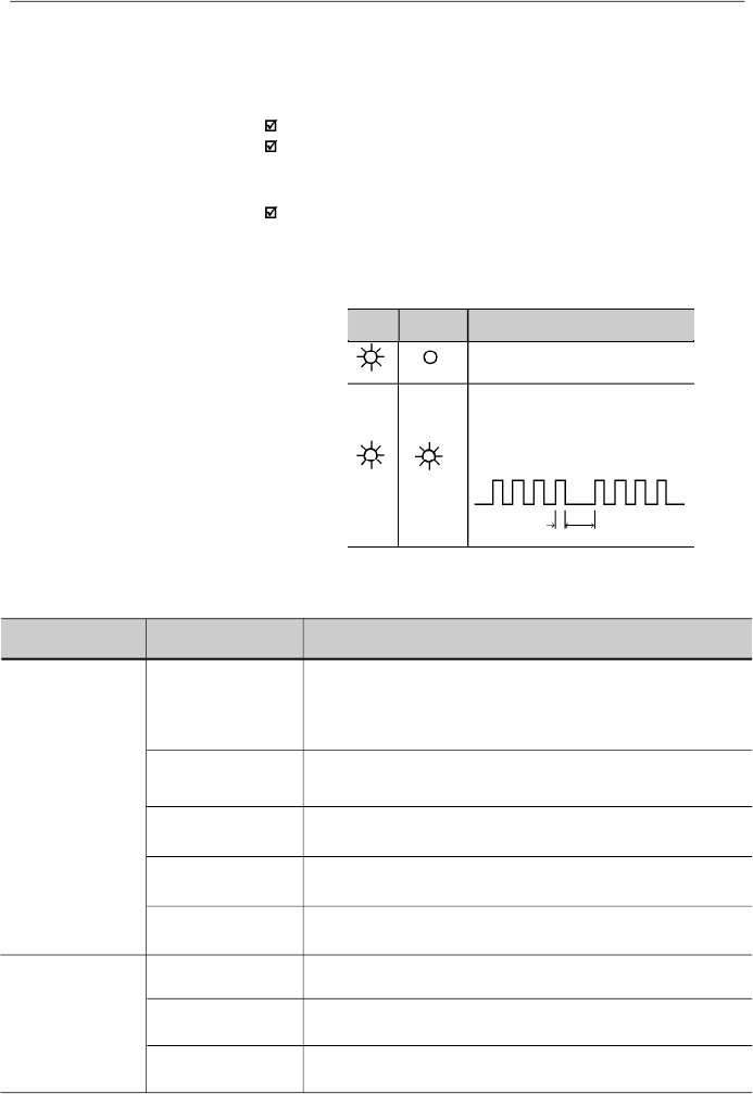
144
CHAPTER 7 - DIAGNOSTICS AND TROUBLESHOOTING
(Flashing)
Inverter is powered up and is ready
A fault has been detected
The Error LED flashes, indicating
the number of the fault code
Example: E04
0.2 s
0.6 s
Power
LED
Error LED
Description
7.2
TROUBLESHOOTING
Table 7.2
- Meaning of LEDs indication for drive status
Off
On
On
references
”
at
P120
has been enabled
),
the occurred fault
number
,
the status of the integrator of the IxT function
(overcurrent).
E24: indicates the fault code on the LED display.
E31: inverter proceeds to operate normally, but it does not
accept the keypad commands; the fault code is indicated
on the LED display.
E41: does not allow inverter operation (it is not possible to
enable the inverter); the fault code is indicated on the LED
display and on the “ERROR” LED.
Indication on the Inverter Status LEDs:
PROBLEM
POINT TO BE
CORRECTIVE ACTION
CHECKED
Motor does not run
Incorrect wiring
1.Check the power and the control connections. For example,
the digital inputs DIx programmed for Start/Stop or General Enable
or No External Fault must be connected to GND (pin 5 of the
control connector XC1)
Analog reference
1.Check if the external signal is properly connected
(if used)
2.Check the status of the speed potentiometer (if used)
Incorrect Programming
1.Check if the parameters are properly programmed for the
application
Fault
1.
Check if the inverter has not been disabled due to detected fault
condition (refer to
item 7.1
)
Motor Stall
1.
Reduce the motor load
2.
Increase P169 or P136/P137
Motor speed varies
Loose connections
1.Disable the inverter, switch OFF the power supply and tighten all
(oscillates)
connections
Defective speed
1.Replacethe defective speed potentiometer
potentiometer
V
aria
tion of the external
1.Identify the cause of the variation
analog reference
Table 7.3
- Solution for the most frequent problems
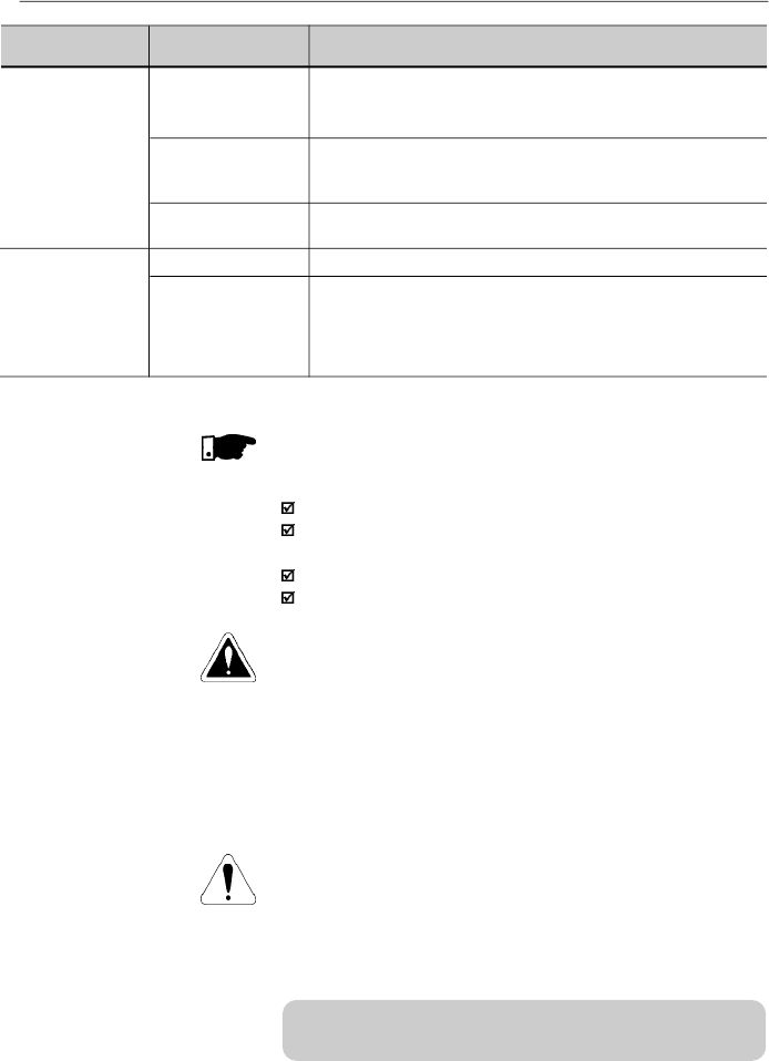
145
CHAPTER 7 - DIAGNOSTICS AND TROUBLESHOOTING
NOTE!
Whencontacting WEG for services, please have the following
data on hand:
Invertermodel.
Serial number
,
manufacturing date and
hardware
revision,
as indicated in the inverter nameplate (refer to item 2.4).
Software version (refer to item 2.2).
Information about the application and inverter programming.
7.3
CONTACTING
WEG
7.4
PREVENTIVE
MAINTENANCE
DANGER!
Always disconnect the power supply voltage before touching
anycomponent of the inverter.
Even after switching OFF the inverter, high voltages may be
present. Wait 10 minutes to allow complete discharge of the
power capacitors.
Always connect the equipment frame to a suitable ground (PE)
point.
ATTENTION!
Electronic boards have components sensitive to electrostatic
discharges.
Never touch the components or connectors directly. If this is
unavoidable, first touch the metallic frame or use a suitable
ground strap.
Never apply a high voltage test on the inverter!
If this is necessary, contact WEG.
To avoid operation problems caused by harsh ambient
conditions, such as high temperature,moisture, dirt, vibration
or premature ageing of the components, periodic inspections
of the inverter and installations are recommended.
PROBLEM
POINT TO BE
CORRECTIVE ACTION
CHECKED
Motor speed too
Programming error
1.Check if the contents of P133 (minimum frequency) and P134
high or too low
(reference limits)
(maximum frequency) are according to the motor
and to the
application.
Signal of the
1.Check the
level of the
control signal of the reference.
Reference Control
2.Check the programming (gains and offset) at P234 to P240.
(if used)
Motor nameplate
1.Check if the used motor meets the application requirements.
data
Display OFF
Keypad connection
1.Check the keypad connections to the inverter.
Power supply
1.The power supply must be within the following ranges:
200-240 V models:
- Min: 170 V
- Max: 264 V
380-480 V models:
- Min: 323 V
- Max: 528 V
Table 7.3 (cont.)
- Solution for the most frequent problems
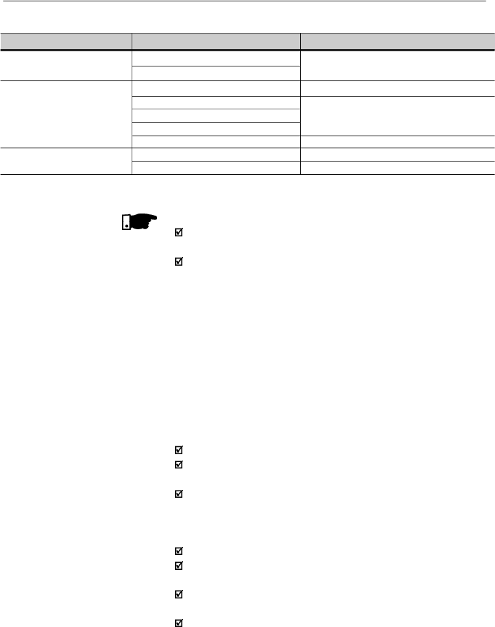
146
CHAPTER 7 - DIAGNOSTICS AND TROUBLESHOOTING
7.4.1
Cleaning Instructions
When required to clean the inverter, follow the instructions
below:
a) Cooling System:
RemoveAC power from the inverter and wait 10 minutes.
Remove all dust from ventilation openings by using a plastic
brush or a soft cloth.
Remove dust accumulated on the heatsink fins and from
the blower blades with compressed air.
b) Electronic Boards:
RemoveAC power from the inverter and wait 10 minutes.
Disconnect the inverter cables, ensuring that they are
marked carefullyto facilitate later reconnection.
Remove the keypad and the plastic cover (refer to chapter
3).
Remove all dust from the printed circuit boards by using an
anti-static soft brush and/or remove it with an ionized
compressed air gun, (for example: Charges Burtes Ion Gun
(non nuclear) Ref.A6030-6 DESCO).
COMPONENTS
PROBLEMS
CORRECTIVEACTIONS
Terminal blocks
Loose screws
Tighten them
Loose connectors
Blowers / Cooling
Blowers are dirty
Clean them
system
Abnormal acoustic noise
Replace the blowers
Blower is not running
Abnormal vibration
Dust in the air filters
Clean or replace them
Printed circuit boards
Dust, oil or moisture accumulation
Clean them and/or replace them
Smell
Replace them
Table 7.4
- Periodic inspection after start-up
NOTE!
It is recommended to replace the blowers after 40,000 hours
of operation.
When the drive is stored for a long time, it is recommended
to power the drive up and keep it running for 1 hour every
year. Make sure to use a power supply with the following
characteristics for all models (200-240V or 380-480V):
220V, single-phase or three-phase, 50 Hz or 60 Hz (for
three-phase power supply),without connecting the motor to
the drive output.After powering up the drive, keep it off for
24 hours before using it again.

147
CHAPTER 8
CFW-08 OPTIONSANDACCESSORIES
This chapter describes the optional devices that can be used
internal or external with the CFW-08. Table below shows a list
of existing optional devices and the types to which they are
applied. In the other items also are given information about
the optional devices and their application.
Name
HMI-CFW08-P
TCL-CFW08
HMI-CFW08-RP
MIP-CFW08-RP
HMI-CFW08-RS
MIS-CFW08-RS
CAB-RS-1
CAB-RS-2
CAB-RS-3
CAB-RS-5
CAB-RS-7.5
CAB-RS-10
CAB-RP-1
CAB-RP-2
CAB-RP-3
CAB-RP-5
CAB-RP-7.5
CAB-RP-10
KCS-CFW08
KSD-CFW08
KRS-485-
CFW08
KFB-CO-CFW08
KFB-DN-CFW08
KAC-120-
CFW08
KAC-120-
CFW08 N1M1
KDC-24VR-
CFW08
Function
Parallel keypad (HMI)
Cover to be inserted in the place of the parallel HMI (when it is
mounted in the inverter or it is remote - kit KMR-CFW08-P)
HMI parallel keypad. For remote use with MIP-CFW08-RP
interface and CAB-CFW08-RP cable (up to 10 m [32.8 ft])
Interface for the external parallel keypad (remote) HMI-CFW08-RP
HMI serial keypad. For remote use with MIS-CFW08-RS
interface and CAB-RS cable (up to 10 m [32.8 ft]). CopyFunction
Interface for the external serial keypad (remote) HMI-CFW08-RS
Cable for the remote serial keypad - cable: 1 m (3.28 ft)
Cable for the remote serial keypad - cable: 2 m (6.56 ft)
Cable for the remote serial keypad - cable: 3 m (9.84 ft)
Cable for the remote serial keypad - cable: 5 m (16.4 ft)
Cable for the remote serial keypad - cable: 7.5 m (24.6 ft)
Cable for the remote serial keypad - cable: 10 m (32.8 ft)
Cable for the remote parallel keypad - cable: 1 m (3.28 ft)
Cable for the remote parallel keypad - cable: 2 m (6.56 ft)
Cable for the remote parallel keypad - cable: 3 m (9.84 ft)
Cable for the remote parallel keypad - cable: 5 m (16.4 ft)
Cable for the remote parallel keypad - cable: 7.5 m (24.6 ft)
Cable for the remote parallel keypad - cable: 10 m (32.8 ft)
RS-232 serial communication interface (PC, PLC, etc)
RS-232 PC Communication kit: interface RS-232 (KCS-CFW08),
cable RJ-11 to DB9, 3 m (9.84 ft) long, software “SUPERDRIVE”
RS-485 serial communication interface and keypad
CANopen communication interface and keypad
DeviceNet communication interface and keypad
Interface for 120 Vac digital inputs
Interface for 120 Vac digital inputs + Kit Nema 1
24 Vdc power supply with an interface for the CFW-08 remote
parallel HMI connection
Models to which
are applied
All
All, however the
versionA3 of the
control board is
needed
(refer to item 2.4)
All, however the
versionA4 of the
control board is
needed
(refer to item 2.4)
22-28-33A/
200-240 V and
13-16-24-30 A/
380-480 V
1.6-2.6-4.0-7.0A/
200-240 V and
1.0-1.6-2.6-4.0A/
380-480 V
All
WEG item
number
417118200
417118211
417118217
417118216
417118218
417118219
0307.7827
0307.7828
0307.7829
0307.8113
0307.8114
0307.8115
0307.7711
0307.7712
0307.7713
0307.7833
0307.7834
0307.7835
417118212
417118207
417118213
417118221
417118222
417118223
417118224
10941082
Table 8.1
- Available optional devices for the CFW-08

148
CHAPTER 8 - CFW-08 OPTIONS AND ACCESSORIES
Name
KDC-24V-CFW08
KAC-120-CFW08 -
N1M2
KMD-CFW08-M1
KFIX-CFW08-M1
KFIX-CFW08-M2
KN1-CFW08-M1
KN1-CFW08-M2
FIL1
FIL2
FIL4
FEX1-CFW08
FEX2-CFW08
FS6007-16-06
FN3258-7-45
FS6007-25-08
FS6007-36-08
FN3258-16-45
FN3258-30-47
FN3258-55-52
TOR1-CFW08
TOR2-CFW08
Function
24 Vdc power supply with the CFW-08 HMI
Interface for 120 Vac digital inputs + Kit Nema 1
Rail Kit DIN EN 50.022
Fix Kit -M1
Fix Kit - M2
Kit Nema 1/IP20 for the connection of the metallic
conduit -M1
Kit Nema 1/IP20 for the connection of the metallic
conduit -M2
Internal Category C2 suppressor filter RFI - A - 7.3-10 A/
200-240 V
Internal Category C2 suppressor filter RFI- A - 2.7-4.3-
6.5-10 A/380-480 V
InternalCategoryC2suppressorfilter- RFI-13-16A/380-480V
10 A/200-240 V Category C2 RFI filter - footprint
5 A/380-480 V Category C2 RFI filter - footprint
External Category C1 suppressor filter - RFI -
1.6-2.6-4.0A/200-240 V
External Category C1 suppressor filter - RFI -
1.0-1.6-2.6-2.7-4.0-4.3A/380-480 V
External Category C1 suppressor filter - RFI - 7.3 A/
200-240 V single-phase
External Category C1 suppressor filter - RFI - 10A/200-240 V
single-phase
External Category C1 suppressor filter - RFI - 6.5-10-13A/
380-480 V
External Category C1 suppressor filter - RFI 16 A, 24 A/
380-480 V
External suppressor filter - RFI Category C2 - 30 A/
380-480 V
CMchoketoroid #1 (Thornton NT35/22/22-4100-IP12R) and
plastic clamp
CM choke toroid #2 (Thornton NT52/32/20-4400-IP12E)
Models to which
are applied
All
7.3-10-16A/
200-240 V and
2.7-4.3-6.5-10A/
380-480 V
1.6-2.6-4.0-7.0A/
200-240 V
1.0-1.6-2.6-4.0A/
380-480 V
1.6-2.6-4.0-7.0A/
200-240 V
1.0-1.6-2.6-4.0A/
380-480 V
7.3-10-16A/
200-240 V
2.7-4.3-6.5-10A/
380-480 V
1.6-2.6-4.0-7.0A/
200-240 V
1.0-1.6-2.6-4.0A/
380-480 V
7.3-10-16A/
200-240 V
2.7-4.3-6.5-10A/
380-480 V
7.3-10 A/
200-240 V
2.7-4.3-6.5-10A/
380-480 V
13-16A/380-480V
1.6-2.6-4.0 A/
200-240 V
1.0-1.6-2.6-4.0A/
380-480 V
1.6-2.6-4.0 A/
200-240 V
1.0-1.6-2.6-2.7-4.0-
4.3A/380-480V
7.3 A/200-240 V
10A/200-240 V
6.5-10-13A/
380-480 V;
7A/200-240 V;
7.3-10A/200-240V
three-phase
16
-24
A/380-480
V;
16-22A/200-240V
30 A/380-480 V;
28-33A/200-240 V
2.7-4.3-6.5-10A/
380-480 V
2.7-4.3-6.5-10-13-
16A/380-480 V
WEG item
number
10941080
417118225
417100879
417100994
417100995
417118209
417118210
4151.2661
4151.0994
4151.2148
417118238
417118239
0208.2072
0208.2075
0208.2073
0208.2074
0208.2076
0208.2077
0208.2078
417100895
417100896
Table 8.1 (cont.) -
Available optional devices for the CFW-08
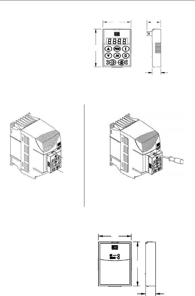
149
CHAPTER 8 - CFW-08 OPTIONS AND ACCESSORIES
8.1
HMI-CFW08-P
Parallel keypad (HMI):
is the keypad that is mounted at the
front side of the inverter.
Figure 8.1
- Dimensions in mm [in] of the parallel HMI - HMI-CFW08-P
57
[2.24]
43
[1.69]
21
[0.83]
13
[0.51]
Figure 8.2 a) and b)
- Instructions for HMI-CFW08-P insertion and removing
8.2
TCL-CFW08
Dummy panel to be inserted in the place of the parallel keypad
(HMI-CFW08-P).
Figure 8.3
- Dimensions in mm [in] of the dummy panel TCL-CFW08
for the parallel HMI
8.1.1
Instruction for Insertion and Removing of the HMI-CFW08-P
1. Unlock the keypad byusing a screwdriver as
shown above.
2. Remove the keypad bypulling on the lateral
sides.
1. Place the keypad as shown above.
2. Press it.
b)Removing
a) Insertion
57
[2.24]
43
[1.69]
13
[0.51]
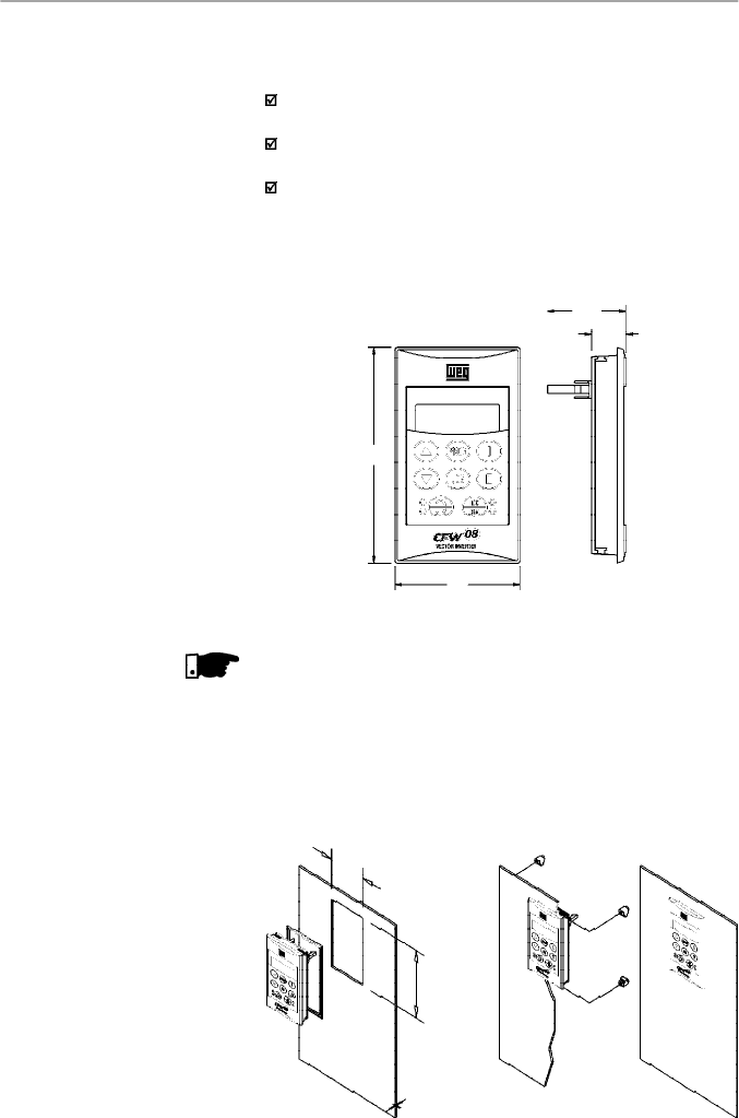
150
CHAPTER 8 - CFW-08 OPTIONS AND ACCESSORIES
8.3
HMI-CFW08-RP
External parallel keypad:
this keypad is mounted externally
to the inverters with Nema 12/IP54 degree of protection and
can be used in the following cases:
Applications that require a remote keypad (up to 10 m /
32.8 ft).
For the HMI installation at a panel door (0.12 in) or command
console.
For a better visualization on the displayand to facilitatethe
keypad operation, when compared with the parallel keypad
(HMI-CFW08-P).
The external parallel keypad (HMI-CFW08-RP) must be used
with the MIP-CFW08-RP interface and CAB-RP-X cable.
Figure 8.4 -
Dimensions in mm [in] of the HMI-CFW08-RP
8.3.1
HMI-CFW08-RP
Installation
The HMI-CFW08-RPcan be installed directly on the panel door
(0.12 in), as shown in the figures below:
Figure 8.5 -
Installation of the HMI-CFW08-RP
58
[2.28]
98
[3.86]
15.9
[0.63]
36.3
[1.43]
NOTE!
This optional is not compatible with the version “A3” and “A4”
of the control board. Refer to item 2.4 for further information
on these control boards.
52 mm
(2.05 in)
92 mm
(3.62 in)
Max.3mm
(0.12in)
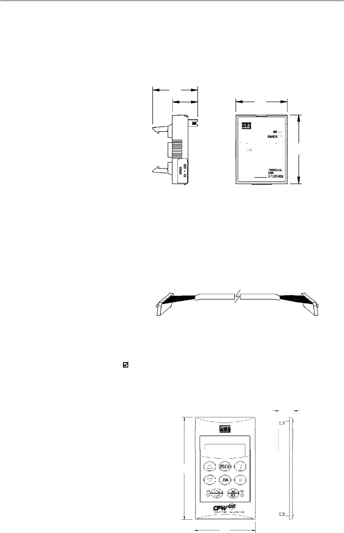
151
CHAPTER 8 - CFW-08 OPTIONS AND ACCESSORIES
8.5
CAB-RP-1
CAB-RP-2
CAB-RP-3
CAB-RP-5
CAB-RP-7.5
CAB-RP-10
Cables used to connect the inverter to the external parallel
interface keypad (HMI-CFW08-RP).
There are 6 cables options ranging in lenghts from 1 m (3.28 ft)
to 10 m (32.8 ft). The user must select among these lenghts
according to the requirement.
The cable CAB-RP must be laid separately from the power
wiring by meeting the requirements for the control wiring (refer
to item 3.2.5).
Figure 8.7 -
CAB-RP-X
8.6
HMI-CFW08-RS
Figure 8.6
- Dimensions in mm [in] of the MIP-CFW08-RP
Lateral View
Front View
Figure 8.8
- Dimensions in mm [in] of the HMI-CFW08-RS
External serial keypad:
this interface is mounted external
to the inverters with Nema 12/IP54 degree of protection and
must be used when the copy function is needed:
For more details aboutcopy function refer to the description
of the parameter P215 in chapter 6.
It operates with the MIS-CFW08-RS and the cable CAB-RS-X
,
which length must be chosen according to the needs (up to
10 m (32.8 ft)).
8.4
MIP-CFW08-RP
Interface for the external parallel keypad HMI-CFW08-RP,
installed in the inverter instead of the standard keypad only
when the remote parallel keypad (HMI-CFW08-RP) is used.
TheproceduresforinsertionandremovingoftheMIP-CFW08-RP
are similar to those shown in figure 8.16 for the KCS-CFW08
module.
37
[1.46]
21
[0.83]
43
[1.69]
57
[
2.24]
15.9
[0.63]
58
2.28
98
[3.86]
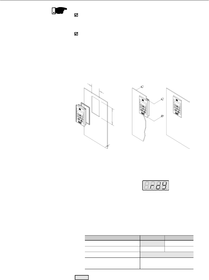
152
CHAPTER 8 - CFW-08 OPTIONS AND ACCESSORIES
8.6.2
HMI-CFW08-RS
Start-up
After installation (including interconnecting cable), power-up
the inverter.
HMI-CFW08-RS must display
The inverter programming via HMI-CFW08-RS is exactly the
same as the inverter programming via HMI-CFW08-P (for
more details about the programming, refer to chapter 4).
To enable all the keys of the HMI-CFW08-RS and thus
make
it equivalent to HMI-CFW08-P both for programming
and operation, set the following parameters:
8.6.1
HMI-CFW08-RS
Installation
The remote serial keypad (HMI-CFW08-RS) can be installed
in the cabinet door(door thickness between 1 and 3 mm [0.04
and 0.12 in]), as presented in the following figures.
Figure 8.9
- Installation of the HMI-CFW08-RS
Function via HMI-CFW08-RS
Frequency reference
Commands
(*)
Forward/Reverse Selection
Local/Remote Selection
Local Mode
P221 = 0
P229 = 2
Remote Mode
P222 = 0
P230 = 2
P231 = 2
P220 = 5 (default local) or
P220 = 6 (default remote)
Note:
Factory Setting
(*)
Except the forward/reverse selection that also depends on the parameter
P231.
Table 8.2
- Parameter setting for HMI-CFW08-RS operation
NOTE!
Due to the internal processing time of CFW-08 it is not
possible to use the external serial keypad, with the switching
frequency set to 15 kHz (P297 = 7).
This optional is not compatible with the version “A3” and
“A4” of the control board. Refer to item 2.4 for further
information on these control boards.
52 mm
(2.05 in)
92 mm
(3.62 in)
Max. 3 mm
(0.12 in)
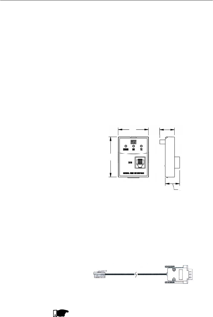
153
CHAPTER 8 - CFW-08 OPTIONS AND ACCESSORIES
8.7
MIS-CFW08-RS
Serial i
nterface
used exclusively for
HMI-CFW08-RS
keypad
connection to inverter.
The procedures for insertion and removing of the MIS-
CFW08-RS are similar to those shown in
f
igure 8.1
6
for the
KCS-CFW08 module.
Figure 8.10
- Dimensions in mm [in] of the MIS-CFW08-RS serial
communication module for the external serial HMI
Cables used to connect the inverter to the external serial
interface keypad (HMI-CFW08-RS). There are 6 cable options
ranging in lengths from 1 m to 10 m(3.28 ftto 32.8 ft). The user
mustselect among these lengths according to the requirement.
The cable CAB-RS must be laid separately from the power
wiring by meeting the requirements for the control wiring (refer
to item 3.2.5).
8.8
CAB-RS-1
CAB-RS-2
CAB-RS-3
CAB-RS-5
CAB-RS-7.5
CAB-RS-10
NOTE!
Cables with 5 m (16.4 ft) and longer ones (5 m (16.4 ft), 7.5 m
(24.6 ft) and 10 m (32.8 ft)) are shielded, and their shield must
be connected to the ground.
Figure 8.11
- CAB-RS-X
Inverter
RJ Connector
Keypad
DB9
Connector
8.6.3
Keypad Copy Function
The HMI-CFW08-RS keypad still has an additional function:
thekeypad copyfunction.This function isuseful whenone wants
to copythe settings of one inverter (source inverter) to another
(target inverter) or one needs to program several inverters
with the same settings.
Thisis done as follows: the parameters of the source inverter
are copied to a non-volatile memory of the HMI-CFW08-RS
keypad , and then from this keypad to another inverter (“target
inverter"). The keypad copy function is controlled by the
parameter P215.
For further information onthis function refer to parameter P215
in the chapter 6.
57
[2.24]
43
[1.69]
21
[0.83]
20
[0.79]
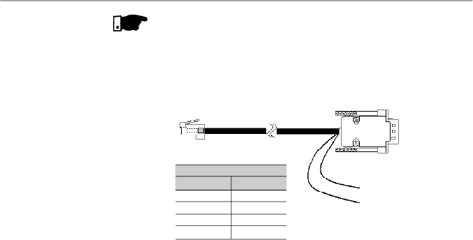
154
CHAPTER 8 - CFW-08 OPTIONS AND ACCESSORIES
8.9
KDC-24VR-CFW08
24 Vdc power supplywith HMI for the CFW-08:
This optional module makes it available a 24 Vdc power supply
with 75 mA maximum current capacity and short-circuit
protection. The power supply reference (0 V – GND) is the
same of the terminal 5 on the control board.
The module also makes available an interface for the remote
parallel HMI connection, in order to set the CFW-08 frequency
inverter from a panel door.
This optional module is inserted at the front cover of the inverter
in the place of the standard HMI (HMI-CFW08-P). For further
details on the installation of this optional module, refer to the
section regarding the installation of the KCS-CFW08 option
in this manual. The 24 Vdc power supplypolarity is indicated
above the terminals, according to the figure 8.13.
Figure 8.12 -
CAB-RS-X
Inverter
RJ11 6X6 Connector
Keypad
DB9 Connector
PIN 1 = +12 Vdc (250 mA)
PIN 5 = 0 V
Pins DB9
1
2
3
5
Pins RJ
1
6
4
5
Cable Connection
Note:
WEG supplies cables with this configuration for 15 m (49.2 ft),
20 m (65.6 ft) and 25 m (82 ft). Longer cables are not supplied by WEG.
NOTE!
The external serial keypad (HMI-CFW08-RS)can be used up
to 150 m (492.1 ft), for distance higher than 10 m (32.8 ft) it is
necessary to use a 12 Vdc external power supply in the
external serial keypad, as shown in the figure below:
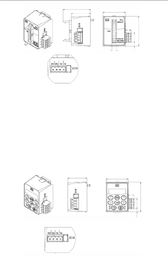
155
CHAPTER 8 - CFW-08 OPTIONS AND ACCESSORIES
8.10
KDC-24V
-CFW08
24 Vdc power supplywith HMI for the CFW-08:
This module makes it available a 24 Vdc power supply with
100 mA maximum current capacity and short-circuit protection.
The power supply reference (0 V - GND) is the same of the
terminal 5 on the control board.
The module also makes available a standard HMI in order to
set the CFW-08 frequency inverter.
This optional module is inserted at the front cover of the inverter
in the place of the standard HMI (HMI-CFW08-P). For further
details on the installation of this optional module, refer to the
section regarding the installation of the KCS-CFW08 option
in this manual.
The 24 Vdc power supply polarity is indicated above the
terminals, according to the figure 8.14.
Figure 8.14
- Dimensions in mm [in] of the optional module KDC-24V-CFW08 and XC16 connector signals
Figure 8.13
- Dimensions in mm [in] of the optional module KDC-24VR-CFW08 and XC16 connector signals
36,8[1.45]
42,6[1.68]
11[0.43]
57 [2.24]
20[0.79]
5,9[0.23]
36,8[1.45]
43,2 [1.7]
53,1[2.09]
10,9[0.43]
9[0.35]
57,6[2.27]
20[0.79]
6,1[0.24]
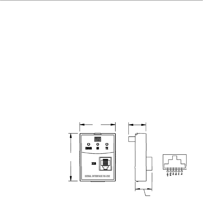
156
CHAPTER 8 - CFW-08 OPTIONS AND ACCESSORIES
8.11
KCS-CFW08
Serial communication module RS-232: is inserted in the place
of the parallel keypad, enabling the RS-232 connection
(connector RJ-6).
The RS-232 serial interface enables the point-to-point
connection (inverter - master). It is gavanically isolated and
enables the use of interconnecting cables in lengths up to 10 m
(32.8 ft)
.
Through the RS-232 serial interface you can control, set
parameters and monitor the CFW-08. The communication
protocol is based onthe communication byenquiry/response
(master/slave), according to ISO1745, ISO 646, with character
exchange of type ASCII between the inverter (slave) and the
master. The Master can be a PLC, a PC, etc. The maximum
transfer rate is 38400 bps.
For the RS-485 serial communication, both point-to-point (an
inverter and a master) or multipoint (up to 30 inverters and
one master), you can connect the KCS-CFW08 module to an
KRS-485-CFW08 module - for more details, refer to item 8.13.
43
[1.69]
21
[0.83]
57
[2.24]
Figure 8.15
- Dimensions in mm [in] of the RS-232 serial
communication module KCS-CFW08 and RJ (XC8) signal connector
20
[0.79]
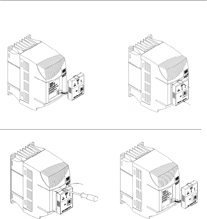
157
CHAPTER 8 - CFW-08 OPTIONS AND ACCESSORIES
Figure 8.16 a) and b)
- Insertion and removal of the serial communication module RS-232 KCS-CFW08
8.12
KSD-CFW08
The complete kit, that enables the connection of the CFW-08
to a PC via RS-232 contains:
-
Serial communication module RS-232 (KCS-CFW08);
-
3 m (9.8 ft) cable RJ-11 for the DB9;
-
Software SuperDrive that enables the CFW-08
programming, operating and monitoring. Refer to the
SuperDrive manual for hardware and system configurations.
8.11.1
Instructions for
KCS-CFW08
Insertion and Removal
- Connect the cable of the
communication module to XC5.
-
Place the communication module as
shown in figure above.
- Press it.
a) Insertion
- Use a screwdriver to unlock the communication module.
- Remove the module by pulling it on the lateral sides.
b)Removing
- Remove the cable of the XC5 connector.
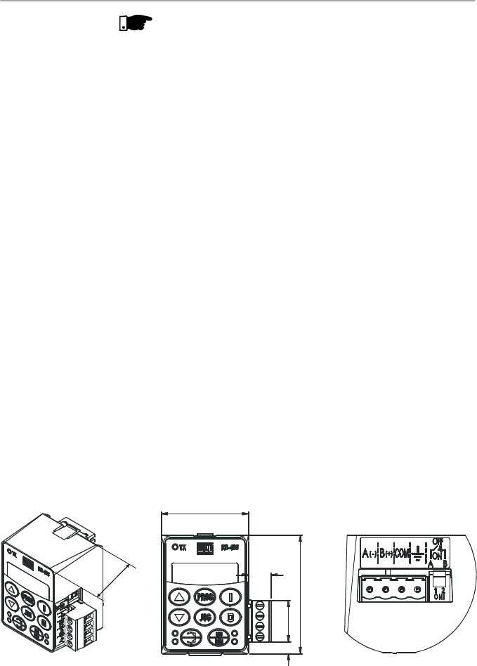
158
CHAPTER 8 - CFW-08 OPTIONS AND ACCESSORIES
To install the RS-232 communication kit on the PC, proceed
as follows:
-
Remove the parallel keypad (HMI-CFW08-P) from the
inverter.
-
Install the serial communication module RS-232 (KCS-
CFW08) in the place of the keypad.
-
Install the software “SuperDrive” in the PC.
-
Connect the inverter to the PC through the cable.
-
Followthe instruction given bythe “SuperDrive”.
RS-485 Serial Communication Module and Keypad:
This optional module, with an RS-485 connection (plug-in
connector) and a keypad,is installed in the front of the inverter
in the place of the standard parallel keypad (HMI-CFW08-P).
For instruction on how inserting and removing this module,
refer to the installation instruction for the KCS-CFW08 in this
manual.
The functions of each pin are indicated in the silk screening
above the communication connector.
The RS-485 interface allows a multi-point connection of up to
1000 m (3280.8 ft) usingthe Modbus-RTU or WEG protocols.
These protocols are described in the item “Serial
Communication” of this manual.
It is possible to command, setup and monitor the CFW-08
through the RS-485 serial interface. In this case, the master
can be a PLC, a PC, etc.
8.13
KRS-485-CFW08
Figure 8.17
- Dimensions in mm [in] of the RS-485 serial communication module
KRS-485-CFW08
42.6
[1.68]
11
[0.43]
5.6
[0.22]
57
[2.24]
20
[0.79]
36.8
[1.45]
NOTE!
For communication with the CFW-08 use the first generation
programming software SuperDrive. The second generation
software named SuperDrive G2 is not compatible with this
product.
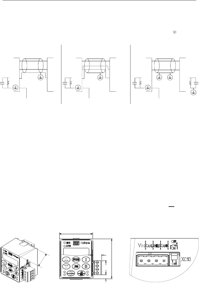
159
CHAPTER 8 - CFW-08 OPTIONS AND ACCESSORIES
The following figure shows some possibilities for connecting
this module in a RS-485 network. Usually,the connection a) is
applied, but connections b)and c) can also be used according
to the situation.
Notice that terminal indicated by the symbol
shall be
connected to the ground.
Figure 8.18 a) to c)
- Connection possibilities for the KRS-485-CFW08 module
CANopen Communication Module and Keypad:
This optional module, with a CANopen interface (plug-in
connector) and a keypad, is installed in the frontof the drive in
the place of the standard parallel keypad (HMI-CFW08-P).
For instruction on how inserting and removing this module,
refer to the installation instruction for the KCS-CFW08 in this
manual.
The functions of each pin are indicated in the silk screening
above the communication connector.
It is possible to command, setup and monitor the CFW-08
through this communication interface. In this case, the master
can be a PLC, the CFW-09 with a PLC board, etc.
This module can be purchased along with the inverter just by
including the code “A3” in the control board field of the product
part number, such as, CFW080040S2024PO
A3
Z (refer to
item 2.4 of this manual for further information on howordering
the product).
8.14
KFB-CO-CFW08
Figure 8.19
-
Dimensions in mm [in] of the CANopen communication module
KFB-CO-CFW08
a)
b)
c)
36.8
[1.45]
CFW-08
Master
A
B
A
B
A
B
A
B
CFW-08
Master
COM
COM
COM
COM
XC12
XC12
Earth
Earth
CFW-08
Master
A
B
A
B
COM
XC12
Earth
COM
42.6
[1.68]
11
[0.43]
57
[2.24]
20
[0.79]
5.9
[0.23]
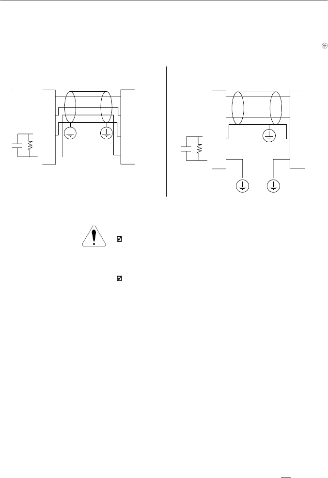
160
CHAPTER 8 - CFW-08 OPTIONS AND ACCESSORIES
The following figure shows some possibilities for connecting
the module in a CANopen network. Usually, the connection a)
is applied, but connection b) can also be used according to
the situation. Notice that terminal indicated by the symbol
shall be connected to the ground.
Figure 8.20 a) and b) -
Connection possibilities for the KFB-CO-CFW08 module
ATTENTION!
This module can onlybe used with the drives that have the
“A3” initials in the nameplate (refer to item 2.4 of this ma-
nual). Otherwise, the CANopen communication as well as
the keypad will not work.
It is notpossible to use the parallel keypad, the serial remote
keypad, the parallel remote keypad,and the serial protocols
(such as Modbus and WEG) with version “A3”of the control
board.
DeviceNet Communication Module and Keypad:
This optional module, with a DeviceNet interface (plug-in
connector) and a keypad, isinstalled in the front of the inverter
in the place of the standard parallel keypad (HMI-CFW08-P).
For instruction on how inserting and removing this module,
refer to the installation instruction for the KCS-CFW08 in this
manual.
The functions of each pin are indicated in the silk screening
above the communication connector.
It is possible to command, setup and monitor the CFW-08
through this communication interface. In this case, the master
can be a PLC or other device that supports this communication
protocol.
This module can be purchased along with the inverter just by
including the code “A4”in the control board field of the product
part number, such as, CFW080040S2024PO
A4
Z (refer to
item 2.4 of this manual for furtherinformationon howordering
the product).
8.15
KFB-DN-CFW08
CFW-08
CAN_H
CAN_L
CAN_H
CAN_L
Shield
Shield
V-
V-
XC13
Master
CFW-08
CAN_H
CAN_L
CAN_H
CAN_L
Shield
Shield
V-
V-
XC13
Master
b)
a)
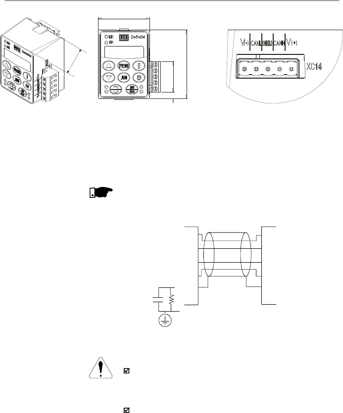
161
CHAPTER 8 - CFW-08 OPTIONS AND ACCESSORIES
Figure 8.21 -
Dimensions in mm [in] of the DeviceNet communication module
KFB-DN-CFW08
The figure below shows how to connect this module in a
DeviceNet network (this connection follows the DeviceNet
resolution).
NOTE!
Terminal 5 (GND) of the control board shall be grounded.
Figure 8.22
-
Connection possibilities for the KFB-DN-CFW08 module
ATTENTION!
This module can onlybe used with the drives that have the
“A4” initials in the intelligent code (refer to item 2.4 of this
manual). Otherwise, theDeviceNet communication as well
as the keypad will not work.
Itis not possible to use the parallel keypad, the serial remote
keypad, the parallel remote keypad and the serial protocols
(such as Modbus and WEG) with version “A4” of the control
board.
42.6
[1.68]
5.6
[0.22]
57
[2.24]
25.3
[1.0]
36.8
[1.45]
CFW-08
Master
V+
V+
CAN_H
CAN_L
V-
CAN_H
CAN_L
V-
Shield
Shield
XC14
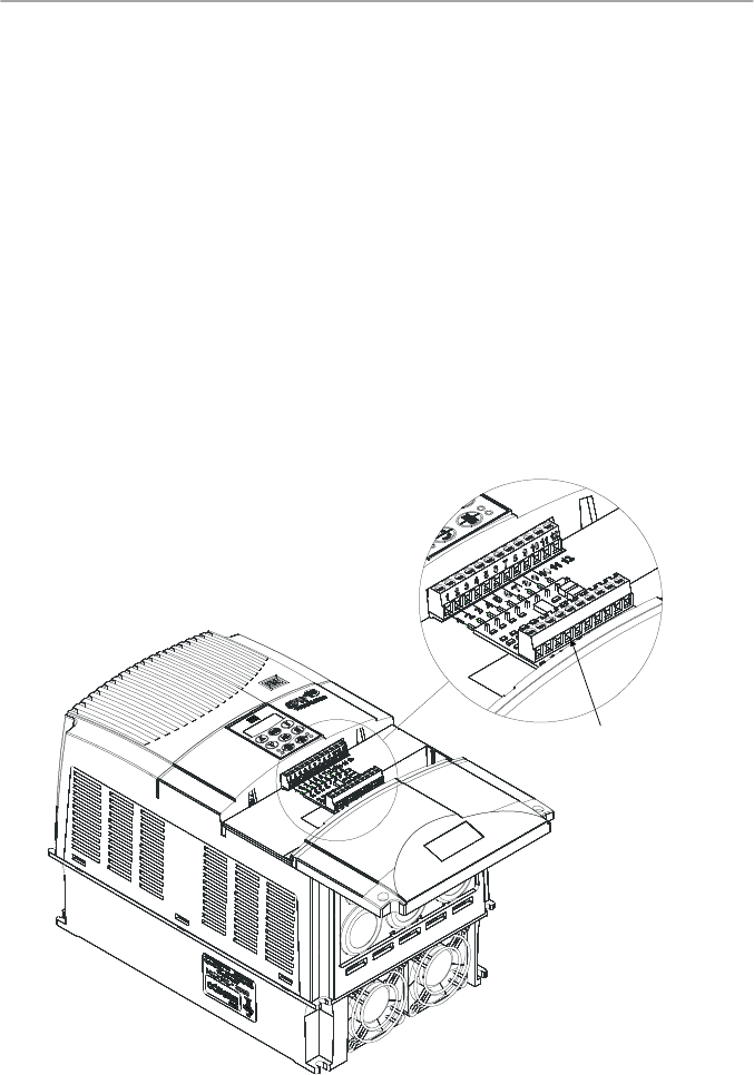
162
CHAPTER 8 - CFW-08 OPTIONS AND ACCESSORIES
8.16
KAC-120-CFW08
KAC-120-CFW08-N1M1
KAC-120-CFW08-N1M2
This optional is used to operate the digital inputs with alternate
voltage (120 Vac).
This board shall be externally connected to the control board
and the function of each terminal is described in the optional
itself. For safety purposes, the Nema 1 kit shall be used along
with this optional. Therefore, the following models can use this
optional:
KAC-120-CFW08
(only 120 Vac board):
Models: 22-28-33 A/200-240 V and 13-16-24-30A/380-480 V
KAC-120-CFW08-N1M1
(120 Vac board and KN1-CFW08-
M1):
Models: 1.6-2.6-4.0-7.0 A/200-240 V and 1.0-1.6-2.6-4.0 A/
380-480 V
KAC-120-CFW08-N1M2
(120 Vac board and KN1-CFW08-
M2):
Models: 7.3-10-16 A/200-240 V and 2.7-4.3-6.5-10 A/
380-480 V
Figure 8.23 -
KAC-120-CFW08
Detail of the
KAC-120-CFW08
board
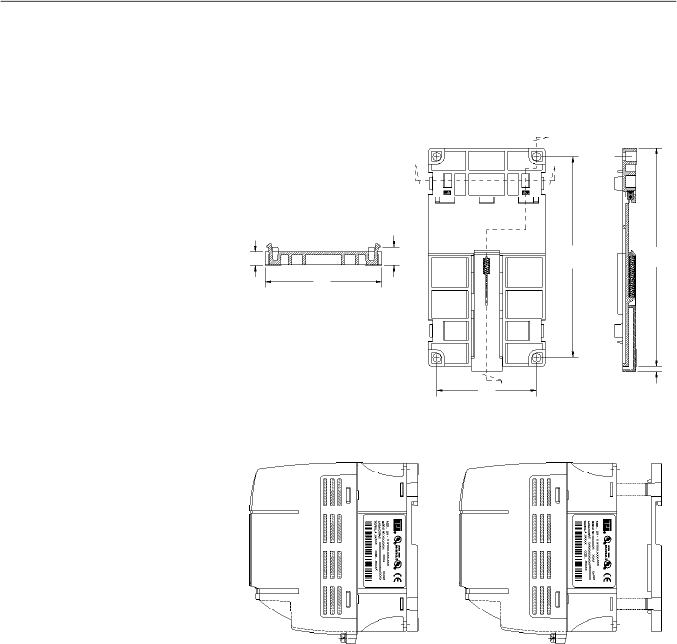
163
CHAPTER 8 - CFW-08 OPTIONS AND ACCESSORIES
8.17
KMD-CFW08-M1
This device must be used when the installation of the inverter
on 35 mm (1.38 in) rail, according to DIN EN 50.022, is desired
Only available for the models: 1.6-2.6-4.0-7.0 A/ 200-240 V
and 1.0-1.6-2.6-4.0A/380-480 V
Figure 8.24
- Inverter with DIN rail kit (KMD-CFW08-M1),
dimensions in mm [in]
Section A-A
Front View
Section B-B
B
B
A'
A
64
[2.52]
140
[5.51]
129
[5.08]
12
[0.47]
9
[0.35]
75
[2.95]
4
[0.16]
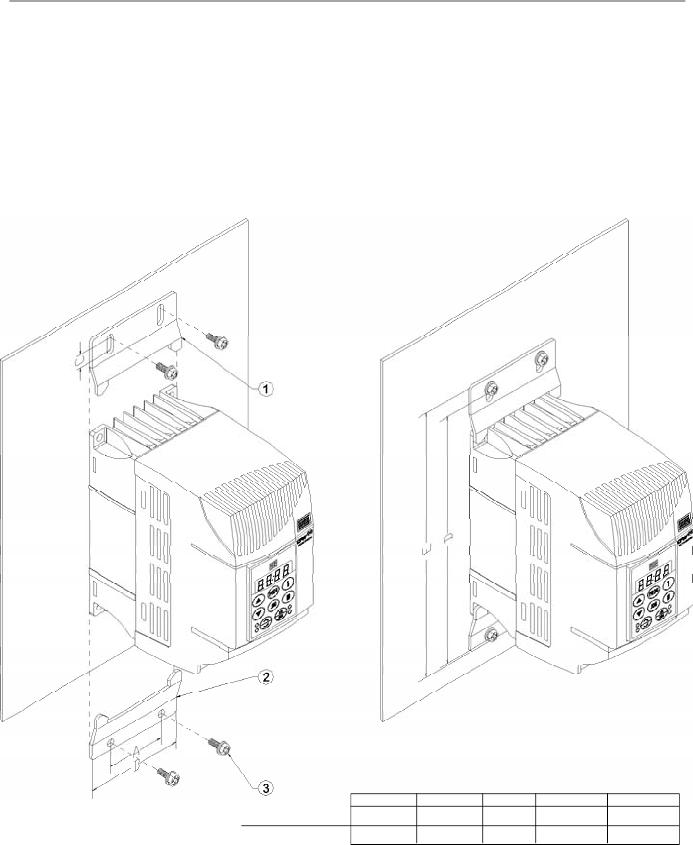
164
CHAPTER 8 - CFW-08 OPTIONS AND ACCESSORIES
This kit must be used when a better access to the screw hole
of the inverter is needed. Models that use this kit:
KFIX-CFW08-M1
Models: 1.6-2.6-4.0-7.0 A/200-240 V; 1.0-1.6-2.6-4.0 A/
380-480 V
KFIX-CFW08-M2
Models: 7.3-10-16 A/200-240 V; 2.7-4.3-6.5-10 A/380-480 V
8.18
KFIX-CFW08-M1
KFIX-CFW08-M2
Figure 8.25 -
Dimensions of the inverter with the KFIX-CFW08-MX kit
Dimensions in mm (in)
A
B
C
D
E
50 (1.97)
75 (2.95)
8 (0.31)
180 (7.09)
190 (7.48)
80 (3.15)
115 (4.53)
8 (0.31)
228 (8.98)
238 (9.37)
KFIX-CFW08-M1
KFIX-CFW08-M2
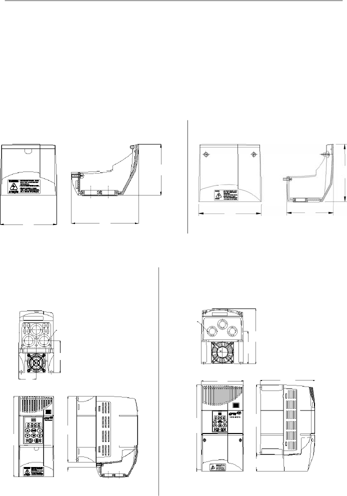
165
CHAPTER 8 - CFW-08 OPTIONS AND ACCESSORIES
a) Inverters 1.6-2.6- 4.0-7.0/220-240 V;
1.0-1.6-2.6-4.0/380-480 V with KN1-CFW08-M1
b) Inverters 7.3-10-16A/200-240 V;
2.7-4.3-6.5-10 A/380-480 V with KN1-CFW08-M2
This kit is used when a Nema 1/IP20 degree of protection is
desired for the inverter or when wiring metallic conduits for
the inverter are desired.
Models that use this kit:
KN1-CFW08-M1:
Models: 1.6-2.6-4.0-7.0/220-240 V; 1.0-1.6-2.6-4.0/380-480 V
KN1-CFW08-M2:
Models: 7.3-10-16 A/200-240 V; 2.7-4.3-6.5-10 A/380-480 V
Models 13 and 16 A/380-480 V have Nema 1/IP20 degree of
protection in the standard version.
8.19
KN1-CFW08-M1
KN1-CFW08-M2
Figure 8.26 a) and b)
- Dimensions in mm [in] of the Nema 1/IP20 kits
a) KN1-CFW08-M1
b) KN1-CFW08-M2
68
[2.68]
75
[2.95]
89
[3.5]
106
[4.17]
115
[4.53]
86
[3.39]
Figure 8.27 a) and b)
- External dimensions in mm [in] of the inverter with Nema 1/IP20 kit
Bottom View
Frontal View
Right Side View
Frontal View
Bottom View
Right Side View
68 [2.68]
38 [1.5]
22.5
[0.89]
141 [5.55]
172 [6.77]
10
[0.39]
45
[1.77]
22
[0.87]
115 [4.53]
150 [5.9]
190 [7.48]
234 [9.21]
150 [5.9]
89 [3.5]

166
CHAPTER 8 - CFW-08 OPTIONS AND ACCESSORIES
8.
20
RFIFIL
TER
The installation of frequency inverters requires some care in
order to prevent electromagnetic interferences (EMI).
This electromagnetic interference may disturb the operation
of the inverter itself or other devices, such as electronic
sensors, PLCs, transducers, radio equipment, etc. installed
in the proximity.
To avoid these troubles, follow the installation instructions
contained in this manual.
In these cases, avoid the installation of electromagnetic noise
generating circuits, such as power cables, motors, etc. near
to signal or control cables.
Care should also be taken with the radiated interference, by
shielding the cables and the circuits that tend to emit
electromagnetic waves and can cause interference.
The electromagnetic interference can also be transmitted
through power supply line. This type of interference is
minimized in the most cases by capacitive filters which are
alreadyinstalled inside the CFW-08.
However, when inverters are installed in residential areas, the
installation of additional filter may be required.
These filters may be installed internally (on some types) or
externally.
As defined in standards, the Category C1 filter has more
attenuation capacity than the Category C2 filter , thus being
more suitable for residential areas.
Item 8.1 lists the availableRFI filters with the respective inverter
models.
The inverters with internal CategoryC2 filters have the same
external dimensions as the inverters without filter.
The external Category C1 filters must be installed between
the power supplyline and the inverter input, asshown in figure
8.28.
Instructions for the RFI filter installation:
I
nstall the inverter and the filter on a metallic grounded
plate as near to each other as possible and ensure a
good electrical contact between the grounded plate and
the inverter and filter frames.
For motor connection use a shielded cable or individual
cables inside a grounded metallic conduit.
NOTE!
For installations that must meet the European standards refer
to item 3.3.
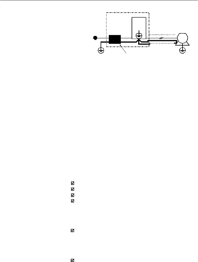
167
CHAPTER 8 - CFW-08 OPTIONS AND ACCESSORIES
Power
Supply
Ground
Filter
CFW-08
Driving Panel
Conduit or
Shielded
Cable
Motor
Motor Ground
(frame)
PE
PE
Figure 8.28
- Connection of the external RFI filter - Category C1
8.21
LINE REACTOR
Due to the input circuit characteristic, common to the most
inverters available on the market, consisting of a diode rectifier
and a capacitor bank, the input current (drained from the power
supply line) of inverters is a non sinusoidal waveform and
contains harmonics of the fundamental frequency (frequency
of the power supply - 60 Hz or 50 Hz).
These harmonic currents circulate through the power supply
line and cause harmonic voltage dropswhich distort the power
supply voltage of the inverter and other loads connected to
this line. These harmonic currents and voltage distortions may
increase the electrical losses in the installation, overheating
the components (cables, transformers, capacitor banks,
motors, etc.), as well as lowering the power factor.
The input current harmonics are determined by the value of
the impedances present at the input circuit.
The installation of a line reactor reduces the harmonic content
of the input current, providing the following advantages:
Increasing the input power factor.
Reduction of the RMS input current.
Reduction of the power supply voltage distortion.
Increasing the life of the DC link capacitors.
Install it as close as
possible to the inverter
8.21.1
Application Criteria
In a general manner, the CFW-08 series inverters can be
connected directly to thepower supplyline withoutline reactors.
But in this case, ensure the following:
To ensure the inverter expected life, a minimum line
impedance that introduces a voltage drop as shown in table
8.3, as a function of the motor load, is recommended. If the
line impedance (transformers and wirings) is lower than
these values, it is recommended to use line reactor(s).
When it is necessary to add a line reactor to the system, it
is recommended to size it considering a 2 % to 4 % voltage
drop (for nominal output current). This pratice results in a
compromise between motor voltage drop, power factor
improvement and harmonic current distortion reduction.
This practice results in a compromise between motor
voltage drop, power factor improvement and harmonic
current distortion reduction.

168
CHAPTER 8 - CFW-08 OPTIONS AND ACCESSORIES
[
H]
L = 1592 x
V
x
V
e
f I
S, nom
where:
V
- desired line voltage drop, in percentage (%);
V
e
- phase voltage
at inverter input (line voltage),
given in Volts (V);
I
s,nom
- rated inverter outputcurrent;
f
- line frequency.
Model
1.6 A / 200-240 V
2.6 A / 200-240 V
4.0 A / 200-240 V
7.0 A / 200-240 V
7.3 A / 200-240 V
10 A / 200-240 V
16 A / 200-240 V
22A/200-240 V
28A/200-240 V
33A/200-240 V
1.0 A / 380-480 V
1.6 A / 380-480 V
2.6 A / 380-480 V
2.7 A / 380-480 V
4.0 A / 380-480 V
4.3 A / 380-480 V
6.5 A / 380-480 V
10 A / 380-480 V
13 A / 380-480 V
16 A / 380-480 V
24A/380-480 V
30A/380-480 V
With Rated Load
at the Inverter Output
(I
S
= I
S,nom
)
0.25 %
0.1 %
1.0 %
0.5 %
1.0 %
0.5 %
1.0 %
2.0 %
1.0 %
1.0 %
0.05 %
0.05 %
0.1 %
0.25 %
1.0 %
1.0 %
0.5 %
0.5 %
0.5 %
1.0 %
1.0 %
1.0 %
With 80 % of the
Rated Load
(I
S
= 0.8I
S,nom
)
0.1 %
0.05 %
0.5 %
0.25 %
0.25 %
0.25 %
0.5 %
1.0 %
0.5 %
0.5 %
0.05 %
0.05 %
0.05 %
0.1 %
0.5 %
0.5 %
0.25 %
0.25 %
0.25 %
0.5 %
0.5 %
0.5 %
With 50 % of the
Rated Load
(I
S
= 0.5I
S,nom
)
0.05 %
Minimum Line Impedance
Always add a line reactor when capacitors for power factor
correction are installed in the same line and near to the
inverter.
Figure 8.29 shows the line reactor connection to the input.
Use the following equation to calculate the value of the line
reactor necessary to obtain the desired percentage of the
voltage drop:
T
able 8.3
- Minimum network impedance for several load conditions
Note:
These values ensure a life of 20,000 hour for the DC link capacitors, i.e., they
can be operated during 5 years with operation of 12 hours per day.
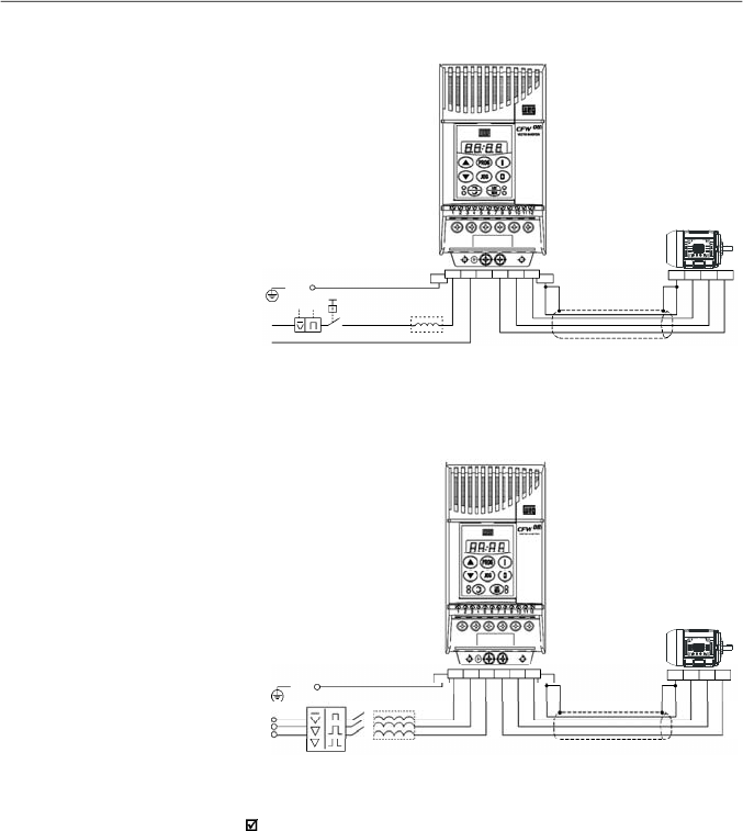
169
CHAPTER 8 - CFW-08 OPTIONS AND ACCESSORIES
a) Single-phase power supply models
b) Three-phase power supply models
Figur
e
8.
29 b)
-
Power connection with line reactor at the input
L
PE
P E
R
U
V
W
P E
Q1
S
T
U
V
W
P E
Line
N
Shield
Shield
P E
U
V
W
R
S
T
R
P E
S
T
U
V
W
P E
Line
PE
Figur
e 8.29
a)
-
Power connection with line reactor at the input
As an alternative criterion, we recommend to add a line reactor
always the transformer that supplies the inverter has rated
power higher than indicated in table 8.4.

170
CHAPTER 8 - CFW-08 OPTIONS AND ACCESSORIES
Table 8.4
- Alternative criteria for use of line reactor - maximum values of the
transformer power
TransformerApparent Power [kVA]
1.6 A and 2.6 A/200-240 V
4A/200-240 V
7 A and 7.3 A/200-240 V
10A/200-240 V
16-22-28Aand 33 A/200-240 V
1 A-1.6 A and 2.6 A/380-480 V
4.0 A and 4.3 A/380-480 V
2.7 A/380-480 V
6.5-10 A and 13 A/380-480 V
16-24 A and 30 A/380-480 V
30 x rated inverter apparent power [kVA]
6 x rated inverter apparent power [kVA]
10 x rated inverter apparent power [kVA]
7.5 x rated inverter apparent power [kVA]
4 x rated inverter apparent power [kVA]
30 x rated inverter apparent power [kVA]
6 x rated inverter apparent power [kVA]
15 x rated inverter apparent power [kVA]
7.5 x rated inverter apparent power [kVA]
4 x rated inverter apparent power [kVA]
Inverter Model
Note:
The value for the rated apparent power can be obtained in
item
9.1 of this
manual.
The use of a three-phase load reactor, with an approximate 2 %
voltage drop, adds an inductance at the inverter PWM output
to the motor. This decreases the dV/dt (voltage rising rate) of
the pulses generated at the inverter output. This practice
reduces the voltage spikes on the motor windings and the
leakage currents that may be generated when long cables
between inverter and motor (as a function of the "transmission
line" effect) are used.
Thereare manyfactors thatinfluence the peak level (Vp) and
the rise time (tr) of voltage spikes: cable type, cable length,
motor size, switching frequency and so on.
WEG recommends using a load reactor when the supply
voltage is higher than 500 V, though this is not always required.
WEG, as a specialist in both motors and inverters (VSDs) is
able to provide an integrated solution.
The load reactor value is calculated in the same way as the
line reactor (refer to item 8.21.1).
If the cables between inverter and motor are longer that 100 m
(300 ft), the cable capacitance to ground maycause nuisance
overcurrent (E00) trips. In this case it is also recommended to
use a load reactor.
8.22
LOAD REACTOR
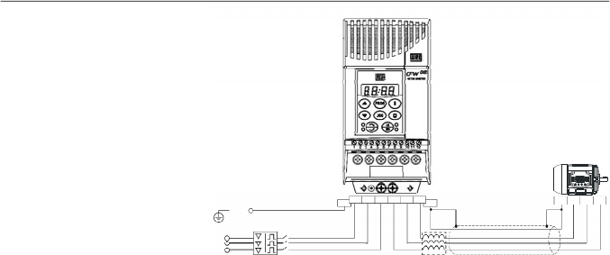
171
CHAPTER 8 - CFW-08 OPTIONS AND ACCESSORIES
8.23
DYNAMIC BRAKING
The dynamic braking is used where short deceleration times
are required or where high inertia is present.
For the correct sizing of the braking resistor, application data
such as, deceleration time, load inertia, braking duty cycle
must be considered.
In anycase, the rms current capacityand the maximum peak
current must be considered.
The maximum peak current defines the minimum permitted
ohmic value for the braking resistor. Refer to table 8.5.
The DC link voltage level for the actuation of the dynamic
braking is as follows:
Inverters supplied with 200 V to 240 V:
375 Vdc
Inverters supplied with 380 V to 480 V:
750 Vdc
8.23.1
Resistor Sizing
The braking torque, thatcanbe obtained through the frequency
inverter,without using the dynamic braking module, varies from
10 % to 35 % of the rated motor torque.
During the deceleration process, the kinetic energy of the load
is regenerated into the inverter DC link. This energy loads up
the capacitors by increasing the DC link voltage. When this
energy is not fully dissipated, it may generate a DC link
overvoltage trip (E01) and disabling the inverter.
To obtain higher braking torques, the use of dynamic braking
is recommended where the excessof the regenerated energy
is dissipated in a resistor mounted externally to the inverter.
The braking resistor is defined according to the deceleration
time, load inertia and resistive torque.
In most cases, a resistor with an ohmic value as indicated on
the table belowand a power rating of 20 % of the driven motor
can be used.
Use wire type or tape type resistors with suitable insulation to
withstand the instantaneous current peaks.
Figure 8.30
- Load reactor connection
R
S
T
PE
PE
R
S
T
U
V
W
U
V
W
PE
Disconnecting
Switch
PE
Load
Reactor
Shield
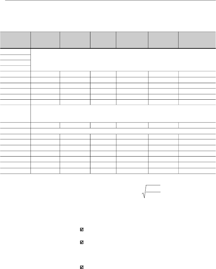
172
CHAPTER 8 - CFW-08 OPTIONS AND ACCESSORIES
Table 8.5
- Recommended braking resistors
8.23.2
Installation
Con
nect the braking resistor between the
+UD
and
BR
power terminals (refer to item 3.2.1).
Make this connection with a twisted pair. Separate this
cable from any signal or control wire
.
Size the cable cross
section according to the application, by considering the
maximum current and the rms current.
If the braking resistor is installed inside the inverter panel,
consider the heat dissipated by the resistor when defining
the panel ventilation.
For critical applications with very short braking times, high
inertia loads (ex.: centrifuges) or with very short and frequent
duty cycles, contact WEG to define the mostsuitable resistor.
Inverter Model
1.6 A/ 200-240 V
2.6 A/ 200-240 V
4.0 A/ 200-240 V
7.0 A/ 200-240 V
7.3 A/ 200-240 V
10A / 200-240 V
16A / 200-240 V
22A / 200-240 V
28A / 200-240 V
33A / 200-240 V
1.0 A/ 380-480 V
1.6 A/ 380-480 V
2.6 A/ 380-480 V
2.7 A/ 380-480 V
4.0 A/ 380-480 V
4.3 A/ 380-480 V
6.5 A/ 380-480 V
10A / 380-480 V
13A / 380-480 V
16A / 380-480 V
24A / 380-480 V
30A / 380-480 V
Maximum
BrakingCurrent
10 A
15 A
20 A
26 A
26 A
38 A
6 A
6 A
8 A
16 A
24 A
24 A
35 A
43 A
RMS
Braking
Current
(*)
5 A
7 A
10 A
13 A
18 A
18 A
3.5 A
3.5 A
4 A
10 A
14 A
14 A
21 A
27 A
Recommended
Resistor
39
27
22
15
15
10
127
127
100
47
33
33
22
18
Recommended
Wiring
2.5 mm
2
/ 14 AWG
2.5 mm
2
/ 14 AWG
4
mm
2
/ 12 AWG
6 mm
2
/ 10 AWG
6 mm
2
/ 10 AWG
6 mm
2
/ 10 AWG
1.5
mm
2
/ 16 AWG
1.5
mm
2
/ 16 AWG
2.5 mm
2
/ 14 AWG
4
mm
2
/ 12 AWG
6
mm
2
/ 10 AWG
6
mm
2
/ 10 AWG
6
mm
2
/ 10 AWG
6
mm
2
/ 10 AWG
P
max
(Maximum
Resistor Power)
3.9 kW
6.1 kW
8.8 kW
10.1 kW
10.1 kW
14.4 kW
4.6 kW
4.6 kW
6.4 kW
12 kW
19 kW
19 kW
27 kW
33 kW
P
rated
(Rated
Resistor Power)
0.98 kW
1.3 kW
2.2 kW
2.5 kW
3.2 kW
3.2 kW
1.6 kW
1.6 kW
1.6 kW
4.7 kW
6.5 kW
6.5 kW
7.9 kW
10.9 kW
Braking not available
Braking not available
Braking not available
(*)
The rms braking current can be determined by:
where t
br
corresponds to the sum of the braking times during the most
severe 5 minute cycle.
I
rms
=
I
max
.
t
br
[min]
5
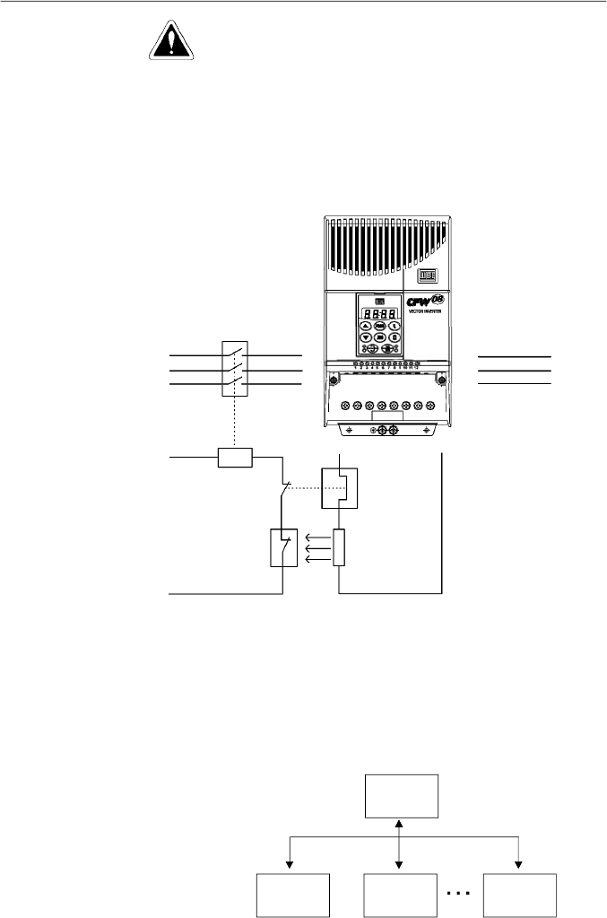
173
CHAPTER 8 - CFW-08 OPTIONS AND ACCESSORIES
Figure 8.31
- Braking resistor connection
(only for models 7.3-10-16 A/200-240 V and 2.7-4.3-6.5-10-13-16 A/380-480 V)
8.24
SERIAL
COMMUNICATION
8.24.1
Introduction
MOTOR
POWER
SUPPLY
CONTACTOR
CONTROL
POWER
SUPPLY
OVERLOAD
RELAY
THERMOSTAT
BRAKING
RESISTOR
U
V
W
R
S
T
BR
+UD
The basic objective of the serial communication is the physical
connection of the inverters in an equipment network configured
as follows:
DANGER!
The internal inverter braking circuit and the braking resistor
can be damaged when not correctly sized or when the line
voltage exceeds the maximum allowed value.
In this case, the only guaranteed method to avoid burning the
braking resistor and eliminate risk of fire is the installation of a
thermal overload relay in series connected with the resistor
and/or the installation of a thermostat on the resistor body,
wiring it in such a way that it disconnects the inverter power
supply in case of overheating, as shown in figure 8.31:
Master
PC, PLC,
etc.
Slave 1
(Inverter)
Slave 2
(Inverter)
Slave n
(Inverter)
n
30

174
CHAPTER 8 - CFW-08 OPTIONS AND ACCESSORIES
-IDENTIFICATION
network address;
inverter;
software version.
- CONTROL
general enabling/disabling;
enabling/disabling by ramp;
direction of rotation;
frequency/speed reference;
local/remote;
JOG;
error and fault RESET.
- STATUS RECOGNITION
ready;
Sub;
run;
local/remote;
error;
JOG;
direction of rotation.
- PARAMETER READING
- CHANGE OF PARAMETERS
Typical examples of network use:
PC (master) for the parametrization of one or several
inverters at the same time;
SDCD monitoring inverter variables;
PLC controlling the operation of one or more inverters in a
industrial process.
The physical connection between the inverters and the master
is performed according to one of the standards below:
a. RS-232 (point to point up to 10 m (32.8 ft)).
b.
RS-485(multipoint,galvanicisolation,upto 1000m(3280.8ft)).
8.24.2
RS-485 and
RS-232 Interfaces
Description
The inverters have a control software for data transmission/
reception through serial interface, thus facilitating the reception
of data thathave been sent bythe masterand the transmission
of the data requested by the master.
Thissoftwaresupports WEGprotocolandninedifferentModbus-
RTU modes, that can be selected via parameter P312. The
subjects broached in this
item
refers toWEG protocol. Formore
details about the Modbus-RTU,
refer to
item 8.25.
The transfer rate is 9600 bits/s, following an exchange protocol
of question/answertypebyusingASCIIcharacters.
The master is able to realize the following operations related to
eachinverter:

175
CHAPTER 8 - CFW-08 OPTIONS AND ACCESSORIES
ADDRESS
(P308)
0
1
2
3
4
5
6
7
8
9
10
11
12
13
14
15
16
17
18
19
20
21
22
23
24
25
26
27
28
29
30
31
ASCII
CHAR
DEC
HEX
@
64
40
A
65
41
B
66
42
C
67
43
D
68
44
E
69
45
F
70
46
G
71
47
H
72
48
I
73
49
J
74
4A
K
75
4B
L
76
4C
M
77
4D
N
78
4E
O
79
4F
P
80
50
Q
81
51
R
82
52
S
83
53
T
84
54
U
85
55
V
86
56
W
87
57
X
88
58
Y
89
59
Z
90
5A
]
91
5B
\
92
5C
[
93
5D
^
94
5E
_
95
5F
This interface permits the linkage of up to 30 inverters to a
master (PC, PLC, etc.), attributing and setting for each inver-
ter an address (1 to 30). In addition to these 30 addresses,
there are two addresses to perform special tasks:
Address 0:
any inverter in the network is inquired,
independently of its address. Only one inverter can be
connected to the network (point to point) in order to prevent
short-circuits in the line interface.
Address 31:
a control can be transmitted to all inverters in
thenetworksimultaneously
, without acceptance recognition.
List of addresses and corresponding ASCII characters:
8.24.2.1
RS-485
Table 8.6
- Adresses and corresponding ASCII characters list

176
CHAPTER 8 - CFW-08 OPTIONS AND ACCESSORIES
The connection between the network participants is performed
through a pair of wires. The signal levels are according to the
EIA RS-485 STANDARD with differential receivers and
transmitters.You must use the serial communication module
KRS-485-CFW08 (refer to item 8.13).
Whenthe masterisfitted only with a RS-232 serial interface, you
mustapplya level conversion module from RS-232 to RS-485.
In this case we have the connection of a master to an inverter
(point to point). The data can be exchanged in a bi-directional
way, but not simultaneously (HALF DUPLEX).
The logical levels meet the EIA RS-232C STANDARD, that
specifies the use of balanced signals. In this case one wire is
used for the transmission (TX), one wire for the reception (RX)
and one wire for the return (0 V).This configuration is a three
wire economy model.
You must use the RS-232 (KCS-CFW08) module in the inver-
ter (refer to item 8.11).
The items of this section describe the protocol used in the
serial communication.
Parameters: are those existing in the inverters whose
visualization or alteration is possible through the keypad
(HMI) interface.
Variables: are values that have specific functions in the
inverter and that can be read and, in some cases,modified
by the master.
8.24.2.2
RS-232
8.24.3
Definitions
8.24.3.1
Used Terms
Other ASCII characters used by the protocol:
ASCII
CODE
DEC
HEX
0
48
30
1
49
31
2
50
32
3
51
33
4
52
34
5
53
35
6
54
36
7
55
37
8
56
38
9
57
39
=
61
3D
STX
02
02
ETX
03
03
EOT
04
04
ENQ
05
05
ACK
06
06
NAK
21
15
Table 8.7
- Others ASCII characters used by the protocol
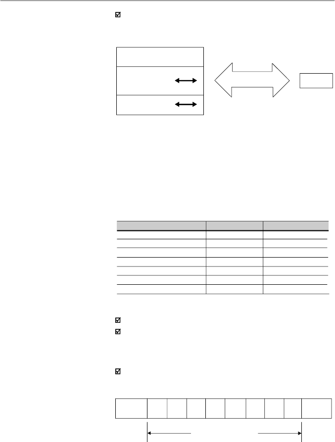
177
CHAPTER 8 - CFW-08 OPTIONS AND ACCESSORIES
SCHEMATIC DIAGRAM:
INVERTER
BASIC
VARIABLES
PARAMETERS
MASTER
SERIALCONNECTION
VARIABLES
8.24.3.2
Parameter/
Variables
Resolution
1 start bit;
8
information
bits [
they codify text characters and
transmission characters, removed from the 7 bits code,
according to ISO 646 and complemented for the even parity
(eighth bit)];
1 stop bit.
After the start bit, follows the less significant bit:
8.24.3.3
Character
Format
Unit
Hz
A
V
s
%
-
rpm
Resolution
0.01 Hz/unit
0.01 A/unit
1 V/unit
0.1 s/unit
0.01 %/unit
0.01/unit
1 rpm/unit
Variable
Frequency
Current
(AC or DC)
Voltage
(AC or DC)
Time
Percentage
Gain
rpm
The variables and the parameters have 16 bits format, i. e.,
from -32767 to +32768 for signed variables or from 0 to 65535
for unsigned variables.
All variables are considered as signed variables, except those
related to time (time, period, frequency).
In addition, the maximum and minimum values must consider
the parameter range limits.
The table below shows the main variables and their respective
resolutions.
START
B1
B2
B3
B4
B5
B6
B7
B8
STOP
Start
bit
Stop
bit
8 bits of information
8.24.3.4
Protocol
The transmission protocol meets the Standard ISO 1745 for
the transmission in code.
Onlytext character sequences without headers are used. The
error/fault monitoring is made through transmission related to
the parity of the individual 7 bit characters, according to ISO
646. The parity monitoring is made according to DIN 66219
(even parity). The master uses two types of messages:
Basic variables: are those that can be accessed only
through the serial interface.
Table 8.8
- S
erial communication resolutions
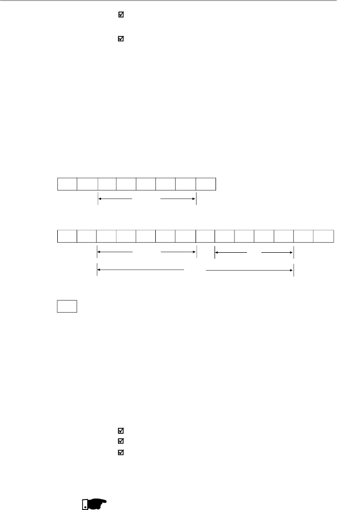
178
CHAPTER 8 - CFW-08 OPTIONS AND ACCESSORIES
Reading message:
for inquiring of the inverter variable
content;
Writing message:
to change the inverter variable content
or to send comands to the inverters.
Note:
No transmission between two inverters is possible.
The master has the bus access control.
Reading message:
This message allows the master to receive from the inverter
the content corresponding to the inquiry code. In the answer
message, the inverter transmits the data requested by the
master and it finishes the transmission with EOT.
2)Inverter:
ADR STX
= xH xH xH xH ETX BCC
CODE
VAL
(HEXADECIMAL)
TEXT
EOT ADR
ENQ
CODE
Format of the reading message:
EOT:
control character of End Of Transmission;
ADR:
inverter address (ASCII@,A, B, C, a ) (ADdRess);
CODE:
address of the 5-digit variable coded in ASCII;
ENQ:
control character ENQuiry (enquiry).
Format of the inverter answer message:
ADR:
1 character - inverter address;
STX:
control character - Start of TeXt;
TEXT:
consists in:
CODE:
address of the variable;
“ = “:
separation character;
VAL:
4 digits value HEXADECIMAL;
ETX:
control character - End of Text;
BCC:
CheCksum Byte - EXCLUSIVE OR of all bytes between
STX (excluded) and ETX (included).
NOTE
!
In some cases there can be an inverter answer with:
3) Master:
EOT
1) Master:
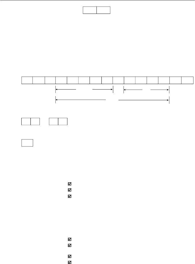
179
CHAPTER 8 - CFW-08 OPTIONS AND ACCESSORIES
Writing message
This message sends data to the inverter variables. Theinver-
terwill answer by indicating if the data havebeen accepted or
not.
Format of the writing message:
EOT:
control character of End Of Transmission;
ADR:
inverter address;
STX:
control character - Start of TeXt;
TEXT:
consists in:
CODE:
variable address;
“ = “:
separation character;
VAL:
4 HEXADECIMAL digit values;
ETX:
control character - End of TeXt;
BCC:
CheCksum Byte - EXCLUSIVE OR of all the bytes
between STX (excluded) and ETX (included).
Format of the inverter answer message:
Acceptance:
ADR:
inverter address.
ACK:
ACKnowledge control character.
Without acceptance
:
ADR:
inverter address.
NAK:
NotAcKnowledge control character.
This means that the data were not accepted and the
addressed variable continues with its old value.
ADR
NAK
Refer to the item 8.24.3.5.
1) Master:
EOT ADR STX
= xH xH xH xH
ETX
BCC
CODE
VAL
(HEXADECIMAL)
TEXT
2)Inverter:
ADR NAK
ADR ACK
or
3) Master:
EOT
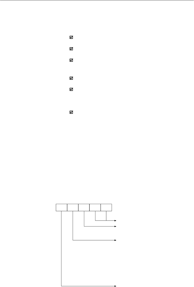
180
CHAPTER 8 - CFW-08 OPTIONS AND ACCESSORIES
8.24.3.6
Message
Sequence
8.24.3.7
Variable Code
CODE
Number of the basic variable or parameter
Equipment number:
"7" = CFW08
"9" = any inverter
Specifier:
0 = basic variables
1 = P000 to P099
2 = P100 to P199
3 = P200 to P299
4 = P300 to P399
5 = P400 to P499
6 = P500 to P599
7 = P600 to P699
The inverter and the master test the message syntax.
Theanswersfor the respective verified conditions are defined
as follows:
Reading message:
No answer: with wrong message structure, control
characters received incorrectly or wrong inverter address;
NAK:
C
ode
correspond
ing to a non existing
vari
able or there
is only a writing variable;
TEXT:
with valid messages.
Writing message:
No answer: with wrong message structure, control
characters received incorrectly or wrong inverter address;
NAK
:C
ode
correspond
ing to a non existing
vari
able, wrong
BCC (checksum byte), only reading variable, VAL out of
the allowed range for the respective variable, operation
parameter out of the alteration
mode;
ACK
: with valid message.
The master should maintain, between two variable
transmissions to the same inverter, a waiting time that is
compatible with the used inverter.
The messages are processed in the inverter in determined
intervals of time.
Therefore, a pause larger than the sum of the times T
proc
+ T
di
+ T
txi
should be ensured between two messages addressed
to the same inverter (refer to item 8.24.6).
The field designated with CODE determines the parameter
address and the basic variables formed by 5 digits (ASCII
characters) as follows:
Equal to zero (0)
X X X
X
X
8.24.3.5
Execution and
Message Test
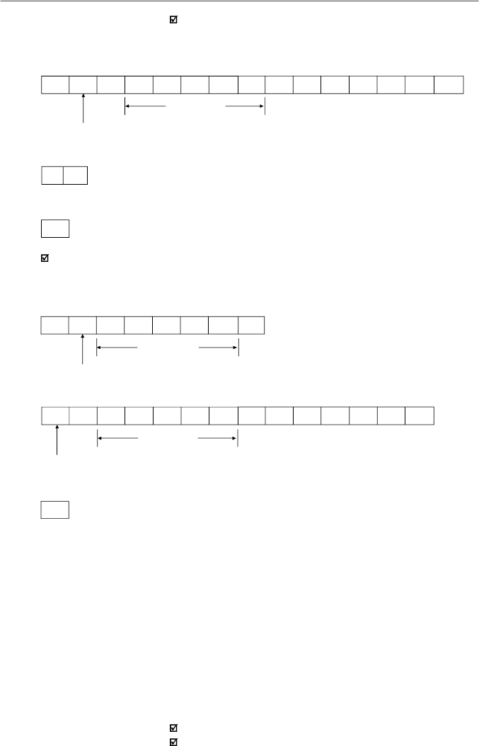
181
CHAPTER 8 - CFW-08 OPTIONS AND ACCESSORIES
3) Master:
EOT
Reading of the output current from the inverter 10
(sup
posing that the same was at
7
.
8
A
at the moment of the enquiry
).
1) Master:
EOT J
0 1
7
0
3 ENQ
P003 Code
addr.10
2)Inverter:
P003 Code
P003 = 30CH = 780 = 7.8/0.01
addr.10
3) Master:
EOT
J
STX
0
1
7
0
3
=
0H
3H
0H
CH
ETX
BCC
8.24.4
Message
Examples
Change of the minimum frequency
(P133)
to
6
.
00
Hz
in the
inverter
7.
1) Master:
F
min
F
min
= 258H = 600 = 6.00/0.01
addr. 7
2)Inverter:
G
ACK
EOT
G
STX
0
2
7
3
3
=
0H
2H
5H
8H
ETX
BCC
8.24.5
Variables and
Errors
of the Serial
Communication
8.24.5.1
Basic Variables
V00 (code 00700)
Indication of the inverter model (reading variable):
The reading of this variable permits the identification of the
inverter type. For the CFW-08 this value is 7, as defined in
8.24.3.7.
V02 (code 00702)
Indication of the inverter status (reading variable):
Logical status (byte-high).
Error code (byte-low).

182
CHAPTER 8 - CFW-08 OPTIONS AND ACCESSORIES
EL8:
0 = ramp enabling (start/stop) inactive
1 = ramp enabling active
EL9:
0 = general enabling inactive
1 = general enabling active
EL10:
0 = reverse
1 = forward
EL11:
0 = JOG inactive
1 = JOG active
EL12
0 = local
1 = remote
EL13:
0 = without undervoltage
1 = with undervoltage
EL14 :
not used
EL15:
0 = without error
1 = with error
Inverter
enabled
EL8 =
EL9 = 1
}
Error code:
hexadecimal error number
Ex.:
E00 00H
E01 01H
E10 0AH
V03 (code 00703)
Selection of the logical control:
Writing variable, whose bits have the following meaning:
BYTE HIGH:
desired action mask. It order to enable the
action, the corresponding bit should be set to 1.
CL8: 1 = enabling ramp (start/stop)
CL9: 1 = general enabling
CL10: 1 = forward/reverse rotation
CL11: 1 = JOG
CL12: 1 = local/remote
CL13: not used
CL14: not used
CL15: 1 = inverter “RESET”
Where:
Logical status:
EL15
EL14
EL13
EL12
EL11
EL10
EL9
EL8
CL15
CL14
CL13
CL12
CL11
CL10
CL9
CL8
MSB
LSB
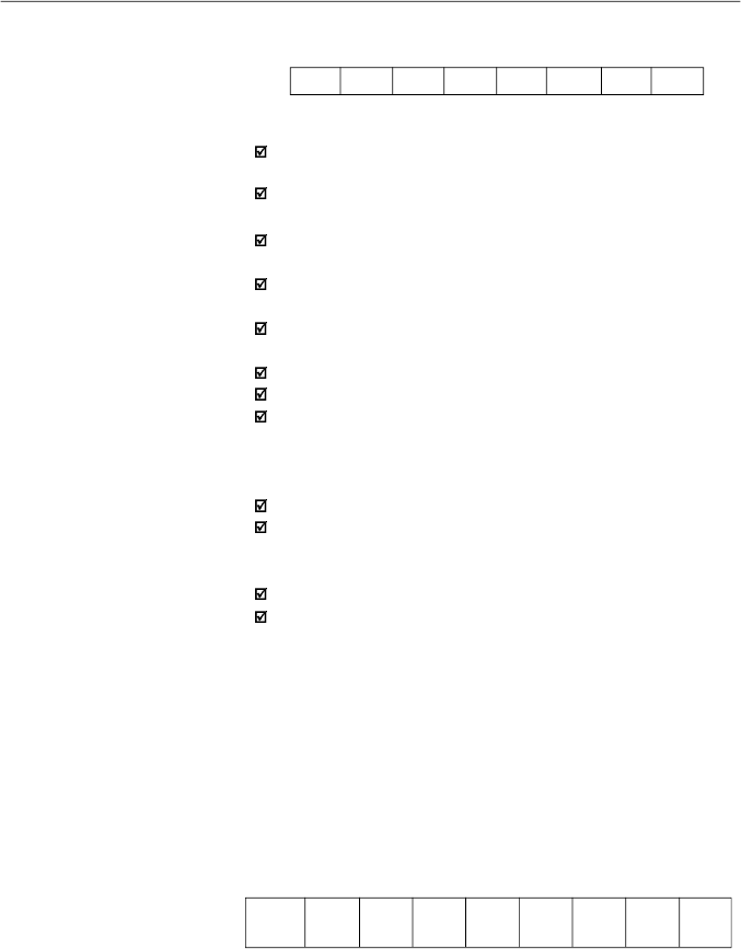
183
CHAPTER 8 - CFW-08 OPTIONS AND ACCESSORIES
BYTE LOW:
logical level of the desired action.
CL0:
1 = enabling (run)
0 = disabling by ramp (stop)
CL1:
1 = enabling
0 = general disabling (stops by inertia)
CL2:
1 = forward
0 = reverse
CL3:
1 = JOG active
0 = JOG inactive
CL4:
1 = remote
0 = local
CL5:
not used
CL6:
not used
CL7:
the transition in this bitfrom 0 to 1causes the inverter
“RESET” when any error condition is present
Notes:
Disabling via DIx has priorityover these disabling.
To disable the inverter via serial interface, set CL0 = CL1 =
CL8 = CL9 = 1, while the external disabling (example, via
DI) must be inactive.
If CL1 = 0 and CL9 = 1, it will occur general disabling.
If CL0 = 0 and CL8 = 1, the inverter will be disabled by ramp.
V04 (code 00704)
Frequency reference given by the Serial interface
(reading/writing variable):
Allows to send the frequency reference to the inverter, when
P221 = 5 in local mode and P222 = 5 in remote mode. The
variable resolution is shown in the item 8.24.3.2.
V05 (code 00705)
Enabled controls to the Serial interface (reading
variable):
CL7
CL6
CL5
CL4
CL3
CL2
CL1
CL0
MSB
LSB
CHSH
CHSL
CHSL
CHSL
CHSL
CHSL
CHSL
CHSL
CHSL
0
7
6
5
4
3
2
1
0
MSB
LSB
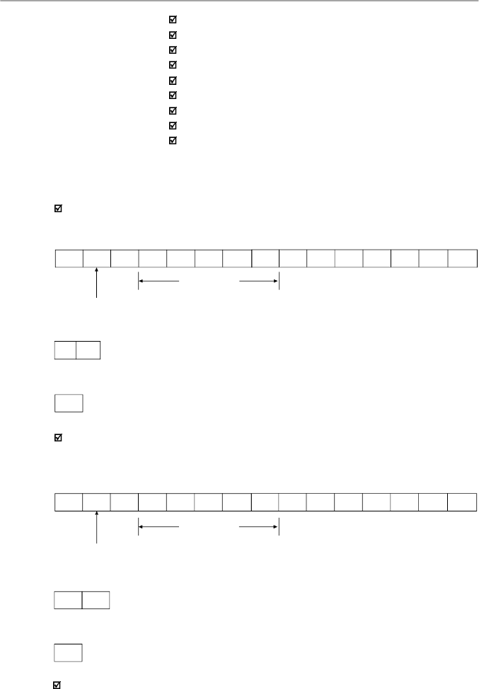
184
CHAPTER 8 - CFW-08 OPTIONS AND ACCESSORIES
Inverter enabling (provided P229 = 2 for LOC or P230 = 2 for REM).
8.24.5.2
Message Examples
with Basic Variables
CHSL0: 1 - serial local reference
CHSL1: 1 - serial local forward/reverse selection
CHSL2: 1 - serial local On/Off selection
CHSL3: 1 - serial local JOG
CHSL4: 1 - serial remote reference
CHSL5: 1 - serial remote forward/reverse selection
CHSL6: 1 - serial remote On/Off selection
CHSL7: 1 - serial remote JOG selection
CHSH0: 1 - serial local/remote selection.
Changing inverter from forward to reverse (provided P229 = 2 for LOC or P230 = 2
for REM) - if P231 = 2.
1) Master:
C. L. Code
general enabling = 1
ramp enabling = 1
addr. 7
2)Inverter:
G
ACK
3) Master:
EOT
EOT
G
STX
0
0
7
0
3
=
0H
3H
0H
3H
ETX
BCC
1) Master:
C. L. Code
Reverse = 0
addr. 7
EOT
G
STX
0
0
7
0
3
=
0H
4H
0H
0H
ETX
BCC
2)Inverter:
G
ACK
3) Master:
EOT
JOG enabling
(
provided
P22
9
=
2
for
LOC o
r
P2
30
=
2
for
REM)
.
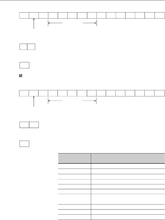
185
CHAPTER 8 - CFW-08 OPTIONS AND ACCESSORIES
8.24.5.3
Parameters
Related to the
Serial
Communication
Parameter Description
Local/Remote Selection
Local Reference Selection
Remote Reference Selection
Local Command Selection
Remote Command Selection
Forward/Reverse Selection
Inverter address on the Serial Communication
Network (value range from 1 to 30)
Serial Interface Protocol
Serial Interface Watchdog Action
Serial Interface Watchdog Timeout
Parameter Number
P220
P221
P222
P229
P230
P231
P308
P312
P313
P314
Error reset
1) Master:
C. L. Code
RESET = 1
addr. 7
2)Inverter:
G
ACK
3) Master:
EOT
EOT
G
STX
0
0
7
0
3
=
8H
0H
8H
0H
ETX
BCC
1) Master:
C. L. Code
JOG active = 1
addr. 7
2)Inverter:
G
ACK
EOT
G
STX
0
0
7
0
3
=
0H
8H
0H
8H
ETX
BCC
3) Master:
EOT
For further information about the parameter above, refer to
chapter 6 - Detailed Parameter Description.
Table 8.9
- Parameters related to the Serial communication
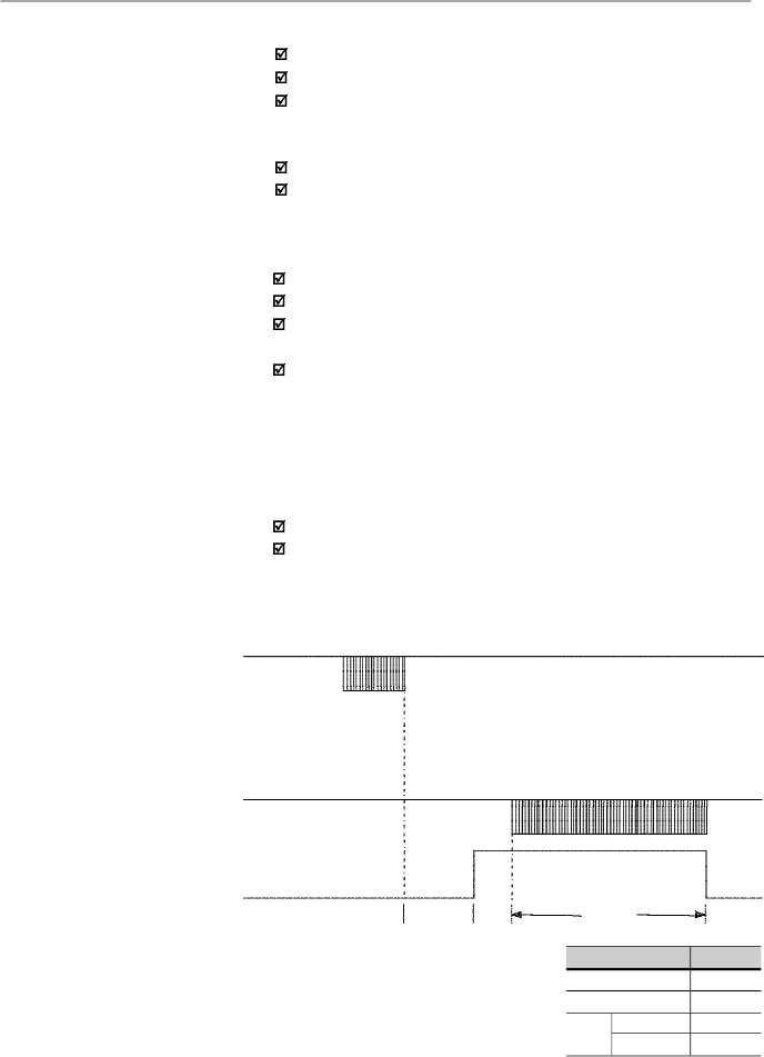
186
CHAPTER 8 - CFW-08 OPTIONS AND ACCESSORIES
They act as follows:
Theydo not disable the inverter;
Theydo not disable the fault relay;
They inform in the word of logical status (V02).
Fault types:
E22: longitudinal parity fault (BCC);
E24: parametrization fault (when some of the situations
indicated in table 4.1 occur (incompatibility between
parameters) or when there is a parameter change attempt
that can not be changed with the motor running).
E25: variable or parameter not existing;
E26: expected values out of allowed limits;
E27: writing attempt in a read only variable or logical
command disabled;
E28: serial interface watchdog timeout error.
Note:
If a parity fault is detected during inverter data reception, the
message will be ignored. The same happens when syntax
errors occur.
Ex.:
Code values different from the numbers 0 to 9;
Separation character different from “ = “, etc.
8.24.5.4
Errors Related to
the Serial
Communication
8.24.6
Time for Read/Write
of Messages
MASTER
Tx: (data)
RSND (request to send)
INVERTER
TxD:
(data)
t
proc
t
di
t
txi
Times (ms)
T
proc
T
di
T
txi
reading
writing
Typical
10
2
15
3
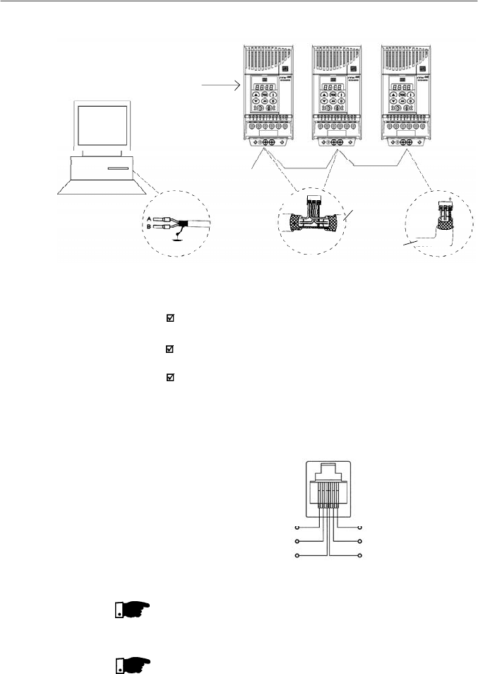
187
CHAPTER 8 - CFW-08 OPTIONS AND ACCESSORIES
Figure 8.32
- CFW-08 network connection through RS-485 serial interface
Network
Master
(PC, PLC)
RS-485
CFW-08
Cable
Shielding
A B
RS-485
XC29
A B
RS-485
XC29
CFW-08
CFW-08
KRS-485-CFW08
NOTE!
The wiring of the RS-232 must be laid separately from the
power cables and the control wiring in 110 V/220 V.
NOTE!
You can not use RS-232 and RS-485 simultaneously.
6
5
4
1
2
3
TX
0 V
RX
+5 V
RTS
0 V
Figure 8.33
- Description of the XC8 (RJ-6) connector
Notes:
Line termination: connect the termination resistors at the
ends of the line.
Grounding of the cable shield: connect the shielding to the
equipment frame (suitable grounding);
Recommended cable: for balanced shielding.
Ex.:AFS series, manufacturer KMP.
Figure below shows the pin position of the XC8 connector of
the KCS-CFW08-S module.
8.24.7
Physical
Connection
RS-232 and RS-485
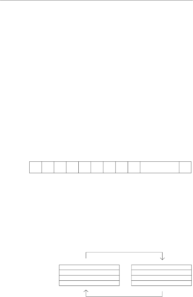
188
CHAPTER 8 - CFW-08 OPTIONS AND ACCESSORIES
8.25
MODBUS-RTU
Modbusprotocol has been developed 1979 firstly. Currentlyit
isa wide diffused openprotocol,used byseveral manufacturers
in different equipment. The Modbus-RTU communication of
the do CFW-08 has been developed by considering two
documents:
1.
MODBUS Protocol Reference Guide Rev. J, MODICON,
June 1996.
2.
MODBUS Application Protocol Specification,
MODBUS.ORG, may 8th 2002.
In these documents are defined the format of the messages
usedbythe elements that are partof the Modbus network, the
services (orfunctions) that can be made available via network,
and also how these elements exchange the data on the
network.
8.25.1.1
Transmission
Modes
Two transmission modes are defined in the protocol definition:
ASCII and RTU. The transmission modes define the form how
the message bytes are transmitted. It is not permitted to use
the two transmission modes on the same network.
In the RTU mode each transmitted word has one start bit, eight
data bits, 1 paritybit (optional) and 1 stop bit (2 stop bits, if no
parity bit is used). Thus the bit sequence for the transmission
of 1 byte is as follows:
8.25.1
Introduction to
Modbus-RTU Protocol
Master Query Message
Address (1 byte)
Function Code (1 byte)
Data (n bytes)
CRC (2 bytes)
Address (1 byte)
Function Code (1 byte)
Data (n bytes)
CRC (2 bytes)
SlaveAnswer Message
8.25.1.2
Message Structure in
RTU Mode
The Modbus RTU network operates in Master-Slave system
and it can consist of up to 247 slaves butonly one Master. The
master always initiates the communication with a question to
a slave and the slave answers the question. Both messages
(question and answer) have the same structure: Address,
Function Code, Data and CRC. Depending on what is being
requested, only the data field has variable length.
Figure 8.34
- Message structure
Start
B0
B1
B2
B3
B4
B5
B6
B7
Parity or Stop
Stop
In the RTU mode, each data byte is transmitted as being a
single word with its value directlyin hexadecimal.The CFW-08
uses only this transmission mode, not having therefore,
communication in ASCII mode.

189
CHAPTER 8 - CFW-08 OPTIONS AND ACCESSORIES
Address:
The master initiates the communication by sending one byte
with the address of the slave to which the message is
addressed. The slave initiates the message with its own
address. The master can also send a message destined to
address 0 (zero), which means that the message is destined
to all network slaves (broadcast). In this case no slave will
answer to the master.
Function code:
This field contains an only byte, where the master specifies
the type of service orthe function requested tothe slave(read,
write, etc.).According to the protocol, each function is used to
access a specific data type. In the CFW-08 all data are
available as holding type registers (referenced from the
address 40000 or ‘4x’). Besides these registers, the inverter
status (enabled/disabled, with error/no error, etc) and the
command for the inverter (run/stop, run FWD/REV, etc.) can
also be accessed through the coils read/write functions orthe
internal bits (referenced from the address 00000 or ‘0x’ on).
Data field:
This field has variable length. The format and the content of
this field depend on the used function and transmitted values.
This field and the respective functions are described in item
8.25.3.
CRC:
The last part of the message is the field for checking the
transmission errors. The used method is the CRC-16 (Cycling
RedundancyCheck). This field is formed by two bytes, where
the least significant byte (CRC-) is transmitted first and only
then the most significant byte is transmitted (CRC+).
CRC calculation is started by loading a 16-bit variable
(mentioned from nowon as CRC variable) with FFFFh value.
Then following steps are executed with the following routine:
1.
The first message byte (only the data bits - the start bit,
paritybit and stop bit are not used) is submitted to the XOR
logic (OR exclusive) with the 8 least significant bits of the
CRC variable, returning the result to the CRC variable,
2.
Then the CRC variable is displaced one position to the right,
in the direction of the least significant bit and the position
of the most significant bit is filled out with zero 0 (zero).
3.
After this displacement, the flag bit (bit that has been
displaced out the CRC variable) is analyzed, by considering
the following:
If the bit value is 0 (zero), no change is made.
If the bit value is 1, the CRC variable content is submitted
to XOR logic with a constantA001h value and the value
is returned to the CRC variable.

190
CHAPTER 8 - CFW-08 OPTIONS AND ACCESSORIES
Figure 8.35
- Times required during the communication of a message
T
11 bits
= Time to transmit one word of the message.
T
entre bytes
= Time between bytes (can notbe longer thanT
3,5x
).
T
3,5x
= Minimum interval to indicate the begin and the
end of the message (3,5 x T
11bits
).
Signal
Time
T
11 bits
T
3,5 x
T
between bytes
T
3,5 x
Message
Communication
T
11 bits
T
3,5x
9600 bits/s
1.146 ms
4.010 ms
19200 bits/s
573
s
2.005 ms
38400 bits/s
285
s
1.003 ms
4.
Repeat steps 2 and 3 until the eight displacements have
been realized.
5.
Repeat the steps 1 to 4, by using the next byte message
until the whole message have been processed.
The end content of the CRC variable is the value of the CRC
field that is transmitted at the end of the message. The least
significant part is transmitted first (CRC), only then the most
significant part (CRC+) is transmitted.
Times between messages:
In the RTU mode there is no specific character thatindicates
thebeginning or the end of a message.Thus the onlyindication
for the beginning or the end of a new message is the data
transmission absence in the network by a minimum time of
3.5 times the time required for transmission of one data word
(11 bits). Thus if a message is initiated after elapsing of the
minimum time required without transmission, the network
elements assume that the received character represents the
beginning of a new message. In similar mode, after this time
has elapsed, the network elements will assume that the
message has been ended.
If during the transmission of a message, the time between
the bytes is longer than this minimum required time, the
message will be considered invalid, since the inverter will
discard the already received bytes and will mount a new
message with the bytes that are being transmitted.
The table below shows the time for three different
communication rates.
Table 8.10
- Times required during the communication of a message

191
CHAPTER 8 - CFW-08 OPTIONS AND ACCESSORIES
8.25.2.2
Inverter
Configuration in
the Modbus-RTU
Network
8.25.2
Operation of the
CFW-08 in the
Modbus-RTU
Network
The CFW-08 frequency inverters operate as slaves of the
Modbus-RTU network. The communication initiates with the
master of the Modbus-RTU network requesting a service for a
network address. When the inverter is configured to the
corresponding address, it processes the question and
answers to the master as requested.
8.25.2.1
RS-232 and
RS-485 Interface
Description
The CFW-08 frequency inverters use a serial interface for the
communication with the Modbus-RTU network. There are two
ways to perform the connection between the network master
and the CFW-08:
RS-232:
The interface is used for the point to point connection
(between a single slave and the master).
Maximum
distance: 10 meters (32.8 ft).
Signal levels according to EIA STANDARD RS-232C.
Three wires: transmission (TX), reception (RX) and return
(0 V).
The RS-232 module (KCS-CFW08) must be used (refer to
item 8.11).
RS-485:
This interface is used for multipoint connection (several
slaves and the master).
Maximum distance: 1000 meters (use of shielded cables).
Signal levels according to EIASTANDARD RS-485.
Mustbe used with the module RS-485 (KRS-485-CFW08),
refer to item 8.13.
Note:
for connection, refer to item 8.24.7.
To ensure a correct communication in the network, you must
configure the inverter address in the network as well as the
transfer rate and the existing parity type, besides the correct
physical connection.
Inverter address in the network:
The inverter address is defined through the parameterP308.
If the serial communication type (P312) has been configured
to Modbus- RTU, you may select the addresses from 1 to
247.
Each slave shall have a different address.
The master does not have address.
The slave address must be known, even when connection
is made point to point.

192
CHAPTER 8 - CFW-08 OPTIONS AND ACCESSORIES
8.25.2.3
Access to the
Inverter Data
All parameters and available basic variables for the CFW-08
can be accessed through the network:
Parameters: are those set in the inverter and that can be
displayed and changed throughthe HMI (Human-Machine
Interface) (refer to item I - Parameters).
Basic Variables: are the internal inverter variables that can
be accessed only through serial interface. For instance,
through these basic variables you can change the speed
reference, read the inverter status, enable or disable the
inverter, etc (refer to item 8.24.5.1 - Basic Variables).
Register: nomenclature used to represent both parameters
and basic variables during data transfer.
Internal Bits: bits that are accessed only through the serial
interface and that are used for inverter status controlling
and monitoring.
Item 8.24.3.2 defines the resolution of the parameters and
variables transmitted via serial interface.
Available functions and response times:
In the Modbus RTU protocol specification is defined the
functions used for accessing different types of registers
described in the specification. In the CFW-08 both parameters
and basic variables are defined as being holding type registers
(referenced as 4x). In addition to these registers, it is also
possible to access the internal controlling and monitoring bits
directly (referenced as 0x).
Following services (or functions) are available in the CFW-08
frequencyinverter for accessing these registers and bits:
Read Coils
Description: reading of internal register blocks or coils.
Function code: 01.
Broadcast: not supported
Response time: 10 to 20 ms.
Read Holding Registers
Description: reading of register blocks of holding type.
Function code: 03.
Broadcast: not supported
Response time: 10 to 20 ms.
Write Single Coil
Description: writing in a single internal bit or coil.
Function code: 05.
Broadcast: supported.
Response time: 10 to 20 ms.
Transmission rate and parity:
Both configurations are defined by parameter P312.
Baud rates: 9600, 19200 or 38400 bits/s.
Parity: none, odd parity or even parity.
All slaves and even the network master must use the same
baud rate and parity.

193
CHAPTER 8 - CFW-08 OPTIONS AND ACCESSORIES
Parameters
...
...
...
...
...
...
Table 8.11
- Parameters addressing
Write Single Register
Description: writing in a single register of holding type.
Function code: 06.
Broadcast: supported
Response time: 10 to 50 ms.
Write Multiple Coils
Description: writing in internal bit blocks or coils.
Function code: 15.
Broadcast: supported
Response time: 10 to 20 ms.
Write Multiple Registers
Description: writing in register blocks of holding type.
Function code: 16.
Broadcast: supported
Response time: 10 to 50 ms for each written register.
Read Device Identification
Description: Identification of the inverter model.
Function code: 43.
Broadcast: not supported.
Response time: 10 to 20 ms.
Note:
the Modbus RTU network slaves are addressed from 1
to 247.
Master uses address 0 to send messages that are
common to all slaves (broadcast).
Data addressing and offset:
The CFW-08 data addressing is realized with an offset equal
to zero, that means that the address number is equal to the
register number. The parameters are available from address
0 (zero) on, whilst the basic variables are available from
address 5000 on. In same way, the status bits are made
available from address 0 (zero) on and the control bits are
made available from address 100 on.
Table below shows the addressing of bits, parameters and
basic variables:
P000
P001
P100
Parameter Number
Modbus Address
Decimal
Hexadecimal
0
1
100
0000h
0001h
0064h

194
CHAPTER 8 - CFW-08 OPTIONS AND ACCESSORIES
Note:
all registers (parameters and basic variables) are
considered as holding type registers, referenced from 40000
or 4x, whilst the bits are referenced from 0000 or 0x.
The status bits have the same functions of the bits 8 to 15 of
the logic status (basic variable 2). These bits are available
onlyfor read, thus anyattempt to write command returns error
status to the master.
Commands Bits
Modbus Address
Decimal
Hexadecimal
Bit 100
100
64h
Bit 101
101
65h
Bit 107
107
6Bh
Bit Number
...
...
...
Table 8.14
- Command bits addressing
Basic Variables
Modbus Address
Decimal
Hexadecimal
V00
5000
1388h
V01
5001
1389h
V05
5005
138Dh
Number of the
Basic Variable
...
...
...
Table 8.12
- Basic variables addressing
Status Bits
Modbus Address
Decimal
Hexadecimal
Bit 0
00
00h
Bit 1
01
01h
Bit 7
07
07h
Bit Number
...
...
...
Table 8.13
- Status bits addressing
Bit Number
Bit 0
Bit 1
Bit 2
Bit 3
Bit 4
Bit 5
Bit 6
Bit 7
Status Bits
Function
0 = Ramp enabling inactive
1 = Ramp enabling active
0 = General enabling inactive
1 = General enabling active
0 = Counter-clockwise direction of rotation
1 = Clockwise direction of rotation
0 = JOG inactive
1 = JOG active
0 = Local mode
1 = Remote mode
0 = No undervoltage
1 = With undervoltage
Not used
0 = No fault
1 = With fault
Table 8.15
- Status bits signified

195
CHAPTER 8 - CFW-08 OPTIONS AND ACCESSORIES
Bit Number
Bit 100
Bit 101
Bit 102
Bit 103
Bit 104
Bit 105
Bit 106
Bit 107
Command Bits
Function
0 = Ramp disable (stops)
1 = Ramp enable (runs)
0 = General disable
1 = General enable
0 = Counter-clockwise direction of rotation
1 = Clockwise direction of rotation
0 = JOG disable
1 = JOG enable
0 = Goes to local mode
1 = Goes to remote mode
Not used
Not used
0 = It does not reset inverter
1 = It resets inverter
8.25.3
Detailed Function
Description
This section describes in details the functions that are
available in the CFW-08 forthe Modbus RTU communication.
Please note the following during the message preparation:
Values are always transmitted as hexadecimal values.
The address of one data, the data number and the value of
the registers are always represented through 16 bits. Thus
these fields are transmitted by using two bytes (high and
low). To access the bits, and the form to represent one bit
depend on the used function.
The messages, both for enquiry and response, cannot be
longer than 128 bytes.
The maximum number of read or written parameters in a
single telegram cannot be bigger than 8.
The resolution of each parameter or basic variable is as
described in item 8.24.3.2.
8.25.3.1
Function 01 -
Read Coils
It reads the content of an internal group of bits that must
compulsorily in a numerical sequence. This function has the
following structure for the read and response messages (the
values are always hexadecimal,and each field represents one
byte):
Query (Master)
Slave address
Function
Initial bit address (byte high)
Initial bit address (byte low)
Number of bits (byte high)
Number of bits (byte low)
CRC-
CRC+
Response (Slave)
Slave address
Function
Byte Count Field (number of data bytes)
Byte 1
Byte 2
Byte 3
etc
CRC-
CRC+
Table 8.16
- Command bits signified
Table 8.17
- Function 01 structure
The command bits are available to read and write and they
have the same function of the logic command bits 0 to 7 (basic
variable 3), however no requiring the use of the mask. The
basic variable 3 write influences the status of these bits.

196
CHAPTER 8 - CFW-08 OPTIONS AND ACCESSORIES
Each response bit is placed at a position of the data bytes
sent bythe slave. The first byte, from the bits 0 to 7, receives
the first 8 bits from the initial address indicated bythe master.
The other bytes (if the number of the read bits is higher than
8) remain in the same sequence. If the number of the read
bits is not a multiple of 8, the remaining bits of the last byte
should be filled out with 0 (zero).
Example: reading of the status bits for general enable (bit
1) and direction of rotation (bit 2) of the CFW-08 at the
address 1:
Query (Master)
Field
Value
Slave address
01h
Function
01h
Initial bit address (byte high)
00h
Initial bit address (byte low)
01h
Number of bits (byte high)
00h
Number of bits (byte low)
02h
CRC-
ECh
CRC+
0Bh
Response (Slave)
Field
Value
Slave address
01h
Function
01h
Byte Count
01h
Status of the bits 1 and 2
02h
CRC-
D0h
CRC+
49h
8.25.3.2
Function 03 -
Read Holding
Register
It reads the content of a group of registers that must be
compulsorily in a numerical sequence. This function has
following structure for the read and response messages (the
values are always hexadecimal,and each field represents one
byte):
As the number of read bits in the example is smaller than 8,
the slave required only 1 byte for the response. The value of
the byte was 02h,thatas binary value will have the form 0000
0010. As the number of read bits is equal to 2, only the two
less significant bits, that have the value 0 = general disable
and 1 = direction of rotation are of interest. The other bits, as
they did not be requested, are filled out with 0 (zero).
Query (Master)
Slave address
Function
Initial register address (byte high)
Initial register address (byte low)
Number of registers (byte high)
Number of registers (byte low)
CRC-
CRC+
Response (Slave)
Slave address
Function
Byte Count Field
Data 1 (high)
Data 1 (low)
Data 2 (high)
Data 2 (low)
etc to
CRC-
CRC+
Table 8.18
- Message example using function 01
Table 8.19
- Function 03 structure

197
CHAPTER 8 - CFW-08 OPTIONS AND ACCESSORIES
8.25.3.3
Function 05 -
Write Single Coil
This function is used to write a value to a single bit. The bit value
is represented by using two bytes, where FF00h represents
the bit that is equal to 1, and 0000h represents the bit that is
equal to 0 (zero). It has the following structure (the values are
always hexadecimal, and each field represents one byte):
Example: read of the value proportional to the frequency
value (P002) and motor current (P003) of the CFW-08 at
address 1:
Query (Master)
Field
Value
Slave address
01h
Function
03h
Initial register (byte high)
00h
Initial register (byte low)
02h
Number of registers(bytehigh)
00h
Number of registers (byte low)
02h
CRC-
65h
CRC+
CBh
Response (Slave)
Field
Value
Slave address
01h
Function
03h
Byte Count
04h
P002 (high)
09h
P002 (low)
C4h
P003 (high)
02h
P003 (low)
8Ah
CRC-
38h
CRC+
95h
Each register is always formed by two bytes (high and low).
For the example, we have P002 = 09C4h, that in decimal
number is equal to 2500.
As this parameter have a two decimal place indication, the
real read value is 25.00 Hz. In the same way we will have a
current value P003 = 028Ah, that is equal to a 650 decimal.
As the current has two decimal resolution, the read value is
6.50 A.
Query (Master)
Slave address
Function
Bit address (byte high)
Bit address (byte low)
Bit value (byte high)
Bit value (byte low)
CRC-
CRC+
Response (Slave)
Slave address
Function
Bit address (byte high)
Bit address (byte low)
Bit value (byte high)
Bit value (byte low)
CRC-
CRC+
Example: to drive a ramp enable command (bit 100 = 1) of
a CFW-08 at the address 1:
Query (Master)
Field
Value
Slave address
01h
Function
05h
Bit number (high)
00h
Bit number (low)
64h
Bit value (high)
FFh
Bit value (low)
00h
CRC-
CDh
CRC+
E5h
Response (Slave)
Field
Value
Slave address
01h
Function
05h
Bit number (high)
00h
Bit number (low)
64h
Bit value (high)
FFh
Bit value (low)
00h
CRC-
CDh
CRC+
E5h
Table 8.20 -
Message example using function 03
Table 8.21
- Function 05 structure
Table 8.22
- Message example using function 05
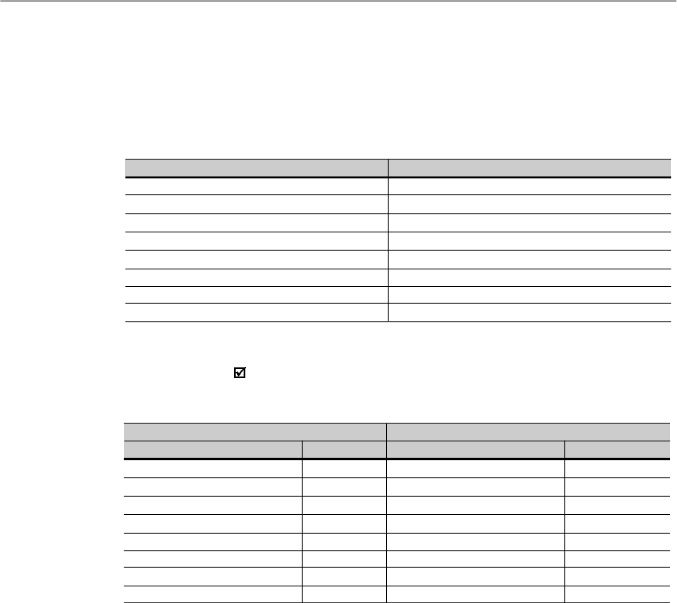
198
CHAPTER 8 - CFW-08 OPTIONS AND ACCESSORIES
8.25.3.5
Function 15 -
Write Multiple
Coils
This function allows writing values for a bit group that mustbe
in numerical sequence. This function can be also used to write
a single bit (the values are always hexadecimal, and each
field represents one byte).
8.25.3.4
Function 06 -
Write Single
Register
This function is used to write a value to a single register. This
function has the following structure (values are always
hexadecimal values, and each field represents one byte):
Query (Master)
Slave address
Function
Register address (byte high)
Register address (byte low)
Value for the register (byte high)
Value for the register (byte low)
CRC-
CRC+
Response (Slave)
Slave address
Function
Register address (byte high)
Register address (byte low)
Value for the register (byte high)
Value for the register (byte low)
CRC-
CRC+
Example:
writeofthespeedreference(basic variable4)equal
to 30.00
H
z
of a CFW-08 at address 1.
Query (Master)
Field
Value
Slave address
01h
Function
06h
Register (high)
13h
Register (low)
8Ch
Value (high)
0Bh
Value (low)
B8h
CRC-
4Bh
CRC+
E7h
Response (Slave)
Field
Value
Slave address
01h
Function
06h
Register (high)
13h
Register (low)
8Ch
Value (high)
0Bh
Value (low)
B8h
CRC-
4Bh
CRC+
E7h
For this function,the slave response will be again anidentical
copyto the request made by the master.As already informed
above, the basic variables are addressed from 5000, thus
the basic variable 4 will be addressed at 5004 (138Ch). The
value for this variable is 30.00 Hz, that is represented by 3000
(0BB8h).
For this function, the slave response is an identical copy of
the query sent by the master.
Table 8.23 -
Function 06 structure
Table 8.24 -
Message example using function 06

199
CHAPTER 8 - CFW-08 OPTIONS AND ACCESSORIES
The value of each bit that is being sent is placed at a position
of the data bytes sent by the master. The first byte, in the bits
0 to 7, receives the 8 first bits by starting from the initial address
indicated by the master. The other bytes (if the number of
inscribed bits is higher than 8) remain in sequence. If the
number of inscribed bits is not a multiple of 8, the remaining
bits of the last byte should be filled in with 0 (zero).
Example: command writing for general enabling (bit100 =
1), general enabling (bit 101 = 1) and CWW-direction of
rotation (bit 102 = 0), for a CFW-08 at address 1:
Query (Master)
Field
Value
Slave address
01h
Function
0Fh
Initial bit (byte high)
00h
Initial bit (byte low)
64h
Number of bits (byte high)
00h
Number of bits (byte low)
03h
Byte Count
01h
Bits Value
03h
CRC-
BEh
CRC+
9Eh
Response (Slave)
Field
Value
Slave address
01h
Function
0Fh
Initial bit (byte high)
00h
Initial bit (byte low)
64h
Number of bits (byte high)
00h
Number of bits (byte low)
03h
CRC-
54h
CRC+
15h
8.25.3.6
Function 16 -
Write Multiple
Registers
This function allows writing values to a register group that must
be in numerical sequence. This function can also be used to
write a single register (the values are always hexadecimal
values and each field represents one byte).
As only three bits are written, the master needed only one
byte to transmit the data. The transmitted values are in the
three less significant bits of the byte that contains the value
for the bits. The other bits of this byte remained with the value
0 (zero).
Query (Master)
Slave address
Function
Initial bit address (byte high)
Initial bit address (byte low)
Number of bits (byte high)
Number of bits (byte low)
Byte Count Field (number of data bytes)
Byte 1
Byte 2
Byte 3
etc to
CRC-
CRC+
Response (Slave)
Slave address
Function
Initial bit address (byte high)
Initial bit address (byte low)
Number of bits (byte high)
Number of bits (byte low)
CRC-
CRC+
Table 8.25 -
Function 15 structure
Table 8.26
- Message example using function 15

200
CHAPTER 8 - CFW-08 OPTIONS AND ACCESSORIES
Query (Master)
Slave address
Function
Initial register address (byte high)
Initial register address (byte low)
Number of registers (byte high)
Number of registers (byte low)
Byte Count Field (number of data bytes)
Data 1 (high)
Data 1 (low)
Data 2 (high)
Data 2 (low)
etc to
CRC-
CRC+
Response (Slave)
Slave address
Function
Initial register address (byte high)
Initial register address (byte low)
Number of registers (byte high)
Number of registers (byte low)
CRC-
CRC+
Example: writing of the acceleration time (P100) = 1,0 s
and deceleration time (P101) = 2.0 s, of a CFW-08 at the
address 20:
Query (Master)
Field
Value
Slave address
14h
Function
10h
Initial register (byte high)
00h
Initial register (byte low)
64h
Number of registers(bytehigh)
00h
Number of registers (byte low)
02h
Byte Count
04h
P100 (high)
00h
P100 (low)
0Ah
P101 (high)
00h
P101 (low)
14h
CRC-
91h
CRC+
75h
Response (Slave)
Field
Value
Slave address
14h
Function
10h
Initial register (byte high)
00h
Initial register (byte low)
64h
Number of registers (byte high)
00h
Number of registers (byte low)
02h
CRC-
02h
CRC+
D2h
As the two parameters have a resolution of a decimal place
for writing of 1.0 and 2.0 seconds,thus the values 10 (000Ah)
and 20 (0014h) should be transmitted.
8.25.3.7
Function 43 -
Read Device
Identification
Auxiliary function that permits reading of the manufacturer,
model and version of the product firmware. It has the following
structure.
Table 8.27 -
Function 16 structure
Table 8.28 -
Message example using function 16

201
CHAPTER 8 - CFW-08 OPTIONS AND ACCESSORIES
Query (Master)
Slave address
Function
MEI Type
Read Code
Object Number
CRC-
CRC+
Response (Slave)
Slave address
Function
MEI Type
Conformity Level
More Follows
Next Object
Number of Objects
Object Code
(*)
Object Length
(*)
Object Value
(*)
CRC-
CRC+
Table 8.29 -
Function 43 structure
This function permits reading of three information
categories: Basic, Regular and Extended and each
category are formed by a group of objects. Each object is
formed bya sequenceofASCII characters For the CFW-08
are onlyavailable basic information formed by threeobjects:
-
Object 00 - VendorName: always ‘WEG’.
-
Object 01 - ProductCode: formed by the product code
(CFW-08), plus the rated inverter current.
-
Object 02 - MajorMinorRevision: it indicates the
inverter firmware version, in ‘VX.XX’ format.
The read code indicates which information categories are
being read and if the objects are accessed individually or
bysequence. In theexample, the inverter supports 01 (basic
information in sequence) and 04 (individual access to the
objects) codes.
The other fields for the CFW-08 have fixed values.
Example: read of basic information in sequence, starting
from object 00, of a CFW-08 at address 1.
(*)
The fields are repeated according to the number of objects.

202
CHAPTER 8 - CFW-08 OPTIONS AND ACCESSORIES
In the example the object value has not been represented as
hexadecimal value, but with corresponding ASCII characters.
For instance, for the object 00, the 'WEG' value has been
transmitted as being three ASCII characters, that as
hexadecimal have the values 57h (W), 45h (E) and 47h (G).
8.25.4
Modbus-RTU
Communication
Errors
Errors can occur during themessage transmission onnetwork,
or in the content of the received messages. Depending on the
error type, inverter may answer or not to the master:
When the mastersends a message toan inverter configured at
determined network address, the inverter will not response if:
Error in the parity bit.
Error in the CRC.
Time out between transmitted bytes (3.5 times the time
required for the transmission of a 11-bit word).
In the case of a successful reception of themessage, the inver-
tercandetectproblemsandsendanerrormessagetothemaster
indicating the problem that has been verified:
Invalid function (error code = 1): the requested function has
not been implemented for theinverter.
Invalid data address (error code = 2): the data address
(register or bit) does not exist.
Data value invalid (error code = 3): this error occurs in the
following conditions:
-
Value is out of permitted range.
-
Writing in data that cannot be changed (onlyread register,
orregisterthat doesnotallowchangingwithenabledinverter
or bits of logic status).
-
Writing in function of the logic command that has not been
enabled via serial interface.
Query (Master)
Field
Value
Slave address
01h
Function
2Bh
MEI Type
0Eh
Read Code
01h
Object Number
00h
CRC-
70h
CRC+
77h
Response (Slave)
Field
Value
Slave address
01h
Function
2Bh
MEI Type
0Eh
Read Code
01h
Conformity Level
51h
More Follows
00h
Next Object
00h
Number of Objects
03h
Object Code
00h
Object Length
03h
Object Value
‘WEG’
Object Code
01h
Object Length
0Ch
Object Value
‘CFW-08 7.0A’
Object Code
02h
Object Length
05h
Object Value
‘V3.77’
CRC-
C7h
CRC+
DEh
Table 8.30
- Message example using function 43
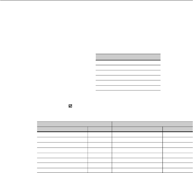
203
CHAPTER 8 - CFW-08 OPTIONS AND ACCESSORIES
Query (Master)
Field
Value
Slave address
01h
Function
06h
Register (high)
00h
Register (low)
32h
Value (high)
00h
Value (low)
00h
CRC-
28h
CRC+
05h
Response (Slave)
Field
Value
Slave address
01h
Function
86h
Error Code
02h
CRC-
C3h
CRC+
A1h
8.25.4.1
Error Messages
When any error occurs in the message content (not during
the data transfer), the slave mustreturn a message indicating
the error type that occurred. The errors that may occur in the
CFW-08 during the message processing are errors relating
to invalid function (code 01), invalid data address (code 02)
and invalid data value (code 03).
The messages sent bythe slave have following structure:
Response (Slave)
Slave address
Function code
(with most significant bit to 1)
Error code
CRC-
CRC+
Master requests to the slave at address 1 to write in the
parameter 50 (inexistent parameter):
Table 8.32
- Message error example
Table 8.31
- Error message structure

204
TECHNICALSPECIFICATIONS
This chapter describes the technical specifications (electrical
and mechanical) of the CFW-08 inverter series.
9.1
POWER DATA
AC Input Specifications:
Voltage: + 10 %, -15 % (with loss of motor efficiency)
Frequency: 50/60 Hz (± 2 Hz)
Phase unbalance:
3 %
Overvoltage: Category III (EN 61010/UL 508C)
Transient voltages according to Category III.
Minimum line impedance: variable according to inverter
model.
Refer to item 8.21.
Power-up:
maximum 10 ON/OFF cycles per hour (1 every 6
minutes).
CHAPTER 9
1.6/
200-240
0.6
1.6
2.4
3.5
5
0.25 HP/
0.18 kW
No
No
Yes
Yes
18
2.6/
200-240
1.0
2.6
3.9
5.7
5
0.5 HP/
0.37 kW
No
No
Yes
Yes
30
4.0/
200-240
1.5
4.0
6.0
8.8
5
1 HP/
0.75 kW
No
No
Yes
Yes
45
7.0/
200-240
2.7
7.0
10.5
8.1
5
2 HP/
1.5 kW
No
No
No
No
80
151 x 75 x 131
[5.94 x 2.95 x 5.16]
Single-phase
Three-
phase
1.6/
200-240
0.6
1.6
2.4
2.0/3.5
(4)
5
0.25 HP/
0.18 kW
No
No
Yes
Yes
18
2.6/
200-240
1.0
2.6
3.9
3.1/5.7
(4)
5
0.5 HP/
0.37 kW
No
No
Yes
Yes
30
4.0/
200-240
1.5
4.0
6.0
4.8/8.8
(4)
5
1 HP/
0.75 kW
No
No
Yes
Yes
44
Single-phase or
three-phase
Model: Current (A) / Voltage (V)
Power (kVA)
(1)
Rated output current (A)
(2)
Max. output current (A)
(3)
Power supply
Rated input current (A)
Switching frequency (kHz)
Maximum motor power
(5)
Dynamic braking
Internal Category C2
RFI filter (optional)
Footprint Category C2 RFI filter
(optional)
External Category C1 RFI filter
(optional)
Watt loss (W)
Dimensions in mm [in]
(Height x Width x Depth)
9.1.1
200-240 V Power Supply
Table 9.1 a)
- Technical information about the inverter models 1.6-2.6-4.0-7.0 A/200-240 V

205
CHAPTER 9 - TECHNICAL SPECIFICATIONS
9.1.2
380-480 V Power Supply
Model: Current (A) / Voltage (V)
Power (kVA)
(1)
Rated output current (A)
(2)
Maximum output current (A)
(3)
Power supply
Rated input current (A)
Switching frequency (kHz)
Maximum motor power
(5)
Dynamic braking
Internal Category C2 RFI filter
(optional)
Footprint Category C2 RFI filter
(optional)
External Category C1 RFI filter
(optional)
Watt loss (W)
Dimensions in mm [in]
(Height x Width x Depth)
1.0/
380-480
0.8
1.0
1.5
1.2
5
0.25 HP /
0.18 kW
No
No
Yes
Yes
17
1.6/
380-480
1.2
1.6
2.4
1.9
5
0.5 HP /
0.37 kW
No
No
Yes
Yes
25
2.6/
380-480
2.0
2.6
3.9
3.1
5
1.5 HP /
1.1 kW
No
No
Yes
Yes
43
4.0/
380-480
3.0
4.0
6.0
4.7
5
2 HP /
1.5 kW
No
No
Yes
Yes
66
2.7/
380-480
2.1
2.7
4.1
3.3
5
1.5 HP /
1.1 kW
Yes
Yes
No
Yes
45
4.3/
380-480
3.3
4.3
6.5
5.2
5
2 HP /
1.5 kW
Yes
Yes
No
Yes
71
6.5/
380-480
5.0
6.5
9.8
7.8
5
3 HP /
2.2 kW
Yes
Yes
No
Yes
109
10/
380-480
7.6
10
15
12
5
5 HP /
3.7 kW
Yes
Yes
No
Yes
168
151 x 75 x 131 [5.94 x 2.95 x 5.16]
200 x 115 x 150 [7.87 x 4.53 x 5.9]
7.3/
200-240
2.8
7.3
11
8.6/16
(4)
5
2 HP/
1.5 kW
Yes
Yes
(Single-
phase)
No
Yes
84
10/
200-240
3.8
10
15
12/22
(4)
5
3 HP/
2.2 kW
Yes
Yes
(Single-
phase)
No
Yes
114
16/
200-240
6.1
16
24
19
5
5 HP/
3.7 kW
Yes
No
No
Yes
183
200 x 115 x 150
[7.87 x 4.53 x 5.9]
Single-phase or
three-phase
Three- phase
Model: Current (A) / Voltage (V)
Power (kVA)
(1)
Rated output current (A)
(2)
Max. output current (A)
(3)
Power supply
Rated input current (A)
Switching frequency (kHz)
Maximum motor power
(5)
Dynamic braking
Internal Category C2
RFI filter (optional)
Footprint Category C2 RFI filter
(optional)
External Category C1 RFI filter
(optional)
Watt loss (W)
Dimensions in mm [in]
(Height x Width x Depth)
22/
200-240
8.4
22
33
24
5
7.5 HP/
5.5 kW
Yes
No
No
Yes
274
203 x
143 x 165
[7.99 x
5.63 x 6.5]
28/
200-240
10.7
28
42
33.6
5
10 HP/
7.5 kW
Yes
No
No
Yes
320
33/
200-240
12.6
33
49.5
40
5
12.5 HP/
9.2 kW
Yes
No
No
Yes
380
290 x 182 x 196
[11.42 x 7.16 x 7.72]
Three- phase
Table 9.1 b)
- Technical information about the inverter models 7.3-10-16-22-28-33 A/200-240 V
Table 9.2 a)
- Technical information about the inverter models 1.0-1.6-2.6-2.7-4.0-4.3-6.5-10 A/380-480 V
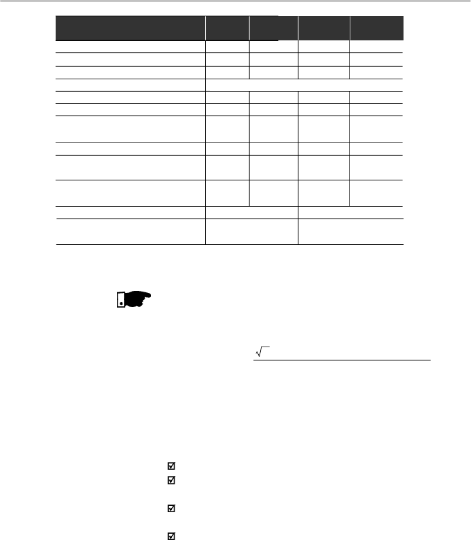
206
CHAPTER 9 - TECHNICAL SPECIFICATIONS
NOTE!
(1)
The power rating in kVA is determined by the following
equation:
P(kVA) =
3 . Voltage (Volt) . Current (Amp)
1000
Model: Current (A) / Voltage (V)
Power (kVA)
(1)
Rated output current (A)
(2)
Maximum output current (A)
(3)
Power supply
Rated input current (A)
Switching frequency (kHz)
Maximum motor power
(5)
Dynamic braking
Internal Category C2 RFI filter
(optional)
External Category C1 RFI filter
(optional)
Watt loss (W)
Dimensions in mm [in]
(Height x Width x Depth)
13/
380-480
9.9
13
19.5
15
5
7.5 HP /
5.6 kW
Yes
Yes
Yes
218
16/
380-480
12.2
16
24
19
5
10 HP /
7.5 kW
Yes
Yes
Yes
268
203 x 143 x 165
[7.99 x 5.63 x 6.5]
24/
380-480
18.3
24
36
28.8
5
15 HP/
11 kW
Yes
Yes
Yes
403
30/
380-480
24
30
45
36
5
20 HP/
15 kW
Yes
Yes
Yes
500
Three- phase
290 x 182 x 196
[11.42 x 7.16 x 7.72]
Table 9.2 b)
- Technical information about the inverter models
13-16-24-30 A/380-480 V
Thevalues showninthetablewerecalculatedbyconsidering the
rated inverter current, input voltage of 220 V for the 200-240 V
models and input voltage of 440 V for the 380-480 V models.
(2)
Rated current is valid for the following conditions:
Relative air humidity: 5 % to 90 %, non condensing.
Altitude: 1000 m (
3280.8
ft), up to 4000 m (
13123.3
ft) with
10 %
derating/
1000
m
(3280.8 ft) of the rated current.
Ambient temperature: 0 ºC to 40 ºC (32 ºF to 104 ºF) (up to
50 ºC (122 ºF) with 2 %/ºC derating of the rated current).
The rated current values are valid for the switching
frequencies of 2.5 kHz or 5 kHz (factory setting). For higher
switching frequencies,
10
kHz
and
15
kHz,
consider the
values shownin the description of the parameter P297 (refer
to chapter 6).
(3)
Maximum output current:
Inverter supports an overload of 50 % (maximum output
current = 1.5 x the rated output current) during 1 minute for
each 10 minutes of operation. For higher switching
frequencies, 10 kHz and 15 kHz, consider 1.5 times the
values shown at the description ofthe parameterP297 (refer
to chapter 6).

207
CHAPTER 9 - TECHNICAL SPECIFICATIONS
(4)
Rated input current for single-phase operation.
Note:
the models CFW080016B2024...,
CFW080026B2024..., CFW080040B2024...,
CFW080073B2024 ... and CFW080100B2024 ... can be
operated both with single-phase voltage and three-phase
voltage without output current derating.
(5)
The indicated motorpower ratings are onlyorientative values
for IV-pole
motors and normal duty loads. The precise in-
verter sizing must consider the actual motor nameplate
and application data.

208
CHAPTER 9 - TECHNICAL SPECIFICATIONS
9.2
ELECTRONICS/GENERALDATA
Voltage Source Inverter
V/F Control or Sensorless Vector Control (V.V.C. - Voltage Vector Control)
PWM SVM (Space Vector Modulation)
0 to 300 Hz, resolution of 0.01 Hz
Speed regulation: 1 % of the rated speed
Speed regulation: 0.5 % of the rated speed
CFW-08: 1 isolated input, resolution: 8 bits, linearity error <0,25 %.
(0 to 10) V or (0 to 20) mA or (4 to 20) mA, Impedance: 100 k
(10
to 10) V, 500
(0 to 20) mA or (4 to 20) mA, programmable function
including digital input or PTC input
CFW-08 Plus: 2 isolated inputs, resolution: 8 bits, linearity error
<0,25 %. (0 to 10) V/(-10 to +10) V/(0 to 20) mA or (4 to 20) mA,
Impedance: 100 k
(0 to 10) V/(-10 to +10) V, 500
(0 to 20) mA/
(4 to 20) mA programmable function including digital input or PTC input
4 isolated digital inputs, NPN or PNP logic, programmable functions
Resolution: 8 bits, programmable functions
CFW-08 Plus: 1
isolated output
,
(
0
to
+10
)
V,
or (0 to 20) mA or
(4 to 20) mA, R
L
10 k
(maximum load)
CFW-08: 1 relaywithreverse contacts, 240 Vac, 0.5A, programmable
functions
CFW-08 Plus: 2 relays, one with NO contact and one with NC
contact. It can be programmed to operate as 1 reverse, 240 Vac,
0.5A, programmable functions
Overcurrent/output short-circuit
Output ground fault
DC link under/overvoltage
Inverter overtemperature
Motor/inverter overload (IxT)
External fault
Programming error
Self-tuning error
Defectiveinverter
8 keys: start, stop, increment, decrement, FWD/REV, JOG,
local/remote and programming
LEDs display: 4 digits with 7 segments
LEDs for FWD/REV and LOCAL/REMOTE indication
It permits access/alteration of all parameters
Display accuracy:
- current: 10 % of the rated current
- speed resolution: 1 rpm
- frequency resolution: 0.01 Hz
Models 22 A, 28 A and 33 A/220-240 V and 13 A, 16 A, 24 A and
30 A/380 V-480 V; other models with KN1-CFW08-M1 and
KN1-CFW08-M2 kits
All models without KN1-CFW08-M1 and KN1-CFW08-M2 kits
Inverters and semicondutors
Power Conversion Equipment
Electronic equipment for use in power installations
Safety requirements for electrical equipment for measurement,
control and laboratory use
EMCproductstandardforadjustablespeedelectricalpowerdrivesystems
CONTROL
METHOD
OUTPUT
FREQUENCY
PERFORMANCE
V/F CONTROL
VECTOR
CONTROL
INPUTS
ANALOG
(Control Board
ECC3)
DIGITAL
OUPUTS
ANALOG
(Control Board
ECC3)
RELAY
SAFETY
PROTECTION
KEYPAD
STANDARD
(HMI)
(HMI-CFW-08-P)
DEGREE OF
NEMA1 / IP20
PROTECTION
PROTECTED CHASSIS/
IP20
STANDARDS
IEC 146
UL 508 C
EN 50178
EN 61010
EN 61800-3
Table 9.3
- General data of the CFW-08 electronics

209
CHAPTER 9 - TECHNICAL SPECIFICATIONS
The inverters are delivered with factory setting to drive WEG
three-phase, IV-pole, IP55 motors, voltage of 220 V for
200-240 V
models or 380 V for 380-480 V models and with
power as indicated in the tables of items 9.1.1 and 9.1.2.
The data of the applied motor must be programmed at P399
to P409 and the value of P409 (stator resistance) obtained
through the Self-Tuning (parameterestimation via P408).
The table below shows the data of WEG standard motors as
a reference.
9.3
WEG STANDARD
IV-POLE MOTOR
DATA
Table 9.4 -
Characteristics of WEG standard IV-pole motors
Power [P404]
(HP)
(kW)
0.16
0.12
0.25
0.18
0.33
0.25
0.5
0.37
0.75
0.55
1.0
0.75
1.5
1.10
2.0
1.50
3.0
2.20
4.0
3.00
5.0
3.70
6.0
4.50
7.5
5.50
10
7.50
12.5
9.20
0.16
0.12
0.25
0.18
0.33
0.25
0.5
0.37
0.75
0.55
1.0
0.75
1.5
1.10
2.0
1.50
3.0
2.20
4.0
3.00
5.0
3.70
6.0
4.50
7.5
5.50
10
7.50
12.5
9.20
15
11
20
15
Frame
63
63
63
71
71
80
80
90S
90L
100L
100L
112M
112M
132S
132M
63
63
63
71
71
80
80
90S
90L
100L
100L
112M
112M
132S
132M
132M
160M
Current
[P401]
(A)
0.85
1.12
1.42
2.07
2.90
3.08
4.78
6.47
8.57
11.6
13.8
16.3
20.0
26.6
33.00
0.49
0.65
0.82
1.20
1.67
1.78
2.76
3.74
4.95
6.70
7.97
9.41
11.49
15.18
18.48
22.7
30.0
Speed
[P402]
(rpm)
1720
1720
1720
1720
1720
1730
1700
1720
1710
1730
1730
1730
1740
1760
1755
1720
1720
1720
1720
1720
1730
1700
1720
1710
1730
1730
1730
1740
1760
1755
1755
1760
Efficiency at
100 % of the
rated power
[P399]
(%)
56.0
64.0
67.0
68.0
71.0
78.0
72.7
80.0
79.3
82.7
84.6
84.2
88.5
89.0
87.7
56.0
64.0
67.0
68.0
71.0
78.0
72.7
80.0
79.3
82.7
84.6
84.2
88.5
89.0
87.7
88.5
90.2
Power factor at
100 % of the
rated power cos
[P407]
0.66
0.66
0.69
0.69
0.70
0.82
0.83
0.76
0.85
0.82
0.83
0.86
0.82
0.84
0.86
0.66
0.66
0.69
0.69
0.70
0.82
0.83
0.76
0.85
0.82
0.83
0.86
0.82
0.84
0.86
0.83
0.83
Stator
resistance
(*)
[P409]
(
)
21.77
14.87
10.63
7.37
3.97
4.13
2.78
1.55
0.99
0.65
0.49
0.38
0.27
0.23
0.16
65.30
44.60
31.90
22.10
11.90
12.40
8.35
4.65
2.97
1.96
1.47
1.15
0.82
0.68
0.47
0.43
0.23
Voltage
[P400]
(V)
220
380
Freq.
[P403]
(Hz)
60
60

210
CHAPTER 9 - TECHNICAL SPECIFICATIONS
(*)
-
The inverter considers the value of the stator resistance as the
motor has been always star-connected, independently of its
connection in the terminal box.
-
The value of the stator resistance is a mean value per phase
consider
ing the motors with temperature rise (
T)of 100
o
C (212 ºF).
Power [P404]
(HP)
(kW)
0
.16
0.12
0.25
0.18
0.33
0.25
0.5
0.37
0.75
0.55
1
0.75
1.5
1.1
2
1.5
3
2.2
4
3
5.5
4
7.5
5.5
10
7.5
0.16
0.12
0.25
0.18
0.33
0.25
0.5
0.37
0.75
0.55
1
0.75
1.5
1.1
2
1.5
3
2.2
4
3
5.5
4
7.5
5.5
10
7.5
15
11
20
15
Frame
63
63
71
71
80
80
90S
90L
100L
100L
112M
132S
132M
63
63
71
71
80
80
90S
90L
100L
100L
112M
132S
132M
160M
160L
Current
[P401]
(A)
0.73
1.05
1.4
1.97
2.48
3.23
4.54
5.81
8.26
11.3
14.2
19.1
25.7
0.42
0.6
0.8
1.13
1.42
1.86
2.61
3.34
4.75
6.47
8.18
11
14.8
22.1
29.1
Efficiency at
100 % of the
rated power
[P399]
(%)
57
58
59
62
68
72
77
79
81.5
82.6
85
86
87
57
58
59
62
68
72
77
79
81.5
82.6
85
86
87
88.5
89.7
Power factor at
100 % of the
rated power cos
[P407]
0.72
0.74
0.76
0.76
0.82
0.81
0.79
0.82
0.82
0.81
0.83
0.84
0.84
0.72
0.74
0.76
0.76
0.82
0.81
0.79
0.82
0.82
0.81
0.83
0.84
0.84
0.81
0.83
Stator
resistance
(*)
[P409]
(
)
30.62
20.31
14.32
7.27
5.78
4.28
2.58
1.69
0.98
0.58
0.43
0.25
0.20
91.85
60.94
42.96
21.81
17.33
12.85
7.73
5.06
2.95
1.75
1.29
0.76
0.61
0.35
0.24
Voltage
[P400]
(V)
230
Freq.
[P403]
(Hz)
400
Speed
[P402]
(rpm)
1375
1360
1310
1320
1410
1395
1420
1410
1410
1400
1440
1450
1455
1375
1360
1310
1320
1410
1395
1420
1410
1410
1400
1440
1450
1455
1455
1460
50
50
Table 9.4 (cont.) -
Characteristics of WEG standard IV-pole motors
