114342 2 Weg Soft Starter Users Manual SSW 06 Inglês User
User Manual: Pump 114342 2 Weg Soft Starter Users Manual
Open the PDF directly: View PDF ![]() .
.
Page Count: 160 [warning: Documents this large are best viewed by clicking the View PDF Link!]
- Summary
- SSW-06 - QUICK PARAMETER REFERENCE
- SAFETY NOTICES
- GENERAL INFORMATION
- INSTALLATION AND CONNECTION
- KEYPAD (HMI) OPERATION
- START-UP
- DETAILED PARAMETER DESCRIPTION
- 6.1 ACCESS AND READ ONLY PARAMETERS - P000 to P099
- 6.2 REGULATION PARAMETERS - P100 to P199
- 6.3 CONFIGURATION PARAMETERS - P200 to P299
- 6.4 - SERIAL COMMUNICATION PARAMETERS – P300 to P399
- 6.5 MOTOR PARAMETERS - P400 to P499
- 6.6 SPECIAL FUNCTION PARAMETERS - P500 to P599
- 6.7 PROTECTIONS PARAMETERS - P600 to P699
- APPLICATIONS AND PROGRAMMING
- DIAGNOSTICS AND TROUBLESHOOTING
- OPTIONS AND ACCESSORIES
- TECHNICAL SPECIFICATIONS

Serie: SSW-06
Software: version 1.3X
0899.5579 E/6
SOFT-STARTER
MANUAL SSW-06
ATTENTION!
It is very important to check if the
Soft-Starter Software is the same as
mentioned above.
12/2006

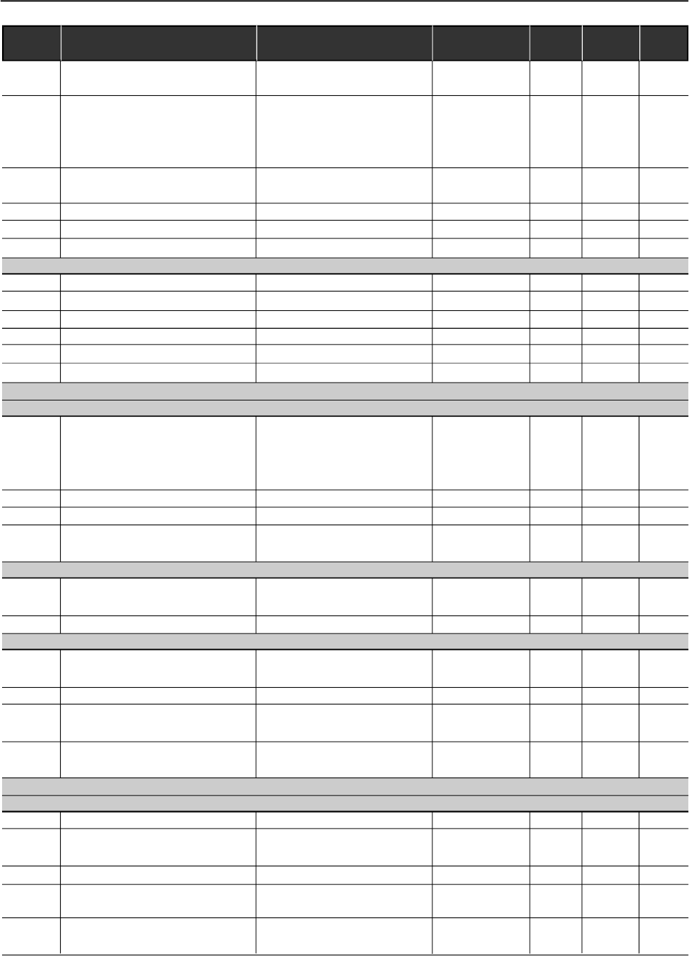
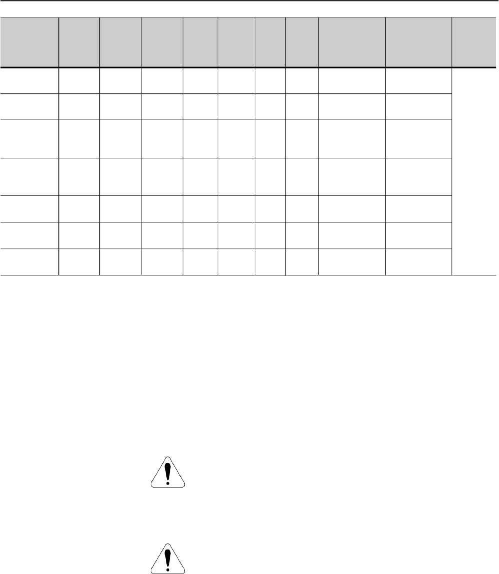
Summary of Revisions
The table below describes the revisions made to this manual.
Revision Description Section
1 First Edition -
2 General Revision -
3 General Revision -
4 New Software Version -
5 Implementation of the following current: 412A, Chap 3
480A, 604A, 670A, 820A, 950A, 1100A and 1400A. and 10
New software version with: braking methods 3, 4, 6
FWD/REV and Jog. and 8
P140 was changed. E73 was eliminated.
E71 and E76 were changed.
6 General Revision -

Summary
Quick Parameter Reference,
Fault and Status Messages
I Parameters ..................................................................................... 09
II Fault Messages.............................................................................. 17
III Other Messages ............................................................................. 17
CHAPTER 1
Safety Notices
1.1 Safety Notices in the Manual.......................................................... 18
1.2 Safety Notice on the Product.......................................................... 18
1.3 Preliminary Recommendations ....................................................... 19
CHAPTER 2
General Information
2.1 About this Manual .......................................................................... 20
2.2 Software Version............................................................................. 20
2.3 About the Soft-Starter SSW-06....................................................... 20
2.4 Soft-Starter SSW-06 Identification .................................................. 23
2.5 Receiving and Storage .................................................................... 25
CHAPTER 3
Installation and Connection
3.1 Mechanical Installation ..................................................................... 26
3.1.1 Environment Conditions .............................................................. 26
3.1.2 Dimensions of the Soft-Starter SSW-06...................................... 26
3.1.3 Mounting Specifications .............................................................. 27
3.1.3.1 Mounting inside a Panel .................................................... 28
3.1.3.2 Mounting on a surface ....................................................... 30
3.2 Electrical Installation......................................................................... 31
3.2.1 Power Terminals ......................................................................... 32
3.2.2 Location of the Power/ Grounding, Control Connections and
Fan Voltage Selection ................................................................ 36
3.2.3 Recommended Power/Grounding Cables ................................... 38
3.2.4AC Input Connection ................................................................... 39
3.2.4.1 Power Supply Capacity ..................................................... 40
3.2.4.2 Recommended Fuses ....................................................... 40
3.2.5 Output Connection ...................................................................... 41
3.2.5.1 StandardThree-Wire Connection (P150=0=Inactive) .......... 41
3.2.5.2 Inside Delta Motor Connection (P150=1=Active) ............... 42
3.2.6 Grounding Connections .............................................................. 43
3.2.7 Fan Connection and Selection of Fan Voltage ............................ 44
3.2.8 Signal and Contro Connections .................................................. 45
3.2.9 RS-232, X2 Serial Communication Connection ........................... 48

Summary
3.2.10 RS-485, XC8 Isolated Serial Communication
Board Connection .................................................................... 48
3.2.11 XC6 Fieldbus Communication Board Connection ...................... 48
3.3 Recommended Set-Ups.................................................................... 48
3.3.1 Recommended Set-ups byKeypad (HMI) Command
with Isolating Contactor. Notes in 3 .3. ....................................... 50
3.3.2 Recommended Set-ups byKeypad (HMI) Command
with Circuit-breaker. Notes in 3.3................................................ 50
3.3.3 Recommended Set-ups with Command via Two-wire
Digital Inputs. Notes in 3.3. ........................................................ 51
3.3.4 Recommended Set-ups with Command via Three-wire
Digital Inputs. Notes in 3.3. ........................................................ 51
3.3.5 Recommended Set-ups with Command via Three-wire
Digital Input and Inside Delta Motor Connection. Notes in 3.3
and 3.2.5.2. ................................................................................ 52
3.3.6 Recommended Set-ups with Command via Three-wire
Digital Input or Serial Communication. Notes in 3.3. .................. 52
3.3.7 Recommended Set-ups with Command via Three-wire
Digital Input or Fieldbus Communication. Notes in 3.3. .............. 53
3.3.8 Recommended Setup with Command via Digital Inputs and
direction of rotation ..................................................................... 53
3.3.9 Recommended Setup with Command via Digital Inputs and
Reverse Braking ......................................................................... 54
3.3.10 Recommended Setup with Command via Digital Inputs and
Optimal Braking ....................................................................... 54
3.3.11 Recommended Setup with Command via Digital Inputs and
DC-Braking ............................................................................... 55
3.3.12 Recommended Setup with Command via Digital Inputs and
External By-pass Contactor ..................................................... 55
3.3.13 Symbols ................................................................................... 56
3.4 European Directives for Electromagnetic Compatibility
Requirements for installation .......................................................... 57
3.4.1 Installation .................................................................................. 57
CHAPTER 4
Keypad (HMI) Operation
4.1 Description of the Keypad (HMI-SSW-06) ..................................... 59
4.2 Use of the Keypad (HMI) ................................................................ 61
4.2.1 Keypad Use for Soft-Starter SSW-06 Operation ......................... 61
4.2.2 HMI Display-Signaling indications............................................... 62
4.2.3 Parameter Viewing and Programming......................................... 63
CHAPTER 5
Start-up
5.1 Power-up Preparation ..................................................................... 65
5.2 Initial Power-up ............................................................................... 66
5.3 Start-up ........................................................................................... 73
5.3.1 Start-up Operation via Keypad (HMI) -

Summary
Type of Control: Voltage Ramp .................................................. 74
CHAPTER 6
Detailed Parameter Description
6.1 Access and Read-Only Parameters - P000 to P099 ...................... 77
6.2 Regulation Parameters - P100 to P199 .......................................... 82
6.3 Configuration Parameters - P200 to P299....................................... 91
6.4 Communication Parameters - P300 to P399 .................................. 104
6.5 Motor Parameters - P400 to P499 .................................................. 106
6.6 Special Function Parameters - P500 to P599 ................................. 107
6.7 Protection Parameters - P600 to P699 ........................................... 113
CHAPTER 7
Applications and Programming
7.1Applications and Programming ......................................................... 121
7.1.1 Starting by Voltage Ramp (P202=0)............................................ 123
7.1.2 Starting by Current Limit (P202=1).............................................. 124
7.1.3 Starting by Current Ramp (P202=4) ............................................ 125
7.1.4 Starting by Current Ramp (P202=4) ............................................ 126
7.1.5 Starting with Pump Control (P202=2) .......................................... 127
7.1.6 Starting with Torque Control (P202=3)......................................... 129
7.1.6.1 Loads with constant torque (P202=3 and P120=1 point) .... 130
7.1.6.2 Loads with high initial torque (P202=3 and P120=3 points) 130
7.1.6.3 Loads with constant torque and S speed curve
(P202=3 and P120=3 points) ............................................. 131
7.1.6.4 Loads with quadratic torque and S speed curve
(P202=3 and P120=2 points) ............................................. 131
7.1.6.5 Loads with quadratic torque and linear speed curve
(P202=3 and P120=3 points) ............................................. 132
7.1.6.6 Loads with quadratic torque and higher initial torque
(P202=3 and P120=3 points) ............................................. 132
7.1.6.7 Hydraulic pump load type (P202=3).................................... 133
7.2 Protections and Programming .......................................................... 136
7.2.1 Thermal Classes ......................................................................... 136
7.2.1.1 Suggestions about thermal class setting ............................ 136
7.2.1.2 Example of how to program the Thermal Class .................. 137
7.2.1.3 Time reduction when changing from cold starting
to hot starting ..................................................................... 138
7.2.1.4 Service Factor .................................................................... 138
CHAPTER 8
Diagnosis and Troubleshooting
8.1 Faults and Possible Causes ............................................................. 139
8.2 Troubleshooting ................................................................................ 143

Summary
8.3 Contacting WEG Telephone/Fax/E-mail for Contact (Servicing) ........ 143
8.4 Preventive Maintenance .................................................................... 144
8.4.1 Cleaning Instructions .................................................................. 145
8.5 Spare Parts List ................................................................................ 145
CHAPTER 9
Options and Accessories
9.1 Remote Keypad (HMI) and Cables.................................................... 146
9.2 RS-485 for the Soft-Starter SSW-06 ................................................. 148
9.2.1 RS-485 Communication Kit for the SSW-06 ............................... 148
9.2.2 Optional MIW-02 Module ............................................................ 149
9.3 Fieldbus Communication Kits ........................................................... 149
9.3.1 Fieldbus DeviceNet Communication Kit for the SSW-06 ............. 149
9.3.2 Fieldbus Profibus DP Communication kit for the SSW-06 .......... 150
CHAPTER 10
Technical Specifications
10.1 Currents and Ratings According to Ul508 ....................................... 151
10.2 Currents and Ratings for IP55, IV Pole Weg Motor ......................... 152
10.3 Power Data ..................................................................................... 153
10.4 Electronics/Programming Data ....................................................... 153
10.5 Mechanical Data............................................................................. 155

9
SSW-06 - QUICK PARAMETER REFERENCE
QUICK PARAMETER REFERENCE, FAULT AND STATUS MESSAGES
Software: V1.3X
Application:
Model:
Serial Number:
Person Responsible:
Date: / / .
I. Parameters
Parameter Description Adjustable Range Factory Unit User´s Page
Setting Setting
P000 Access Parameter 0 to 999 0 - 77
READ ONLY PARAMETERS P001 to P099
P001 Soft-Starter Current 0 to 999.9 - % 78
(%In of the Soft-Starter)
P002 Motor Current (%In of the Motor) 0 to 999.9 -% 78
P003 Motor Current 0 to 9999.9 -A 78
P004 Power Supply Voltage 0 to 999 -V 78
P005 Network Frequency 0 to 99.9 - Hz 78
P006 Soft-Starter Status 0=rdy - ready - - 78
1=Sub - Sub
2=Exx - Error
3=ruP - Run Up
4=FuLL - Full Volt.
5=PASS - By-pass
6=ECO - Reserved
7=rdo - Run Down
8=br - Braking
9=rE - FWD/REV
10=JOG - JOG
11=dly - Delay P630
12=G.di - Gen. Disable
P007 Output Voltage 0 to 999 - V 79
P008 Power Factor 0 to 1.00 - - 79
P009 Motor Torque (% Tn of the Motor) 0 to 999.9 - % 79
P010 Output Power 0 to 6553.5 - kW 79
P011 Apparent Output Power 0 to 6553.5 - kVA 79
P012 Digital Input Status Dl1 to Dl6 0 = Inactive - - 80
1 = Active
P013 Status RL1, RL2 and RL3 0 = Inactive - - 80
1 = Active
P014 Last Fault 03 to 77 - - 81
P015 Second Previous Fault 03 to 77 - - 81
P016 Third Previous Fault 03 to 77 - - 81
P017 Fourth Previous Fault 03 to 77 - - 81
P023 Software Version X.XX - - 81
P030 Current of Phase R 0 to 9999.9 -A 81
P031 Current of Phase S 0 to 9999.9 -A 81
P032 Current of Phase T 0 to 9999.9 -A 81
P033 R-S Line Voltage 0 to 999 -V 81
P034 S-T Line Voltage 0 to 999 -V 81
P035 T-R Line Voltage 0 to 999 -V 81

SSW-06 - QUICK PARAMETER REFERENCE
10
Parameter Description Adjustable Range Factory Unit User´s Page
Setting Setting
P042 Time Powered 0 to 65530 -h 81
P043 Time Enabled 0 to 6553 - h 82
P050 Motor Thermal Protection Status 0 to 250 - % 82
P085 Fieldbus Communication Board Status 0=Off - - 82
1=Board Inactive
2=Board Active and Offline
3=Board Active and Online
REGULATION PARAMETERS P100 TO P199
Voltage Ramp
P101 Initial Voltage (% Un of the motor) 25 to 90 30 % 82
P102 Acceleration Ramp Time 1 to 999 20 s 83
P103 Deceleration Voltage Step 100=Inactive 100=Inactive % 84
(% Un of the motor) 99 to 60
P104 Deceleration Ramp Time 0=Inactive 0=Inactive s 84
1 to 299
P105 End Deceleration Voltage 30 to 55 30 % 84
(% Un of the Motor)
Current Limit
P110 Current Limit 150 to 500 300 % 84
(%In of the Motor current)
P111 Initial Current for the Current Ramp 150 to 500 150 % 85
(% In of the Motor)
P112 Time for the Current Ramp 1 to 99 20 % 85
(% of P102)
Torque Control
P120 (1) Starting Torque Characteristics 1=Constant 1=Constant - 86
2=Linear
3=Quadratic
P121 Initial Starting Torque (% Tn of Motor) 10 to 400 30 % 87
P122 End Starting Torque (% Tn of Motor) 10 to 400 110 % 87
P123 Minimum Starting Torque 10 to 400 27 % 87
(% Tn of the Motor)
P124 Time for the Minimum Start Torque 1 to 99 20 % 87
(% of P102)
P125 (1) Stopping Torque Characteristics 1=Constant 1=Constant - 88
2=Linear
3=Quadratic
P126 End Stop Torque (% Tn of the Motor) 10 to 100 20 % 88
P127 Minimum Stop Torque 10 to 100 50 % 89
(% Tn of the Motor)
P128 Time for the Minimum Stop Torque 1 to 99 50 % 89
(% of P104)
Pump Control
P130 (1) Pump Control 0= Pump I 0= Pump I - 89
1= Pump II
By-pass
P140 (1) External By-pass Contactor 0=Inactive 0=Inactive - 89
1=Active

11
SSW-06 - QUICK PARAMETER REFERENCE
Parameter Description Adjustable Range Factory Unit User´s Page
Setting Setting
Inside Delta
P150 (1) (2) Inside Delta Motor Connection 0=Inactive 0=Inactive - 90
1=Active
CONFIGURATION PARAMETERS P200 to P399
P200 Password 0=Inactive 1=Active - 91
1=Active
P201 (2) Language Selection 0=Portuguese To be defined - 91
1=English by the user
2=Spanish
3=German
P202 (1) Type of the Control 0=Voltage Ramp 0=Voltage Ramp - 91
1=Current limiting
2=Pump Control
3=Torque Control
4=Current Ramp
P204 (1) Load/Save Parameters 0=Not use 0=Not use - 94
1=Not use
2=Not use
3=Reset P043
4=Not use
5=Loads Factory Default
6=Not use
7=Loads User Default 1
8=Loads User Default 2
9=Not use
10=Saves User Default 1
11=Saves User Default 2
P205 Display Default Selection 0=P001 2=P003 - 95
1=P002
2=P003
3=P004
4=P005
5=P006
6=P007
7=P008
P206 Auto-Reset Time 0=Inactive 0=Inactive s 95
1 to 600
P215(1) Keypad Copy Function 0=Inactive 0=Inactive - 96
1=SSW HMI
2=HMI SSW
P218 LCD Display Contrast Adjust. 0 to 150 127 - 97
Local/Remote Definition
P220 (1) Local/Remote Source Selection 0=Always Local 2=HMI(L) - 97
1=Always Remote
2=HMI(L)
3=HMI(R)
4=DI4 to DI6
5=Serial(L)
6=Serial(R)
7=Fieldbus(L)
8=Fieldbus(R)

SSW-06 - QUICK PARAMETER REFERENCE
12
Parameter Description Adjustable Range Factory Unit User´s Page
Setting Setting
P229 (1) Local StatusCommand Selection 0=Keys HMI 0=Keys HMI - 97
1= Digital Inputs DIx
2=Serial
3=Fieldbus
P230 (1) Remote StatusCommand Selection 0=Keys HMI 1=DIx Terminals - 97
1= Digital Inputs DIx
2=Serial
3=Fieldbus
P231 (1) FWD/REVSelection 0=Not used 0=Not used - 98
1=By Contactor
2=JOG Only
Analog Outputs
P251 AO1 (0 to 10)V Output Function 0=Not used 0=Not used - 99
1= Current (%In of the SSW)
2=Input Voltage
(%Un of the SSW)
3=Output voltage
(%Un of the SSW)
4=Power Factor
5=Thermal Protection
6=Power (in W)
7=Power (in VA)
8=Torque (%Tn of Motor)
9=Fieldbus
10=Serial
P252 AO1 Analog Output Gain 0.000 to 9.999 1.000 - 99
P253 AO2 (0 to 20)mA or (4 to 20)mA 0=Not used 0= Not used - 99
Output Function 1= Current (%In of the SSW)
2=Input Voltage
(%Un of the SSW)
3=Output voltage
(%Un of the SSW)
4=Power Factor
5=Thermal Protection
6=Power (in W)
7=Power (in VA)
8=Torque (%Tn of the Motor)
9=Fieldbus
10=Serial
P254 AO2 Analog Output Gain 0.000 to 9.999 1.000 - 99
P255 AO2 Analog Output Selection 0=0 to 20 0=0 to 20 mA 99
1=4 to 20
Digital Inputs
P264 (1) DI2 Digital Input Function 0=Not Used 2= Reset - 100
1=Stop (Three-Wire)
2=Reset
P265 (1) DI3 Digital Input Function 0=Not Used 0=Not used - 100
1=General Enable
2=Reset

13
SSW-06 - QUICK PARAMETER REFERENCE
Parameter Description Adjustable Range Factory Unit User´s Page
Setting Setting
P266 (1) DI4 Digital Input Function 0=Not Used 0=Not Used - 100
1=FWD/REV
2=Local/Remote
3=No External Fault
4=JOG
5=Brake Off
6=Reset
P267 (1) DI5 Digital Input Function 0=Not Used 0=Not used - 101
1=FWD/REV
2=Local/Remote
3=No External Fault
4=JOG
5=Brake Off
6=Reset
P268 (1) DI6 Digital Input Function 0=Not used 0=Not used - 101
1=FWD/REV
2=Local/Remote
3=No external Fault
4=JOG
5=Brake Off
6=Reset
7=Motor Thermistor
Digital Outputs
P277 (1) RL1 Relay Function 0=Not used 1=Running - 102
1=Running
2=Full voltage
3=External By-pass
4=FWD/REV-K1
5=DC-Brake
6= No Fault
7=Fault
8=Fieldbus
9=Serial
P278 (1) RL2 Relay Function 0=Not used 2=Full Voltage - 102
1=Running
2=Full voltage
3=External By-pass
4=FWD/REV-K2
5=DC-Brake
6= No Fault
7=Fault
8=Fieldbus
9=Serial
P279 (1) RL3 Relay Function 0=Inactive 6= No Fault - 102
1=Running
2=Full voltage
3=External By-pass
4= Not used
5=DC-Brake
6= No Fault

SSW-06 - QUICK PARAMETER REFERENCE
14
Parameter Description Adjustable Range Factory Unit User´s Page
Setting Setting
7=Fault
8=Fieldbus
9=Serial
Soft-Starter Data
P295 (1)(2) SSW Rated Current 0=10A 11=312A According to A 103
1=16A 12=365A Soft-Starter
2=23A 13=412A Rated Current
3=30A 14=480A
4=45A 15=604A
5=60A 16=670A
6=85A 17=820A
7=130A 18=954A
8=170A 19=1100A
9=205A 20=1411A
10=255A
P296 (1) (2) Rated Voltage 0=220/575V According to V 103
1=575/690V Soft-Starter
Voltage
PARÂMETROS DE COMUNICAÇÃO SERIAL P300 a P399
P308 (1)(2) Soft-Starter Address on the Serial 1 to 247 1 - 104
Communication Network
P309 (1)(2) Fieldbus Communication 0=Inactive 0=Inactive - 104
Board Enabling 1=Profibus-DP
(1 Inputs and 1 Outputs)
2=Profibus-DP
(4 Inputs and 4 Outputs)
3=Profibus-DP
(7 Inputs and 7 Outputs)
4=DeviceNet
(1 Inputs and 1 Outputs)
5=DeviceNet
(4 Inputs and 4 Outputs)
6=DeviceNet
(7 Inputs and 7 Outputs)
P312 (1)(2) Protocol Type and Serial 1=Modbus-RTU 1=Modbus-RTU 104
Communication Transfer Rate (9600bps, no parity) (9600bps,
2=Modbus-RTU no parity)
(9600bps, odd)
3=Modbus-RTU
(9600bps, even)
4=Modbus-RTU
(19200bps, no parity)
5=Modbus-RTU
(19200bps, odd)
6=Modbus-RTU
(19200bps, even)
7=Modbus-RTU
(38400bps, no parity)
8=Modbus-RTU
(38400bps, odd)
15
SSW-06 - QUICK PARAMETER REFERENCE
Parameter Description Adjustable Range Factory Unit User´s Page
Setting Setting
9=Modbus-RTU
(38400bps, even)
P313 Serial and Fieldbus Communication 0=Inactive 0=Inactive 104
Error Actions (E28, E29 and E30) 1=Disable
2=General Enable
3=Changes to Local
P314(1) Timeout Time for Serial 0 to 999 0= Inactive s 105
Communication Telegram Reception
P315 (1) Read Parameter via Fieldbus 1 0 to 999 0 - 105
P316 (1) Read Parameter via Fieldbus 2 0 to 999 0 - 105
P317 (1) Read Parameter via Fieldbus 3 0 to 999 0 - 105
MOTOR PARAMETERS P400 to P499
P400 (1) Rated Motor Voltage 0 to 999 380 V 106
P401 (1) Rated Motor Current 0.0 to 1500 20 A 106
P403 (1) Rated Motor Speed 400 to 3600 1780 rpm 106
P404 (1) Rated Motor Power 0.1 to 2650 75 kW 106
P405 (1) Motor Power Factor 0 to 1.00 0.89 - 106
P406 (1) Service Factor 0 to 1.50 1.00 - 106
SPECIAL PARAMETERS P500 to P599
Braking
P500 (1) Braking Methods 0=Inactive 0=Inactive - 107
1=Reverse Braking
2=Optimal Braking
3=DC-Braking
P501 Braking Time 1 to 299 10 s 110
P502 Braking Voltage Level 30 to 70 30 % 110
P503 Braking End Detection 0=Inactive 0=Inactive - 110
1=Automatic
JOG
P510 (1) Jog 0=Inactive 0=Inactive - 111
1=Active
P511 Jog Level 10 to 100 30 % 111
Kick Start
P520 (1) Kick Start Torque Pulse 0=Inactive 0=Inactive - 112
(according to P202) 1=Active
P521 Kick Start Pulse Time 0.1 to 2 0.1 s 112
P522 Kick Start Voltage Pulse Level 70 to 90 70 % 112
(% Un of the Motor)
P523 Kick Start Current Pulse Level 300 to 700 500 % 112
(% In of the Motor)
PROTECTION PARAMETERS P600 to P699
Voltage Protection
P600 (1) Undervoltage (% Un of the motor) 0 to 30 20 % 113
P601 (1) Immediate Undervoltage Time 0=Inactive 1 s 113
1 to 99
P602 (1) Overvoltage (% Un of the motor) 0 to 20 15 % 113
P603 (1) Immediate Overvoltage Time 0=Inactive 1 s 113
1 to 99
P604 (1) Voltage Imbalance Between Phases 0 to 30 15 % 114
(% Un of the motor)

SSW-06 - QUICK PARAMETER REFERENCE
16
Parameter Description Adjustable Range Factory Unit User´s Page
Setting Setting
Notes presented on quick parameter description:
(1) This parameter can only be changed with the motor stopped.
(2) This parameter does not change when factory defaults are loaded (P204=5).
P605 (1) Phase Voltage Imbalance Time 0=Inactive 1 s 114
1 to 99
Current Protection
P610 (1) Immediate Undercurrent 0 to 99 20 % 114
(% In of the motor)
P611 (1) Immediate Undercurrent Time 0=Inactive 0=Inactive s 114
1 to 99
P612 (1) Immediate Overcurrent 0 to 99 20 % 114
(% In of the motor)
P613 (1) Immediate Overcurrent Time 0=Inactive 0=Inactive s 114
1 to 99
P614 (1) Current Imbalance between Phases 0 to 30 15 % 115
(% In of the motor)
P615 (1) Current Imbalance Between 0=Inactive 1 s 115
Phase Times 1 to 99
P616 (1) Undercurrent before Closing 0=Inactive 1=Active - 115
of Internal By-pass 1=Active
P617 Motor Overcurrent before By-pass 0=Inactive 1=Active - 115
1=Active
Phase Sequence
P620 (1) RST Phase Current Sequence 0=Inactive 0=Inactive - 115
1=Active
Interval between Starts
P630 Interval of Time after Stop 2 to 999 2 s 115
Motor Thermal Protection
P640 (1) Motor Protection Thermal Class 0=Inactive 5=25 6=30 - 117
of Motor Protection 1=5 6=30
2=10 7=35
3=15 8=40
4=20 9=45
P641 (1) Auto-Reset of thermal Memory 0=Inactive 0=Inactive s 120
1 to 600

17
SSW-06 - QUICK PARAMETER REFERENCE
II. Fault Messages
III. Other Messages
Display Description Page
E03 Undervoltage, Phase Fault or Phase 139
Unbalancing
E04 Overtemperature at the Power Assembly 139
E05 Motor Overload 139
E06 External Fault (DI) 139
E10 Copy Function Fault 139
E15 Motor is not Connected or SCRs in Short-circuit 139
E16 Overvoltage 139
E24 Programming Error 140
E28 Timeout in the Telegram Reception 140
E29 Fieldbus Communication is Inactive 140
E30 Fieldbus Board is Inactive 140
E31 HMI Connection Fault 140
E32 Motor Overtemperature (DI) 140
E41 Self-Diagnosis Fault 140
E62 Start Limiting Time 140
E63 Locked Rotor 140
E65 Undercurrent 141
E66 Overcurrent 141
E67 Inverted Phase Sequence 141
E70 Undervoltage at the Electronics 141
E71 Bypass Contact is Open 141
E72 Overcurrent before By-pass Contact 141
E74 Current Imbalance 141
E75 Frequency of Supply Line 141
out of Permitted Range
E76 Undercurrent before By-pass 141
E77 Bypass Contact is closed or SCRs in Short-circuit 141
For more details see table 8.1 in chapter 8.
Display Description
rdy Soft-Starter is ready to be enabled
ruP Soft-Starter is enabled according to “ramp up”
FuLL Soft-Starter is enabled at “full voltage”
PASS Soft-Starter is enabled with “By-pass”
rdo Soft-Starter is enabled according to “ramp down”
br Soft-Starter is enabled according to “braking”
rE Soft-Starter is enabled according to “reversing”
JOG Soft-Starter is enabled according to “jog”
Sub Soft-Starter under voltage fault
Exx Soft-Starter fault
dly Soft-Starter esperando o tempo após parada "delay"
G.di Soft-Starter com desabilita geral "general disable"
ECO Reserved
18
SAFETY NOTICES
This Manual contains all necessary information for the correct installation
and operation of the SSW-06 Soft-Starter.
The SSW-06 Instruction Manual has been written for qualified personnel
with suitable training or technical qualifications to operate this type of
equipment.
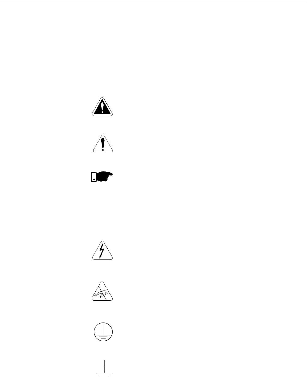
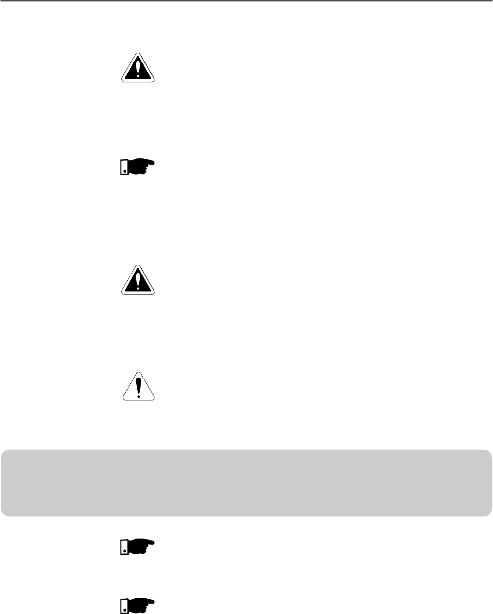
The following Safety Notices will be used in this Manual:
DANGER!
If the recommended Safety Instructions are not strictlyobserved, serious
or fatal injuries of personnel and/or equipment damage can occur.
ATTENTION!
Failure to observe the recommended Safety Procedures can lead to
material damage.
NOTE!
The content of this Manual supplies important information for the correct
understanding of operation and proper performance of the equipment.
1.1 SAFETY NOTICES
IN THE MANUAL
1.2 SAFETY NOTICES ON
THE PRODUCT
The following symbols may be attached to the product, serving as Safety
Notices:
High Voltages
Components are sensitive to electrostatic discharge. Do not touch
them without following proper grounding procedures.
Mandatory connection to ground protection (PE)
Shield connection to ground
CHAPTER 1
CHAPTER 1 - SAFETY NOTICES
19
NOTE!
In this Manual, qualified personnel are defined as people that are trained to:
1. Install, ground, power-up and operate the SSW-06 according to this
Manual and the local required safety procedures;
2. Use of safety equipment according to the local regulations;
3. Administer First Aid Treatment.
DANGER!
Always disconnect the main power supply before touching any electrical
component associated to the SSW-06 Soft-Starter.
High voltages and spinning parts (fans) may be present even after switching
off the power supply. Wait at least 3 minutes for the complete discharge of the
capacitors.
Always connect the equipment frame to the protection earth (PE) in the
appropriate place for this.
ATTENTION!
All electronic boards have components that are sensitive to electrostatic
discharges. Never touch anyof the electrical components or connectors without
following proper grounding procedures. If necessary to do so, touch the properly
grounded metallic frame or use a suitable ground strap.
NOTE!
Soft-Starter SSW-06 can interfere with other electronic equipment. In order to
reduce this interference, adopt the measures recommended in Section 3
“Installation”.
NOTE!
Read this entire manual carefullyand completely before installing or operating
the Soft-Starter SSW-06.
Do not apply high voltage (High Pot) test on Soft-Starter SSW-06!
If this test is necessary, contact the manufacturer
DANGER!
Only qualified personnel should plan or implement the installation, start-up,
operation and maintenance of this equipment. Personnelmustreview this entire
Manual before attempting to install, operate or troubleshoot the SSW-06.
These personnel must follow all safety instructions included in this Manual
and/or defined by local regulations.
Failure to comply with these instructions may result in personnel injury and/or
equipment damage.
1.3 PRELIMINARY
RECOMMENDATIONS

20
GENERAL INFORMATION
This chapter defines the contents and purpose of this manual and
describes the main characteristics of the SSW-06 Soft-Starter.
Identification of the SSW-06, receiving and storage requirements are
also provided.
This Manual is divided into 10 Chapters, providing information to the
user on how to receive, install, start-up and operate the Soft-Starter
SSW-06.
Chapter 1 - Safety Notices;
Chapter 2 - General Information; Receiving and Storing of theSSW-06;
Chapter 3 - Information about Installation and Connection of the
Soft-Starter SSW-06 power and control circuit), how to
install options and recommended drives;
Chapter 4 - Using the Keypad (Human Machine Interface - HMI);
Chapter 5 - Information about running and steps to be followed;
Chapter 6 - Detailed description of all Soft-Starter SSW-06
programming parameters;
Chapter 7- Information and suggestions on how to program the
types of control and protections
Chapter 8 - Information about Diagnostics and Troubleshooting,
cleaning instructions and preventive maintenance;
Chapter 9 - SW-06 Soft-Starter optional devices;
Chapter 10 - Tables and technical information about the power lines
of the Soft-Starter SSW-06;
This Manual provides information for the correct use of the Soft-Starter
SSW-06. Due to the various functions of the Soft-Starter SSW-06 many
different modes of operation are possible.
As the Soft-Starter SSW-06 can be applied in several ways, it is
impossible to describe here all application possibilities, neither can
WEG assume any responsibility when the Soft-Starter SSW-06 is not
used according to this Manual.
No part of this Manual may be reproduced in any form, without written
permission from WEG.
It is important to note the Software Version installed in the Soft-Starter
SSW-06, since it defines thefunctions and the programming parameters
of the Soft-Starter. This Manual refers to the Software version indicated
on the inside cover. For example, the Version 1.0X applies to versions
1.00 to 1.09, where “X” is a variable that willchange due to minor software
revisions.
The Software Version can be read the Parameter P023.
The Soft-Starter SSW-06 is a high performance Drive that permits the
start Control of three-phase AC induction motors. The Soft-Starter
SSW-06 prevents mechanical shocks on the load and current peaks
in the supply line.
Among the main characteristics of this product is its line and connection
fault detection capacity thus enabling the customer to chose the best
way of protecting his the motor, such as:
2.1 ABOUT THIS MANUAL
2.2 SOFTWARE VERSION
2.3 ABOUT THE
SOFT- STARTER
SSW-06
CHAPTER 2

CHAPTER 2 - GENERAL INFORMATION
21
Programmable protections against line undervoltage and
overvoltage, and line phase imbalance;
Thermal class may be programmed up to Class 45 for large motors.
The thermal memory is saved on EEPROM even in case of an
electronic supply fault.
Special functions such as:
Display of the number of hours, running time, supply voltage phase,
motor current per phase, motor current in amperes, motor current
as a% of the Soft-Starter SSW-06 rated current and the rated current
as a % of the motor current, status of the digital inputs and outputs;
Setting sequence after reset to factory default;
Very flexible selection of start/stop control type, enabling the following
selections: Voltage Ramp, Constant Current Limiting or by Ramp,
Pump Control and Constant, Linear or Quadratic Torque Control;
Totally flexible Torque Control providing veryhigh performance for
the most demanding applications;
Possibility of using all digital inputs, digital outputs and analog
outputs as remote PLC via Fieldbus communication;
Possibility of monitoring the power supply voltage measurements in
a PLC network via Fieldbus communication.
Control Hardware:
Keypad, referred to as the Human Machine Interface (HMI) with
Liquid-Crystal Display and easy programming. Fault conditions can
be displayed in several languages.
32Bit Microprocessor calculates the True rms voltage and current;
Measurement of the voltage and current in the three phases;
Isolated digital input for the motor PTC;
Fieldbus boards and RS-485 as options.
Power Hardware:
Compact size;
Power Supply input and output connections:
Models 85A to 820A - Input through the top and output through the
bottom of the SSW-06.Models 950A to 1400A - Input and output
through the bottom.
Easy assembly and maintenance services;
Measurements of heat sink temperature in models 255A to 820A
through two thermostats:One thermostat to switch-on the internal
fans and the other to monitor over-heating.
Soft-Starter SSW-06 can be coupled to the motor by a standard
connection or an inside delta motor connection without requiring
optional devices.
Incorporated By-pass contactor makes the Soft-Starter SSW- 06
(85A to 820A):
More resistant to supply line oscillations after starting;
Save energy that would be dissipated through the thyristors after
the start, thus reducing the number of fans required for control panel
cooling.
CHAPTER 2 - GENERAL INFORMATION
22
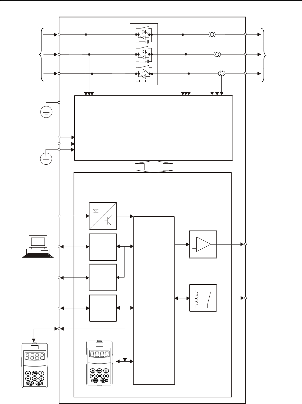
Figure 2.1 - Soft-Starter SSW-06 block diagram
Three-Phase
Power Supply
CONTROL BOARD
Control
Supply
Digital Inputs
Serial
Interface
RS-232
Serial
Interface
(optional)
RS-485
Fieldbus
(optional)
Profibus DP
DeviceNet
Analog Outputs
Digital Outputs
Programmable
Analog Outputs
AO1 and AO2
Programmable
Digital Outputs
RL1... RL3
Programmable
Digital Inputs
DI1...DI6
PC, PLC, MFW,
Super Drive,
ModBUS-RTU
PC,PLC
Three-Phase
Motor
Output
Voltage
Input Voltage Current
Supply
POWERBOARD
HMI
(Remote)
HMI
(1)
(1)
(1)
CPU
PE
PE
(1) Models 950, 1100 and 1400 do not have an internal By-pass contactor.
CHAPTER 2 - GENERAL INFORMATION
23
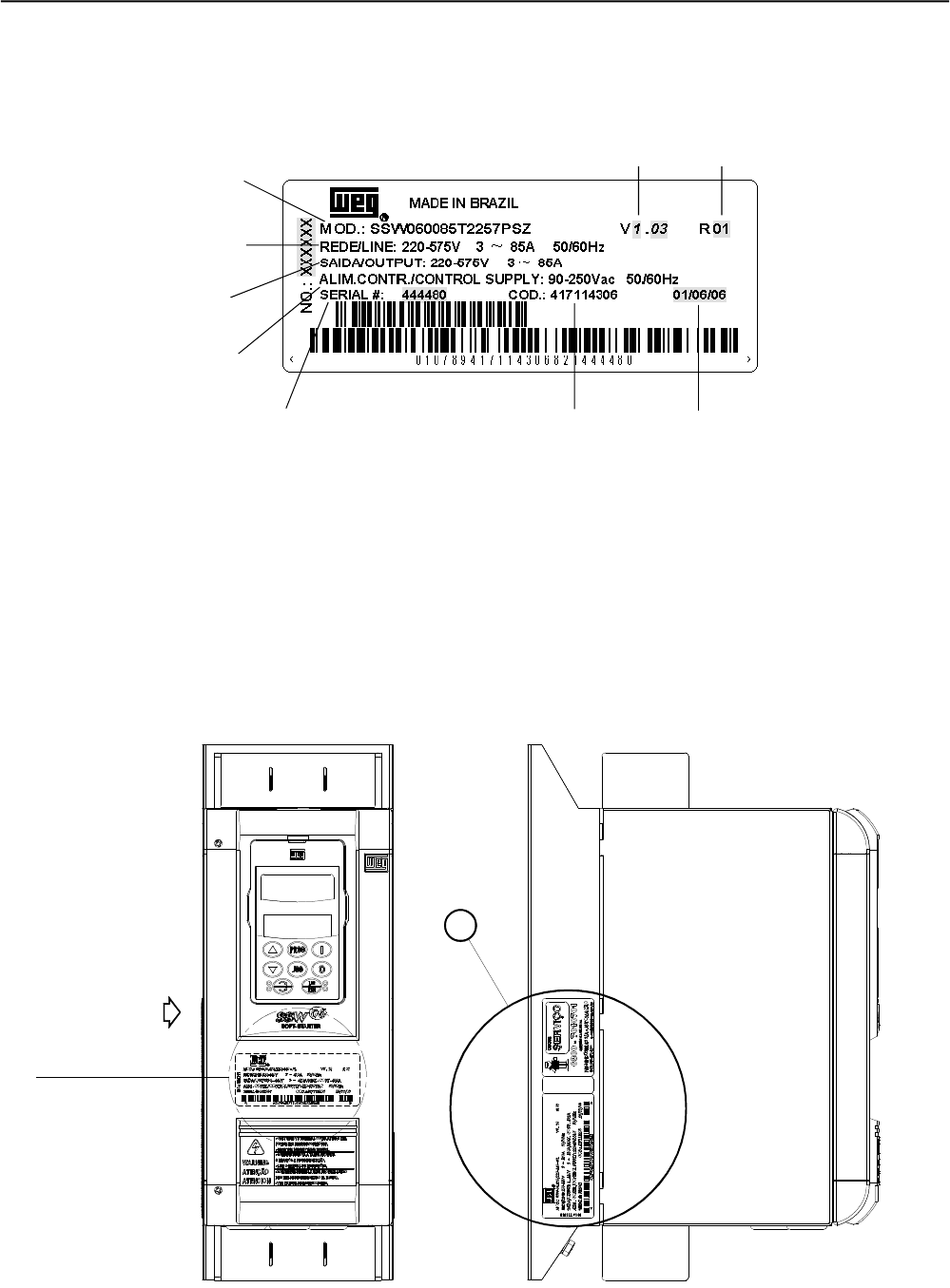
2.4 SOFT-STARTER SSW-06
IDENTIFICATION
Figure 2.2 - Soft-Starter SSW-06 nameplate
Location of Soft-Starter SSW-06 nameplate:
Figure 2.3 - Detail of the Soft-Starter SSW-06 nameplate
VER DETALHE "A"
X
FRONTAL
A
VISTA DE X
SSW-06 Model
Input Data (Voltage, Number of
Phases, Current, Frequency)
Output Data (Voltage, Number
of Phases, Current)
Control Power Supply Data
(Voltage, Frequency)
Serial Number
Software
Version Hardware
Revision
Manufacturing
Date
View Detail A
Identification nameplate
of the SSW-06
(Internal Cover)
FRONT VIEW VIEW X
WEGItem
Number

CHAPTER 2 - GENERAL INFORMATION
24
Rated
Output
Current:
0085=85A
0130=130A
0170=170A
0205=205A
0255=255A
0312=312A
0365=365A
0412=412A
0480=480A
0604=604A
0670=670A
0820=820A
0950=950A
1100=1100A
1400=1400A
Thee-phase
Power
Supply
Power Supply
Voltage:
2257 =
(220 to 575)V
Manual
Language:
P= portuguese
E=English
S=Spanish
G=German
Human-
Machine
Interface
(Keypad):
Blank =
standard
SI= without
keypad
HOW TO SPECIFY THE SSW-06 MODEL:
SSW-06 0023 T 2257 P O _ _ _ _ _ _ Z
Special
Software:
Blank =
standard
S1=Special
Software
Special
Hardware:
Blank =
standard
H1 = 115V
Ventilation
(Model 950A)
H2 = 230V
Ventilation
(Models
950A, 1100A
and 1400A)
Soft-Starter
SSW-06
WEG Series
End of
Code
NOTES!
The option field (S or O) defines if the Soft-Starter SSW-6 is a standard version or if it is equipped with any optional devices. If the standard version is
required, the code ends here. The model number always has the letter Z at the end. For example:
SSW060085T2257ESZ = Standard Soft-Starter SSW-06 with current of 85A and 220V to 575V with Manual in English.
If there are accessories, the spaces must be filled out in the correct sequence until the code ends with the letter zero.
The standard product is defined as described here:
Degree of protection:IP00 from 85A to 1400A
Human-Machine-Interface: HMI-SSW06 (with LCD and LED displays).
Obs.: The communication kits are optional, see chapter 9.
Options:
S=Standard
O=with options

CHAPTER 2 - GENERAL INFORMATION
25
2.5 RECEIVINGAND
STORAGE
The SSW-06 is supplied in packaging according to the model:
-Models 85A to 205A in a cardboard box;
-Models 255A to 365A in a cardboard box over a wooden box;
-Models 412A to 1400A in a wooden box.
The outside of the packing container has a nameplate that is identical
to that on the Soft-Starter SSW-06. Please check if the nameplate data
matches the ordered data.
The models up to 205A must be placed and opened on a table with the
help of two or more people, open the box, remove the foam protection
and remove Soft-Starter SSW-06.
The models up to 205A must be placed and opened on a table with the
help of two or more persons.
Open the box, remove the foam protection and remove Soft-Starter
SSW-06 with the help of two or more persons.
Models greater than 255A must be opened on the floor. Open the box
and,remove the bolts that fasten the Soft-Starter SSW-06 on the pallet.
The Soft-Starter SSW-06 must be handled with a hoist.
Check if:
The Soft-Starter SSW-06 nameplate data matches the purchase
order;
The equipment has not been damaged during transportation. If any
problem is detected, contact the carrier immediately.
If the Soft-Starter SSW-06 is not to be installed immediately, store it
within its original cardboard box in a clean and dry room (Storage
temperatures between - 10°C (14ºF) and 65°C (149ºF)).
26
CHAPTER 3
3.1 MECHANICAL
INSTALLATION
INSTALLATION AND CONNECTION
This chapter describes the electric and mechanic installation procedures
of the SSW-06 Soft-Starters. The orientations and suggestions must
be followed for correct product functioning.
3.1.1 Environment Conditions The location of the Soft-Starter SSW-06 installation is an important
factor to assure good performance and high product reliability.
For proper installation of the SSW-06 Soft-Starter, we make the following
recommendations:
Avoid direct exposure to sunlight, rain, excessive humidity or marine
environment;
Gases or explosive or corrosive liquids;
Excessive vibration, dust or metallic and/or oil particles in the air.
Allowed Environment Conditions:
Temperature: 0ºC to 55ºC (32ºF to 131ºF) – Rated conditions for
models 85A to 820A;
0ºC to 40ºC (32ºF to 104ºF) – Rated conditions for models 950A to
1400A.
2% Current reduction for each degree Celsius above thespecification
in the rated conditions.
RelativeAir Humidity: 5% to 90%, non-condensing.
Maximum Altitude:1000m ( 3,300 ft) - rated conditions.
From 1000m to 4000m (3,300ftto 13,200ft) - with 1% currentreduction
for each 100m (330ft) above 1000m (3,300ft).
Degree of Pollution: 2 (according to UL508).
Water, condensation or conductive dust/particles are not allowed in
the air.
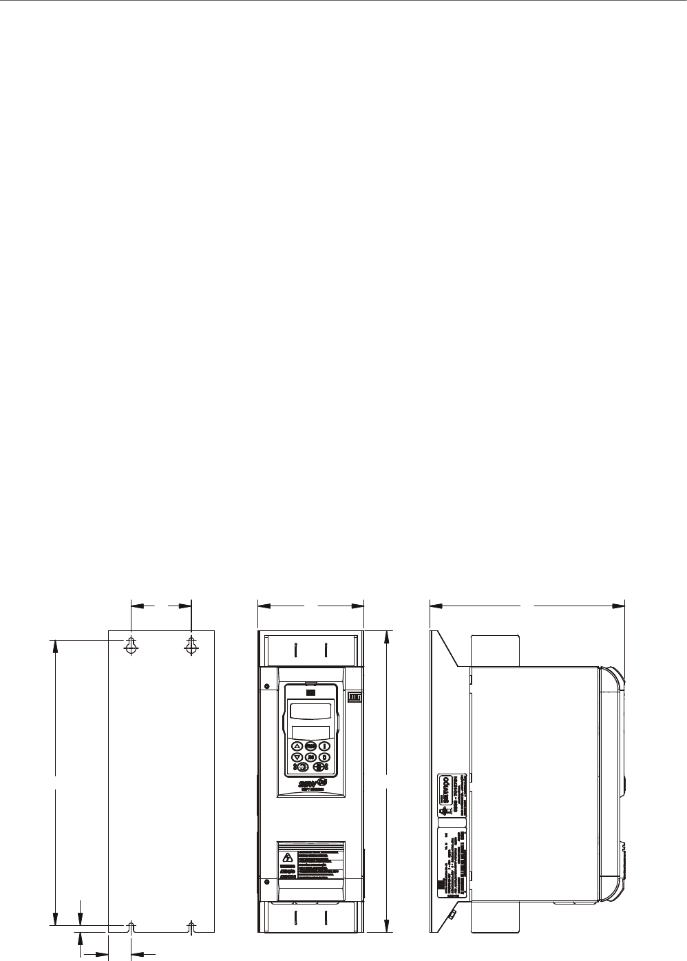
3.1.2 Dimensions of the
Soft-Starter SSW-06
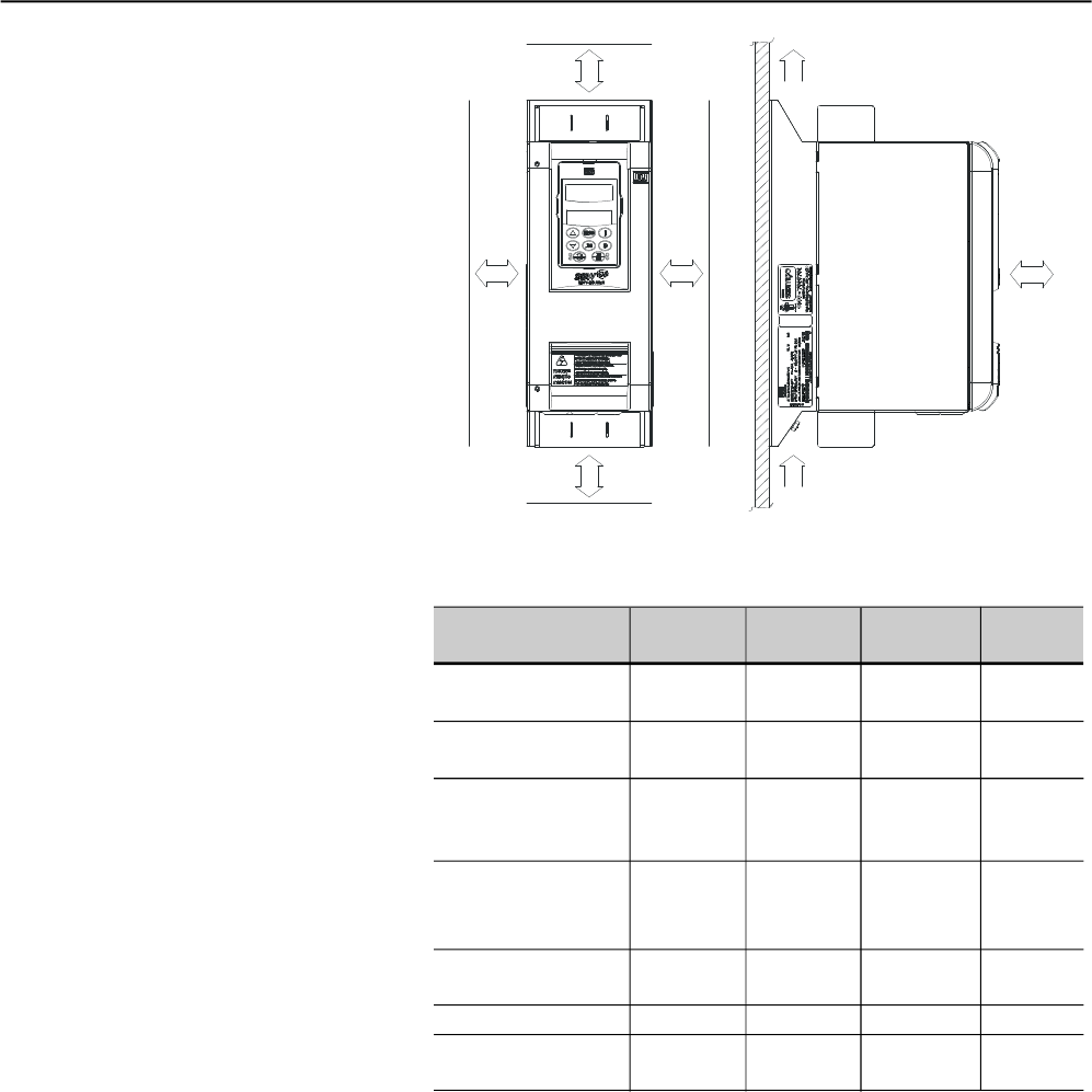
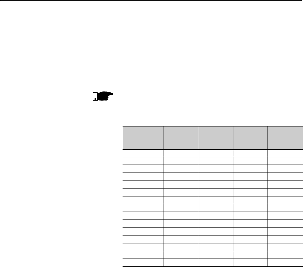
External dimensions and mounting holes follow Figure 3.1 and Table 3.1.
Figure 3.1 - Dimensional Drawings of the Soft-Starter SSW-06
AWD
C
B
D2
H
CHAPTER 3 - INSTALLATIONAND CONNECTION
27
Model
Height Width Depth. A B C D2 Mounting Weight Degree of
H W D mm mm mm mm screw Kg Protection
mm mm mm (in) (in) (in) (in) mm (lb)
(in) (in) (in) (in)
SSW-06.0085 370 132 244 75 350 28.5 8.5 M5 8.5
IP00
SSW-06.0130 (14.57) (5.20) (9.61) (2.95) (13.78) (1.12) (0.33) (1/4") (18.74)
SSW-06.0170 440 223 278 150 425 36.5 5.9 M6 18.5
SSW-06.0205 (17.32) (8.78) (10.94) (5.91) (16.73) (1.44) (0.23) (1/4") (40.79)
SSW-06.0255 550 370 311 200 527.5 84.8 10 M6 39.5
SSW-06.0312 (21.65) (14.57) (12.24) (7.87) (20.77) (3.34) (0.39) (1/4") (87.08)
SSW-06.0365
SSW06.0412 650 369.5 347 200 627.5 84.75 11.25 M6 55.0
SSW06.0480 (25.59) (14.55) (13.67) (7.87) (24.7) (3.33) (0.44) (1/4") (121.27)
SSW06.0604
SSW06.0670 795 540 357.12 250 775 145 10 M8 120.0
SSW06.0820 (31.3) (21.26) (14.06) (9.84) (30.51) (5.71) (0.39) (5/16") (264.60)
SSW06.0950 894.5 568.2 345.15 400 810 84.1 10 M8 107.0
(35.22) (22.37) (13.59) (15.75) (31.89) (3.31) (0.39) (5/16") (235.93)
SSW06.1100 1234.8 685 432.94 500 1110 92.5 15 M8 217.5
SSW06.1400 (48.61) (26.97) (17.04) (19.68) (43.7) (3.64) (0.59) (5/16") (479.59)
Table 3.1 - Installation Data with dimensions in mm (in)
At least the spaces around the soft-starter must be left open for the
installation of the SSW-06 Soft-Starter, according to Figure 3.2, as
follows. The dimensions of each space are described in table 3.2.
Install the Soft-Starter SSW-06 in the vertical position according to the
following recommendations:
1) Install the SSW-06 Soft-Starter on a flat surface;
2) Do not place heat sensitive components on top of the SSW-06 Soft-
Starter;
ATTENTION!
If the Soft-Starters are installed one next to the other, use minimum
distance B.
When a Soft-Starter is installed on top of another, use minimum distance
A+C and avoid to the Soft-Starter above the hot air that comes from the
Soft-Starter below.
ATTENTION!
Foresee independent conduits or electroducts for physicallyseparating
the signal, control and power conductors (see item 3.2, electrical
installation).
3.1.3 Positioning / Fixing
CHAPTER 3 - INSTALLATIONAND CONNECTION
28
Figure 3.2 - Free spaces for cooling
C
A
Y
B
B
Table 3.2 - Recommended free spaces
Air Flow Outlet
Air Flow Inlet
A
mm (in)
150 (5.90)
150 (5.90)
150 (5.90)
150 (5.90)
150 (5.90)
150 (5.90)
150 (5.90)
Model
SSW-06.0085
SSW-06.0130
SSW-06.0170
SSW-06.0205
SSW-06.0255
SSW-06.0312
SSW-06.0365
SSW-06.0412
SSW-06.0480
SSW-06.0604
SSW-06.0670
SSW-06.0820
SSW-06.0950
SSW-06.1100
SSW-06.1400
B
mm (in)
30 (1.18)
30 (1.18)
30 (1.18)
30 (1.18)
30 (1.18)
30 (1.18)
100 (3.93)
C
mm (in)
150 (5.90)
150 (5.90)
150 (5.90)
150 (5.90)
150 (5.90)
150 (5.90)
150 (5.90)
Y
mm (in)
50 (1.96)
50 (1.96)
50 (1.96)
50 (1.96)
50 (1.96)
50 (1.96)
50 (1.96)
When the Soft-Starter SSW-06 are installed in panels or closed metallic
boxes, adequate cooling is required to ensure that the temperature
around the inverter will not exceed the maximum allowed temperature.
See Dissipated Power in the table 3.4.
3.1.3.1 Mounting inside a Panel
CHAPTER 3 - INSTALLATIONAND CONNECTION
29
Use the minimum recommended panel dimensions and its cooling
requirements:
Table 3.3 - Panel Dimensions and Cooling Requirements
Table 3.4 - Power losses for panel fan dimensioning
NOTE!
The fans above are recommended for duties of 10 starts/hour with 3 x In
of the Soft-Starter during 30s.
Power Losses
In the
eletronics Fan Power Total Power losses in
the SCRs in Full
Voltage
Average power
losses-10 starts/h
3xln@30s
Total average power
losses-10 starts/h
3xIn@30s
Model
W W W W W
SSW-06.0085 33 - 0 = By-pass 76.5 109.5
SSW-06.0130 33 - 0 = By-pass 117.0 150.0
SSW-06.0170 33 - 0 = By-pass 153.0 186.0
SSW-06.0205 33 - 0 = By-pass 184.5 217.5
SSW-06.0255 33
58
528mA@110Vac
264mA@220Vac 0 = By-pass 229.5 320.5
SSW-06.0312 33
58
528mA@110Vac
264mA@220Vac 0 = By-pass 280.8 371.8
SSW-06.0365 33
58
528mA@110Vac
264mA@220Vac 0 = By-pass 328.5 419.5
SSW-06.0412 33
58
528mA@110Vac
264mA@220Vac 0 = By-pass 370.8 461.8
SSW-06.0480 33
58
528mA@110Vac
264mA@220Vac 0 = By-pass 432.0 523.0
SSW-06.0604 33
58
528mA@110Vac
264mA@220Vac 0 = By-pass 543.6 634.6
SSW-06.0670 33
87
396mA@110Vac
972mA@220Vac 0 = By-pass 603.0 723.0
SSW-06.0820 33
87
396mA@110Vac
1391mA@220Vac 0 = By-pass 738.0 858.0
SSW-06.0950 33
160
727mA@110Vac
955mA@220Vac 3420 427.5 3898.0
SSW-06.1100 33
210
955mA@220Vac 3960 495.0 4533.0
SSW-06.1400 33 210 955mA@220Vac 5040 630.0 5703.0
Cooling CFM
(m3/min)
-
-
-
-
-
1757.30 (49.80)
1757.30 (49.80)
2648.44 (75.00)
Model
SSW-06.0085
SSW-06.0130
SSW-06.0170
SSW-06.0205
SSW-06.0255
SSW-06.0312
SSW-06.0365
SSW-06.0412
SSW-06.0480
SSW-06.0604
SSW-06.0670
SSW-06.0820
SSW-06.0950
SSW-06.1100
SSW-06.1400
Panel Dimensions
Width Hiegth Depth
mm (in) mm (in) mm (in)
600 1200 400
(23.62) (47.24) (15.75)
600 (23.62) 1600 (63.00) 600 (23.62)
600 2000 600
(23.62) (78.74) (23.62)
600 2000 600
(23.62) (78.74) (23.62)
800 2000 600
(31.50) (78.74) (23.62)
800 (31.50) 2000 (78.74) 600 (23.62)
800 2000 600
(31.50) (78.74) (23.62)
CHAPTER 3 - INSTALLATIONAND CONNECTION
30
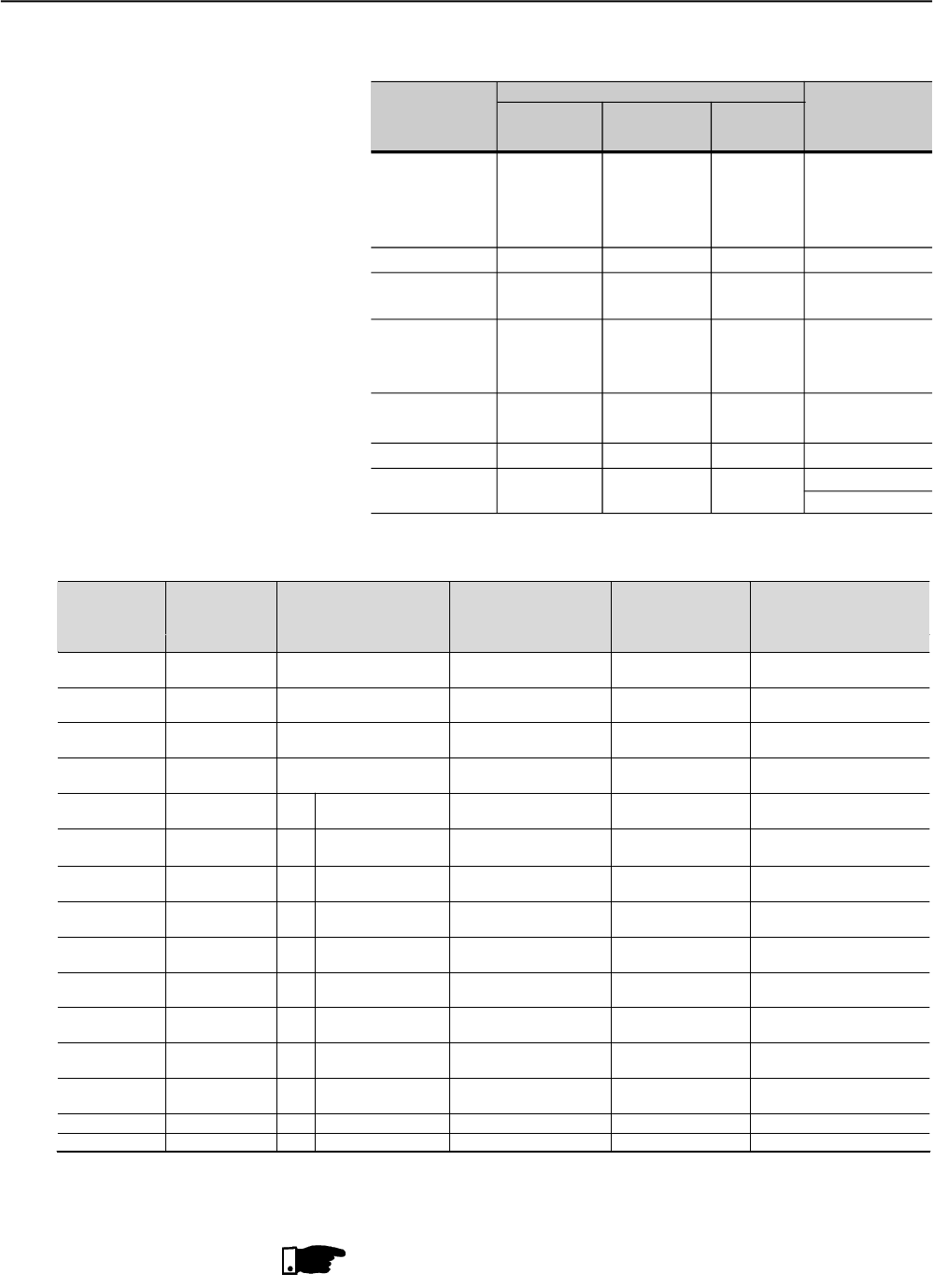
The total power losses can be determined through the equation below:
where:
Pe = power losses at the electronics (W)
tc = working cycle time (s)
Ip = start current (A)
tp = start time (s)
In = current at rated duty (A), with By-pass In=0
tr = rated duty time (Full Voltage) (s)
Ptd = total power losses (W)
Figure 3.3 - Soft-Starter SSW-06 working cycle for
power loss determination
Ptd
tc
trInVtpIpVtcPe
)32.1()32.1()(
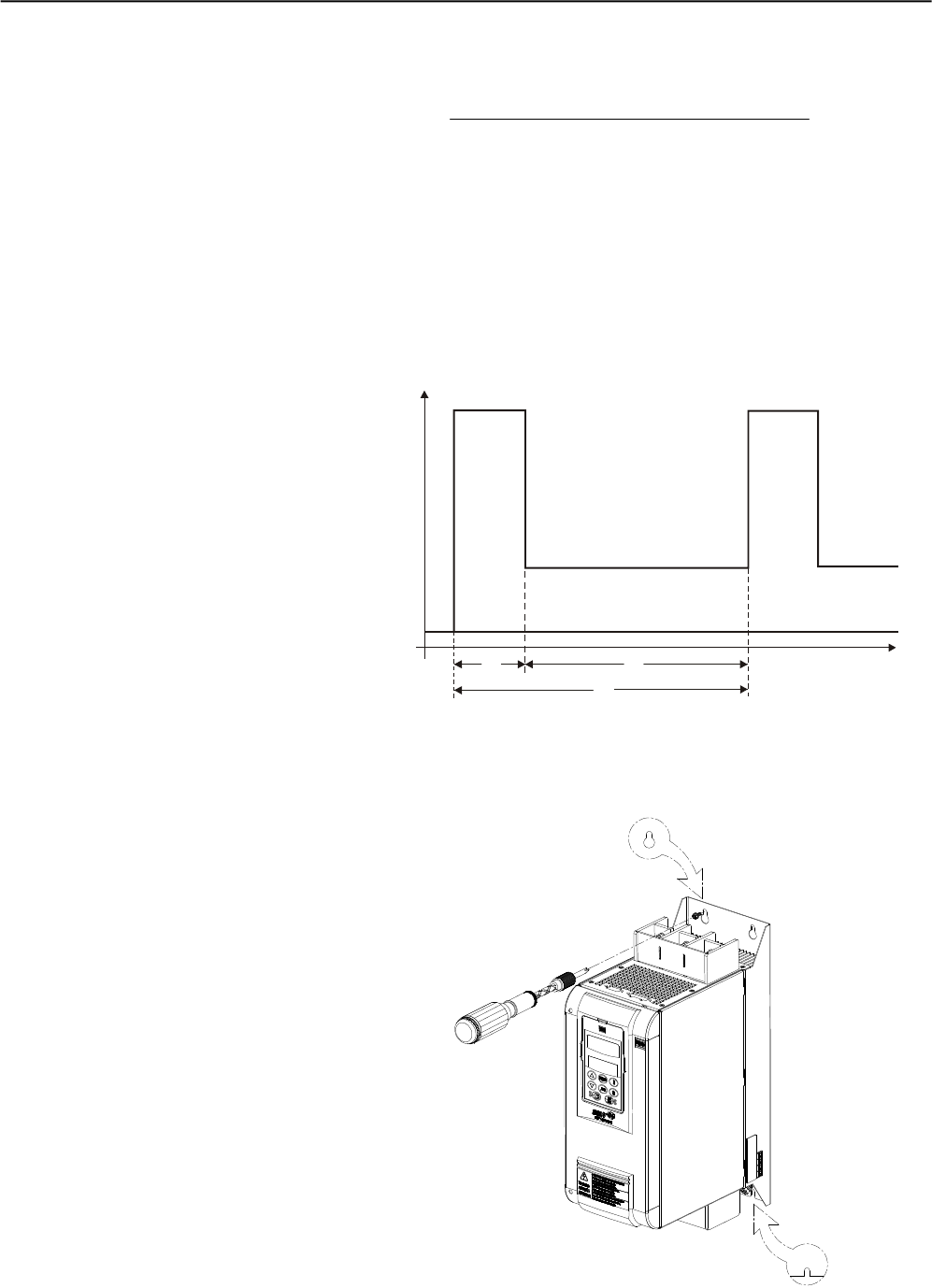
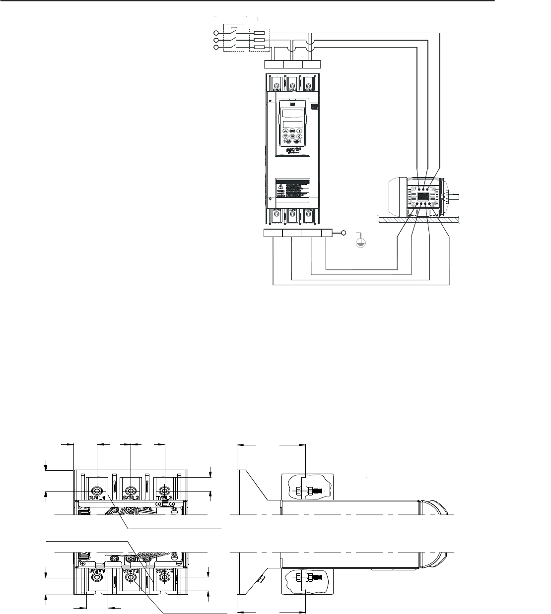
The figure 3.4 shows the installation of the Soft-Starter SSW-06 on a
mounting plate.
3.1.3.2 Mounting on a Surface
Figure 3.4 - Mounting procedures for the SSW-06 on a flat surface
P(W)
I(A) Ip
0tp tr
tc
Pe
In
t(s)
CHAPTER 3 - INSTALLATIONAND CONNECTION
31
First install and partially tighten the mounting bolts, in agreement with
figures 3,1 and 3,4 and table 3.1, then install the Soft- Starter SSW-06
and tighten the mouthing bolts.
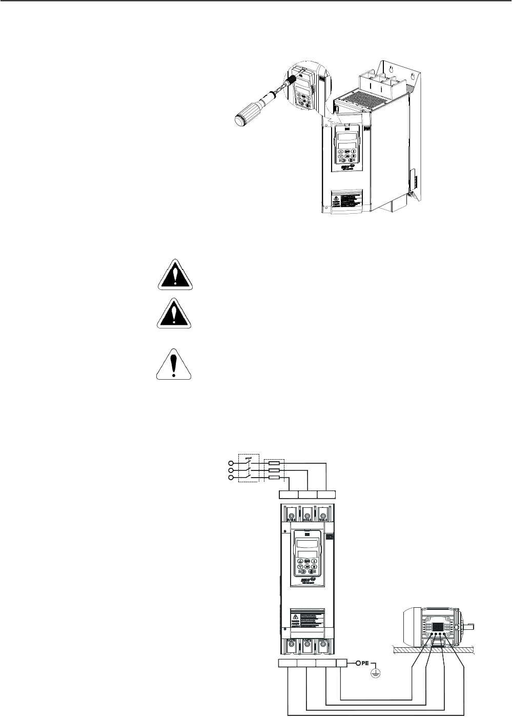
Figure 3.5 - Procedures for HMI removal and front cover
opening of the control connections
3.2 ELECTRICAL
INSTALLATION DANGER!
The Soft-Starter SSW-06 cannot be used as an emergencystop device.
DANGER!
Be sure that the AC input power is disconnected before making any
terminal connections.
ATTENTION!
The information below will be a guide to achieve a proper installation.
Also follow all applicable local standards for electrical installations.
Provide at least a 0.25m (10 in) space between the sensitive equipment
and wiring from the Soft-Starter SSW-06, and the cables between the
Soft-Starter SSW-06 and the motor. Example: PLC, temperaturewiring,
thermocouple cables, etc.
Figure 3.6 - Standard power/grounding connections
R/1L1 S/3L2 T/5L3
Circuit-breaker
Line Fuses
T
S
R
U/2T1 PEV/4T2 W/6T3
CHAPTER 3 - INSTALLATIONAND CONNECTION
32
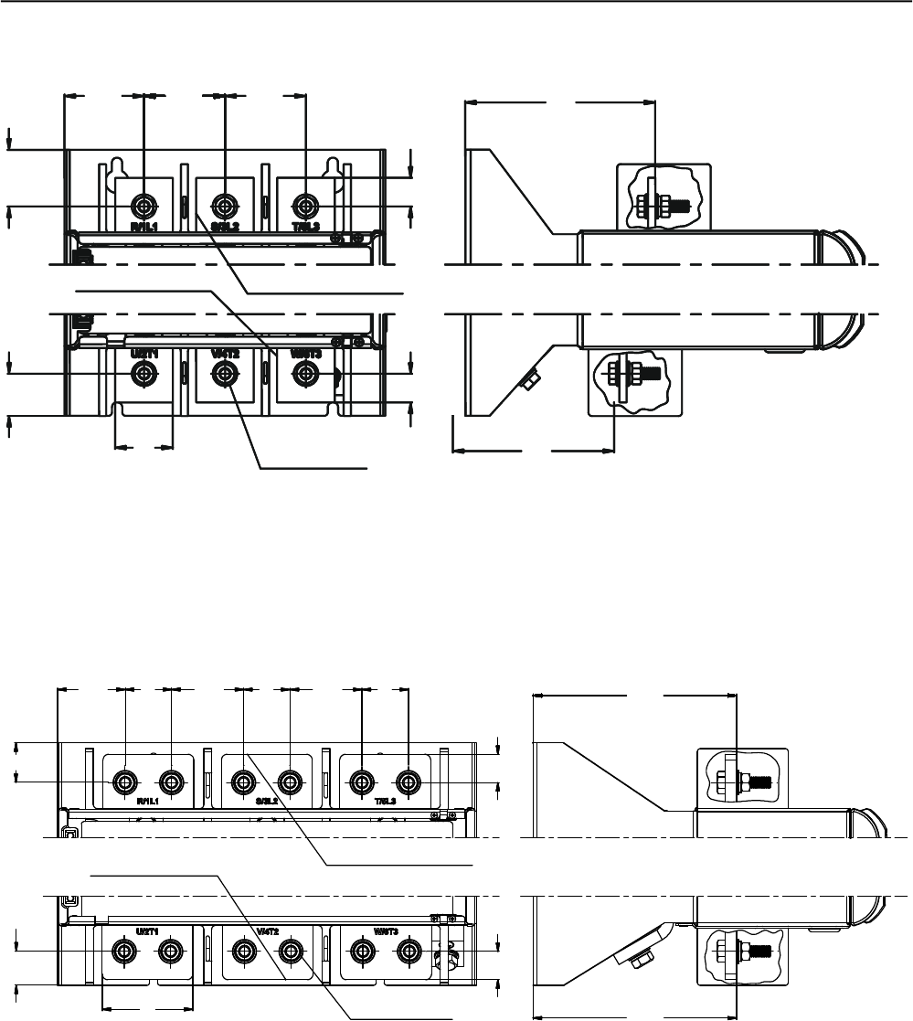
The power connection terminals can be of different sizes and
configurations, depending on the Soft-Starer SSW-06 model as shown
in Figures 3.8 and 3.9.
Terminals:
R / 1L1, S / 3L2 and T / 5L3 : AC supply line
U / 2T1, V / 4T2 and W / 6T3: Motor connection.
3.2.1 Power Terminals
U/2T1 V/4T2 W/6T3 PE
R/1T1 S/3T2 T/5T3
PE
Figure 3.7 - Power/Grounding connections for inside delta motor
connection
R/1L1 S/3L2 T/5L3
Circuit-breaker
Line Fuses
T
S
R
* Dimensions in mm (in)
a) Models: 85A and 130A
Figura 3.8 a) - Maximum tightening torque for power connection
79.5
(3.13)
25
(0.98)
24.5
(0.96)
20
(0.79)
30.6
(1.20)
20
(0.79)
39
(1.54)
39
(1.54)
27
(1.06)
Input Terminal
Power
Stell M6 (6x)
Output Terminal
Power
79.5
(3.13)
CHAPTER 3 - INSTALLATIONAND CONNECTION
33
* Dimensions in mm (in)
b) Models: 170A and 205A
Figura 3.8 b) c) – Power terminals
55.3
(2.18) 56.3
(1.30) 56.3
(1.30)
39.5
(1.56)
Input Terminal
Power
Output Terminal
Power
40
(1.57) Stell M8 (6x)
20
(0.79)
29.4
(1.16)
112
(4.41)
20
(0.79)
132
(5.20)
35
(1.38)
30
(1.18)
80
(3.15)
59.8
(2.35)
41
(1.30)
63.5
(2.50)
41
(1.30)
63.5
(2.50)
41
(1.30)
Input Terminal
Power
Output Terminal
Power
Stell M10 (12x) 179.5
(7.07)
179.5
(7.07)
25
(0.98)
25
(0.98)
* Dimensions in mm (in)
c) Models: 225A, 312A, 365A, 412A, 480A and 604A
CHAPTER 3 - INSTALLATIONAND CONNECTION
34
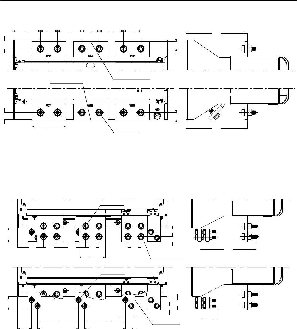
d) Models: 670A and 820A
23.9
(0.94)
120
(4.72)
95
(3.74)
60
(2.36)
85
(3.35)
Input Terminal
Power
Output Terminal
Power
Stell M12 (12x)
214.3
(8.44)
25
(0.98)
25
(0.98)
60
(2.36)
85
(3.35)
60
(2.36)
29.7
(1.17)
214.3
(8.44)
* Dimensions in mm (in)
e) Models: 950A
* Dimensions in mm (in)
22
(0.87)
66.1
(2.60)
51.7
(2.04)
49.5
(1.95)
53.4
(2.10)
156
(6.14) 22
(0.87)
156
22
(0.87)
50
(1.97) Output Bus Bar
Power
22
(0.87)
14
(0.55)
212.2
(8.35)
98.8
(3.89) 49.7
(1.96)
110.3
(4.34)
49.7
(1.96)
100
(3.94)
110.3
(4.34)
49.7
(1.96) Input Bus Bar
Power
40
(1.57)
20
(0.79)
Figura 3.8 d) e) – Power terminals
Stell M12 (12x)
Stell M10 (6x)
CHAPTER 3 - INSTALLATIONAND CONNECTION
35
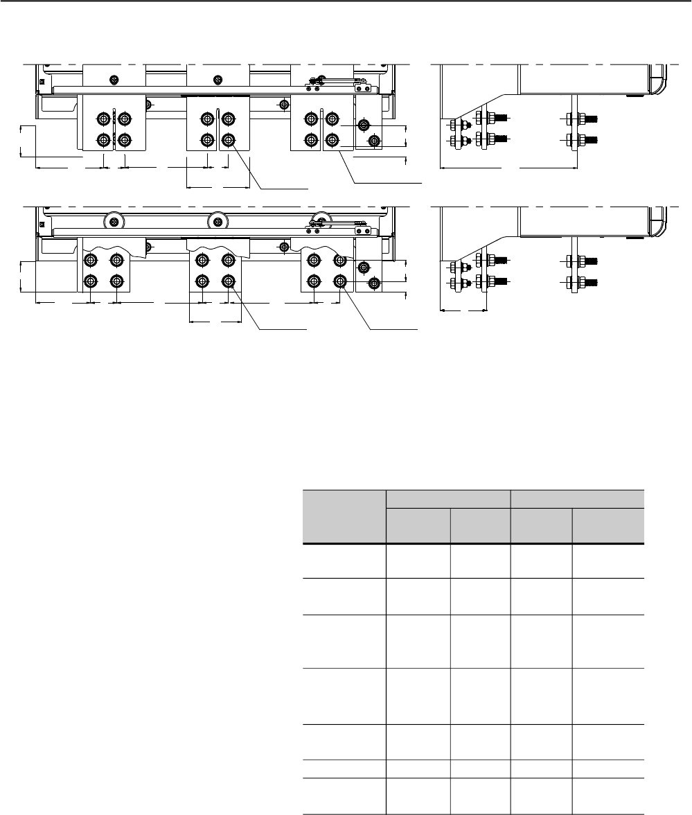
f) Models: 1100A and 1400A
* Dimensions in mm (in)
50
(1.97) 89
(3.50)
60.3
(2.37)
58
(2.28)
104.5
(4.11)
163
(6.42)
100
(3.94)
Output Bus Bar
Power
262
(10.31)
129.4
(5.09) 40
(1.57)
158
(6.22)
40
(1.57)
120
(4.72)
158
(6.22) 40.7
(1.57) Input Bus Bar
Power
40
(1.57)
20
(0.79)
Stell M12 (12x)
50
(1.97)
Stell M12 (12x)
163
(6.42) 50
(1.97)
40
(1.57)
20
(0.79)
Figura 3.8 f) – Power terminals
Table 3.5 - Maximum tightening Torque for power connection
Bolt
M6
(1/4")
M8
(5/16")
M10
(3/8")
M10
M12
M12
M12
SSW-06
SSW-06.0085
SSW-06.0130
SSW-06.0170
SSW-06.0205
SSW-06.0255
SSW-06.0312
SSW-06.0365
SSW-06.0412
SSW-06.0480
SSW-06.0604
SSW-06.0670
SSW-06.0820
SSW-06.0950
SSW-06.1100
SSW-06.1400
Torque
Nm (lb.in)
8.3
(74.38)
19
(166.25)
37
(328.12)
37
61
61
61
Bolt
M6
(1/4")
M6
(1/4")
M10
(3/8")
M10
M10
M10
M10
Torque
Nm (lb.in)
8.3
(74.38)
8.3
(74.38)
37
(328.12)
37
37
37
37
Line / Motor Grounding
CHAPTER 3 - INSTALLATIONAND CONNECTION
36
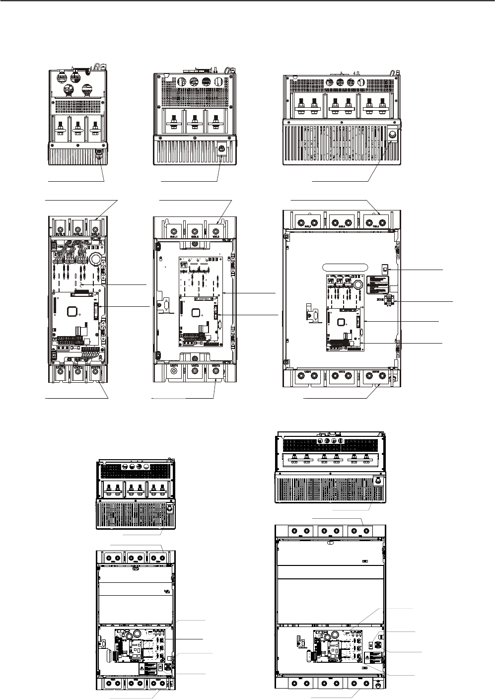
3.2.2 Location of the Power/ Grounding,
Control Connections and Fan Voltage Selection
Figura 3.9 a) to e) - Location of the Power/ Grounding, Control Connections and Fan Voltage Selection
a) Models 85A and 130A b) Models 170A and 205A c) Models 255A ,312A and 365A
d) Models 412A,480A and 640A
e) Models 670A and 820A
Grounding Grounding Grounding
IntputTerminal
Power
IntputTerminal
Power IntputTerminal
Power
Power
Control
Power
Control
FanSupply
Control
Power
Fan
Voltage Selection
110/220V
OutputTerminal
Power
OutputTerminal
Power
OutputTerminal
Power
Control
Power
FanSupply
Fan
Voltage Selection
110/220V
OutputTerminal Power
Intput terminal
Power
Grounding
Control
Power
FanSupply
Fan
Voltage Selection
110/220V
Output Terminal Power
Intput terminal
Power
Grounding
CHAPTER 3 - INSTALLATIONAND CONNECTION
37
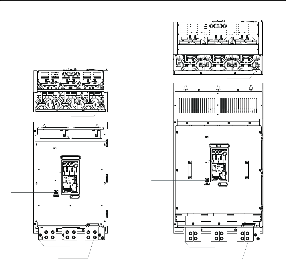
Figure 3.9 f) and g) – Location of the Power, Grounding, Control and Selection Connections
Control
Power
FanSupply
IntputTerminal
Power
OutputTerminal
Power
Control
Power
FanSupply
OutputTerminal
Power
IntputTerminal
Power
f) Model 950A
g) Models 1100A to 1400A
Grounding
Grounding
CHAPTER 3 - INSTALLATIONAND CONNECTION
38
3.2.3 Recommended Power/
Grounding Cables
The described specifications in tables 3,6 and 3,7 are valid only for the
following conditions:
Copper wires with PVC 70°C (158ºF) PVC insulation, for room
temperature of 40°C (104ºF) , installed in perforated and non-
agglomerated conduits
Naked or silver coared copper busbars with round edges and radius
equal to 1 mm with room temperature of 40°C (104ºF) and bus
temperature of 80°C (176ºF).
Obs.: When external By-pass contactors are applied, use the same
cables or busbar applied for the motor connection.
NOTE!
For correct cable dimensioning, consider the installation condition and
the maximum permitted line voltage drop.
Current
100% In
(A)
85
130
170
205
255
312
365
412
480
604
670
820
950
1100
1400
Model
SSW-06.0085
SSW-06.0130
SSW-06.0170
SSW-06.0205
SSW-06.0255
SSW-06.0312
SSW-06.0365
SSW-06.0412
SSW-06.0480
SSW-06.0604
SSW-06.0670
SSW-06.0820
SSW-06.0950
SSW-06.1100
SSW-06.1400
Cables
(mm²)
25
50
70
95
120
185
240
240
300
2 x 150
2 x 185
2 x 240
2 x 300
4 x 150
4 x 185
Bus
(mm x mm)
12 x 2
20 x 3
20 x 3
20 x 3
25 x 5
25 x 5
25 x 5
30x5
40x5
40x5
40x10
40x10
50x10
60x10
80x10
Grounding
Cables
(mm²)
10
25
35
50
70
95
120
120
150
150
185
240
300
2 x 150
2 x 185
Table 3.6 - Minimum specification of cables and busbars for standard
connection
CHAPTER 3 - INSTALLATIONAND CONNECTION
39
Current
100% In
(A)
147
225
294
355
441
540
631
713
831
1046
1160
1420
1645
1905
2424
Model
SSW-06.0085
SSW-06.0130
SSW-06.0170
SSW-06.0205
SSW-06.0255
SSW-06.0312
SSW-06.0365
SSW-06.0412
SSW-06.0480
SSW-06.0604
SSW-06.0670
SSW-06.0820
SSW-06.0950
SSW-06.1100
SSW-06.1400
Line
Cables
(mm²)
70
95
150
185
300
400
500
2 x 185
2 x 240
4 x 120
4 x 150
4 x 185
4 x 240
4 x 300
4 x 500
Line
Bus
(mm x mm)
20 x 3
20 x 3
25 x 5
25 x 5
30 x 5
40 x 5
60 x 5
40x10
40x10
50x10
60x10
80x10
100x10
120x10
160x10
Motor
Cables
(mm²)
25
50
70
95
120
185
240
240
300
2 x 150
2 x 185
2 x 240
2 x 300
4 x 150
4 x 185
Motor
Bus
(mm x mm)
12 x 2
20 x 3
20 x 3
20 x 3
25 x 5
25 x 5
25 x 5
30x5
40x5
40x5
40x10
40x10
50x10
60x10
80x10
Grounding
Cables
(mm²)
10
25
35
50
70
95
120
120
150
150
185
240
300
2 x 150
2 x 185
Table 3.7 - Recommended cables for inside delta motor connection
DANGER!
TheAC input voltage must be compatible with the Soft-Starter SSW-06
rated voltage.
DANGER!
Provide power supplydisconnecting switch. This disconnecting switch
must disconnect the AC input voltage from the Soft-Starter SSW-06,
always when required (for instance during maintenance services).
DANGER!
If a disconnect switch or a contactor is inserted in the motor supply
line, DO NOT operate these devices with running motor or when
Soft-Starter SSW-06 is enabled.
ATTENTION!
Control of overvoltage in the line that supplies the Soft-Starter must be
made using surge protection with a voltage of 680 Vac (phase to phase
connection) and energy absorption capacity of 40 joules (for models
from 85A to 205A) or 80 joules (for models from 255A to 1400A).
NOTE!
Use wire sizing and fuses as recommended in Table 3.6, 3.7 and 3.9.
The connector tightening torque is as indicated in Table 3.5. Use 70ºC
(158ºF) copper wires only.
3.2.4 Connection of the Power
Supply to the Soft-Starter

CHAPTER 3 - INSTALLATIONAND CONNECTION
40
The SSW-06 Soft-Starter is suitable to use in a circuit capable of
supplying at most the current (symmetric Arms) established for each
model, and, respective voltage (V) according to table 3.8. This, when
protected by high speed semiconductor fuses.
3.2.4.1 Power Supply Capacity
Standard
Connection
220-575V (kA)
10
10
10
10
18
18
18
30
30
42
42
85
85
85
85
Model
SSW-06.0085
SSW-06.0130
SSW-06.0170
SSW-06.0205
SSW-06.0255
SSW-06.0312
SSW-06.0365
SSW-06.0412
SSW-06.0480
SSW-06.0604
SSW-06.0670
SSW-06.0820
SSW-06.0950
SSW-06.1100
SSW-06.1400
Inside - Delta
Connection
220-575V (kA)
10
18
18
18
30
30
42
42
42
85
85
85
100
100
125
Table 3.8 - Maximum current capacity of the power supply
The fuses to be used in the input must be high speed semiconductor
fuses with l2t lower of equal to 75% of the SCR value indicated above
(A2s).
These fuses will protect the SRCs in case of a short-circuit. Normal
fuses can also be used, instead of the high speed, which will protect
the installation from short-circuits, but the SCRs will not be protected.
3.2.4.2 Recommended Fuses
Standard
Connection
In (A)
200
250
450
500
500
500
550
700
900
900
900
1400
1600
1600
2000
Model
SSW-06.0085
SSW-06.0130
SSW-06.0170
SSW-06.0205
SSW-06.0255
SSW-06.0312
SSW-06.0365
SSW-06.0412
SSW-06.0480
SSW-06.0604
SSW-06.0670
SSW-06.0820
SSW-06.0950
SSW-06.1100
SSW-06.1400
Delta - Inside
Connection
In (A)
315
350
500
550
700
700
700
1250
1400
1600
1600
2000
2200
2500
3000
I²t of the SCR
(kA²s)
80
84
245
320
238
238
320
1452
4250
4250
4250
4250
14000
14000
15125
Table 3.9 - Recommended Fuses.
CHAPTER 3 - INSTALLATIONAND CONNECTION
41
DANGER!
Power factor correction capacitorsshould never be installed at the output
of the Soft-Starter SSW-06 (U / 2T1, V / 4T2 and W / 6T3).
ATTENTION!
For the protections based on the current reading and indication to work
correctly, in case of overload protection, the rated current of the motor
cannot be lower than 30% of the rated current of the SSW-06
Soft-Starter.
It is not recommended to use motors with the load working duty lower
than 50% of its rated current.
NOTE!
Use wire sizing and fuses as recommended in Table 3.6, 3.7 and 3.9.
The connector tightening torque is as indicated in Table 3.5. Use 70ºC
(158ºF) copper wires only.
NOTE!
Soft-Starter SSW-06 is provided with an electronic protection against
motor overload. This protection must be set according to the specific
motor. When several motors are connected the same Soft-Starter
SSW-06, use individual overload relays for each motor.
The SSW-06 Soft-Starter can be connected to the motor in two
ways, according to 3.2.5.1 and 3.2.5.2.
3.2.5 Connection of the
SSW-06 Soft-Starter
to the motor
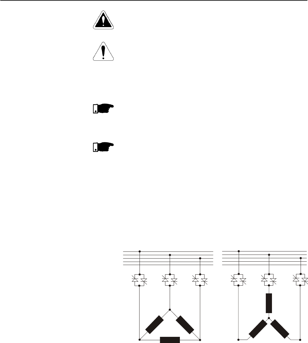
3.2.5.1 Standard Three-Wire
Connection
(P150=0=Inactive)
The standard 3 wires connection allows the SSW-06 Soft-Starter line
current to be equal to the motor current.
Figure 3.10 - Soft-Starter SSW-06 with standard connection
1/U1
4/U2 2/V1
5/V2
6/W2
3/W1
2/V1
5/V2
1/U1
4/U2 6/W2
3/W1
R
S
T
N
P E
R
S
T
N
P E
R
U
S
VW
TR
U
S
V
T
W
CHAPTER 3 - INSTALLATIONAND CONNECTION
42
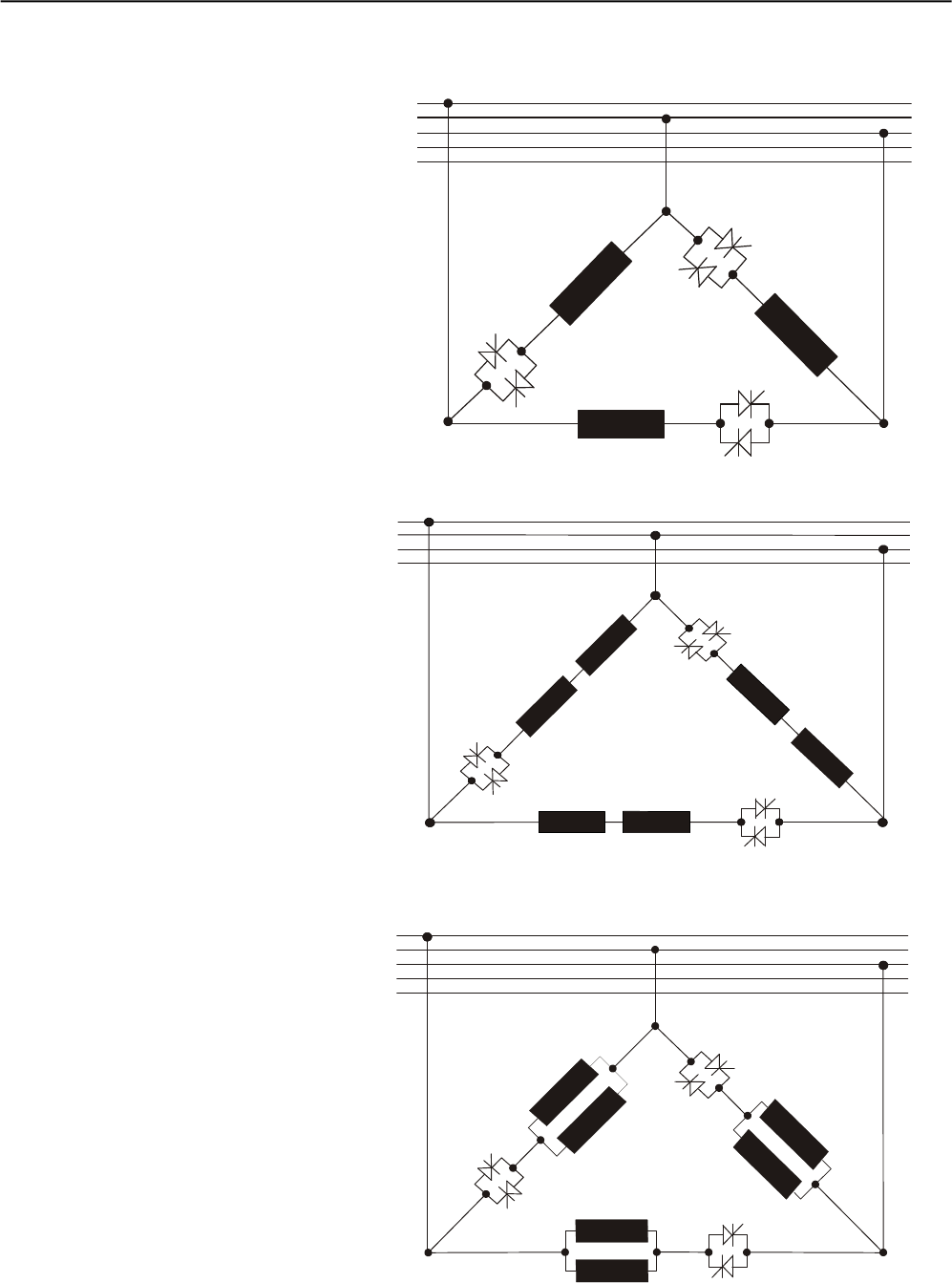
3.2.5.2 Inside Delta
Motor Connection
(P150=1=Active)
In this kind of connection, the SSW-06 Soft-Starter line current is equal
to approximately 58% of the rated current of the motor.
Figure 3.11 - Soft-Starter SSW-06 Inside Delta Motor Connection
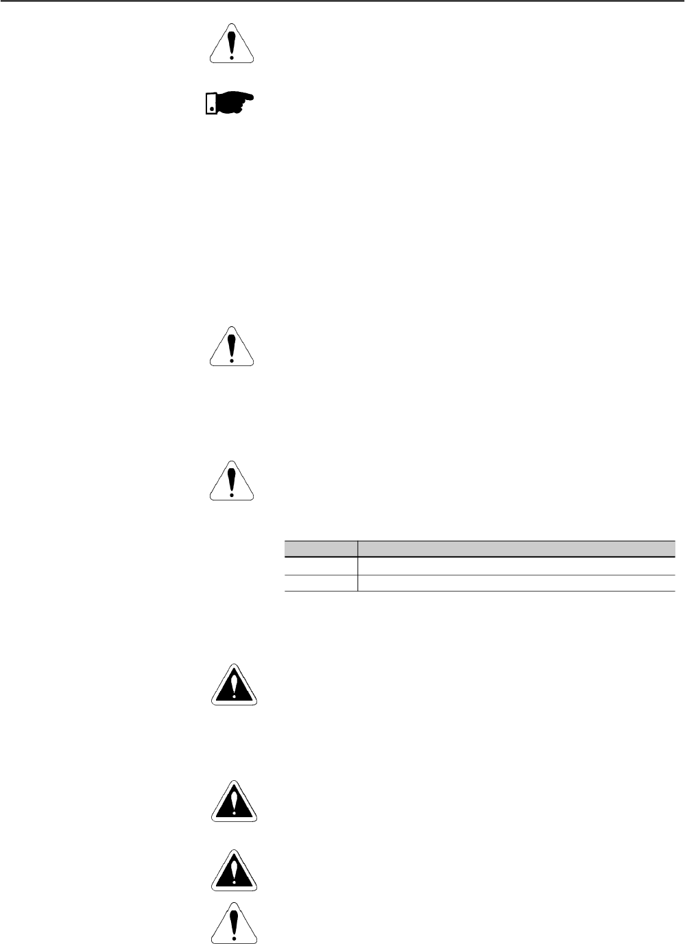
Figure 3.12 - Soft-Starter SSW-06 Inside Delta Motor Connection - motor
with double delta series connected.
S
S
V
W
R
R
T
T
U
R
S
T
N
PE
2/V1
5/V2
6/W2
3/W1
8/V3
11/V4
7/U3
10/U4
12/W4
9/W3
1/U1
4/U2
Figure 3.13 - Soft-Starter SSW-06 Inside Delta Motor Connection - motor
with double delta parallel connected.
1/U1
4/U2
2/V1
5/V2
6/W2
3/W1
R
S
T
N
PE
S
S
V
W
RRT
T
U
2/V1
5/V2
6/W2 3/W1
8/V3
11/V4
12/W4 9/W3
7/U3
10/U4
1/U1
4/U2
R
S
T
N
PE
R
S
W
T
S
R
T
V
U
CHAPTER 3 - INSTALLATIONAND CONNECTION
43
ATTENTION!
For the connection inside the delta of the motor, the motor must have a
delta connection in the desired voltage.
NOTES!
1) In the motor inside delta connection, the SSW-06 Soft-Starter
connection cables to the power supply, fuses and/or the main
contactor must support the rated current of the motor. The motor
connection cables to the Soft-Starter and/or the external By-pass
contactor connection must support 58% of the rated current of the
motor.
2) Due to the presence of high currents and large cable sizes
requirements, we also recommend the use of copper busbars for
connecting the Soft-Starter SSW-06 to the power supply.
3) During the start of the motor current in relation to the Soft-Starter is
1.50. However in full voltage condition (after the start time of the
motor) the current relation is 1.73.
ATTENTION!
Pay attention to the connection of the motor to the SSW-06 Soft-Starter,
respect the connection diagrams shown in the figures above according
to the type of motor windings. If it is necessary to change the motor
speed direction, only invert the SSW-06 Soft-Starter connections to the
power supply.
Maintain the electronics turned off during the connection changes.
ATTENTION!
Ensure correct setting of Parameter P150 before the motor is switched
ON. Soft-Starter SSW-06 maybedamaged, when this parameter setting
is not correct
P150 Action
0 (Inactive) Soft-Starter SSW-06 with standard connection to motor
1 (Active) Soft-Starter SSW-06 inside of the delta motor connection
DANGER!
The Soft-Starter SSW-06 must be grounded for safetypurposes (PE).
The earth or ground connection must complywith the local regulations.
For grounding, use cables with cross section as indicated in Table 3.6.
Make the ground connection to a grounding bar or to the general
grounding point (resistance 10 ohms).
DANGER!
The AC input for the Soft-Starter SSW-06 must be grounded.
DANGER!
Do not use the neutral conductor for grounding purpose. Use a specific
ground conductor.
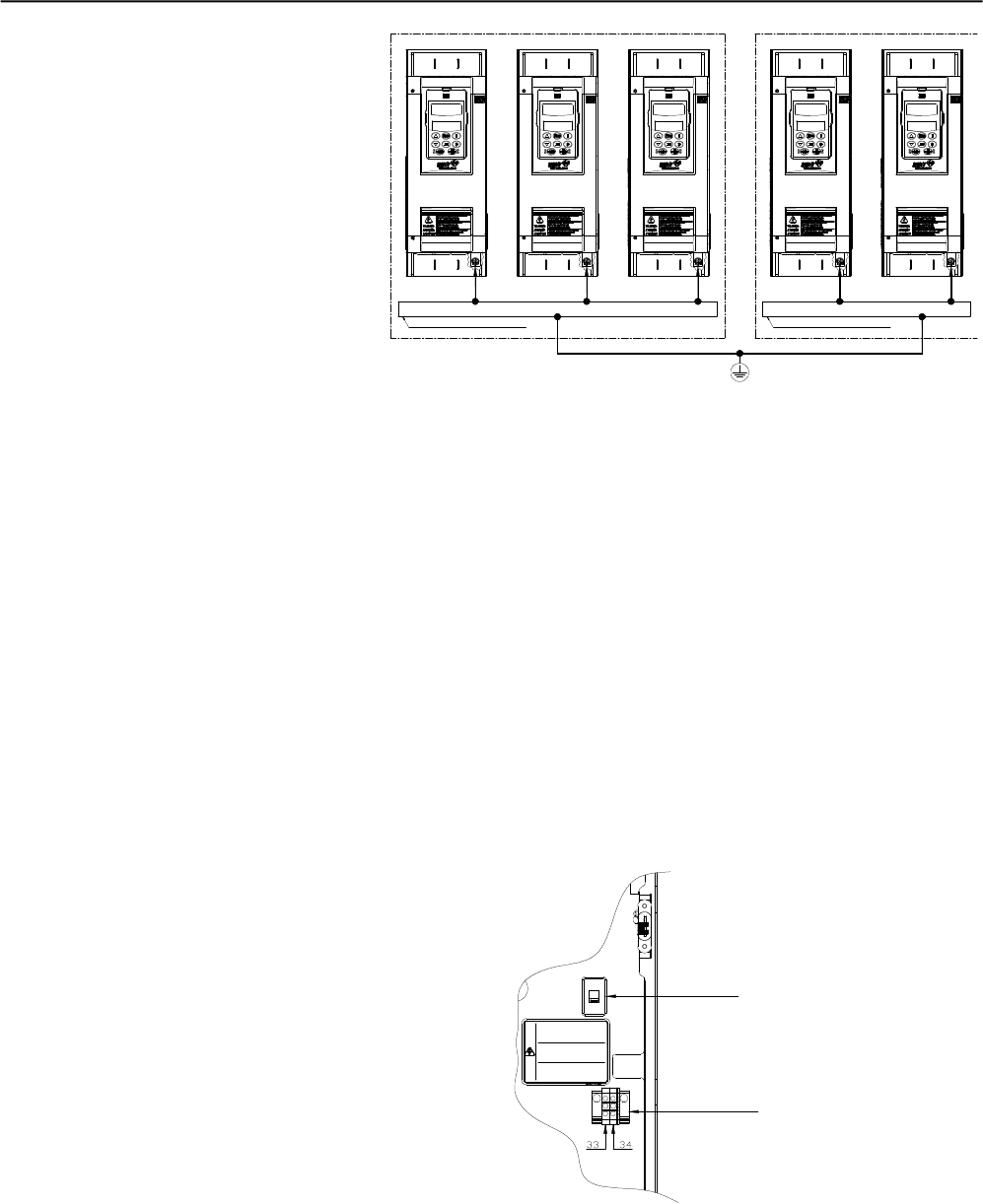
ATTENTION!
Do not share the ground wiring with other equipment that operate with
high currents (for instance, high voltage motors, welding machines, etc).
When more than one self-starter SSW-06 used, see 3.14 figure.
3.2.6 Grounding Connections
Table 3.10 - Connection of the Soft-Starter to the motor
CHAPTER 3 - INSTALLATIONAND CONNECTION
44
EMI – Electromagnetic interference:
The Soft-Starter SSW-06 is developed to be used in industrial systems
(ClassA) as per Norm EN60947-4-2.
It’s necessary to have a distance of 0,25m (10in) between the Soft-
Starter SSW-06 and the cables between the Soft-Starter SSW-07 and
the motor. Example:PLC wiring, temperature controllers, thermocouple
cables, etc.
Grounding the motor frame:
Always ground the motor frame. Ground the motor in the panel where
the Soft-Starter SSW-06 is installed. The Soft-Starter SSW-06 output
wiring to the motor must be laid separately from the input wiring, as
well as from the control and signal cables.
Figure 3.14 - Grounding connections for more than one
Soft-Starter SSW-06
Grounding bar
Internal to the Panel Grounding bar
Internal to the Panel
3.2.7 Fan Connections Available in models 255A to 820A. The rated voltage of the fans can
also be selected.
Figura 3.15 – Selection of the Fan Voltage
X1E
ALIMENTAÇÃO
VENTILADOR
SELEÇÃO
DE TENSÃO
110/220V
ATEN ÇÃO!
SELEC IONE A TENS ÃO DOS VENTI LADORES
DE ACOR DO COM A TENSÃ O APLICADA AOS
BORN ES X1:33 E X 1:34
ATTE NTION!
SELEC T THE FAN V OLTAGE IN ACCO RDANCE
WITH THE V OLTAGE AP PLIED TO THE
TERM INALS X1: 33 AND X1 :34
ATENC ION!
SELEC CIONAR LA TE NSION DE LOS VE NTILADORE S
DE A CUERDO CON LA TE NSION A PLICADA A LOS
BORN ES X1:3 3 Y X1:34
!
Voltage Selection
110/220V
Fan
Fan Power Supply
Connector X1E pins 33 and 34. More details see figure 3.16.
CHAPTER 3 - INSTALLATIONAND CONNECTION
45
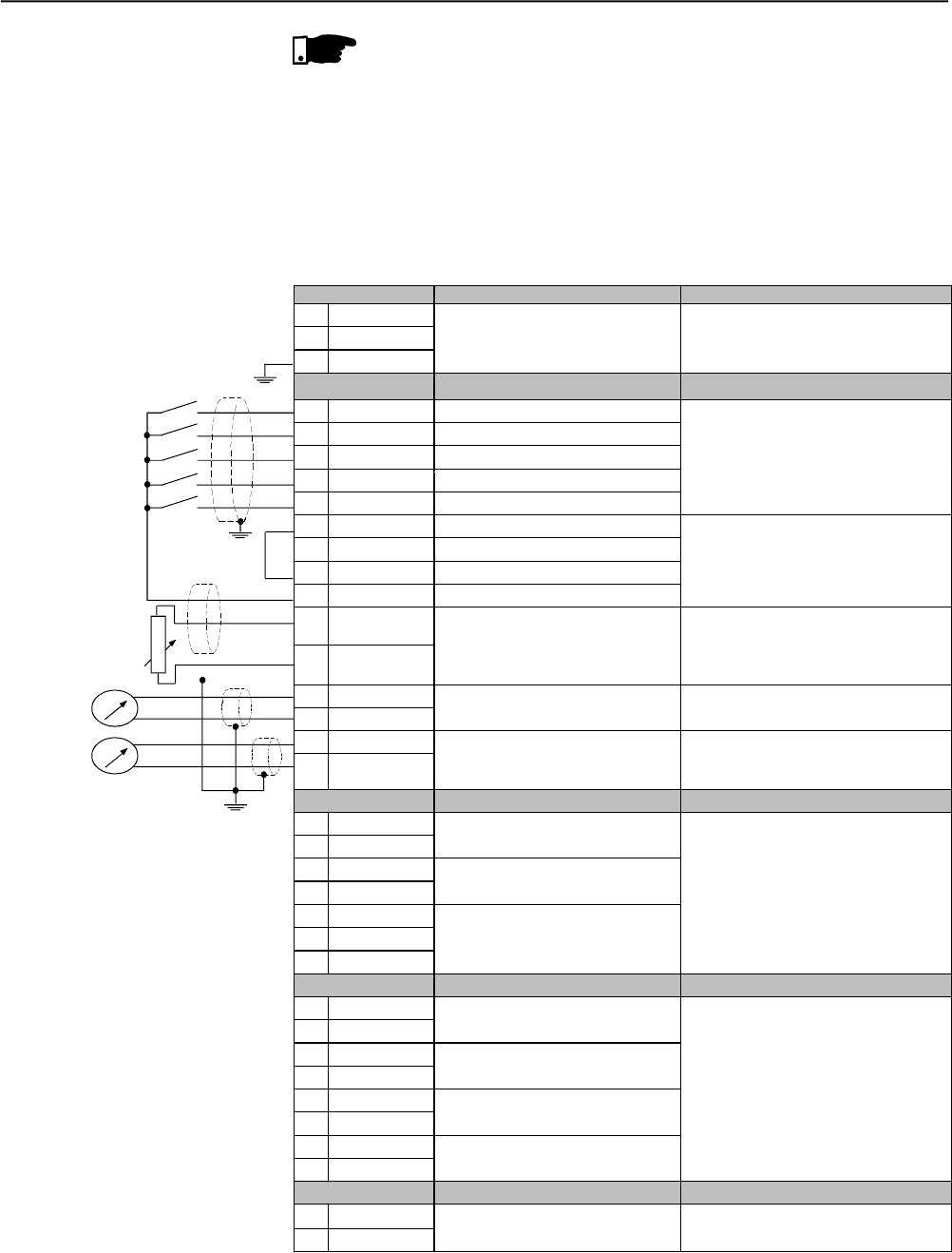
3.2.8 Signal and Control
Connections The signal connections (analog outputs) and control (relay inputs and
outputs) are made on the electronic card connectors.
Conectors:
CCS6 and CPS63 to the models 85A to 365A and 950A to 1400A.
CCS6 and CPS64 to the models 412A to 820A.
NOTE!
The fans are switched on if the heatsink temperature is above 70ºC
(158ºF). Do not forget to connect the fan power supply and select the
fan supply voltage for the models higher than 255A.
Conector X1A Description Specifications
1 Phase
2 Neutral
PE Ground
Eletronic Supply (110 to 230)Vac (-15% to +10%) or
(94 to 253)Vac
Operation Current: 280nA Max.
Connector X1B Factory Standard Function Specifications
3 DI1 Motor Enable/Disable
4 DI2 Error Reset
5 DI3 Not Used
6 DI4 Not Used
7 DI5 Not Used
5 isolated digital inputs
Minimum high level: 18Vdc
Maximum low level: 3Vdc
Maximum voltage: 30Vdc
Input current: 11mA@24Vdc
8 COM Common point of the Digital Inputs
9 COM Common point of the Digital Inputs
10 DGND 0V reference of the 24Vdc source
11 24Vcc Digital Input Supply
Only use for Digital Inputs
12 PTCB
13 PTCA DI6 - Not Used
Operation: 3k9Release: 1k6
Minimum resistance: 110
PTCB referenced to DGND
Through 249resistor
14 AGND
15 AO1 Input for motor Thermistor (0 to 10)V, RL 10k (maximum load)
Resolution: 11 bits
16 AGND
17 AO2 Analog Output 1 - Not used (0 to 20)mA or (4 to 20)mA
RL=500/1%@10V
Resolution: 11 bits
Conector X1C Factory Standard Function Specifications
18 RL1 NA
19 RL1 NA Relay Output - Run
20 RL2 NA
21 RL2 NA Relay Output - Full Voltage
22 RL3 NA
23 RL3 C
24 RL3 NF
Relay Output – No Error
Contactor capacity:
1A
24Vac
Conector X1D Description Specifications
25 TERM.
26 TERM. Over-temperature thermostat
27 TC 1/R VER
28 TC 1/R PRET Current transformer phase R
29 TC 2/S VER
30 TC 2/S PRET Current transformer phase S
31 TC 3/T VER
32 TC 3/T PRET Current transformer phase T
Internal connection of the Soft-Starter
Connector X1E Descrição Specifications
33 Phase
34 Neutral Fan Supply (from model 255A) (101 to 127)Vac or (207 to 253)Vac
Operation current: see table 3.4
PTC
Nota: NC = Normally Closed Contact
NO = Normally Open Contact
C = Common
Figure 3.16 - Control Terminal Description
CHAPTER 3 - INSTALLATIONAND CONNECTION
46
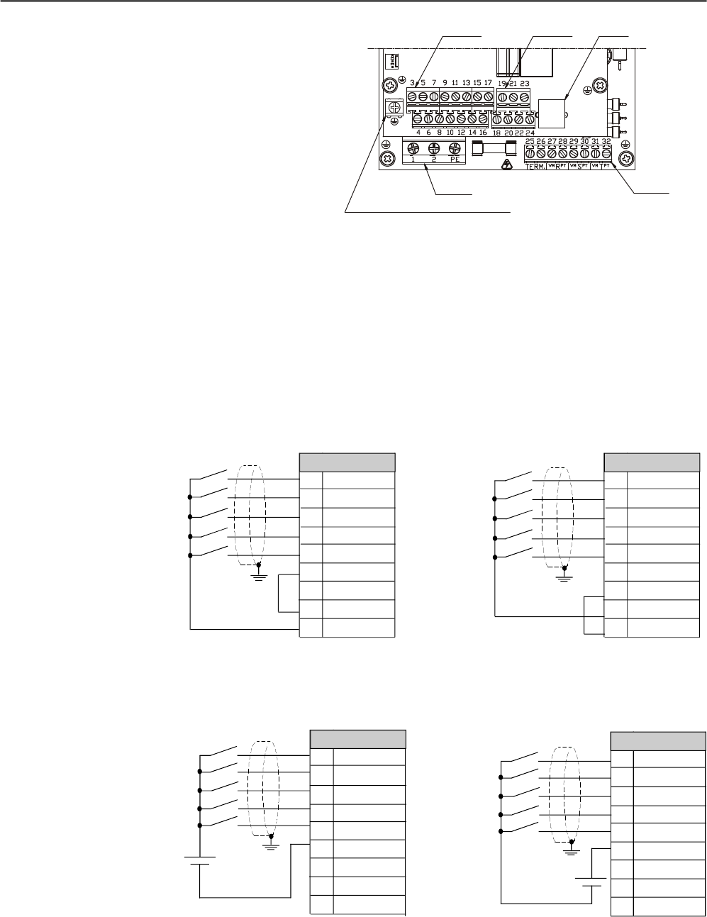
Figure 3.17 - Control connector disposition
Figure 3.18 - Connection diagram of the digital inputs using an the auxiliary internal source
Figure 3.19 - Connection diagram of the digital inputs using an external source
For signal and control wire installation, adopt the following
procedures:
1) The connections of the SSW-06 digital inputs can be carried out in
several ways. Theycan be supplied by auxiliaryinternal +24Vdc source
byusing the 0V as a common point or bythe +24Vdc source. Depending
on the application requirements,they can also be supplied by external
+24Vdc source , connected to PLCs, by using the 0V as common
point or by the +24Vdc source.:
Connector X1B
3 DI1
4 DI2
5 DI3
6 DI4
7 DI5
8 COM
9 COM
10 DGND
11 24Vdc
Connector X1B
3 DI1
4 DI2
5 DI3
6 DI4
7 DI5
8 COM
9 COM
10 DGND
11 24Vdc
Connector X1B
3 DI1
4 DI2
5 DI3
6 DI4
7 DI5
8 COM
9 COM
10 DGND
11 24Vdc
Connector X1B
3 DI1
4 DI2
5 DI3
6 DI4
7 DI5
8 COM
9 COM
10 DGND
11 24Vdc
To be used for grounding of shield of
the signal an control cables
XO
X1A
X1B X1C X2
X1D
24Vdc
+
24Vdc
+
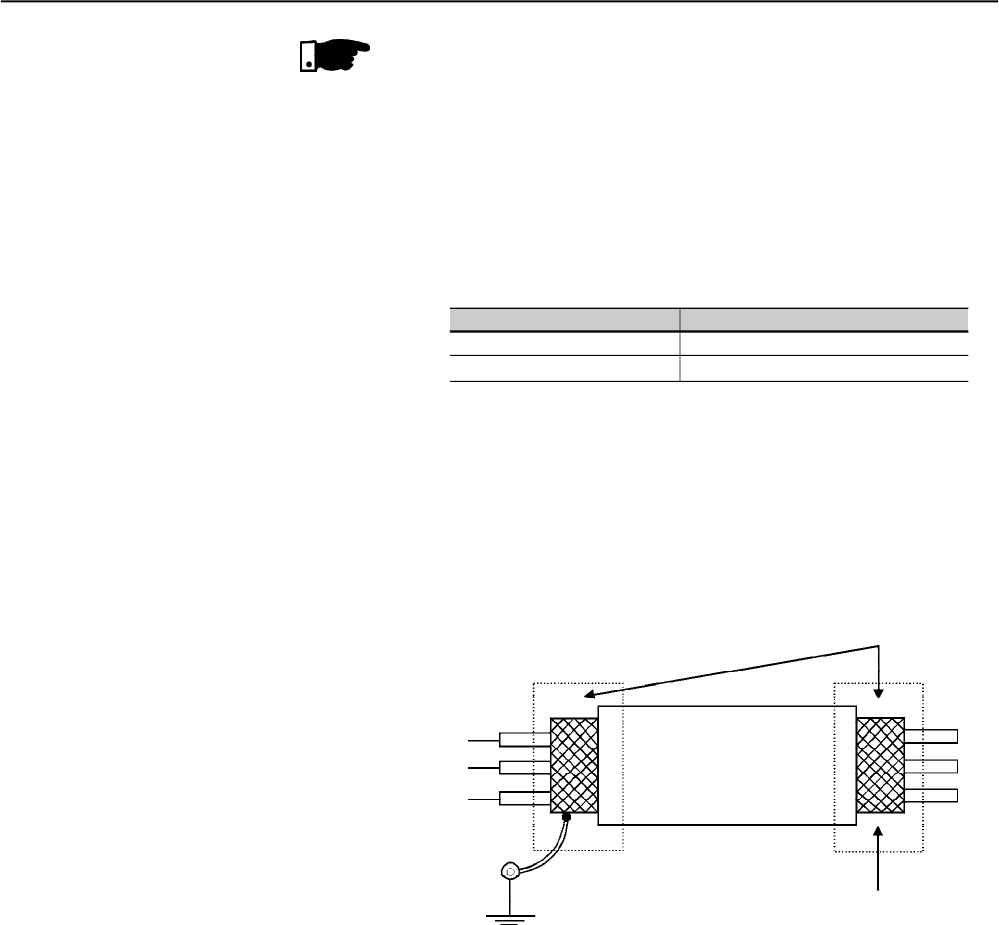
CHAPTER 3 - INSTALLATIONAND CONNECTION
47
Table 3.11 - Wiring separation distances
If the crossing of these cables is unavoidable, install them perpendicu-
lar, maintaining a minimum separation distance of 5cm (2 in) at the
crossing point.
Connect the shield as shown below:
6) For wiring distances longer than 50m (150ft), it is necessary to use
galvanic isolators for the X1B:3...17signals.
7) Relays, contactors, solenoids or electromagnetic braking coils
installed near Soft-Starters can generate interference in the control
circuit. In order to eliminate this interference, connectRC suppressors
in parallel with the coils of AC relays. Connect a free - wheeling diode
in case of DC relays/coils.
8) When an external keypad (HMI) is used (Refer to Chapter 8),
separate the cable that connects the keypad to the Soft-Starter
SSW-06 from other cables, maintaining a minimum distance of 4 in
(10 cm) between them.
Wiring Length Min. separation distance
30 m (98.4 ft) 10 cm (3.94 in)
> 30 m (98.4 ft) 25 cm (9.84 in)
Insulate with tape
Do not ground
Soft-Starter side
Connect to ground
Screw located on the CCS6 board
Figure 3.20 - Shield connection
NOTE!
1) The auxiliary electronic power supply of the SSW-06 Soft-Starter of
+24Vdc shall only be used for the supply of the digital inputs.
2) The SSW-06 Soft-Starter factory default is with the pins 8 and 10 of
the X1B connector switched on (wire bridge).
3) Cable cross section (0,5 to 1,5) mm2;
4) Maximum torque: 0.50 N.m (4.50 ibf.in).
5) X1B wiring must be connected with shielded cables and installed
separately from other wiring (power, control at 110V/220V, etc.),
according to Table 3.11.
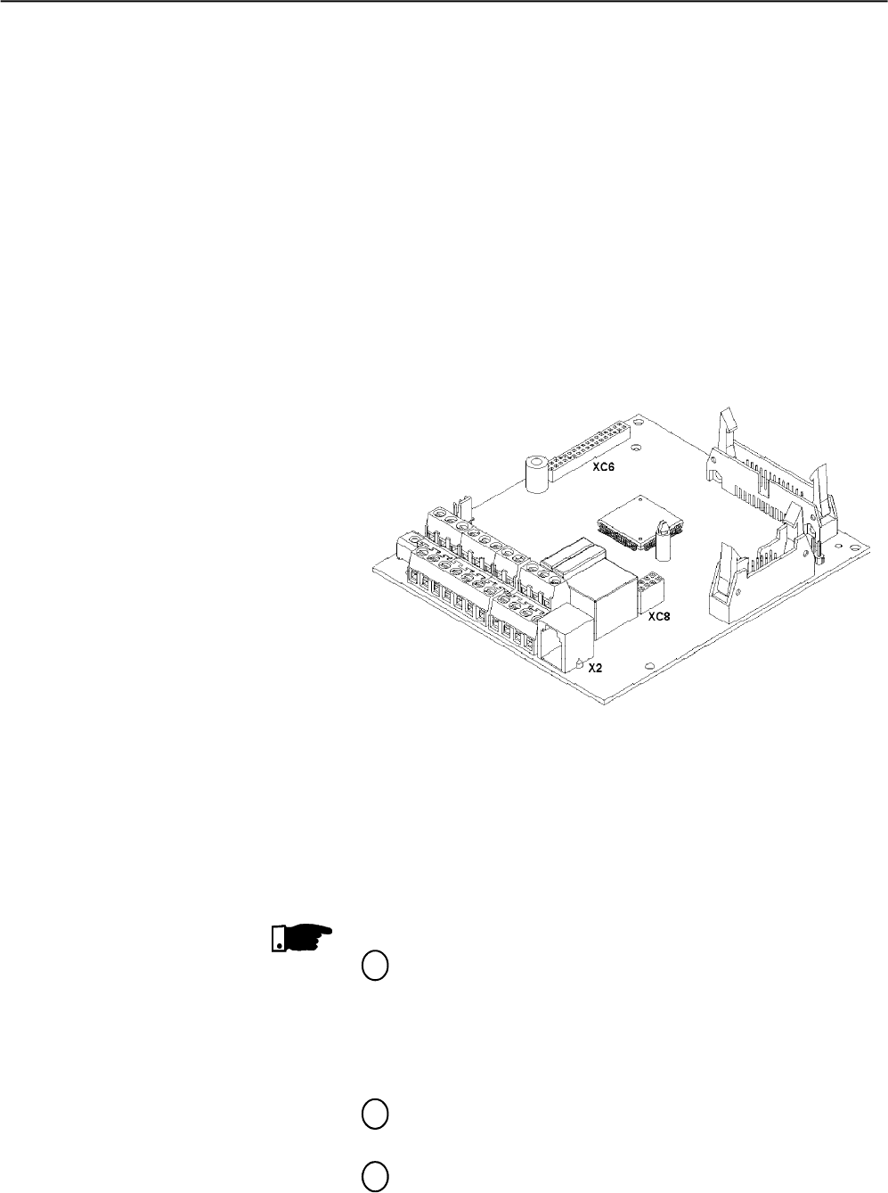
CHAPTER 3 - INSTALLATIONAND CONNECTION
48
An optional Profibus DP or DeviceNet Communication board can be
attached to this connector.
For more details see the Profibus DP or DeviceNet Communication
Manual of the Soft-Starter SSW-06 and chapter 9.
3.2.11 XC6 Fieldbus
Communication Board
Connection
Figure 3.21 – X2, XC6 and XC8 Connector
3.3 RECOMMENDED
SET-UPS
In this item some suggestive starters are presented, which can be
used completely or in part to elaborate the desired control.
The main warnings, for all the suggestive starters, listed below, are
related in the diagrams through their respective numbers.
NOTES!
For the protection of all of the electrical installation, the use of
fuses or circuit breakers in the main power supply circuit is
necessary.
The use of high speed semiconductor fuses are not necessary
for the functioning of the SSW-06 Soft-Starter, but its use is
recommended for the complete protection of the thyristors.
The transformer “T1” is optional and should be used when the
line voltage is different from the electronics and fan voltage;
To protect the motor against destruction by possible short-
circuits in the power circuit of the Soft-Starter SSW-06 use an
isolating contactor (K1) or circuit-breaker (Q1);
3.2.9 RS-232, X2 Serial
Communication Connection
3.2.10 RS-485, XC8 Isolated Serial
Communication Board
Connection
This connector is used to make a standard RS232 communication line
between the Soft-Starter SSW-06 and a PC and/or PLC.
For more details see the Serial Communication Manual of the
Soft-Starter SSW-06.
An optional board of serial communication, standard RS-485 with
galvanic insulation, can be attached to this connector.
For more details see the Serial Communication Manual of the
Soft-Starter SSW-06.
1
2
3

CHAPTER 3 - INSTALLATIONAND CONNECTION
49
ATTENTION!
In the first power-up, in the models of 85A to 365A, if a contactor or a
circuit-breaker of insulation of the power supply with under voltage
release will not be used, to connecting the control power supply first,
program the minimum necessaryparameters and onlyafter connecting
the power supply.
X1E (33 and 34) is only available in the models fitted with cooling
fans;
For integral motor protection the installation of one or more PTC
thermistors (PTC at the DI6) or thermostats (external fault at
the DI4 to DI6) is recommended;
Remember that when a command via two-wire digital input is
used (the switch is normally open with retention), every time the
power supplyreturns, after any fault, the motor starts immediately
if the switch remains closed;
In case of maintenance services, remove the power supply fuses
or disconnect the power supply, thus ensuring complete
equipment disconnection from the power supply;
The emergency stop can be obtained by disconnecting the
electronics power supply.
The contactors must be of the same model and must support
the motor starting current. For safety reasons, auxiliary contacts
must be used to keep both contactors from closing at the same
time.
Use a digital input set to “General Enable” to dissable the motor
without braking. Use a digital input set to “No Braking”, for safety
reasons, with the possibility of putting a motor stop sensor to
disable the braking.
The use of an external By-pass contactor is optional for models
950A to 1400A that do not have an internal By-pass contactor.
This contactor is also recommended, in models with an internal
by-passs, for use in applications where the motor can frequently
present a blocked rotor during the full operation cycle.
To maintain the current indications and protections, when using
the external By-pass contactor, it is necessary to place the
current transformers in the soft starter output. The current
transformers must be placed in the correct positions and
directions as indicated.
5
6
4
7
8
9
10
11
12
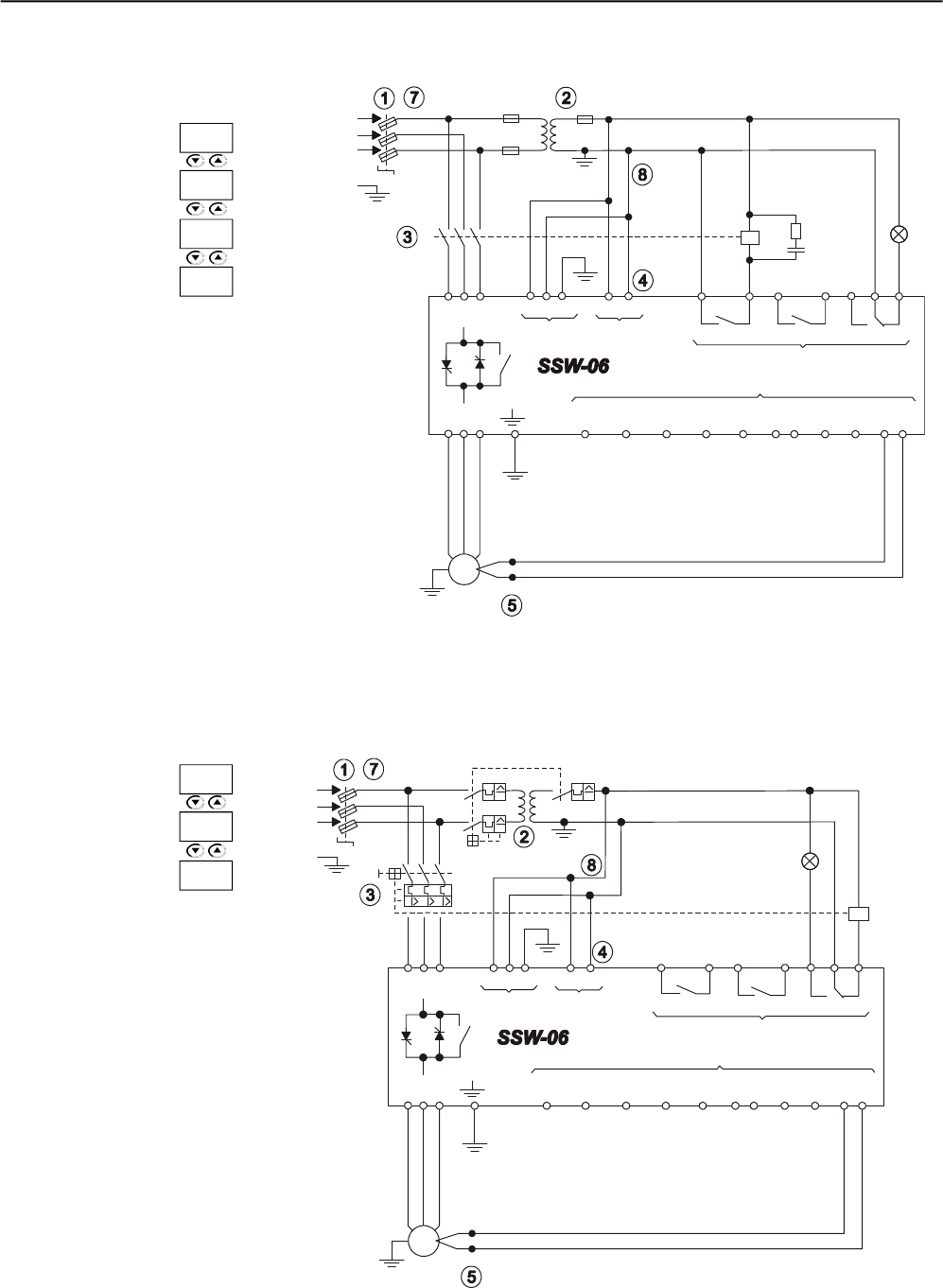
CHAPTER 3 - INSTALLATIONAND CONNECTION
50
3.3.1 Recommended Set-ups by Keypad (HMI) Command With Isolating Contactor.
Figure 3.22 - Recommended Set-ups by Keypad (HMI) command with isolating contactor
See note in 3.3
+ to
M
3~ PTC
R
S
T
PE
K1
R S T 1 2 PE 33 34
X1EX1A
18 19
RL1 RL2
20 21 22 23 24
RL3
X1C
X1B
Dl1
3
Dl2
4
Dl3
5
Dl4
6
Dl5
7
COM
8 9
0V
10
24V
11
PTC
B A
12 13
U V W
Fault
T1
K1
P279 =6
P277 =1
P229 =0
P220 =0
3.3.2 Recommended Set-ups by Keypad (HMI) Command with Circuit-breaker.
Figure 3.23 - Recommended Set-ups by Keypad (HMI) command with circuit-breaker
See note in 3.3
R
S
T
PE
Q1
R S T 1 2 PE 33 34
X1E
X1A
18 19
RL1 RL2
20 21 22 23 24
RL3
X1C
X1B
Dl1
3
Dl2
4
Dl3
5
Dl4
6
Dl5
7
COM
8 9
0V
10
24V
11
PTC
B A
12 13
U V W
Fault
T1
Q1
Circuit-
breaker with
under voltage
release
Q2
+ to
M
3~
PTC
P279 =7
P229 =0
P220 =0
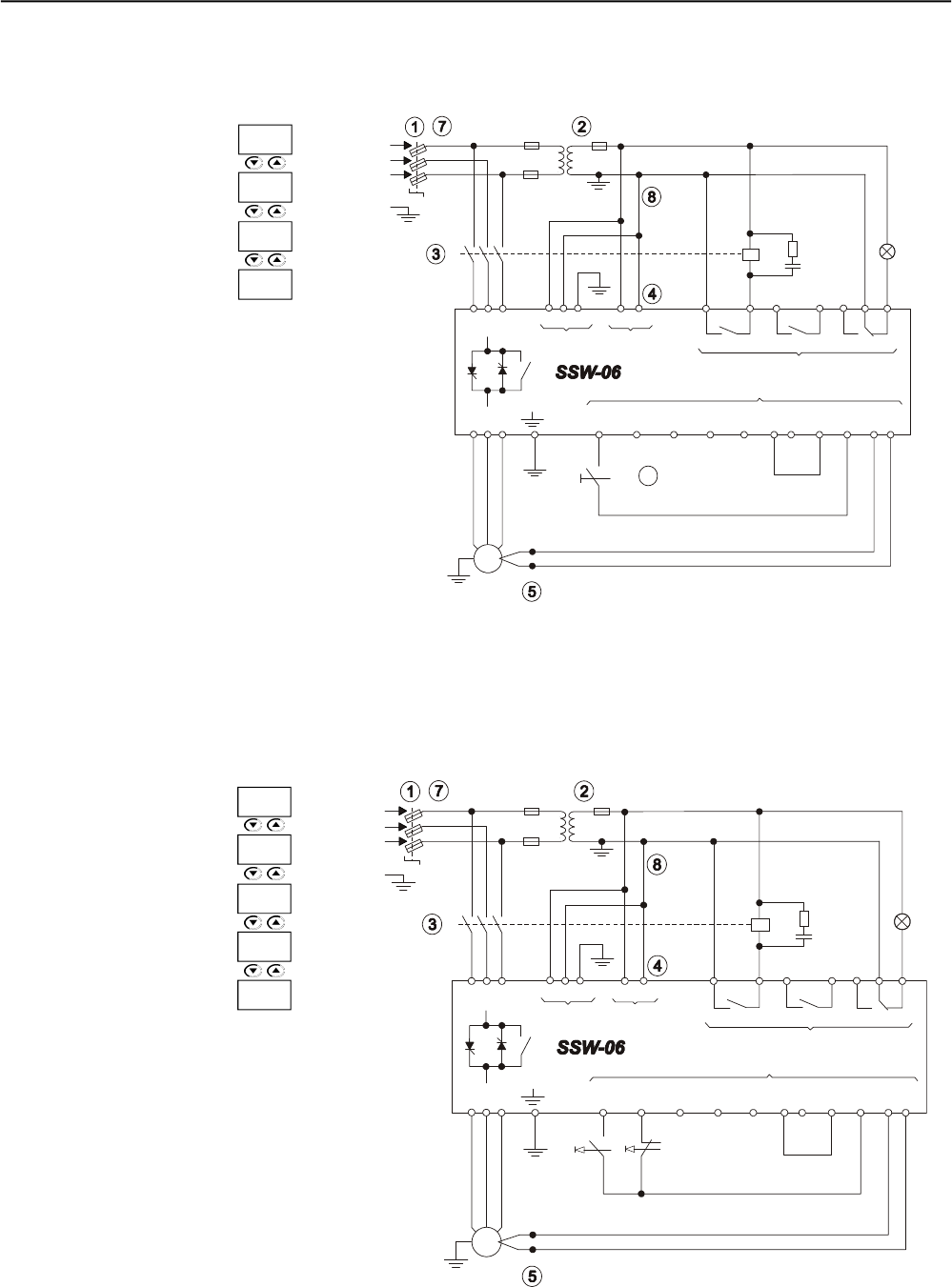
CHAPTER 3 - INSTALLATIONAND CONNECTION
51
3.3.3 Recommended Set-ups with Command via Two-wire Digital Inputs.
Figure 3.24 - Recommended set-ups with command via two-wire digital inputs
See note in 3.3
+ to
M
3~ PTC
R
S
T
PE
K1
R S T 1 2 PE 33 34
X1EX1A
18 19
RL1 RL2
20 21 22 23 24
RL3
X1C
X1B
Dl1
3
Dl2
4
Dl3
5
Dl4
6
Dl5
7
COM
8 9
0V
10
24V
11
PTC
B A
12 13
U V W
Fault
T1
K1
Enable
Disabela
P279 =6
P277 =1
P230 =1
P220 =1
6
3.3.4 Recommended Set-ups with Command via Three-wire Digital Inputs.
Figure 3.25 – Recommended set-ups with command via three-wire digital inputs
See note 3.3.
+ to
M
3~ PTC
R
S
T
PE
K1
R S T 1 2 PE 33 34
X1E
X1A
18 19
RL1 RL2
20 21 22 23 24
RL3
X1C
X1B
Dl1
3
Dl2
4
Dl3
5
Dl4
6
Dl5
7
COM
8 9
0V
10
24V
11
PTC
B A
12 13
U V W
Fault
T1
K1
Enable
Disable
P277 =1
P264 =1
P230 =1
P220 =1
P279 =6
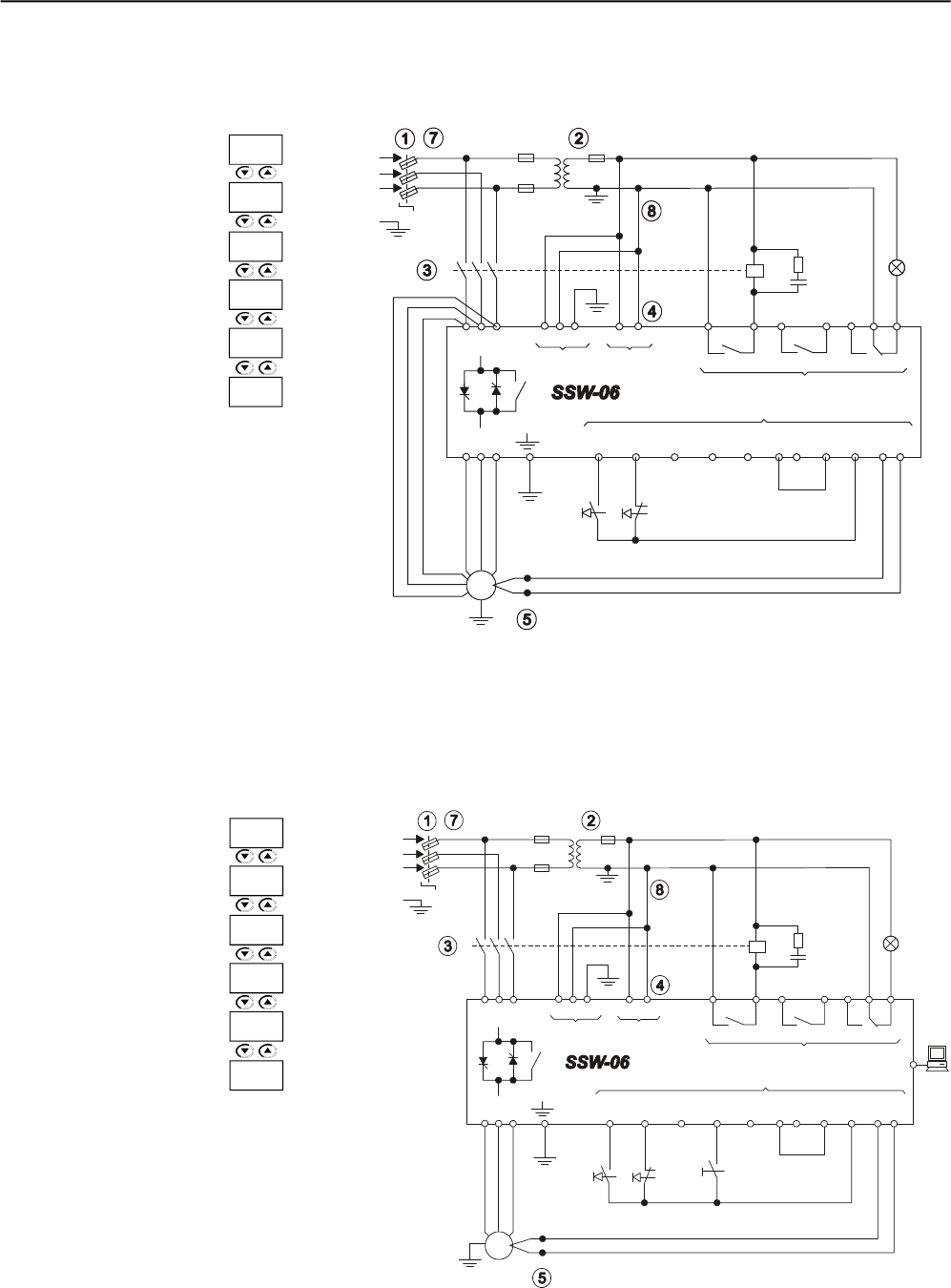
CHAPTER 3 - INSTALLATIONAND CONNECTION
52
3.3.6 Recommended Set-ups with Command via Three-wire Digital Input or Serial
Communication.
Figure 3.27 - Recommended set-ups with command via three-wire digital input or serial
communication
See note 3.3
+ to
M
3~
R
S
T
PE
K1
R S T 1 2 PE 33 34
X1E
X1A
18 19
RL1 RL2
20 21 22 23 24
RL3
X1C
X1B
Dl1
3
Dl2
4
Dl3
5
Dl4
6
Dl5
7
COM
8 9
0V
10
24V
11
PTC
B A
12 13
U V W
Fault
T1
K1
Enable
Disable
PTC
X2 PC
Local
Remote
3.3.5 Recommended Set-ups with Command via Three-wire Digital Input and Inside Delta
Motor Connection.
Figure 3.26 – Recommended set-ups with command via three-wire digital input and inside
delta motor connection.
See notes 3.3
and 3.2.5.2.
+ to
M
3~
R
S
T
PE
K1
R S T 1 2 PE 33 34
X1E
X1A
18 19
RL1 RL2
20 21 22 23 24
RL3
X1C
X1B
Dl1
3
Dl2
4
Dl3
5
Dl4
6
Dl5
7
COM
8 9
0V
10
24V
11
PTC
B A
12 13
U V W
Fault
T1
K1
Disable
Enable
PTC
P264 =1
P230 =1
P220 =1
P150 =1
P277 =1
P279 =6
P264 =1
P230 =2
P229 =1
P220 =4
P277 =1
P279 =6
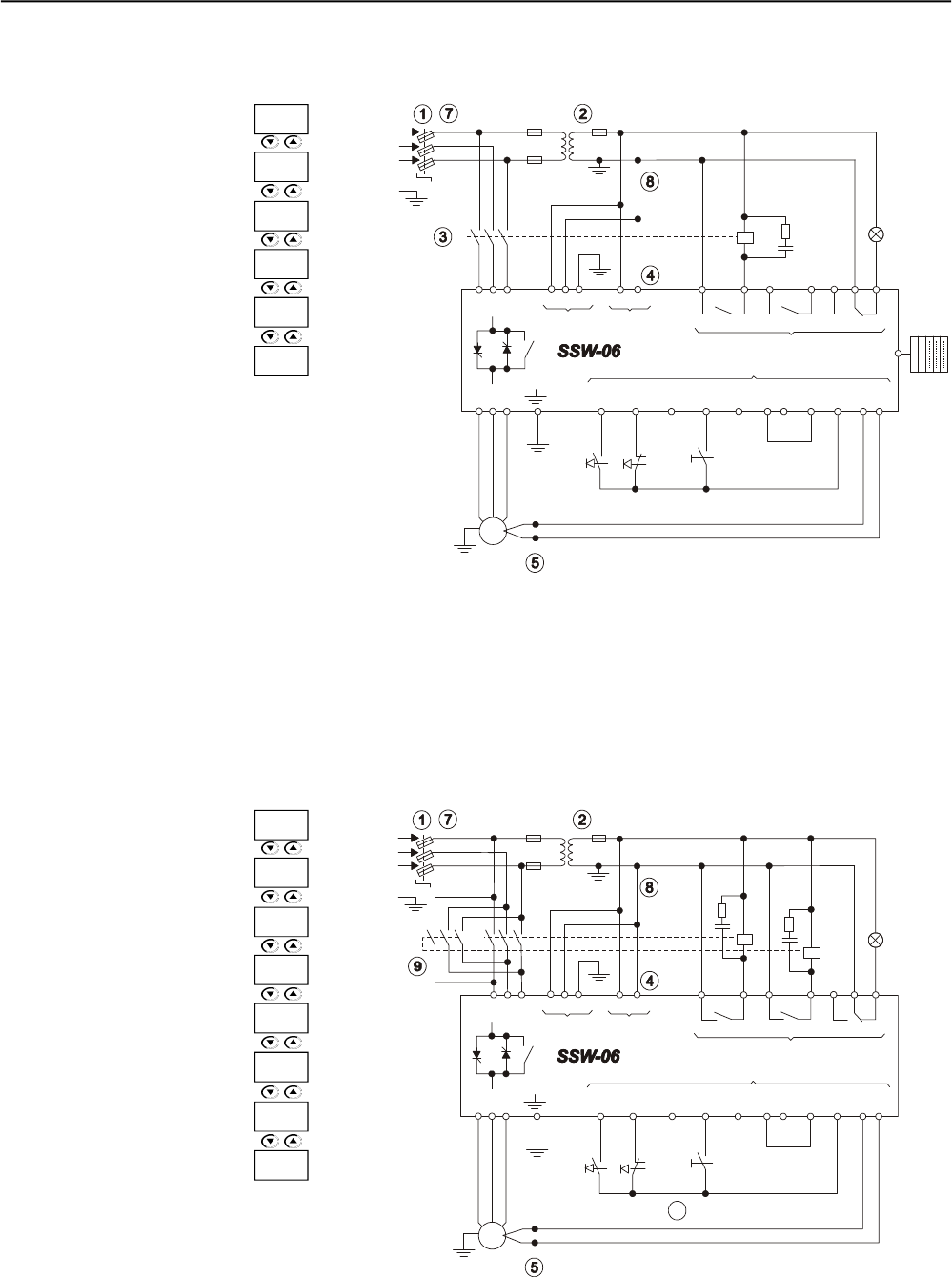
CHAPTER 3 - INSTALLATIONAND CONNECTION
53
3.3.7 Recommended Set-ups with Command via Three-wire Digital Input or Fieldbus
Communication.
Figure 3.28 - Recommended set-ups with command via three-wire digital input or fieldbus
communication
See note 3.3
+ to
M
3~
R
S
T
PE
K1
R S T 1 2 PE 33 34
X1EX1A
18 19
RL1 RL2
20 21 22 23 24
RL3
X1C
X1B
Dl1
3
Dl2
4
Dl3
5
Dl4
6
Dl5
7
COM
8 9
0V
10
24V
11
PTC
B A
12 13
U V W
Fault
T1
K1
PTC
X2
PLC
Local
Remote
Enable
Disable
3.3.8 Recommended Setup with Command via Digital Inputs and direction of rotation.
Figure 3.29 - Recommended Setup with Command via Digital Inputs and direction of rotation.
P264 =1
P230 =3
P229 =1
P220 =4
P277 =1
P279 =6
P264 =1
P231 =1
P230 =1
P220 =1
P266 =1
P277 =4
P278 =4
P279 =6
10
+ to
M
3~
R
S
T
PE
K1
R S T 1 2 PE 33 34
X1EX1A
18 19
RL1 RL2
20 21 22 23 24
RL3
X1C
X1B
Dl1
3
Dl2
4
Dl3
5
Dl4
6
Dl5
7
COM
8 9
0V
10
24V
11
PTC
B A
12 13
U V W
Fault
T1
K1
PTC
Enable
Disable
K2 K2
Direction of
Rotation
See note 3.3
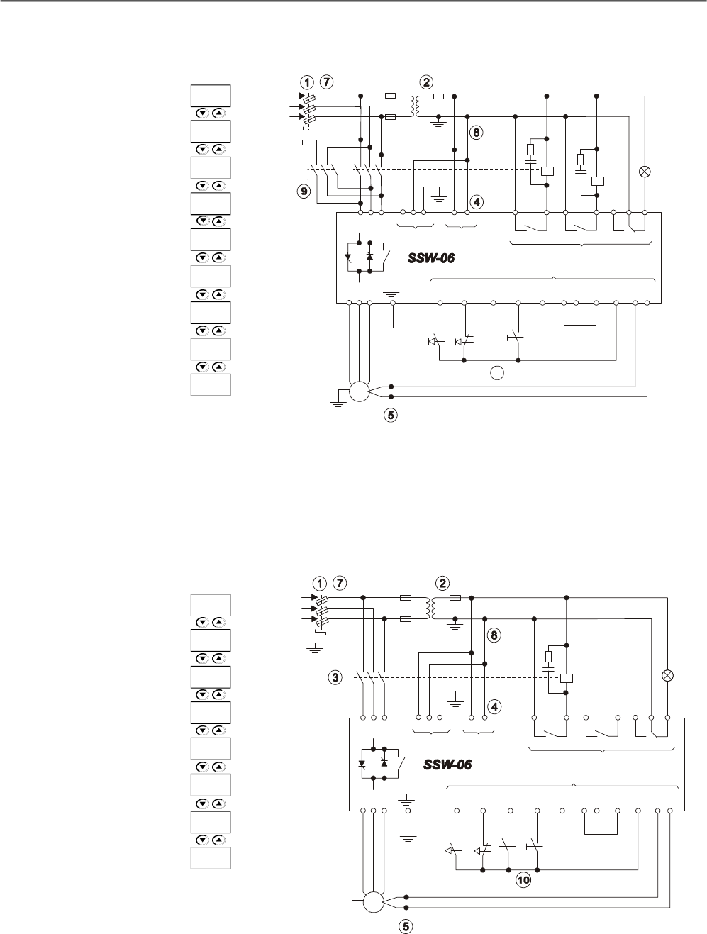
CHAPTER 3 - INSTALLATIONAND CONNECTION
54
3.3.9 Recommended Setup with Command via Digital Inputs and Reverse Braking
Figure 3.30 - Recommended Setup with Command via Digital Inputs and Reverse Braking.
3.3.10 Recommended Setup with Command via Digital Inputs and Optimal Braking
Figure 3.31 - Recommended Setup with Command via Digital Inputs and Optimal Braking.
P265 =1
P264 =1
P230 =1
P220 =1
P266 =5
P277 =4
P278 =4
P279 =6
P500 =1
P265 =1
P264 =1
P230 =1
P220 =1
P266 =5
P277 =1
P279 =6
P500 =2
10
+ to
M
3~
R
S
T
PE
K1
R S T 1 2 PE 33 34
X1EX1A
18 19
RL1 RL2
20 21 22 23 24
RL3
X1C
X1B
Dl1
3
Dl2
4
Dl3
5
Dl4
6
Dl5
7
COM
8 9
0V
10
24V
11
PTC
B A
12 13
U V W
Fault
T1
K1
PTC
Enable
Disable
K2 K2
Without
Braking
Gen. Enable
+ to
M
3~
R
S
T
PE
K1
R S T 1 2 PE 33 34
X1EX1A
18 19
RL1 RL2
20 21 22 23 24
RL3
X1C
X1B
Dl1
3
Dl2
4
Dl3
5
Dl4
6
Dl5
7
COM
8 9
0V
10
24V
11
PTC
B A
12 13
U V W
Fault
T1
K1
PTC
Enable
Disable
Without
Braking
Gen. Enable
See note 3.3
See note 3.3
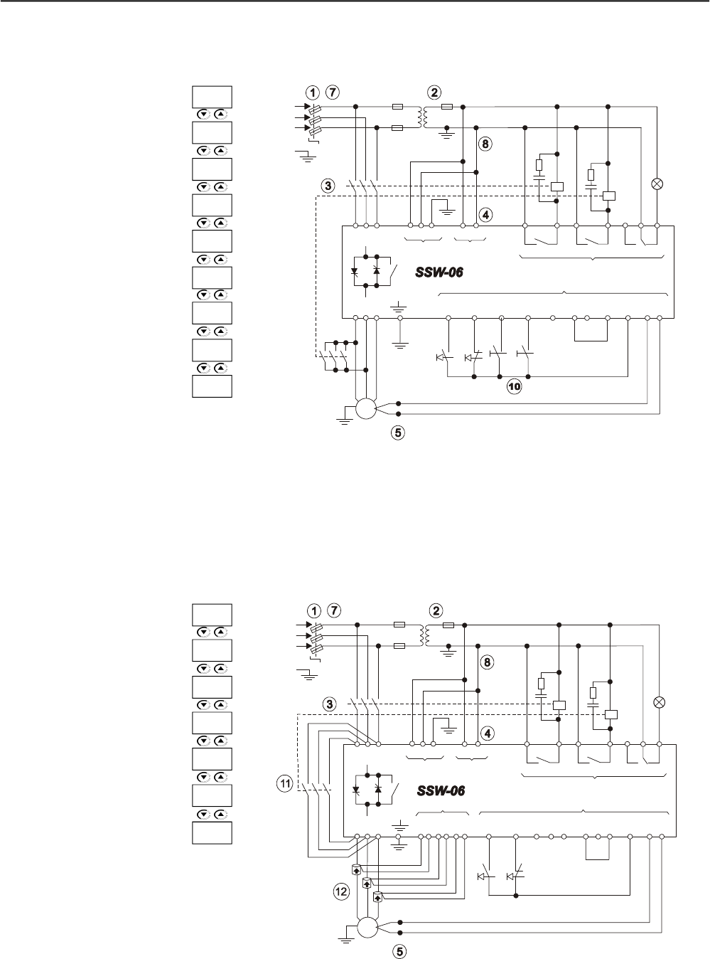
CHAPTER 3 - INSTALLATIONAND CONNECTION
55
3.3.11 Recommended Setup with Command via Digital Inputs and DC-Braking
Figure 3.32 - Recommended Setup with Command via Digital Inputs and DC-Braking.
3.3.12 Recommended Setup with Command via Digital Inputs and External By-pass Contactor
Figure 3.33 - Recommended Setup with Command via Digital Inputs and External By-pass
Contactor.
P265 =1
P264 =1
P230 =1
P220 =1
P266 =5
P277 =1
P279 =6
P500 =3
P278 =5
P264 =1
P230 =1
P220 =1
P140 =1
P277 =1
P278 =3
P279 =6
+ to
M
3~
R
S
T
PE
K1
R S T 1 2 PE 33 34
X1EX1A
18 19
RL1 RL2
20 21 22 23 24
RL3
X1C
X1B
Dl1
3
Dl2
4
Dl3
5
Dl4
6
Dl5
7
COM
8 9
0V
10
24V
11
PTC
B A
12 13
U V W
Fault
T1
K1
PTC
Enable
Disable
K2
Without
Braking
Gen. Enable
K2
+ to
M
3~
R
S
T
PE
K1
R S T 1 2 PE 33 34
X1EX1A
18 19
RL1 RL2
20 21 22 23 24
RL3
X1C
X1B
Dl1
3
Dl2
4
Dl3
5
Dl4
6
Dl5
7
COM
8 9
0V
10
24V
11
PTC
B A
12 13
U V W
Fault
T1
K1
PTC
Enable
Disable
K2
K2 X1D
27
28
29
30
31
32
Red
Black
Black
Red
Black
Red
See note 3.3
See note 3.3
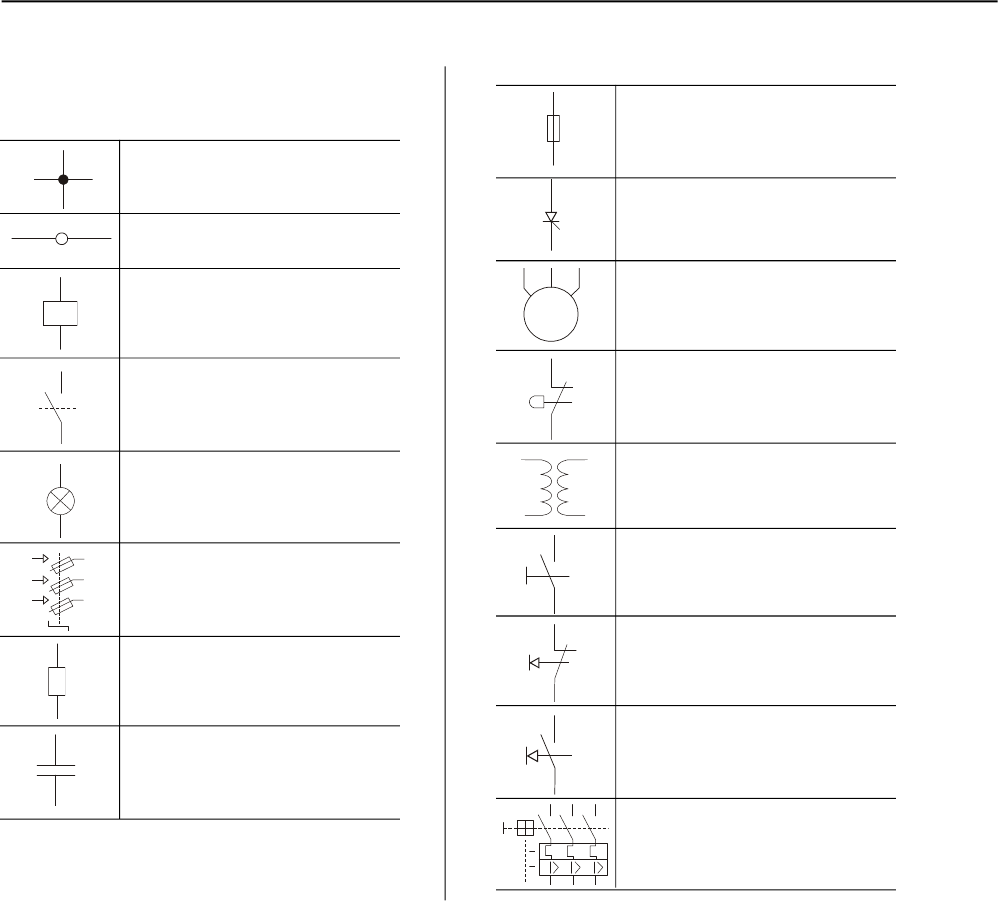
CHAPTER 3 - INSTALLATIONAND CONNECTION
56
Electrical connection between
two signal
Connection Terminals
Coil - Relay, Contactor
Normally Open Contact (NO)
Indicator light
Circuit-breaker
(opens under load)
Resistor
Capacitor
3.3.13Symbols
Fuse
Thyristor/SCR
Three-phase Motor
Emergency Button
Transformer
N.O. Contact (with retention)
Normally Closed (NC) Push-button
Normally Open (NO) Push-button
Circuit-breaker with under voltage
release
M
3~

CHAPTER 3 - INSTALLATIONAND CONNECTION
57
3.4.1 Installation
The SSW-06 series Soft-Starters were designed considering all the
safety and electromagnetic compatibility aspects.
SSW-06 Soft-Starters do not have any intrinsic function if they are not
connected to other components (for example, with a motor). For this
reason, the basic product does not have the CE label indicating
conformity with the electromagnetic compatibility directive.
The SSW-06 attends all the requirements of the electromagnetic
compatibility directive (89/336/EEC), as defined by Product Standard
EN60947-4-2 (2000) +A1 (2002) - “low-voltage switchgear and control-
gear part 4.2: Ac Semi-conductor Motor controllers and Starters” specific
standard for drives.
The conformity of all the SSW-06 series is based on tests of some
representative models. A Technical Construction File (TCF) was
checked and approved by a competent body.
3.4 European Directives for
Electromagnetic
Compatibility Requirements
for installation.
To install the Soft-Starter(s) in conformity with the EN60947-4-2 standard,
it is necessary to attend the following requirements:
1) The cables used for control (inputs and outputs) and signal wiring
must be armored or installed in metallic electroducts (conduits) or
in metallic channel with equivalent attenuation.
2) It is indispensable to follow the recommendations for earthing
presented in this manual.
3) Models 85A to 1400ASSW-06 Soft-Starters are classified for use in
“Class A”, individual use with no need of external filters or armored
power cables.
Description of the conducted emission classes according to
Standard EN60947-4-2 (2000) + A1 (2002):
- Class B: residential environment (first environment), unrestricted
distribution
- ClassA: industrial environment (second environment), unrestricted
distribution.
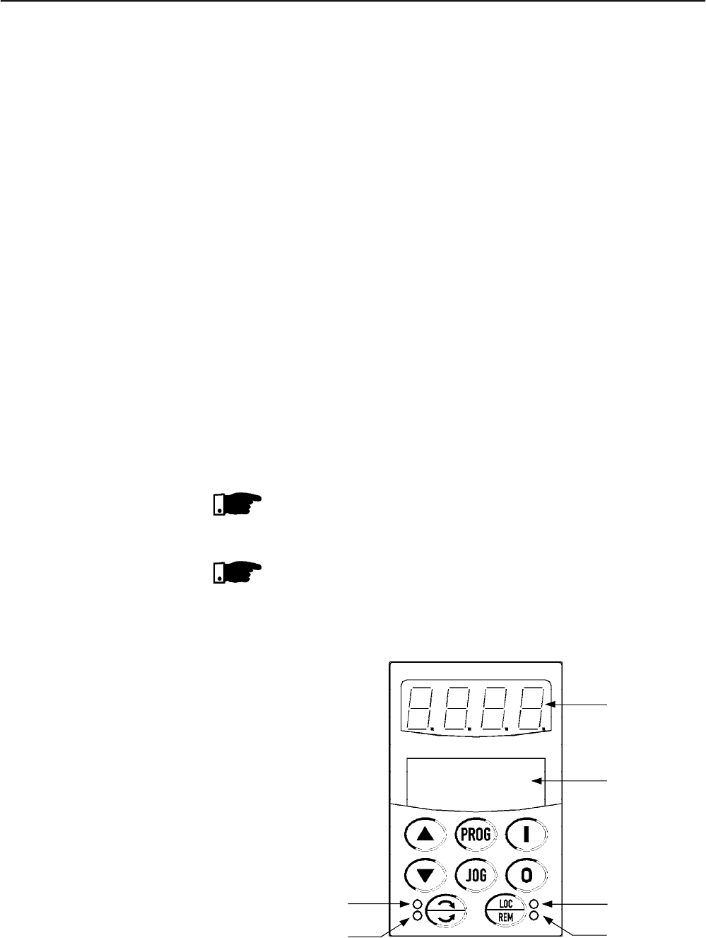
59
KEYPAD (HMI) OPERATION
This Chapter describes the operation of the standard Keypad (HMI) of
the Soft-Starter SSW-06, providing the following information:
General Keypad (HMI) Description;
Use of the Keypad;
Soft-Starter SSW-06 Parameters organization;
Parameter programming;
Description of the Status Indicators.
The standard Soft-Starter SSW-06 Keypad has one readout displays: a
LED readout with a 4 digit, seven-segment display and al LCD display
with two lines of 16 alphanumeric characters. There are also 4 indicator
LED’s and 8 keys.Figure 4.1 shows the front view of the Keypad and
indicates the position of the readouts, keys and status LED’s.
Functions of the LED Display:
Shows error and messages status (see Parameter, Error and State
Message Quick Reference), the parameter number or its context. The
unit display (to the right) indicates the unit of the indicated variable.
Acurrent
UVoltage
Hfrequency
Blankother parameters
NOTE!
When the indication is equal or higher than 1000 (A or U), the variable
unit will not be indicated (ex.: 568.A, 999.A, 1000,1023, etc.)
NOTE!
When the indication is higher than 9999 (inA, for instance), the number
corresponding to ten thousand will not be displayed (Ex.: 12345 A will
be read as 2345A).The correct indication will be displayed only on the
LCD display.
4.1 DESCRIPTION OF THE
KEYPAD (HMI-SSW06)
CHAPTER 4
Figure 4.1 - SSW-06 HMI
Green LED "Remote"
Green LED "Local"
LCD-Display
LED´s Display
Green LED "Forward"
Red LED "Reverse"
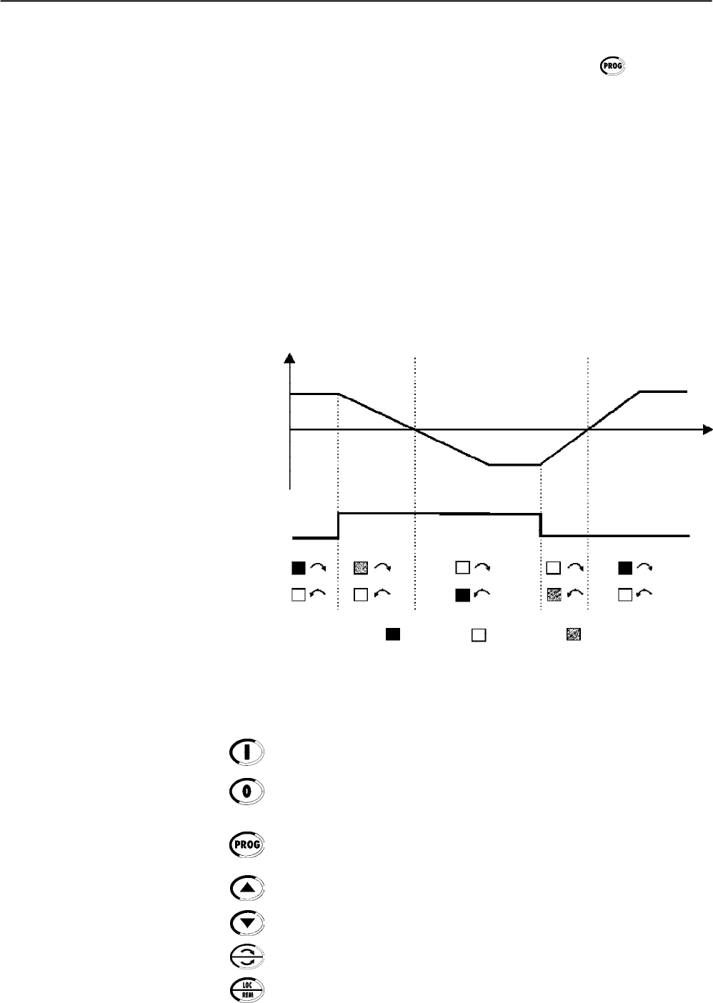
CHAPTER 4 - KEYPAD (HMI) OPERATION
60
Operation of the Man Machine Interface (MMI) keys:
Starts (Enable) the motor (start).
Stops (Disables) the motor (stop).
Also resets the Soft-Starter after a fault has occurred.
Toggles the LED displaybetween the parameter number and its value
(position/content).
Increases the number of the parameter or the value of the parameter.
Decreases the number of the parameter or the value of the parameter.
Reverses the direction of motor rotation between Forward/Reverse
Toggles between this LOCALor REMOTE modes of operation.
Functions of the LCD Display:
The LCD Display shows the parameter number and its value
simultaneously, without the need of pressing the key. It also
provides a brief description of each parameter and also the units
(A, Hz, V, s, %) when necessary. It also provides a brief description of
the fault code and inverter status.
Local and Remote Led Functions:
Soft-Starter in Local Mode:
Green Led on and Red Led Off.
Soft-Starter in Remote Mode:
Green Led Off and Red Led on.
Direction of Rotation (FWD/REV) LED Functions:
Not implemented in this Software Version
Speed
ON OFF FLASHING
Forward
Forward Reverse
Figure 4.2 - Direction of Rotation (FWD / REV) LED´s
0
FWD / REV Command (key)
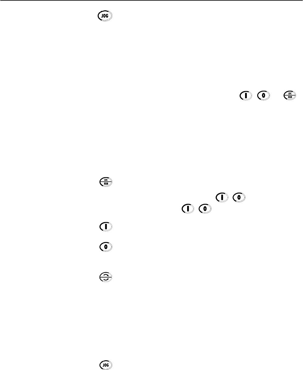
CHAPTER 4 - KEYPAD (HMI) OPERATION
61
The keypad is used for programming and operating the Soft-Starter
allowing the following functions:
Indication of the Soft-Starter SSW-06 status and main operation
variables;
Fault indications;
Viewing and programming of the setable parameters;
Soft-Starter SSW-06 operation (via keys , and ).
4.2 USE OF THE KEYPAD
4.2.1 Keypad use for
Soft-Starter SSW-06
Opertation
All functions relating to the Soft-Starter SSW-06 operation (Start, Stop,
Increment, Decrement, JOG- Local/Remote condition) can be performed
through the Keypad.Allkeypad keys are enabled when the Local Mode
has been selected. All these functions can be executed individually
through digital inputs. For this, all parameters related to these functions
and to the corresponding inputs must be programmed.
Operation of the Man Machine Interface (HMI) keys:
When programmed (P220 = 2 or 3), it selects the command source,
changing between "Local” and “Remote”.
When programmed (P229 = 0 (key , “ Local” condition)
and/or P230 = 0 ( key , “Remote condition”).
Starts the motor viaAcceleration Ramp. (motor accelerates according
to acceleration ramp and load characteristics).
Stops the motor via Deceleration Ramp. (motor decelerates according
to deceleration ramp and stops).
It resets the Soft-Starter after a fault trip (always active).
Reverses the motor direction of rotation.
Enabled when P220 = 2 (Keypad LOC), P229 = 0 (HMI Key), Local
Mode, P231 = 1 (By Contactor) or P231 = 2 (JOG Only).
Enabled when P220 = 3 (Keypad REM), P230 = 0 (HMI Key), Remote
Mode, P231 = 1 (By Contactor) or P231 = 2 (JOG Only).
When P231 = 1 (By Contactor), changes the motor direction of rotation
via contactor, if the contactors are connect at the input power supply
and P277 = 4 (FWD/REV-K1) and P278 = 4 (FWD/REV-K2).
When P231 = 2 (JOG Only), changes the motor direction of rotation
only to the Jog function. Contactors are not required.
Enabled when P510 = 1 (Active).
When the Jog key is pressed, it accelerates the motor to the Jog
frequencyconform the motor direction of rotation. When the Jog key is
released, the motor decelerates and stops.
When the Jog key is pressed, it accelerates the motor to the Jog
frequency according to the motor direction of rotation.
The motor must be disabled and the Soft-Starter SSW-06 is with Gene-
ral Enable.
Performs the JOG function when pressed. Any DIx programmed for
General Enable must be closed (and the SSW-06 must be stopped) to
enable JOG function.
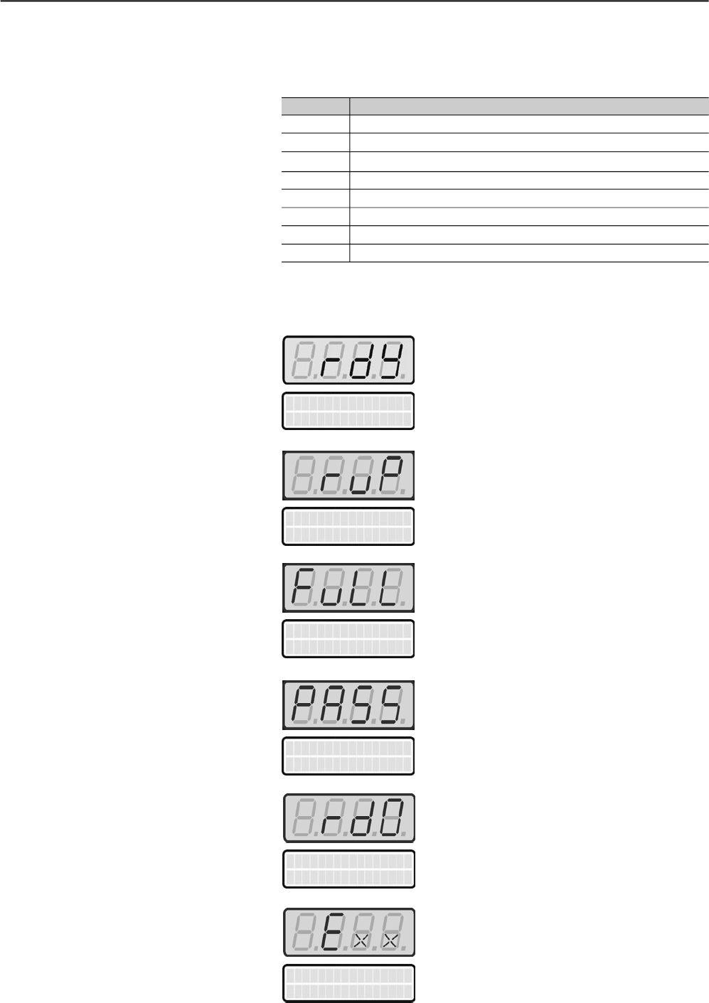
CHAPTER 4 - KEYPAD (HMI) OPERATION
62
SoftStarter
Ready
Soft-Starter Status:
Soft-Starter is ready to be enabled
Soft-Starter is operated via acceleration ramp
“ramp up”
Soft-Starter is operated at
“full voltage”
Soft-Starter is operated with enabled
By-pass.
SoftStart. Status
P006=ramp up
SoftStart. Status
P006=full voltage
SoftStart. Status
P006=bypass
Parameters P001 to P099 are onlyRead Parameters. The first parameter
to be displayed when the Soft-Starter is powered-up, can be programmed
at P205.
4.2.2 HMI Display - Signaling
indications
P205 Parameter to be displayed first
0 P001 (Motor current %In of the Soft-Starter)
1 P002 (Motor current %In of the Motor)
2 P003 (Motor current)
3 P004 (Line voltage)
4 P005 (Line Frequency)
5 P006 (Soft-Starter Status)
6 P007 (Output Voltage)
7 P008 (Power Factor)
Table 4.1 - Parameter initially shown in the displays
SoftStart. Status
P006=run down
Soft-Starter is operated via deceleration ramp
“ramp down”
Soft-Starter with fault
SoftStart. Status
P006=Exx
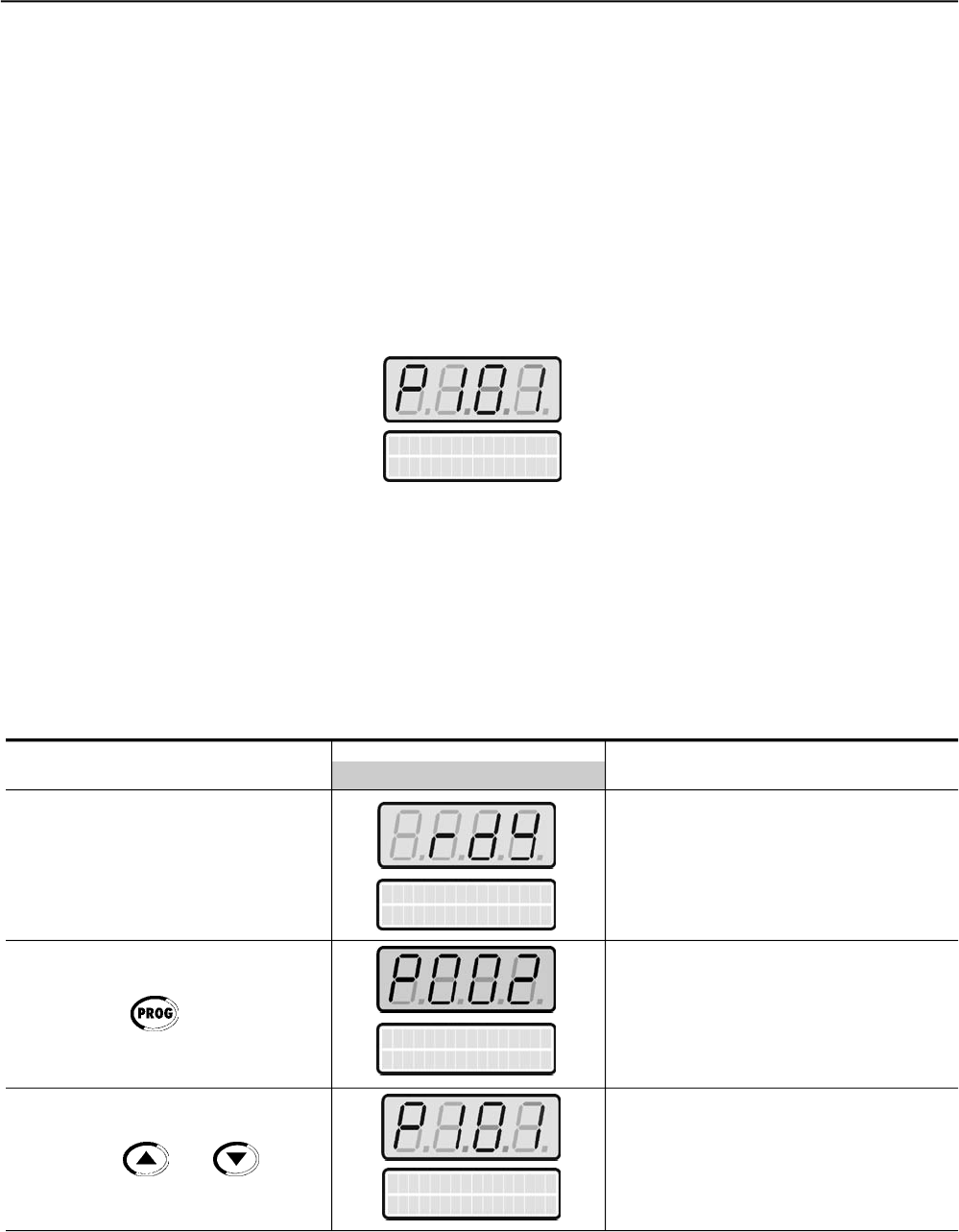
CHAPTER 4 - KEYPAD (HMI) OPERATION
63
7 Segment Display is flashing:
The display flashes in the following conditions:
trying to change a parameter value when it is not allowed;
Soft-Starter in Fault condition (Refer to Chapter 7 - Diagnosis and
Troubleshooting)
All Soft-Starter settings are made through the parameters. The
parameters are shown on the display with the letter Pfollowed by a
number:
Example (P101):
4.2.3 Parameter viewing and
programming
Init. Volt Start
P101=30%
101= Parameter Number
Each parameter is associated to a numerical value (parameter content),
that corresponds to an option selected among the options available for
this parameters.
The values of the parameters define the Soft-Starter programming or
the value of a variable (and.g. current, frequency, voltage). For Soft-
Starter programming you should change the parameter(s) content(s).
Press the key
Use the keys and
ACTION DISPLAY HMI LED DESCRIPTION
DISPLAY HMI LCD
SoftStarter
Ready
Motor Current
P000=0.0%
Init. Volt Start
P101=30%
Select the desired parameter
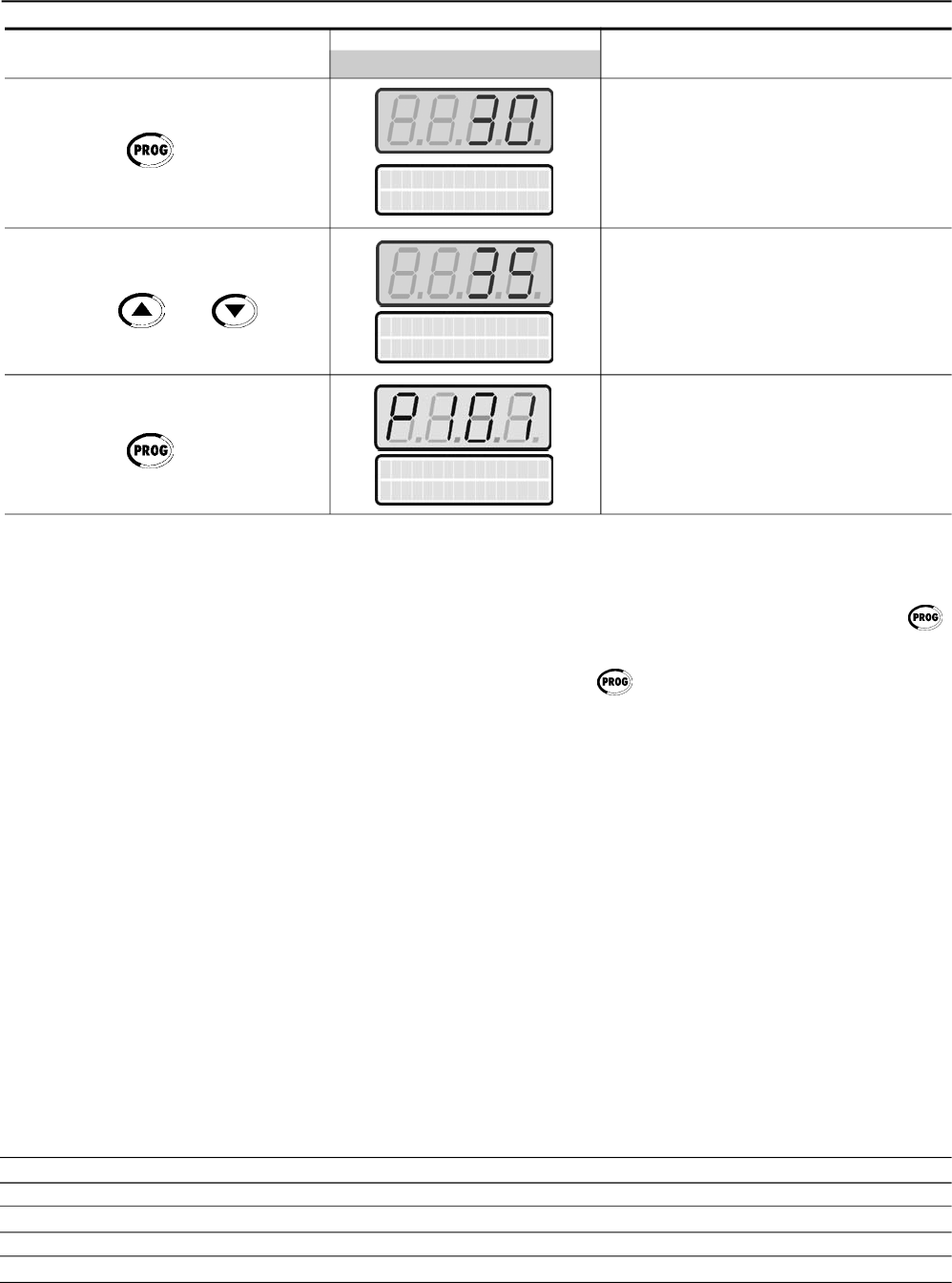
CHAPTER 4 - KEYPAD (HMI) OPERATION
64
Press the key
Use the keys and
Press the key
ACTION DISPLAY HMI LED DESCRIPTION
DISPLAY HMI LCD
Numeric value associated to the
parameter (4)
Sets the new desired value. (1) (4)
(1) (2) (3)
Init. Volt Start
P101=30%
Init. Volt Start
P101=35%
(1) For parameters that can be changed with the motor running, the
Soft-Starter will use the new value immediatelyafter it has been set.
For the parameters that can be changed onlywith the motor stopped,
the Soft-Starter will use this new set value only after the key
is pressed.
(2) By pressing the key after the reprogramming, the new
programmed value will be saved automaticallyand will remain stored
until a new value is programmed.
(3) If the last value programmed in the parameter is not functionally
compatible with other parameter values already programmed, an
E24 - Programming Error - will be displayed. Example of programming
error:
Programming two digital inputs (DIx) with the same function. Refer
to Table 4.2 for the list of programming errors that will generate an
E24 Programming Error.
(4) To allow the reprogramming of any parameter value it is necessary
to change parameterP000 to the password value. The factorydefault
password value is 5. Otherwise you can only read the parameter
values and not reprogram them.
For more details see P000 description in Chapter 6.
Two or more parameters between P266 and P268 equal to 1 (LOC/REM)
Two or more parameters between P266 and P268 equal to 2 (LOC/REM)
(P202 = 2 and P520 = 1) if there is pump control with kick start
(P202 = 3 and P520 = 1) if there is torque control with kick start
(P150 = 1 and P500 = 3) if there is DC-Braking with Delta Inside
Table 4.1 - Incompatibility between Parameters - E24
Init. Volt Start
P101=35%
E24 - Programming Error

65
The Soft-Starter SSW-06 shall be installed according to Chapter 3 -
Installation. If the drive project is different from the typical recommended
drives, the steps below may also followed.
DANGER!
Disconnect the AC input power before making any connections.
1) Check all connections:
Check if the power, grounding and control connections are correct
and well tightened.
2) Clean the inside of the Soft-Starter SSW-06:
Remove all shipping material from the inside of the Soft-Starter
SSW-06 or cabinet.
3) Checks the correct voltage selection:
In models 255A to 820A, the fan supply voltage selection is correct.
In models 950A to 1400A the single-phase supply voltage must be
checked to make sure it is adequate to the voltage of the fans.
4) Check the motor:
Check all motor connections and verify if their voltages, currents
and frequencies match the Soft-Starter SSW-06 specifications.
5) Check the Soft-Starter SSW-06 motor connection type:
Check if the standard three-wire connection should be used or if the
Soft-Starter SSW-06 should be connected via inside delta of the
motor. For more details, refer to Chapter 3.
6) Uncouple the load from the motor:
If the motor cannot be uncoupled, make sure that the direction of
rotation (FWD/REV) does cannot cause damage to the machine.
7) Close the Soft-Starter SSW-06 and/or cabinet cover.
START-UP
This Chapter provides the following information:
How to check and prepare the Soft-Starter SSW-06 before power-up;
How to power-up and check for proper operation;
Howto operate the Soft-Starter SSW-06 (See Electrical Installation).
5.1 POWER-UP
PREPARATION
CHAPTER 5
CHAPTER 5 - START-UP
66
5.2 INITIALPOWER-UP
(required parameter settings)
After the Soft-Starter SSW-06 has been checked, AC power can be
applied:
1) Check the supply voltage:
Measure the line voltage and check if it is within the specified range
(Rated Voltage - 15% to + 10% ).
2) Power-up the Electronics Supply:
NOTE!
Always energize the electronics supply before energizing the power
and execute all adjustments/settings described in this item.
3) Check if the power-up has been successful
When the Soft-Starter SSW-06 is powered up for the first time or
when the factory default parameter values are loaded (P204 = 5), a
start-up routine is run.
This routine requests the user to program some basic parameters
to ensure proper Soft-Starter SSW-06 and operation and motor
operation.This routine sequence changes according to the selected
type of control. For more details about the control type to be selected,
refer to Parameter P202 in Chapter 6.
The parameterization sequence for each control type is show in
figure 5.1.
ATTENTION!
For correct programming of the protection parameters, please consider
the catalog data and the motor nameplate data of the used motor.
To protect the motor against overloads during the start process and at
during operation, program the thermal class of the motor. For more
details about programming of the Thermal Class, see description of
Parameter P640 in Chapter 6.
In this parameter setting sequence only the main parameters for learning
about the Soft-Starter SSW-06 operation are shown. Please program
all necessary parameters for correct operation of the Soft-Starter and
motor protection, before operating it at rated operation conditions.
4) Close the input circuit-braker.
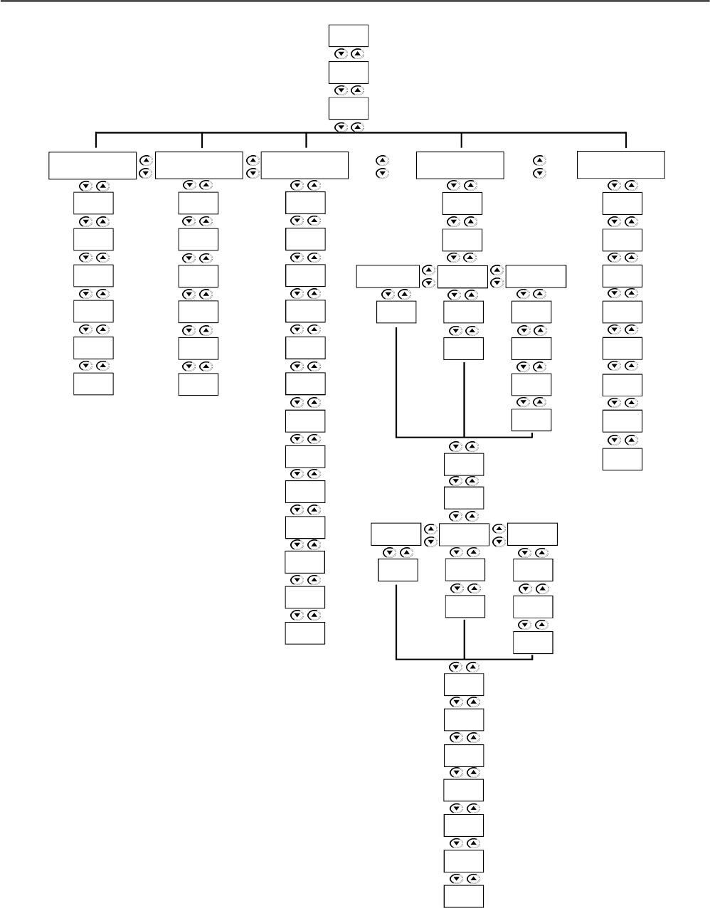
CHAPTER 5 - START-UP
67
Figure 5.1 – Parameter sequence during initial power-up
P611
P610
P401
P400
P102
P101
Voltage
Ramp
Current
Limit
P202
P150
P201
Pump
Control
P640
P406
P401
P400
P110
P102
P105
P104
P103
P102
P101
P130
P640
P406
P401
P400
P640
P406
P620
Torque
Control Current
Ramp
P120
P102
Constant Linear Square
P123
P122
P121
P122
P121P121
P124
Constant Linear Square
P128
P127
P126
P127
P126
P126
P402
P401
P400
P406
P405
P404
P640
P104
P125
P111
P110
P102
P112
P406
P401
P400
P640
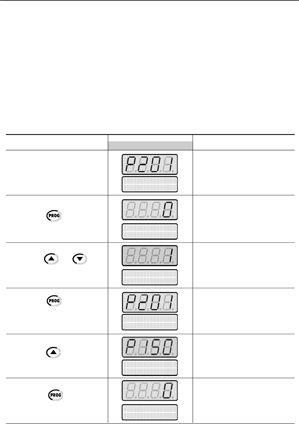
CHAPTER 5 - START-UP
68
Shown below is a parameter programming example requested by this
routine.
Example:
Soft-Starter SSW-06
SSW060130T2257PSZ
Motor
High Efficiency Plus Three-Phase Electric Motor- 4 Poles - 60Hz
Power: 75 HP
Frame size: 225S/M
Speed: 1770 rpm
Rated current at 380V: 101 A
Service Factor: 1.15
Start mode
Start-up by voltage ramp.
Initial Power-up - Programming via Keypad (HMI) (Based on the example above):
Language
P201 = Port
Language
P20 1 = Port
Language
P20 1 = English
Language
P20 1 = English
Delta Inside
P150=OFF
After Power-up, the Display shows
the following message
Press the key to enter the
programming mode
Use the keys and to
select the language
Press the key to save the
selected option and exit the
programming mode
Press the key to go to the
next parameter
Press the key to enter the
programming mode
ACTION HMI LED DISPLAY DESCRIPTION
HMI LCD DISPLAY
Language Selection:
0=Portuguese
1=English
2=Spanish
3=German
Enter the programming mode.
Selected language; English
Exit the programming mode.
Soft-Starter Connection Type to the
motor:
0=Inactive = standard 3 wires
1=Active = Delta inside 6 wires
Enter the programming mode
Delta Inside
P150=OFF
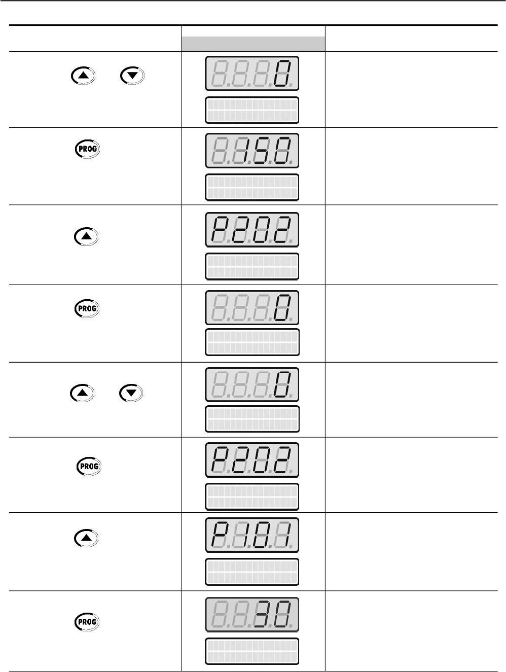
CHAPTER 5 - START-UP
69
Type of Control
P202= Volt.Ramp.
Type of Control
P20 2= Volt.Ramp.
Use the keys and for
programming Soft-Starter connection
type to motor
Press the key to save the
selected option and exit the
programming mode
Press the key to go to the next
parameter
Press the Key to enter the
programming mode
Use the keys and to
select the start control type
Press the key to save the
selected option and exit the
programming mode
Press the key to go to the next
parameter
Press the key to enter
programming mode
ACTION HMI LED DISPLAY DESCRIPTION
HMI LCD DISPLAY
Soft-Starter connection type to motor:
standard 3 wires
(Maintained the already existing
value)
Exit the programming mode
Selection of the start control type:
0=Voltage ramp
1=Current Limit
2=Pump Control
3=Torque Control
4=Current Ramp
Enter the programming mode.
Selected start control type:
Voltage ramp
(Maintained the already existing
value)
Exit the programming mode
Initial start voltage by voltage ramp:
(25 to 90)%Un
Enter the programming mode.
Delta Inside
P150=OFF
Delta Inside
P150=OFF
Type of Control
P20 2= Volt.Ramp.
Type of Control
P20 2= Volt.Ramp.
Init. Volt Start
P101=30%
Init. Volt Start
P101=30%
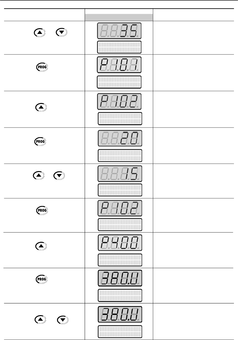
CHAPTER 5 - START-UP
70
Start Time Ramp
P102=20s
Start Time Ramp
P102=15s
Use the keys and to
select the initial start voltage
Press the key to save the
selected option and exit the
programming mode
Press the key to go to the next
parameter
Press the key to enter the
programming mode
Use the keys and to select
the ramp time for the start voltage
Press the key to save the
selected option and exit the
programming mode
Press the key to go to the next
parameter
Press the key to enter the
programming mode
Use the keys and to
select the motor rated voltage
ACTION HMI LED DISPLAY DESCRIPTION
HMI LCD DISPLAY
Init. Volt Start
P101=35%
Start Time Ramp
P102=20s
Start Time Ramp
P102=15s
Motor Rated Volt
P400=380V
Motor Rated Volt
P400=380V
Motor Rated Volt
P400=380V
Initial selected voltage:
35% Un
(according to load requirements)
Exit the programming mode
Voltage Ramp Time:
(1 to 999)s
Enter the programming mode.
Selected ramp time for the start
voltage: 15s
(according load requirements)
Exit the programming mode
Motor rated voltage (Un):
(0 to 999)V
Enter the programming mode.
Selected motor rated voltage:
380V
(according to the motor data)
Init. Volt Start
P101=35%
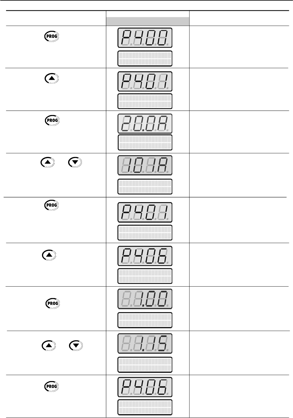
CHAPTER 5 - START-UP
71
ACTION HMI LED DISPLAY DESCRIPTION
HMI LCD DISPLAY
Motor Rated Cur.
P401=101.0A
Motor Rated Cur.
P401=101.0A
Press the key to save the
selected option and exit the
programming mode
Press the key to go to the next
parameter
Press the Key to enter the
programming mode
Use the keys and to
select the motor rated current
Press the key to save the
selected option and exit the
programming mode
Press the key to go to the next
parameter
Press the Key to enter the
programming mode
Use the keys and to
select the motor Service Factor
Press the key to save the
selected option and exit the
programming mode
Exit the programming mode
Motor Rated current (In):
(0 to 1500)A
Enter the programming mode.
Selected motor rated current:
101A
(according to the motor data)
Exit programming mode
Motor Service Factor (F.S.):
0.00 to 1.50
Enter the programming mode.
Selected motor Service factor:
1.15
(according to the motor data)
Exit programming mode
Motor Rated Cur.
P401=20.0A
Motor Rated Cur.
P401=20.0A
Service Factor
P406=1.00
Service Factor
P406=1.00
Service Factor
P406=1.15
Service Factor
P406=1.15
Motor Rated Volt
P400=380V
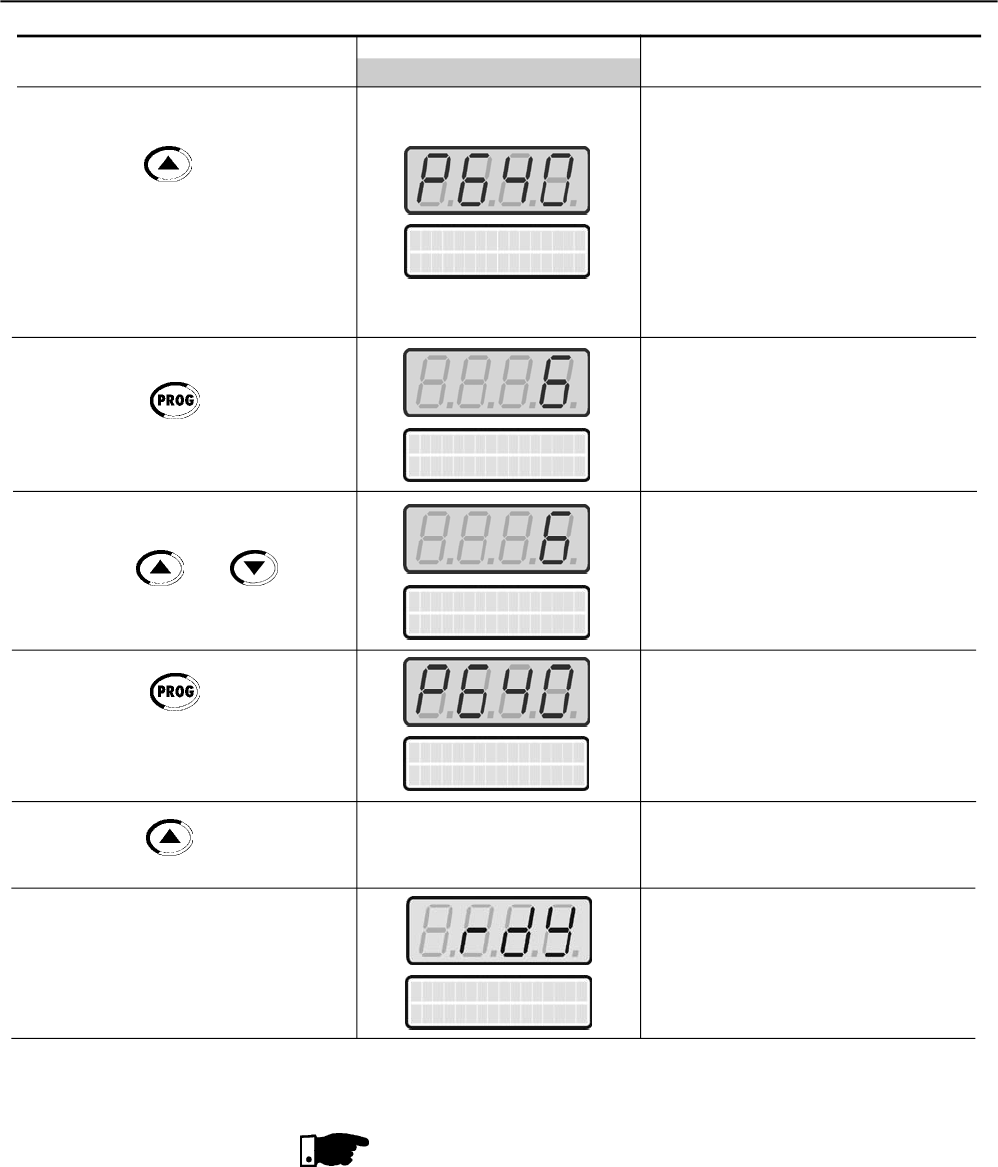
CHAPTER 5 - START-UP
72
Press the key to go to the next
parameter
Press the key to enter the
programming mode
Use the keys and to
select the thermal motor protection
class
Press the key to save the
selected option and exit the
programming mode
Press the key to go to the next
parameter
ACTION HMI LED DISPLAY DESCRIPTION
HMI LCD DISPLAY
Thermal motor Protection Class:
0= Inactive
1= Class 5
2= Class 10
4= Class 20
5= Class 25
6= Class 30
7= Class 35
8= Class 40
9= Class 45
Enter the programming mode.
Thermal motor protection class:
6= Class 30
(According to the motor data)
Exit the programming mode
Soft-Starter is reset
Soft-Starter is ready for operation
Soft Starter
ready
Open the input circuit-breaker to disconnect the Soft-Starter SSW-06.
NOTE!
Repeat the first power-up process:
If you want to repeat the first power-up routine, set parameter P204 = 5
(it loads the factory standard default parameters), then follow the first
power-up routine;
The first power-up routine, as decribed above, automatically sets some
parameters automatically to the factory default. For more details, refer
to Chapter 6.
Ther.Prot.Class
P640=Class 30
Ther.Prot.Class
P640=Class 30
Ther.Prot.Class
P640=Class 30
Ther.Prot.Class
P640=Class 30

CHAPTER 5 - START-UP
73
5.3 START-UP This Section describes the start-up procedure when operating via the
Keypad (HMI). Three types of control will be considered:
Start-up by Voltage Ramp:
The start by voltage ramp is the most used method and its programming
and parameter setting is very easy to do. The Soft-Starter SSW-06
applies the voltage to the motor without any feedback of the voltage or
current applied to the motor
Start-up by Current Limit:
The maximum current level is maintained during the start-up and it is
set according to the application requirements. This programming is
very easy.
Start-up by Current Ramp:
The maximum current level is also limited during the start-up, however
higher or lower start-up current limits can be set.
Start-up by Pump Control:
Optimized control method, providing the required torque to start/stop
hydraulic centrifugal pumps smoothly.
Start-up by Torque Control:
The Soft-Starter SSW-06 is fitted with a torque controlalgorithm of high
performance and is totally flexible to meet any application requirement
during the motor start or stop and its coupled load.
The method allows a torque control with 1 setting point, a torque control
with 2 setting points and a torque control with 3 setting points.
NOTE!
Every time the content of the Parameter P202 is changed, the Soft-
Starter will execute a setting sequence routine according to the selected
control type.
For more details, refer to Parameter P202 in Chapter 6 and 7.
The following sequence is valid for Drive 1 (see item 3.3.1). The SSW-06
Soft-Starter must already be installed and the electronics, fans and
power must already be energized, according to chapter 3, with the
setting sequence of the initial Start-up complete, as described
(Item 5.2).
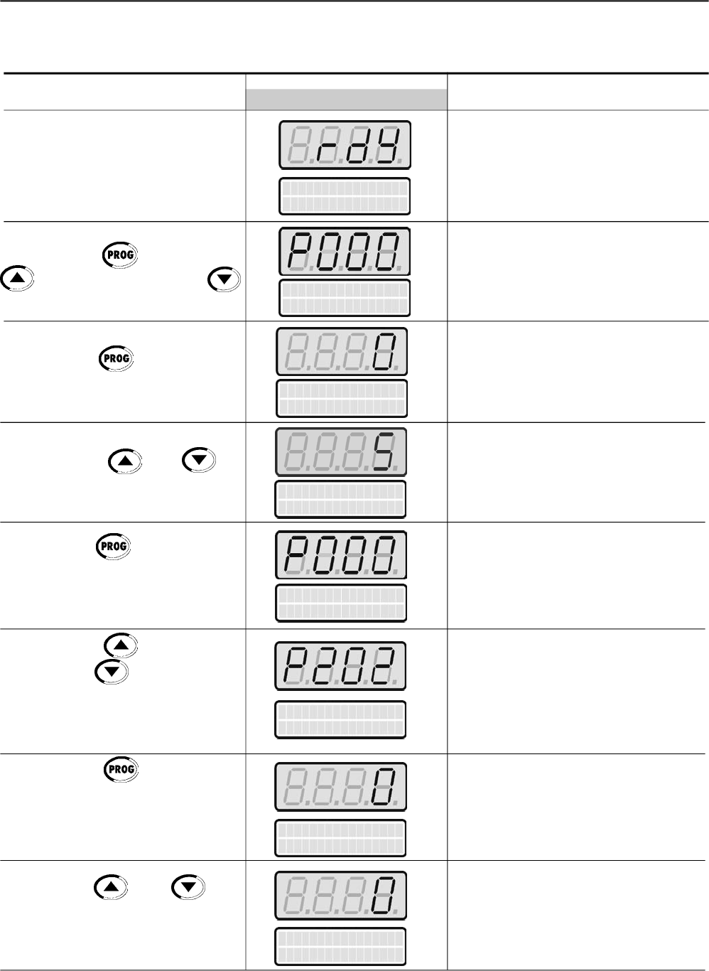
CHAPTER 5 - START-UP
74
5.3.1 Start -up: Operation via Keypad (HMI) Type of control: Voltage Ramp
Power-up the Soft-Starter
Press the key . Press the key
to find P000. Also the key
may be used to find Paramater P000
Press the key to enter the
programmin mode
Use the Keys and to
program the Password value
Press the key to save the
selected option and exit the
programming mode
Press the key to find P202.
Also the key may be used to
find Paramater P202
Press the Key to enter the
programming mode
Use the keys and to
select the correct value of the Control
Type
ACTION HMI LED DISPLAY DESCRIPTION
HMI LCD DISPLAY
Soft-Starter is ready to be operated
It enable the access for changing
parameter. With setting according to
Factory Default [P200 = 1 (Password is
active)], you must set P000 = 5 for
changing the parameter content.
Enter the Programming Mode
Password value
(Factory Default)
Exit the programming mode
This Parameter defines the Type of
Control
0=Voltage Ramp
1=Current Limit
2=Pump Control
3=Torque Control
4=Current Ramp
Enter the Programming Mode
Type of Control selected for the
Start-up: Voltage Ramp
(maintained the existing value)
Parameter Access
P000=0
Soft Starter
ready
Type of Control
P202=Volt. Ramp.
Parameter Access
P000=5
Parameter Access
P000=5
Type of Control
P202=Volt. Ramp.
Type of Control
P202=Volt. Ramp.
Parameter Access
P000=0
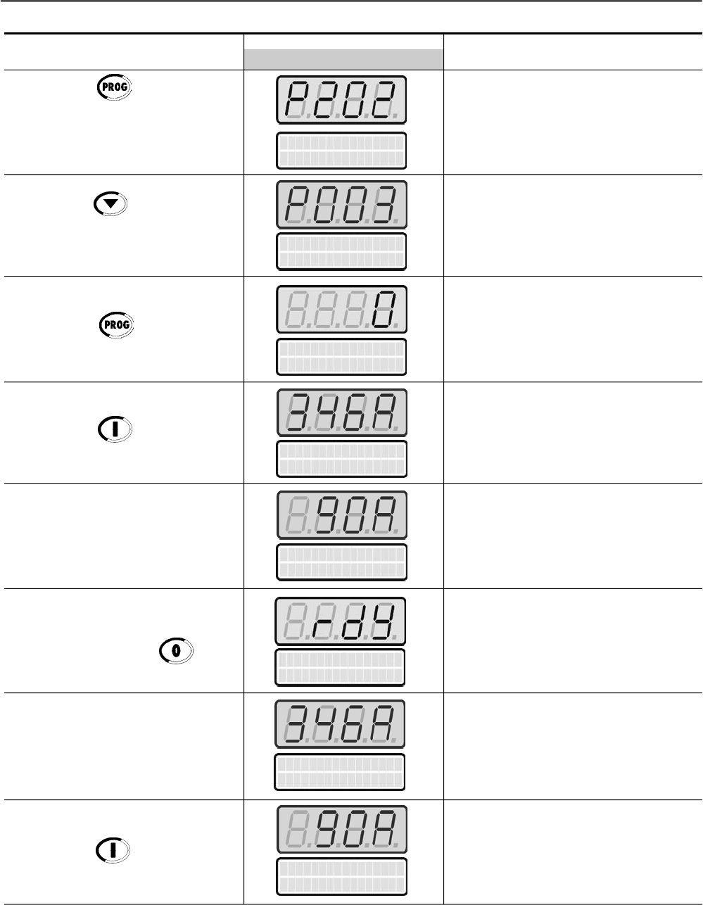
CHAPTER 5 - START-UP
75
Press the key to save the
selected option and exit the
programming mode
Press the key and maintain it
depressed to find P003
Press the key
Press the key
To Stop press the key
To restart press the key
Press the key
ACTION HMI LED DISPLAY DESCRIPTION
HMI LCD DISPLAY
Exit the programming mode
Motor Current (A)
This is only a Read Parameter
Motor accelerates and a high value of
current is reached.
Then the current decreases down to a
value required by the load.
Motor decelerates until stopping by
coast to rest. Time to stop depends on
load inertia and friction.
Motor accelerates and a high value of
current is reached.
Then the current decreases up to a
value required by the load.
Type of Control
P202=Volt. Ramp.
Motor Current
P003=0A
Motor Current
P003=0A
Motor Current
P003=90A
SoftStarter
ready
Motor Current
P003=346A
Motor Current
P003=90A
Motor Current
P003=346A
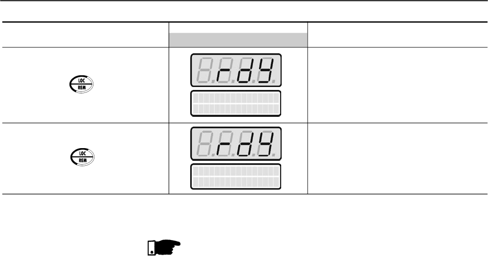
CHAPTER 5 - START-UP
76
Press the key again
ACTION HMI LED DISPLAY DESCRIPTION
HMI LCD DISPLAY
Soft-Starter is now controlled via
terminals (REMOTE). Motor
decelerates till stopping by the load
inertia.
Soft-Starter is controlled again via
keypad (LOCAL). Motor remains
stopped.
SoftStarter
ready
SoftStarter
ready
NOTES!
Setting hints and suggestions for all types of controls and their uses
can be found in Chapter 7.
For start-up through voltage ramp refer to Item 7.1.1.
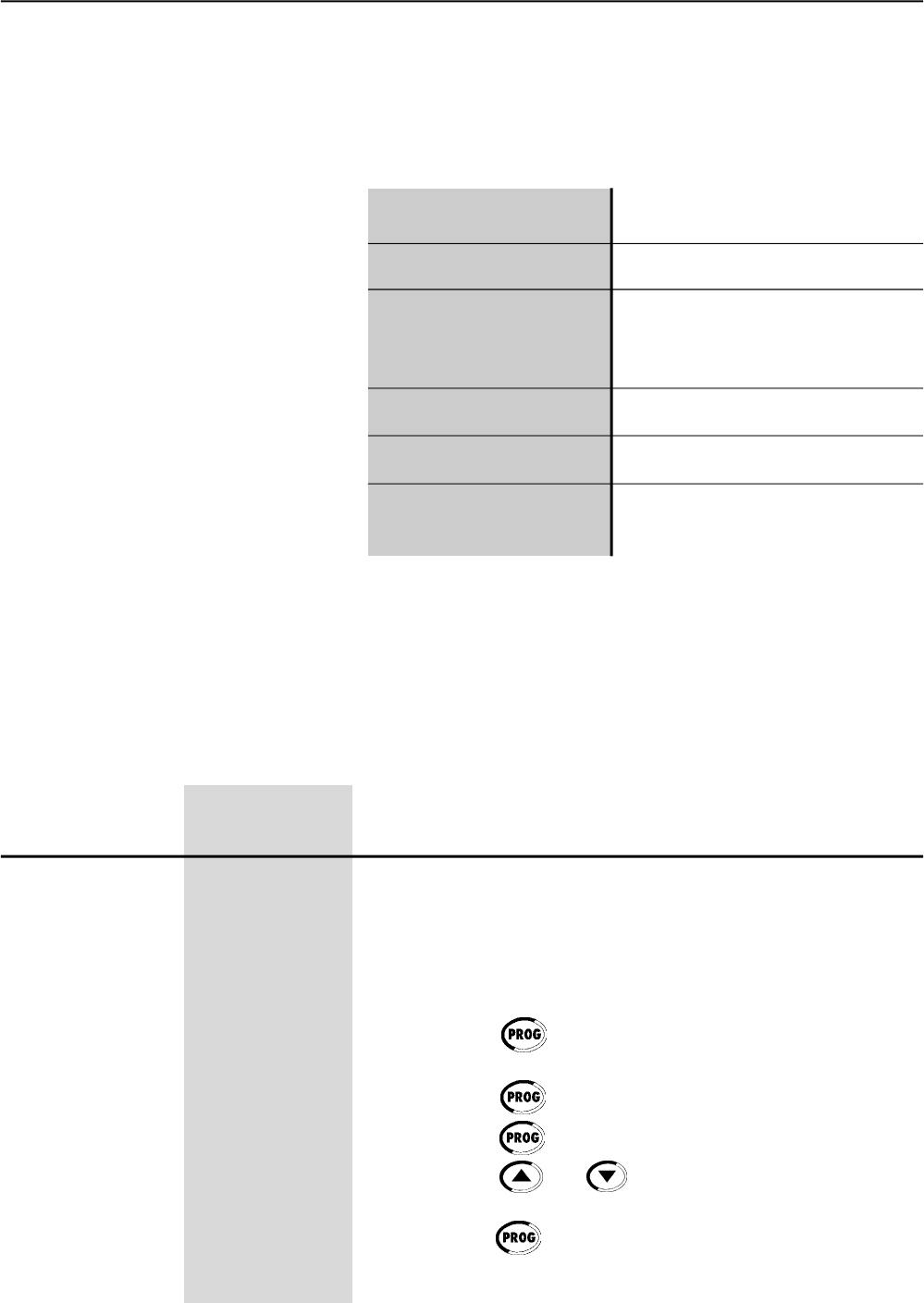
77
DETAILED PARAMETER DESCRIPTION
This Chapter describes in detail all Soft-Starter SSW-06 parameters. In
order to simplify the explanation, the parameters have been grouped by
characteristics and functions:
Symbols and definitions used in the text below:
(1) Indicates that the parameter can only be changed when the Soft-Starter
SSW-06 is disabled (motor stopped).
(2) Parameters not changed when programmed at Factory Default.
(P204=5).
6.1 ACCESS AND READ ONLY PARAMETERS - P000 to P099
This parameter opens the access to change the parameter values.
When values are set according to Factory Default [P200 = 1 (Password
is active)] to must set P000 = 5 to change parameter values, i. and.
the Password value is equal to 5.
To change the password to any other value (password 1), proceed as
follows:
(1) Set P000=5 (current password) and P200= 0 (password inactive).
(2) Press the key .
(3) Change P200 to 1 (password active).
(4) Press the key again: display shows: P000.
(5) Press the key again: display shows 5 (last password).
(6) Use the keys and to change to the desired password
value (password 1).
(7) Press the key : display shows P000. From this moment on, the
new password becomes active. Thus, to change parameter content
P000 one must set to the new password. (Password 1).
P000 0 to 999
Access Parameter/ [0]
Password Value -
Setting
Range
[Factory Setting]
Parameter Unit Description / Notes opens
Read Only Parameters Variables that can only be viewed on the
display but not changed by the user.
Regulation Parameters Programmable values used by the
Soft-Starter SSW-06 functions.
Configuration Parameters These Parameters define the Soft-Starter
SSW-06 characteristics, the functions
which to be executed, as well as the
input/output functions of the control board.
Motor Parameters Motor data that are indicated on the
motor nameplate.
Special Function Parameters Here are included the parameters
related to special functions.
Protection Parameters Here are included the parameters
related the actuation levels and
actuation time of the motor protection
CHAPTER 6

CHAPTER 6 - DETAILED PARAMETER DESCRIPTION
78
Indicates Soft-Starter SSW-06 output current as percentage of the
rated current of the Soft-Starter (%In of the SSW-06) .
Precision of ± 2% for the full scale. (The full scale is 5x ln of the
SSW-06).
NOTE!
When the connection is used inside the delta of the motor
(P150=1), the indication of the current value will already be
multiplied by 1.73.
P001 0 to 999.9
Soft- Starter SSW-06 [ - ]
Current 0.1%
Range
[Factory Setting]
Parameter Unit Description / Notes
Indicates Soft-Starter SSW-06 Output Current as percentage of the
motor rated current (%In of the motor).
Precision of ± 2% for the full scale. (The full scale is 5x ln of the
SSW-06).
NOTE!
When the connection is used inside the delta of the motor
(P150=1), the indication of the current value will already be
multiplied by 1.73.
P002 0 to 999.9
Motor Current [ - ]
0.1%
Indicates the Soft-Starter SSW-06 output current in Ampere (A).
Precision of ± 2% for the full scale. (The full scale is 5x ln of the
SSW-06).
NOTE!
When the connection is used inside the delta of the motor
(P150=1), the indication of the current value will already be
multiplied by 1.73.
P003 0 to 9999.9
Motor Current [ - ]
0.1A
Indicates the average True rms voltage of the tree input phases in
Volts (V).
Accuracy: ± 2V.
P004 0 to 999
Line Voltage [ - ]
1V
Indicates the line frequency in Hertz (Hz).
Precision of ± 5% of the rated frequency of the supply network.
NOTE!
Onlyindicates network frequency when there is a voltage greater
than 20V rms in the power supply (R/ 1L1, S/ 3L2 and T/5L3).
P005 0 to 99
Line Frequency [ - ]
1Hz
Indicates the actual Soft-Starter SSW-06 status:
0 = “rdy” Soft-Starter is ready to be enabled;
8 = “Sub” Soft-Starter under voltage fault;
9 = “Exx” Soft-Starter fault;
1 = “ruP” Soft-Starter is enabled according to “ramp up”;
2 = “FuLL” Soft-Starter is enabled at “full voltage”;
3 = “PASS“ Soft-Starter is enabled with “By-pass”;
6 = “ECO” Reserved;
4 = “rdo” Soft-Starter is enabled according to “ramp down”;
5 = “br” Soft-Starter is enabled according to “braking”;
6 = “rEv” Soft-Starter is enabled according to “reversing”;
7 = “JOG” Soft-Starter is enabled according to “jog”;
11 = “dly” Soft-Starter awaiting the post “delay” stop time;
12 = “G.di” Soft-Starter with “general disable”.
P006 XXXX
Soft-Starter SSW-06 [ - ]
Status -
CHAPTER 6 - DETAILED PARAMETER DESCRIPTION
79
Range
[Factory Setting]
Parameter Unit Description / Notes
Indicates motor power factor.
Accuracy::± 5%.
NOTE!
The motor power factor will only be indicated when the current is at
20% of the rated current of the SSW-06.
0.00 (Zero) will be indicated if the current is below 20% of the
SSW-06 rated current.
P008 0 to 1.00
Power Factor [ - ]
-
P009 0 to 999.9
Motor Torque [ - ]
0,1%
Indicates the motor torque in percent of the rated motor toque
(% Tn of the Motor).
The Soft-Starter SSW-06 is fitted with a software for estimating the
motor torque by using the same principles contained in Weg
Frequency Inverter
This high technology software enables indicating the motor torque
very close to the effective present torque.
Accuracy of ± 10% Tn of the Motor.
ATTENTION!
Information related to the rated torque of the motor and maximum
starting torque of the motor can be found in the manufacturer’s
catalogue.
NOTE!
Forthe correct torque to be indicated, in P009, all the parameters
related to the motor, P400 to P406, must be correctly programmed
according to the data informed in the motor name plate.
Indicates the active power as average of the three ouput phases of the
Soft-Starter SSW-06 in kilo Watts (kW).
NOTE!
The output power will only be indicated when the current is greater
than 20% of the SSW-06 rated current.
0 (Zero) Will be indicated if the current is lower than 20% of the
SSW-06 rated current.
P010 0 to 6553.5
Ouput Power [ - ]
0.1kW
Indicates the average True rms voltage of the tree output phases of
the Soft-Starter SSW-06 in Volts (V).
Accuracy: ± 2V.
P007 0 to 999
Soft-Starter SSW-06 [ - ]
Output Voltage 1V
Indicates the apparent power as average of the three ouput phases of
the Soft-Starter SSW-06 in kilo Volts Ampere (kVA).
P011 0 to 6553.5
Apparent Output [ - ]
Power 0.1kVA
CHAPTER 6 - DETAILED PARAMETER DESCRIPTION
80
Range
[Factory Setting]
Parameter Unit Description / Notes
RL1...RL3 Status
P012=101
DI1...DI6 Status
P012=100100
Indicates on the keypad LCD display the status of the 3 relay outputs
of the control board. Number 1 stands forActive and 0 for Inactive, in
the following order:
RL1, RL2, RL3.
The keypad LED display shows the decimal value that corresponds to
the status of the 3 digital outputs, where the status of each bit is
considered one bit in the specified sequence:
Inactive=0
Active=1
RL1 status is the most significant bit.
The 5 least significant bits are always ‘0’.
Example:
RL1=Active; RL2=Inactive; RL3=Active
This is equivalent to the binary sequence:
10100000
Which corresponds to the decimal number 160.
The least significant bits are not displayed.
The Keypad displays will be:
P013 LCD=1,0
Digital Outputs LED=0 to 255
RL1 to RL3 Status [ - ]
-
Indicates on the keypad LCD display the status of the 6 digital inputs
of the control board (DI1 to DI6). Number 1 stands forActive and Number
0 for Inactive, in the following order: DI1, DI2,...,DI5, DI6.
The LED Display shows a decimal value corresponding to the status
of the 6 digital inputs, where the status of each bit is considered one
bit in the specified sequence:
Inactive=0
Active=1
DI1 status is the most significant bit.
Example:
Dl1 = Active (+24V); Dl4 = Active (+24V);
Dl2 = Inactive (0V); Dl5 = Inactive (0V);
Dl3 = Inactive (0V); Dl6 = Inactive (0V).
It is equivalent to the bit sequence:
10010000
Which corresponds to the decimal number 144.
The least significant bits are not displayed.
The keypad displays will be as follows:
P012 LCD=1,0
Digital Input Status LED=0 to 255
DI1 to DI6 [ - ]
-
CHAPTER 6 - DETAILED PARAMETER DESCRIPTION
81
Range
[Factory Setting]
Parameter Unit Description / Notes
Indicates the Software Version contained in the microcontroller memory
of the control board.
P023 X.XX
Software Version [ - ]
-
Accuracy: ± 2% for full scale (full scale is 5 x In of the SSW-06).
NOTE!
When the connection is used inside the delta of the motor
(P150=1), the indication of the current value will already be
multiplied by 1.73.
P030 0 to 9999.9
Current of Phase R [ - ]
0.1A
P031 0 to 9999.9
Current of Phase S [ - ]
0.1A
P032 0 to 9999.9
Current of Phase T [ - ]
0.1A
P033 0 to 999
Line Voltage - R-S [ - ]
1V
P034 0 to 999
Line Voltage - S-T [ - ]
1V
P035 0 to 999
Line Voltage - T-R [ - ]
1V
Accuracy: ± 2V.
NOTE!
The voltage will onlybe indicated when it reaches a value greater
than 15V.
Below this value, only 0.00 (zero) will be indicated.
Indicate the code of the last, second, third and fourth previous Faults.
Fault Sequence:
Exy P014 P015 P016 P017
P014 03 to 77
Last Fault [ - ]
-
P015 03 to 77
Second Previous [ - ]
Fault -
P016 03 to 77
Third Previous [ - ]
Fault -
P017 03 to 77
Fourth Previous [ - ]
Fault -
Indicates the total number of hours that the Soft-Starter was powered.
The LED Display shows the total number of hours that the
Soft-Starter was energized divided by 10.
This value remains stored even when the Soft-Starter is switched OFF.
Example: Indication of 22 hours powered.
Time Powered
P042=22h
P042 LCD: 0 to 65530
Time Powered LED: 0 to 6553h(x10)
[ - ]
1h
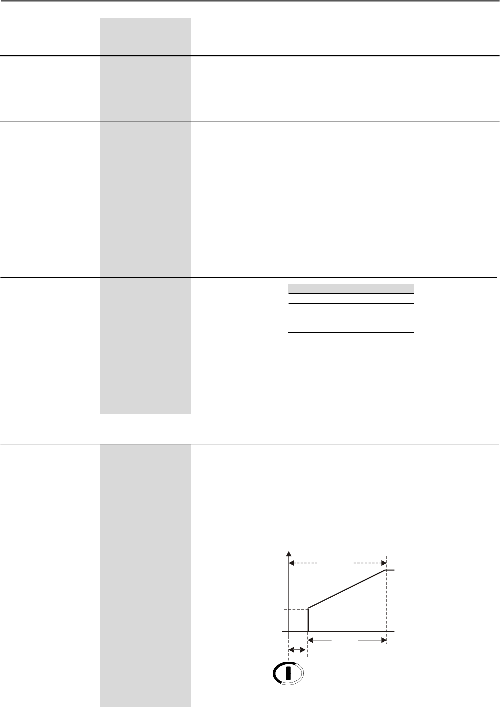
CHAPTER 6 - DETAILED PARAMETER DESCRIPTION
82
Range
[Factory Setting]
Parameter Unit Description / Notes
Indication of the state of motor thermal protection in a scale of 0% to
250%. Being 250 the thermal protection functioning point of the mo-
tor, indicating an error.
The value indicated in this parameter depends on the motor working
condition and how long it has been in this condition, for example:
stopped, starting or in full operation.
The thermal class selected and the rated power of the motor also
influence in this parameter.
Only a value of approximately 160 can be read if the motor is operating
in full load for over 2 hours with a current equal to the rated current
plus the service factor (In x F.S. @ 2h).
P050 0 to 250
Motor Thermal [ - ]
Protection Status 1%
P085 0 to 3
Status of the Fieldbus [ - ]
Communication Board -
P085 Description
0 Off
1 Board inactive
2 Board active and Offline
3 Board active and Online
Indicates the status of the Fieldbus communication board.
Standard is disabled when board is not inserted.
For more details, refer to the Fieldbus Manual for the Soft-Starter
SSW-06.
Table 6.1 - Fieldbus communication board status
6.2 REGULATION PARAMETERS - P100 to P199
Used in the control byVoltageRamp and Pump Controls, P202=0 or 2.
Sets the initial value of the rated voltage (%Un) that will be applied to
the motor according to Figure 6.1.
For more details about the programming and use, see Voltage Ramp
and Pump Control in P202.
The initial voltage is 0.5s after the Soft-Starter SSW-06 receives the
command to start the motor. This is the waiting time for the network
isolation contactor to start the power supply.
P101
Initial Voltage 25 to 90
[ 30 ]
1% Un of the Motor
P043 0 to 6553
Time Enabled [ - ]
0.1 (<999.9)
1 (<6553)
Indicates the total number of hours that the Soft-Starter has run.
This value remains stored even when the Soft-Starter is turned OFF.
Indicates up to 6553 hours, rolls over to 0000.
If P204 is set to 3, P043 is reset to zero.
Start
P102
0,5s
0
P101
U(V)
Start
Figure 6.1 – Initial time for motor start
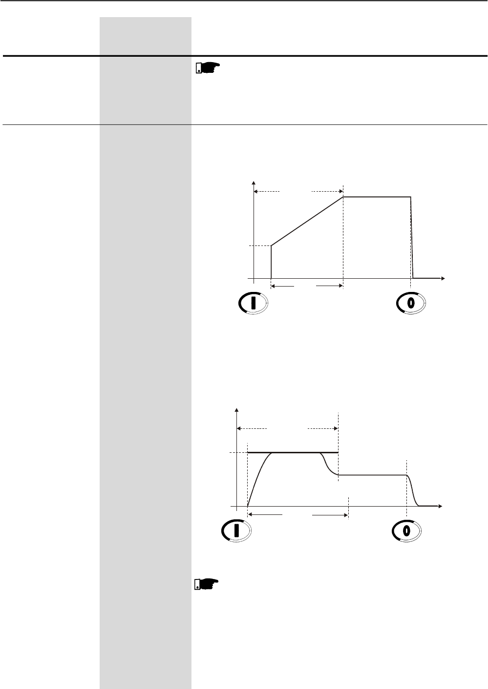
CHAPTER 6 - DETAILED PARAMETER DESCRIPTION
83
Range
[Factory Setting]
Parameter Unit Description / Notes
P102 1 to 999
Acceleration [ 20 ]
Ramp Time 1s
When the Soft-Starter SSW-06 has been programmed to Voltage
Ramp Control or Pump Control, this will be the ramp time of the
voltage increment as shown in Figure 6.2.
Figure 6.2 – Acceleration ramp by Voltage Ramp
When the Soft-Starter SSW-06 has been programmed to Current
Limit control, Torque Control or Current Ramp, this time acts as
maximum starting time, as a protection against locked rotor.
NOTE!
When another control type is selected, not the Voltage Ramp
or Pump Control, the initial voltage will be attenuated due to the
limit imposed by the current.
Figure 6.3 – Acceleration Ramp by Current Limit
NOTE!
The time set at P102 is not the exact motor acceleration time,
but the voltage ramp time or the maximum start time. The motor
acceleration time will depend on the motor and the load
characteristics.
Start
P102
0
P101
U(V) 100%Un
t(s)
DisableEnable Voltage Ramp
Start
P102
0
P110
I(A)
I Limit
t(s)
DisableEnable Current Limit
Rated Current
Maximum time
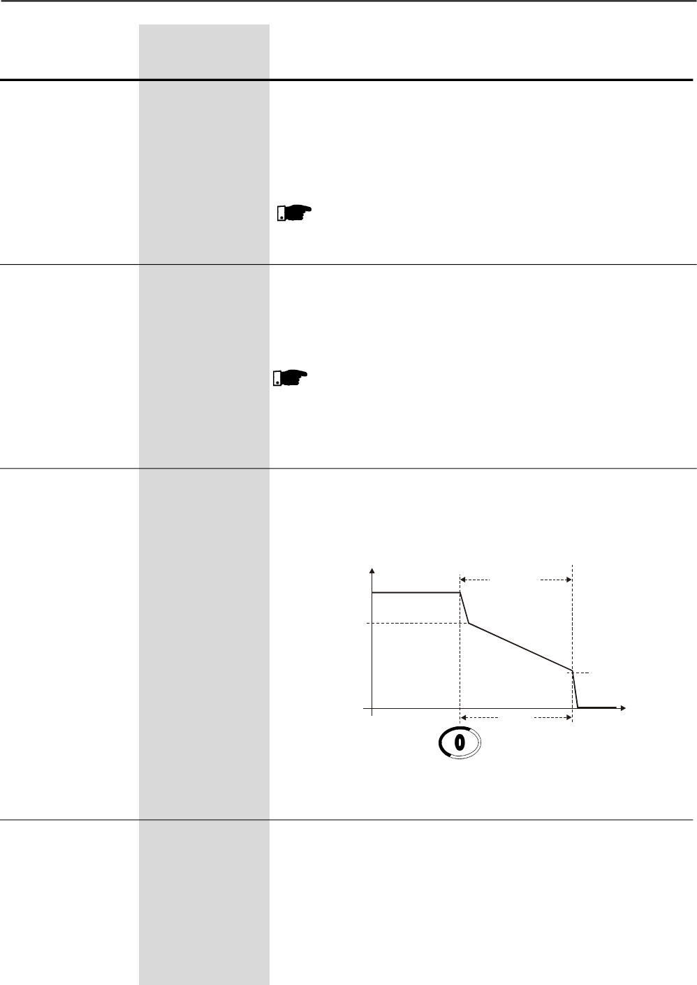
CHAPTER 6 - DETAILED PARAMETER DESCRIPTION
84
Range
[Factory Setting]
Parameter Unit Description / Notes
P104 1 to 299
Deceleration [ 0=Inactive ]
Ramp Time 1s
Used in hydraulic pump applications.
Enables and sets the time of the voltage decrement ramp.
For more details about programming and use, refer to Pump Control.
It can be used as Voltage Ramp control, Pump Control, Current Limit
and Current Ramp.
NOTE!
This function is used to lengthen the normal deceleration time of
a load and not to force a shorter time than that imposed by the
load.
P105 30 to 55
End Deceleration [ 30 ]
Voltage -
Used in hydraulic pump applications.
Sets the rated voltage (%Un), which will be applied to the motor at
the end of the deceleration ramp.
For more details about the programming and use, refer to Pump
Control.
P103 99 to 60
Voltage Step [ 100=Inactive ]
during Deceleration 1% Un of the Motor
Used in applications with hydraulic pumps.
Set the rated voltage (%Un), which will be applied to the motor
instantaneously when the Soft-Starter SSW-06 receives the ramp
deceleration command.
For more details about programming and use, refer to Pump Control
at P202.
NOTE!
To enable this function, you must set a deceleration ramp time.
Figure 6.4 – Deceleration Ramp by voltage decrement
100%Un
P104
0
U(V) Stop
t(s)
Disable Voltage Ramp
P103
P105
P110 150 to 500
Current Limit [ 300% ]
1% In of the Motor
Defines the current limit during the motor start as a percentage of
the rated motor current set at P401.
When the current limit is reached during the motor start, the
Soft-Starter SSW-06 will maintain the current at this limit until the
motor reaches the end of the start.
When the current limit is not reached, themotor will start immediately.
For more information about selection of the Current Limit control,
refer to P202.
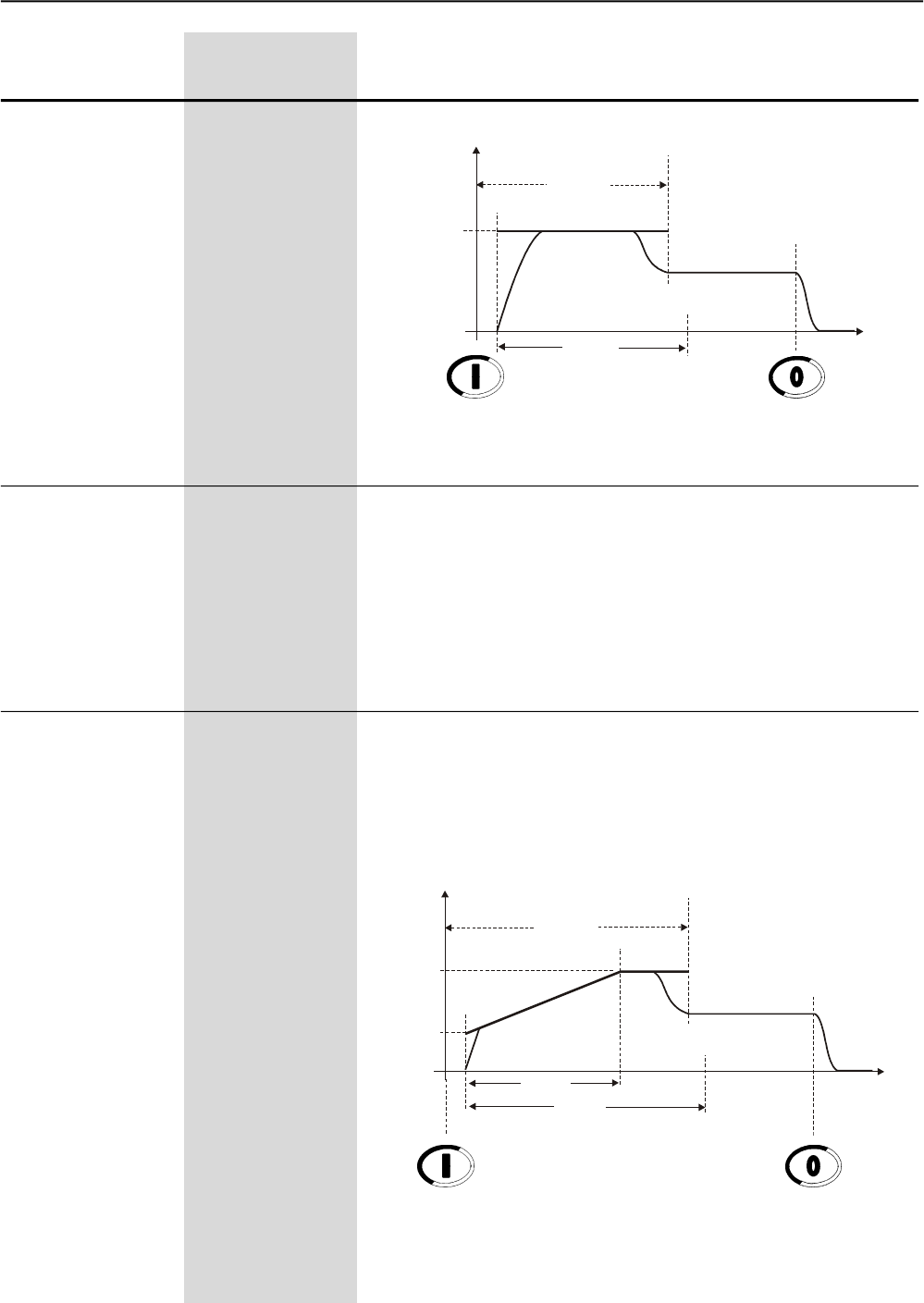
CHAPTER 6 - DETAILED PARAMETER DESCRIPTION
85
Range
[Factory Setting]
Parameter Unit Description / Notes
Figure 6.5 – Fixed starting Current Limit
P111 150 to 500
Initial Current by [ 150 ]
Current Ramp 1% Un of the Motor
Used for the control by Current Ramp, P202=4.
Allows a current limit ramp to be programmed to help in the starting
of loads that have a lower or higher starting torque.
The initial value of the current limit is shown by P111, the final value
is shown by P110 and the time is shown by P112, according to figure
6.6.
P112 1 to 99
Time for Current [ 20 ]
Ramp 1% of P102
Used for the control by Current Ramp, P202=4.
It enables programming the time, in percent of P102, for the end
Current Ramp.
After the time, programmed at P112, has elapsed, it starts operation
by Current Limit, given by P110.
Start
P102
0
P110
I(A)
t(s)
DisableEnable Current Limit
I Limit
Rated Current
Maximum Time
a)
Start
P102
0
P110
I(A)
t(s)
DisableEnable Current Limit
I Limit Rated Current
P111
P112
Maximum Time
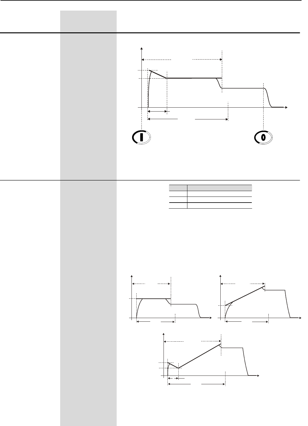
CHAPTER 6 - DETAILED PARAMETER DESCRIPTION
86
Range
[Factory Setting]
Parameter Unit Description / Notes
Figure 6.6 a) and b) - Current Limit by Current Ramp during Starting
P120(1) 1 to 3
Starting Torque [ 1=Constant ]
Characteristics -
P120 Starting Torque Profile
1 Constant (1 setting point)
2 Linear (2 setting points)
3 Quadratic (3 setting points)
It enables choosing which torque limit profile the Soft-Starter SSW-06
will supply to the motor during the start.
Three different types of Torque Limit Profile are available allowing the
start of any type of load: constant or 1 point, linear or 2 points and
quadratic or 3 points.
Figure 6.7 a) to c) - Available Torque Profile during the start
Table 6.2 - Starting Torque Profile
b)
Tn(%)
P121
Start
P202=1
P102
0
Tn Nominal
Tn(%)
P121
0
t(s) P102 t(s)
P202=2
Tn Nominal
Start P122
Tn(%)
P121
0
P102
t(s)
P202=3
Tn Nominal
Start P122
P123
P124
a) b)
c)
Start
P102
0
P111
I(A)
Rated Current
t(s)
DisableEnable Current Limit
P110
P112
I Limit
Maximum Time
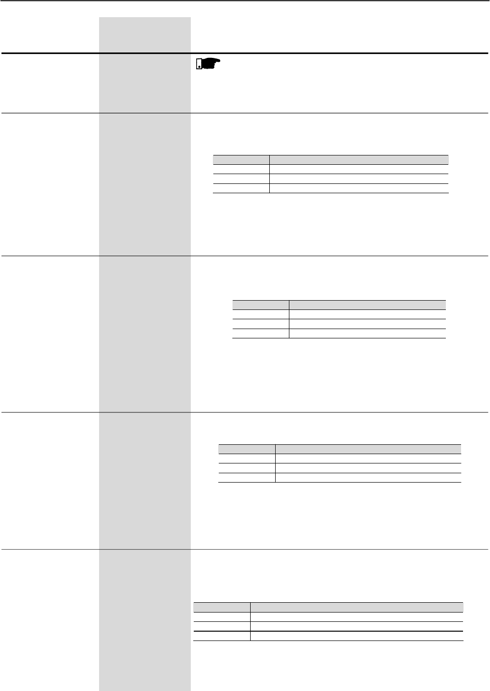
CHAPTER 6 - DETAILED PARAMETER DESCRIPTION
87
Range
[Factory Setting]
Parameter Unit Description / Notes
NOTE!
Choose the type of torque control, easier to program and set,
according to the knowledge about the characteristics of the load.
P121 10 to 400
Initial Starting [ 30 ]
Torque 1% Tn of the Motor
Enables programming an initial torque limit or a constant during the
start, according to the torque type selected at P120.
P120 Action
1 (Constant) P121 limits the maximum torque during the start.
2 (Linear) P121 limits the initial torque during the start.
3 (Quadratic) P121 limits the initial torque during the start.
For more details about programming and application, refer to Torque
Control at P202.
P122 10 to 400
End Satrting [ 110 ]
Torque 1% Tn of the Motor
It enables programming an end torque limit for the start, when a
linear or quadratic torque linear has been selected at P120.
P122 Action
1 (Constant) P122 Not used
2 (Linear) P122 limits the end torque during the start.
3 (Quadratic) P122 limits the end torque during the start.
For more details about programming and application, refer to Torque
Control at P202.
P123 10 to 400
Minimum Starting [ 27 ]
Torque 1% Tn of the Motor
It enables programming an intermediate torque limit during the start,
when a quadratic torque ha been selected at P120.
P123 Action
1 (Constant) P123 not used
2 (Linear) P123 not used
3 (Quadratic) P123 limits the intermediate torque during the start.
For more details about programming and application, refer to Torque
Control at P202.
P124 1 to 99
Time for Minimum [ 20 ]
Starting Torque 1% of P102
It enables programming the time for the intermediate torque limit
during the start, as a percentage of the maximum time programmed
at P102, when a quadratic torque has been set at P120.
P124 Action
1 (Constant) P124 not used
2 (Linear) P124 not used
3 (Quadratic) P124 time for the intermediate torque limit during the start.
For more details about programming and application, refer to Torque
Control at P202.
Table 6.3 - Function of P121 according to P120
Table 6.4 - Function of P122 according to P120
Table 6.5 - Function of P123 according to P120
Table 6.6 - Function of P124 according to P120
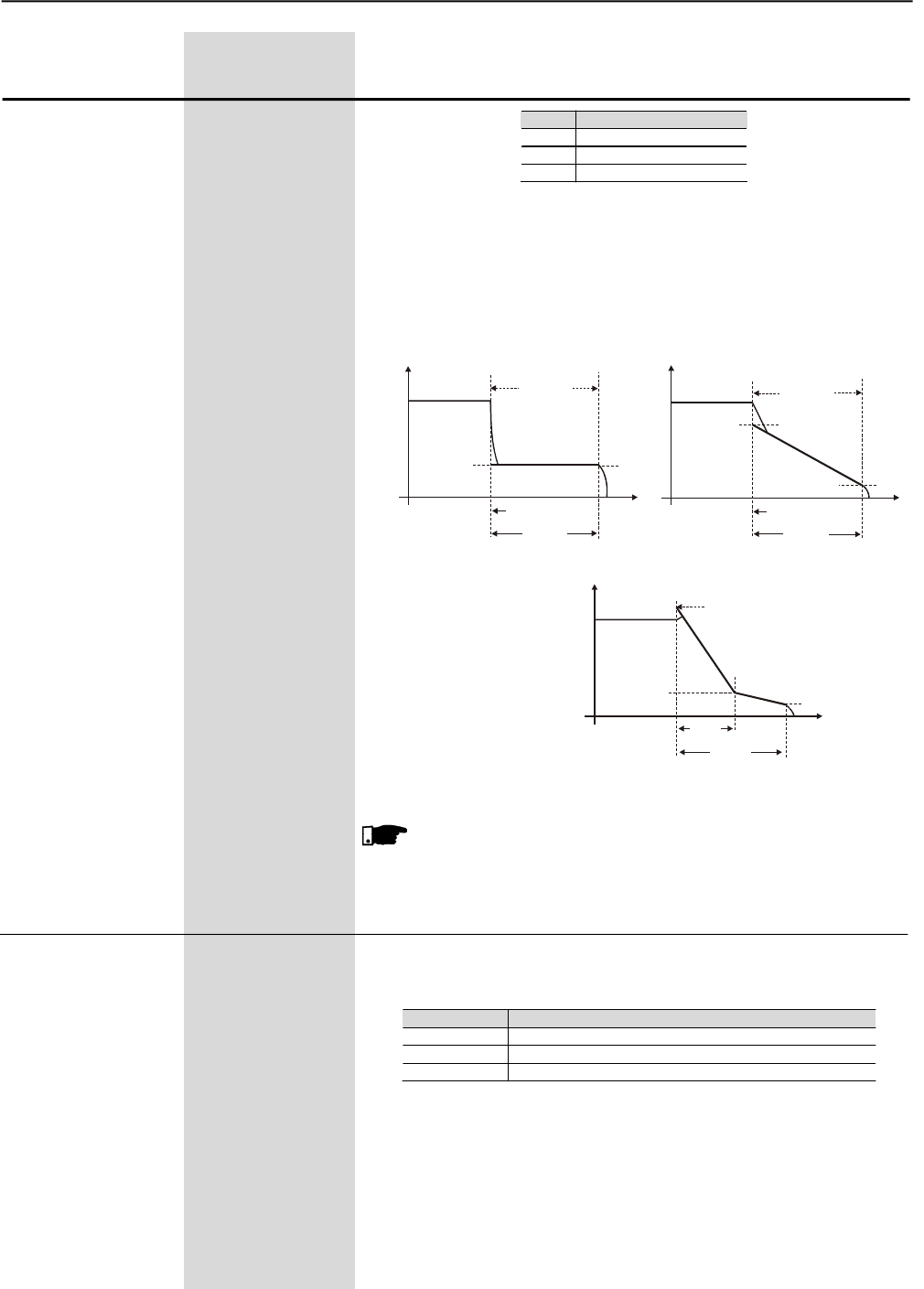
CHAPTER 6 - DETAILED PARAMETER DESCRIPTION
88
Range
[Factory Setting]
Parameter Unit Description / Notes
P125 (1) 1 to 3
Stopping Torque [ 1=constant]
Characteristics -
Here you can choose the torque limit profile that the
Soft-Starter SSW-06 shall supply to the motor during the start.
Three different types of torque profiles are available that permit
improving the speed performance during the start process.
P125 Stop torque profile
1 Constant (1 set point)
2 Linear (2 set points)
3 Quadratic (3 set points)
Figure 6.8 – Available torque profiles for the stop process
NOTE!
Choose the type of torque control, easier to program and set,
according to the knowledge about the characteristics of the load.
P126 10 to 100
End Torque [ 20 ]
for the Stop 1% Tn of the Motor
For more details about programming and application, refer to Torque
Control at P202.
P126 Action
1 (Constant)
P126 limits the maximum torque during the stop process
2 (Linear) P126 limits the end torque during the stop process
3 (Quadratic) P126 limits the end torque during the stop process
Here you can program the end torque limit or constant for the stop,
according to the torque type selected at P125.
Table 6.7 - Stop Torque Characteristics
Table 6.8 - Function of P126 according to P125
Tn(%)
P126
Stop
P125=1
P104
0
Tn Nominal
t(s)
P128
P126
Tn(%)
Tn Nominal
P127
P128
P104
t(s)
P126
P125=2
Stop
0
Tn(%)
P127
100%Tn
P125=3
P104
0
Tn Nominal
t(s)
P128
P126
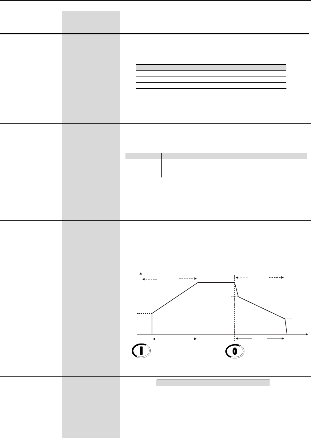
CHAPTER 6 - DETAILED PARAMETER DESCRIPTION
89
This parameter is reserved for future software versions with hydraulic
pump control type. The current version has been developed for the
control of centrifugal hydraulic pump, considering quadratic motor
loads.
For more details about the Pump Control, see P202.
P130 (1) 0
Pump Control [ 0=Pump ]
-
Range
[Factory Setting]
Parameter Unit Description / Notes
For more details about programming and application, refer to Torque
Control at P202.
P127 Action
1 (Constant) P127 not used
2 (Linear) P127 limits the torque when the motor is stopped
3 (Quadratic) P127 limits the intermediate torque for the stop
P128 1 to 99
Time for Minimum [ 50 ]
Stop Torque. 1% of P104
For more details about programming and application, refer to Torque
Control at P202.
P128 Action
1 (Constant) P128 not used
2 (Linear) P128 not used (time equal to 0)
3 (Quadratic) P128 time for the intermediate torque limit for the stop process.
Here you can program the time for the intermediate stop torque, as
percent of the maximum time programmed at P104, when the
quadratic torque has been selected at P125.
Table 6.9 – Function of P127 according to P125
Table 6.10 – Function of P128 according to P125
P127 10 to 100
Minimum Stop [ 50 ]
Torque 1% Tn of the Motor
Here you can program the initial torque limit or an intermediate torque
limit for the stop, when a linear torque or a quadratic torque has been
selected at P125.
Figure 6.9 – Start and Stop by Pump Control
U(V)
P101
0P102
Start 100%Un
P103
P104
P105
t(s)
Stop
Disable
Enable Pump Control
P140 (1) 0 or 1
External By-pass [ 0=Inactive ]
Contactor -
P140 Action
0 (Inactive) Without external By-pass contactor
1 (Active) With external By-pass contactor
Table 6.11 - External By-pass contactor
This function is enabled when the installation of an external By-pass
contactor is required that must be connected parallel to Soft-Starter
SSW-06.
CHAPTER 6 - DETAILED PARAMETER DESCRIPTION
90
SSW-06 offers two operation modes: Standard Connection or
connection inside the Motor Delta Connection.
Whena Standard Connection is used, the motor is connected in series
to the Soft-Starter SSW-06 through three cables.
When an Inside Delta Connection is used, the Soft-Starter SSW-06 is
connected separately in each winding through six cables. (See item
3.2.5.2). In this type of connection, the current that flows through of
the Soft-Starter SSW-06 is only the current of the inside delta motor
connection, in other words, 58% of the rated motor current. This
characteristic changes the relation between the Soft-Starter SSW-06
nominal currents and those of the motor. In this connection, the Soft-
Starter can be used with its rated current dimensioned in the following
way:
- 1.5 times the rated motor current during start;
- 1.73 times the rated motor current during full voltage.
During the start, the relation is lower due to the characteristics that
are common to this type of connection (inside delta) the Thyristors of
the Soft-Starter need to lead the same current in a lower time period,
increasing with this the losses in the Thyristor during the start.
The standard connection requires less output wiring. The Inside Delta
Motor Connection requires double wiring, but for short distances, this
will be a cheaper option for the Soft-Starter + motor + wiring set.
ATTENTION!
Do not operate the motor when P150 has not been programmed
correctly. Soft-Starter SSW-06 can be seriously damaged when
this parameter has not been programmed correctly.
P150 (1)(2) 0 or 1
Inside Delta [ 0=Inactive]
Motor Connection -
Range
[Factory Setting]
Parameter Unit Description / Notes
P150
0 (Inactive)
1 (Active)
Action
Soft-Starter SSW-06 with standard motor connection
Soft-Starter SSW-06 inside delta motor connection
Table 6.12 - Motor connection type
The models of models from 85A to 820A have an internal By-pass
contactor.
The models of models from 950A to 1400A do not have an internal
By-pass contactor.
When P140=1 in the models with an internal By-pass, the internal
By-pass will not enable.
The external By-pass contactor is used:
1) (Models without internal By-pass) for possibility one external
By-pass contactor;
2) (Models with internal By-pass) for instance when a direct start is
required in case of an emergency. The internal By-pass contactors
do not permit a direct start. These contactors can be enabled only
after the motor start has been realized by the thyristors;
3) (Models with internal By-pass) if the motor stalls frequently at
By-pass condition.
NOTE!
See the recommended setup at items 3.3 and 3.3.12 for more
Information.
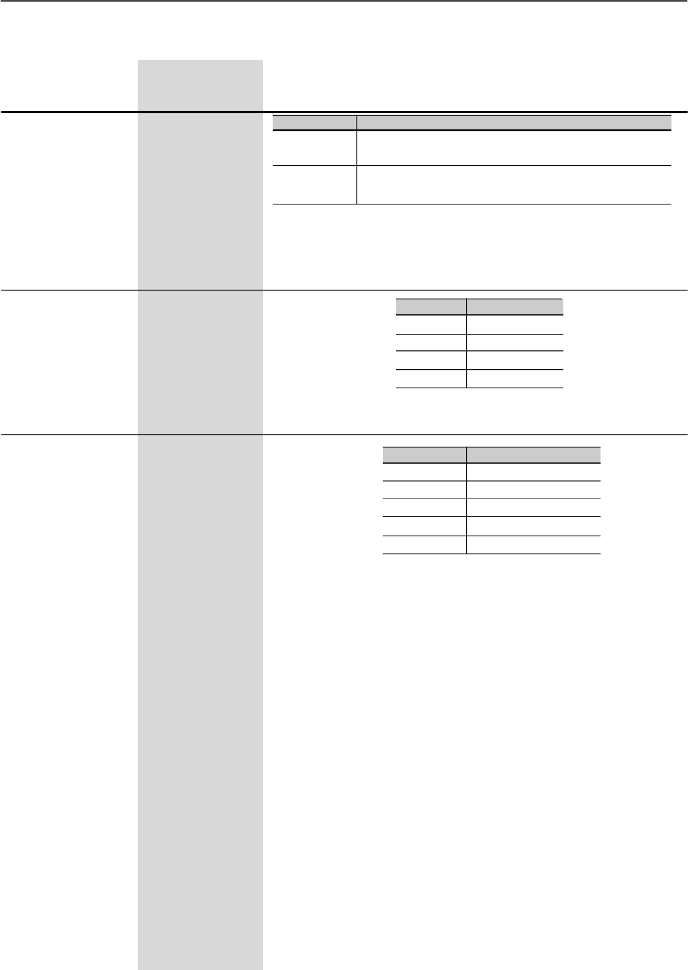
CHAPTER 6 - DETAILED PARAMETER DESCRIPTION
91
Range
[Factory Setting]
Parameter Unit Description / Notes
P202 (1) 0 to 4
Type of Control [ 0=Voltage
Ramp ]
-
P202
0
1
2
3
4
Type of Control
Voltage Ramp
Current Limit
Pump Control
Torque Control
Current Ramp
Table 6.15 - Types of control
Soft-Starter SSW-06 has five starting control types to better match all
application requirements.
Start by Voltage Ramp (1):
The start by Voltage Ramp is the most used starting method. Its
programming and setting is veryeasy. The Soft-Starter SSW-06 applies
the voltage to themotor without voltage or current feedback. This method
is used for loads with lower initial torque or quadratic torque.
This type of control can be used as initial operating test.
Start by Current Limit (2):
The maximum current level is maintained during the start and is set
according to the application requirements. Its programming and setting
is very easy.
This method is used for loads with higher initial torque or constant torque.
This type of control is used for matching the start process to the limits of
the power supply capacity.
Start by Current Ramp (3):
The maximum current level is limited during the start process, however
higher or lower current limits can be set during the start beginning.
6.3 CONFIGURATION PARAMETERS - P200 to P299
With the Factory Setting, the password will be P000=5.
To change the Password, see P000.
P200 0 or 1
Password [ 1 ]
-
P200
0 (inactive)
1 (Active)
Action
This Parameter allows parameter content changing,
independent of P000
Change of Parameter content is only possible, when P000 is
equal to the password value
P201 (2) 0 to 3
Language Selection [1=English]
-
Table 6.13 - Password
P201
0
1
2
3
Description
Portuguese
English
Espanish
German
Table 6.14 - Language selection

CHAPTER 6 - DETAILED PARAMETER DESCRIPTION
92
Range
[Factory Setting]
Parameter Unit Description / Notes
It can substitute the kick-start functions for loads with higher initial
torques.
This type of control is used for loads with lower or higher initial torques.
This type of control is used to match the start process to the limits of the
power supply capacity.
Start by Pump Control (4):
This type of control provides the required torque for starting and stopping
hydraulic centrifugal pumps smoothly.
It has a special algorithm for application in centrifugal pumps, where
loads with quadratic torques are present.
This special algorithm aims at to minimize pressure “overshoots” in the
hydraulic piping, which can result in breakdown or excessive pump
wearing.
Start by Torque Control:
The SSW-06 Soft-Starter has a high performance and totally flexible
torque control algorithm to meet the needs of anyapplication, for smoothly
starting or stopping the motor and its load.
Torque Control with 1 setting point (2):
This type of control allows a constant starting torque limitation.
Torque Control with 2 setting points (3):
This type of control allows the starting torque limitation through linear
ramp.
Torque Control with 3 setting points (4):
This type of control allows the setting of the starting torque limitation at
three different points: initial, intermediate and final. It also allows the
start of quadratic loads, among others.
(1) Very easy to set and program
(2) Easy to set and program
(3) Set and program, requires knowledge of the load to set and program
(4) Set and program, requires extensive knowledge of the load to set
and program
NOTES!
1) These types of controls are arranged according to the use and
programming difficulty level. Thus, we recommend starting with
the easier control modes first.
2) Every time the content of P202 is changed, the Soft-Starter will
start a sequence routine of minimum settings for each selected
type of control. You must run and set all parameters of this
sequence (up to the last) when required. Only after all settings
have been made can you start the motor.
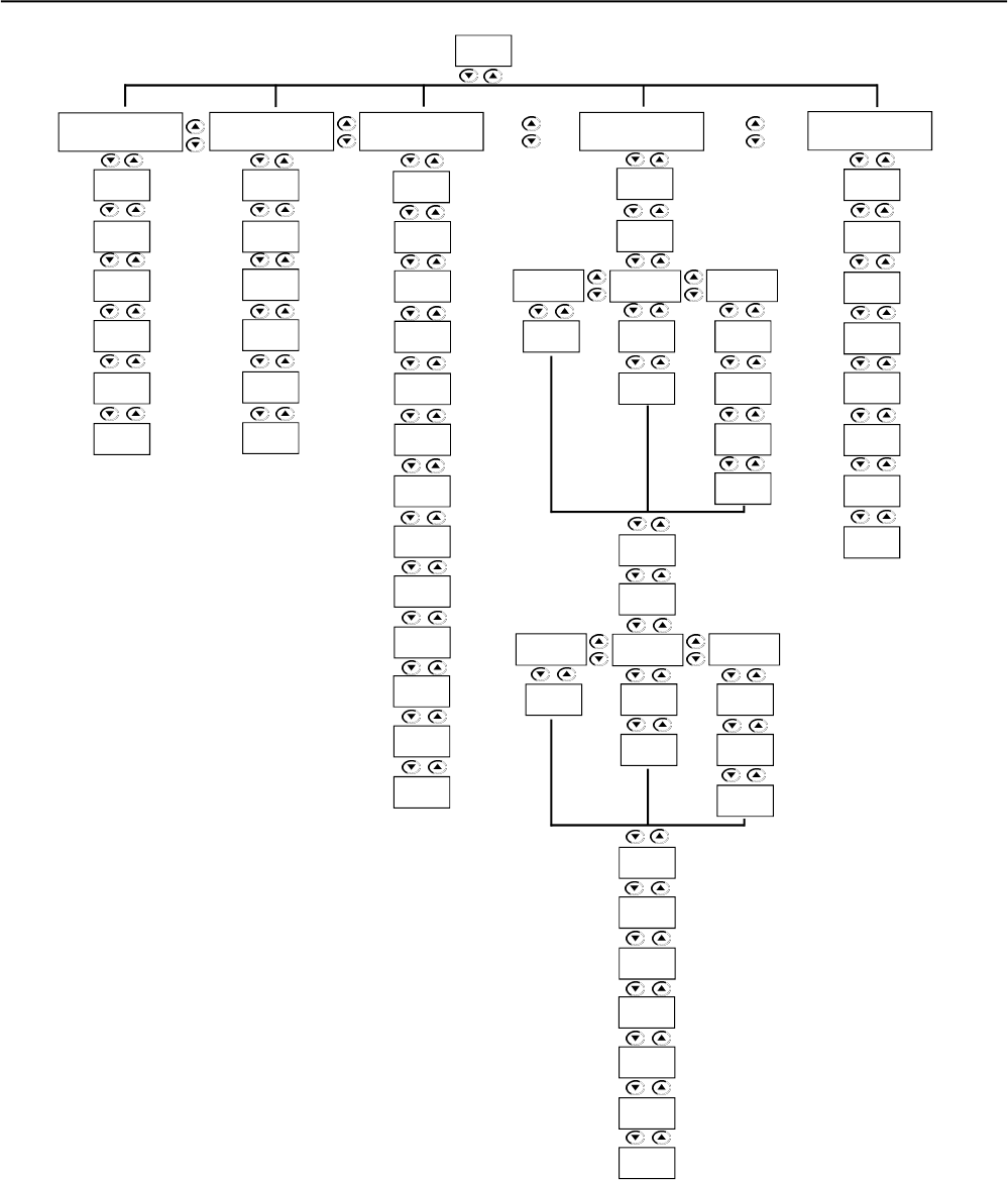
CHAPTER 6 - DETAILED PARAMETER DESCRIPTION
93
Figure 6.10 – Parameter sequence according to the selected type of control
P611
P610
P401
P400
P102
P101
Voltage
Ramp
Current
Limit
P202
Pump
Limit
P640
P406
P401
P400
P110
P102
P105
P104
P103
P102
P101
P130
P640
P406
P401
P400
P640
P406
P620
Torque
Control Current
Ramp
P120
P102
Constant Linear Square
P123
P122
P121
P122
P121
P121
P124
Constant Linear Square
P128
P127
P126
P127
P126P126
P402
P401
P400
P406
P405
P404
P640
P104
P125
P111
P110
P102
P112
P406
P401
P400
P640
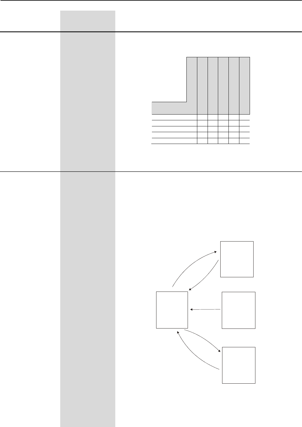
CHAPTER 6 - DETAILED PARAMETER DESCRIPTION
94
Range
[Factory Setting]
Parameter Unit Description / Notes
Parameters with note (2) indicated are not changed when Factory
Settings are loaded through P204 = 5.
To load User Parameter 1 (P204=7) and/or User 2 (P204=8) in the
operationarea of Soft-Starter SSW-06, it is necessaryfor User Memory
1 and/or User Memory2 to bebeen saved previously (P204=10 and/or
P204=11).
P204 (1) 0 to 11
Load/Save [ 0 ]
Parameter -
Figure 6.11 - Parameter Transfer
The table below shows the relation between the adopted starting control
type and the automatically selected stop control type.
Table 6.16 – Stop/Start Operation
User
Memory 1
Factory
Setting
(WEG
Standard)
P204=5
Current
Parameter of
Soft-Starter
SSW-06
User
Memory 2
P204=11
P204=10
P204=7
P204=8
START
STOP
Voltage Ramp
Current Limit
Current Ramp
Pump Control
Torque Control
Voltage Ramp X
Current Limit X
Current Ramp X
Pump Control X
Torque Control X
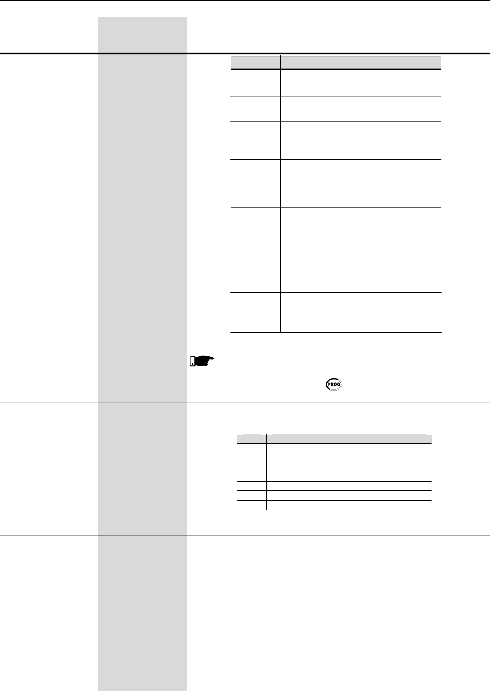
CHAPTER 6 - DETAILED PARAMETER DESCRIPTION
95
Range
[Factory Setting]
Parameter Unit Description / Notes
P204 Action
0, 1, 2, Not used:
4, 6, 9 No action
3Reset P043:
Resets Running Time
5Loads Factory Default:
Loads current Soft-Starter parameter
with factory setting
7Loads User 1:
Loads current Soft-Starter parameter
with the values stored in
Memory 1.
8Loads User 2:
Loads current Soft-Starter parameter
with the values stored in
Memory 2.
10 Save User 1:
Transfer the current parameter
contents of the Soft-Starter to memory 1
11 Save User 2:
Transfer the current parameter
contents of the Soft-Starter to memory 2
NOTE!
Parameter loading/saving will be executed only after parameter
setting and after the key has been pressed .
This Parameter selects which parameter listed below will be displayed
after the Soft-Starter has been powered-up:
P205 0 to 7
Display Default [ 2 ]
Selection -
In the event of a fault trip, except for E10, E15, E24, E28, E29,
E30, E31, E41, E62, E63, E67, E70, E71, E72, E75, E76 and E77,
the Soft-Starter SSW-06 can initiate an automatic reset after the
time given by P206 is elapsed.
If P206 2 Auto-Reset does not occur.
If afterAuto-Reset the same fault is repeated three times consecutively,
the Auto-Reset function will be disabled. A fault is considered
consecutive if it happens again within 30 seconds after Auto-Reset.
Thus if an error occurs four times consecutively, it will be displayed
permanently (and the Soft-Starter will be disabled).
P206 0 to 600
Auto-Reset Time [ 0=Inactive ]
1s
Table 6.17 - Action of loading/saving parameters
P205 Status
1 P001 (Motor current % In of the Soft-Starter)
2 P002 (Motor current % In of the Motor)
3 P003 (Motor current (A))
4 P004 (Supply Line Voltage)
5 P005 (Supply Line Frequency)
6 P006 (Soft-Starter Status)
7 P007 (Output Voltage)
Table 6.18 - Options displays default
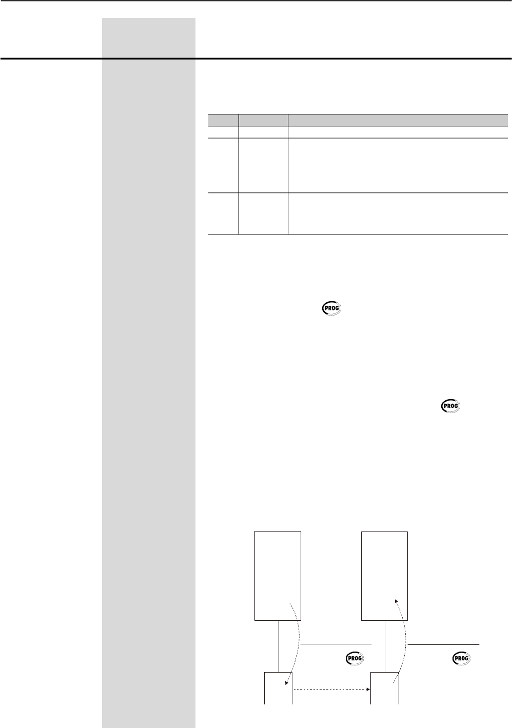
CHAPTER 6 - DETAILED PARAMETER DESCRIPTION
96
Range
[Factory Setting]
Parameter Unit Description / Notes
The copy function is used to transfer the content of the parameters
from one Soft-Starter SSW-06 to another. The Soft-Starters must be
of the same type (voltage/current) and the same software version must
be installed.
P215 (1) 0 to 2
Copy Function (HMI) [ 0=Off ]
-
P215 Action Explanation
0 Off -
1 Copy Transfers the current parameter contents from the
SSW HMI Soft-Starter and from Users 1/2 to the non volatile (HMI)
keypad memory (EEPROM). The current Soft-Starter
parameters are not changed.
2 Paste Transfers the contents of the non-volatile (HMI) keypad
HMI SSW memory (EEPROM) to the current Soft-Starter SSW-06
parameters and to user 1 or 2 memories.
Procedures:
1. Connect the Keypad to the Soft-Starter SSW-06 from which the
parameters will be copied (Soft-StarterA);
2. Set P215=1 (copy) for transferring the parameterfrom the Soft-StarterA
to the HMI. Press the key . While copyfunction is being executed,
the display will show COPY. P215 resets automatically to 0 (Inactive)
after the transfer has been completed.
3. Disconnect the keypad (HMI)from the Soft-Starter SSW-06.
4. Connect the same Keypad to the Soft-Starter SSW-06 to which the
parameters should be transferred (Soft-Starter B).
5. Set P215=2 (paste) for transferring the content from the non-volatile
keypad memory (EEPROM containing the parameter of the
Soft-Starter A) to the Soft-Starter B. Press the key . While the
keypad is executing the copy function, the display shows COPY.
When P215 returns to 0, the parameter transfer has been concluded.
Now Soft-StartersAand B have the same parameter content.
Please remember:
If Soft-Starters A and B command different motors, please check the
motor parameters of Soft-Starter B.
For copying the parameter contents from Soft-StarterA to other
Soft-Starter, repeat procedures 4 and 5 above.
Table 6.19 - Copy function
Figure 6.12 - Parameter Copying from “Soft-Starter A” to “Soft-Starter B”
Soft-Starter
A
Parameters
Soft-Starter
B
Parameters
EEPROM EEPROM
HMI HMI
SSW HMI (copy)
P215=1
Press. P215=2
Press.
HMI SSW(paste)
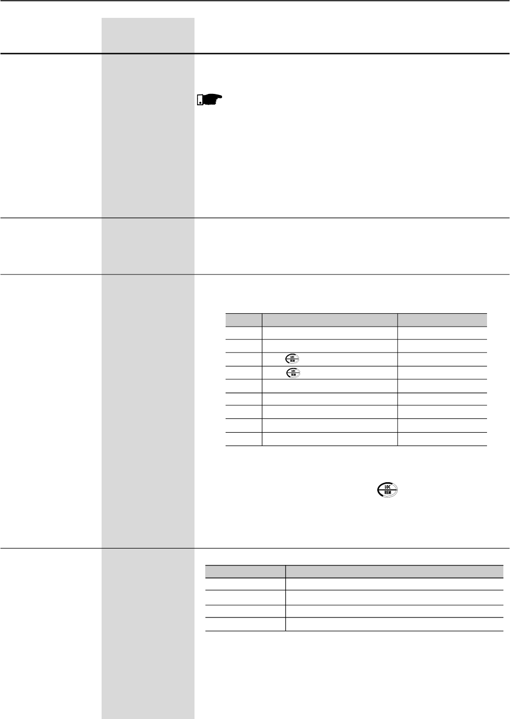
CHAPTER 6 - DETAILED PARAMETER DESCRIPTION
97
Range
[Factory Setting]
Parameter Unit Description / Notes
The Keypad (HMI) can not be operated while it is executing the read
or write procedures.
NOTES!
1) If the Keypad (HMI) has saved parameters of a “different version”
than that installed in Soft-Starter SSW-06 to which it is trying
to copy the parameters, the operation will not be executed and
Soft-Starter SSW-06 will display error E10 (Error: Copy Function
not permitted). “Different Version” are those that are different in
“x” or “y”, supposing that the numbering of Software Versions is
described as Vx.yz.
2) This function changes allSSW-06 parameters to the newvalues.
It allows the adjustment of the LCD Display contrast, as a function of
the viewing angle. Increase/decrease the parameter content untill the
best contrast is obtained.
P218 0 to 150
LCD Display [ 127 ]
ContrastAdjustment -
Defines the command source that will select between the LOCAL /
REMOTE selection condition.
P220 (1) 0 to 8
LOCAL/REMOTE [ 2 ]
Source Selection -
P220 Local/Remote Selection Default Condition
0 Always Local Condition -
1 Always Remote Condition -
2 Key of the Keypad (HMI) Local
3 Key of the Keypad (HMI) Remote
4 Digital Inputs DI4 ... DI6 (P266 ... P268)
5 Serial Communication Local
6 Serial Communication Remote
7 Fieldbus Communication Local
8 Fieldbus Communication Remote
Default condition = when Soft-Starter SSW-06 is powered-up (start-up)
In the factory default setting, the key of the Keypad (HMI) will
select Local or Remote Mode. When powered up, the Soft-Starter
SSW-06 starts in Local mode.
Defines the origin of the Soft-Starter SSW-06 enable/disable commands.
P229 (1) 0 to 3
Command Selection [ 0=HMI ]
-Local Condition -
P230 (1) 0 to 3
Command Selection [ 0=Terminals ]
-Remote Condition -
P229/P230
0
1
2
3
Origin of the Commands
Keypad keys (HMI)
Digital Input DIx
Serial Communication
Fieldbus Communication (DevideNet or Profibus DP)
Table 6.20 - LOCAL/REMOTE Selection
Table 6.21 - Command Selection
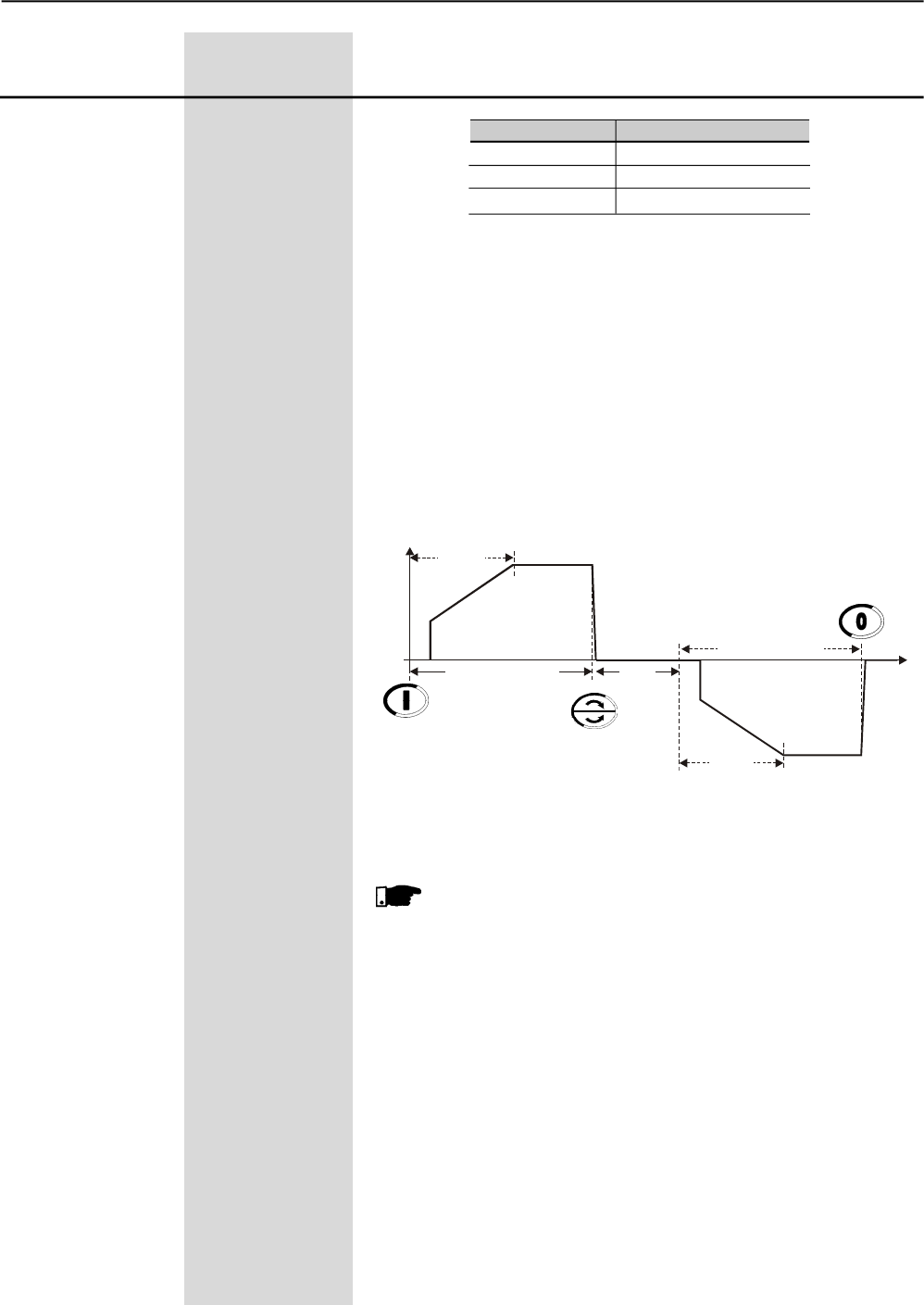
CHAPTER 6 - DETAILED PARAMETER DESCRIPTION
98
Range
[Factory Setting]
Parameter Unit Description / Notes
Table 6.22 - FWD/REV selection
P231
0
1
2
Action
Inactive
By Contactor
JOG Only
“By Contactor”
This option enables the possibilityof changing thedirection of rotation
via contactors connected at the input power supply.
The new method implemented in the Soft-Starter SSW-06 allows the
use of only two contactors to change the motor direction of rotation
and isolate the power supply at the same time.
Possibility of changing the direction of rotation with inside delta mo-
tor connection.
When the motor is stopped the contactors are opened. When the
motor is enabled the specific contactor is enabled.
Figura 6.13 – Troca do sentido de giro via contator
NOTES!
1. Set P277=1 (FWQ/REV-K1) and P278=1 (FWQ/REV-K2)
before connecting the power supply.
2. The method used to start the motor to a new direction of
rotation will be the same as the one set to start the motor
at the first time.
3. The motor will start again only after the time set at P630
(time delay after starting).
4. See the recommended setup at items 3.3 and 3.3.8.
Enable
U(V) 100%Un
t(s)
0
100%Un
Start
Disable
P630
FWD/REV - K1 Closed
FWD/REV - K2 Closed
Start
P231 (1)
FWD/REV Selection 0 to 2
[ 0=Inactive ]
-
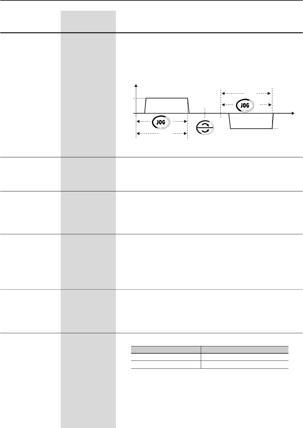
CHAPTER 6 - DETAILED PARAMETER DESCRIPTION
99
Range
[Factory Setting]
Parameter Unit Description / Notes
Sets the gain of the analog output AO1.
For P252=1.000 the value of output AO1 is set according to the
description in Figure 6.15.
P252 0.000 to 9.999
AO1Analog Output [ 1.000 ]
gain -
Check the possible options in Table 6.24 and Figure 6.15.
For the values shown in Table 6.24, P253=2, P254=1000 and
AO2=20mA.
P253 0 to 10
AO2Analog Ouput [ 0=Not Used ]
Function -
(0 to 20)mA or
(4 to 20)mA
Sets the gain of the analog output AO2.
For P254=1.000 the value of output AO2 é is set according to the
description in Figure 6.15.
P254 0.000 to 9.999
AO2Analog Output [ 1.000 ]
Gain 0.001
It selects the signal type of the current analog output AO2.
P255 0 or 1
AO2Analog Output [ 0=0-20mA ]
Type (0 to 20)mA or -
(4 to 20)mA
P255 Output type
0 (0 to 20)mA
1 (4 to 20)mA
For transforming the current analog outputAO2 to a voltage output of
0 to 10V, connect a resistor of 500± 1% 0.5W in parallel with the
output signal a resistor of 500± 1% 0.5W.
Remember when the output type is selected to 4 to 20mA, this will be
the total range of the signal output.
0% of the signal = 4mA and 100% of the signal = 20mA.
Table 6.23 - AO2 signal type
Check possible options in table 6.24 and Figure 6.15.
For the values shown in Table 6.24, P252=1000 andAO1=10V.
P251 0 to 10
AO1 Output Function [ 0=Not used ]
(0 to 10)V -
Figure 6.14 - Motor direction of rotation with “Jog only”
U(V)
0
P511
P102
P102
P511
t(s)
“JOG Only”
This option allows the slow speed with Jog in both forward and reverse
directions without auxiliary contactors connected at the input power
supply.
See more information andthe notes at the P510 and P511 parameters.
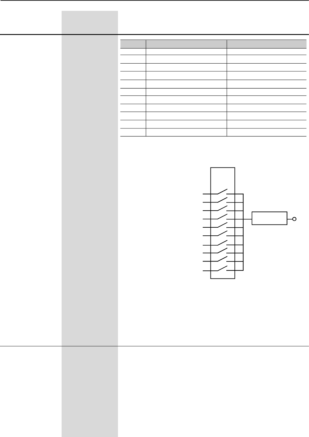
CHAPTER 6 - DETAILED PARAMETER DESCRIPTION
100
Range
[Factory Setting]
Parameter Unit Description / Notes
Scale of the Analog Output indications:
- Full scale =10V: for Output AO1.
- Full scale =20mA for Output AO2.
Check the available options in Table 6.25.
The states of the digital inputs can be monitored in parameter P012.
“Enable/Disable” = Closed/Open Digital Input DI1 respectively. No
specific Parameter need to be programmed for this function. Only
programming of the Enable/Disable command for the digital input is
required. .
“Start/Stop” = When P264=1 (Start/Stop at three wires) is
programmed, the digital input DI1 and DI2 become automatically:
DI1=Start and DI2=Stop. Use pulsing switches.
P264(1) 0 to 2
Digital Input DI2 [ 2=Error Reset ]
Function -
P265(1) 0 to 2
Digital Input DI3 [ 0=Not used ]
Function -
P266(1) 0 to 6
Digital Input DI4 [ 0=Not used ]
Function -
Current (%In of the SSW)
Input Voltage (%Un of the SSW)
Output Voltage (%Un of the SSW)
Power Factor
Motor Thermal Protection
Power (W)
Power (VA)
Torque (% In Motor)
Fieldbus
Serial
P251
P253
Gain
P252, P254
AO1
AO2
Figure 6.15 - Block diagram of the Analog Outputs
Table 6.24 - Functions of the Analog Outputs
P251/P253 Function of the Analog Output Full Scale when
0 Not used -
1 Current in % In of the SSW 5 x P295
2 Input Voltage in %Un of the SSW 1.5 x P296(max.)
3 Motor Voltage in % Un of the SSW 1.5 x P296(max.)
4 Power Factor P008 = 1.00
5 Thermal Protection P050 = 250%
6 Power in W 1.5 x 3 x P295 x P296(max.) x P008
7 Power in VA 1.5 x 3 x P295 x P296(max.)
8 Torque in %Tn of the Motor P009 = 100%
9 Fieldbus 16383 (3FFFh)
10 Serial 16383 (3FFFh)
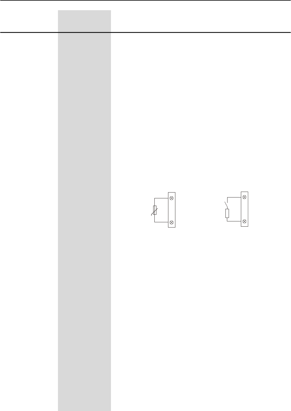
CHAPTER 6 - DETAILED PARAMETER DESCRIPTION
101
Range
[Factory Setting]
Parameter Unit Description / Notes
P267(1) 0 to 6
Digital Input DI5 [ 0=Not used ]
Function -
P268(1) 0 to 7
Digital Input DI6 [ 0=Not used ]
Function -
“Local/Remote” = Digital Input is open/closed respectively. Do not
program more than one digital input for this function.
“Error Reset” = Resets the errors when the digital input is closed.
Use only pulsing switch. When the input remains closed, the error
reset will not act.
“No External Error” = No External Error will be present when the
digital input is closed.
“General Enabling/General Disabling” = Closed/Open to the digi-
tal input, respectively. This function allows the motor to start when it
is in general enabling and to stop without a deceleration ramp when
given the general disabling command. There is no need to program
General Enabling to start the motor via digital input.
If the general enabling is programmed via digital input, this must be
closed to allow the motor to start, even if the commands are not via
digital inputs.
“Motor Thermistor” = The DI6 digital input is associated to the
input of the motor thermistor (PTC). If you want to used the DI6 as a
normal digital input, you must program the Parameter P268 to the
desired function and you must connect in series to the input a resistor
with its resistance between 270W and 1600W, as shown below:
“Rotation Direction” = Digital input open K1 “on” and K2 “off”, digital
input closed K1 = “off” and K2 “on” (item 3.3.8). This enables the
change control of the rotation direction through digital input. Do not
program more than one digital input for this function
“Jog” = It is possible to enable the slow speed with Jog via Digital
Input when it is closed. Use a push-botton only. If more than one
digital input was programmed for this function, anyone which is closed
enables the Jog.
“Brake Off” = It is possible to disable the braking methods when the
digital input is open, for extra safety, for monitory the real motor
standstill and disable the braking immediately. If more than one digital
input is programmed for this function, anyone which is opened disables
the braking immediately.
Figure 6.16 - PTC connection diagram or Digital Input
Contact
12
13
X1:
DI6 (P268)
R=(270 to 1600)
DI6 (P268=7)
12
13
X1:
+ tº
PTC
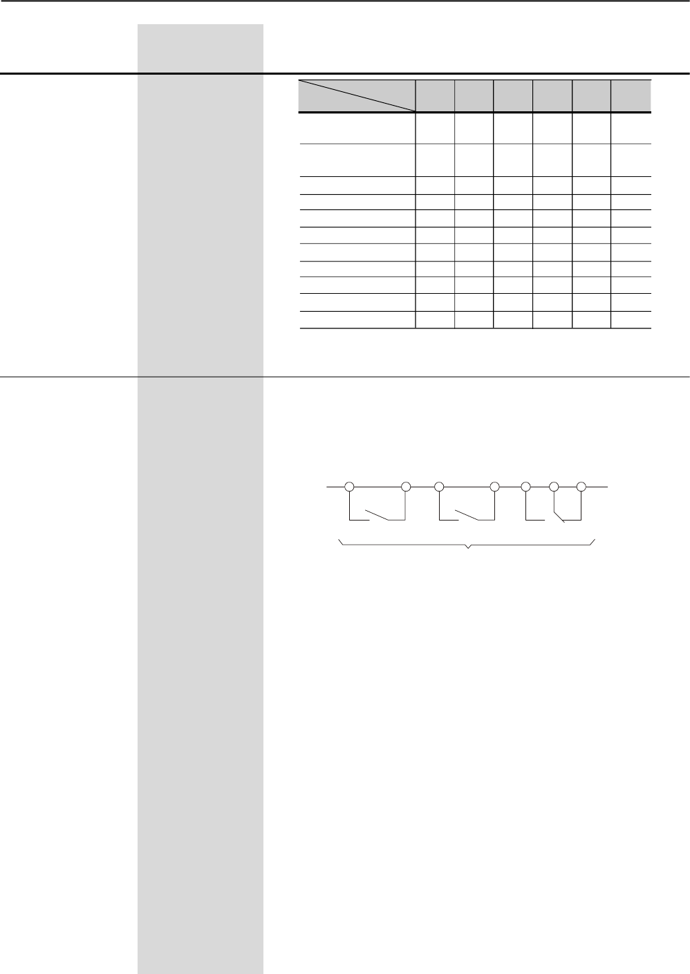
CHAPTER 6 - DETAILED PARAMETER DESCRIPTION
102
P277(1) 0 to 9
RL1 Relay Output [ 1=in
Function Operation ]
-
P278(1) 0 to 9
RL2 Relay Output [ 2=at Full
Function Voltage ]
-
P279(1) 0 to 9
RL3 Relay Output [ 6=No
Function Fault ]
-
Check the available options in Table 6.26.
The status of the digital outputs can be monitored in the Parameter
P013.
The digital output will be enabled when the function which has been
programmed for the digital output is true.
Figure 6.17 - Status of the relay digital outputs when disabled.
“Not used” = the digital outputs are disabled.
“In Operation” =the output willbe enabledinstantly with the Soft-Starter
SSW-06 Enable command, and will onlybe disabled when the
Soft-Starter SSW-06 receives the command Disable, or when the end
of the deceleration ramp is reached, if programmed.
“Full Voltage” = the output will be enabled when the Soft-Starter
SSW-06 reaches 100% Un and it will be disabled when the Soft-Starter
SSW-06 receives the command Disable.
“External By-pass” = its operation is similar to the “Full Voltage”
operation, but it must be applied only when the use of an external
By-pass contactor is required. See P140 and the recommended setup
at items 3.3 and 3.3.12.
“FWD/REV-K1” = This operation is similar to the “In Operation”, but it
must be enabled with forward motor direction of rotation. See P231
and the recommended setup at items 3.3 and 3.3.8.
“FWD/REV-K2” = This operation is similar to the “In Operation”, but it
must be enabled with reverse motor direction of rotation. See P231
and the recommended setup at items 3.3 and 3.3.8.
“DC-Braking” = The output will be enabled during the DC-Braking is
active. See P500 and the recommended setup at items 3.3 and 3.3.11.
The output will be enabled when DC-Braking is active. See P500 and
the recommended set-up at items 3.3 and 3.3.11.
Range
[Factory Setting]
Parameter Unit Description / Notess
DIx Parameter DI1 P264 P265 P266 P267 P268
Function (DI2) (DI3) (DI4) (DI5) (DI6)
Not used - 0 0 0 0 0
Enable/Disable -----
or Start
Stop (Three wires) - 1 - - - -
General Enable - - 1 - - -
FWD/VERREV - - - 1 1 1
Local/Remote - - - 2 2 2
No external Error - - - 3 3 3
JOG - - - 4 4 4
Brake Off - - - 5 5 5
Error Reset - 2 2 6 6 6
Motor Thermistor - - - - - 7
Table 6.25 - Functions of the Digital Inputs
18 19 20 21 22 23 24
RL3
RL2
RL1
X1C
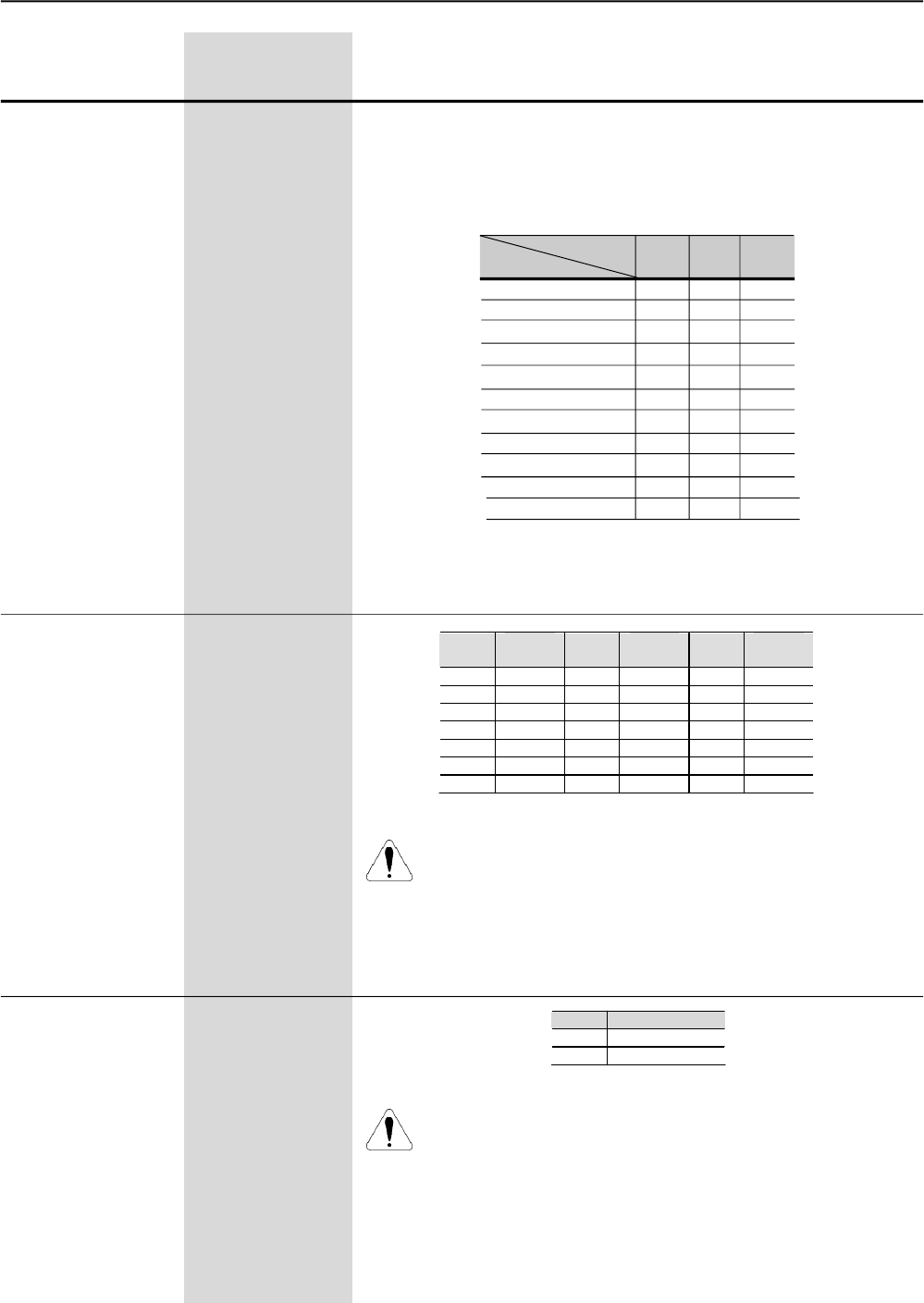
CHAPTER 6 - DETAILED PARAMETER DESCRIPTION
103
Range
[Factory Setting]
Parameter Unit Description / Notes
P295 (1) (2) 0 to 20
Rated Current [ According to the
rated current of the
Soft-Starter
SSW-06 ]
-
ATTENTION!
Program always this parameter with a voltage that matches
exactly the voltage of the model of your Soft-Starter SSW-06.
P296 (1) (2) 0 or 1
Rated Voltage [ According to the
rated voltage of the
Soft-Starter
SSW-06 ]
-
Table 6.26 - Functions of the Relay Outputs
P296 Voltage Range
0 220/575V
1 575/890V
Table 6.28 - Voltage range
RLx Parameter P277 P278 P279
Function (RL1) (RL2) (RL3)
Not used 0 0 0
In Operation 1 1 1
At full Voltage 2 2 2
External By-pass 3 3 3
FWD/REV-K1 4 - -
FWD/REV-K2 - 4 -
DC-Braking 5 5 5
No Fault 6 6 6
Fault 7 7 7
Fieldbus 8 8 8
Serial 9 9 9
“No Fault” = the output is enabled without error. i. and., if the Soft-
Starter SSW-06 is not disabled due to any error.
“Fault” = the output is enabled with error. i. and., if the Soft-Starter
SSW-06 is disabled due to any error.
ATTENTION!
Always Program thisparameter with a current that matches exactly
the current of the model of your Soft-Starter SSW-06. Error in
programmingthisparametermaydamageyourSoft-StarterSSW-06
exactly.
Table 6.27 – Rated current configuration
P295 Rated
Current P295 Rated
Current P295 Rated
Current
0 10A 7 130A 14 480A
1 16A 8 170A 15 604A
2 23A 9 205A 16 670A
3 30A 10 255A 17 820A
4 45A 11 312A 18 950A
5 60A 12 365A 19 1100A
6 85A 13 412A 20 1400A
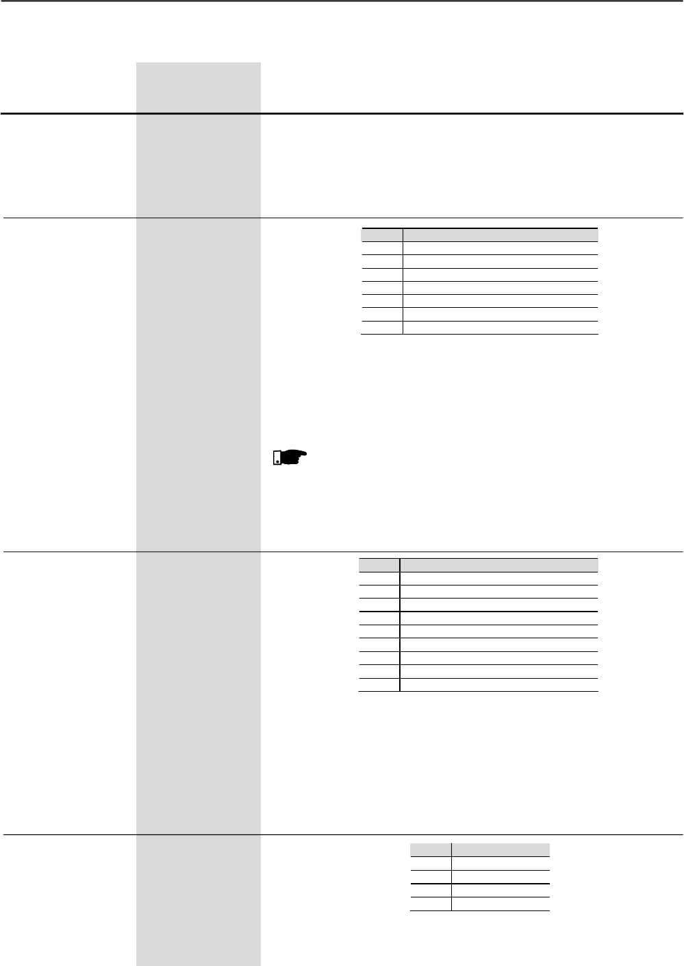
CHAPTER 6 - DETAILED PARAMETER DESCRIPTION
104
Defines the Soft-Starter SSW-06 address on the serial Modbus-RTU
communication network.
For more information, refer to the Serial Communication Manual for
the Soft-Starter SSW-06.
P308 (1)(2) 1 to 247
Soft-Starter address [ 1 ]
on the Serial 1
Communication
Network
6.4 - SERIAL COMMUNICATION PARAMETERS – P300 to P399
P309 Action
0 Inactive
1 Profibus-DP (1 Input and 1 Output)
2 Profibus-DP (4 Inputs and 4 Outputs)
3 Profibus-DP (7 Inputs and 7 Outputs)
4 DeviceNet (1 Input and 1 Output)
5 DeviceNet (4 Inputs and 4 Outputs)
6 DeviceNet (7 Inputs and 7 Outputs)
P309 (1)(2) 0 to 6
Fieldbus [ 0=Inactive ]
Communication -
Board Enabling
Table 6.29 - Fieldbus Communication Protocol Type
Range
[Factory Setting]
Parameter Unit Description / Notes
Enables and defines the protocol type of the Fieldbus Communication
Board.
For more information, refer to theFieldbus Communication Manual for
the Soft-Starter SSW-06.
NOTE!
Without a Fieldbus Communication Board, this parameter must
remain at 0 (not used).
Defines the protocol standards of the serial Modbus-RTU
communication protocol.
For more information, refer to Serial Communication Manual for the
Soft-Starter SSW-06.
P312 (1)(2) 1 to 9
Protocol Type and [ 1=Modbus-RTU
Transfer Rate of (9600bps, no
the Serial parity) ]
Communication. -
P312 Action
1 Modbus-RTU (9600bps, no parity)
2 Modbus-RTU (9600bps, odd parity)
3 Modbus-RTU (9600bps, even parity)
4 Modbus-RTU (19200bps, no parity)
5 Modbus-RTU (19200bps, odd parity)
6 Modbus-RTU (19200bps, even parity)
7 Modbus-RTU (38400bps, no parity)
8 Modbus-RTU (38400bps, odd parity)
9 Modbus-RTU (38400bps, even parity)
Table 6.30 - Serial Communication Protocol Type
P313 0 to 3
Serial and Fieldbus [ 0=Off ]
Communication Error -
Actions
(E28, E29 and E30)
P313 Action
0 Off
1 Disable
2 General Disable
3 Changes to Local
Table 6.31 - Error action of the Serials and Fieldbus Communication
CHAPTER 6 - DETAILED PARAMETER DESCRIPTION
105
Range
[Factory Setting]
Parameter Unit Description / Notes
Defines the action to be adopted when some errors relating to the
Serial or Fieldbus Communication occur.
For more information refer to the Serial Communication Manual and/
or to the Fieldbus Communication Manual for the Soft-Starter SSW-06.
NOTE!
When Serial Communication or Fieldbus Communication is not
used, this parameter must remain at 0 (not used).
Allows time programming for the fault detection during the serial
Modbus-RTU communication. So you can adopt an action when, for
instance, the communication with the master of the Modbus-RTU
network is lost.
For more information, refer to the Soft-Starter SSW-06 Fieldbus
Communication Manual.
NOTE!
This parameter must remain at 0 (not used), when the serial
communication is not being used.
P314 (1) 0 to 999
Timeout Time for [ 0=not used ]
Serial Communication 1s
Telegram Reception
This parameter allows selecting the number of the first parameter to
be selected, which content will be sent from the Soft-Starter SSW-06
to the Master of the Fieldbus network.
For more details, refer to the Soft-Starter SSW-06 Fieldbus
Communication Manual.
P315 (1) 0 to 999
Read Parameter [ 0 ]
via Fieldbus 1 1
This parameter allows selecting the number of the second parameter
to be selected, which content will be sent from the Soft-Starter SSW-06
to the Master of the Fieldbus network.
For more details, refer to the Soft-Starter SSW-06 Fieldbus
Communication Manual.
P316 (1) 0 to 999
Read Parameter [ 0 ]
via Fieldbus 2 1
This parameter allows selecting the number of the third parameter to
be selected, which content will be sent from the Soft-Starter SSW-06
to the Master of the Fieldbus network.
Formoredetails,refertotheSoft-StarterSSW-06FieldbusCommunication
Manual.
P317 (1) 0 to 999
Read Parameter [ 0 ]
via Fieldbus 3 1

CHAPTER 6 - DETAILED PARAMETER DESCRIPTION
106
Range
[Factory Setting]
Parameter Unit Description / Notes
6.5 MOTOR PARAMETERS - P400 to P499
Set this parameter value according to the motor nameplate and the
connection diagram in the terminal box.
The motor protection is based on the content of this parameter.
P400 (1) 0 to 999
Motor Rated Voltage [ 380 ]
1V
Set this parameter value according to the motor nameplate.
The motor protection against current and the current limit are based
on this parameter content.
NOTES!
1) To ensure that these protections operate correctly, the motor
rated current must not be lower than 30% of the rated current
of the Soft-Starter SSW-06.
2) The use of motors that operate with load duties lower than
50% their rated loads are not recommended.
3) Program the rated current of the motor according to the power
supply voltage.
P401 (1) 0.0 to 1500
Motor Rated Current [ 20.0 ]
0.1A
Set the motor speed according to the motor nameplate data.
The motor speed must be the same as indicated on the motor
nameplate, already considering its slip.
P402 (1)
Motor Rated
Speed
400 to 3600
[ 1780 ]
1 rpm
Set the motor power according to the motor nameplate data.
If the power is in CV or HP, multiply the value by 0,74kW.
P404 (1)
Motor Rated
Power
0.1 to 2650
[ 75 ]
0.1kW
Set the Motor Power Factor according to the motor nameplate data.
P405 (1)
Motor Power
Factor
0 to 1.00
[ 0.89 ]
0.01
Set the Service Factor according to the motor nameplate.
The current protections are based on the content of this parameter.
P406 (1) 0 to 1.50
Service Factor [ 1.00 ]
0.01
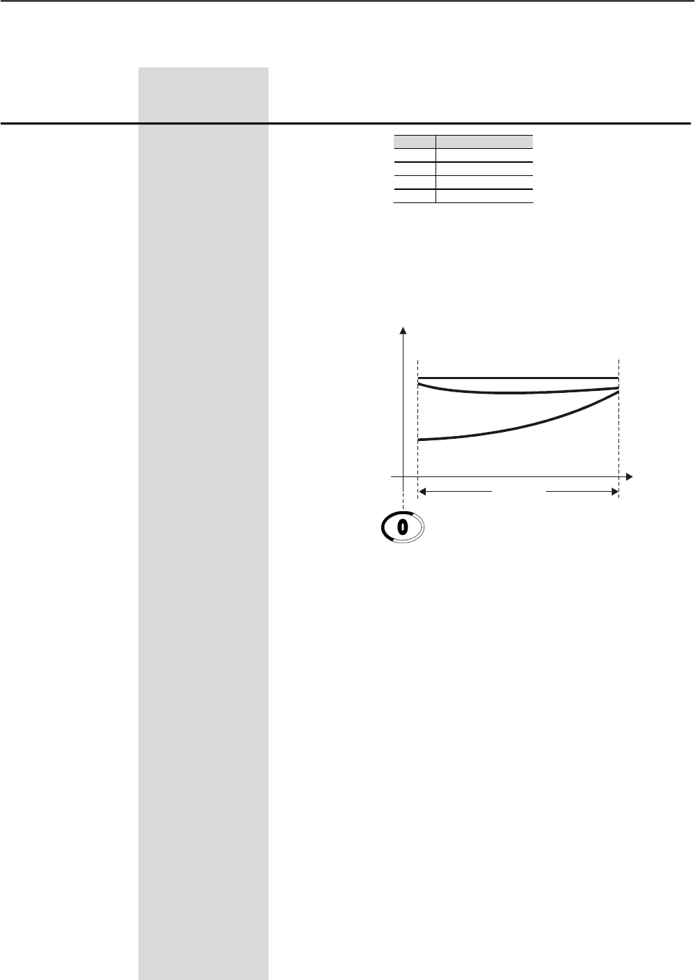
CHAPTER 6 - DETAILED PARAMETER DESCRIPTION
107
Range
[Factory Setting]
Parameter Unit Description / Notes
6.6 SPECIAL FUNCTION PARAMETERS - P500 to P599
P500 Action
0 Inactive
1 Reverse Braking
2 Optimal Braking
3 DC-Braking
Table 6.32 - Braking Methods selection
There are three braking methods implemented in the Soft-Starter
SSW-06. These braking methods should be used only when fast
stop is necessary. stops are necessary.
Figure 6.18 - Braking Torque
“Reverse Braking”
This is an efficient method to stop very high inertia loads.
The motor will stop viaAC level voltage in reverse direction until near
20% of the nominal speed when a Optimal Braking is applied to stop
the motor.
The motor will stop viaAC level voltage in reverse direction until close
to 20% of the rated speed, when Optimal Braking is applied to stop
the motor.
The Reverse BrakingAC level and Optimal Braking are set in P502.
Two contactors are needed.
It is compatible with the Soft-Starter SSW-06 inside delta motor
connection, except for two and eight pole motors.
P501
Stopped
Disable
Nominal
Speed
Braking
Torque
DC-Braking
Reverse Braking
Optimal Braking
P500 (1)
Braking Methods 0 to 3
[ 0=Inactive ]
-
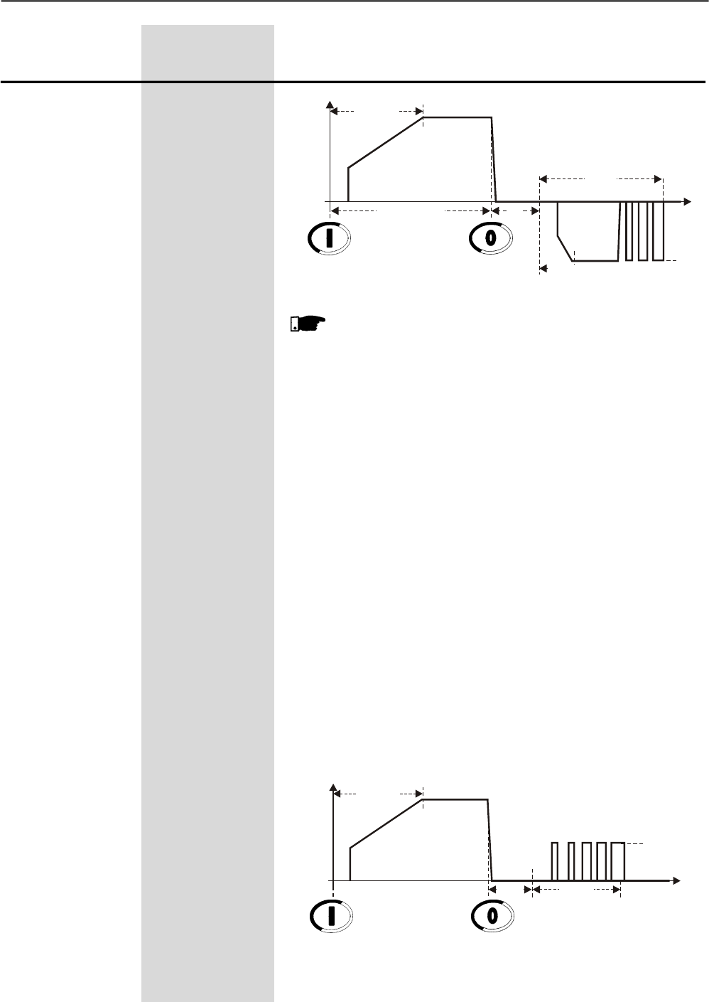
CHAPTER 6 - DETAILED PARAMETER DESCRIPTION
108
Range
[Factory Setting]
Parameter Unit Description / Notes
Figura 6.19 - Reverse Braking
Start
U(V) 100%Un
Enable Disable
Start P502
t(s)
P501
FWD/REV-K2 Closed
FWD/REV-K1 Closed 1s
0
NOTES!
1. The contactors must be the same model and withstand the
motor starting current. For security use auxiliary contact to
avoid the contactors to close at the same time. For security,
use an auxiliary contact to avoid contactors closing at the
same time.
2. Use a digital input set to the “Braking Off” option to avoid
starting the motor again in the wrong direction.
3. Por segurança uma entrada digital programada como “Sem
frenagem”, para possibilitar a utilização de um sensor de
parada no motor que desabilite a frenagem imediatamente,
evitando que o motor gire em sentido contrário.
4. The Soft-Starter SSW-06 protects the motor while the
Reverse BrakingAC level is applied.
5. See the parameters: P266, P267, P268, P277, P278, P500,
P501, P502, and P503 and see the recommended setup
set-up at 3.3 and 3.3.9.
“Optimal Braking”
This is an efficient method to stop loads.
The direct current is only applied when it will go to produce braking
effect. when it produces a braking effect.
No contactor needed.
It’s compatible with the inside delta motor connection.
Figura 6.20 - Optimal Braking
Start
U(V) 100%Un
Enable Disable
P501 t(s)
P502
1s
0
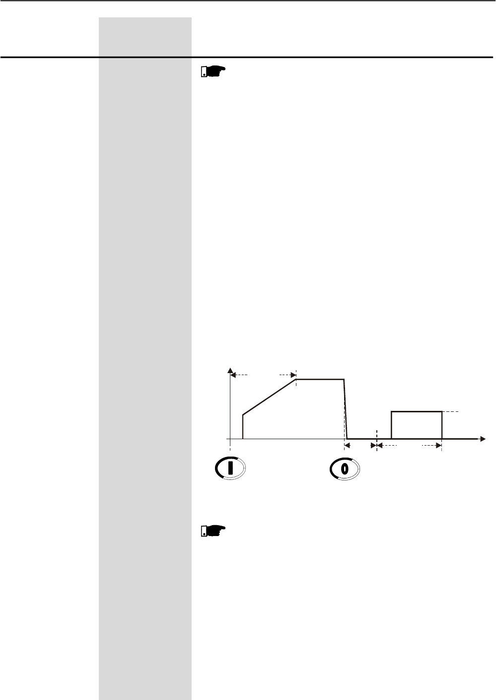
CHAPTER 6 - DETAILED PARAMETER DESCRIPTION
109
Range
[Factory Setting]
Parameter Unit Description / Notes
NOTES!
1. Use the digital input set to "General Enable" to stop the
motor without braking.
2. Use one digital input set to Braking Off, for extra safety, for
monitory the real motor standstill and disables the braking
immediately.
3. For high inertia loads it is recommended to use PTC motor
input.
4. It is not recommended the use of Optimal Braking with two
and eight pole motors.
5. See the parameters: P266, P267, P268, P500, P501, P502,
and P503 and see the recommended setup set-up at items
3.3 and 3.3.10
“DC-Braking”
This is an old and efficient method to stop very high inertia loads.
The direct current is applied all the time until the motor stops.
One contactor is needed to short-circuit two outputs output lines U
and V.
The necessary current to stop the motor is veryhigh and continuously
applied.
It is not compatible with the Soft-Starter SSW-06 inside delta motor
connection.
Figura 6.21 - DC-Braking
NOTES!
1. Use the digitalinput set to General Enable to stop the motor
without braking.
2. Use one digital input set to Braking Off, for extra safety, for
monitoring the real motor standstill and disables the braking
immediately.
3. It is recommended using a PTC motor input. Using a PTC
motor input is recommended
4. See the parameters: P266, P267, P268, P277, P278, P279,
P500, P501, P502, and P503 and see the recommended
setup set-up at items 3.3 and 3.3.11.
Start
U(V) 100%Un
Enable Disable
P502
t(s)
P501
DC-Brake RLX
Closed
1s
0Rotation direction K1 closed
CHAPTER 6 - DETAILED PARAMETER DESCRIPTION
110
Range
[Factory Setting]
Parameter Unit Description / Notes
P501 sets the maximum time that the braking voltage is applied.
ATTENTION!
1. This is the main protection of all braking methods. Set it
according to the application, since the Soft-Starter SSW-06
and the motor can withstand the settings.
2. The parameters: P001, P002, P003, P008, P009, P010 and
P011 are set to zero during Optimal Braking and DC-Braking.
3. The current protections do not work with a DC current
because the current transformers saturate with DC current.
4. The Soft-Starter SSW-06 does not protect the motor while it
is performing braking. while it is braking.
P501
Braking Time
1 to 299
[ 10 ]
1s
P502 sets the braking voltage level. It is based on theAC line voltage
converted to DC voltage.
This parameter also sets the level of theAC Reverse Braking.
ATTENTION!
1. Be careful with this voltage level. Set it according to the
application since the Soft-Starter SSW-06 and the motor
can withstand the settings.
2. Start with low voltage levels and increase it according to the
necessity. increase them according
3. The current protections do not work with a DC current
because the current transformers saturate with DC current.
4. The Soft-Starter SSW-06 does not protect the motor while it
is performing the braking. while it is braking.
5. To measure this current during the braking methods you
need a special current meters with hall effect transformers.
P502
Braking Voltage Level
30 to 70
[ 30 ]
%
P503
Braking End Detection
0 to 1
[ 0=Inactive ]
-
P503 Description
0 Inactive
1 Automatic
Table 6.33 - Braking End Detection
This parameter set sets the automatic detection of the motor standstill.
NOTES!
1. This function does not work with two and eight pole motors.
2. This function does not work with inside delta motor
connections.
3. The motor standstill detection can vary with the motor
temperature.
4. Always use the braking time as the main protection.
CHAPTER 6 - DETAILED PARAMETER DESCRIPTION
111
Range
[Factory Setting]
Parameter Unit Description / Notes
This parameter enables the fixed slow speed with Jog.
Slow speed with Jog forward foreward direction is about 1/7 of the full
speed.
Slow speed with Jog reverse direction is about 1/11 of the nominal
speed rated.
P510 (1)
Jog
0 to 1
[ 0=Inactive ]
-
P510 Action
0 Inactive
1 Active
Table 6.34 - Jog selection
Table 6.35 - Jog and motor direction of rotation
This parameter set sets the level of the torque torque level of the
slow speed with Jog.
This parameter sets the slow speed torque level with Jog.
ATTENTION!
1. Be careful with this torque level. Set it according to the
application since the Soft-Starter SSW-06 and the motor
can withstand the settings.
2. The motor can be enabled during a short period of time
with Jog. Connect a push-botton to a digital input to enable
the Jog.
3. The P102 parameter is the limit of time protection to the
Jog protection of the. If this time was exceed the fault E62
will actuate. If this time is exceeded, fault E62 will appear.
The P102 parameter is the time limit protection of the Jog.
If this time is exceeded, fault E62 will appear.
4. The parameters: P001, P002, P003, P008, P009, P010
and P011 are set to zero during the Jog Function.
5. The current protections do not work with the Jog current
because the current transformers saturate with the low Jog
frequency.
6. Soft-Starter SSW-06 does not protect the motor during a
Jog without the use of a PRC sensor on the motor.
7. To correctly measure the currents during the Jog, it is
necessary to use hall effect transformers.
P511
JogLevel
10 to 100
[ 10 ]
1%
P510 P231 Action
0 Inactive) - without Jog
1 (Active) 0 (Inactive) allows the slow speed with Jog only in forward
direction.
1 (Active) 1 (By Contactor) allows the slow speed with Jog in the same
direction of the power supply and the auxiliary
contactors connected at the input power
supply, changing the motor direction of
rotation.
1 (Active) 2 (JOG Only) allows the slow speed with Jog in both forward
and reverse directions without contactors.
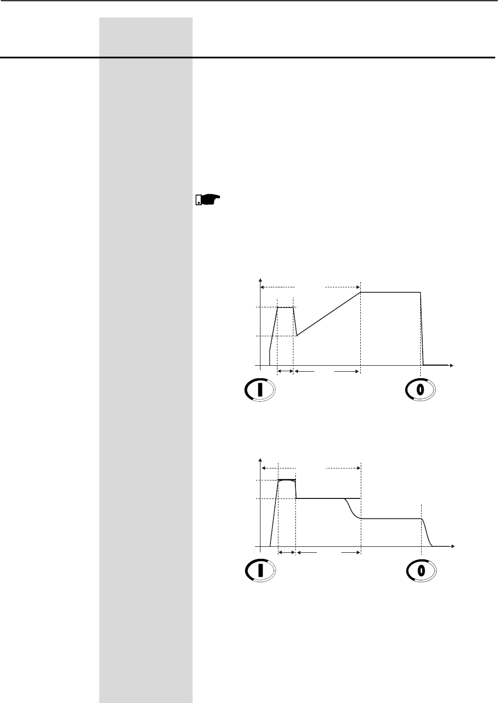
CHAPTER 6 - DETAILED PARAMETER DESCRIPTION
112
Range
[Factory Setting]
Parameter Unit Description / Notes
Soft-Starter SSW-06 allows for the use of a torque pulse during the
starting process for loads that have high resistance during the starting
process.
Enabled through P520=1. The duration of this pulse may be adjusted
at P521.
This pulse will be applied according to the type of control selected at
P202:
- Voltage ramp: the voltage level may be set at P522.
- Current limit: the current level may be set at P523.
- Current Ramp: with adjustable current level.
NOTES!
1) Use this function only for specific applications, when so
required.
2) This function is not required for the Torque Control.
P520 (1) 0 or 1
Torque Pulse [ 0=Inactive ]
at Start -
P521 0.1 to 2
Pulse Time [ 0.1 ]
at Start 0.1s
P522 70 to 90
Pulse Level of the [ 70 ]
Starting Voltage 1 %Un of the motor
P523 300 to 700
Pulse Level of the [ 500 ]
Starting Current 1 %In of the motor
Start
U(V) 100%Un
t(s)
P102
Disable
Enable Voltage Ramp
0
P101
P522
P521
Start
I(A)
I Limit
t(s)
P102
Disable
Enable Current Limit
0
P110
P523
P521
I Nominal
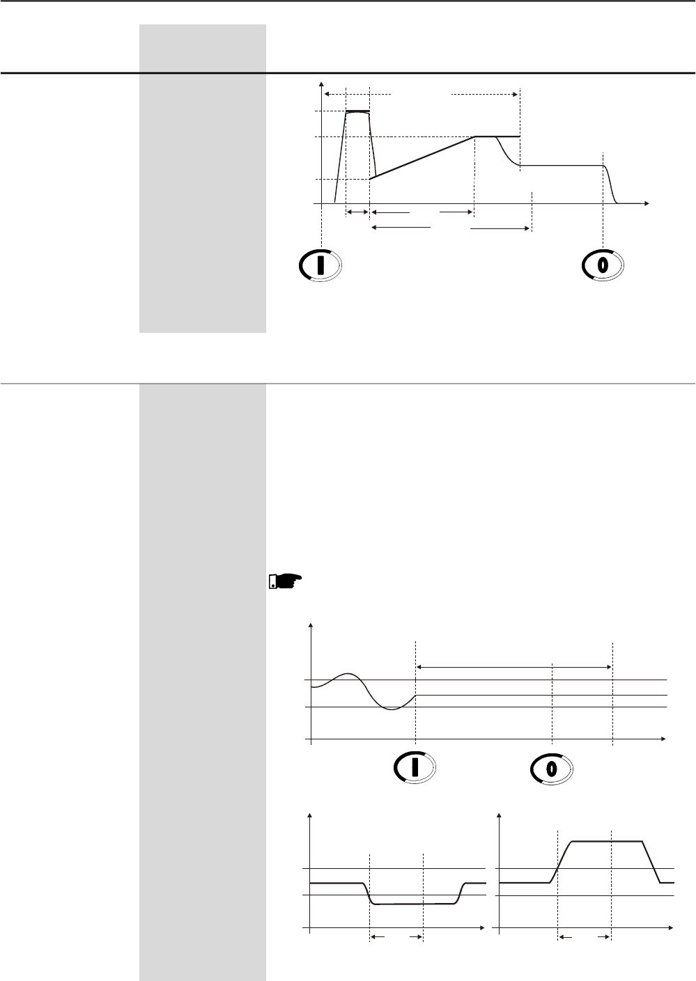
CHAPTER 6 - DETAILED PARAMETER DESCRIPTION
113
Range
[Factory Setting]
Parameter Unit Description / Notes
The under and overvoltage are setting as percentage of the motor
rated voltage (P400).
P600 sets the minimum voltage level at which the motor can operate
without problems. This protection function acts when the line voltage
drops to a value lower than the set and is present during a time equal
to or longer than those set at P601. If this condition is present, the
Soft-Starter is disabled and an Undervoltage Error is displayed.
P602 sets the maximum overvoltage level that the motor allows, during
the time that has been set at P603. If this time is exceeded, the
Soft-Starter is disabled and an Overvoltage Error is displayed.
NOTE!
These functions are active the entire time the motor is running.
P600 (1) 0 to 30
Intermediate [ 20 ]
Undervoltage 1 %Un of the Motor
P601 (1) 1 to 99
Time of Immediate [ 1 ]
Undervoltage 1s
P602 (1) 0 to 20
Intermediate [ 15 ]
Overvoltage 1 %Un of the Motor
P603 (1) 1 to 99
Time of Immediate [ 1 ]
Overvoltage 1s
6.7 PROTECTIONS PARAMETERS - P600 to P699
Figure 6.22 - Actuation Levels of the Starting Torque Pulse.
Start
I(A)
I Limit
t(s)
P102
Disable
Enable Current Ramp
0
P110
P523
P521
I Rated Current
Maximum Time
P112
P111
U(V)
Nominal
t(s)
Disable
Enable
0
P600
P602
Deceleration
ramp
Running
Actuation Region
U(V)
P602
P600
t0 P601 t1(s) t0 P603 t1(s)
Under
Voltage
Nominal
Fault
Action
Nominal
Over
Voltage
Fault
Action
Figura 6.23 - Actuation Levels in case of Undervoltage and Overvoltage
U (V)
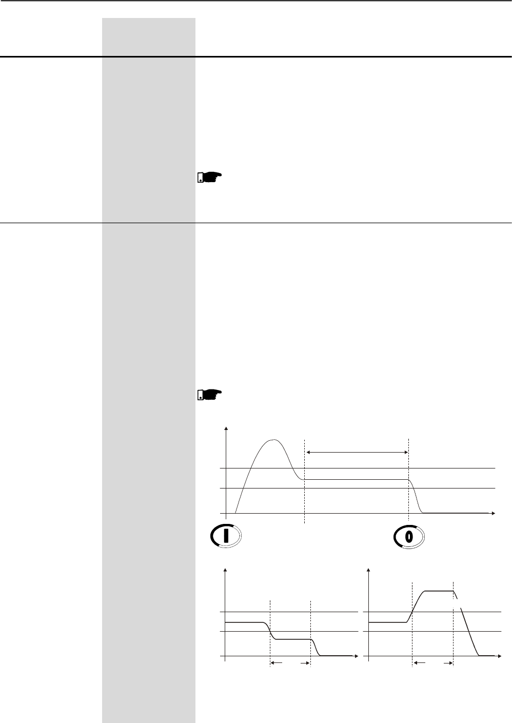
CHAPTER 6 - DETAILED PARAMETER DESCRIPTION
114
Range
[Factory Setting]
Parameter Unit Description / Notes
Time of Voltage Unbalance between phases is set as a percentage of
the motor rated current (P400).
P604 sets the maximum voltage difference between the three line
phases at which the motor can operate without problems, during the
time set at P605. If these values are exceeded, the Soft-Starter is
switched Off and the Voltage Unbalance error is displayed.
These settings also activate the phase fault protection during the
starting process and during the operation at full voltage.
NOTE!
This function is active always when motor is running.
P604 (1) 0 to 30
Voltage Unbalance [ 15 ]
between Phases 1%Un of the Motor
P605 (1) 0 to 99
Voltage Unbalance [ 1 ]
Between Phases 1s
Time
The Undercurrent and the overcurrent are set as percentage of the
motor rated current (P401).
P610 sets the minimum current level at which the motor can operate
without problems. This protection function acts when the motor current
drops below the value and during a time equal or longer than those
set at P611. If these values are exceeded, the Soft-Starter is switched
Off and the Undercurrent Error is displayed. This function is generally
used in applications with hydraulic pump which can not be operated
without a load.
P612 sets the maximum overcurrent levels that the motor or Soft-
Starter allows during the time set at P613, after which the Soft-Starter
is switched Off and the Overcurrent Error is displayed.
NOTE!
These Functions are onlyactive after the motor start and after full
voltage operation has been reached.
P610 (1) 0 to 99
Immediate [ 20 ]
Undercurrent 1%In of the motor
P611 (1) 1 to 99
Immediate [ 0=Inactive ]
Undercurrent Time 1s
P612 (1) 0 to 99
Immediate [ 20 ]
Overcurrent 1%In of the motor
P613 (1) 1 to 99
Immediate [ 0=Inactive ]
Overcurrent 1s
Time
Figure 6.24 - Actuation Levels for Overcurrent and Undercurrent
I(A)
0
P610
P612 Start
Nominal
DisableEnable
Actuation Region
t(s)
I(A)
t
P610
P612
t(s)
Nominal
Fault Action
Fault Action
I(A)
Nominal
t(s)
t
P611 P613
Under Current
Over Current
CHAPTER 6 - DETAILED PARAMETER DESCRIPTION
115
Range
[Factory Setting]
Parameter Unit Description / Notes
The current unbalance values are set as percentage of the motor rated
current (P401).
P614 sets the maximum current difference between the three motor
phases at which the motor can operate without problems, during the
time set at P615. If these values are exceeded, the Soft-Starter is
switched Off and the Current Unbalance error is displayed.
These settings also activate the phase fault protection during the
starting process and during the operation at full voltage.
NOTE!
This function is actuated only after motor start and after full voltage
operation has been reached.
This function, when enabled, ensures protection against undercurrent
before By-pass closing, i. and., preventing By-pass closing in case of
any supply line fault of any thyristor fault.
When this function is disabled, the motor can be started with rated
current lower than 10% of the rated Soft-Starter current.
NOTE!
This function can be disabled only when motors with low currents
are tested.
P616 (1) 0 or 1
Undercurrent before [ 1=Active ]
Internal By-pass -
Closing
P614 (1) 0 to 30
Current Imbalance [ 15 ]
between Phases 1 %In of the motor
P615 (1) 0 to 99
Current Imbalance [ 0=Inactive ]
between 1s
Phases Times
When this function is enabled it ensures protection against locked
rotor at the end of the start, i. and., it preventing that the By-pass
closes when an overcurrent two times the rated motor current is
detected.
NOTE!
Disable this function only when the motor can withstand loads
with higher currents.
P617 (1)
Motor Overcurrent
Before Internal
By-pass Closing
0 or 1
[ 1=Active ]
-
The function of this parameter is to protect loads that can be run only
in one direction of rotational. When this function is enabled, only the
phase sequence R/1L1, S/3L2, T/5L3 is permitted..
When this function is enabled, the phase sequence is detected every
time the motor is powered-up.
The function is very useful for driving of driving hydraulic pumps which
can be operated only in one direction of rotation.
P620 (1) 0 or 1
RST Phase [ 0=Inactive ]
Sequence
This function limits the minimum time interval between a new start
after the motor has been switched Off.
P630 2 to 999
Interval of Time [ 2 ]
after Stop 2s
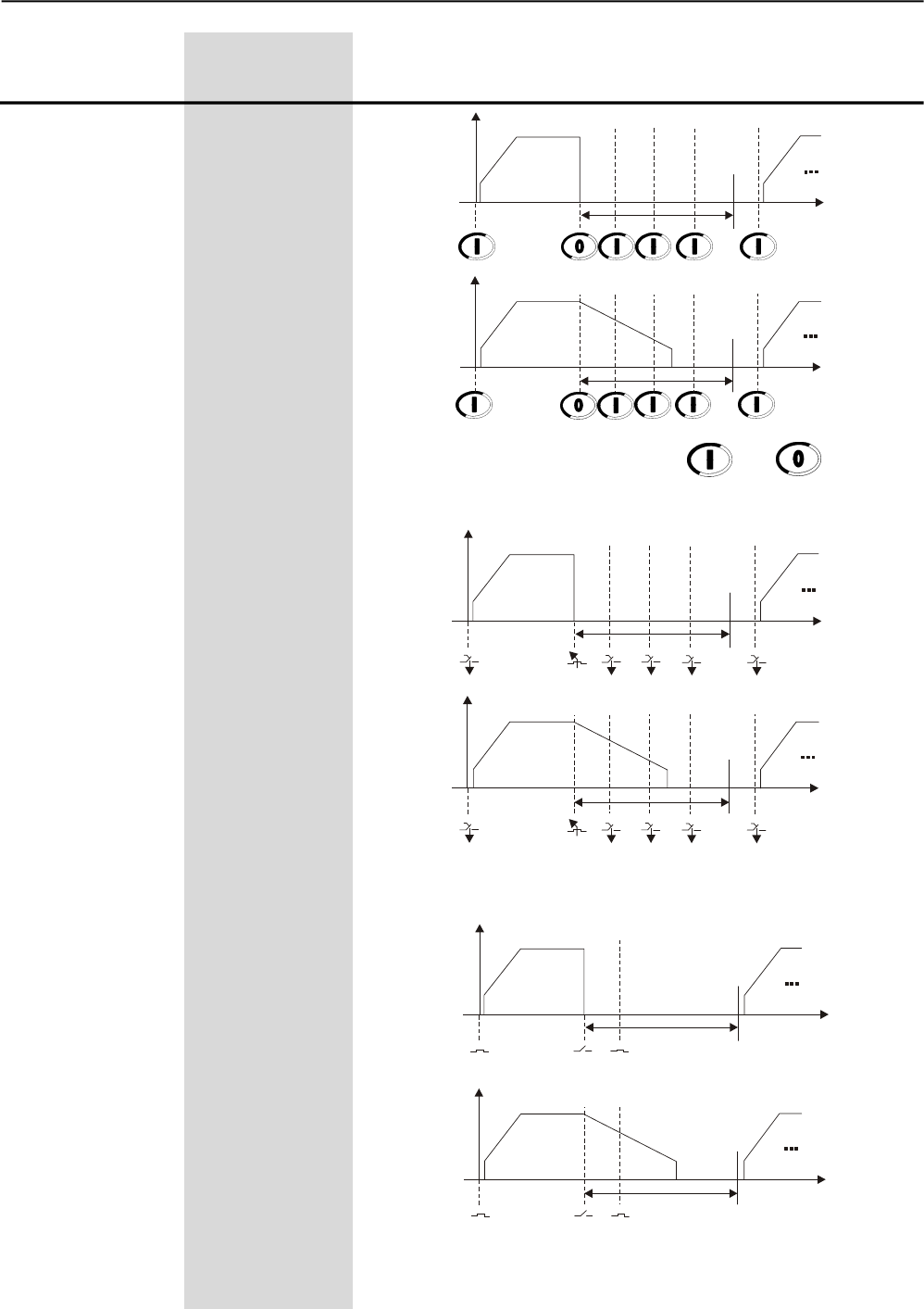
CHAPTER 6 - DETAILED PARAMETER DESCRIPTION
116
Range
[Factory Setting]
Parameter Unit Description / Notes
Figure 6.25 - Operation via HMI and .
Figure 6.26 - Operation via three-wire digital inputs (DI1 and DI2).
Figure 6.27 - Operation via digital input (DI1)
Un P104=0
P630=10s
Un P104=6s
P630=10s t
t
Un P104=0
P630=10s t
t
Un
P630=10s
Un P104=0
P630=10s t
t
Un
P630=10s
P104=6s
P104=6s
CHAPTER 6 - DETAILED PARAMETER DESCRIPTION
117
Range
[Factory Setting]
Parameter Unit Description / Notes
NOTE!
The start command will be executed only after the time interval
programmed at P630 has elapsed.
NOTES!
1) The time interval starts to be counted at the moment when the
motor switch Off command is given, indifferently if a deceleration
ramp has been programmed or no.
2) This function is only active when the time interval, which has
been set at P630, is longer than the time set at P104 for the
deceleration process, if programmed.
3) If the control board supply is removed, or if the microcontroller
is reset, no time counting occurs.
Soft-Starter SSW-06 has a rigid thermal protection that is efficient
and totally programmable for the protection of your motor. All Soft-
Starter SSW-06 models are fitted with this protection device. When
activated, error E05 (overload) will be displayed and the motor will be
switched off.
This thermal protection has curves that simulate the motor heating
and cooling. The calculation is executed by a complex Software, that
estimates the motor temperature through True RMS current supplied
to the motor.
The actuation curves of the Thermal Protection are based on
IEC 60947-4-2 standard.
The heating and cooling curves are based on WEG's extensive
experience with motor development. These curves adopt WEG three-
phase IP55 standard motors. Theyalso consider if the motor is cooled
or not when driven.
The cooling time of the thermal image depends on the motor power,
which means that each power will have different cooling time. When
reduction of this cooling time is required, you can use P641.
The estimated motor temperature is saved in non-volatile memory
every time the power supplyof the control board is switched off. Thus,
when the control board is switched on again, the last value saved will
return.
P640 (1) 0 to 9
Motor Protection [ 6=30 ]
Thermal Class 1
P640 Action
0 Inactive
1 Class 5
2 Class 10
3 Class 15
4 Class 20
5 Class 25
6 Class 30
7 Class 35
8 Class 40
9 Class 45
Table 6.36 - Thermal Classes
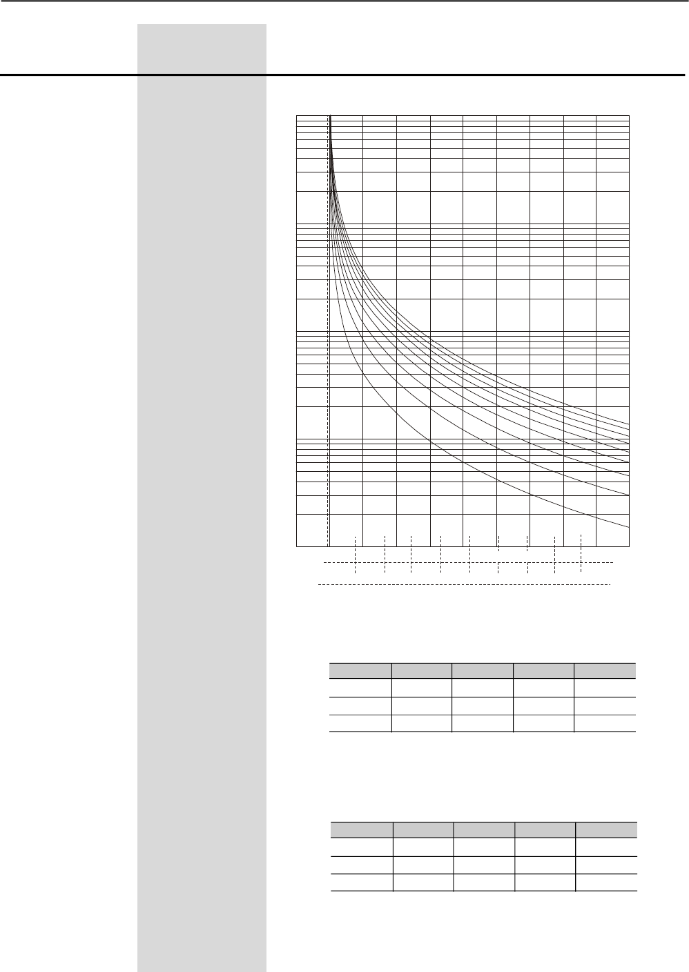
CHAPTER 6 - DETAILED PARAMETER DESCRIPTION
118
Range
[Factory Setting]
Parameter Unit Description / Notes
Figure 6.28 – Thermal Protection Classes for cold motor
Class 45
Class 40
Class 35
Class 30
Class 25
Class 20
Class 15
Class 10
Class 5
Current
x In
F.S.=1
F.S.=1,15
9x
9x
8x
8x 10x
7x
7x
6x
6x
5x
5x
4x
4x
3x
3x
2x
2x
1x
1x
1
10
100
1000
Time
t(s)
Class
3xIn
5xIn
7xIn
40
135s
48.1s
24.5s
30
101.2s
36.1s
18.3s
Table 6.37 – Thermal Protection Class Times for cold motor with S.F.=1.0
10
33.7s
12s
6.1s
20
67.5s
24s
12.2s
Table 6.38 – Thermal Protection Class Times for cold motor with S.F.=1.15.
Class
3xIn
5xIn
7xIn
40
180.2s
63.6s
32.4s
30
135.1s
47.7s
24.3s
10
45.1s
15.9s
8.1s
20
90.1s
31.8s
16.2s
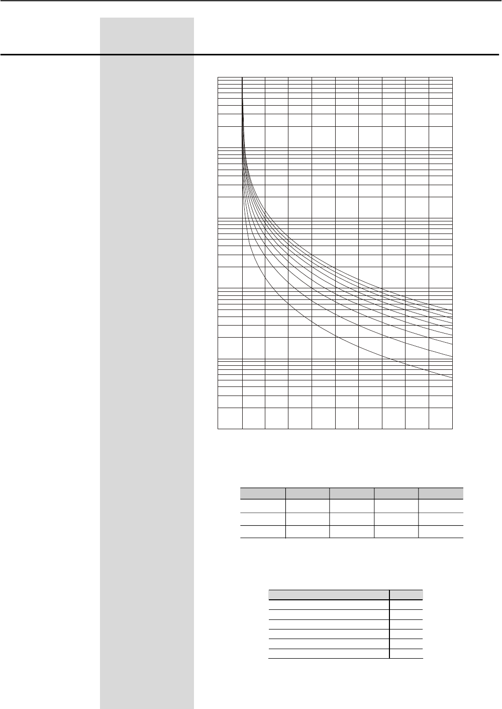
CHAPTER 6 - DETAILED PARAMETER DESCRIPTION
119
Range
[Factory Setting]
Parameter Unit Description / Notes
Table 6.39 - Thermal Protection Time for hot motor
Class
3xIn
5xIn
7xIn
40
47.2s
16.8s
8.5s
30
35.4s
12.6s
6.4s
10
11.8s
4.2s
2.1s
20
23.6s
8.4s
4.2s
Current in % of In of the Motor Factor
0%(cold) 1
20% 0,87
40% 0,74
60% 0,61
80% 0,48
100% (rated load) 0,35
Table 6.40 - Multiplication Factor of the Cold Thermal Classes Time to obtain
Hot Thermal Class Times
Figure 6.29 – Thermal Protection Classes for hot motor with 100% In
Class 45
Class 40
Class 35
Class 30
Class 25
Class 20
Class 15
Class 10
Class 5
Current
x In
9x
8x
7x
6x
5x
4x
3x
2x
1x
1
10
100
1000
Time
t(s)
0,1
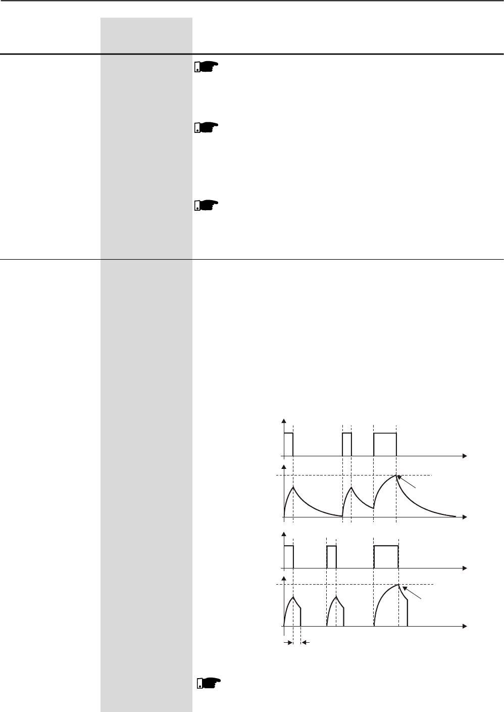
CHAPTER 6 - DETAILED PARAMETER DESCRIPTION
120
Range
[Factory Setting]
Parameter Unit Description / Notes
NOTE!
As there are several Thermal Protection Classes, you must
program that Thermal Protection Class that best meets you
application and protects the motor during its allowed duty.
NOTE!
The SSW-06 Soft-Starter thermal class times are an evolution of
the previous WEG soft-starters, therefore the times are different
than those of the SSW-03 and SSW-04. The class to be adopted
must be in accordance with the SSW-06 graphs.
NOTE!
When using a motor with a PTC thermal sensor or thermostat
entirely connected to the SSW-06 Soft-Starter, there is no need
to enable the Thermal Classes, therefore set P640=0.
Sets the time for the auto-reset of the thermal image of the motor.
This function can be used for applications that require several starts
per hour or those with short intervals of time between starting and
stopping the motor.
The motor cooling curves are based on many years of experience of
WEG developing motors. Theyadopt the Standard IP55Three Phase
Motors with temperature elevation of 60K as a standard. They also
consider if the motor is cooling when switched on or not.
The thermal image cooling time depends on the power of the motor, in
other words, for each power there is a different cooling time.
The thermal image can also be reset if parameter P640=0 is
programmed returning to the desired Thermal Class afterwards.
P641 (1) 1 to 600
Auto Reset of the [ 0=Inactive ]
Thermal Memory 1s
Motor
On
Off
Actuation
Level
Motor
On
Off
Actuation
Level
auto-reset
Time
with reset
E05
t
t
t
whithout
reset
E05
t
Figure 6.30 - Auto-reset of the thermal memory
NOTE!
Please consider that when using this function, the life time useful
life of the motor winding can be reduced.
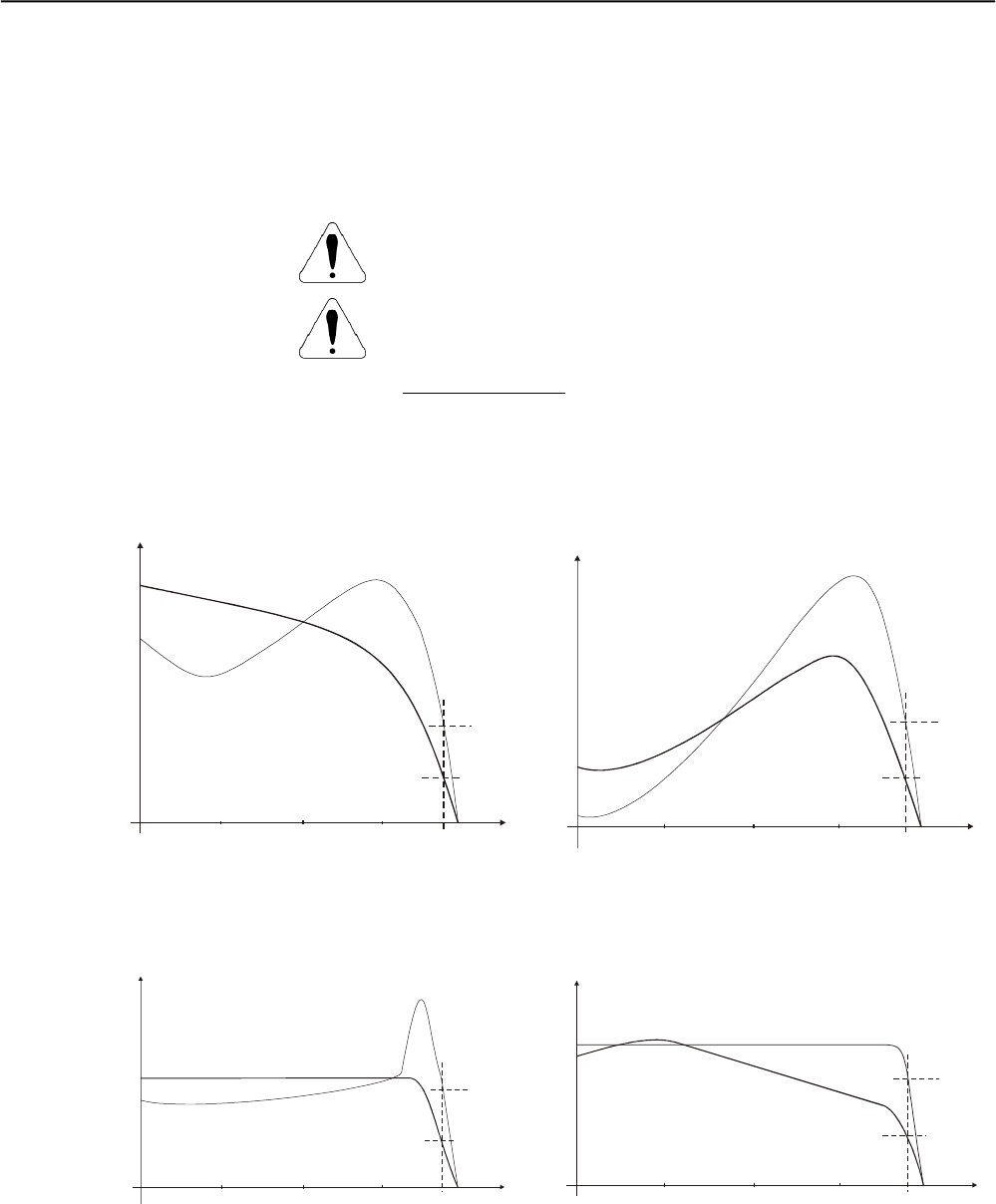
121
CHAPTER 7
7.1 APPLICATIONSAND
PROGRAMMING
Below are some suggested characteristic curves showing the
current and starting toque behavior byconsidering some load and
control types:
APPLICATIONS AND PROGRAMMING
This Chapter is useful for setting and programming the start control
type according to the application.
ATTENTION!
Important information about each start control type.
ATTENTION!
For correct parameter setting you must consider the load data and use
WEG Sizing Software, available at WEG Site
(http://www.weg.net).
If this site can not be accessed, you can follow some practical concepts
described below:
Although, if you cannot use it, a few practical principles are
described in this chapter.
Figure 7.1 – Characteristic torque and current curve in a direct on-line start and by Voltage Ramp
Figure 7.2 – Characteristic torque and current curves during a start with current Limit and Torque Control
I/In C/Cn
Current
Torque
Cn
In
025 50 75 100% rpm
025 50
I/In C/Cn
Current
Torque
Cn
In
025 50 75 100% rpm
I/In C/Cn
Current
Torque
Cn
In
025 50 75 100% rpm
I/In C/Cn
Current
Torque
Cn
In
025 50 75 100% rpm
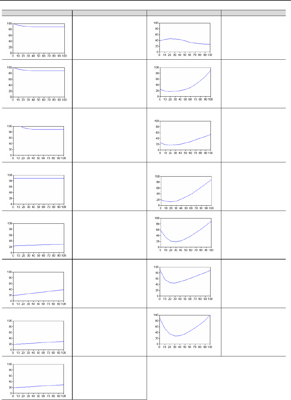
CHAPTER 7 - APPLICATIONS AND PROGRAMMING
122
Table 7.1 – Typical characteristics of staring torque curves of some load types with suggested types of control
Load Type Load Type Load Type Control Type
Alternative Pumps
3 Point Torque control
Screw Compressors
3 Point Torque control
Current Limit + K.Starter
Conveyor
3 Point Torque control
Current Limit + K.Starter
Axial Fans
Current Limit
Current Ramp
2 Point Torque control
3 Point Torque control
Extruders
Vertical Sand Mills
Wood Peeler
3 Point Torque control
Current Limit + K.Starter
Centrifugal Fans
Exhaust
Current Limit
Current Ramp
Piston Vacuum Pump
Piston Compressors
Constant Torque Control
Centrifugal Pumps
Vane Vacuum Pump
Pump Control
2 Point Torque control
3 Point Torque control
Crushers
Wood Peeler
Current Limit
Current Ramp
Submersible Centrifugal Pumps
3 Point Torque control
Centrifuges
Hammer Mills
Current Limit
2 Point Torque control
Ball Mill – Ceramics
Current Ramp + K.Starter
Current Limit + K.Starter
Barley – Starch Processing
Wood Chipper
Current Limit
Current Ramp
Mixers
Current Ramp + K.Starter
Current Limit + K.Starter
Cellulose Refiners
Voltage Ramp
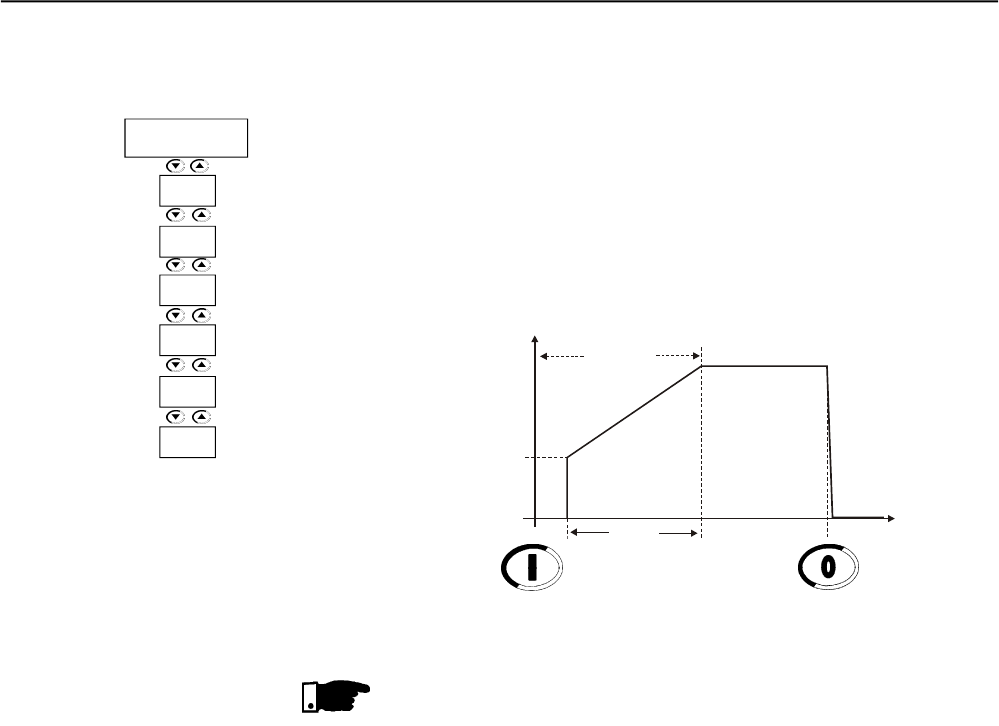
CHAPTER 7 - APPLICATIONS AND PROGRAMMING
123
7.1.1 Starting by Voltage Ramp
(P202=0)
1) Set initial voltage, P101. Set initially to a low value;
2) When load is applied to the motor, set P101 to a value that allows
motor running smoothly since the begin of its enabled;
3) Set P102 to the time required for the motor start. Set firstly short
time, 10 to 15 seconds, after try to find the most suitable starting
condition for your load.
Figure 7.3 – Starting by Voltage Ramp
NOTES!
1) Vibrations can occur during the load start, when long starting times
have been set, or motor is starting without load. In this case,
decrease the starting time;
2) If errors are detected during the motor start, check all connections
of the Soft-Starter to the power line, the motor connections, the
voltage levels of the power line, the fuses, circuit-breakers and
disconnecting switches.
U(V) Start 100%Un
P101
P102
0
Enable Voltage Ramp
t(s)
P102
P101
Voltage
Ramp
P640
P406
P401
P400
Disable
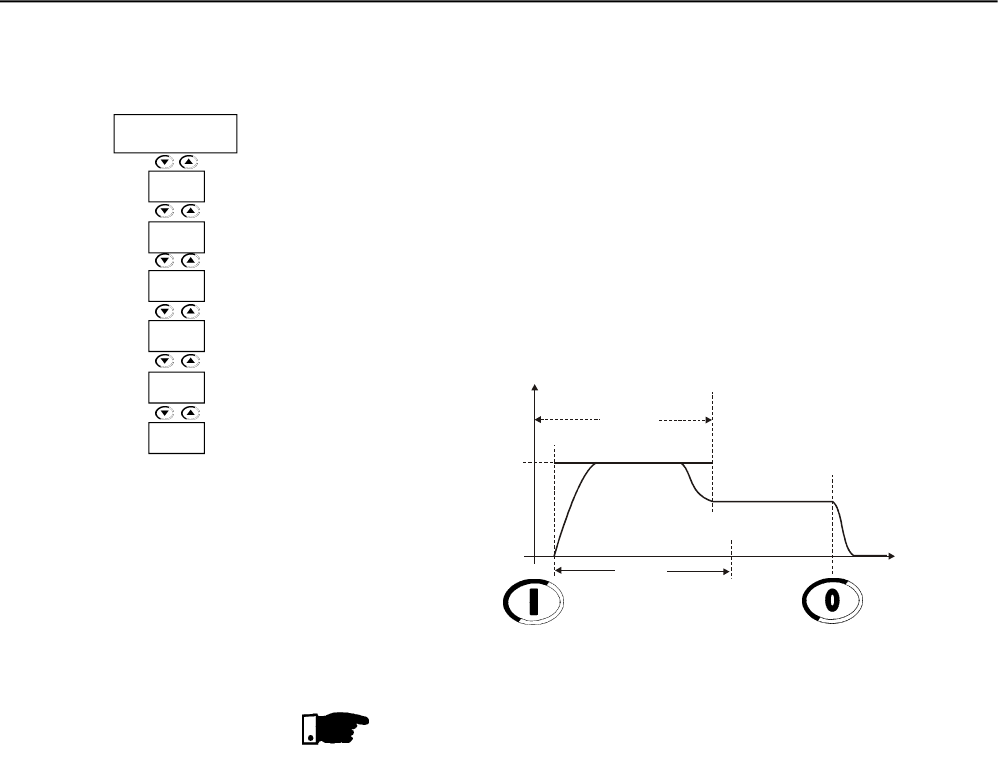
CHAPTER 7 - APPLICATIONS AND PROGRAMMING
124
7.1.2 Starting by Current Limit
(P202=1)
1) To start the motor with a current limit you must apply a load to the
motor. No-load tests can be done by voltage ramp;
2) Set P102 to the time required for the load start. At first set short
times, 20 to 25s. This time will be used as the locked rotor time,
when the motor is unable to start;
3) Set P110 with Current Limit by considering its electrical installation
and ensuring sufficient torque for the motor start. Initially you can
set firstly 2x to 3x the rated motor current (In of the motor).
Figure 7.4 – Starting by constant current limit
NOTES!
1) If the current limit is not reached during the starting, the motor will
start immediately.
2) P401 must be set according to the motor current;
3) Current Limits that are too low result in torques that are too low for
the motor start.Always maintain the motor running after it has been
enabled;
4) For loads requiring a higher initial starting torque, you can use the
kick start function, P520, or the current ramp method;
5) If errors are detected during the motor start, check all connections
of the Soft-Starter to the power line, the motor connections, the
voltage levels of the power line, the fuses, circuit-breakers and
disconnecting switches.
I(A)
Start
I Nominal
P110
P102
0
Enable Limit Current Disable
t(s)
I Limit
Maximum Time
P110
P102
Current
Limit
P640
P406
P401
P400
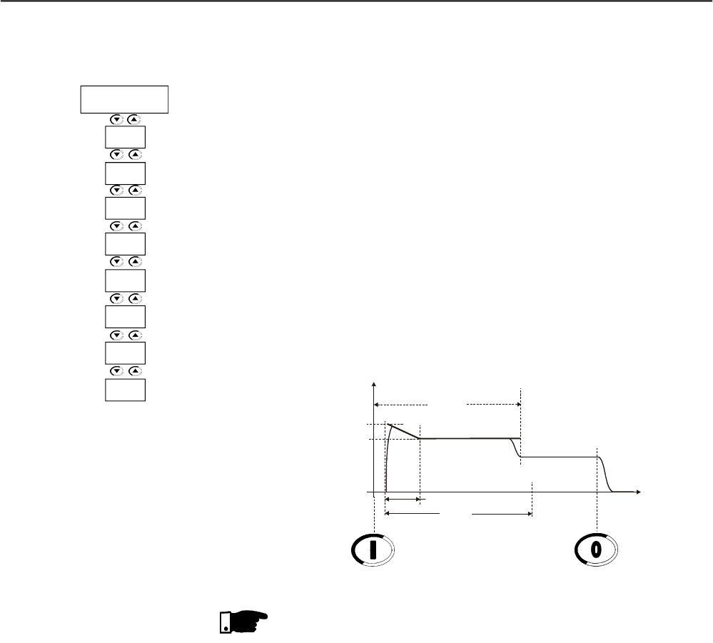
CHAPTER 7 - APPLICATIONS AND PROGRAMMING
125
7.1.3 Starting by Current Ramp
(P202=4)
1) For starting the motor with current ramp you must apply load on the
motor. No-load tests can be done by voltage ramp;
2) Use this function to help starting loads that require an higher initial
torque , as compressors and belt conveyors;
3) When such a load is started with fixed current limit, you can note
that the motor requires some time to start the load and then it
speeds up quickly;
4) As solution we recommend to set an initial current limit to overcome
the load start and then programming a current limit that enables the
load acceleration till the start end. In this way you certainly will
ensure a smooth start;
5) Set P111 to the current value required to start the motor;
6) Set P112 initially to 2s, i. and., to 10% of P102(20s) = 2s and then
increase it gradually;
7) The motor must run as soon as it is enabled;
8) Set P110 with current limit that maintains the motor accelerating.
Figure 7.5 – Starting with current ramp and initial higher current
NOTES!
1) If the current limit is not reached during the starting, the will motor
starts immediately.
2) P401 setting must be according to current of the used motor;
3) Alow Current Limit results in too low torque for the motor start.
Always maintain themotor always running after it has been enabled;
4) If errors are detected during the motor start, check all connections
of the Soft-Starter to the power line, the motor connections, the
voltage levels of the power line, the fuses, circuit-breakers and
disconnecting switches.
I(A)
Start
I Nominal
P110
P102
0
Enable Current Ramp Disable
t(s)
I Limit
Maximum Time
P111
P112
P110
P102
Current
Ramp
P401
P400
P112
P111
P640
P406
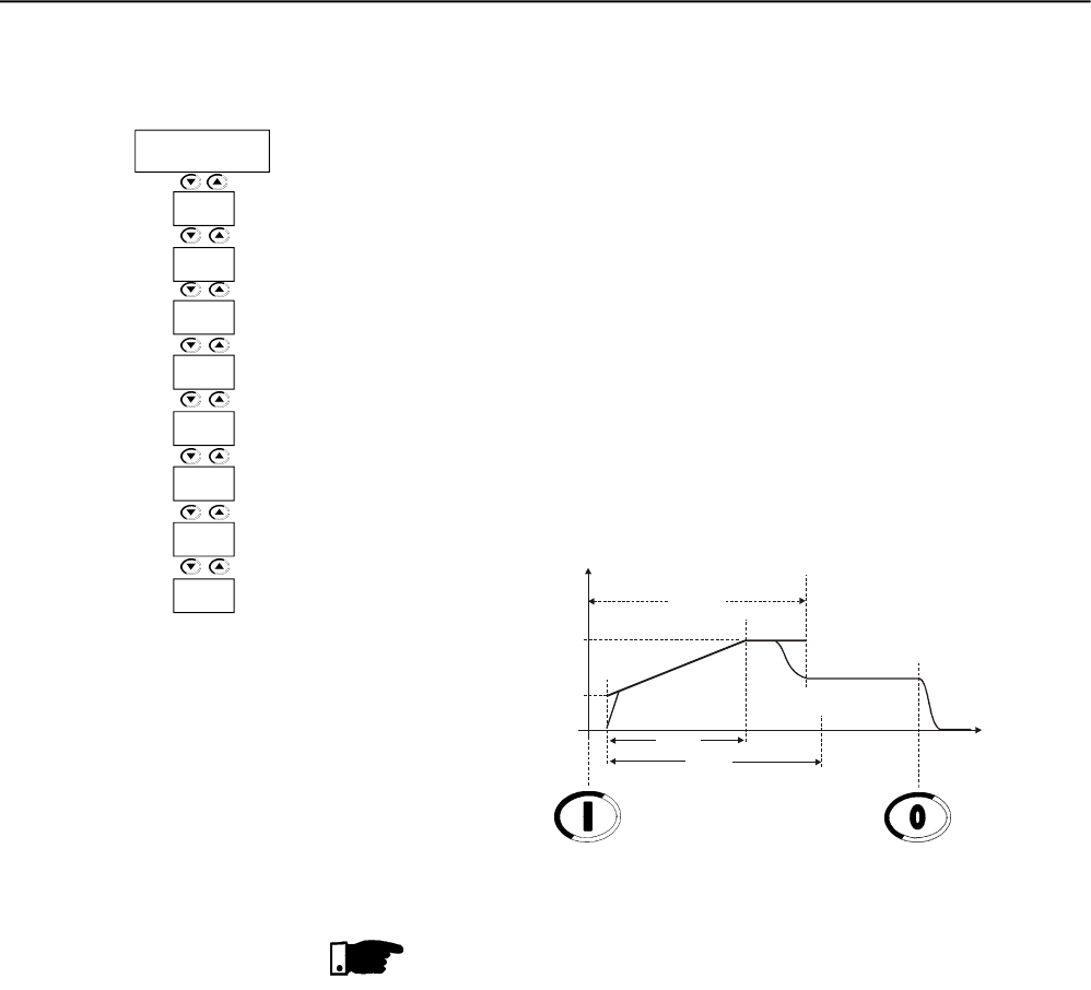
CHAPTER 7 - APPLICATIONS AND PROGRAMMING
126
7.1.4 Starting by Current Ramp
(P202=4)
1) To start the motor with current ramp you must apply load on the
motor. No-load tests can be done by voltage ramp;
2) Use this function to help starting loads that require a lower initial
torque, as fans and blowers;
3) When such a load is started with fixed current limit, you can note
that the motor starts the load and then it speeds up;
4) As solution we recommend setting a lower initial current to only run
the load and the increase the current limit graduallyuntil the end of
the start. In this way you will certainly ensure a smooth start;
5) Set P111 to the current value required to put the motor in movement
only;
6) Set P112 initially to 75% of P102(20s) = 15s and then increase it
gradually;
7) The motor must run as soon as it is enabled;
8) Set P110 with current limit that maintains the motor accelerating;
9) The motor must accelerate till the start end.
Figure 7.6 – Starting with current ramp and initial lower current
NOTES!
1) If the current limit is not reached during the starting, the motor will
start immediately.
2) P401 must be according to current of the used motor;
3) Current Limits that are too high result in torques that are too low for
the motor start.
Always maintain the motor running after it has been enabled;
4) If errors are detected during the motor start, check all connections
of the Soft-Starter to the power line, the motor connections, the
voltage levels of the power line, the fuses, circuit-breakers and
disconnecting switches.
I(A)
Start
I Nominal
P110
P102
0
Enable Current Ramp Disable
t(s)
I Limit
Maximum Time
P111
P112
P110
P102
Current
Ramp
P401
P400
P112
P111
P640
P406
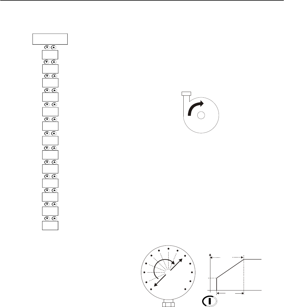
CHAPTER 7 - APPLICATIONS AND PROGRAMMING
127
7.1.5 Starting with Pump Control
(P202=2)
1) To start with pump control a load is necessary. Tests without a load
can be done with voltage ramp;
2) The parameter setting depends mainly of the types of hydraulic
installations. Thus we recommend to optimizing factory settings, if
possible.
3) Check if the motor rotation direction is an indicated on the pump
frame. If not, connect the phase sequence as indicated at P620;
Figure 7.7 – Direction of rotation of a hydraulic centrifugal pump
4) Set the initial voltage - P101 – so the motor starts smoothly as
soon as it is enabled.
5) Set the acceleration time according to its application, i. and., that
the motor is able to start the load smoothly, but the required
acceleration is not exceeded. If acceleration times are set too long,
this may result in vibration of harmful motor overheating;
6) To check the correct starting process, always use a manometer in
the hydraulic installation. Pressure increase should not result in
sudden oscillations. Thus the pressure increase should be as line-
ar as possible;
7) Program the voltage step during the deceleration process only when
no pressure drop is detected at the deceleration begin. With this
deceleration voltage step you can improve the pressure drop during
the deceleration process;
8) Set the deceleration time according to the application, i. and.,
ensuring that the pump stops smoothly within the expected limits.
The set of excessively long times mayresult in vibrations or harmful
motor overheating;
Figure 7.8 – Manometer showing pressure increase
Enable
P102
Pump Control
0
P101
U(V) Start 100%Un
P611
P610
P401
P400
Pump
Control
P105
P104
P103
P102
P101
P130
P640
P406
P620
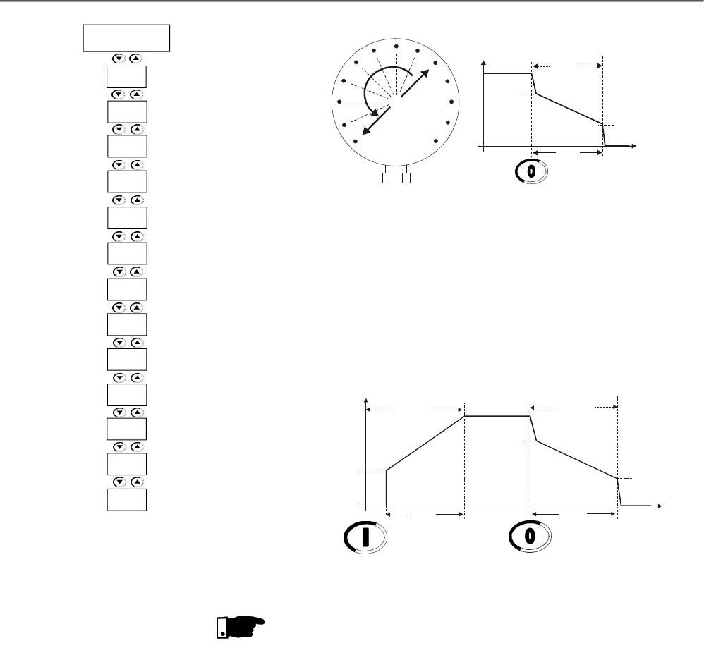
CHAPTER 7 - APPLICATIONS AND PROGRAMMING
128
Figure 7.9 – Manometer showing the pressure drop
9) Generally, the current increases at the end of the deceleration ramp
and in this casethe motor requires more torque to achieve a smooth
water flow stop. When the motor has already stopped, but is still
enabled, the current willincrease too much. To prevent this condition,
set P105 to a value that as soon it stoop it is also disabled;
10)Set P610 and P611 to current and time levels that prevent the
hydraulic pump from running without a load.
NOTES!
1) P400 and P401 must be set according to the line voltage and the
rated current of the used motor used;
2) If the hydraulic piping is not fitted with manometer, the hydraulic
rams can be noted at the pressure relief valves;
3) Please consider, that sudden line voltage drops results in motor
torque drops. Thus, ensure that the power supply line characteristics
are within the characteristics required for motor operation;
4) If errors are detected during the motor start, check all connections
of the Soft-Starter to the power line, the motor connections, the
voltage levels of the power line, the fuses, circuit-breakers and
disconnecting switches.
Figure 7.10 – Start with pump control
U(V) Start Stop
P101
P102
0
Enable Disable
t(s)
100%Un
Pump Control
P103
P104
P105
Disable
P104 t(s)
0
P103
U(V) Stop
100%Un
P105
P611
P610
P401
P400
Pump
Control
P105
P104
P103
P102
P101
P130
P640
P406
P620
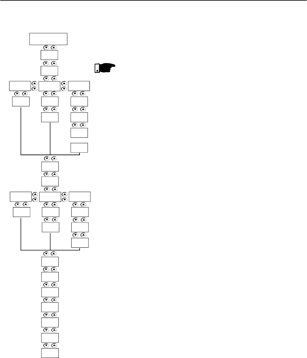
CHAPTER 7 - APPLICATIONS AND PROGRAMMING
129
7.1.6 Starting with Torque Control
(P202=3)
1) Thetorque control of the Soft-Starter SSW-06 demonstrates excellent
performance during motor and load starts;
2) This control is available in a form to facilitate and to adjust the type
of control to the type of load;
3) See below some recommendations on how to program and set this
type of control.
NOTES!
1) To start with pump control a load is necessary. Tests without a load
can be done with voltage ramp.
2) If the torque limits are not reached during the start, the motor will
start immediately.
3) Only use the control type and/or torque control type you are able to
set. Always select the control type that is easier to set, considering
the load characteristics;
4) When heavy loads are started, always select the start by current
limit. In this way you can set the energy consumption during the
start by considering the power line capacity;
5) All motor parameters must be set according to the motor nameplate,
P400 to P406;
6) Torque limits that are too low do not supply enough torque to start
the motor;
7) Low torque limits are also very sensitive to motor temperature
oscillations, for instance when load is started with cold or hot mo-
tor;
8) Low torque limits are also very sensitive to load changes, for
instance, oils, greases and relief valves have different resistant
torques in relation to the motor start when they are hot or cold;
9) Always maintain motor running after is has been enabled, indifferent
if it has been started cold or hot;
10)The motor manufacturer supplies the maximum torque developed
by the motor, during the starting or at full load. The Soft-Starters
can only limit these this data;
11)If errors are detected during the motor start, check all connections
of the Soft-Starter to the power line, the motor connections, the
voltage levels of the power line, the fuses, circuit-breakers and
disconnecting switches.
Torque
Control
P120
P102
Constant Linear Quadratic
P123
P122
P121
P122
P121
P121
P124
Constant Linear Quadratic
P128
P127
P126
P127
P126P126
P402
P401
P400
P406
P405
P404
P640
P104
P125
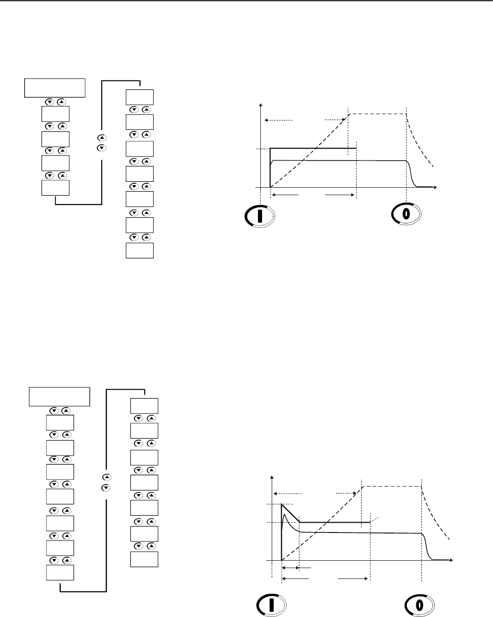
CHAPTER 7 - APPLICATIONS AND PROGRAMMING
130
7.1.6.1 Loads with constant torque
(P202=3 and P120=1
point)
1) Set P121 as percent of the rated motor torque, necessary for the
motor + load during running process;
2) Set P102 to the time required for the motor start. Firstly program
short times: 10 to 15s;
3) With the torque control you can start the load smoothly within short
starting times due to the linearity of the start speed ramp.
Figure7.11 – Start with constant torque control - 1 point
7.1.6.2 Loads with initial high
torque (P202=3 and
P120=3 points)
1) Through this function you can achieve a smooth and linear starting
ramp. This function is very useful for driving belt conveyors;
2) Through the load curve you can set a starting torque 10% to 20%
higher than the load torque for each one of the points P121, P123,
P122 and the times at P102 and P124;
3) For the first start you can use a speed measuring instrument, thus
ensuring the desired acceleration or the desired speed curve;
4) If no load curves are available, you can apply a similar method as
the current ramp method. Also the torque limit, P120=1, can be
used for executing the first start-ups and afterward changing to this
function.
Figure 7.12 – Starting with quadratic torque control, 3 points,
with higher initial load
Tn(%)
Start
Speed
P102
0
Enable Disable
t(s)
Maximum Time
P121 Tn Nominal
Load Torque
Torque Control
P120 =1
P102
Torque
Control
P401
P400
P104 =0
P121
P640
P406
P404
P402
P405
Tn(%)
Start
Speed
P124
0
Enable Disable
t(s)
Maximum Time
P121
Tn Nominal
Load Torque
Torque Control
P123
P102
P122
P120 =3
P102
Torque
Control
P401
P400
P122
P121
P640
P406
P404
P402
P405
P123
P124
P104 =0
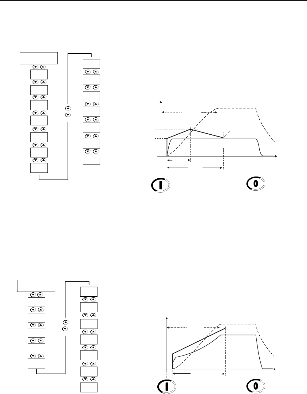
CHAPTER 7 - APPLICATIONS AND PROGRAMMING
131
7.1.6.3 Loads with constant torque
and S speed curve
(P202=3 and P120=3
points)
1) Through the load curve you can set the torque 10% to 20% higher
than the load torque for the initial and the end points, P121 and
P122, are 30% to 40% higher than load torque for the middle point
P123;
2) Maintain P124 between 45% to 55% and set P102 according to the
starting time;
3) For the first start you can use a speed measuring instrument, thus
ensuring the desired acceleration or the desired speed curve;
4) If no load curve is available, but you are sure that the torque is
constant, you can use the torque limit, P120=1 for executing the
first start-ups and changing to this function afterwards.
Figure 7.13 – Starting with quadratic torque control, 3 points, with constant load
7.1.6.4 Loads with quadratic torque
and S speed curve
(P202=3 and P120=2
points)
1) Through the linear torque ramp you can obtain a speed curve
very similar to a S-curve with quadratic load, but not very steep;
2) Through the load curve you can set the torque 10% to 20% higher
than the load torque for the initial point P121, and 20% to 30%
than the load torque for the end point, P122;
3) If no load curves are available, proceed as follows:
3.1) Set P121 to the required torque to run the motor + load;
3.2) Set P122 to 110% to 130% of the rated motor torque;
3.3) First set P102 firstly to low values, 10s to 15s and then increase
these values.
Figure 7.14 – Starting with linear torque control, 2 points, quadratic load
Tn(%)
Start
Speed
P124
0
Enable Disable
t(s)
Maximum Time
P121 Tn Nominal
Load Torque
Torque Control
P123
P102
P122
P120 =3
P102
Torque
Control
P401
P400
P122
P121
P640
P406
P404
P402
P405
P123
P124
P104 =0
Tn(%)
Start
Speed
0
Enable Disable
t(s)
Maximum Time
P121
Tn Nominal
Load Torque
Torque Control
P102
P122
P401
P400
P640
P406
P404
P402
P405
P120 =2
P102
Torque
Control
P122
P121
P104 =0
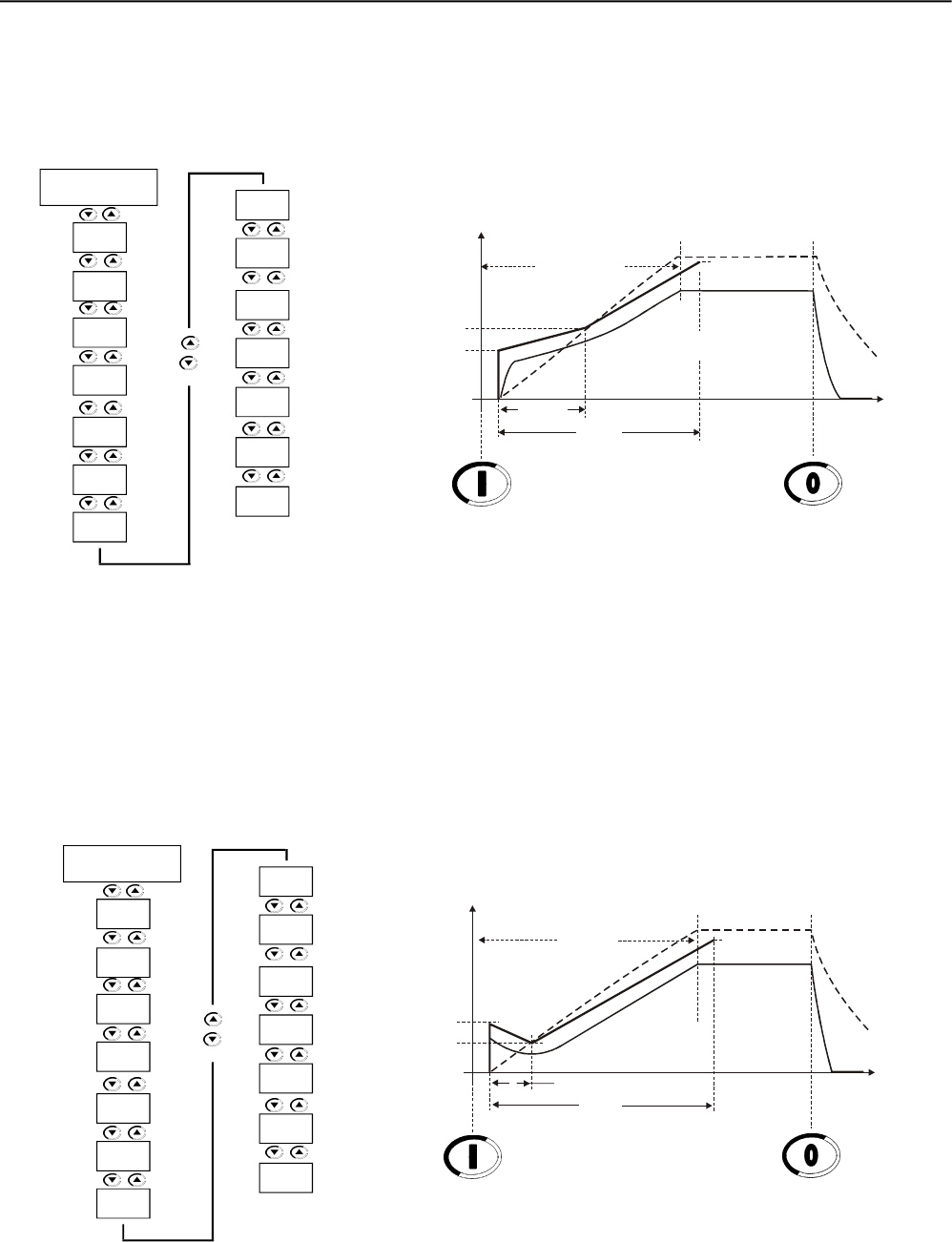
CHAPTER 7 - APPLICATIONS AND PROGRAMMING
132
7.1.6.5 Loads with quadratic torque
and linear speed curve
(P202=3 and P120=3
points)
1) Through a steep quadratic load you can set an intermediate point
for improving the linearityof the start speed curve;
2) Through the load curve you can set the torque 20% to 30% higher
than the load torque for all points P121, P123 and P122 and set
P124 as a percent of the time for the intermediate point
3) If no load curves are available, set it initially with a linear torque,
P120=2 points, and afterward set the intermediate time and torque.
Figure 7.15 - Starting with quadratic torque control, 3 points, quadratic load
7.1.6.6 Loads with quadratic torque
and higher initial torque
(P202=3 and P120=3
points)
1) With a very steep quadratic load, very high initial torque, you can
set an intermediate point for improving the linearity of the startspeed
curve;
2) Through the load curve you can set the torque 20% to 30% higher
than the load torque for all points P121, P123 and P122 and set
P124 as a percent of the time for the intermediate point;
3) If no load curves are available, set it initially with linear torque,
P120=2 points, and afterward set the intermediate time and torque.
Figure 7.16 - Starting with quadratic torque control, 3 points, quadratic load with
higher initial torque
Tn(%)
Start
Speed
P124
0
Enable Disable
t(s)
Maximum Time
P121
Tn Nominal
Load Torque
Torque Control
P123
P102
P122
Tn(%)
Start
Speed
P124
0
Enable Disable
t(s)
Maximum Time
P121
Tn Nominal
Load Torque
Torque Control
P123
P102
P122
P120 =3
P102
Torque
Control
P401
P400
P122
P121
P640
P406
P404
P402
P405
P123
P124
P104 =0
P120 =3
P102
Torque
Control
P401
P400
P122
P121
P640
P406
P404
P402
P405
P123
P124
P104 =0
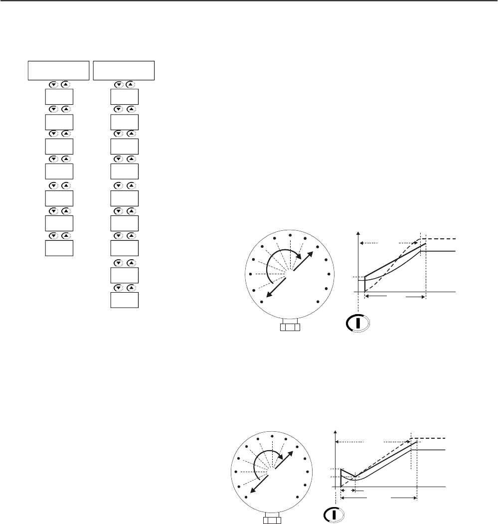
CHAPTER 7 - APPLICATIONS AND PROGRAMMING
133
7.1.6.7 Hydraulic pump load type
(P202=3)
Starting (P120=2 or P120=3):
1) Before any setting, carefully read carefully the steps described in
Starting with Pump Control, item 7.1.5;
2) If the pump control does not meet your requirements our if a
control with better performance is desired, use the torque control;
3) With a linear torque ramp you can obtain a speed curve very
similar to the S-Curve with quadratic loads, as centrifugal pumps;
4) Through the load curve you can set the torque 10% to 20% higher
than the load torque for the initial point P121, and 20% to 30%
higher than the load torque for the end point, P122;
5) Even when the load curve is used, we recommend executing a
setting at the application field. For this, proceed as follows:
5.1) Set P121 to the torque required for the running pump;
5.2) Set P122 to 110% to 130% of the rated motor torque;
5.3) Set P102 initially to lower values, 10s to 15s, then increase this
setting.
7) The main purpose of the two above mentioned cases is maintaining
the pressure ramp as linear as possible, increasing it gradually;
8) As already described in the pump control, the use of a measuring
instrument is required for measuring this pressure and soobtaining
the best setting;
Figure 7.17 – Manometer showing the pressure increase, linear torque
6) If the load has a higher initial torque, could be used the quadratic
torque (P120=3 points);
Figure 7.18 – Manometer showing the pressure increase, quadratic torque
Tn(%)
Start
P121
0P102
MaximumTime
Torque Control
Enable
Load Torque
Tn Nominal
Speed
P122
Tn(%)
Start
P121
0
P102
Torque ControlEnable
Load Torque
Tn Nominal
Speed
P122
P123
MaximumTime
P124
P120 =3
Torque
Control
P122
P123
P104 0
P124
P120 =2
P102
Torque
Control
P122
P121
P104 0
P126
P125 =1
P102
P121
P126
P125 =1
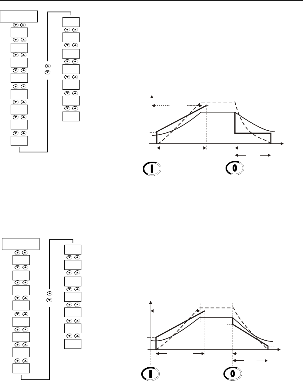
CHAPTER 7 - APPLICATIONS AND PROGRAMMING
134
Stopping (P1240 and P125=1):
1) In most applications only the constant toque control can be used for
pump stopping, 1 point=constant;
2) This method is used for water columns that are not very high;
3) Set P126 initially to the same value of P121, provided it is correct;
4) Set P126 in such a way that at the end of the pump stopping process
the motor is not still enabled;
5) As soon as the pump is disabled, a gradual pressure drop should be
noted without significant pressure oscillation, mainly at the end of the
stop, when the retaining valve is closed.
Figure 7.19 – Hydraulic pump stopping with constant torque, 1 point
Stopping (P1240 and P125=2):
1) Linear deceleration torque, 2 points=linear;
2) Applied to high water columns;
3) At first you can set P126 for 10% to 15% lower than the value of P121,
provided this value is correct;
4) Set P127so that when the beginning of the stopping process, the pressure
decreases gradually and no sudden pressure oscillation occurs;
5) Set P126 so that at the end of the pump stopping process the motor is
not still enabled.
Figure 7.20 – Hydraulic pump stopping with linear torque, 2 points
Tn(%)
Start
Speed
0
Enable Disable
t(s)
Maximum Time
P121
Tn Nominal
Load Torque
Torque Control
P102
P122
P128
P104
P126
P401
P400
P640
P406
P404
P402
P405
P120 =2
P102
Torque
Control
P122
P121
P104 0
P125 =1
P126
P127
Tn(%)
Start
Speed
0
Enable Disable
t(s)
Maximum Time
P121
Tn Nominal
Load Torque
Torque Control
P102
P122
P128
P127
P104
P126
P401
P400
P640
P406
P404
P402
P405
P120 =2
P102
Torque
Control
P122
P121
P104 0
P125 =2
P126
P127
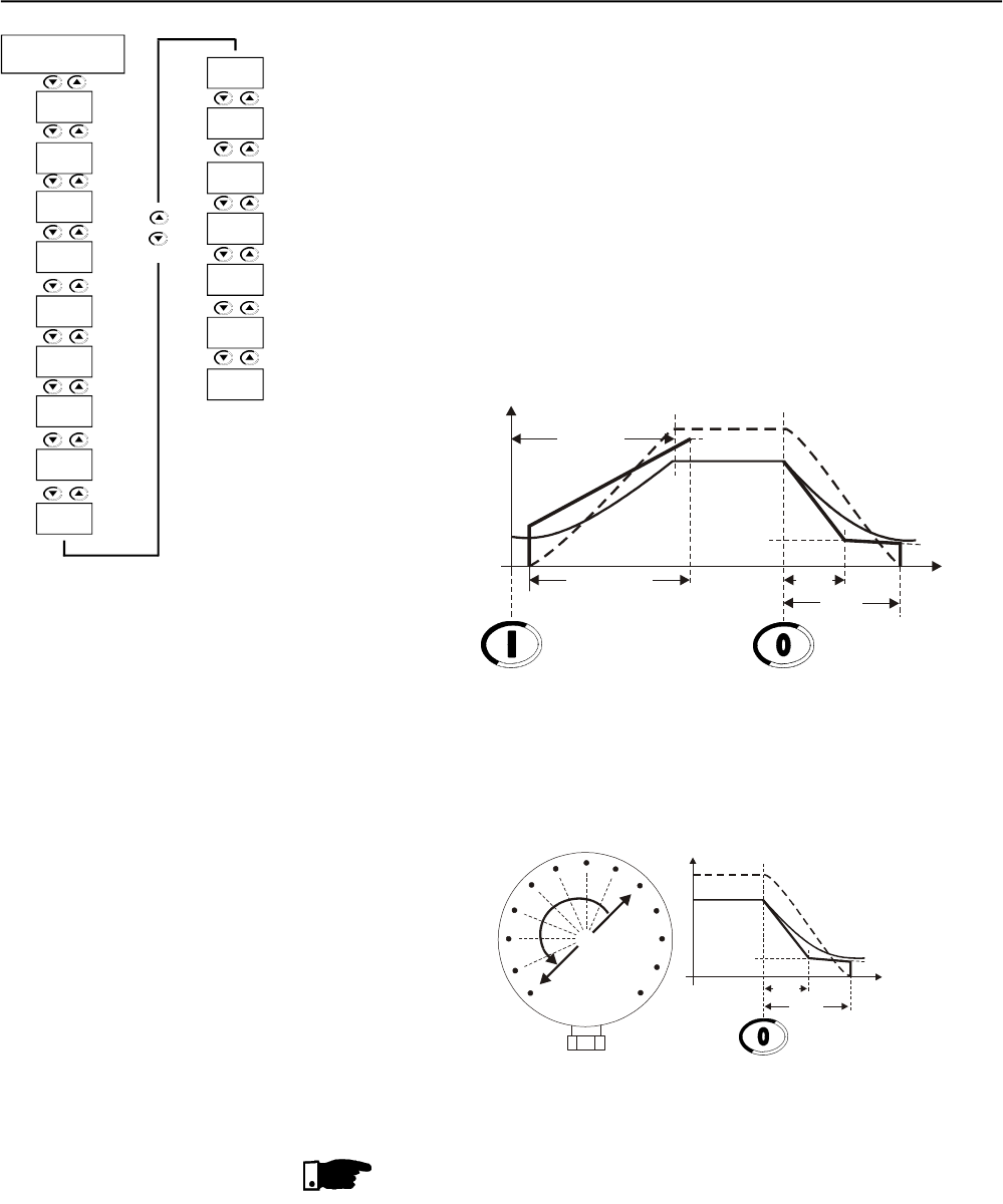
CHAPTER 7 - APPLICATIONS AND PROGRAMMING
135
Stopping (P1240 and P125=3):
1) Quadratic deceleration torque, 3 points=quadratic;
2) Applied to high water columns with high pressures;
3) This control is used when it is difficult to achieve a gradual pressure
drop without sudden pressure oscillations, mainlyat the start of the
stopping process;
4) The best way to perform this is to use the load curve as a base and
set the 3 points 10% to 15% lower;
5) Set P128 initially to 50%;
6) Set P127 so that at the beginning of the stopping process, the
pressure decreases gradually and no sudden pressure oscillation
occurs;
7) Set P126 so that at the end of the pump stopping process the motor
is not still enabled.
Figure 7.21 – Hydraulic pump stopping with quadratic torque, 3 points
8) If the load shows a higher initial torque, then usethe quadratic torque
control (P120=3 points).
Figure 7.22 – Manometer showing the pressure drop, torque control
NOTES!
1) The main purpose of the torque control types applied to the stopping
process is to maintain the drop in the pressure ramp as linear as
possible, decreasing the pressure gradually and thus preventing
sudden pressure oscillation, at the beginning, middle and at the end
of the stopping process;
2) As already described in the pump control, the use of a measuring
instrument is required to measure the pressure and obtain the best
setting;
3) Remember: constant torque control is suitable for the greatest number
of applications and its use is very easy.
Tn(%)
Start
Speed
P128
0
Enable Disable
t(s)
Maximum Time
P121
Tn Nominal
Load Torque
Torque Control
P102
P122
P104
P126
P127
%Tn
0
P104
Tn Nominal
Speed
P127
P128
P126
t(s)
Disable
P401
P400
P640
P406
P404
P402
P405
P120 =2
P102
Controle
de Torque
P122
P121
P104 0
P125 =3
P126
P127
P128
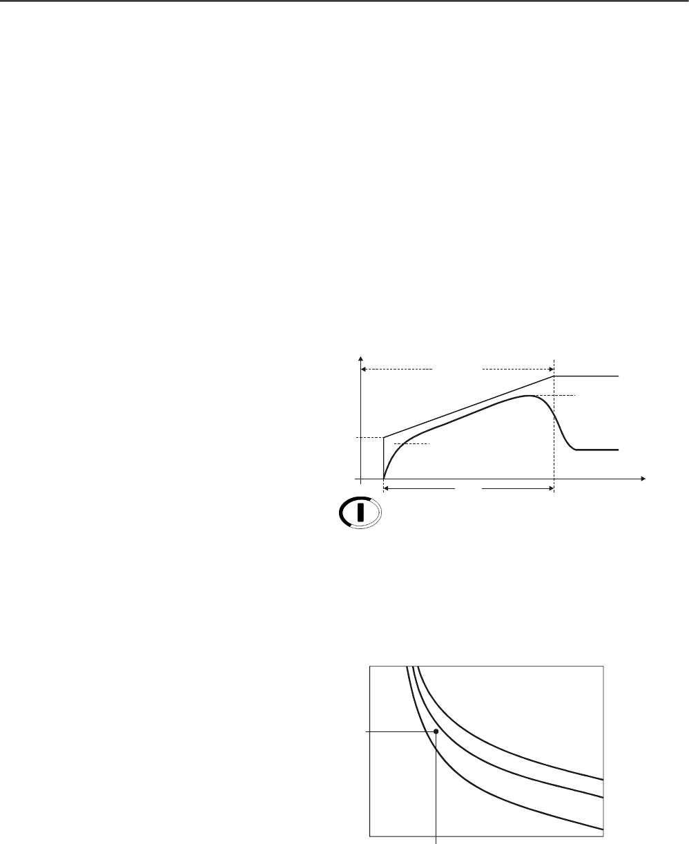
CHAPTER 7 - APPLICATIONS AND PROGRAMMING
136
1) Initiallystart from the standard thermal class, sometimes, but without
heating the motor excessively.
2) Determine the correct starting time. Find an average of the current
through the P002 during the starting time. One can find a current
average for any kind of starting control.
For example:
When an 80A motor is started by voltage ramp, the current at P002
starts at 100A and increases to 300A and after 20s drops to the
rated current.
(100A+300A)/2 = 200A
200A/80A = 2.5 x In of the motor
then: 2.5 x In @ 20s.
7.2 PORTECTIONSAND
PROGRAMMING
7.2.1 Thermal Classes
7.2.1.1 Suggestions about thermal
class setting
Figure 7.23 – Typical current curve when started by voltage ramp
3) Use this time to find the minimum class necessary to start a cold
motor according to the descriptions of the P640 in chapter 6;
Figure 7.24 – Determining the minimum thermal class with cold motor
Thus the minimum required thermal class for starting the motor is the
Class 10. The Class 5 requires a shorter time for this current.
This Thermal Class allows motor cold start.
U(V) Start 100%Un
20s
0
Enable
t(s)
P101
Voltage Ramp
P102
Current
in P002
100A
300A
t(s)
0
20s
2.5 x In of the Motor
5
10
xln
15
Cold
F.S.=1
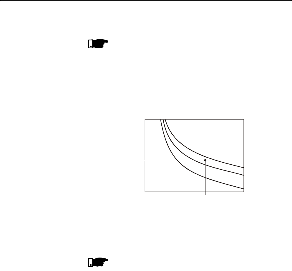
CHAPTER 7 - APPLICATIONS AND PROGRAMMING
137
4) To determine the thermal class for starting the motor at running
condition (hot), the motor thermal class must be known. For this we
must determine the allowed locked rotor time.
NOTE!
To program the Thermal Class that your motor will withstand, the allowed
locked rotor time must be available. For this data, please refer to the
manufacturer catalog.
With the blocked rotor time we can find the maximum thermal class
that will protect the motor for hot starter, according to the descriptions
of the P640;
For example:
6,6 x In @ 6s
Figure 7.25 – Determining the maximum thermal classes through the hot
starting curves
Thus, the maximum thermal class that will protect the motor is Class
35, Class 40 has too long a time for this current.
This thermal class allows the motor to start at running condition (hot),
in other words, it can be started in any condition.
NOTE!
Please consider that this protection adopts WEG standard three-phase
IP55 motor as a standard. Thus, if your motor is different, do not program
the maximum allowed thermal class, but program the thermal class
near the minimum thermal class required for the start.
Motor Data:
Power: 50 HP
Voltage: 380V
Rated current (In): 71A
Service Factor (S. F.): 1.00
Ip/In : 6.6
Locked rotor time:12s at hot
Speed = 1770 rpm
Data about the motor + load Starting:
Starting by Voltage Ramp, average starting current:
3 x the rated motor current during 25s (3 x In @ 25s).
1) In the chart, at cold at P640, we can find the minimum required
Thermal Class that allows motor start with reduced voltage:
For 3 x In @ 25s, we select the closest higher one: Class 10.
7.2.1.2 Example on how to
program the Thermal Class
t(s)
0
6.6s
6.6 x In of the Motor
30
35
xln
40
Hot
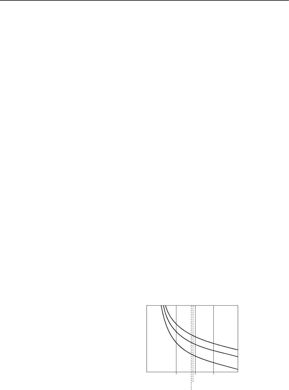
CHAPTER 7 - APPLICATIONS AND PROGRAMMING
138
2) In the chart, at hot in P640, we can find the maximum Thermal
Class that the motor will withstand due to the locked rotor time at hot:
For 6.6 x In @ 12s, we select the closest lower Class: Class 40.
Now it is known that Thermal Class 10 allows one start and Thermal
Class 40 is the upper limit. Thus you must select a Thermal Class
between these two Thermal Classes by considering the number of
start per hour and the time interval between motor On-Off procedures.
The closer to Class 10 you select, more protected will be your motor,
less starts per hour are allowed and longer time intervals between
motor On-Off procedures are required.
The closer to Class 40 you select, nearer the upper motor limit you
will be, thus more starts per hour are allowed and shorter time intervals
between motor On-Off procedures can be used.
To determine the activation times of the hot Thermal Classes, i. and.,
when the motor is running at rated load with current lower than or
equal to 100% of the Nominal Current, use the multiplier factor shown
in Table 6.34 at P640, as a percentage of the current that the motor is
absorbing when running continuously.
For example:
A motor is running with 80% In and then is switched Off.
It is switched On again immediately.
The starting current is 3xIn @ 25s.
The selected Thermal Class, in the table 6.22, is the Class 10 with
33,7s @ 3xIn.
As shown in table 6.33, the correction factor for 80% In is 0.48.
The final activation time will be: 0.48 x 33.7s = 16.2s, i. and., the time
is reduced at cold start from 33.7s to 16.2s at hot start. Thus, a new
motor is not allowed before the thermal motor image decreases, i.and.,
cools down.
When the Service factor (S.F.) is different from 1.00, but its use is
required, you can find in the chart, cold, the points for the S.F. = 1.15
and a table for S.F. = 1.15.
If you want to know the thermal protection activation time for other
Service Factor (S.F.), displace the line xIn proportionally to the left.
7.2.1.3 Time reduction when
changing from cold starting
to hot starting
7.2.1.4 Service Factor
Figure 7.26 – Using the S.F. to find new times
t(s)
0xIn
of the Motor
15
20
25
Cold
F.S.=1.15
F.F.=1.25
2x 3x 4x

139
CHAPTER 8
DIAGNOSTICS AND TROUBLESHOOTING
This Chapter helps the user to identify and correct possible faults that
can occur during the Soft-Starter SSW-06 operation. This Chapter also
provides instructions about periodical inspections and cleaning
requirements.
8.1 FAULTS AND POSSIBLE
CAUSES
FAULT
E03
Undervoltage at
Power Section during
Operation
Phase Loss or
Voltage Unbalance
in the Power Section
during Operation
Phase Loss in the
Power at the Start
E04
Soft-Starter
Overtemperature
E05
Motor Overload
E06
External Fault
E10
Error in the Copy
Function
E15
Motor not connected
E16
Overvoltage
DESCRIPTIONOFTHEACTUATION
When the voltage between phases is lower
than the programmed value during the
programmed time. The motor rated voltage is
used as a reference.
When the voltage between phases is
lower or higher during the programmed
time, or when phase loss has been
detected. The other two motor phases are
used as reference.
When there is no voltage synchronization
pulse at the start.
When the thermostats of the heat sink act.
When the times given by the curves of the
programmed thermal classes exceed the
programmed values.
When the digital input programmed to No
External Fault opens.
When the Keypad (HMI) has been loaded
with parameters of different version as the
switch.
When there is no current synchronism
pulse at the initial start.
When the voltage between phases is
higher than the programmed on during the
programmed time. As reference is used the
rated line voltage.
POSSIBLECAUSES
Power supply is lower than programmed at P400
and P600.
The value programmed at P604 and P605 exceeds
the limits permitted for the application.
Voltage drop during start.
Phase loss in the power supply.
Input transformers have been undersized.
Actuation problems with input contactor.
Fuses at input are open.
Bad contact in the power supply connections.
Wrong motor connection.
Panel with unsuitable cooling. Not permitted Start
cycles.
Not permitted Start cycles.
Thermal classes are programmed lower than
permitted by the motor duty.
Off/On intervals shorter than required for the
motor cooling.
The value of the thermal protection saved when
switching off return when switched on again.
DI4...DI6 wiring is open or not connected to +24V.
X1 connector of the CCS6 control board is
disconnected.
A bid to copy the HMI parameter to the
Soft-Starter with different Software version.
Bad contact of the motor connections.
Thyristors or internal By-pass relays are
short-circuited.
Power supply is higher than programmed at P400,
P602 and P603.
Transformer tap selected with too high voltage.
Capacitive power supply with too low inductive load.
RESET
Power-on
Manual Reset
Auto-reset
DIx
Power-on
Manual Reset
Auto-reset
DIx
Power-on
Manual Reset
Auto-reset
DIx
Power-on
Manual Reset
Auto-reset
DIx
Power-on
Manual Reset
Auto-reset
DIx
Power-on
Manual Reset
DIx
Power-on
Manual Reset
Auto-reset
DIx
When most of the errors are detected, the motor is switched off and the
error is shown on the display as EXY, XY being the error code.
For the SSW-06 Soft-Starter to return to normal operation after an error,
it is necessary to reset it. This can generally be done in the following
ways.
It can be reset as follows:
Disconnecting and reapplyingAC power (power-on reset);
Pressing the of the keypad (HMI) - (manual reset);
Automatic reset through P206 setting (auto-reset);
Via digital input: DI2 (P264 = 2) or DI3 (P265 = 2) or DI4 (P266 = 6)
or DI5 (P267 = 6) or DI6 (P268 = 6).
The table below shows the reset details for each possible cause.
Table 8.1 - Detailed Fault Description

CHAPTER 8 - DIAGNOSTICS AND TROUBLESHOOTING
140
FAULT
E24
Programming Error
E28
Timeout error in the
telegram of the serial
communication
E29
Communication error
Fieldbus inactive
E30
Communication board
error Fieldbus inactive
E31
Keypad (IHM)
Connection Fault
E32
Motor Overtemperature
(DI6 = PTC)
E41
Self-Diagnosis fault
during power-on
E62
Too long time for the
current or torque limit
during the start
E63
Locked Rotor
at the start end
DESCRIPTIONOFTHEACTUATION
When the setting of an incompatible
parameter has been programmed.
When the Soft-Starter does not receive
telegrams from the master during a time
longer than has been programmed at P314.
When the Fieldbus communication board is
active and Communication with the Master is
inactive.
Soft-Starter could not be accessed the
Fieldbus communication board during the
initialization or during the operation.
When the electrical connection between the
Keypad (HMI) and the switch has been
interrupted.
When the DI6 digital input is programmed to
the motor PTC input and the detector acts.
When the conversion of the input current is
out of allowed range: 2,5V ±3%.
When the start time due to start with current
limit, current ramp or torque control is longer
than the time set at P102.
When at the end of the acceleration ramp
the current is not lower than 2x the motor
rated current (P401x2) before closing of the
internal By-pass relay.
POSSIBLECAUSES
Setting attempt of an incompatible parameter.
See Table 4.2.
The Timeout programmed at P314 is longer than the
time programmed between the telegrams sent by
the network master.
The master does not send telegrams cyclically,
program P314=0.
When the serial communication is not used,
program P314=0.
For more information, please refer to the
Soft-Starter SSW-06 serial communication manual.
Communication error between the Fieldbus
Network Master and the Soft-Starter
SSW-06.Master configuration problem.
Communication cables are not installed correctly.
When the Fieldbus communication board is not
being used, program P309=0.
For more details, please refer to the Fieldbus
communication manual of the Soft-Starter SSW-06.
Data exchange problems between the Soft-Starter
SSW-06 and the Fieldbus communication board.
Wrong configuration of the Fieldbus communication
board, programmed at P309.
Board connection problem.
When the Fieldbus communication board is not
being used, program P309=0.
For more details, please refer to the Fieldbus
communication manual of the Soft-Starter SSW-06.
Bad contact in the Keypad (HMI) connection.
Electrical noise (electromagnetic interference).
Excessive load on the shaft.
Load cycle too high (large number of starts and stops
per minute).
Ambient temperature too high.
Bad contact or short-circuit (resistance <100) in the
wiring from motor thermistor to X1 terminal of the
CCS6 board.
P268 is wrong.
Stalled motor, locked motor.
Bad electric contact in the current transformer cables
or control board connection cables.
A thyristor or contactor in short-circuit.
Problems in the control board.
Time programmed at P102 is shorter than required.
The programmed current limit at P110 is too low.
The programmed current limit at any point of
current ramp is too low.
The programmed torque limit at any point of the
torque control is too low.
Stalled motor, locked rotor.
The motor rated current that has been programmed
at P401 is wrong.
The time programmed at P102 is shorter than the
required to start the motor by voltage ramp.
The transformer that supplies the motor may be
saturated and requires too much time to recover
from the starting current.
Stalled motor or locked rotor.
For special motor that support this working
condition you can set P617=0.
RESET
Automatic
Reset after
fault
correction
Automatic
Reset after
fault
correction
Automatic
Reset after
fault
correction
Power-on
Automatic
Reset after
fault
correction
Automatic
Reset after
fault
correction
Power-on
Manual Reset
Auto-reset
DIx
Power-on
Manual Reset
DIx
Power-on
Manual Reset
DIx
Power-on
Manual Reset
DIx
Table 8.1 (Cont.) - Detailed Fault Description

CHAPTER 8 - DIAGNOSTICS AND TROUBLESHOOTING
141
Table 8.1 (Cont.) - Detailed Fault Description
FAULT
E65
Motor Undercurrent at
full voltage operation
E66
Motor Overcurrent at
full voltage operation
E67
Wrong phase
sequence at start
begin
E70
Undervoltage at the
Electronics supply
E71
Internal By-pass relay
contact is open
E72
Overcurrent before
By-pass closing
E74
Current unbalance
E75
Line frequency out of
range
E76
Undercurrent before
By-pass closing
E77
By-pass relay contact
is closed
DESCRIPTIONOFTHEACTUATION
When the current is lower than the
programmed during the programmed time.
Motor rated current is used as reference.
When the current is higher than the
programmed during the programmed time.
The rated motor current is used as
reference.
When the signal interruption sequence of
the synchronism do not follows the
R/1L1, S/3L2, T/5L3 sequence.
When the supply of the control board power
supply is lower than 93,5Vac.
When any problem with the contacts of the
By-pass relay, internal or external, has been
detected at full voltage after start.
When at the end of the acceleration ramp
the current is not lower than 2x the rated
current of the Soft-Starter (P295x2) before
closing of the internal By-pass relay.
When the current of one of the phases is
lower or higher during the programmed time.
The other motor phases are used as
reference.
When the frequency is lower or higher than
the limits from 42,5 to 69Hz during more than
0.5s.
When at the end of the acceleration ramp
the current is lower than 0,1x the rated
current of the Soft-Starter (P295x0,1)
before closing of the internal By-pass relay.
When the contact of the By-pass relay, internal
or external, will not opened.
POSSIBLECAUSES
The percent value programmed as maximum
acceptable undercurrent limit (P610) is lower than
required for the motor and its application.
In applications with hydraulic pumps which ay be
operated without load.
The percent value programmed as maximum
acceptable overcurrent limit (P612) is lower than
required for the motor and its application.
Motor with instantaneous overload.
Stalled motor or locked rotor.
Parameter P620 has been programmed without
need. Wrong phase sequence.
This can be changed in another point of the power
supply line.
Phase loss in the control board supply.
Bad contact in the control board supply.
Fuse in control board supply is open,
glass fuse 5x20mm 2A with delayed action.
Bad contact of the internal or extenal By-pass relay
supply.
Bad contact of the internal or extenal By-pass relay
due to any overload. an overload
P140=1 without external By-pass relay connected.
Rated Soft-Starter current has been wrong
programmed at P295.
The time programmed at P102 is shorter than
required for the motor start by voltage ramp.
Motor rated current is higher than allowed for the
Soft-Starter.
Stalled motor or locked rotor.
Value programmed at P614 and P615 is out of
range and not allowed for this application.
Voltage drop in one or more phases of the power
supply.
Phase loss in the power supply.
Input transformers have been undersized.
Input fuses are open.
Bad contact of the power supply connections or
connections to the motor.
When the Soft-Starter + motor are being supplied
by a generator that is unable to drive the motor at
rated load or is unable to start the motor.
Power supply fault or thyristor fault before Bypass
closing.
The rated Soft-Starter current has been wrong
programmed at P295.
Rated motor current is lower than the minima
current (P295x0.3).
For tests you can set P616=0.
Bad contact of the internal or external By-pass relay
due to any overload. an overload.
Short Circuit in the contact of the internal or external
By-pass relay due to any overload. an overload.
Short Circuit in parallel with the contact of By-pass:
thyristor in short circuit, external short circuit.
RESET
Power-on
Manual Reset
Auto-reset
DIx
Power-on
Manual
ResetAuto-
reset
DIx
Power-on
Manual Reset
DIx
Power-on
Manual Reset
DIx
Power-on
Manual Reset
DIx
Power-on
Manual Reset
DIx
Power-on
Manual Reset
Auto-reset
DIx
Power-on
Manual Reset
DIx
Power-on
Manual Reset
DIx
Power-on
Manual Reset
DIx

CHAPTER 8 - DIAGNOSTICS AND TROUBLESHOOTING
142
NOTES!
Fault Actuation Forms:
E24:
- Indicates the code in the LED display and the fault description in the
LCD display (see table 4.2 )
- Motor can not be started.
- Switches off the relay that has been programmed to "No Error"
- Switches on the relay that has been programmed to "With Error"
E28, E29 and E30:
- Indicates the code in the LED display;
- Indicates the code and the fault description in the LCD display;
- The actuation form can be configured at P313.
E31:
- Soft-Starter proceeds operation normally;
- No Keypad (HMI) commands are accepted;
- Indicates code in the LED display;
- Indicates the Code and the Fault description in the LCD display.
E41:
- Soft-Starter operation is not allowed (motor can not be started);
- Indicates code in the LED display;
- Indicates the Code and the Fault description in the LCD display.
E70:
- The last four faults will not be saved in the memory when the power
supply is switched off (line disconnection) with stopped motor.
OTHERFAULTS:
- Relay is switched off when programmed to "No Error";
- Relay is switched on when programmed to "With Error";
- Motor is switched off, when it is enabled;
- Indicates the fault code in the LED display;
- The LCD display indicates the fault code and the fault description;
- Some data is also saved in the EEPROM memory:
.The number of the occurred fault (the three previous faults are
displaced);
.The status of the thermal protection (motor overload);
.The status of the time of the running/powering hours.
NOTES!
When E04 message is displayed (Soft-Starter overtemperature), wait a
few minutes for it to cool down before it can be reset.
When E05 message is displayed (motor overload) or E30 (motor
overtemperature), wait a fewminutes for it to cool down the motor slightly
before the Soft-Starter can be reset.
CHAPTER 8 - DIAGNOSTICS AND TROUBLESHOOTING
143
8.2 TROUBLESHOOTING
PROBLEM POINT TO BE CORRECTIVE ACTION
CHECKED
Motor does not run Incorrect wiring 1. Check the power and control connections. For example the DIx digital inputs
programmed for Enabling or External Fault must be connected to +24V.
Incorrect programming 1. Check if the parameters are properly programmed for the application;
Fault 1. Check if the Soft-Starter is not disabled due to a Fault condition
(Refer to table 8.1).
Motor does not reach Motor stall 1. Increase the current limit level, if programmed to current limit.
rated speed 2. Increase the torque limit level, if the torque control mode has been selected.
Motor speed varies Loose Connections 1. Disable Soft-Starter, switch OFF the power supply and tighten all connections
(oscillates) 2. Check if all internal connections are tightened.
Motor speed too low Motor Nameplate Data 1. Check if the used motor meets the application requirements.
or too high
Display OFF Keypad (IHM) connection 1.Check the keypad connections to the Soft-Starter
Check the power 1. Rated supply voltage must be following:
board X1.1, X1.2 Umin = 93.5 Vac
and PE Umax= 253 Vac
Blown Fuse 1. Replace the fuse of the control board.
Jerking during Parameter setting 1. Reduce the time set at P104.
pump deceleration of the Soft-Starter
Table 8.2 - Troubleshooting of the most frequent problems
NOTE!
When contacting WEG for service or technical assistance, please have
the following data on hand:
Soft-Starter Model:
Serial number, manufacturing date and hardware revision, as indicated
on the Soft-Starter nameplate (Refer to Section 2.4);
Software Version (Refer to Section 2.2);
Information about the application and Soft-Starter programming.
For further information, training or service please contact the Technical
Assistance or Distributor closest to you.
8.3 CONTACTING WEG:
TELEPHONE / FAX / E-MAIL
CHAPTER 8 - DIAGNOSTICS AND TROUBLESHOOTING
144
8.4 PREVENTIVE
MAINTNANCE
DANGER!
Always disconnect the main power supply before touching anyelectrical
component associated to the SSW-06 Soft-Starter
High voltages can be present even after the power supply has been
disconnected. Wait at least 3 minutes for the complete discharge of
the power capacitors.
Always connect the equipment frame to the protection earth (PE) at
the correct point for this.
ATTENTION!
Electronic boards have components sensitive to electrostatic
discharges.
Never touch the components orconnectors directly. If this is unavoidable,
first touch the metallic frame or use a suitable ground strap.
To avoid operation problems caused byharsh ambient conditions, such
as high temperature, moisture, dirt, vibration or premature aging of the
components, periodic inspections of the Soft-Starters SSW-06 and
installations are recommended. .
Never apply a high voltage test on the Soft-Starter SSW-06!
If this is necessary, contact WEG.
COMPONENT PROBLEMS CORRECTIVEACTIONS
Terminal blocks, connectors Loose screws Tighten them (2)
Loose connectors
Blowers (1)/ Cooling Blowers are dirty Clean them (2)
System Abnormal acoustic noise Replace the blower
Blower is not running
Abnormal vibration
Dust in the air filters Clean or replace them (4)
Printed circuit boards Dust, oil or moisture accumulation Clean them (2)
Smell Replace them
Power module/ Dust, oil or moisture accumulation, etc. Clean them (2)
power connections Connection screws are loose Tighten them (2)
Power resistor Discoloration Replace it
Smell
Table 8.3 - Periodic Inspections after Start-up
Notes:
(1) It is recommended to replace the blowers after each 40,000 hours
of operation;
(2) Check the capacitors everysix months. It is recommended toreplace
them after five years of operation;
(3) When the SSW-06 Soft-Starter is stored for a long period of time, it
is recommended that it be energized for 1 hour, in each interval of 1
year.
(4) Two times per month.
Do not use Megohmmeter for the Thyristor testing.
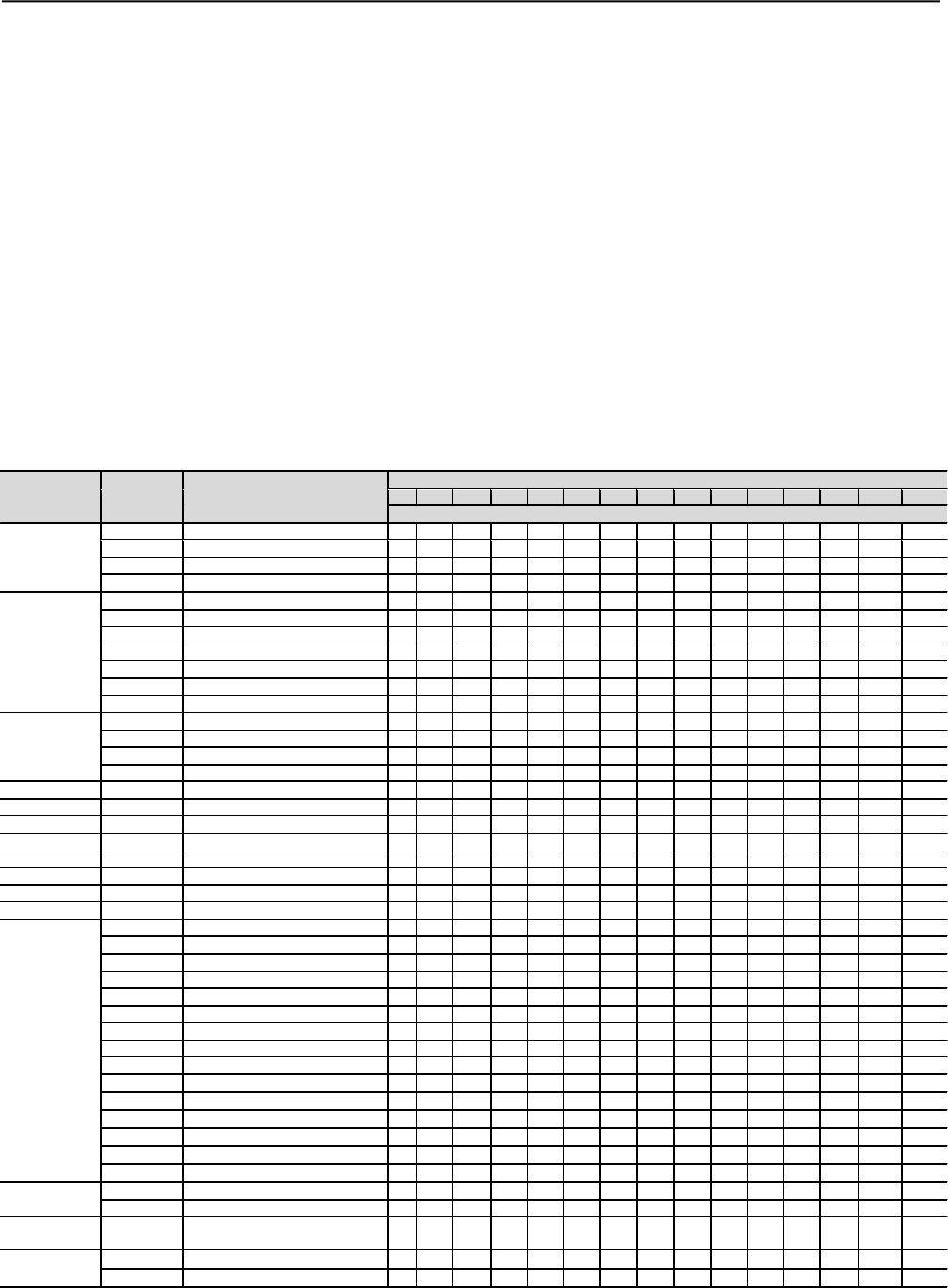
CHAPTER 8 - DIAGNOSTICS AND TROUBLESHOOTING
145
When it is necessary to clean the SSW-06 Soft-Starter, do so
according to the following instructions:
a) Cooling system:
RemoveAC power from the Soft-Starter SSW-06 and wait 3 minutes;
Remove all dust from the ventilation openings by using a plastic
brush or a soft cloth;
Removedust accumulated on the heat sink fins and from theblower
blades with compressed air;
b) Electronic Boards:
RemoveAC power form the Soft-Starter SSW-06 and wait 3 minutes;
Remove all dust from the printed circuit boards by using an anti-
static soft brush or remove it with an ionized compressed air gun
(example Charges Burtes Ion Gun (non nuclear) -
referenceA6030-6DESCO).
If necessary, remove the PCBs from the Soft-Starter SSW-06;
Always use a ground strap.
8.4.1 Cleaning Instructions
8.5 SPARE PART LIST
Name Item
Number Specification
Models (Ampéres) 220-575Vac
85
130
170
205
255
312
365
412
480
604
670
820
950
1100
1400
Units per Soft-Starter
Thyristor
Module
0298.0029
Thyristor Module 142A 1600V
3
0298.0030 Thyristor Module 180A 1600V 3
0303.9560
Thyristor Module
250A 1600V
3
0298.0031
Thyristor Module
285A 1600V
3
Disc
Thryristor 0298.0032 Disc Thyristor 490 1600V 6 6
0298.0033
Disc
Thyristor
551A 1600V
6
0298.0079 Disc Thyristor 750A 1600V 6
0298.0080
Disc
Thyristor
900A 1600V
6
0303.9595
Disc
Thyristor
1200A 1600V
6
6
6
0303.7150 Disc Thyristor 1800A 1600V 6 6
0303.7215
Disc
Thyristor
2400
A 1600V
6
Fan
0400.3673
Fan
120x120mm 110V/220V
2
2
2
2
2
2
3
3
0400.3500
Fan
225x225mm 110V
2
0400.3519
Fan
225x225mm 115V
2
0400.3403
Fan
280x280mm 220V
2
2
Fuse-Control 0305.6198 Glass Fuse 2A 250V 1 1 1 1 1 1 1 1 1 1 1 1 1 1 1
Keypad (
HMI
)
417114250
Man
-
Machine Interface
1
1
1
1
1
1
1
1
1
1
1
1
1
1
1
CCS6
4160.1765
Control Card
1
1
1
1
1
1
1
1
1
1
1
1
1
1
1
CPS63-00 4160.1767 Source and Power Card 1 1 1 1 1 1 1
CPS63
-
01
41
60.1822
Source and Power Card
1
1
1
CPS64 4160.1804 Source and Power Card 1 1 1 1 1
RCS60
4160.1768
RC Snuber
Card
1
1
1
1
RCS61
4160.1793
RC Snuber
Card
1
1
1
1
1
1
1
1
Current
Transformer
0307.3020
TC 425/1,4A
-
2,8VA
–
2.5%
3
0307.3021
TC 650/1,24A
-
4,3VA
–
2.5%
3
0307.3022
TC 850/1,24A
-
4,7VA
–
2.5%
3
0307.3023
TC 1025/1,24A
-
6,8VA
–
2.5%
3
0307.3024 TC 1275/1,24A-7,5VA –2.5% 3
0307.3025
TC
1560/1,24A
-
9,1VA
–
2.5%
3
0307.3026 TC 1825/1,24A-10VA –2.5% 3
0307.3066
TC 2060/2A
-
8VA
–
2.5%
3
0307.3067
TC 2
400/
2A
-
10
VA
–
2.5%
3
0307.3068 TC 3020/2A-12VA –2.5% 3
0307.3069 TC 3350/2A-13VA –2.5% 3
0307.3070
TC
4100
/2A
-
12V
A
–
2.5%
3
6434.2307
TC
4750/
2A
-
27
VA
–
2.5%
3
6434.2408
TC
5500
/2A
-
36
VA
–
2.5%
3
6434.2418
TC
7000
/2A
-
46
VA
–
2.5%
3
By
-
pass
Relay
0304.
1197
Rel
ay
Latching 100A
–
48Vcc
3
0304.1198
Rel
ay
Latching 200A
–
48Vcc
2
2
3
3
3
3
By-pass
Contactor
035511610 Contactor CWM105DP-SB955 3 3 3 3 3
RC Snnuber 0301.1631 Wire Resistor 25R 50W 10% 3 3 3
0302.4490 Polip. Capacitor 0,47
F 850V 3 3 3
Table 8.4 - Spare Parts List
* a) The 110Vca fan is used in the SSW06XXXXT2257XSH1Z-PL
b) The 220Vca fan is used in the SSW06XXXXT2257XSH2Z
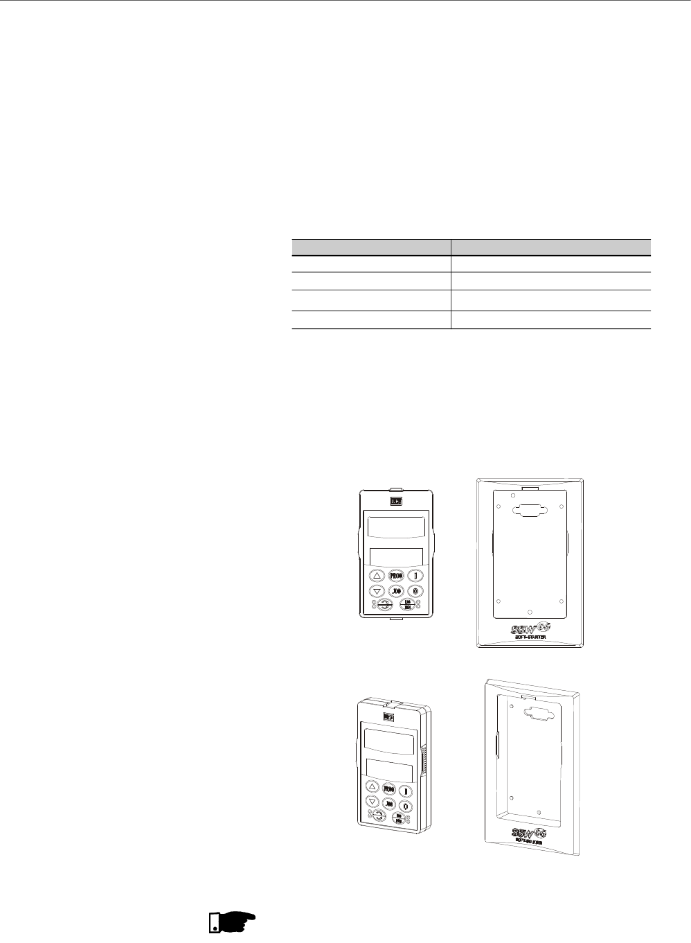
146
CHAPTER 9
9.1 REMOTE KEYPAD (HMI)
AND CABLES
OPTIONS AND ACCESSORIES
This chapter describes the options and accessories that can be used
with the Soft-Starter SSW-06. These options and accessories are:
The MMI can be assembled either from the Soft-Starter or remotely. If
using the remote MMI, the frame KMR-SSW-06 (frame for remote
mounting) can be used. The advantage of using the frame is the
appearance (esthetic) of the remote MMI. The maximum cable length
is 5m (16.40 ft). To acquire cables from WEG, see the following models.
Cable Length WEG Part No
1m (3.28ft) 0307.6890
2m (6.56ft) 0307.6881
3m (9.84ft) 0307.6873
5m (16.40ft) 0307.6865
Table 9.1 - Connection cables CAB-HMI SSW-06-X
The keypad cable must be installed separately from the power cables,
following the same recommendations as for the CCS6 control board
(Refer to Section 3.2.8).
For assembling, see details in figure 9.2 and 9.3.
Figure 9.1 - HMI and remote HMI frame for panel installation
NOTE!
Due to voltage drop in the Keypad cable, do not use cables longer
than 5m (16.40ft).
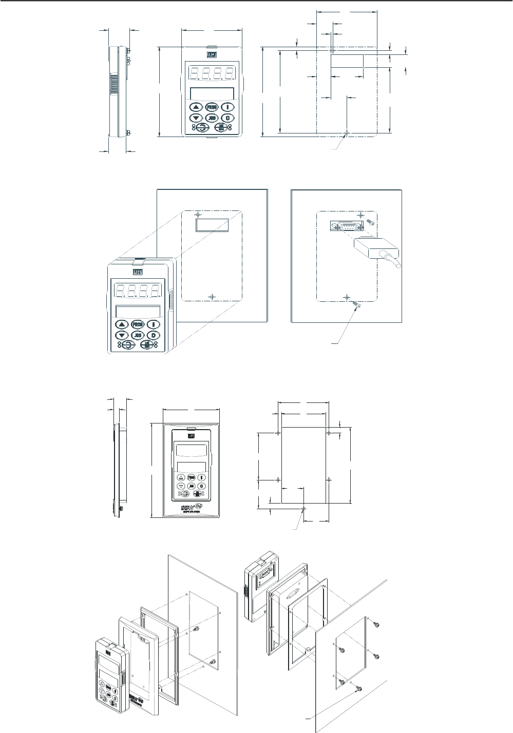
CHAPTER 9 - OPTIONS AND ACCESSORIES
147
Figure 9.3 - Dimensions in mm (in) and how to install the Keypad in the panel and frame
Figure 9.2 - Dimensions in mm (in) and how to install the Keypad directly in the panel
17.5
(0.69)
65
(2.56)
17.4
(0.69)
4.9
(0.39)
16
(0.63)
82.2
(3.24)
34.9
(1.37)
15.1
(0.59)
2.4
(0.09)
103
(4.06)
5
(0.20)
113
(4.45)
4 (2x)
(0.16)
Screw M3x8 (2x)
Torque 5.5Nm
Front View Back View
84 (3.31)
5.5
(0.22)
42
(1.65)
120
(4.72)
36.5
(1.44)
91
(0.36)
74
(2.31)
4.5 (5x)
(0.18)
Screw M3x8 (2x)
Torque 5.5Nm
b) Dimension of frame with Keypad
Back View
73 (2.87)
45
(1.77)
8.1
(0.32)
22.7
(0.89)
65
(2.56)
113
(4.45)
18.8
(0.74)
a) Keypad (HMI) Dimensions
21.5 (0.85) 94
(3.70)
149
(5.87)
Front View
10 (0.39)
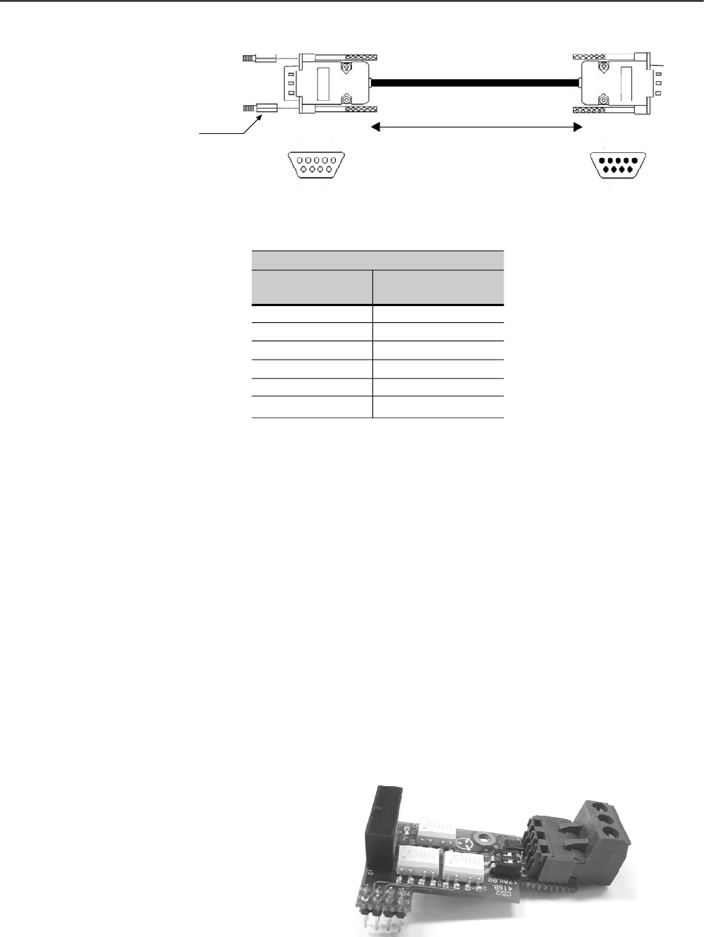
148
CHAPTER 9 - OPTIONS AND ACCESSORIES
Figure 9.4 - Cable for remote keypad connectiion
Table 9.2 – Coonection pins (DB9) for cables
5m (16.40ft) (the frame may be or not used)
Connection Pins
Keypad (HMI) side
1
2
3
4
8
9=SHIELD
Cable Connection
Connection Pins
Soft-Starter side
1
2
3
4
8
9= SHIELD
When the interface RS-485 is used, the master can controlseveral
drives connected to the same bus. The protocol Modbus-RTU
allows the connection of up to 247 slaves (1 slave per address),
provided repeaters are also used along the bus. This interface
ensures good noise immunity, allowing maximum cable length of
up to 1000 m.
There are two ways to make available the interface RS-485 in the
Soft-Starter SSW-06:
WEG Item: 417114255.
Converter RS-232 to RS-485 with galvanic isolation.
Connected inside the product (on the connector XC8 of the control
board CCS6).
For more details, please refer to the Serial Communication of the
Soft-starter SSW-06.
9.2 RS-485 for the Soft-Starter
SSW-06
9.2.1 RS-485 Communication Kit
for SSW-06 (KRS-485)
Figure 9.5 – Optional board RS-485 for the SSW-06
HMI
Soft-Starter
DB9 connector - Male
Max. recommended cable length: 5m(16.40ft)
DB9 connector - Female
HMISoft-Starter
Insert spacer to connect
thecable to the Soft-Starter 15
96
51
69
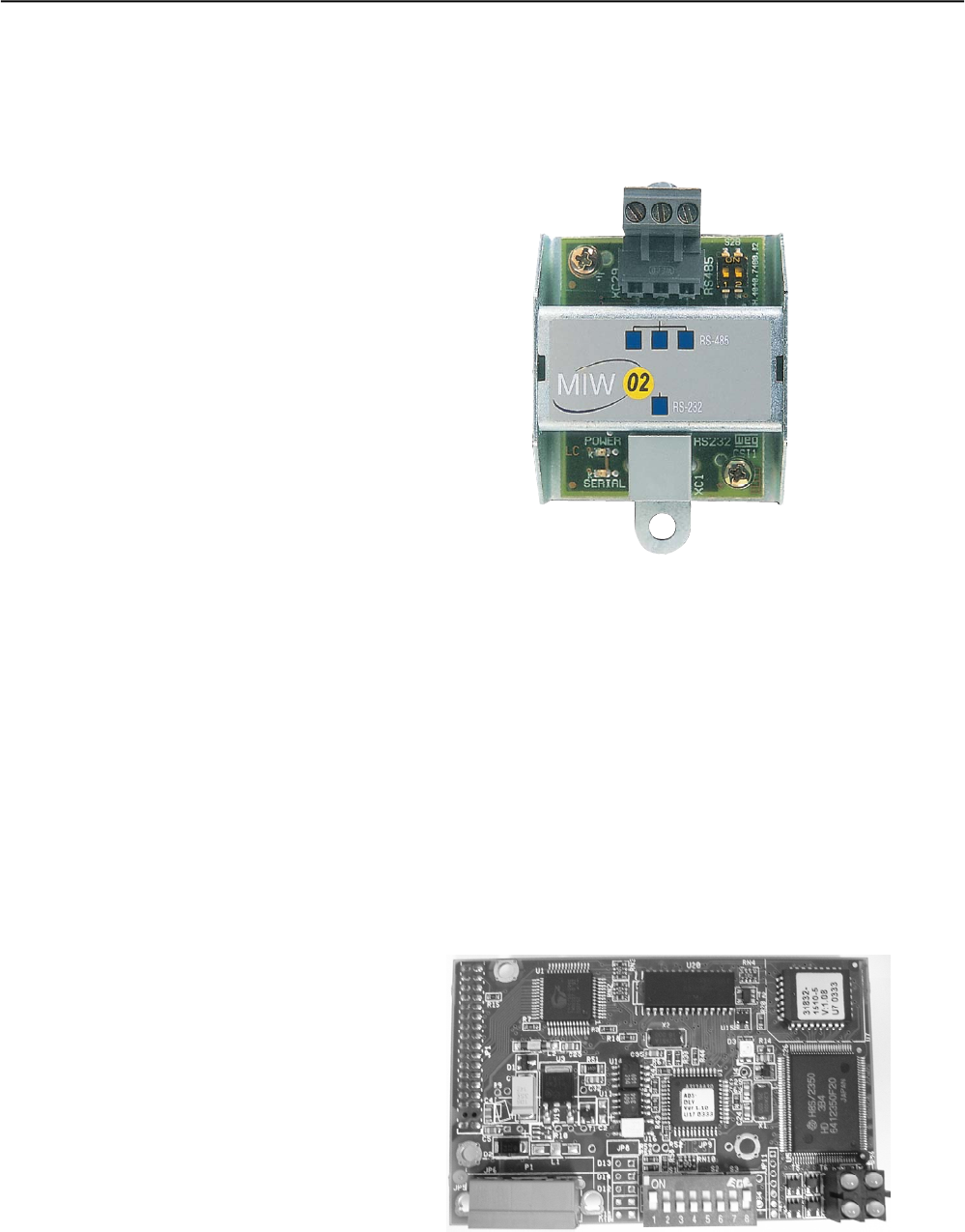
CHAPTER 9 - OPTIONS AND ACCESSORIES
149
WEG Item: 417100543.
Converter RS-232 to RS-485 with galvanic isolation.
Module outside the product, connected to the interface RS-232 of
the SSW-06.
For more details, please refer to the MIW-02 Manual.
9.2.2 Optional Module MIW-02
Figure 9.6 – Optional module MIW-02
To enable the Soft-Starter SSW-06 for the Profibus DP or DeviceNet
communication, the use of a communication board required. This
communication board is available as optional kit.
Two protocols are available for the Soft-Starter SSW-06:
WEG Item: 417114253.
The communication protocol DeviceNet has been developed with
the purpose to provide a fast, cyclic and deterministic
communication between the masters and slaves.
For more details, please refer to the Fieldbus Communication
Manual.
9.3 FIELDBUS
COMMUNICATION KITS
9.3.1 Fieldbus DeviceNet
Communication
Kit for SSW-06 (KFB-DN)
Figure 9.7 – Board of the optional DeviceNet Kit
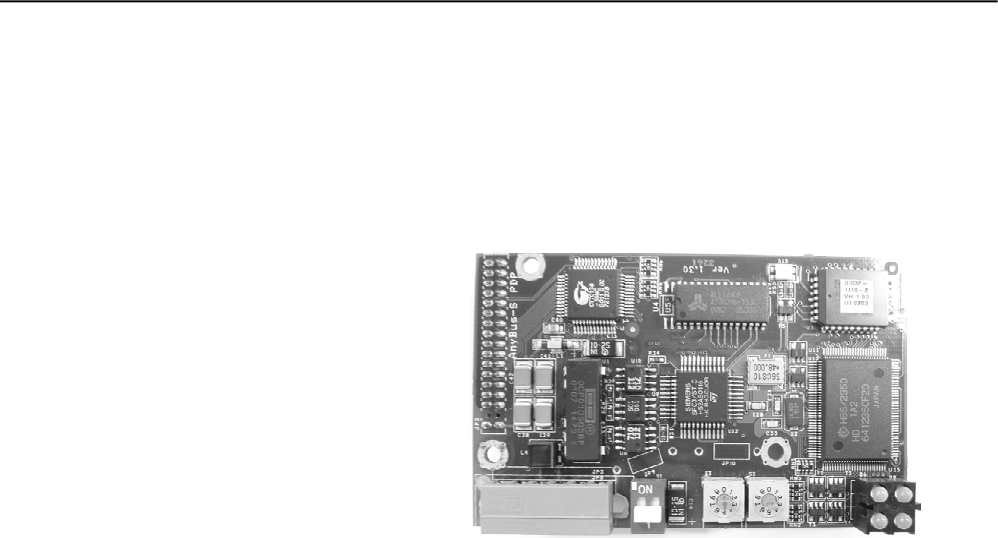
150
CHAPTER 9 - OPTIONS AND ACCESSORIES
WEG Item: 417114252.
TheProfibusDP communication protocolis used for interconnecting
controllers and industrial equipment, such as sensors, valves,
drives, bar code readers, frequencyinverters, panels and operation
interfaces.
For more details, please refer to the Fieldbus Communication
Manual.
9.3.2 Fieldbus Profibus DP
communication kit for
SSW-06 (KFB-PD)
Figure 9.8 – Board of the optional Profibus DP kit

151
CHAPTER 10
TECHNICAL SPECIFICATIONS
This Chapter describes the technical specifications (electrical and
mechanical) of the Soft-Starters SSW-06.
10.1 CURRENTSAND RATINGS ACCORDING TO UL508
Table 10.1 - Powers and currents for standard connection with three cables according to UL508 (Room temperature of 55ºC)
SSW-06 Model
SSW-06.0085
SSW-06.0130
SSW-06.0170
SSW-06.0205
SSW-06.255
SSW-06.0312
SSW-06.0365
SSW-06.0412
SSW-06.0480
SSW-06.0604
SSW-06.0670
SSW-06.0820
SSW-06.0950(1)
SSW-06.1100(1)
SSW-06.1400(1)
Rated
Current
3xIn @ 30s
A
85
130
170
205
255
312
365
412
480
604
670
820
950
1100
1400
Rated
Current
4.5xIn @ 30s
A
57
87
113
137
170
208
243
275
320
403
447
547
633
733
933
220/230V
hp kW
30 22
50 37
60 45
75 55
100 75
125 90
150 110
150 112
200 150
250 185
250 185
300 225
350 260
450 330
500 370
380/400V
hp kW
50 37
75 55
100 75
100 75
150 110
175 130
200 150
250 185
300 225
350 260
400 300
500 370
600 450
700 525
900 670
440/460V
hp kW
60 45
100 75
125 90
150 110
200 150
250 185
300 220
350 260
400 300
500 370
550 410
600 450
700 525
800 600
1050 775
575V
hp kW
75 55
125 90
150 110
200 150
250 185
300 220
350 260
450 330
500 370
600 450
650 485
750 550
850 630
1000 750
1350 1000
55ºC 55ºC
SSW-06 Model
SSW-06.0085
SSW-06.0130
SSW-06.0170
SSW-06.0205
SSW-06.0255
SSW-06.0312
SSW-06.0365
SSW-06.0412
SSW-06.0480
SSW-06.0604
SSW-06.0670
SSW-06.0820
SSW-06.0950(1)
SSW-06.1100(1)
SSW-06.1400(1)
Rated
Current
3xIn @ 25s
A
147
225
294
355
441
540
631
713
831
1046
1160
1420
1645
1905
2424
Rated
Current
4.5xIn @ 25s
A
98
150
196
236
294
360
421
475
554
697
773
947
1096
1270
1616
220/230V
hp kW
50 37
75 55
100 75
125 90
150 110
200 150
250 185
250 185
350 260
450 330
450 330
550 410
650 485
800 600
1000 750
380/400V
hp kW
75 55
125 90
150 110
200 150
250 185
300 220
350 260
450 330
550 410
700 525
850 630
1000 750
1150 820
1350 1000
1750 1290
440/460V
hp kW
100 75
150 110
200 150
250 185
350 260
450 330
500 370
550 410
650 485
800 600
900 670
1150 820
1350 1000
1600 1175
200 1475
575V
hp kW
150 110
200 150
300 220
350 260
450 330
550 410
650 475
750 550
850 630
1100 800
1200 900
1500 1200
1750 1290
2000 1475
2500 1850
55ºC 55ºC
Table 10.2 – Powers and currents for connection inside the motor delta with six cables according to UL508
(Room Temperature of 55ºC)
(1) Power valid for room temperature of 40ºC.
(1) Power valid for room temperature of 40ºC.
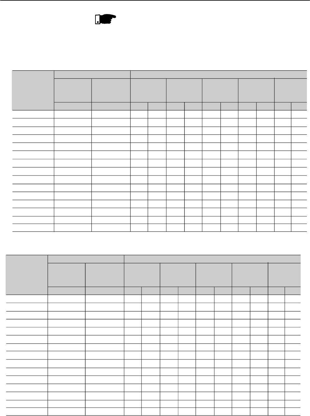
CHAPTER 10 - TECHNICAL SPECIFICATIONS
152
NOTE!
Maximum ratings indicated in tables 10.1 and 10.3 are based on 3 x
SSW-06 Soft-Starter Rated Current during 30s and 10 starts per hour
(3xInSSW@30s).
SSW-06 Model
SSW-06.0085
SSW-06.0130
SSW-06.0170
SSW-06.0205
SSW-06.0255
SSW-06.0312
SSW-06.0365
SSW-06.0412
SSW-06.0480
SSW-06.0604
SSW-06.0670
SSW-06.0820
SSW-06.0950(1)
SSW-06.1100(1)
SSW-06.1400(1)
Rated
Current
3xIn @ 30s
A
85
130
170
205
255
312
365
412
480
604
670
820
950
1100
1400
Rated
Current
4.5xIn @ 30s
A
57
87
113
137
170
208
243
275
320
403
447
547
633
733
933
220/230V
hp kW
30 22
50 37
60 45
75 55
100 75
125 90
150 110
150 110
200 150
250 185
250 185
350 260
400 300
450 330
550 410
380/400V
hp kW
60 45
75 55
125 90
150 110
175 132
200 150
250 185
300 220
350 260
450 330
500 370
550 410
750 550
800 600
1000 750
440/460V
hp kW
60 45
100 75
125 90
150 110
200 150
250 185
300 225
350 260
400 300
500 370
550 410
700 525
800 600
900 670
1200 900
525V
hp kW
75 55
125 90
150 110
200 150
250 185
300 220
350 260
440 315
500 370
600 450
650 485
800 600
900 670
1100 810
1400 1050
55ºC 55ºC
Table 10.3 - Powers and currents for standard connection with three cables according to WEG motors
575V
hp kW
75 55
125 90
150 110
200 150
250 185
300 225
350 260
450 330
500 370
650 485
750 550
850 630
1050 775
1200 900
1500 1100
10.2 CURRENTSAND RATINGS FOR IP55, IV POLE WEG MOTOR
(1) Power valid for room temperature of 40ºC.
SSW-06 Model
SSW-06.0085
SSW-06.0130
SSW-06.0170
SSW-06.0205
SSW-06.0255
SSW-06.0312
SSW-06.0365
SSW-06.0412
SSW-06.0480
SSW-06.0604
SSW-06.0670
SSW-06.0820
SSW-06.0950(1)
SSW-06.1100(1)
SSW-06.1400(1)
Rated
Current
3xIn @ 25s
A
147
225
294
355
441
540
631
713
831
1046
1160
1420
1645
1905
2424
Rated
Current
4.5xIn @ 25s
A
98
150
196
236
294
360
421
475
554
697
773
947
1096
1270
1616
220/230V
hp kW
60 45
75 55
125 90
150 110
175 130
200 150
250 185
250 185
350 260
450 330
500 370
600 450
700 520
800 600
1050 775
380/400V
hp kW
100 75
150 110
200 150
250 185
300 220
350 260
450 330
500 370
600 450
750 550
850 630
1000 750
1200 900
1400 1030
1750 1290
440/460V
hp kW
125 90
175 132
200 150
300 220
350 260
450 330
500 370
600 450
700 525
850 630
950 700
1200 900
1400 1030
1600 1175
2000 1475
525V
hp kW
125 90
200 150
250 185
300 220
400 300
500 370
600 450
700 525
800 600
1050 775
1150 820
1400 1050
1650 1200
1900 1400
2450 1800
55ºC 55ºC
575V
hp kW
150 110
250 185
300 220
350 260
450 330
550 410
650 485
800 600
900 670
1150 820
1250 920
1550 1140
1800 1325
2100 1550
2650 1950
Table 10.4 - Powers and currents for connection inside the motor delta with six cables according to WEG motors
(Room Temperature of 55ºC)
(1) Power valid for room temperature of 40ºC.

CHAPTER 10 - TECHNICAL SPECIFICATIONS
153
10.3 POWER DATA
Supply
Capacity
Thyristors (SCRs)
Power voltage AC input (R/1L1, S/3L2, T/5L3)
Frequency
Maximum number of starts per hour
Starting Cycle
220V to 575 Vac: (-15% to +10%), or (187 to 632) Vac
50 to 60Hz (± 10 %), or (45 to 66) Hz
10 (1 every 6 minutes) Models 85A to 820A.
5 (1 every 12 minutes) Models 950A to 1400A.
3 x In during 30 s
Maximum reverse peak voltage 1600V
III (UL 508/EN 61010)
Overvoltage Category
NOTE!
Maximum ratings indicated on the tables 10.2 and 10.4 are based on
3 x SSW-06 Soft-Starter Rated Current during 25s and 10 starters per
hour (3xInSSW@ 25s).
10.4 ELECTRONICS/PROGRAMMING DATA
110 to 230 Vac (-15% to +10%), or (94 to 253)Vac
50 to 60Hz (± 10 %), or (45 to 66)Hz
280mA Maximum
Voltage Ramp;
Current Limit;
Pump Control;
Torque Control;
Torque Control;
5 isolated digital inputs;
Minimum high level: 18Vdc;
Maximum low level: 3Vdc;
Maximum Voltage: 30Vdc;
Input Current: 11mA @ 24Vdc;
Programmable functions.
1 input for motor thermistor;
Actuation: 3k9Release: 1k6;
Minimum resistance: 100;
PTCB referenced to the DGND through 249resistor.
1 analog output, not isolated, (0 to +10)V, RL 10k(maximum load);
Resolution: 11bits;
Programmable functions.
1 analog output, not isolated,(0 to 20)mA/(4 to 20)mA, RL=500/1%@10V;
Resolution: 11bits;
Programmable functions.
2 relays with NO-contacts, 240Vac, 1A, programmable functions.
1 relay with NO/NC-contact, 240Vac, 1A, programmable functions.
Supply Control Voltage
Connector X1A (1,2)
Frequency
Consumption
Control Method
Inputs Digitals
Motor Thermistor
Input
Outputs Analogs
Relay

CHAPTER 10 - TECHNICAL SPECIFICATIONS
154
10.4 ELECTRONICS/PROGRAMMING DATA(cont.)
Overcurrent;
Undercurrent;
Overvoltage;
Undervoltage;
Phase loss;
Reversed phase sequence;
Overtemperature of heat sink;
Motor overload;
External fault;
Open By-pass contact (when Soft-Starter is fitted with internal By-pass);
Overcurrent before By-pass (when Soft-Starter is fitted with internal By-pass);
CPU Error;
Keypad (HMI) communication error.
Programming error;
8 keys: enable / disable, Increment, Decrement, Direction of Rotation, Jog, Local/
Remote and Programming;
LCD-Display, 2 lines x 16 columns and 7 segments
4 digits LED display
Led’s for indication of the direction of rotation and indication on the Mode of
Operation (LOCAL/REMOTE)
Permits access/changing of all parameter;
External mounting is possible, cables up to 5m (16.40ft) are available.
Safety Protections
Keypad (HMI) HMI-SSW06

CHAPTER 10 - TECHNICAL SPECIFICATIONS
155
10.5 MECHANICAL DATA
Figure 10.1 - 85A and 130A Models
29.5
85.5
(3.37) 41.4
(1.09)
15.8
(0.41)
21
(0.55)
51.4
(1.35)
17.3
(0.45)
193.3
(7.61)
5.3 (2x)
Top View X
59.5
(2.34)
44.5
(1.75)
(1.16)
(0.14)
18
(0.47)
R 4.7 (4x)
(0.12)
37.5
(0.98)
5.3 (2x)
(0.14)
22.5(4x)
(0.88)
168.3
(6.63)
Under View Y
Air Outlet
224
(9.61)
132 (5.20)
75
(2.95)
28.5
(1.12)
11.5
(0.45)
350
(13.78)
370
(14.57)
X
Air Inlet
Y
52.5
(2.07)
288.5
(11.36)
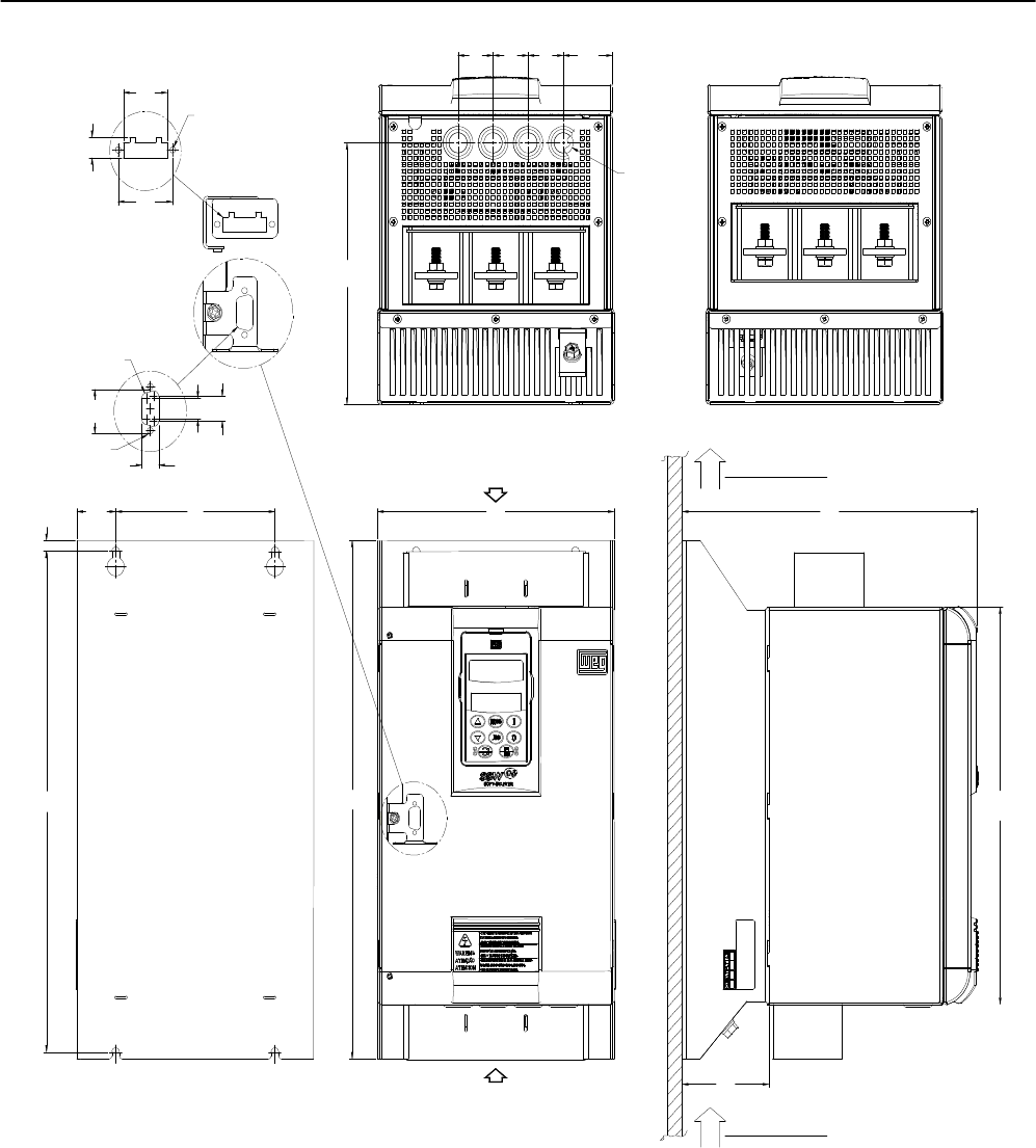
CHAPTER 10 - TECHNICAL SPECIFICATIONS
156
Figure 10.2 - 170A to 205A Models
17.3
(0.45)
33
(1.30)
R 4.7 (4x)
(0.12)
5.3 (2x)
Top View X
41.4
(1.09)
(0.14)
22.5(4x)
(0.88)
37.5
(0.98)
Under View Y
51.4
(1.35)
33
(1.30) 33
(1.30) 46.4
(1.83)
221.9
(8.74)
5.3 (2x)
(0.14)
18
(0.47)
21
(0.55)
15.8
(0.41)
9.1
(0.36)
36.5
(1.44)
150
(5.91)
425
(16.73)
440
(17.32)
Air Inlet
Y81.5
(3.21)
337.2
(13.28)
223 (8.78)
Air Outlet
278
(10.9)
X
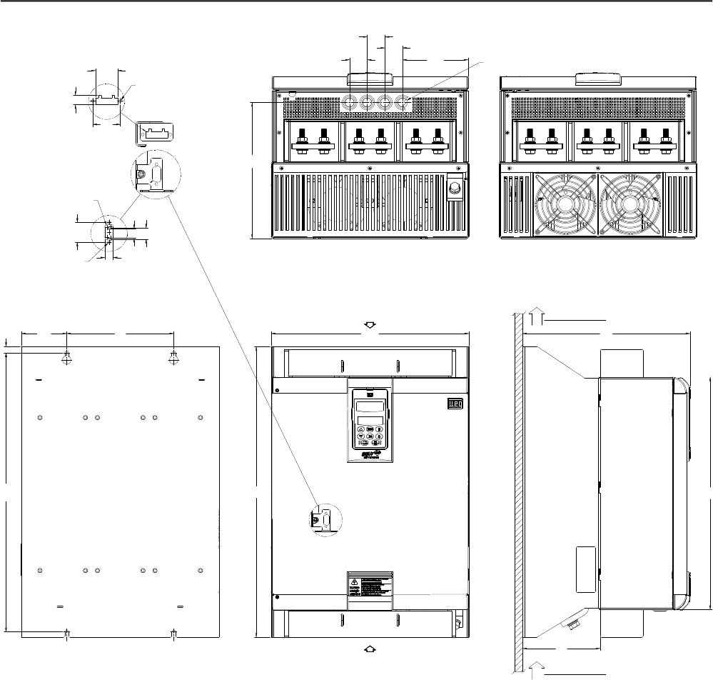
CHAPTER 10 - TECHNICAL SPECIFICATIONS
157
Figure 10.3 - 255A, 312A and 365A Models.
17.3
(0.45)
R 4.7 (4x)
(0.12)
5.3 (2x)
Top View X
41.4
(1.09) 22.5(4x)
37.5
(0.98)
Under View Y
51.4
(1.35)
5.3 (2x)
(0.14)
18
(0.47)
21
(0.55)
15.8
(0.41)
12.5
(0.49)
84.8
(3.34) 200
(7.87)
527
(20.78)
550
(21.65)
Air Inlet
Y
145
(5.771)
440
(13.28)
369.5 (14.55)
Air Outlet
278 (10.94)
X
(0.14)
(0.88)
33
(1.30)
33
(1.30) 33
(1.30) 122.5
(4.82)
257
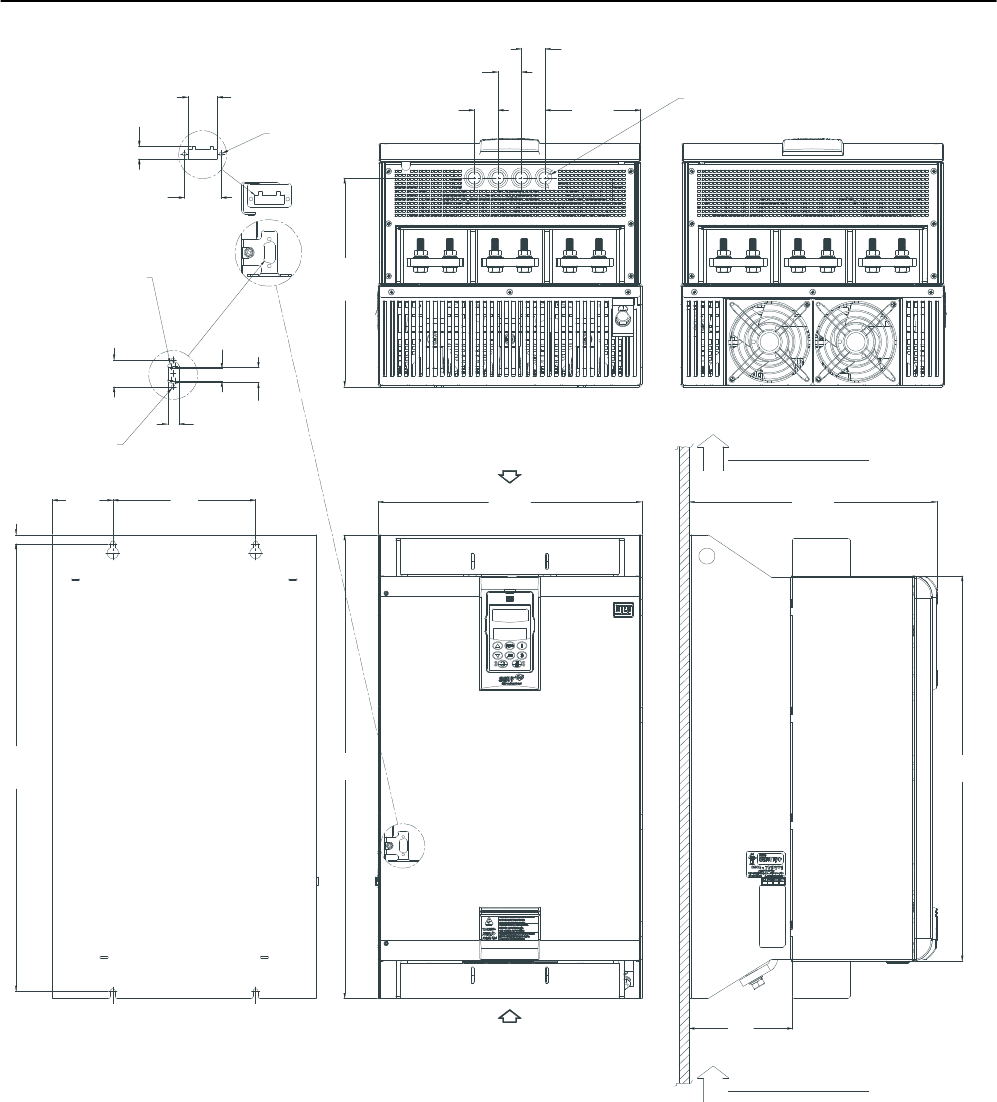
CHAPTER 10 - TECHNICAL SPECIFICATIONS
158
Figura 10.4 - Models de 412A, 480A and 604A
17.3
(0.45)
R 4.7 (4x)
(0.12)
5.3 (2x)
(0.14)
Top View X
41.4
(1.09) 22.5(4x)
37.5
(0.98)
Under View Y
51.4
(1.35)
5.3 (2x)
(0.14)
18
(0.47)
21
(0.55)
15.8
(0.41)
12.5
(0.49)
84.8
(3.34) 200
(7.87)
627.5
(24.70)
650
(25.59)
Air Inlet
Y
347.3
(13.67)
540
(21.26)
Air Outlet
X
33
(1.30)
33
(1.30)
33
(1.30)
133.8
(5.27)
392.5
(11.52)
145
(5.71)
540
(21.26)
(0.88)
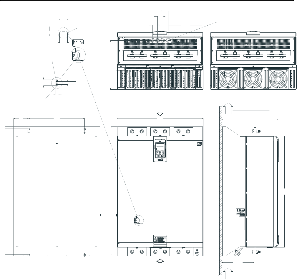
CHAPTER 10 - TECHNICAL SPECIFICATIONS
159
Figura 10.5 - 670A and 820A Models
17.3
(0.45)
R 4.7 (4x)
(0.12)
5.3 (2x)
(0.14)
Top View X
41.4
(1.09) 22.5(4x)
37.5
(0.98)
Under View Y
51.4
(1.35)
5.3 (2x)
(0.14)
18
(0.47)
21
(0.55)
15.8
(0.41)
12.5
(0.49)
95
(3.74)
350
(13.78)
775
(30.51)
795
(31.30)
Y
357.3
(14.07)
540
(21.26)
Air Outlet
X
33
(1.30)
33
(1.30)
33
(1.30)
218.6
(8.61)
302.4
(11.91)
204.3
(8.04)
685
(31.30)
(0.88)
Air Inlet
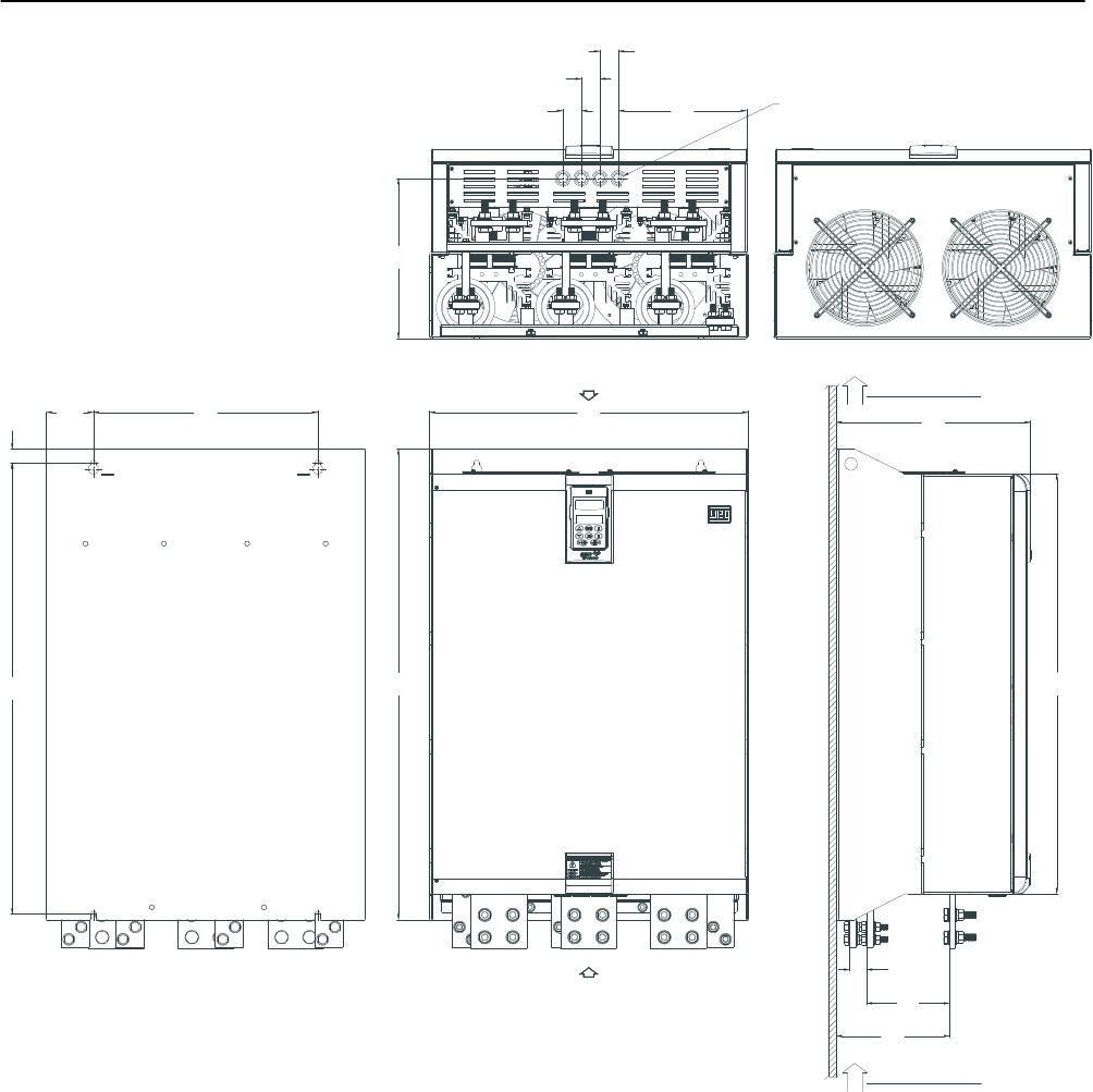
CHAPTER 10 - TECHNICAL SPECIFICATIONS
160
Figura 10.6 - 950A Models
Top View X
22.5(4x)
Under View Y
25
(0.98)
84.1
(3.31) 400
(15.75)
810
(31.89)
845
(33.27)
Y
347.3(13.65)
568
(22.37)
Air Outlet
X
33
(1.30)
33
(1.30)
33
(1.30)
229
(9.00)
288
(11.33)
202
(7.96)
754
(29.68)
(0.88)
Air Inlet
148
(5.83)
30
(1.18)
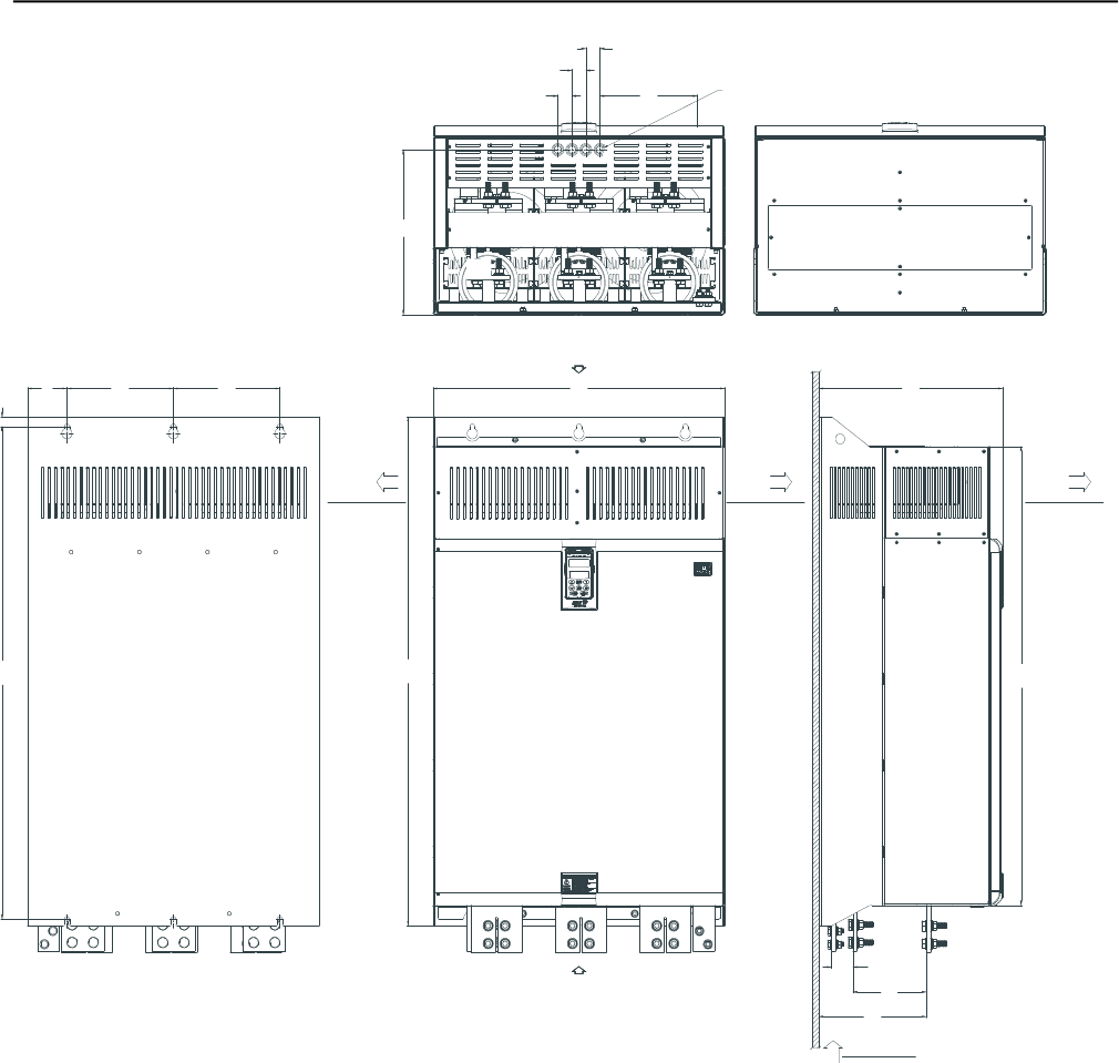
CHAPTER 10 - TECHNICAL SPECIFICATIONS
161
Figura 10.7 - 1100A and 1400A Models
Y
Top View X
22.5(4x)
Under View Y
22
(0.87)
93
(3.64)
250
(9.84)
1110
(43.70)
1147
(45.16)
432
(17.01)
685 (26.97)
Air
Outlet
X
33
(1.30)
33
(1.30)
33
(1.30)
229
(9.00)
288
(11.33)
252 (9.91)
1034
(40.70)
(0.88)
Air Inlet
172 (6.78)
50
(1.97)
Air
Outlet
Air
Outlet
250
(9.84)
Y
