12625 3 Taco 0013 Vdtf3 Instructions Print User Manual
12571 3 Taco 0010-Vdtf3 Instructions 12571_3_Taco 0010-VDTF3 Instructions 12571_3_Taco 0010-VDTF3 Instructions pdf pumpproducts
12606 3 Taco 0012-Vdtf4 Instructions 12606_3_Taco 0012-VDTF4 Instructions 12606_3_Taco 0012-VDTF4 Instructions pdf pumpproducts
User Manual: Pump 12625 3 Taco 0013-Vdtf3 Instructions
Open the PDF directly: View PDF ![]() .
.
Page Count: 8
The Variable Speed Delta T 00®Cartridge Circulator (00-VDT) is a microprocessor-based pump which automatically adjusts its perfor-
mance to deliver the optimal heat transfer based on the actual operation of the system. The 00-VDT regulates the temperature to provide
a fixed temperature difference (ΔT) of between 5 - 50°F between two field installed sensors.
Variable Speed Differential Temperature Control
Variable speed pumping to maintain a set differential temperature (delta T or ΔT) between two sensors allows for automatic adjustment of
the pump’s performance to match the load of the system or zone, eliminate velocity noise in zone valve systems and conserve energy.
Since delta T is directly related to flow rate, the pump’s speed continually adjusts to the required BTU per hour. In almost all applications
the design of the system was based on being able to maintain a certain delta T and figured by using the universal hydronics equation of
BTU/hr = GPM x 500 x ΔT. Given that, any time there is a change to the heat load (i.e. warmer day or greater heat loss from a structure)
then the GPM should change to match the required BTU/hr. This is achieved when the variable speed 00-VDT Circulators automatically
and continually adjust their GPM output (by varying speed) to match the required BTU/hr output of the system, no matter the changes
in heat load, while always maintaining the designed delta T between a supply and return sensor.
Applications
Instruction Sheet
00®Variable Speed Delta T (00-VDT)
102-359
SUPERSEDES: May 1, 2010 EFFECTIVE: October 1, 2010
Plant ID# 001-3927
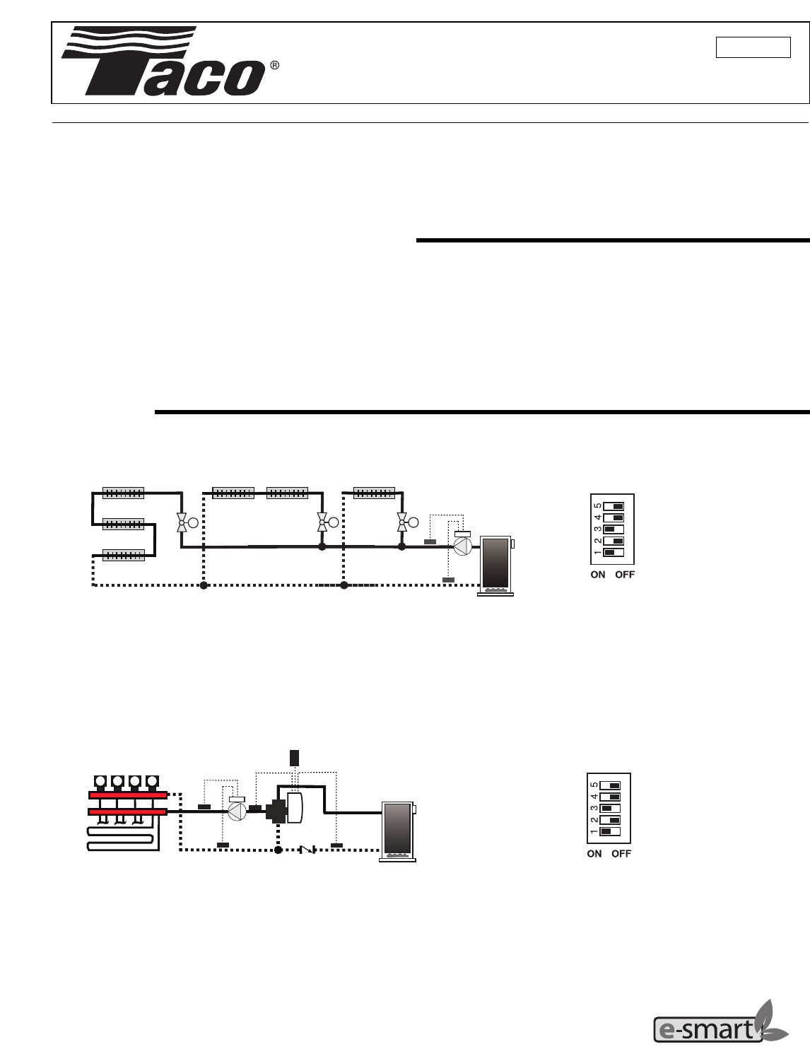
DIP 5 = Off
DIP 4 = Off
DIP 3 = On
DIP 2 = Off or On
DIP 1 = On
Delta T Across a Series Loop System Using Zone Valves
"00"-VDT
Supply
Sensor
M
M
Return
Sensor
M
The 00-VDT Variable Speed Circulator adjusts its speed to maintain the differential temperature (based on the RANGE dial setting) between the
supply sensor and the return sensor whenever a heat demand is present. This will increase overall comfort and sharply reduce boiler short-cycling.
The 00-VDT will also control velocity noise issues in the system, eliminatin
g
the need for a pressure differential bypass valve.
DIP 5 = Off
DIP 4 = Off
DIP 3 = On
DIP 2 = Off or On
DIP 1 = On
Delta T Across Multi-Zone Radiant Manifolds with Loop Actuators
iSeries-R
B
C
A
B
C
A
“00”-VDT
Supply
Sensor Return
Sensor
M M M M
Outdoor
Sensor
Boiler
Sensor
The 00-VDT Variable Speed Circulator adjusts its speed to maintain the differential temperature (based on the RANGE dial setting) between the
supply sensor and the return sensor whenever a heat demand is present. The 00-VDT will also eliminate velocity noise by slowing the actual flow
rate through the zone to the minimum required to deliver proper heat. If other zones on the manifold open, the 00-VDT will increase its speed to
deliver the required BTU’s, while at the same time maintaining the designed for delta T across the radiant system.
See www.taco-hvac.com for additional applications for the 00-VDT circulators.
A Taco resource – saving product
Minimum Variable Speed Output
When the 00-VDT is configured for reverse acting mode (ΔT operation), a minimum variable
speed ouput is incorporated during operation to insure proper flow across both sensors. In
this case, the variable speed output is adjusted between the selected minimum variable
speed output percentage and full output. Depending on the amount of system resistance
in your application, select the preferred minimum variable speed output from the table to
the right. The 00-VDT also provides full output for 30 seconds when the Heat Request
appears, then resumes normal operation.
Note: Minimum variable speed output is not available when configured for Direct Acting Mode (DIP switch 3 set to Off).
Pump Start-up
When the 00-VDT is powered up, the circulator operates at full speed for 30 seconds before varying its speed anywhere between min-
imum and full speed as required to maintain the selected differential temperature.
In Direct Acting Mode (DIP switch 3 = Off) the speed of the circulator will ramp up as required to maintain the selected differential
temperature.
Exercising
Every 72 hours of no operation, the 00-VDT is designed to exercise for 10 seconds in order to prevent precipitate build-up in the pump.
The % OUT LED turns on during the exercising function.
Sequence of Operation
Power Up and Heat Request
Whenever the 00-VDT is powered up, the green PWR LED turns on. The 00-VDT starts operating once a heat request signal is present
at the Heat Request (Ht Req) terminals. The heat request terminals come factory jumpered so the pump will start as soon as it is pow-
ered up. The jumper may be removed and a heat request signal may be provided by external end switches from zone valves or Taco
ZVC/SR series zone controls, applying a dry contact closure or a powered 24 V (ac) signal across the Ht Req terminals. Once a heat
request signal is present, the green HEAT REQ LED turns on.
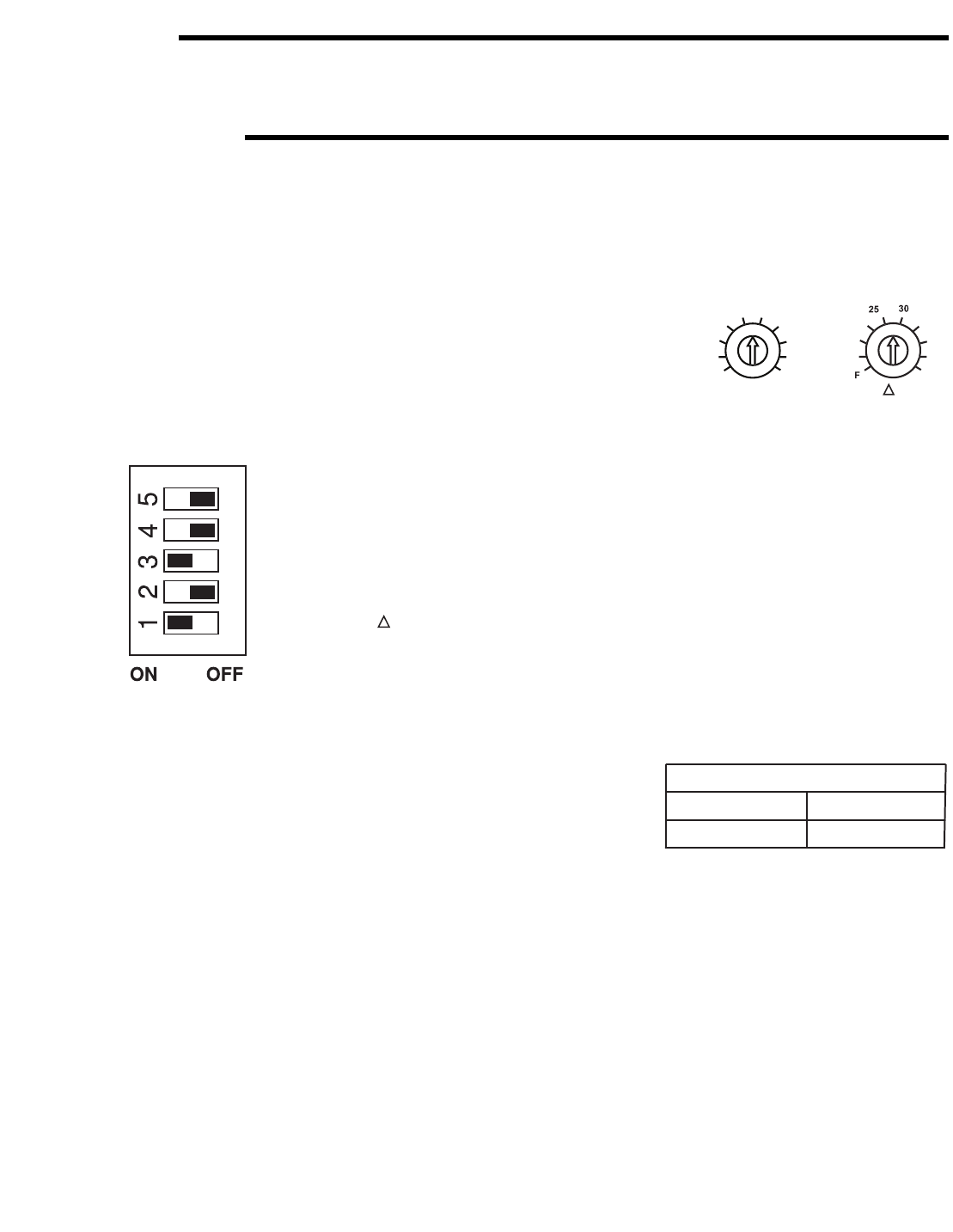
Delta T Setting and Operation
Once a heat request is present, the 00-VDT operates to provide a fixed ΔT between the supply
sensor (S2) and the return sensor (S1). The fixed ΔT is set using the RANGE dial, where 5°F and
50°F corresponds to 1 and 10 respectively on the RANGE dial, with the temperature increasing
in 5°F increments. The percent output (% OUT) LED flashes at different rates based on the speed
of the pump.
Dip Switch Settings
2
1
2
3
8
4
5
6
7
9
1
0
RANGE
5
º
1
0
º
F
1
5
º
F
4
0
º
F
2
0
º
F
º
F
º
F
35
º
F
4
5
º
F
50
º
F
T
DIP Switch 1: T Operation = On
DIP Switch 2: Minimum Speed = Off or On
DIP Switch 3: Mode of Operation = On
DIP Switch 4: Output Response = Off
DIP Switch 5: Output Characteristic = Off or On
DIP switch 2 = Off DIP switch 2 = On
Minimum Variable Speed Output
Normal (default) Lower
Pump Selection
The circulator should be sized, using conventional sizing practices, based on the required head and flow for the system or zone on
which the circulator is being installed.
3
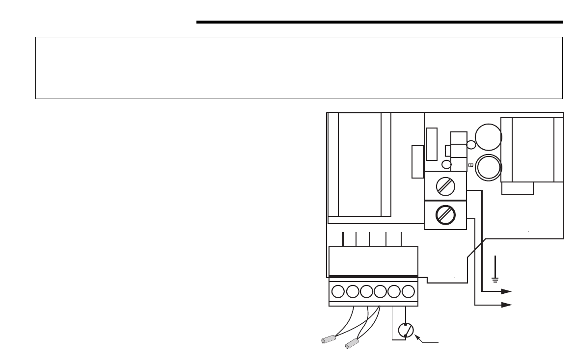
Wiring and Sensor Installation
Powering the Control
Insert the line voltage wires through the knockout of the enclosure
and connect the live wire to the H terminal and the neutral wire to
the N terminal on the PC Board. Ensure that no power is present
during this process.
Heat Request
The heat request signal may be provided by the factory installed
jumper or the jumper can be removed and a heat request signal
may be provided by external end switches from zone valves or
Taco ZVC/SR series zone controls, applying a dry contact closure
or a powered 24 V (ac) signal across the Ht Req terminals.
Sensors
Do not apply power to these terminals as this will damage the PC
Board. The wiring terminals for the sensors may be removed for
ease of installation.
Do not run the wires parallel to telephone or power cables. If the
sensor wires are located in an area with strong sources of electro-
magnetic interference (EMI), shielded cable or twisted pair should
be used or the wires can be run in a grounded metal conduit. If
using shielded cable, the shield wire should be connected to the
Com terminal on the PC Board and not to earth ground.
Sensor Installation and Placement
The sensors can be strapped directly to the pipe using a cable tie. Insulation should be placed around the sensor to reduce the effect
of air currents on the sensor measurement. The sensors should be placed downstream of a pump or after an elbow or similar fitting.
This is especially important if large diameter pipes are used because the thermal stratifcation within the pipe can result in erroneous
sensor readings. Proper sensor location requires that the fluid is thoroughly mixed within the pipe before it reaches the sensor.
If the system sensor is used to measure duct (air) temperature, the sensor should be mounted in such a manner that it measures the
average duct outlet temperature.
Return Sensor (S1)
Connect the two wires from the return sensor (S1) directly into the Com and S1 terminals on the PC Board.
Supply Sensor (S2)
Connect the two wires from the supply sensor (S2) directly into the Com and S2 terminals on the PC Board.
WARNING: Wiring connections must be made in accordance with all applicable electrical codes.
CAUTION: To prevent electrical shock, disconnect electric power to system at main fuse or circuit
breaker box until installation is complete. When a service switch is installed, more than one discon-
nect switch may be required to deenergize this device for servicing.
S3
N
H
S2 S1 Com
Power: 120 V ±10%
900 VA 60 Hz
Var. Speed: 120 V
(ac) 2.4 A 1/6 hp
Ht
Req
Ht
Req
Made in
Canada
MOV
T2.
5A
2
50V
co
i
l
f
use
0.1µF
R
Y
XFMR
Factory Installed Jumper
or
End Switch
Supply
Sensor (S2)
Return
Sensor (S1)
N
120 V (ac)
H
To ground screw
on PCB enclosure
0.1µF
4
Troubleshooting
As in any troubleshooting procedure, it is important to isolate a problem as much as possible before proceeding. The error messages
greatly simplify troubleshooting of the 00-VDT. When the 00-VDT flashes an error message, identify the fault and follow standard test-
ing procedures to confirm the problem. If you suspect a wiring fault, return to the wiring section on this brochure and carefully check
all external wiring and wiring connections.
For your safety and protection from permanent damage to the microprocessor, the 00-VDT includes a 2.5 A (250 VAC) field replace-
able fuse.
Multi-Status LED
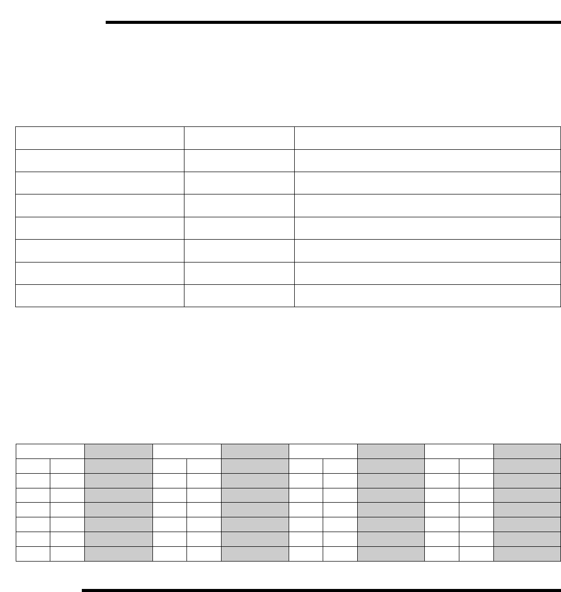
Testing the Sensors
A good quality test meter capable of measuring up to 5,000 kΩ(1 kΩ= 1000Ω) is required to measure the sensor resistance. In addi-
tion to this, the actual temperature must be measured with a good quality digital thermometer.
First measure the temperature using the thermometer and then measure the resistance of the sensor at the 00-VDT. The wires from the
sensor must not be connected to the PC Board while this test is performed. The wiring terminals are easily removed by pulling them
from the PC Board. Using the chart below, estimate the temperature measured by the sensor. The sensor and thermometer readings
should be close. If the test meter reads a very high resistance, there may be a broken wire, a poor wiring connection or a defective sen-
sor. If the resistance is very low, the wiring may be shorted, there may be moisture in the sensor or the sensor may be defective. To test
for a defective sensor, measure the resistance directly at the sensor location.
Temperature Resistance Temperature Resistance Temperature Resistance Temperature Resistance
°F °C Ω°F °C Ω°F °C Ω°F °C Ω
-30 -34 234,196 30 -1 34,558 90 32 7,334 150 66 2,045
-20 -29 165,180 40 4 26,099 100 38 5,828 160 71 1,689
-10 -23 118,018 50 10 19,900 110 43 4,665 170 77 1,403
0 -18 85,362 60 16 15,311 120 49 3,760 180 82 1,172
10 -12 62,465 70 21 11,883 130 54 3,050 190 88 983
20 -7 46,218 80 27 9,299 140 60 2,490 200 93 829
LED LED StatusOO-VDT Status
PWR Solid Power On
HEAT REQ Solid Heat Request
% OUT Flash (Solid) Variable Speed Output
HEAT REQ Flash System Sensor S1 Fault.
00-VDT does not operate.
RED OUT Flash System Sensor S2 Fault.
00-VDT does not operate.
HEAT REQ and RED OUT Flash Boiler Sensor S3 Fault. No sensor should be connected to
S3. 00-VDT does not provide boiler protection.
POWER, HEAT REQ and RED OUT Flash No sensors connected, or incompatible mode and sensor
combination.
Application
1. Maximum operating pressure: 125 psi (862 kPa) on all “00” Series Circulators.
2. Maximum water temperature not to exceed nameplate rating.
3. Cast iron circulators are to be used for closed loop systems. Bronze circulators are to be used for open loop, fresh water, or
potable water systems.
4. Taco Cartridge circulator pumps are for indoor use only – employer uniquement a l´interieur.
5
Replacing Cartridge Assembly
1. Disconnect the electrical supply.
2. Reduce system pressure to 0 psi and allow system to return to room temperature. Isolate the circulator by closing the service valves
or draining the system.
3. Remove the body bolts and swing motor assembly away from the body.
4. Pull cartridge out of the motor housing.
5. Install replacement cartridge, making sure that the cover plate is between the cartridge flange and motor.
6. Make sure the replacement cartridge corresponds to the full circulator product number. A complete parts list is available from your
local plumbing supply wholesaler.
7. Reassemble the circulator using the new gasket and bolts supplied.
8. Follow the “Installation” procedure to start up the circulator.
Installation
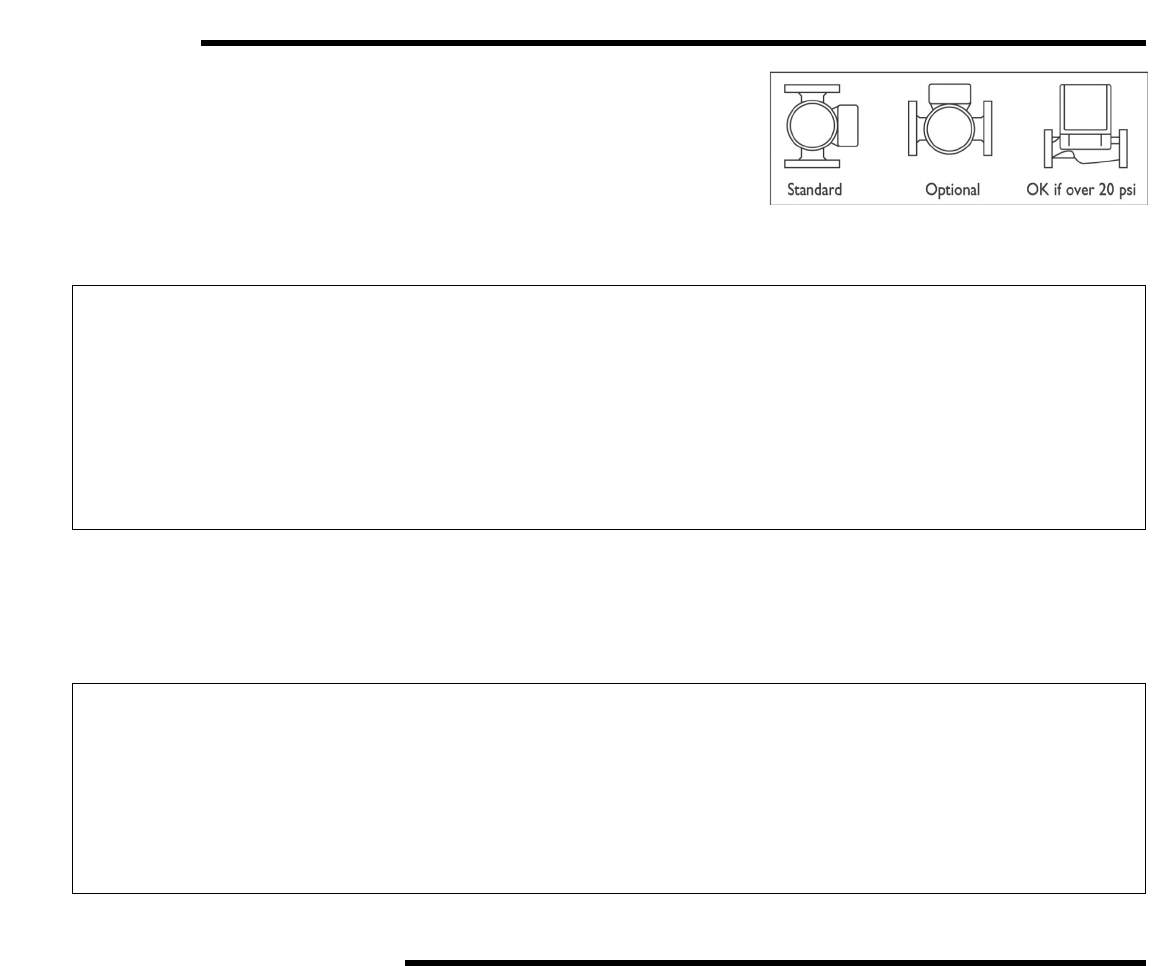
1. Mounting position – Circulator must be mounted with the motor in a horizontal
position. It may be mounted vertically with the motor up, provided that the sys-
tem pressure is at least 20 psi (138 kPa).
2. Rotating body – Body has an arrow on the front that indicates direction of flow. To
rotate body, remove the four body bolts, rotate body and replace bolts. Make sure
that the junction box is NOT located underneath the circulator. (The junction box
must NOT be located in the 6 o’clock position, as viewed from the motor end.)
3. Electrical connections – Observe all applicable codes when connecting to power
supply. The motor is impedance protected, and does not require overload protection. The pump cannot run backwards.
WARNING: Do not use in swimming pool or spa areas; pump has not been investigated for this
application.
WARNING: In the event the retaining screws have been pulled out of the housing, DO NOT replace
them. Use of any other screw may short out the stator windings, creating a risk of
electrical shock.
CAUTION: When installing electrical connections, do not apply mechanical loads to the capacitor
box; otherwise, retaining screws may be pulled out of the housing, making circulator
unusable.
CAUTION: The addition of petroleum based fluids or certain chemical additives to systems
utilizing TACO equipment voids the warranty.
CAUTION: Use supply wires suitable for 90°C – ATTENTION: Employer des fils d´alimentation
adequats pour 90°C.
WARNING: To avoid electrical shock, disconnect the power supply to the circulator and the main
electrical unit.
4. Fill system with tap water – The system must be filled before operating the circulator. The bearings are water lubricated and should
not be allowed to operate dry. Filling the system will result in immediate lubrication of the bearings. It is always good practice to
flush a new system of foreign matter before starting the circulator.
5. Circulator operation – Operate the circulator for 5 minutes immediately after filling system to purge remaining air from the bearing
chamber. This is especially important when installing the circulator during the off-season.

6
Notes
Replacing Integral Flow Check (IFC) Assembly (if applicable)
1. Disconnect the electrical supply.
2. Reduce system pressure to 0 psi and allow system to return to room temperature. Isolate the circulator by closing the service valves
or draining the system.
3. Loosen flange bolts and remove entire circulator from the system to access the flange mounted IFC.
4. Remove IFC, using needle nose pliers.
5. Install replacement IFC by pressing valve into casing until it is firmly seated.
6. Follow the “Installation” procedure to start up the circulator.
Replacing Circuit Board
1. Disconnect the electrical supply and all field wiring to the circuit board.
2. Unplug the 3-pin plastic connector that connects the motor to the circuit board.
3. Bend the lip of the capacitor base to ease the removal of the circuit board. Pull the circuit board up and out.
4. Reverse directions to install the new circuit board.

7
Notes

8
COMFORT MADE EASY.®
TACO, INC., 1160 Cranston Street, Cranston, RI 02920 Telephone: (401) 942-8000 FAX: (401) 942-2360.
TACO (Canada), Ltd., 8450 Lawson Road, Unit #3, Milton, Ontario L9T 0J8. Telephone: (905) 564-9422. FAX: (905) 564-9436.
Visit our web site at: http://www.taco-hvac.com
Copyright 2010 TACO, Inc.
Portions Copyright 2003
tekmar Control Systems, Ltd.
tekmar Control Systems, Inc.
Printed in USA
Notes
LIMITED WARRANTY STATEMENT
Taco, Inc. will repair or replace without charge
(at the company’s option) any Taco 00 Series
circulator or circulator part which is proven
defective under normal use within three (3) years
from the date of manufacture.
In order to obtain service under this warranty, it
is the responsibility of the purchaser to promptly
notify the local Taco stocking distributor or Taco
in writing and promptly deliver the subject product
or part, delivery prepaid, to the stocking distrib-
utor. For assistance on warranty returns, the
purchaser may either contact the local Taco
stocking distributor or Taco. If the subject prod-
uct or part contains no defect as covered in this
warranty, the purchaser will be billed for parts
and labor charges in effect at time of factory
examination and repair.
Any Taco product or part not installed or operated
in conformity with Taco instructions or which
has been subject to misuse, misapplication, the
addition of petroleum-based fluids or certain
chemical additives to the systems, or other
abuse, will not be covered by this warranty.
If in doubt as to whether a particular substance
is suitable for use with a Taco product or part, or
for any application restrictions, consult the
applicable Taco instruction sheets or contact
Taco at (401-942-8000).
Taco reserves the right to provide replacement
products and parts which are substantially similar
in design and functionally equivalent to the
defective product or part. Taco reserves the right
to make changes in details of design, construc-
tion, or arrangement of materials of its products
without notification.
TACO OFFERS THIS WARRANTY IN LIEU OF
ALL OTHER EXPRESS WARRANTIES. ANY
WARRANTY IMPLIED BY LAW INCLUDING
WARRANTIES OF MERCHANTABILITY OR
FITNESS IS IN EFFECT ONLY FOR THE DURA-
TION OF THE EXPRESS WARRANTY SET
FORTH IN THE FIRST PARAGRAPH ABOVE.
THE ABOVE WARRANTIES ARE IN LIEU OF
ALL OTHER WARRANTIES, EXPRESS OR
STATUTORY, OR ANY OTHER WARRANTY
OBLIGATION ON THE PART OF TACO.
TACO WILL NOT BE LIABLE FOR ANY SPE-
CIAL, INCIDENTAL, INDIRECT OR CONSE-
QUENTIAL DAMAGES RESULTING FROM THE
USE OF ITS PRODUCTS OR ANY INCIDENTAL
COSTS OF REMOVING OR REPLACING
DEFECTIVE PRODUCTS.
This warranty gives the purchaser specific
rights, and the purchaser may have other rights
which vary from state to state. Some states do
not allow limitations on how long an implied
warranty lasts or on the exclusion of incidental
or consequential damages, so these limitations
or exclusions may not apply to you.
