134302 2 Pentair Pentek Electronics Manual User
542854 3 Pentair Pentek Electronics Manual 542854_3_Pentair Pentek Electronics Manual
User Manual: Pump 134302 2 Pentair Pentek Electronics Manual
Open the PDF directly: View PDF ![]() .
.
Page Count: 110 [warning: Documents this large are best viewed by clicking the View PDF Link!]
pentek®
ElEctroNics MaNual
inStallatiOn • OPeratiOn • MaintenanCe
WWW.pUMpS.COM

© 2013 PN793 (08/20/13)
Table of Contents
SECTION 1: General Safety Guidelines
SECTION 2: Nomenclature
2.1 Motors
2.2 Drives
2.3 Submersible Motor Controls
SECTION 3: Installation and Setup
3.1 General Installation Guidelines
3.2 Proper Grounding
3.3 Corrosive Water and Ground
3.4 Check Valves
3.5 Start-Up
SECTION 4: Electrical Power
4.1 Mixing Wire Size with Existing Installation
4.2 Wire Splicing
4.3 3-Phase Starters
4.4 Checking Motor Rotation
4.5 3-Phase Current Balancing
4.6 Transformer Sizing
4.7 Using a Generator
4.8 Special Applications
SECTION 5: XE Series 4” SubmersibleMotors
5.1 Motor Inspection
5.2 Testing
5.3 Storage and Transportation
5.4 4” Motor Specifications
5.5 4” Motor Dimensions
5.6 4” Motor Fuse Sizing
5.7 Cable Lengths
5.8 4” Motor Overload Protection
5.9 Motor Cooling
5.10 Starting Frequency
SECTION 6: Pentek® 6” Submersible Motors
6.1 Motor Inspection
6.2 Testing
6.3 Storage and Drain/Fill Instructions
6.4 Motor Specifications
6.5 Motor Dimensions
6.6 Motor Fuse Sizing and Cable Selection
6.7 Overload Protection
6.8 Motor Cooling
6.9 Head Loss In Casing
6.10 Starting Frequency
6.11 Troubleshooting
SECTION 7: Hitachi® 6” Submersible Motors
7.1 Motor Inspection
7.2 Testing
7.3 Storage and Drain/Fill Instructions
7.4 Motor Specifications
7.5 Motor Dimensions
7.6 Motor Fuse Sizing and Cable Selection
7.7 Overload Protection
7.8 Motor Cooling
7.9 Head Loss In Casing
7.10 Starting Frequency
7.11 Troubleshooting
SECTION 8: Pentek Intellidrive™ Variable
Frequency Drives
8.1 General Safety
8.2 Description
8.3 Installation
8.4
Initial Startup ProgrammingProcedure
8.5 Advanced Programming
8.6 I/O Connections
8.7 Wiring Sizing, Repair Parts, Specifications
8.8 Troubleshooting
8.9 Warranty
SECTION 9: PPC Series 50/60 Hz Variable
Frequency Drives
9.1 Pentek PPC-Series Drives
9.2 PPC3 Series Specifications
9.3 PPC5 Series Specifications
9.4 Wiring Connections
9.5 Transducer Connection
9.6 Pentek Assistant
9.7 Timer Function
9.8 Helpful Hints
9.9 PPC3 and PPC5 Tank Sizing
9.10 Reactors And Filters
SECTION 10: PPX NEMA Pump Panels
10.1 Description
SECTION 11: Submersible Motor Controls
11.1 How it Works
11.2 Specifications
11.3 Mounting and Installation
11.4
Wiring Connections and Replacement Parts
SECTION 12: Motor Protective Devices - 50/60 Hz
12.1 How They Work
12.2 Specifications
12.3 Mounting And Installation
12.4 Wiring Connections
SECTION 13: Troubleshooting
13.1 Pump And Motor Problem Analysis
13.2 Motor Troubleshooting Flow Charts
13.3 Testing Submersible Motor Insulation and Winding
Resistance
13.4
Smart Pump Protector Troubleshooting
13.5 Submersible Controls Troubleshooting
SECTION 14: Appendix
14.1 Installation Checklist
14.2 Choosing A Pump System
14.3
Sizing Submersible Pump, Motor, and Tanks
14.4
How to Select the Correct Pumping Equipment
14.5 Sizing Tanks
14.6 Record of Installation
Hitachi® is a registered trademark of Hitachi Industrial Equipment Systems Co., Ltd.
All other brand or product names are trademarks or registered trademarks of Pentair Ltd.
2
SECTION 1: General Safety Guidelines
Important Safety Instructions
SAVE THESE INSTRUCTIONS - This manual contains
important instructions that should be followed during
installation, operation, and maintenance of the product.
Always refer to the equipment owner’s manual for safety
information relevant to that product.
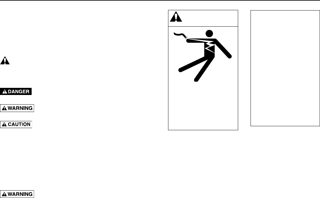
This is the safety alert symbol. When you see this
symbol on your product or in this manual, look for one of
the following signal words and be alert to the potential for
personal injury!
indicates a hazard which, if not avoided, will
result in death or serious injury.
indicates a hazard which, if not avoided,
could result in death or serious injury.
indicates a hazard which, if not avoided,
could result in minor or moderate injury.
NOTICE addresses practices not related to personal
injury.
Carefully read and follow all safety instructions in this
manual and on product.
Keep safety labels in good condition.
Replace missing or damaged safety labels.
Fatal Electrical Shock Hazard.
• Groundmotor,controls,allmetalpipeand
accessories connected to the motor, to the power
supply ground terminal. Ground wire must be at least
as large as motor supply cables.
• Disconnectpowerbeforeworkingonthesystem.
• Donotusethemotorinaswimmingarea.
All work
must be done
by a trained
and qualified
installer
or service
technician.
WARNING
Hazardous voltage. Can
shock, burn, or cause death.
Ground pump before
connecting to power supply.
Disconnect power before
working on pump, motor
ortank.
3
SECTION 2: Nomenclature
2.1 Motors
Table 2-1: Motor Nomenclature
Nomenclature
P 43 B 0 0 1 0 A 2 -01
Brand
P = PENTEK
Motor Size
42 = 4 inch, 2-wire
43 = 4 inch, 3-wire
Motor Material
B = All stainless steel
S = CBM
Horsepower
0005 = 1/2 HP
0007 = 3/4 HP
0010 = 1 HP
0015 = 1-1/2 HP
0020 = 2 HP
0030 = 3 HP
0050 = 5 HP
0075 = 7-1/2 HP
0100 = 10 HP
Frequency
A = 60 Hz.
B = 50 Hz.
C = 50/60 Hz.
Voltage
1 = 115 V, 1 Ph.
2 = 230 V, 1 Ph.
3 = 230 V, 3 Ph.
4 = 460 V, 3 Ph.
5 = 575 V, 3 Ph.
8 = 200 V, 3 Ph
Revision Code
Sample:
P43B0010A2-01 is a PENTEK 4” Stainless Steel Motor
1 HP, 60 Hz., 230 V, 1 Ph., Rev. 1
Name Plate Example:
4
SECTION 2: Nomenclature
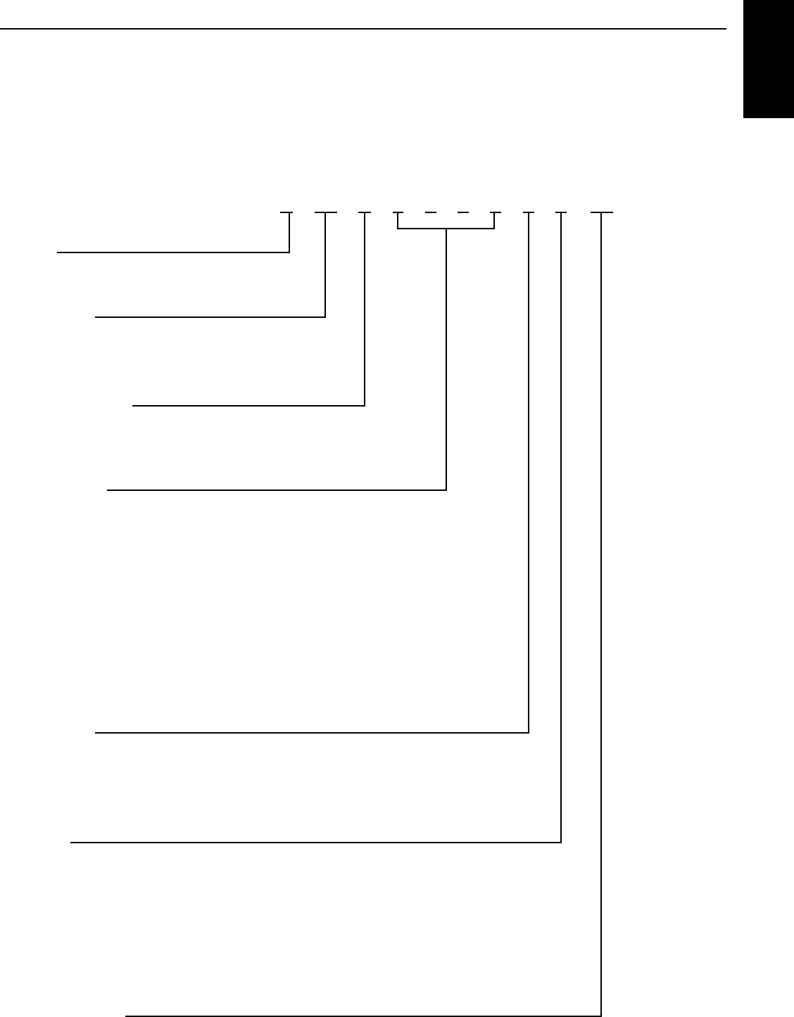
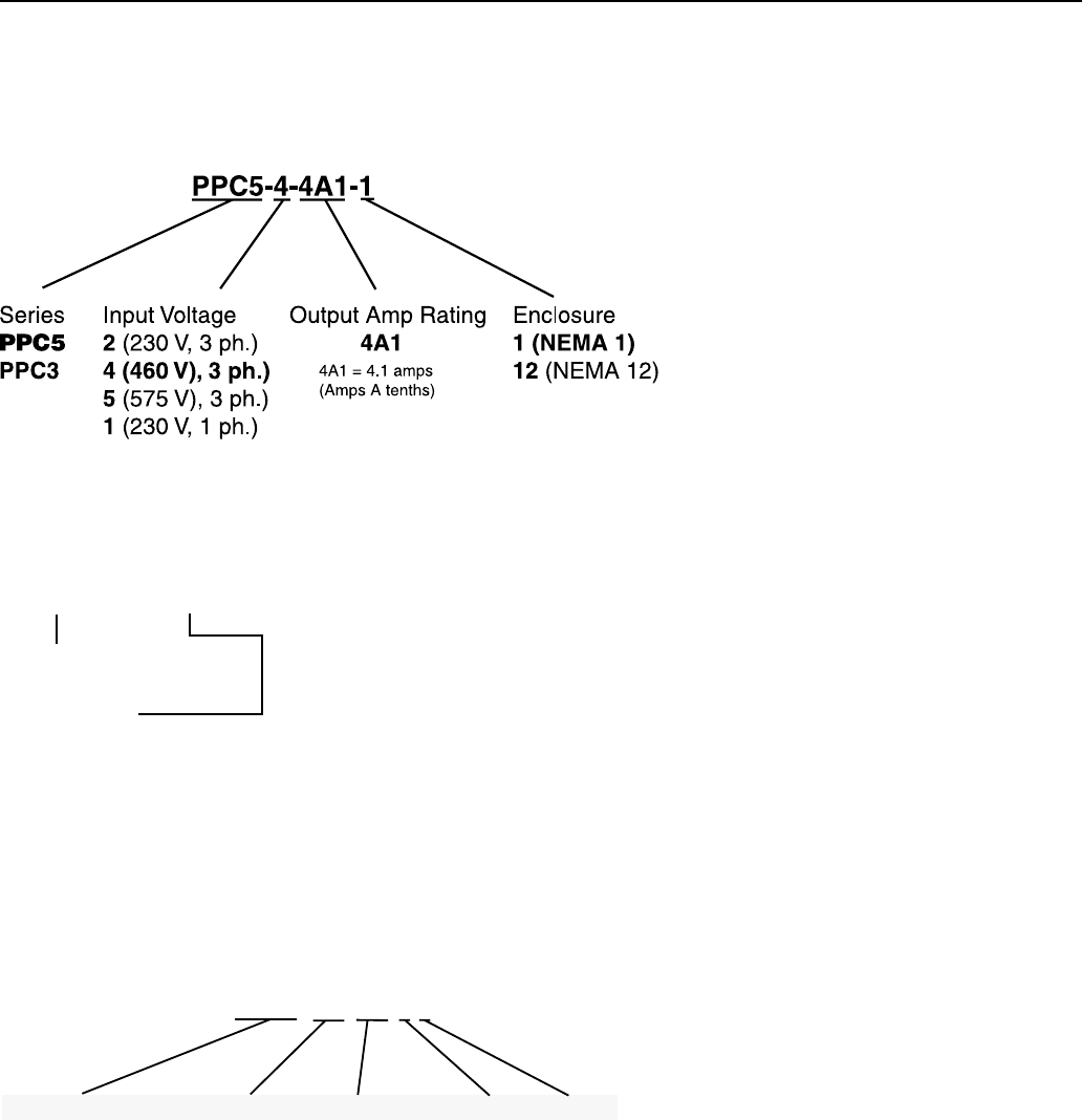
2.2 Drives
Variable / High Speed Drive Nomenclature
The chart below shows the naming for a PPC5, 460 volt,
4amp drive with a NEMA 1 enclosure.
Note that the output current (amps) of the control must
be greater than or equal to the maximum rated motor
current. Output of all drives is 3-phase power.
PID Variable Frequency Drive Nomenclature
2.3 Submersible Motor Controls
The chart below shows the naming for a Submersible
Motor control, Standard box, capacitor run, 5horsepower,
230 volt single phase drive.
Style
CR (Cap Run)
IR (Induction Run)
CRP (Cap Run
with contactor)
Ser
ies
SMC_(Std.
)
SMC5 (50 Hz)
SMC - CR 50 2 1
HP x 10
05 (0.5 hp)
07 (.75 hp)
10 (1 hp)
15 (1.5 hp)
20 (2 hp)
30 (3 hp)
50 (5 hp)
Voltage
1 (115 v)
2 (230 v)
Phase
1 (Single)
HP Rating:
10 = up to 1 HP
20 = up to 2 HP
50 = up to 5 HP
PID – 10
Product Family
PID = Pentek IntelliDrive
6021 0609

5
3.1 General Installation Guidelines
• Inordertoavoidabrasiontothepowerandcontrol
cables, pad the top of the well casing (a rubber pad is
recommended) where the cable will pass over it; use
a cable reel for cable control.
• Theunitmustalwaysbeeasytorotateinthe
hoistinggear.
• Laypowerandcontrolcablesoutstraightonthe
ground (no loops) before installation. Guide cables
during lowering so that they are not stretched or
squeezed while pump is being installed. Make sure
that cable insulation is not nicked or damaged before
or during installation. Never use the electrical cables
to move the motor/pump.
• Thepumpandmotorareheavy.Makesurethatall
connections are secure and that the hoisting gear is
adequate to do the job before starting to lift pump.
Don’t stand under the unit. Don’t allow extra people
into the area while hoisting the unit.
• Ifmotororpump/motorunitareattachedtoa
supporting girder, do not remove girder until unit
isvertical.
• Installpumpatleast10’(3m)belowthelowestwater
level during pumping, but at least 6’ (2m) above the
bottom of the well.
• 6”motorscanbeoperatedinverticalorhorizontal
(when lead wire is at 12:00 position facing motor
flange) positions.
• 4”motorscanbeoperatedinverticalorhorizontal
positions. Note that the thrust bearing will have
shorter life in a non-vertical application. In such an
installation, keep frequency of starts to less than
10perday.
3.2 Proper Grounding
Hazardous voltage. Can shock, burn
or cause death. Installation or service to electrical
equipment should only be done by qualified electrician.
Control panels must be connected to supply ground
Proper grounding serves two main purposes:
1. It provides a path to ground in case of a ground-fault.
Otherwise the current would present a shock or
electrocution hazard.
2. It protects equipment from electrical surges.
Use wire the same size as, or larger than motor’s
current-carrying wires (consult Tables in the motor
section).
Installations must comply with the National Electric Code
as well as state and local codes.
All systems must have lightning (surge) protection with a
secure connection to ground.
An above ground lighting (surge) protection must be
grounded metal-to-metal and extend all the way to
the water bearing layer to be effective. Do not ground
the lightning (surge) protection to the supply ground
or to a ground rod as this will provide little or no surge
protection to the unit.
All motors are internally grounded and requires a 3 or
4-wire drop cable.
3.3 Corrosive Water and Ground
Some waters are corrosive, and can eventually corrode
the ground wire. If the installation uses a metal well
casing, any ground current will flow through it. In the
case of plastic piping and casing, the water column would
carry the current in a ground fault situation.
To prevent this, route the motor ground wire and the
motor power leads through a GFCI with a 10 mA set
point. In this way, the GFCI will trip when a ground fault
has occurred AND the motor ground wire is no longer
functional.
3.4 Check Valves
Check valve installation is necessary for proper pump
operation. The pump should have a check valve on its
discharge, or within 25 feet (7.62 m) of the pump. For very
deep wells, locate a check valve at least every 200 feet
(61m) vertical.
• Useonlyspringtypeorgravity-poppetcheck
valves. Swing type valves can cause water hammer
problems.
• Donotusedrain-backstylecheckvalves(drilled).
Check valves serve the following purposes:
• MaintainPressure:Withoutacheckvalve,thepump
has to start each cycle at zero head, and fill the drop
pipe. This creates upthrust in the motor, and would
eventually damage both the pump and motor.
• PreventWaterHammer:Iftwocheckvalvesareused,
and the lower one leaks, then a partial vacuum forms
in the pipe. When the pump next starts, the flow fills
the void area quickly, and creates a shock wave that
can break piping and damage the pump. If you get
water hammer on pump start, this may be the cause.
• PreventBack-Spin:Withoutafunctioningcheck
valve, upon shutoff, the water drains back through
the pump, and cause it to rotate backwards. This can
create excessive wear on the thrust bearing, and if the
pump restarts as water is flowing down the pipe, it
will put an excessive load on the system.
SECTION 3: Installation and Setup
Installation
and Setup

6
SECTION 3: Installation and Setup
3.5 Start-Up
NOTICE: To avoid sand-locking pump, follow procedure
below when starting pump for the first time. NEVER start
a pump with discharge completely open unless you have
done this procedure first.
1. Connect a pipe elbow, a short length of pipe and a
gate valve to pump discharge at well head.
2. Make sure that controls will not be subjected to
extreme heat or excess moisture.
3. Make sure power is OFF. DO NOT START PUMP YET.
4. Set gate valve on discharge 1/3 open; start pump.
5 Keep gate valve at this setting while water pumps out
on ground. Let it run until water is clear of sand or
silt. (To check solids in water, fill a glass from pump
and let solids settle out).
6. When water is completely clear at 1/3 setting, open
gate valve to approximately two-thirds open and
repeatprocess.
7. When water is completely clear at 2/3 setting, open
gate valve completely and run pump until water is
completely clear.
8. Do not stop the pump until the water is clear.
Otherwise sand will accumulate in the pump stages
which may bind or freeze the pump.
9. Remove gate valve and make permanent installation.
NOTICE: The motor may draw higher than normal current
while the riser pipe is filling. After the riser pipe is full,
the amp draw should drop back to less than the allowed
current given on the motor nameplate.
When pump is in service, the amp draw must be
approximately equal to or lower than the service factor
amps given on the motor nameplate. If not, recheck
entire installation and electrical hook-up to find out why
amp draw is higher than normal.
Motor Torque
The motor exerts a strong torque force on the downpipe
and any other supporting structures when it starts. This
torque is usually in the direction that would unscrew
right-hand threads (the motor’s reaction movement is
clockwise as seen from above).
All pipe and pump joints must be tightened to safely
handle the starting torque. Tighten all threaded
joints to a minimum of 10 ft.-lb per horsepower.
i.e. 20 HP = 200ft.-lb; 50 HP = 500 ft.-lb.
Tack welding or strap welding may be required with
higher horsepower pumps.
7
4.1 Mixing Wire Size with Existing
Installation
Using two different cable sizes.
Sometimes conditions make it desirable to use more
than one size cable, such as replacing a pump in an
existinginstallation.
For example: Installing a pump with a 4”, 5 HP, 230
volt, single phase motor, with the motor setting at 370’
(112.8m) down the well and with 160’ (48.8m) of #8cable
buried between the service entrance and the wellhead.
In order to avoid replacing the buried cable, the question
is: What size cable is required in the well? Calculate
asfollows:
1. According to Table 5-9, a total of 326’ (112.8m) of #8
cable is the maximum length cable to power a 5HP
motor. The percent of this total that has been used
by the 160’ (48.8m) of cable in the buried run is:
160’ / 326’ = .49 or 49%.
2. With 49% of the allowable cable already used, 51%
of the total length is left for use in the well. To avoid
running a cable that is too small (gauge) and lowering
the voltage to the motor, we have to find a cable size
large enough so that 370’ (112.8m) is less than 51%
of the total length allowed for that size.
3. 370 ÷ 51% = 726 feet.
4. From Table 5-9 we find that the total allowable length
for #4 cable is 809’ (246.6 m).
This is longer than needed. Therefore, #4 cable can
be used for the 370’ (112.8m) of cable in the well.
Any combination of sizes can be used, provided that
the total percentage of the length of the two sizes of
cable is not less than 100% of the allowed lengths.
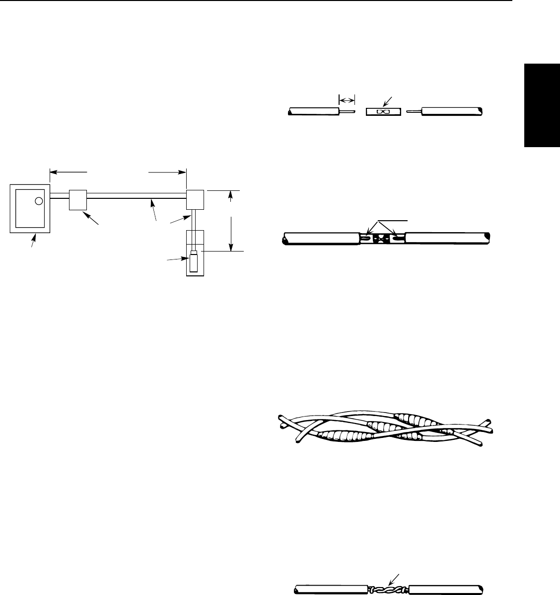
4.2 Wire Splicing
Splice wire to motor leads. Use only copper wire for
connections to pump motor and control box.
1. Taped splice (for larger wire sizes)
A. Stagger lead and wire length so that 2nd lead is
2” (50mm) longer than 1st lead and 3rd lead is
2”(50mm) longer than second.
B. Cut off power supply wire ends. Match colors
and lengths of wires to colors and lengths of
motorleads.
C. Trim insulation back 1/2” (13mm) from supply
wire and motor lead ends (Figure 4-2).
D. Insert motor lead ends and supply wire ends
into butt connectors. Match wire colors between
supply wires and motor leads.
E. Using crimping pliers, indent butt connector lugs
to attach wires (Figure 4-3).
F. Cut Scotchfil™ electrical insulation putty into
3 equal parts and form tightly around butt
connectors. Be sure Scotchfil overlaps insulated
part of wire.
G. Using #33 Scotch® tape, wrap each joint tightly;
cover wire for about 1-1/2” (38mm) on each side
of joint. Make four passes with the tape. When
finished you should have four layers of tape tightly
wrapped around the wire. Press edges of tape
firmly down against the wire (Figure 4-4).
NOTICE: Since tightly wound tape is the only means
of keeping water out of splice, efficiency of splice will
depend on care used in wrapping tape.
NOTICE: For wire sizes larger than No. 8 (7mm2), use
soldered joint rather than Scotchfil putty, Figure 4-5.
Electrical Power
SECTION 4: Electrical Power
Figure 4-1: Mixing Wire Sizes: Example
Cable
Pump
Controls
Ser
vice Entrance
(Main Fuse Box
From Meter)
5 HP (4.9 kw)
230V 1Ph Motor
160 Ft. AWG 8
370 Ft.
5401 0412
Figure 4-2: Insert Wires
1/2"
(12.7mm) Butt Connector
Figure 4-4: Wrap Splices
Completed splice
5186 1105
Alternate method
twist and solder
5187 1105
Figure 4-5: Twist Wires
Indent here
5185 1105
Figure 4-3: Indent Connectors
Scotchfil™ is a trademark of 3M Company.
Scotch is a registered trademark of 3M Company.
8
2. Heat shrink splice (For wire sizes #14, 12 and 10 AWG
(2, 3 and 5mm2):
A. Remove 3/8” (9.5mm) insulation from ends of
motor leads and power supply wires.
B. Put plastic heat shrink tubing over motor leads
between power supply and motor.
C. Match wire colors and lengths between power
supply and motor.
D. Insert supply wire and lead ends into butt
connector and crimp. Match wire colors
between power supply and motor. Pull leads to
checkconnections.
E. Center tubing over butt connector and apply heat
evenly with a torch (match or lighter will not
supply enough heat, Figure 4-6).
NOTICE: Keep torch moving. Too much concentrated heat
may damage tubing.
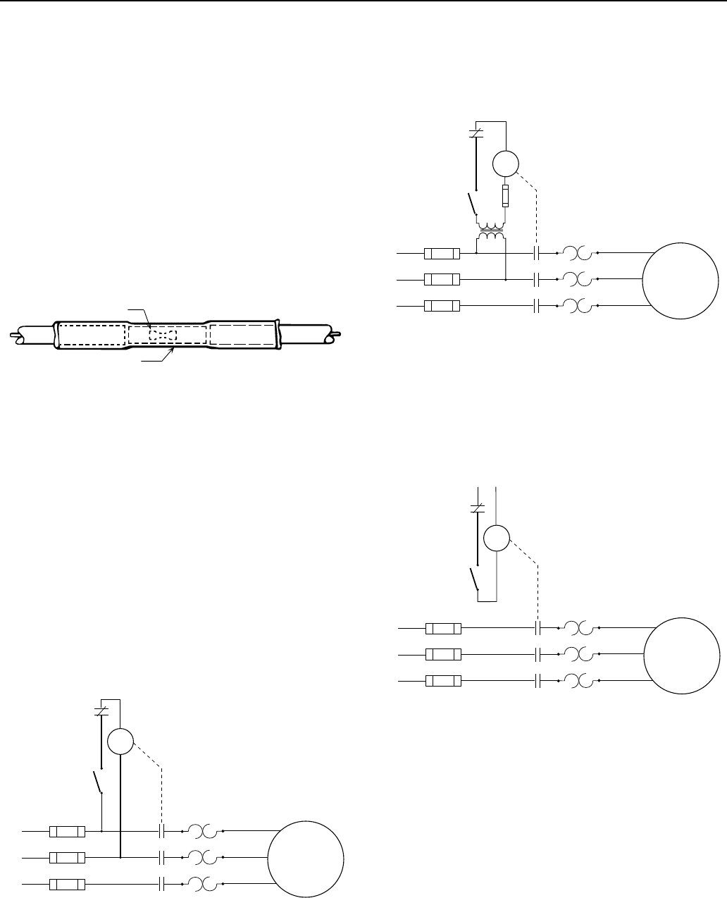
4.3 3-Phase Starters
Starters are used to start the motor by engaging contacts
that will energize each line simultaneously. The contacts
are closed when the coil is energized.
Figures 4-7 through 4-9 show three types of starters used
on the motors. The control device in the secondary circuit
is typically a pressure switch. Other control could be
provided by level control, timers or manual switches.
Line Voltage Control
This commonly-used control has a coil energized by line
voltage. The coil voltage matches the line voltage.
Low Voltage Control
This starter arrangement uses a transformer to allow
the coil to be energized by a lower voltage. Note that the
secondary circuit must be fused, and the coil sized for the
secondary voltage.
Separate Voltage Control
This arrangement uses power from a separate source to
energize the coil.
SECTION 4: Electrical Power
Figure 4-6: Heat-Shrink Tubing Applied
Connector
Heat shrink tubing
5188 1105
Figure 4-8: Low Voltage Control
3-Phase
Motor
L1
L2
L3
Overload
Control
Control
Device
Coil
Thermal
Overload
Heaters
Figure 4-9: Separate Voltage Control
3-Phase
Motor
L1
L2
L3
Overload
Control
Separate
Voltage
Control
Device
Coil
Thermal
Overload
Heaters
Figure 4-7: Line Voltage Control
3-Phase
Motor
L1
L2
L3
Overload
Control
Control
Device
Coil
Thermal
Overload
Heaters
9
4.4 Checking Motor Rotation
To check rotation before the pump is installed, follow
thesesteps:
During testing or checking rotation (such as “bumping”
or “inching”) the number of “starts” should be limited to
3and total run time of less than 15 seconds.
Bumping must be done while motor is in horizontal
position and followed by a full 15 minute cooling-off
period before any additional “starts” are attempted.
Energize the motor
briefly, and observe the
direction of rotation.
It should be counter-
clockwise when viewed
from the pump (shaft)
end.
To check rotation after
the pump is installed:
NOTICE: NEVER
continuously operate a
pump with the discharge
valve completely closed
(dead head). This can overload the motor due to lack of
cooling, or destroy the pump and will void the warranty.
After energizing the motor, check the flow and pressure
of the pump to make sure that the motor is rotating in the
correct direction. To correct a wrong rotation, switch any
two of the three cable connections (three-phase motor
only). The setting that gives the most flow and pressure is
correct.
A cooling-off period of 15 minutes is required
betweenstarts.
Hazardous voltage. Disconnect power
before working on wiring.
Input voltage, current and insulation resistance values
should be recorded throughout the installation and
should be used for preventive maintenance.
4.5 3-Phase Current Balancing
Current Unbalance Test
Before checking for current unbalance, the pump must
be started, and rotation direction determined.
Determine current unbalance by measuring current in
each power lead. Measure current for all three possible
hookups (Figure 4-11). Use example and worksheet on
the Installation Checklist and Record in Section 12 to
calculate current unbalance on a three phase supply
system and retain for future reference.
NOTICE: Current unbalance between leads should not
exceed 5%. If unbalance cannot be corrected by rolling
the leads, locate the source of the unbalance.
Here is an example of current readings at maximum
pump loads on each leg of a three wire hookup. Make
calculations for all three possible hookups.
A. For each hookup, add the readings for the three legs.
B. Divide each total by three to get average amps.
C. For each hookup, find current value farthest from
average (Calculate the greatest current difference
from the average).
D. Divide this difference by the average and multiply by
100 to obtain the percentage of unbalance.
Use smallest percentage unbalance, in this case
Arrangement 2 (Table 4.1).
Us e the Current-Balance worksheet
located in the Installation Record
After trying all three lead hookups, if the reading furthest
from average continues to show on the same power lead,
most of the unbalance is coming from the power source.
Call the power company.
If the reading furthest from average changes leads as the
hookup changes (that is, stays with a particular motor
lead), most of the unbalance is on the motor side of the
starter. This could be caused by a damaged cable, leaking
splice, poor connection, or faulty motor winding.
SECTION 4: Electrical Power
5402 0506
Figure 4-10: Motor Rotation
Starter
Electrical
Power
Supply To Motor
L1
L2
L3
T1
T2
T3
Starter
L1
L2
L3 T1
T2
T3
Arrangement 1
Starter
L1
L2
L3
T1
T2
T3
Arrangement 2 Arrangement 3
Starter
Electrical
Power
Supply To Motor
L1
L2
L3
T1
T2
T3
Starter
L1
L2
L3 T1
T2
T3
Arrangement 1
Starter
L1
L2
L3
T1
T2
T3
Arrangement 2
Arrangement 3
Starter
Electrical
Power
Supply To Motor
L1
L2
L3
T1
T2
T3
Starter
L1
L2
L3 T1
T2
T3
Arrangement 1
Starter
L1
L2
L3
T1
T2
T3
Arrangement 2
Arrangement 3
Figure 4-11: 3-Phase Current Unbalance: Example
Electrical Power
10
Use this worksheet to calculate current unbalance for our
installation.
Table 4-1: Electrical Current Unbalance Example
EXAMPLE
Arrangement 1
Amps
Arrangement 2
Amps
Arrangement 3
Amps
L1–T1=17
L2–T2=15.3
L3–T3=17.7
L1–T3=16.7
L2–T1=16.3
L3–T2=17
L1–T2=16.7
L2–T3=16
L3–T1=17.3
Total Amps 50 50 50
Average Amps 50 ÷ 3 = 16.7 50 ÷ 3 = 16.7 50 ÷ 3 =16.7
From Average Amps
Deviation L1
Deviation L2
Deviation L3
0.3
1.4
1.0
0.0
0.4
0.3
0.0
0.7
0.6
% Current Unbalance
Largest Deviation 1.4 ÷ 16.7 0.4 ÷ 16.7 0.7 ÷ 16.7
% Unbalance + 8.4% 2.4% 4.2%
4.6 Transformer Sizing
A full three-phase power supply is recommended
for all three-phase motors and may consist of three
individual transformers or one three-phase transformer.
“Open” delta or wye connections which use only two
transformers can be used, but are more likely to cause
unbalanced current problems. Transformer ratings
should be no smaller than listed in Table 4-2 for supply
power to the motor alone.
Transformers are rated by KVA capacity. This must be
high enough capacity for the motor being installed. If the
transformer capacity is too small, the motor will receive
reduced voltage and may be damaged.
Any other loads in the system would be in addition to the
motor alone.
Refer to Table 4-2. Note that the open delta configuration
can only use 87% of the rated power of the two
transformers.
SECTION 4: Electrical Power
T1 T2 T3
Wye or Open Delta 3-Phase
T1 T2 T3
Full 3-Phase (Delta)
5060 0705
Table 4-2: Transformer Capacity
HP kW
KVA Rating (smallest) For Each Transformer
Required KVA Open WYE or D
2Transformers
WYE or D
3Transformers
1/2 0.37 1.5 1.0 0.5
3/4 0.55 1.5 1.0 0.5
1 0.75 2.0 1.5 0.75
1-1/2 1.1 3.0 2.0 1.0
2 1.5 4.0 2.0 1.5
3 2.2 5.0 3.0 2.0
5 3.7 7.5 5.0 3.0
7.5 5.5 10.0 7.5 5.0
10 7.5 15.0 10.0 5.0
15 11.0 20.0 15.0 7.5
20 15.0 25.0 15.0 10.0
25 18.5 30.0 20.0 10.0
30 22.0 40.0 25.0 15.0
40 30.0 50.0 30.0 20.0
50 37.0 60.0 35.0 20.0
60 45.0 75.0 40.0 25.0
Figure 4-12: Three Phase Power
11
4.7 Using a Generator
Selecting a generator
Select a generator that can supply at least 65% of rated
voltage upon start-up of the motor.
The chart shows ratings of generators, both externally
and internally regulated. This chart is somewhat
conservative. Consult the generator manufacturer if you
are uncertain.
Table 4-3: Ratings of Generators
Motor Externally Regulated Internally Regulated
HP kW KVA kW KVA
1/2 2.0 2.5 1.5 1.9
3/4 3.0 3.8 2.0 2.5
1 4.0 5.0 2.5 3.1
1-1/2 5.0 6.3 3.0 3.8
2 7.5 9.4 4.0 5.0
3 10.0 12.5 5.0 6.25
5 15.0 18.8 7.5 9.4
7-1/2 20.0 25.0 10.0 12.5
10 30.0 37.5 15.0 18.8
15 40.0 50.0 20.0 25.0
20 60.0 75.0 25.0 31.0
25 75.0 94.0 30.0 37.5
30 100.0 125.0 40.0 50.0
40 100.0 125.0 50.0 62.5
50 150.0 188.0 60.0 75.0
60 175.0 220.0 75.0 94.0
Frequency
It is highly important that the generator maintain
constant frequency (Hz), since the motor’s speed depends
uponfrequency.
A drop of just 1 to 2 Hz can noticeably lower pump
performance. An increase of 1 to 2 Hz can cause
overloadconditions.
Voltage Regulation
There is a significant difference in the performance of
internally and externally regulated generators.
An external regulator senses output voltage dips
and triggers an increase in the voltage output of the
generator.
An internal regulator, senses current and responds to
increased current by supplying more voltage.
Generator Operation
Start the generator before starting the pump motor.
The pump motor must be stopped before turning off
thegenerator.
If the generator runs out of fuel, and the pump is still
connected, it will put excess strain on the thrust bearings
as the generator slows.
Risk of electrocution. Use transfer
switches when the generator is used as a backup to the
power grid. Contact your power company or generator
manufacturer for proper use of standby or backup
generators.
4.8 Special Applications
Using Phase Converters
Phase converters allow three-phase motors to operate
from one-phase supply. Various styles of phase
converters are available. Many converters do not supply
a properly balanced voltage, and using these will void the
motor’s warranty unless approval is obtained first.
Guidelines For Phase Converters:
• Currentunbalancemustbelessthan5%.
• Convertertobesizedtoservicefactorcapacity
• Maintainmotorcoolingwithacoolingflowofatleast
3’ per second.
• Fusesandcircuitbreakersmustbetime-delaytype.
Motor Starting with Reduced Voltage
Starting a motor with full voltage will bring it to full speed
in less than 1/2 second. This can:
• Spiketheloadcurrent,causingbriefvoltagedipsin
other equipment.
• Over-stresspumpandpipingcomponentsbecauseof
high torque.
• Causewaterhammer.
Motor Starters (3-Phase Only)
Various types of motor starters are available.
Autotransformers are recommended because of reduced
current draw.
When motor starters are used, they should supply
a minimum of 55% of rated voltage for adequate
startingtorque.
SECTION 4: Electrical Power
Electrical Power

12
5.1 Motor Inspection
Check the motor for damage in shipping.
Before installation, check the following.
• Checkoveralltools,especiallythehoistinggear,for
wear or damage before hoisting unit.
• Inspectthemotorcableforanynicksorcuts.
• Verifythatmotornameplatedatamatches
registration card information exactly.
• Verifythatmotornameplatevoltageiscorrectfor
available power supply voltage. Voltage must not vary
more than +/-10% from nameplate rated voltage.
• Verifythatthewelldiameterislargeenoughto
accommodate the motor/pump unit all the way to the
pump setting depth.
• Forinstallationswithtightwellcasings,makesure
that riser pipe flanges are recessed to protect
the power and control cables from abrasion and
squeezing during installation.
Heavy object. Lifting equipment must be
capable of lifting motor and attached equipment.
• Ifthetotallengthofthepumpmotorunit(without
any riser pipe) exceeds 10’ (3m), the unit must be
supported with a girder while hoisting. Do not remove
supporting girder until unit is standing vertically in the
hoist. Check for damage.
5.2 Testing
Insulation Resistance
To check for insulation resistance:
1. Disconnect power to the motor for this test.
2. Connect an Ohm meter (resistance in Ω) between the
power leads and the motor ground or well casing.
20KΩ Damaged motor, possible result of
lightning strike.
500KΩ Typical of older installed motor in well.
2 MΩ Newly installed motor
10 MΩ Used motor, measured outside of well
20 MΩ New motor without cable
5.3 Storage and Transportation
The motors are filled with a non-toxic, Propylene Glycol
and water solution to prevent damage from freezing
temperatures. The solution will prevent damage from
freezing temperatures to -40˚F (-40˚ C). Motors should
be stored in areas that do not go below this temperature.
The solution will become slushy between 0˚F (-17˚C) and
-40˚F (-40˚C) but no damage occurs. If this occurs, allow
the motor to sit in the well for several minutes before
operating.
Storage site should be clean, well vented, and cool.
Keep humidity at the storage site as low as possible.
Protect motor and cables from direct sunlight.
Protect power supply cables and control cables from
moisture by taping the cable ends with electrician’s tape.
Do not kink power supply or control cables.
Take care when moving unit (packed or unpacked) with
crane or hoisting gear not to knock it against walls, steel
structure, floors, etc. Do not drop motor.
Do not lift motor or motor/pump unit by power supply or
control cables.
SECTION 5: XE Series 4” Submersible Motors

13
SECTION 5: XE Series 4” Submersible Motors
XE Series Motors
5.4 4” Motor Specifications
Table 5-1: Single Phase Motor Specifications (115 and 230 Volt, 60 Hz, 3450 RPM)
Motor Type Pentek® Part
Number
Full Load Service Factor
Amps (Y/B/R) Y Only Watts Amps (Y/B/R) Y Only Watts
PSC
2-Wire
P42B0010A2-01 7.9 1679 9.1 1990
P42B0015A2-01 9.2 2108 11.0 2520
P42B0005A1-01 7.9 910 9.8 1120
P42B0005A2-01 4.0 845 4.7 1050
P42B0007A2-01 5.0 1130 6.2 1400
P42B0010A2-01 6.7 1500 8.1 1800
P42B0015A2-01 9.0 2000 10.4 2350
P42B0005A1 7.4 845 9.5 1088
P42B0005A2 3.7 834 4.7 1073
P42B0007A2 5.0 1130 6.4 1459
CSIR
3-Wire
P43B0005A1-01 8.8/8.8/0 8.8 675 10.9/10.9/0 10.9 980
P43B0005A2-01 5.3/5.3/0 5.3 740 6.1/6.1/0 6.1 1050
P43B0007A2-01 6.6/6.6/0 6.6 970 7.8/7.8/0 7.8 1350
P43B0010A2-01 8.1/8.1/0 8.1 1215 9.4/9.4/0 9.4 1620
P43B0005A1 11.0/11.0/0 11.0 733 12.6/12.6/0 12.6 1021
P43B0005A2 5.5/5.5/0 5.5 745 6.3/6.3/0 6.3 1033
P43B0007A2 7.2/7.2/0 7.2 1014 8.3/8.3/0 8.3 1381
P43B0010A2 8.4/8.4/0 8.4 1267 9.7/9.7/0 9.7 1672
CSCR
3-Wire
P43B0005A2-01 4.2/4.1/1.8 4.2 7.15 4.8/4.3/1.8 4.8 960
P43B0007A2-01 4.8/4.4/2.5 4.8 940 6.0/4.9/2.3 6.0 1270
P43B0010A2-01 6.1/5.2/2.7 6.1 1165 7.3/5.8/2.6 7.3 1540
P43B0015A2-01 9.1/8.2/1.2 9.1 1660 10.9/9.4/1.1 10.9 2130
P43B0005A2 4.1/4.1/2.2 4.1 720 4.9/4.4/2.1 4.9 955
P43B0007A2 5.1/5.0/3.2 5.1 1000 6.3/5.6/3.1 6.3 1300
P43B0010A2 6.1/5.7/3.3 6.1 1205 7.2/6.3/3.3 7.2 1530
P43B0015A2 9.7/9.5/1.4 9.7 1693 11.1/11.0/1.3 11.1 2187
P43B0020A2 9.9/9.1/2.6 9.9 2170 12.2/11.7/2.6 12.2 2660
P43B0030A2 14.3/12.0/5.7 14.3 3170 16.5/13.9/5.6 16.5 3620
P43B0050A2 24/19.1/10.2 24.0 5300 27.0/22.0/10.0 27 6030

14
SECTION 5: XE Series 4” Submersible Motors
Table 5-2: Three Phase Motor Specifications (230, 460, 200 and 575 Volt, 60 Hz, 3450 RPM)
Pentek® Part
Number
Rating Full Load Maximum Load (SF Load)
HP kW Volts Hz Service
Factor Amps Watts Amps Watts
P43B0005A8
1/2 0.37
200
60
1.6
2.9 600 3.4 870
P43B0005A3 230 2.4 610 2.9 880
P43B0005A4 460 1.3 610 1.5 875
P43B0007A8
3/4 0.55
200
1.5
3.8 812 4.5 1140
P43B0007A3 230 3.3 850 3.9 1185
P43B0007A4 460 1.7 820 2.0 1140
P43B0010A8
1 0.75
200
1.4
4.6 1150 5.5 1500
P43B0010A3 230 4.0 1090 4.7 1450
P43B0010A4 460 2.2 1145 2.5 1505
P43B0015A8
1-1/2 1.1
200
1.3
6.3 1560 7.2 1950
P43B0015A3 230 5.2 1490 6.1 1930
P43B0015A4 460 2.8 1560 3.2 1980
P43B0015A5 575 2 1520 2.4 1950
P43B0020A8
2 1.5
200
1.25
7.5 2015 8.8 2490
P43B0020A3 230 6.5 1990 7.6 2450
P43B0020A4 460 3.3 2018 3.8 2470
P43B0020A5 575 2.7 1610 3.3 2400
P43B0030A8
3 2.2
200
1.15
10.9 2890 12.0 3290
P43B0030A3 230 9.2 2880 10.1 3280
P43B0030A4 460 4.8 2920 5.3 3320
P43B0030A5 575 3.7 2850 4.1 3240
P43B0050A8
5 3.7
200 18.3 4850 20.2 5515
P43B0050A3 230 15.7 4925 17.5 5650
P43B0050A4 460 7.6 4810 8.5 5530
P43B0050A5 575 7.0 5080 7.6 5750
P43B0075A8
7-1/2 5.6
200 27.0 7600 30.0 8800
P43B0075A3 230 24.0 7480 26.4 8570
P43B0075A4 460 12.2 7400 13.5 8560
P43B0075A5 575 9.1 7260 10.0 8310
P43B0100A4 10 7.5 460 15.6 9600 17.2 11000

15
SECTION 5: XE Series 4” Submersible Motors
Table 5-3: Single Phase 4” Motor Electrical Parameters (115 and 230 Volt, 60 Hz, 3450 RPM, 2 and 3 wire)
Motor
Type
Pentek® Part
Number
Winding Efficiency % Power Factor % Locked Rotor
Amps KVA Code
Main
Resistance *
Start
Resistance FL SF FL SF
PSC
2-Wire
P42B0005A1-01 1.4-2.0 42.1 54 99.6 99.9 28 H
P42B0005A2-01 6.1-7.2 45 58.5 92 97 16 J
P42B0007A2-01 5.9-6.9 50.5 61
98 98 18 F
P42B0010A2-01 4.2-5.2 50 59 24
P42B0015A2-01 1.8-2.4 56.5 62.5
99
44 H
P42B0005A1 1.3-1.8 49 61 99 36.4 K
P42B0005A2 4.5-5.2 50 62 97 19.5
P42B0007A2 3.0-4.8 55 65 24.8 J
P42B0010A2 4.2-5.2 58 94 96 21.7 F
P42B0015A2 1.9-2.3 59 64 99 99 42 H
CSIR
3-Wire
P43B0005A1-01 1.0-1.4 2.5-3.1 57 62 65 78 44 M
P43B0005A2-01 5.1-6.1 12.4-13.7 52 58.5 61 75 21
LP43B0007A2-01 2.6-3.3 10.4-11.7 60 64.5 64 76 32
P43B0010A2-01 2.0-2.6 9.3-10.4 63 66 66 41
P43B0005A1 0.9-1.6 5.7-7.0 51 59 54 69 49.6 N
P43B0005A2 4.2-4.9 17.4-18.7 50 58 58 71 22.3 M
P43B0007A2 2.6-3.6 11.8-13.0 55 61 61 72 32
L
P43B0010A2 2.2-3.2 11.3-12.3 59 62 66 75 41.2
CSCR
3-Wire
P43B0005A2-01 5.1-6.1 12.4-13.7 54.5 61.5 77 87 21
P43B0007A2-01 2.6-3.3 10.4-11.7 62 69 86 91 32
P43B0010A2-01 2.0-2.6 9.3-10.4 66 71 86 41
P43B0015A2-01 2.1-2.5 10.0-10.8 68 69 81 87 49 J
P43B0005A2 4.2-4.9 17.4-18.7 52 62 76 85 22.3 M
P43B0007A2 2.6-3.6 11.8-13.0 56 65 85 90 32 L
P43B0010A2 2.2-3.2 11.3-12.3 62 68 86 92 41.2
P43B0015A2 1.6-2.3 7.9-8.7 66 67 80 85 47.8 J
P43B0020A2 1.6-2.2 10.8-12.0 68 69 96 95 49.4 G
P43B0030A2 1.1-1.4 2.0-2.5 72 72 97 76.4
P43B0050A2 0.62-0.76 1.36-1.66 71 71 97 98 101 E
* Main winding is between the yellow and black leads. Start winding is between the yellow and red leads.
XE Series Motors

16
SECTION 5: XE Series 4” Submersible Motors
Table 5-4: T
hree Phase
Motor Electrical Parameters (230, 460, 200 and 575 Volt, 60 Hz, 3450 RPM)
Pentek® Part
Number Line to Line Resistance Ohms % Efficiency Locked Rotor Amps KVA Code
FL SF
P43B0005A8 4.1-5.2 62 68.5 22
R
P43B0005A3 5.72-7.2 61 68 17.3
P43B0005A4 23.6-26.1 9
P43B0007A8 2.6-3.0 69 74 32
P43B0007A3 3.3-4.3 66 71 27
P43B0007A4 14.4-16.2 69 73.5 14
P43B0010A8 3.4-3.9 66 70 29
MP43B0010A3 4.1-5.1 69 72 26.1
P43B0010A4 17.8-18.8 65 69 13
P43B0015A8 1.9-2.5 72 74 40
LP43B0015A3 2.8-3-4 75 76 32.4
P43B0015A4 12.3-13.1 72 73 16.3
P43B0015A5 19.8-20.6 73 74 11.5 J
P43B0020A8 1.4-2.0 74
75
51
KP43B0020A3 1.8-2.4 75 44
P43B0020A4 8.00-8.67 74 23
P43B0020A5 9.4-9.7 78 78 21.4 M
P43B0030A8 0.9-1.3 77 77
71 K
P43B0030A3 1.3-1.7 58.9
J
P43B0030A4 5.9-6.5 76 30
P43B0030A5 9.4-9.7 78 78 21.4
P43B0050A8 0.4-0.8 76 76 113
P43B0050A3 .85-1.25 93
P43B0050A4 3.58-4.00 77 77 48
P43B0050A5 3.6-4.2 75 75 55 M
P43B0075A8 0.5-0.6 74 74 165 J
P43B0075A3 0.55-0.85 75 75 140
P43B0075A4 1.9-2.3 76 76 87 L
P43B0075A5 3.6-4.2 77 77 55 J
P43B0100A4 1.8-2.2 79 80 110 K

17
SECTION 5: XE Series 4” Submersible Motors
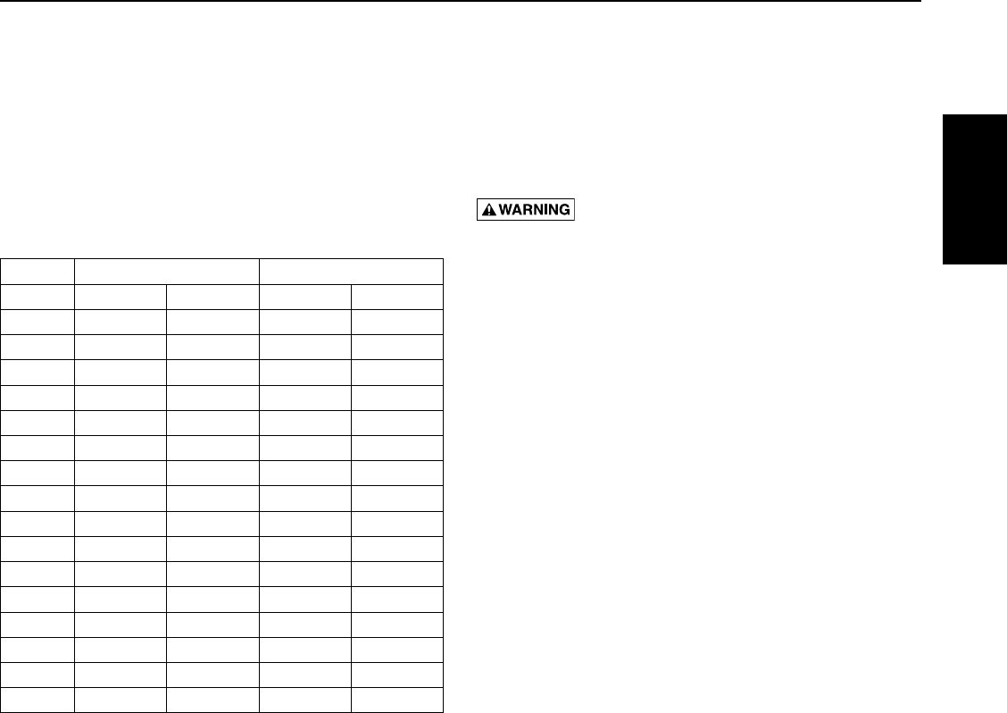
5.5 4” Motor Dimensions
Table 5-5: Single Phase Motor Dimensions (115 and 230 Volt, 60 Hz, 3450 RPM)
Motor Type Pentek® Part
Number HP kW Length Weight
Inches mm Lb Kg
4-Inch
2-Wire
P42B0005A1-01 1/2 0.37 10.5 267 18.1 8.2
P42B0005A2-01
P42B0007A2-01 3/4 0.55 11.9 302 21.4 9.7
P42B0010A2-01 1 0.75 12.5 318 23.2 10.5
P42B0015A2-01 1-1/2 1.1 14.2 361 27.3 12.4
P42B0005A1 1/2 0.37 11.0 279 19.2 8.7
P42B0005A2
P42B0007A2 3/4 0.55 12.4 314 22.7 10.3
P42B0010A2 1 0.75 13.3 337 24.5 11.1
P42B0015A2 1-1/2 1.1 14.9 378 28.9 13.1
4-inch
3-Wire
P43B0005A1-01 1/2 0.37 9.6 244 17.9 8.1
P43B0005A2-01 9.2 234 16.7 7.6
P43B0007A2-01 3/4 0.55 10.3 262 19.8 9.0
P43B0010A2-01 1 0.75 11.2 284 22.0 10.0
P43B0005A1 1/2 0.37 10.0 253 18.9 8.6
P43B0005A2 9.7 246 18.1 8.2
P43B0007A2 3/4 0.55 10.8 275 21.4 9.7
P43B0010A2 1 0.75 11.7 297 23.1 10.5
P43B0005A2-01 1/2 0.37 9.2 234 16.7 7.6
P43B0007A2-01 3/4 0.55 10.3 262 19.8 9.0
P43B0010A2-01 1 0.75 11.2 284 22.0 10.0
P43B0015A2-01 1-1/2 1.1 12.8 325 26.0 11.8
P43B0005A2 1/2 0.37 9.7 246 18.1 8.2
P43B0007A2 3/4 0.55 10.8 275 21.4 9.7
P43B0010A2 1 0.75 11.7 297 23.1 10.5
P43B0015A2 1-1/2 1.1 13.6 345 27.4 12.4
P43B0020A2 2 1.5 15.1 383 31.0 14.1
P43B0030A2 3 2.2 18.3 466 40.0 18.1
P43B0050A2 5 3.7 27.7 703 70.0 31.8
XE Series Motors

18
SECTION 5: XE Series 4” Submersible Motors
Table 5-6: Three Phase Motor Dimensions (230, 460, 200 and 575 Volt, 60 Hz, 3450 RPM)
Pentek® Part Number HP kW Length Weight
Inches mm Lb Kg
P43B0005A8
1/2 0.37 10 254 18.9 8.6P43B0005A3
P43B0005A4
P43B0007A8
3/4 0.55 10.8 275 21.4 9.7P43B0007A3
P43B0007A4
P43B0010A8
1 0.75
11.7 297 23.1 10.5
P43B0010A3
P43B0010A4
P43B0015A8
1-1/2 1.1
P43B0015A3
P43B0015A4
P43B0015A5
P43B0020A8
2 1.5 13.8 351 27.4 12.4P43B0020A3
P43B0020A4
P43B0020A5
15.3 389 32 14.5
P43B0030A8
3 2.2
P43B0030A3
P43B0030A4
P43B0030A5
P43B0050A8
5 3.7 21.7 550 55 24.9P43B0050A3
P43B0050A4
P43B0050A5
27.7 703 70 31.8
P43B0075A8
7-1/2 5.6
P43B0075A3
P43B0075A4
P43B0075A5
P43B0100A4 10 7.5 30.7 780 78 35.4
19
SECTION 5: XE Series 4” Submersible Motors
3.00 (7.62)
1.508 (38.30)
1.498 (38.05)
0.6255 (15.89)
0.6245 (15.86)
14 Teeth 24/48 Pitch
30 Degee Pressure Angle
Min 0.50 (23.1) Full Spline
ANSI B92.1 Compliant
(4) 5/16 - 24
UNF-2A Threaded
Studs on 3” (76.2)
Dia. Circle
Sand Boot
3.750 (95.2)
1.5 (38.1)max.
Length
4” Motor
All dimensions
in inches (mm)
Shaft free end-play
.005 -.040 (.127 - 1.02)
0.97 (24.6) max
0.79 (20.1) min
Figure 5-1: XE Series 4” Motor Dimensions – Single and Three Phase
XE Series Motors

20
SECTION 5: XE Series 4” Submersible Motors
5.6 4” Motor Fuse Sizing
Table 5-7: SINGLE PHASE Motor Fuse Sizing (115 and 230 Volt, 60 Hz, 3450 RPM)
Motor Type Pentek® Part Number HP kW Volts
Fuse Sizing Based on NEC
Standard Fuse Dual Element Time Delay Fuse Circuit
Breaker
4-Inch
PSC
2-Wire
P42B0005A1-01 1/2 0.37 115 30 20 25
P42B0005A2-01
230
15 10 15
P42B0007A2-01 3/4 0.55 20 15 20
P42B0010A2-01 1 0.75 25
P42B0015A2-01 1-1/2 1.1 35 20 30
P42B0005A1 1/2 0.37 115 25 15 20
P42B0005A2
230
15 10 10
P42B0007A2 3/4 0.55 20 15
P42B0010A2 1 0.75 25 15 20
P42B0015A2 1-1/2 1.1 30 25
4-Inch
CSIR
3-Wire
P43B0005A1-01 1/2 0.37 115 30 20 30
P43B0005A2-01
230
15 10 15
P43B0007A2-01 3/4 0.55 20 20
P43B0010A2-01 1 0.75 25 15 25
P43B0005A1 1/2 0.37 115 30 20 30
P43B0005A2
230
15 10 15
P43B0007A2 3/4 0.55 20 20
P43B0010A2 1 0.75 25 15 25
4-Inch
CSCR
3-Wire
P43B0005A2-01 1/2 0.37 15
10
10
P43B0007A2-01 3/4 0.55 20 15
P43B0010A2-01 1 0.75
P43B0015A2-01 1-1/2 1.1 30 15 25
P43B0005A2 1/2 0.37 15
10
10
P43B0007A2 3/4 0.55 20 15
P43B0010A2 1 0.75
P43B0015A2 1-1/2 1.1 30 15 25
P43B0020A2 2 1.5 30 20 25
P43B0030A2 3 2.2 45 25 40
P43B0050A2 5 3.7 70 40 60

21
SECTION 5: XE Series 4” Submersible Motors
Table 5-8: THREE PHASE Motor Fuse Sizing (230, 460, 200 and 575 Volt, 60 Hz, 3450 RPM)
Pentek®
Part Number HP kW Volts
Fuse Sizing Based on NEC
Standard
Fuse Dual Element Time Delay Fuse Circuit
Breaker
P43B0005A8
1/2 0.37
200 10 6 10
P43B0005A3 230 6 6 6
P43B0005A4 460 3 3 3
P43B0007A8
3/4 0.55
200 15 10 10
P43B0007A3 230 6 6 6
P43B0007A4 460 3 6 3
P43B0010A8
1 0.75
200 15 10 10
P43B0010A3 230 10 6 10
P43B0010A4 460 6 3 6
P43B0015A8
1-1/2 1.1
200 20 10 15
P43B0015A3 230 15 10 15
P43B0015A4 460 10 6 6
P43B0015A5 575 6 3 6
P43B0020A8
2 1.5
200 25 15 20
P43B0020A3 230 15 15 20
P43B0020A4 460 15 6 10
P43B0020A5 575 10 6 10
P43B0030A8
3 2.2
200 35 20 30
P43B0030A3 230 25 15 25
P43B0030A4 460 15 10 15
P43B0030A5 575 10 10 10
P43B0050A8
5 3.7
200 60 35 50
P43B0050A3 230 45 30 40
P43B0050A4 460 25 15 20
P43B0050A5 575 20 15 20
P43B0075A8
7-1/2 5.6
200 80 50 70
P43B0075A3 230 70 45 60
P43B0075A4 460 40 25 35
P43B0075A5 575 25 20 25
P43B0100A4 10 7.5 460 45 25 35
XE Series Motors

22
SECTION 5: XE Series 4” Submersible Motors
5.7 Cable Lengths
Ta ble 5-9: Cable Lengths, SINGLE PHASE 115 and 230 Volt, 60 Hz, 3450 RPM, 2- and 3-wire Motors, 60° and 75° C.
Service Entrance to Motor: Maximum Length in Feet
Motor
Type
Pentek® Part
Number HP Volt Wire Size, AWG
14 12 10 8 6 4 3 2 1 0 00
PSC
2-Wire
P42B0005A1-01 1/2 115 112 178 284 449 699 1114 1401 1769 2229 2814 3550
P42B0005A2-01
230
464 739 1178 1866 2903 4628 5818 7347 9256 11684
P42B0007A2-01 3/4 353 562 897 1420 2210 3523 4429 5594 7046 8895 11222
P42B0010A2-01 1 271 430 686 1087 1692 2697 3390 4281 5394 6808 8590
P42B0015A2-01 1-1/2 211 335 535 847 1318 2100 2640 3335 4201 5303 6690
P42B0005A1 1/2 115 115 183 293 463 721 1150 1445 1825 2299 2902 3662
P42B0005A2
230
466 742 1183 1874 2915 4648 5843 7379 9295 11733
P42B0007A2 3/4 342 545 869 1376 2141 3413 4291 5419 6826 8617 10871
P42B0010A2 1 241 383 611 968 1506 2400 3018 3811 4801 6060 7646
P42B0015A2 1-1/2 199 317 505 801 1246 1986 2496 3153 3972 5013 6325
CSIR
3-Wire
P43B0005A1-01 1/2 115 101 160 255 404 629 1002 1260 1591 2004 2530 3192
P43B0005A2-01
230
359 571 912 1444 2246 3581 4502 5685 7162 9040
P43B0007A2-01 3/4 281 447 713 1129 1757 2800 3521 4446 5601 7070 8920
P43B0010A2-01 1 233 371 592 937 1458 2324 2921 3689 4648 5867 7402
P43B0005A1 1/2 115 87 138 221 349 544 867 1090 1376 1734 2188 2761
P43B0005A2
230
348 553 883 1398 2175 3467 4359 5505 6935 8753
P43B0007A2 3/4 264 420 670 1061 1651 2632 3309 4178 5264 6644 8383
P43B0010A2 1 226 359 573 908 1413 2252 2831 3575 4504 5685 7173
CSCR
3-Wire
P43B0005A2-01 1/2 457 726 1158 1835 2855 4551 5721 7225 9102 11489
P43B0007A2-01 3/4 365 581 927 1468 2284 3641 4577 5780 7281 9191 11596
P43B0010A2-01 1 300 478 762 1206 1877 2992 3762 4751 5985 7554 9531
P43B0015A2-01 1-1/2 201 320 510 808 1257 2004 2519 3182 4008 5059 6383
P43B0005A2 1/2 447 711 1135 1797 2796 4458 5604 7078 8916 11254
P43B0007A2 3/4 348 553 883 1398 2175 3467 4359 5505 6935 8753 11044
P43B0010A2 1 304 484 772 1223 1903 3034 3814 4817 6068 7659 9663
P43B0015A2 1-1/2 197 314 501 793 1234 1968 2474 3124 3936 4968 6268
P43B0020A2 2 180 286 456 722 1123 1790 2251 2843 3581 4520 5703
P43B0030A2 3 133 211 337 534 830 1324 1664 2102 2648 3342 4217
P43B0050A2 5 206 326 507 809 1017 1284 1618 2042 2577
* Table data are generated per NEC standards.

23
SECTION 5: XE Series 4” Submersible Motors
Ta ble 5-10: Cable Lengths, THREE PHASE 230, 460, 200 and 575 Volt, 60 Hz, 3450 RPM Motors, 60° and 75° C.
Service Entrance to Motor: Maximum Length in Feet
Pentek® Part
Number HP Volt Wire Size, AWG
14 12 10 8 6 4 3 2 1 0 00
P43B0005A8
1/2
200 657 1045 1667 2641 4109
P43B0005A3 230 756 1202 1917 3037 4725 7532 9469
P43B0005A4 460 2922 4648 7414
P43B0007A8
3/4
200 423 674 1074 1702 2648
P43B0007A3 230 562 894 1426 2258 3513 5601 7041 8892
P43B0007A4 460 2191 3486 5560 8806
P43B0010A8
1
200 346 551 879 1392 2166 3454 4342
P43B0010A3 230 466 742 1183 1874 2915 4648 5843 7379
P43B0010A4 460 1753 2789 4448 7045
P43B0015A8
1-1/2
200 265 421 672 1064 1655 2638 3317
P43B0015A3 230 359 571 912 1444 2246 3581 4502 5685 7162 9040
P43B0015A4 460 1370 2179 3475 5504
P43B0015A5 575 2283 3631 5792
P43B0020A8
2
200 217 344 549 870 1354 2158 2714 3427 4317 5449
P43B0020A3 230 288 459 732 1159 1803 2874 3613 4563 5748 7256 9155
P43B0020A4 460 1153 1835 2926 4635 7212
P43B0020A5 575 1336 2126 3390 5370
P43B0030A8
3
200 159 253 403 638 993 1583 1990 2513 3166 3996
P43B0030A3 230 217 345 551 872 1357 2163 2719 3434 4326 5460 6889
P43B0030A4 460 827 1315 2098 3323 5171
P43B0030A5 575 1660 2641 4212 6671
P43B0050A8
5
200 94 150 239 379 590 940 1182 1493 1881 2374 2995
P43B0050A3 230 125 199 318 503 783 1248 1569 1982 2496 3151 3976
P43B0050A4 460 516 820 1308 2072 3224 5140
P43B0050A5 575 721 1147 1829 2897 4507
P43B0075A8
7-1/2
200 64 101 161 255 397 633 796 1005 1266 1598 2017
P43B0075A3 230 211 334 519 827 1040 1314 1655 2089 2635
P43B0075A4 460 325 516 824 1305 2030 3236 4068 5138 6472
P43B0075A5 575 548 871 1390 2202 3426
P43B0100A4 10 460 255 405 647 1024 1593 2540 3193 4033 5080
* Table data are generated per NEC standards.
XE Series Motors
24
SECTION 5: XE Series 4” Submersible Motors
5.8 4” Motor Overload Protection
Single Phase Motors
Single phase motors have overload protection either
in the motor or in the control box. Motors less than or
equal to 1HP have built-in protection. This automatic
protection will continue to cycle under a locked or stalled
rotorcondition.
Single phase motors larger than 1 HP use overload
protection located in the SMC (Submersible Motor
Controls) section. These are manual overloads and must
be manually reset if an overload condition occurs.
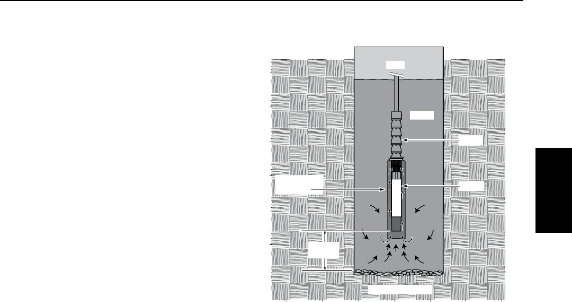
5.9 Motor Cooling
Pentek® 4” XE Series motors are designed to operate to a
maximum SF (Service Factor) horsepower in water up to
86° F (30° C).
4” motors: Minimum cooling water flow 3 HP and over
I.D of casing Flow GPM (LPM) required
41.2 (4.5
57 (26.5)
613 (49)
720 (76)
830 (114)
10 50 (189)
12 80 (303)
14 110 (416)
16 150 (568)
If the flow is less than specified, a flow-inducer sleeve
can be installed, as shown in Figure 5-2. The sleeve will
act like a smaller casing size to force flow around the
motor to aidcooling.
5.10 Starting Frequency
Recommended motor starting frequency is shown
below. Motor, pressure switch, tank, and pump life may
be extended by limiting starts per hour and starts per
day. Proper tank sizing is critical to control pump cycle
times. Excessive or rapid cycling creates heat which can
prematurely damage motors, switches, andcontrols.
Motor Starting Frequency
HP Single Phase Three Phase
Starts/hr Starts/24hr Starts/hr Starts/24hr
1/2 thru 3/4 12.5 300 12.5 300
1 thru 5 4.2 100
7.5 thru 200 4.2 100
A one (1) minute minimum run time for pumps and motors up to 1.5HP and
two (2) minutes for 2HP and larger motors is recommended to dissipate heat
build-up from starting current.
Figure 5-2: Flow Inducer Sleeve

25
SECTION 6: Pentek® 6” Submersible Motors
6.1 Motor Inspection
Important Safety Instructions
SAVE THESE INSTRUCTIONS - This manual contains
important instructions that should be followed during
installation, operation, and maintenance.
This is the safety alert symbol. When you see this
symbol in this manual, look for one of the following
signal words and be alert to the potential for personal
injury!
indicates a hazard which, if not avoided, will
result in death or serious injury.
indicates a hazard which, if not avoided,
could result in death or serious injury.
indicates a hazard which, if not avoided,
could result in minor or moderate injury.
NOTICE addresses practices not related to
personalinjury.
Carefully read and follow all safety instructions in this
manual.
Keep safety labels in good condition. Replace missing
or damaged safety labels.
California Proposition 65 Warning
This product and related accessories
contain chemicals known to the State of California to
cause cancer, birth defects or other reproductive harm.
APPLICATION LIMITS
Maximum Immersion Depth: 985 ft. (300 m)
Maximum Water Temperature: 95°F (35°C)
pH content of the water: 6.5–8
Minimum Cooling Flow Rate: 0.5 feet per second (fps)
(0.15meters per second (mps)).
Required line voltage at the motor under operating
conditions (±10%).
NOTICE When calculating voltage at the motor, be sure
to allow for voltage drop in the cable.
The sum of the absolute values of the voltage and
frequency must not vary from the sum of the nominal
values by more than ±10%.
Operating with current unbalanced on the three legs of
the circuit can overheat and damage the motor and will
void the warranty. Current imbalance must not exceed
5% maximum.
Maximum Sand Content: 50ppm (max. size 0.1–0.25mm)
Maximum Chlorine Ion Content: 500ppm
6.2 Testing
ELECTRICAL
(See Table 1, Page 4, for Motor Electrical
Specifications)
1. Risk of electrical shock if the cable is
damaged. Inspect the motor cable for any nicks or
cuts. Do not use the motor cable to pull, lift, or
handle the motor. Protect the motor cable during
storage, handling, moving, and installation of the
motor.
2. Inspect the motor to determine that it is the correct
horsepower, voltage, and size for the job and that
there is no shipping damage. Verify that the motor
nameplate voltage matches the available power
supply voltage. The nameplate rated voltage must
not vary more than ± 10% from the power supply
voltage.
3. On all new installations and after the motor has
sat idle for a long period of time, check the motor’s
internal electrical resistance with a megohmmeter
with lead wires connected. Prior to installation, the
motor should have an insulation value of at least
500 megohms. After installation, the motor and
power cable should have a minimum insulation
value of 1 megohm. If the minimum values are
below the listed values, contact the factory before
starting the motor.
4. Fuses or circuit breakers and overload protection
are required. Fuses or circuit breakers and
overloads must be sized in accordance with National
Electrical Code (NEC) or Canadian Electrical Code
(CEC) requirements, as applicable, and with all
applicable local codes and ordinances. See
Section 6 for these specifications.
5. Wire and ground the motor in accordance with
National Electrical Code (NEC) or Canadian
Electrical Code (CEC) requirements, as applicable,
and with all applicable local codes and ordinances.
6.3 Storage and Drain/Fill Instructions
LIFTING
1. Heavy Object. Lifting equipment must be
capable of lifting motor and attached equipment. Check
over all tools, especially the hoisting gear, for wear or
damage before hoisting the unit.
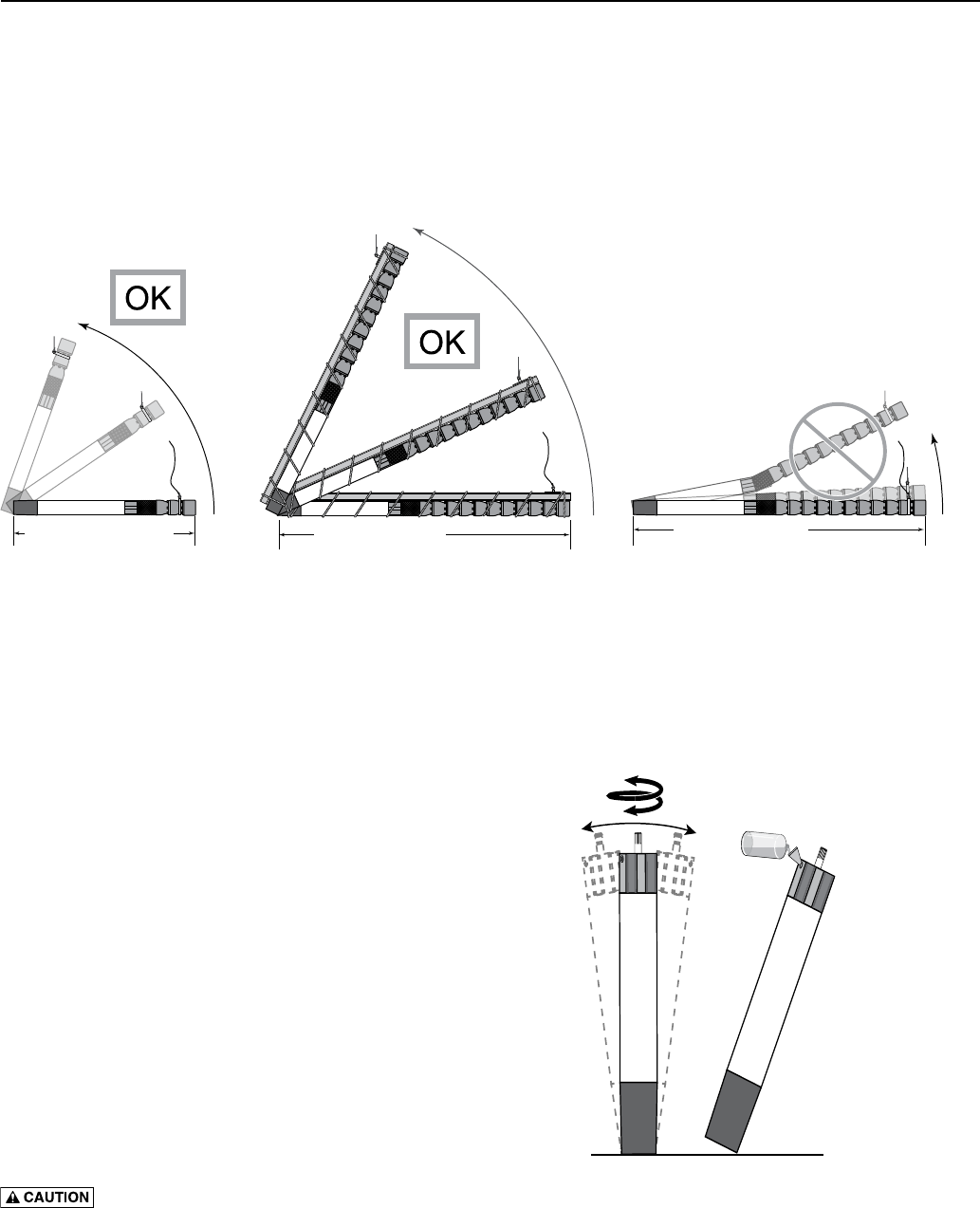
2. If the total length of the pump and motor unit (without
any riser pipe attached) exceeds 10ft (3m), support the
unit with a girder while hoisting (see Figure 1). Do not
remove the supporting girder until the unit is standing
vertically in the hoist. Check for damage.
Pentek 6” Motors
26
SECTION 6: Pentek® 6” Submersible Motors
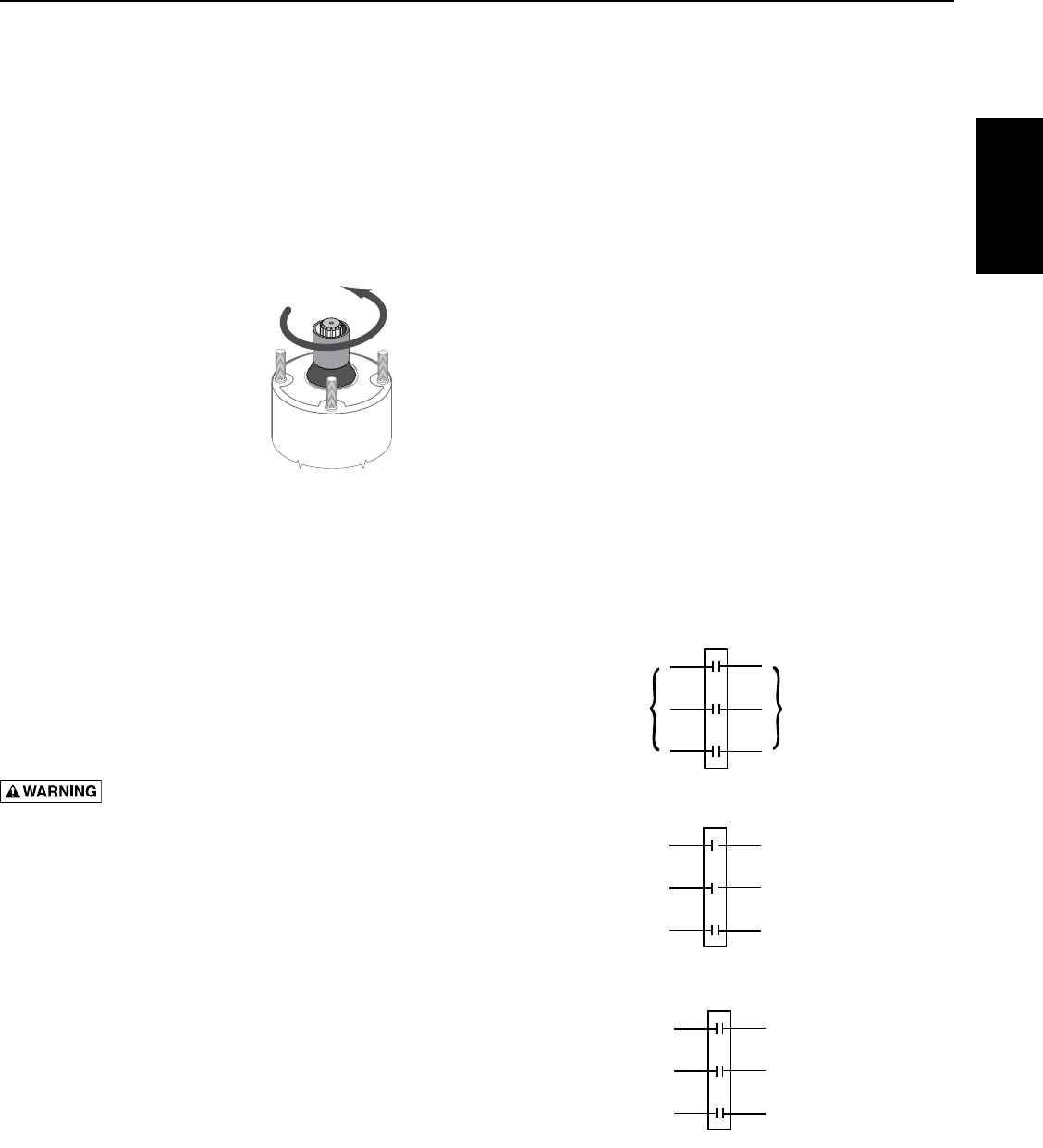
6.3 Storage and Drain/Fill Instructions
MOTOR STORAGE AND INSTALLATION
1. The motor is filled at the factory with anti-freeze
which will protect it in temperatures down to –22ºF
(-30ºC). Do not install, transport or store the motor
below these temperatures if the motor is filled. If
storage is necessary at temperatures below –22ºF
(-30ºC), drain the anti-freeze from the motor.
2. Verify that the motor is full before installing. If not, fill
it with clean water (see below). Installing a motor that
is not filled with liquid will void the warranty. Before
installation, check all water fill and drain plugs,
mounting bolts, and cable connections for tightness.
Refill the motor with clean water as follows:
A. Stand the motor on end (vertically) and remove the
fill plug with a 5mm hexagonal nut driver.
B. Turn the motor shaft by hand while rocking the
motor back and forth (see Figure 2).
C. Pour in clean water until the motor is as full as
possible.
D. Repeat the turning/rocking procedure.
E. Check the liquid level. If necessary, add more clean
water.
F. When the motor is full, re-install the fill plug.
Tighten it with the 5mm hexagonal nut driver.
Support motor while rocking to prevent motor
from falling over.
A. Rock motor
while turning
shaft.
B. Fill motor;
repeat rocking
and lling until
motor is full.
Figure 2: Rock Motor gently from side to side while
turning shaft by hand (A), then fill with clean water (B).
Repeat until full.
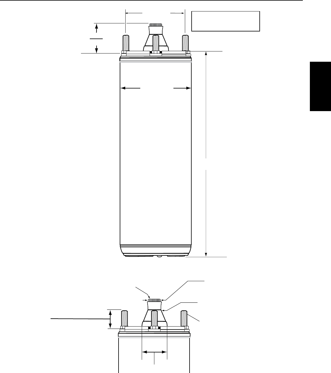
Less Than 10 Ft (3 M) 10 Ft (3M) or More 10 Ft (3M) or More
Support the pump and motor! Lack of support will destroy the motor!
Figure 1: When the pump and motor together
(without any riser pipe) are 10ft (3m) long or more,
support the assembly before lifting to avoid bending
it in the middle. Never try to lift the motor or pump
by the motor cables.
27
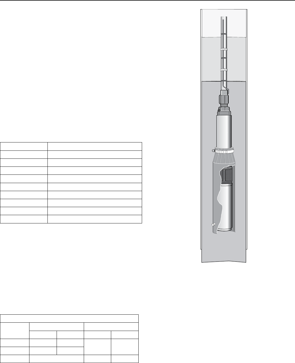
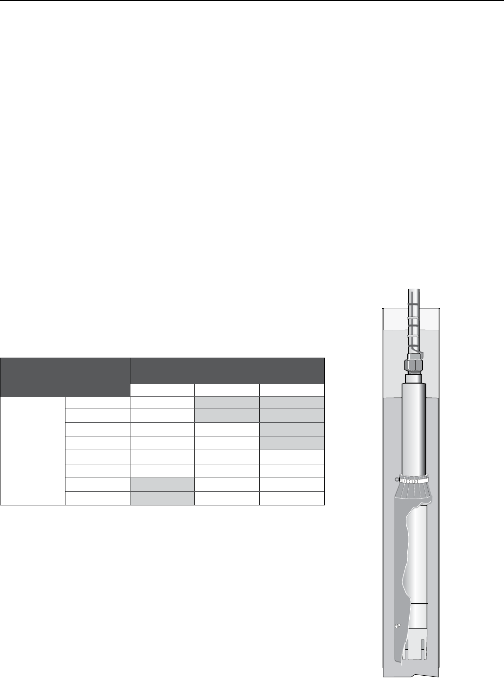
10’ (3M)
or more
Well
Water
Flow Inducer
Sleeve Motor
Pump
NOT TO SCALE
Figure 3: If flow past motor is less than .5 fps (0.15 mps),
install a flow inducer sleeve as shown. Flow must be at
least .5 fps (0.15 mps) for adequate motor cooling. The
flow inducer sleeve should not touch the side of the
motor.
SECTION 6: Pentek® 6” Submersible Motors
6.3 Storage and Drain/Fill Instructions
NOTICE To avoid damaging the motor thrust bearing,
do not hammer on the shaft, coupling, or slinger. Check
the motor rotation by hand to make sure that it turns
freely.
1. To avoid damage to the motor diaphragm, make
sure that the bottom of the motor does not touch
the dirt or mud at the bottom of the well. Install the
motor at least 10’ above the well bottom.
2. To install the motor horizontally, lay it down with
the lead wires at 12 o’clock when you are facing
the motor shaft. To prevent any load on the shaft
and bearings and to avoid any damaging vibrations
to the motor, mount the motor solidly on the pump
end and make sure that the pump and motor are
accurately aligned.
3. Install the motor so that during operation water
flows past all parts of it at a rate of at least 0.5 fps
(0.15 mps). If the well will not provide this flow,
install a sleeve on the motor to channel water past
it (see Figure 3). Do not try to operate the motor in
mud or sand. To do so will damage the motor and
void the warranty.
4. Electrical connections: Connect the three motor
leads to the three hot motor leads (black, brown,
and blue) in the incoming cable. Connect the
ground wire (green and yellow) in accordance with
NEC or CEC requirements (as applicable) and in
accordance with all applicable local codes and
ordinances. Apply power momentarily to check
rotation. If the motor runs backwards, interchange
any two power leads to reverse direction of rotation.
Pentek 6” Motors
28
SECTION 6: Pentek® 6” Submersible Motors
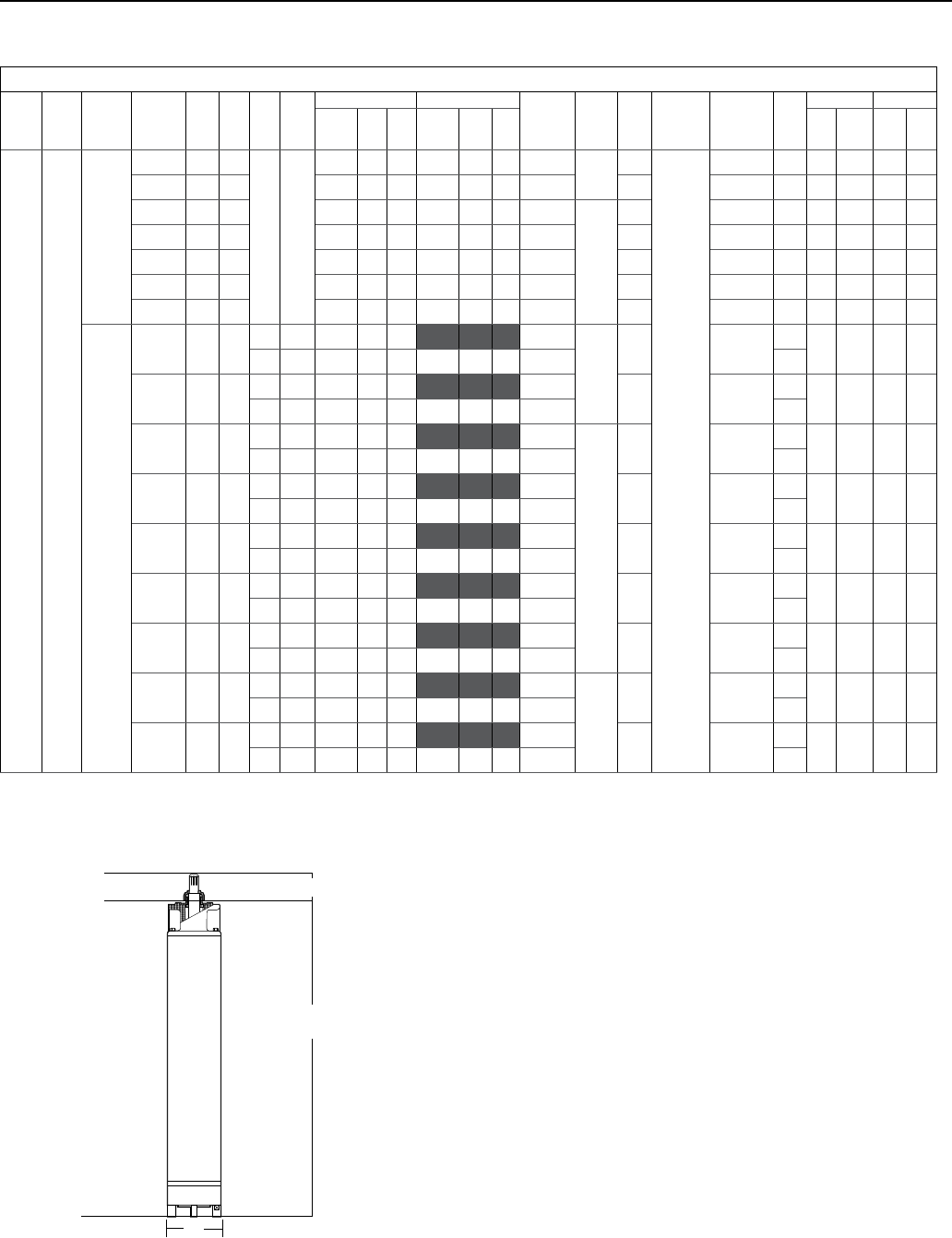
6.4 Motor Specifications
For lengths, refer to Ordering Information tables.
Dimensions are for estimating purposes only.
Nominal diameter 6"/152.4 mm
Effective diameter 5.43"/138 mm
Shaft extension length 2.87" / 73 mm
Ordering Information
MOTOR
TYPE PHASE NOTE
PENTEK
MODEL # HP KW HZ VOLTS
SERVICE FACTOR 1.00 SERVICE FACTOR 1.15 LOCKED
ROTOR
AMPS
THRUST
LOAD
KVA
CODE
INSULATION
CLASS
WINDING
RESISTANCE
(OHM) RPM
LENGTH WEIGHT
AMPS
EFF.
%
P.F.
%AMPS
EFF.
%
P.F.
%IN MM LBS KG
6” Three
Motors
are 60 Hz
only
6PM2-5-2 5 4
60 230
15 .2 75 83 16.4 77 85 102.1 1763 K
F
0.7873 3460 22.7 577 90 41
6PM2-7-2 7-1/2 6 21.2 79 85 23.2 79 86 146.4 J 0.5389 3460 24.9 632 102 46
6PM2-10-2 10 8 30.8 77 81 33.0 78 83 187.6
3485
J 0.3964 3440 29.2 741.5 116 53
6PM2-15-2 15 11 43.2 78 84 47.0 78 86 281.8 J 0.2782 3450 31.8 807.5 121 55
6MP2-20-2 20 15 57.4 79 85 63.0 79 87 394.5 J 0.2101 3450 35.1 892.5 147 67
6PM2-25-2 25 19 69 81 86 76.0 80 88 480.2 J 0.1605 3450 38.0 964.5 165 75
6PM2-30-2 30 22 76.6 84 88 85.0 84 89 614.2 K 0.1445 3500 41.8 1,060.5 190 86
Motors are
dual rated
50 Hz &
60 Hz
6PM2-5-4 5 4 50 380 8.9 75 87 45.6
1763
K 2.9674 2820 22.7 577 90 41
60 460 10.6 75 83 8.2 77 85 51.1 3460
6PM2-7-4 7-1/2 6 50 380 12.5 79 87 66.8 J 1.9828 2820 24.9 632 102 46
60 460 15.4 79 85 11.6 79 86 73.2 3460
6PM2-10-4 10 8 50 380 17.8 78 85 85.6
3485
J 1.4648 2800 29.2 741.5 116 53
60 460 15.4 77 81 16.5 78 83 93.8 3440
6PM2-15-4 15 11 50 380 25.6 77 87 127 J 0.9916 2810 31.8 807.5 131 55
60 460 21.6 78 84 23.5 78 86 140.9 3450
6PM2-20-4 20 15 50 380 34 78 89 170.2 J 0.7192 2810 35.1 892.5 147 67
60 460 28.5 79 85 31.5 79 87 197.3 3450
6MP2-25-4 25 19 50 380 41 79 89 219 J 0.5640 2820 38.0 964.5 165 75
60 460 34.5 81 86 38.0 80 88 240.1 3450
6PM2-30-4 30 22 50 380 46 83 90 276.8 K 0.5036 2880 41.8 1060.5 190 86
60 460 38 84 88 42.5 84 89 307.1 3500
6PM2-40-4 40 30 50 380 62.5 83 90 393.1
6182
K 0.3958 2860 47.1 1197 209 95
60 460 52.7 84 88 58.0 84 89 439.7 3490
6PM2-50-4 50 37 50 380 77.6 83 90 449.8 K .3295 2840 49.9 1267 292 132
60 460 64.3 85 87 70.8 85 89 500.5 3480
L
L1
D
6.5 Motor Dimensions
29
SECTION 6: Pentek® 6” Submersible Motors
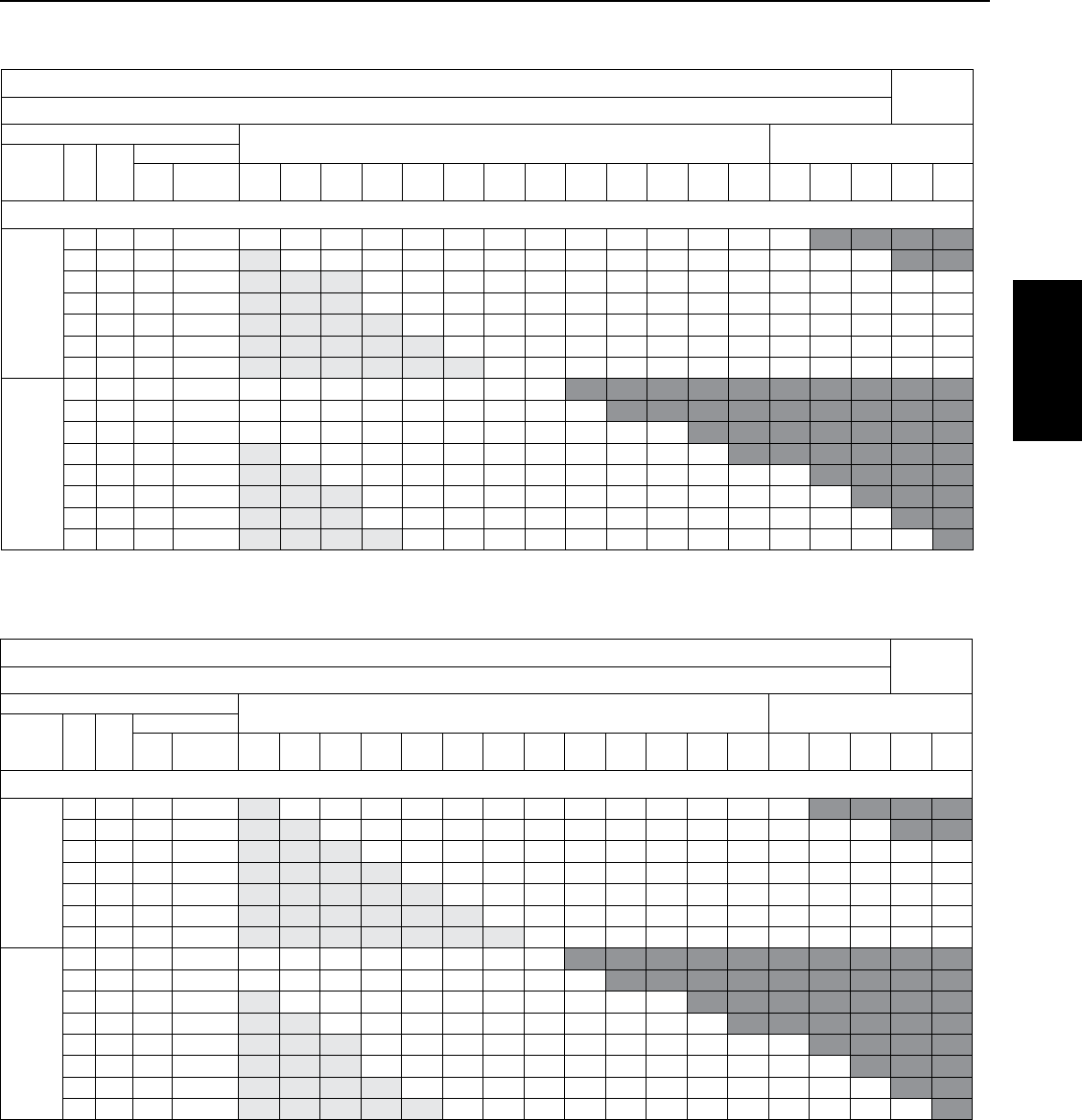
6.6 Motor Fuse Sizing and Cable Selection
CABLE SELECTION 60˚
COPPER CABLE SIZE - From Main Breaker Panel to Motor (in feet)
MOTOR
AWG MCM
VOLTS /
HZ HP KW
FUSE
STD
Dual
Element
14 12 10 864321000 000 0000 250 300 350 400 500
THREE PHASE
230 V
60 Hz
5 3.7 45 25 154 245 391 620 965 1538 1933 2442 3076 3883 4899 6184 7791 9198
7.5 5.5 60 40 - 174 277 438 682 1087 1367 1726 2174 2745 3463 4372 5508 6502 7806 9124
10 7.5 90 50 - - - 308 479 764 961 1213 1529 1930 2434 3073 3872 4571 5488 6415 7334 9125
15 11 125 80 - - - 216 337 537 675 852 1073 1355 1709 2158 2719 3210 3853 4504 5149 6407
20 15 175 110 - - - - 251 400 503 636 801 1011 1275 1610 2028 2394 2874 3360 3842 4780
25 18.5 225 125 - - - - - 332 417 527 664 838 1057 1334 1681 1985 2383 2785 3184 3962
30 22 250 125 - - - - - - 373 471 593 749 945 1193 1503 1775 2130 2490 2847 3543
460 V
60 Hz
or
380 V
50 Hz
5 3.7 20 10 617 982 1566 2480 3859 6152 7734 9767
7.5 5.5 30 20 436 694 1107 1753 2728 4349 5467 6904 8698
10 7.5 45 25 307 488 778 1233 1918 3057 3844 4854 6115 7719 9738
15 11 70 40 - 343 546 865 1347 2147 2699 3408 4293 5419 6837 8631
20 15 90 50 - - 408 646 1005 1601 2013 2543 3203 4043 5101 6439 8113 9578
25 18.5 110 60 - - - 535 833 1328 1669 2108 2655 3351 4228 5338 6725 7939 9531
30 22 125 70 - - - 479 745 1187 1492 1884 2374 2997 3781 4773 6013 7099 8522 9961
40 30 150 100 - - - - 546 870 1093 1381 1740 2196 2770 3497 4406 5202 6244 7299 8345
Lengths only meet the US National Electrical Code ampacity requirements for individual conductors rated 60° C in free air or water, NOT in magnetic enclosures, conduit or direct buried. Refer
to NEC Table 310.15(B)(17) for more information.
CABLE SELECTION 75° C
COPPER CABLE SIZE - From Main Breaker Panel to Motor (in feet)
MOTOR
AWG MCM
VOLTS /
HZ HP KW
FUSE
STD
Dual
Element
14 12 10 864321000 000 0000 250 300 350 400 500
THREE PHASE
230 V
60 Hz
5 3.7 45 25 - 245 391 620 965 1538 1933 2442 3076 3883 4899 6184 7791 9198
7.5 5.5 60 40 - - 277 438 682 1087 1367 1726 2174 2745 3463 4372 5508 6502 7806 9124
10 7.5 90 50 - - - 308 479 764 961 1213 1529 1930 2434 3073 3872 4571 5488 6415 7334 9125
15 11 125 80 - - - - 337 537 675 852 1073 1355 1709 2158 2719 3210 3853 4504 5149 6407
20 15 175 110 - - - - - 400 503 636 801 1011 1275 1610 2028 2394 2874 3360 3842 4780
25 18.5 225 125 - - - - - - 417 527 664 838 1057 1334 1681 1985 2383 2785 3184 3962
30 22 250 125 - - - - - - - 471 593 749 945 1193 1503 1775 2130 2490 2847 3543
460 V
60 Hz
or
380 V
50 Hz
5 3.7 20 10 617 982 1566 2480 3859 6152 7734 9767
7.5 5.5 30 20 436 694 1107 1753 2728 4349 5467 6904 8698
10 7.5 45 25 - 488 778 1233 1918 3057 3844 4854 6115 7719 9738
15 11 70 40 - - 546 865 1347 2147 2699 3408 4293 5419 6837 8631
20 15 90 50 - - - 646 1005 1601 2013 2543 3203 4043 5101 6439 8113 9578
25 18.5 110 60 - - - 535 833 1328 1669 2108 2655 3351 4228 5338 6725 7939 9531
30 22 125 70 - - - - 745 1187 1492 1884 2374 2997 3781 4773 6013 7099 8522 9961
40 30 150 100 - - - - - 870 1093 1381 1740 2196 2770 3497 4406 5202 6244 7299 8345
Lengths only meet the US National Electrical Code ampacity requirements for individual conductors rated 75° C in free air or water, NOT in magnetic enclosures, conduit or direct buried. Refer
to NEC Table 310.15(B)(17) for more information.
Pentek 6” Motors
30
SECTION 6: Pentek® 6” Submersible Motors
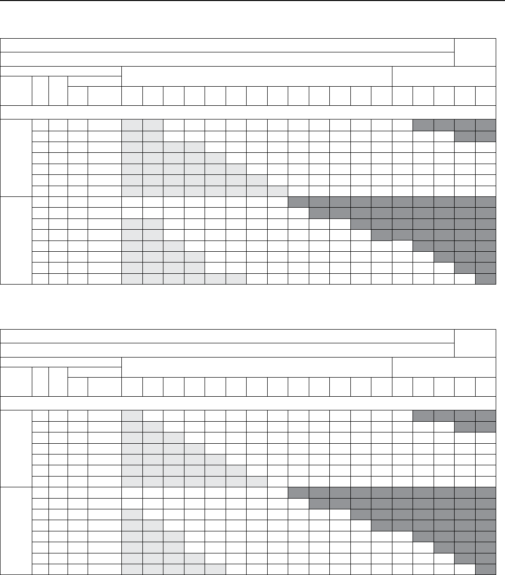
6.6 Motor Fuse Sizing and Cable Selection
CABLE SELECTION 75° C
COPPER CABLE SIZE - From Main Breaker Panel to Motor (in feet)
MOTOR
AWG MCM
VOLTS HP KW
FUSE
STD
Dual
Element
14 12 10 864321000 000 0000 250 300 350 400 500
THREE PHASE
230 V
60 Hz
5 3.7 45 25 - 245 391 620 965 1538 1933 2442 3076 3883 4899 6184 7791 9198
7.5 5.5 60 40 - - 277 438 682 1087 1367 1726 2174 2745 3463 4372 5508 6502 7806 9124
10 7.5 90 50 - - - 308 479 764 961 1213 1529 1930 2434 3073 3872 4571 5488 6415 7334 9125
15 11 125 80 - - - - 337 537 675 852 1073 1355 1709 2158 2719 3210 3853 4504 5149 6407
20 15 175 110 - - - - - 400 503 636 801 1011 1275 1610 2028 2394 2874 3360 3842 4780
25 18.5 225 125 - - - - - - 417 527 664 838 1057 1334 1681 1985 2383 2785 3184 3962
30 22 250 125 - - - - - - - 471 593 749 945 1193 1503 1775 2130 2490 2847 3543
460 V
60 Hz
or
380 V
50 H
5 3.7 20 10 617 982 1566 2480 3859 6152 7734 9767
7.5 5.5 30 20 436 694 1107 1753 2728 4349 5467 6904 8698
10 7.5 45 25 - 488 778 1233 1918 3057 3844 4854 6115 7719 9738
15 11 70 40 - - 546 865 1347 2147 2699 3408 4293 5419 6837 8631
20 15 90 50 - - - 646 1005 1601 2013 2543 3203 4043 5101 6439 8113 9578
25 18.5 110 60 - - - 535 833 1328 1669 2108 2655 3351 4228 5338 6725 7939 9531
30 22 125 70 - - - - 745 1187 1492 1884 2374 2997 3781 4773 6013 7099 8522 9961
40 30 150 100 - - - - - 870 1093 1381 1740 2196 2770 3497 4406 5202 6244 7299 8345
Lengths meet the US National Electrical Code ampacity requirements for either individual conductors or jacketed rated 75° C cable and can be in conduit or direct buried. Flat molded and web/
ribbon cable are considered jacketed cable. Refer to NEC Table 310.15(B)(16) for more information.
CABLE SELECTION 60° C
COPPER CABLE SIZE - From Main Breaker Panel to Motor (in feet)
MOTOR
AWG MCM
VOLTS HP KW
FUSE
STD
Dual
Element
14 12 10 864321000 000 0000 250 300 350 400 500
THREE PHASE
230 V
60 Hz
5 3.7 45 25 - - 391 620 965 1538 1933 2442 3076 3883 4899 6184 7791 9198
7.5 5.5 60 40 - - 277 438 682 1087 1367 1726 2174 2745 3463 4372 5508 6502 7806 9124
10 7.5 90 50 - - - - 479 764 961 1213 1529 1930 2434 3073 3872 4571 5488 6415 7334 9125
15 11 125 80 - - - - - 537 675 852 1073 1355 1709 2158 2719 3210 3853 4504 5149 6407
20 15 175 110 - - - - - - 503 636 801 1011 1275 1610 2028 2394 2874 3360 3842 4780
25 18.5 225 125 - - - - - - - 527 664 838 1057 1334 1681 1985 2383 2785 3184 3962
30 22 250 125 - - - - - - - - 593 749 945 1193 1503 1775 2130 2490 2847 3543
460 V
60 Hz
or
380 V
50 Hz
5 3.7 20 10 617 982 1566 2480 3859 6152 7734 9767
7.5 5.5 30 20 436 694 1107 1753 2728 4349 5467 6904 8698
10 7.5 45 25 - - 778 1233 1918 3057 3844 4854 6115 7719 9738
15 11 70 40 - - 546 865 1347 2147 2699 3408 4293 5419 6837 8631
20 15 90 50 - - - 646 1005 1601 2013 2543 3203 4043 5101 6439 8113 9578
25 18.5 110 60 - - - - 833 1328 1669 2108 2655 3351 4228 5338 6725 7939 9531
30 22 125 70 - - - - 745 1187 1492 1884 2374 2997 3781 4773 6013 7099 8522 9961
40 30 150 100 - - - - - - 1093 1381 1740 2196 2770 3497 4406 5202 6244 7299 8345
Lengths meet the US National Electrical Code ampacity requirements for either individual conductors or jacketed rated 60° C cable and can be in conduit or direct buried. Flat molded and web/
ribbon cable are considered jacketed cable. Refer to NEC Table 310.15(B)(16) for more information.
* = motors are 8” diameter

31
NEMA SIZE MAX HP OF
CONTACTOR DISCONNECT A MAX TOTAL A
OF PPX PANEL O/L CURRENT
RANGE CATALOG
NUMBER
DIMENSIONS
H x W x D WEIGHT
(LBS.)
1 7.5 30 13.5 6.5 – 13.5 PPX-1A-13-30R 34 x 21 x 7 85
27
13 – 27
PPX-1A-27-30R
34 x 21 x 7
85
2 10 60 50 25 – 50 PPX-2A-50-60R 34 x 21 x 7 90
3 25 100 70 35 – 70 PPX-3A-70-100R 47.5 x 25 x 9 195
100 65 – 135 PPX-3A-135-100R 47.5 x 25 x 9 195
4 40 200 135 65 – 135 PPX-4A-135-200R 47.5 x 25 x 9 195
208 VAC
Note: For HPs with multiple part numbers, use motor amperage to select a panel.
Note: For HPs with multiple part numbers, use motor amperage to select a panel.
NEMA SIZE MAX HP OF
CONTACTOR DISCONNECT A MAX TOTAL A
OF PPX PANEL O/L CURRENT
RANGE CATALOG
NUMBER
DIMENSIONS
H x W x D WEIGHT
(LBS.)
1 7.5 30 13.5 6.5 – 13.5 PPX-1B-13-30R 34 x 21 x 7 85
27
13 – 27
PPX-1B-27-30R
34 x 21 x 7
85
2 15 60 50 25 – 50 PPX-2B-50-60R 34 x 21 x 7 90
3 30 100 70 35 – 70 PPX-3B-70-100R 47.5 x 25 x 9 195
100 65 – 135 PPX-3B-135-100R 47.5 x 25 x 9 195
230-240 VAC
Note: For HPs with multiple part numbers, use motor amperage to select a panel.
NEMA SIZE MAX HP OF
CONTACTOR DISCONNECT A MAX TOTAL A
OF PPX PANEL O/L CURRENT
RANGE CATALOG
NUMBER
DIMENSIONS
H x W x D WEIGHT
(LBS.)
1 10 30 13.5 6.5 – 13.5 PPX-1C-13-30R 34 x 21 x 7 85
27 13 – 27 PPX-1C-27-30R 34 x 21 x 7 85
2 25 60 50 25 – 50 PPX-2C-50-60R 34 x 21 x 7 90
3 50 100 70 35 – 70 PPX-3C-70-100R 47.5 x 25 x 9 195
100 65 – 135 PPX-3C-135-200R 47.5 x 25 x 9 195
4 100 200 135 65 – 135 PPX-4C-135-200R 47.5 x 25 x 9 195
5 200 400 270 130 – 270 PPX-5C-270-400R 52 x 22 x 10 285
460-480 VAC
Note: For HPs with multiple part numbers, use motor amperage to select a panel.
NEMA SIZE MAX HP OF
CONTACTOR DISCONNECT A MAX TOTAL A
OF PPX PANEL O/L CURRENT
RANGE CATALOG
NUMBER
DIMENSIONS
H x W x D WEIGHT
(LBS.)
1 10 30 13.5 6.5 – 13.5 PPX-1D-13-30R 34 x 21 x 7 85
27 13 – 27 PPX-1D-27-30R 34 x 21 x 7 85
2 25 60 50 25 – 50 PPX-2D-50-60R 34 x 21 x 7 90
3 50 100 70 35 – 70 PPX-3D-70-100R 47.5 x 25 x 9 195
100 65 – 135 PPX-3D-135-100R 47.5 x 25 x 9 195
4 100 200 135 65 – 135 PPX-4D-135-200R 47.5 x 25 x 9 195
5 200 400 270 130 – 270 PPX-5D-270-400R 52 x 22 x 10 285
575-600 VAC
SECTION 6: Pentek® 6” Submersible Motors
6.7 Overload Protection
Pentek 6” Motors
32
SECTION 6: Pentek® 6” Submersible Motors
6.7 Overload Protection
Submersible motors must have Class 10 overload protection that will disconnect the power within 10 seconds in the
case of a locked rotor. To accomplish this, fixed-heater overloads are used. Refer to Section 10 for appropriate heaters.
The chart is based upon total line amps. Divide the motor amps by 1.732 when using a 6-lead motor with a Y-Delta
Starter. Notice: General Electric overload heaters are only usable with general electric overload relays. Do not adjust
relays to exceed nameplate amps.
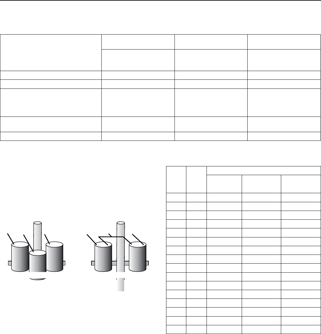
6.8 Motor Cooling
Pentek 6” motors are designed for minimum water flow of 0.5 ft. /sec. past the motor. Maximum water temperature is
95° F (35° C).
6” MOTORS: MINIMUM COOLING WATER FLOW
I.D of casing Flow (GPM) required
6 9
7 25
8 40
10 85
12 140
14 200
16 280
If the flow is less than specified, a flow-inducer sleeve can be installed. This will act like a smaller casing size, and
force flow around the motor to aid cooling. Always use a flow-inducer sleeve when the pump is in open water.
6.9 Head Loss In Casing
Use the chart below to account for the head loss around the pump.
6.10 Starting Frequency
To extend the life of the pump motor and control, limit the number of starts
to 100 per 24 hours. If higher starting frequencies are necessary, consult
your factory. To prevent overheating, run motor for a minimum of two
minutes. For starting frequency, refer to section 5.10.
Head loss in feet for flow past motor
6” MOTORS CASING INSIDE DIAMETER
6”
7”
8”
GPM
100
1.7
150 3.7
200 6.3 0.5
250 9.6 0.8
300 13.6 1.2 0.2
400 23.7 2.0 0.4
500 3.1 0.7
600 4.4 1.0

33
Problem Possible Causes Solution
Motor does not start, but does not
blow fuses or trip circuit breaker
Defective fuses or circuit breakers
Loose or corroded terminals
Damaged or defective connections
No incoming power
Replace fuses or circuit breakers.
Clean and tighten connections and
motor lead terminals.
Repair or replace connections.
Contact power company.
Motor starts, but fuses blow or
circuit breakers trip
Wrong voltage
Incorrect fuses or relay
Incorrect connections
Locked rotor or pump
Insufficient insulation on motor
cables
Make sure that nameplate rated
voltage matches nominal power
supply, and that actual supply voltage
is within ±10% of nameplate voltage.
Install correct fuses or relay.
Re-connect motor wires correctly.
Make sure that motor is at least 10ft
above bottom of well, check well for
sand.
Install new motor cables; recheck
resistance with Megohmeter.
Motor starts and runs, then blows
fuse or trips circuit breaker
Incoming voltage more than 10% high
or low sand in well
Confirm high or low voltage in motor
cable, consult power company.
Pull the pump and clean the well.
Motor does not start, but fuse
blows or circuit breaker trips
Locked rotor or pump Check for sand in well.
Make sure that motor is at least 10ft
above the bottom of the well.
Pull pump and check for mechanical
obstruction in the pump and for free
rotation of the motor.
SECTION 6: Pentek® 6” Submersible Motors
6.11 Troubleshooting
Pentek 6” Motors

34
SECTION 7: Hitachi® 6” and Larger Submersible Motors
7.1 Motor Inspection
The following conditions are stated to provide the owner
with a list of criteria for maximum motor life and to
assure motor warranty.
1. Maximum water temperature:
• A) 35°C (95°F): 6” (5~40HP) motors.
• B) 25°C (77°F): 6” (50,60HP), 8’’, 10”, 12’’ and 14”
motors
2. PH content of the water between: 6.5 -8
3. Maximum chlorine content: 500 PPM
• Maximum Sulfuric acid iron content: 15 PPM
• Maximum Fluorine content: 0.8 PPM
• Maximum Electric conductivity: 118 μMHO/INCH
4. Maximum sand content: 50 PPM
5. Proper approved three phase overload protection.
See Table 13.
6. Proper fusing for motor circuit protection.
See Table C.
7. Proper line voltage during running conditions:
60Hz: 460V, 230V ±10%
50Hz: 380V ±10%
at motor lead terminal. (Voltage drop of cable should
be considered by user.)
Combination of voltage and frequency variation:
±10% (sum of absolute values of voltage and
frequency)
Current unbalance between legs should not exceed
5% of the average.
8. Proper sizing of motor (current, thrust, voltage, etc.)
and a 10 feet clearance from the bottom of the well
are required.
9. In the case of horizontal installation, the motor is to
be rigidly aligned with the pump and firmly mounted
to prevent any load on the shaft and bearings and to
avoid any damaging vibrations to the motor.
10. The motor must always be immersed in water so that
a flow velocity of cooling water at a rate of 0.5 feet
per second flows past any and all parts of the motor.
The motor will not operate in mud or sand.
11. The power cables shall be sized large enough so
that at rated current there will be less than a 5%
voltage drop. See Table C. Cables must be waterproof
submersible type.
12. For 3ø motor a balanced and properly sized
transformer bank shall be provided. Improper
electrical supply (for example, phase converter.
V-connection transformer, etc.) or connections will
void the warranty
13. Single-phase protection is recommended for
protection of the installation. Any failure due to single
phasing of the incoming voltage causing the motor to
fail will void the warranty.
14. Surge suppressors are recommended in the interest
of protecting the control panel, as well a.s the
insulation system of the motor. Any motor failure
due to lightning or other Acts of God will void the
warranty.
15. Provide waterproof insulation splices between all
lead wires and well cables.
16. In the event that a reduced voltage starter is used to
start the motor, the following should be verified:
• Correct quick trip, class 10 or better, ambient
compensated overloads are incorporated.
• Proper short circuit protection is utilized.
• The torque required by the motor and pump package
is attainable by this type starter.
• The lead arrangement of the motor is acceptable with
the proposed starter load connections.
• Verify that if any time delay relays are used in
switching contactors in and out, that the time settings
do not exceed 2 seconds; this could damage the
motor.
• lf a manual auto transformer starter is used, voltage
should be minimum 60% of rated voltage, and
switched to “Run”condition within 2 seconds. Double
check Table B and C for correct protection.
17. Single-Phase Motors (5-15HP)
Proper connections and correct capacitors and
relays are necessary for single-phase motor starting
and running. Connection diagram: Sec Fig. 1.
Performance and recommendable capacitors: See
Table D.
7.2 Testing
1. Do not use lead wires to pull, lift or handle the motor.
The lead wires should be protected during storage,
handling, moving and installation of the motor. 2)
2. Inspect the motor to determine that it is the correct
HP, voltage and size for the job and that there is no
shipping damage.
3. The factory-installed water in the motor is supplied
with anti-freeze capable of temperatures to
0°C(-22°F). Do not install, transport or store below
these temperatures. If storage is necessary below
these temperatures, drain the water from the motor.
4. After long periods of idleness and on all new
installations, check the electrical resistance and
megger the motor with lead wires connected: see
table A. Prior to installation, the motor should have
an insulation value of at least 50 megohms. After
installation, motor and power cable should have a
minimum insulation value of 1 megohm. If minimum
values are not obtained, contact factory.
Hitachi® is a registered trademark of Hitachi Industrial Equipment Systems Co., Ltd.

35
SECTION 7: Hitachi® 6” and Larger Submersible Motors
7.2 Testing
5. Verify motor is filled with clean water before
installing. The warranty is void if this is not done.
Also check the tightness of all water filling and drain
plugs, mounting bolts and cable connections.
6. Do not hammer the shaft, coupling or slinger since
this may damage the thrust bearing. Check the
rotation of the motor by hand to insure that it turns
freely.
7. Do not drop the bottom end of the motor in the dirt or
mud since this may plug up the diaphragm opening.
8. If motor is to be installed horizontal, make sure that
the lead wires are at the 12 o’clock position when
facing the motor shaft (in horizontal position).
NOTE:
There are no bearings that need oil or grease. The motor,
being inaccessible, should be monitored through its
electrical connections.
• A) Measure and record operating current and voltage.
• B) Measure and record the motor insulation
resistance. Any resistance of less than 50 megohm
(5,000,000) for a new motor should be evaluated or
checked further by a qualified service shop.
• Lightning arrestors and/or surge capacitors will help
prevent damage to the control box, cables, and motor.
• Single-phase protection will help in preventing motor
failure due to adverse incoming primary power.
• Based on the values obtained in A and B above and
the output flow rates and pressures of the pump,
a complete picture of total performance can be
obtained. This can be used to determine any pump
and motor maintenance and overhauling which might
be required.
• If the motor is to be stored, protect the unit from
freezing by storing in an area with a temperature
higher than -30°C (-22° F).
7.3 Storage and Drain Fill Instructions
1. After energizing the motor, check the flow and
pressure of the pump to make sure that the motor
is rotating in the correct direction. To correct a
wrong rotation, switch any two of the three cable
connections. (Three-phase motor only)
2. When starting the pump for the first time, inspect
the water for sand. If sand appears, then continue
to pump till the water clears up; otherwise, sand
will accumulate in the pump stages and will bind or
freeze the moving parts if water is allowed to flow
back down the well.
3. During testing or checking rotation (such as
“humping” or “inching”) the number of “starts”
should be limited to 3, followed by a full 15 minute
cooling-off period before any additional “starts’’
are attempted. Depending on the depth of the well
and/or method of checking, these rotational checks
or ‘’starts’’ may actually be full-fledged starts. If
this is the case, then a full cooling-off period of 15
minutes is required between this type of start.
4. For automatic (pilot device) operation, the motor
should be allowed to cool for 15 minutes between
starts.
5. Input voltage, current and insulation resistance
values should be recorded throughout the life of
the installation and should be used as a from of
preventive maintenance.
Hitachi 6” and
Larger Motors
Hitachi® is a registered trademark of Hitachi Industrial Equipment Systems Co., Ltd.

36
SECTION 7: Hitachi® 6” and Larger Submersible Motors
7.4 Motor Specifications
TABLE A. RESISTANCE DATA
Single Phase 2 Pole 230V/60Hz
Motor Size and Type HP Resistance (Ω)
R – Y B – Y R – B
6”, C 5 2.172 0.512 2.627
“ 7.5 1.401 0.400 1.774
“ 10 1.052 0.316 1.310
“ 15 0.678 0.230 0.850
Three Phase 2 Pole
Motor Size and Type HP Volt Resistance (Ω)
6”, C 5 230 .806
“ 5 460 3.050
“ 7.5 230 0.651
“ 7.5 460 2.430
“ 10 230 0.448
“ 10 460 1.619
“ 15 230 0.312
“ 15 460 1.074
“ 20 230 0.258
“ 20 460 0.861
“ 25 230 0.210
“ 25 460 0.666
“ 30 230 0.166
“ 30 460 0.554
“ 40 460 0.446
“ 50 “ 0.388
“ 60 “ 0.388
8”,W 40 “ 0.372
“ 50 “ 0.331
“ 60 “ 0.278
“ 75 “ 0.218
“ 100 “ 0.164
“ 125 “ 0.132
“ 150 “ 0.115
10”, W 175 “ 0.121
“ 200 “ 0.0929
“ 250 “ 0.0776
12”, W 300 “ 0.0386
Three Phase 4 Pole
Motor Size and Type HP Volt Resistance (Ω)
8”, W 7.5 230 .564
“ 7.5 460 2.178
“ 10 230 0.564
“ 10 460 2.178
“ 15 230 0.399
“ 15 460 1.519
“ 20 230 0.399
“ 20 460 1.519
“ 25 230 0.242
“ 25 460 0.888
“ 30 230 0.242
“ 30 460 0.888
10”, W 40 230 0.408
“ 50 460 0.408
“ 60 460 0.288
“ 75 “ 0.257
“ 100 “ 0.171
125 “ 0.171
12“, W 150 “ 0.138
“ 175 “ 0.119
“ 200 “ 0.0826
14“, W 250 “ 0.0552
“ 300 “ 0.0517
Values are for normal temp. 68° (20°) with motor lead wires.
LEAD WIRE COLOR
R: Red
Y: Yellow
B: Black
G: Green (6” only)
MOTOR TYPE
C: CANNED
W: WATER TYPE
Hitachi® is a registered trademark of Hitachi Industrial Equipment Systems Co., Ltd.
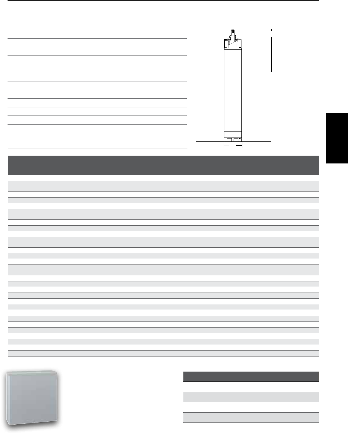
37
SECTION 7: Hitachi® 6” and Larger Submersible Motors
7.4 Motor Specifications
PARTS MATERIALS
Motor Sleeve Stainless steel construction
Castings Baked epoxy-coated gray iron
Fasteners Stainless steel
Shaft NEMA splined stainless steel
Flange NEMA standard type
Rotor Double epoxy-coated
Thrust Bearings Kingsbury-type 420 stainless steel
Mechanical Seal Nitrile rubber (NBR), grease packed
Diaphragm Nitrile rubber
Sand Cap Polyurethane
Sand Slinger Stainless steel
Lead Wire (or Cable) Double-insulated, heat and water-resistant,
167°F/75°C, 600V
Type 1 NEMA Enclosure
In-Panel Circuit Breaker
Magnetic Contactor
Terminal Blocks for External Controls
UL Recognized
HP
KW
PH
VOLTS
CATALOG NUMBER
5 3.7 1 230 HIT-5CBD
7.5 5.5 1 230 HIT-7.5CBD
10 7.5 1 230 HIT-10CBD
15 11 1 230 HIT-15CBD
DIAMETER HP KW VOLTS PH HZ
CATALOG
NUMBER
SERVICE
FACTOR
WINGING
RESISTANCE
(OHMS)
RATED
INPUT
AMPS
SERVICE
FACTOR
INPUT AMPS
SHAFT
EXTENSION
(L1)
LENGTH
(L2)
DIAMETER
(D)
THRUST
CAPACITY WEIGHT
6 5 3.7 200 3 60 6HIT2-5-8 1.15 17.5 19.5 2.87" 22.95" 5.5" 3,500 95
6 5 3.7 230 1 60 6HIT2-5-1 1.15 R-Y, B-Y, R-B, 2.172,
0.512, 2.627 24 27.5 2.87" 26.97" 5.5" 3,500 110
6 5 3.7 230 3 60 6HIT2-5-2 1.15 0.806 15 17 2.87" 22.95" 5.5" 3,500 95
6 5 3.7 460 3 60 6HIT2-5-4 1.15 3.05 7.5 8.5 2.87" 22.95" 5.5" 3,500 95
6 7.5 5.5 200 3 60 6HIT2-7-8 1.15 25.4 28.5 2.87" 24.80" 5.5" 3,500 99
6 7.5 5.5 230 1 60 6HIT2-7-1 1.15 R-Y, B-Y, R-B, 1.401,
0.400, 1.774 36 41 2.87" 29.92" 5.5" 3,500 128
6 7.5 5.5 230 3 60 6HIT2-7-2 1.15 0.651 22 26 2.87" 24.80" 5.5" 3,500 99
6 7.5 5.5 460 3 60 6HIT2-7-4 1.15 2.43 11 13 2.87" 24.80" 5.5" 3,500 99
6 10 7.5 200 3 60 6HIT2-10-8 1.15 33.3 37.2 2.87" 26.97" 5.5" 3,500 110
6 10 7.5 230 1 60 6HIT2-10-1 1.15 R-Y, B-Y, R-B, 1.052,
0.316, 1.310 50 58 2.87" 29.92" 5.5" 3,500 128
6 10 7.5 230 3 60 6HIT2-10-2 1.15 0.448 29 33 2.87" 26.97" 5.5" 3,500 110
6 10 7.5 460 3 60 6HIT2-10-4 1.15 1.619 14.5 16.5 2.87" 26.97" 5.5" 3,500 110
6 15 11 200 3 60 6HIT2-15-8 1.15 47.4 53.5 2.87" 29.92" 5.5" 3,500 128
6 15 11 230 1 60 6HIT2-15-1 1.15 R-Y, B-Y, R-B, 0.678,
0.230, 0.850 72 85 2.87" 33.46" 5.5" 3,500 148
6 15 11 230 3 60 6HIT2-15-2 1.15 0.312 42 46 2.87" 29.92" 5.5" 3,500 128
6 15 11 460 3 60 6HIT2-15-4 1.15 1.074 21 23 2.87" 29.92" 5.5" 3,500 128
6 20 15 200 3 60 6HIT2-20-8 1.15 61.2 69.5 2.87" 31.5" 5.5" 3,500 137
6 20 15 230 3 60 6HIT2-20-2 1.15 0.258 54 60 2.87" 31.5" 5.5" 3,500 137
6 20 15 460 3 60 6HIT2-20-4 1.15 0.861 27 30 2.87" 31.5" 5.5" 3,500 137
6 25 18.5 200 3 60 6HIT2-25-8 1.15 77.3 87.5 2.87" 36.22" 5.5" 3,500 161
6 25 18.5 230 3 60 6HIT2-25-2 1.15 0.21 68 76 2.87" 36.22" 5.5" 3,500 161
6 25 18.5 460 3 60 6HIT2-25-4 1.15 0.666 34 38 2.87" 36.22" 5.5" 3,500 161
6 30 22 200 3 60 6HIT2-30-8 1.15 91.8 104 2.87" 38.19" 5.5" 3,500 176
6 30 22 230 3 60 6HIT2-30-2 1.15 0.166 82 94 2.87" 39.19" 5.5" 3,500 176
6 30 22 460 3 60 6HIT2-30-4 1.15 0.554 41 47 2.87" 38.19" 5.5" 3,500 176
6 40 30 460 3 60 6HIT2-40-4 1.15 0.358 56 61 2.87" 40.55" 5.5" 5,000 187
8 50 37 460 3 60 86HIT2-50-4* 1.15 0.331 65 73 2.87" 45.28" 7.52" 5,000 353
8 60 45 460 3 60 86HIT2-60-4* 1.15 0.278 80 90 2.87" 48.03" 7.52" 5,000 408
*Models are 8" motors with 6" pump connection.
L
L1
D
Hitachi Control Boxes
Materials of Construction Motor Dimensions
Hitachi 6” and
Larger Motors
Hitachi® is a registered trademark of Hitachi Industrial Equipment Systems Co., Ltd.
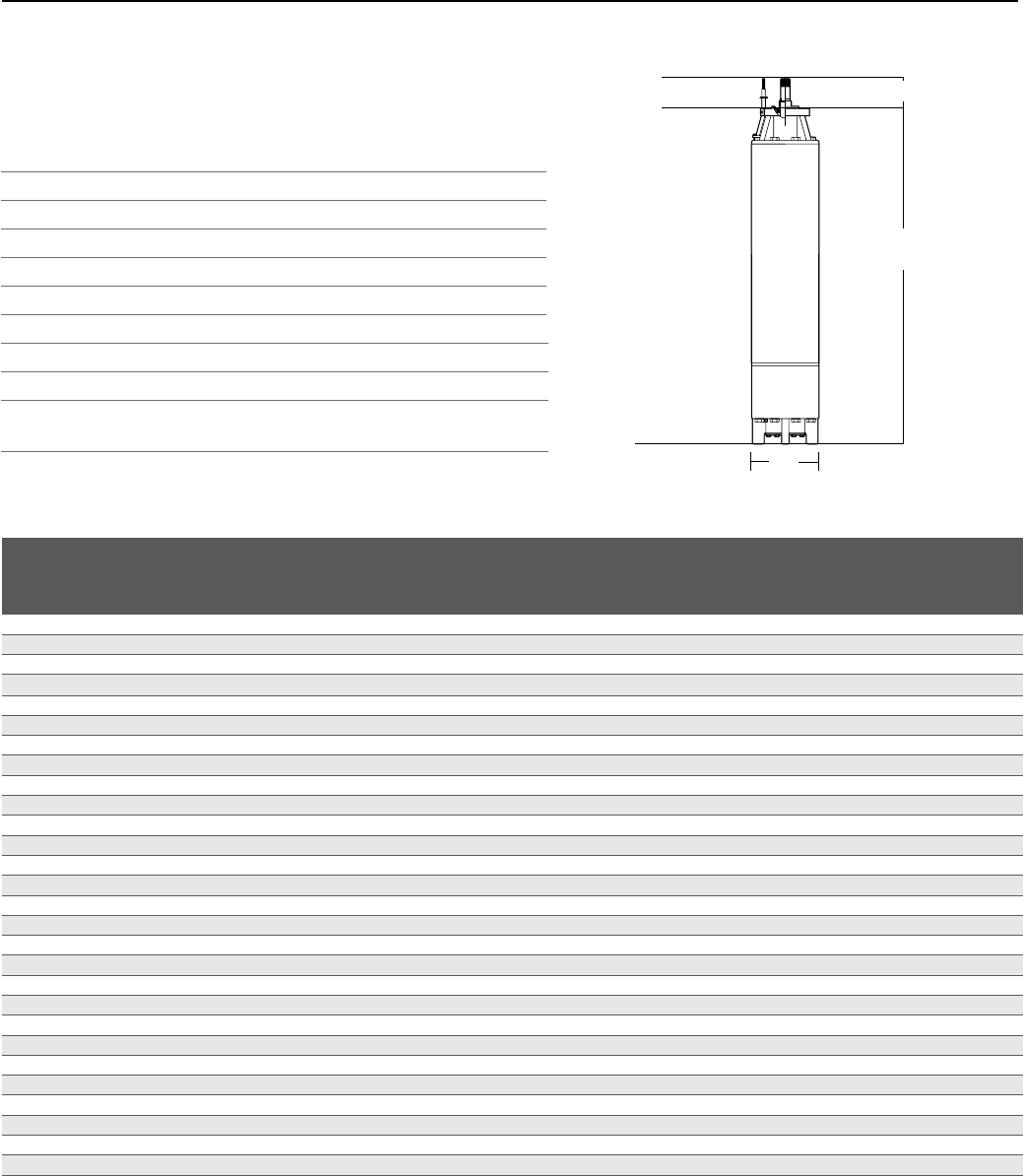
38
SECTION 7: Hitachi® 6” and Larger Submersible Motors
7.4 Motor Specifications
PARTS MATERIALS
Housing Baked epoxy-coated gray iron
Fasteners Stainless steel
Shaft Splined or keyed stainless steel
Rotor Double epoxy-coated
Thrust Bearings Kingsbury-type 420 stainless steel
Mechanical Seal Nitrile rubber (NBR), grease packed
Diaphragm Nitrile rubber
Sand Slinger Baked epoxy-coated gray iron
Lead Wire (or Cable) Double-insulated, heat and water-resistant,
167°F/75°C, 600V
MOTOR
DIAMETER HP KW VOLTS PH HZ RPM
CATALOG
NUMBER
LENGTH
(L)
SHAFT
EXTENSION
(L1)
DIAMETER
(D)
THRUST
CAPACITY WEIGHT
8* 50 37 460 3 60 3600 86HIT2-50-4 45.28 2.875 5.5 10,000 **5,000 157
8* 60 45 460 3 60 3600 86HIT2-60-4 48.03 2.875 5.5 10,000 **5,000 182
8 7.5 5.5 460 3 60 1800 8HIT4-7-4 32.4 4 7.52 10,000 298
8 10 7.5 460 3 60 1800 8HIT4-10-4 32.4 4 7.52 10,000 298
8 15 11 460 3 60 1800 8HIT4-15-4 41.34 4 7.52 10,000 320
8 20 15 460 3 60 1800 8HIT4-20-4 41.34 4 7.52 10,000 320
8 25 18.5 460 3 60 1800 8HIT4-25-4 44.09 4 7.52 10,000 342
8 30 22 460 3 60 1800 8HIT4-30-4 44.09 4 7.52 10,000 342
8 40 30 460 3 60 3600 8HIT2-40-4 44.09 4 7.52 10,000 320
8 50 37 460 3 60 3600 8HIT2-50-4 46.44 4 7.52 10,000 353
8 60 45 460 3 60 3600 8HIT2-60-4 49.19 4 7.52 10,000 408
8 75 55 460 3 60 3600 8HIT2-75-4 53.15 4 7.52 10,000 463
8 100 75 460 3 60 3600 8HIT2-100-4 53.8 4 7.52 10,000 518
8 125 90 460 3 60 3600 8HIT2-125-4 66.14 4 7.52 10,000 595
8 150 110 460 3 60 3600 8HIT2-150-4 70.08 4 7.52 10,000 661
10 40 30 460 3 60 1800 10HIT4-40-4 49.21 4 8.52 10,000 507
10 50 37 460 3 60 1800 10HIT4-50-4 49.21 4 8.52 10,000 507
10 60 45 460 3 60 1800 10HIT4-60-4 59.84 4 8.52 10,000 639
10 75 55 460 3 60 1800 10HIT4-75-4 59.84 4 8.52 10,000 639
10 100 75 460 3 60 1800 10HIT4-100-4 69.68 5 8.52 10,000 794
10 125 90 460 3 60 1800 10HIT4-125-4 69.68 5 8.52 10,000 794
10 200 150 460 3 60 3600 10HIT2-200-4 69.68 5 8.52 10,000 816
10 250 185 460 3 60 3600 10HIT2-250-4 79.53 5 8.52 10,000 948
12 150 110 460 3 60 1800 12HIT4-150-4 56.3 5 10.53 10,000 959
12 200 150 460 3 60 1800 12HIT4-200-4 68.11 5 10.53 10,000 1235
12 300 225 460 3 60 3600 12HIT2-300-4 78.75 5 10.53 10,000 1455
14 250 185 460 3 60 1800 14HIT4-250-4 68.31 5 12.6 10,000 1698
14 300 225 460 3 60 1800 14HIT4-300-4 76.18 5 12.6 10,000 1940
*Motor is 8" diameter, but constructed to operate with a 6" liquid end. ** 8" motors with 6" flange when using stainless steel bolts have
a thrust rating of 5,000 lbs. A thrust value of 10,000 lbs. can be
obtained using grade-8 heat-treated stainless steel bolts.
L
D
L1
Materials of Construction
Hitachi® is a registered trademark of Hitachi Industrial Equipment Systems Co., Ltd.
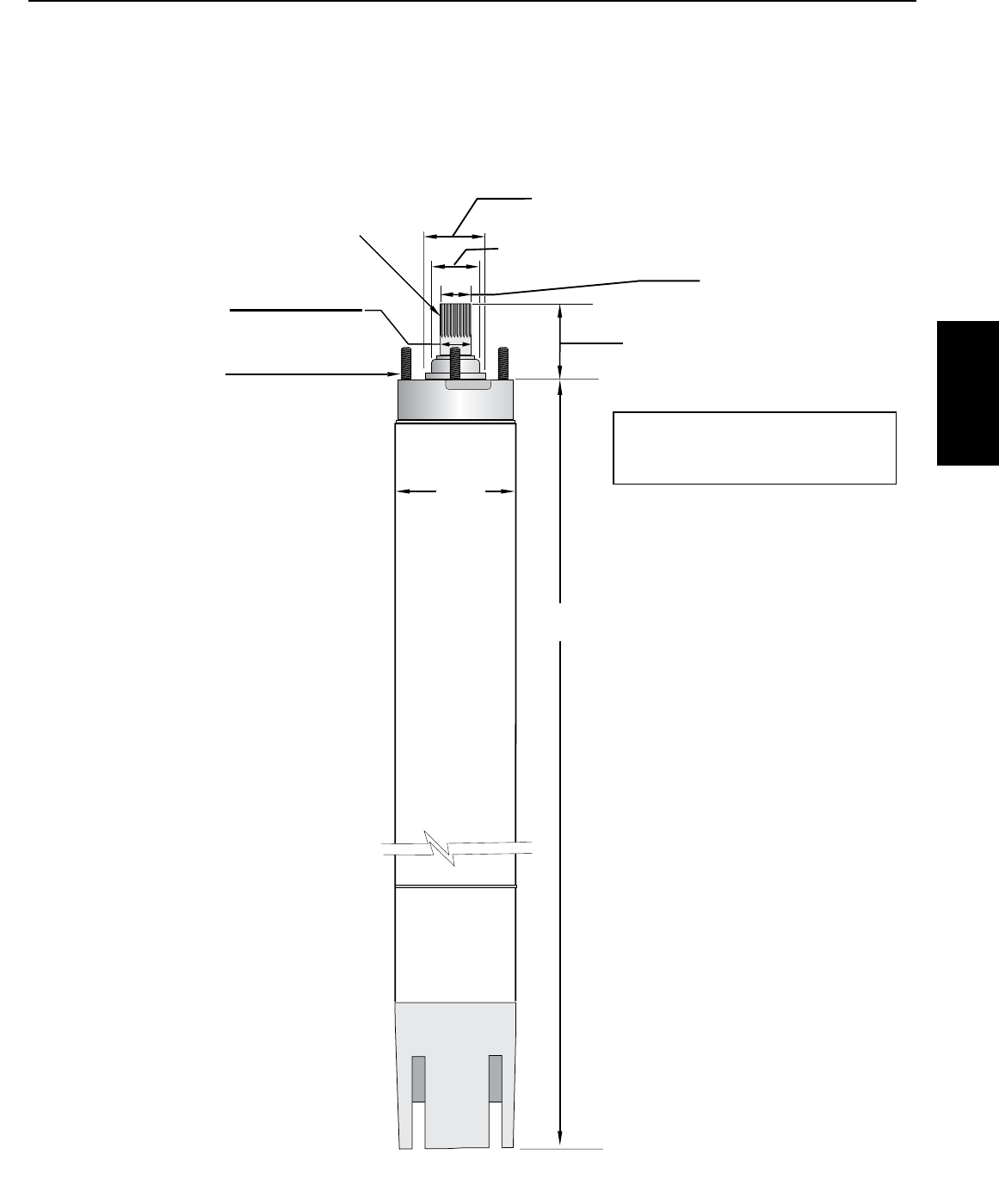
39
SECTION 7: Hitachi® 6” and Larger Submersible Motors
7.5 Motor Dimensions
Length
3.000 (76.2)
2.997 (76.12)
1.811 (45.99)
Spline Data
15 Teeth
16/32 Pitch
ANSI B92.1 Compliant
Min. 0.95 (24.13) Full Spline
2.875 (73.03)
2.860 (72.64)
0.987 (25.987)
0.982 (24.943)
5.51
(139.95)
(4) 1/2 - 20
UNF-2B Threaded
Studs on 4.375 (111.1) Dia.
Bolt Circle
1.000 (25.4)
0.999 (25.375)
All dimensions
in inches (mm)
Shaft free end-play
0.016-0.154 (4.06 - 3.91)
Hitachi 6” and
Larger Motors
Hitachi® is a registered trademark of Hitachi Industrial Equipment Systems Co., Ltd.
40
SECTION 7: Cable Selection Guide
Hitachi® 6”– 8” Submersible Motors
7.6 Motor Fuse Sizing and Cable Selection
CABLE SELECTION 60˚
COPPER CABLE SIZE - From Main Breaker Panel to Motor (in feet)
MOTOR
AWG MCM
VOLTS /
HZ HP KW
FUSE
STD
Dual
Element
14 12 10 864321000 000 0000 250 300 350 400 500
THREE PHASE
230 V
60 Hz
5 4 45 25 149 237 378 598 931 1484 1865 2356 2967 3746 4726 5966 7516 8873
8 6 60 35 - - 247 391 609 970 1220 1540 1940 2449 3090 3901 4914 5802 6965 8142 9308
10 8 80 45 - - - 308 479 764 961 1213 1529 1930 2434 3073 3872 4571 5488 6415 7334 9125
15 11 125 70 - - - 221 344 548 689 871 1097 1384 1746 2205 2778 3279 3937 4602 5261 6546
20 15 150 90 - - - - 264 420 528 667 841 1061 1339 1690 2130 2514 3018 3528 4034 5019
25 19 200 100 - - - - - 332 417 527 664 838 1057 1334 1681 1985 2383 2785 3184 3962
30 22 225 125 - - - - - - 337 426 537 677 855 1079 1359 1605 1926 2252 2575 3203
40* 30 300 175 - - - - - - - 328 413 522 659 831 1047 1236 1484 1735 1984 2468
460 V
60 Hz
5 4 20 10 595 947 1511 2393 3723 5935 7461 9422
8 6 30 15 389 619 988 1564 2434 3880 4878 6161 7761 9797
10 8 40 20 307 488 778 1233 1918 3057 3844 4854 6115 7719 9738
15 11 60 30 - 350 558 884 1376 2193 2757 3482 4387 5537 6986 8819
20 15 80 45 - - 428 678 1055 1682 2114 2670 3363 4245 5356 6761 8518
25 19 100 50 - - - 535 833 1328 1669 2108 2655 3351 4228 5338 6725 7939 9531
30 22 110 60 - - - 433 673 1073 1349 1704 2147 2710 3419 4316 5437 6419 7706 9008
40 30 150 80 - - - - 519 827 1040 1313 1654 2088 2634 3325 4189 4946 5937 6940 7935 9873
40* 30 150 80 - - - - 502 801 1007 1271 1601 2022 2550 3220 4056 4789 5749 6720 7683 9559
50 37 175 100 - - - - - 639 803 1014 1277 1612 2034 2568 3235 3819 4585 5359 6127 7623
50* 37 175 100 - - - - - 691 869 1097 1382 1745 2201 2779 3501 4133 4961 5799 6631 8250
60 45 225 125 - - - - - - 675 852 1073 1355 1709 2158 2719 3210 3853 4504 5149 6407
60* 45 225 125 - - - - - - 705 890 1121 1415 1785 2254 2839 3352 4024 4704 5378 6691
75 55 250 150 - - - - - - - 735 926 1168 1474 1861 2344 2768 3323 3884 4441 5525
100 75 350 200 - - - - - - - - - 878 1108 1399 1762 2081 2498 2920 3338 4153
125 93 450 250 - - - - - - - - - - 893 1127 1420 1676 2012 2352 2689 3346
150 111 500 275 - - - - - - - - - - - - 1162 1371 1646 1924 2200 2737
Lengths only meet the US National Electrical Code ampacity requirements for individual conductors rated 60° C in free air or water, NOT in magnetic enclosures, conduit or direct buried. Refer
to NEC Table 310.15(B)(17) for more information.
* = motors are 8” diameter
Hitachi® is a registered trademark of Hitachi Industrial Equipment Systems Co., Ltd.
41
SECTION 7: Cable Selection Guide
Hitachi® 6”– 8” Submersible Motors
7.6 Motor Fuse Sizing and Cable Selection
CABLE SELECTION 75° C
COPPER CABLE SIZE - From Main Breaker Panel to Motor (in feet)
MOTOR
AWG MCM
VOLTS /
HZ HP KW
FUSE
STD
Dual
Element
14 12 10 864321000 000 0000 250 300 350 400 500
THREE PHASE
230 V
60 Hz
5 4 45 25 149 237 378 598 931 1484 1865 2356 2967 3746 4726 5966 7516 8873
8 6 60 35 - 155 247 391 609 970 1220 1540 1940 2449 3090 3901 4914 5802 6965 8142 9308
10 8 80 45 - - 195 308 479 764 961 1213 1529 1930 2434 3073 3872 4571 5488 6415 7334 9125
15 11 125 70 - - - 221 344 548 689 871 1097 1384 1746 2205 2778 3279 3937 4602 5261 6546
20 15 150 90 - - - - 264 420 528 667 841 1061 1339 1690 2130 2514 3018 3528 4034 5019
25 19 200 100 - - - - 208 332 417 527 664 838 1057 1334 1681 1985 2383 2785 3184 3962
30 22 225 125 - - - - - 268 337 426 537 677 855 1079 1359 1605 1926 2252 2575 3203
40* 30 300 175 - - - - - - - 328 413 522 659 831 1047 1236 1484 1735 1984 2468
460 V
60 Hz
5 4 20 10 595 947 1511 2393 3723 5935 7461 9422
8 6 30 15 389 619 988 1564 2434 3880 4878 6161 7761 9797
10 8 40 20 307 488 778 1233 1918 3057 3844 4854 6115 7719 9738
15 11 60 30 220 350 558 884 1376 2193 2757 3482 4387 5537 6986 8819
20 15 80 45 - - 428 678 1055 1682 2114 2670 3363 4245 5356 6761 8518
25 19 100 50 - - 338 535 833 1328 1669 2108 2655 3351 4228 5338 6725 7939 9531
30 22 110 60 - - - 433 673 1073 1349 1704 2147 2710 3419 4316 5437 6419 7706 9008
40 30 150 80 - - - - 519 827 1040 1313 1654 2088 2634 3325 4189 4946 5937 6940 7935 9873
40* 30 150 80 - - - - 502 801 1007 1271 1601 2022 2550 3220 4056 4789 5749 6720 7683 9559
50 37 175 100 - - - - - 639 803 1014 1277 1612 2034 2568 3235 3819 4585 5359 6127 7623
50* 37 175 100 - - - - 433 691 869 1097 1382 1745 2201 2779 3501 4133 4961 5799 6631 8250
60 45 225 125 - - - - - 537 675 852 1073 1355 1709 2158 2719 3210 3853 4504 5149 6407
60* 45 225 125 - - - - - 561 705 890 1121 1415 1785 2254 2839 3352 4024 4704 5378 6691
75 55 250 150 - - - - - - 582 735 926 1168 1474 1861 2344 2768 3323 3884 4441 5525
100 75 350 200 - - - - - - - - 696 878 1108 1399 1762 2081 2498 2920 3338 4153
125 93 450 250 - - - - - - - - - 708 893 1127 1420 1676 2012 2352 2689 3346
150 111 500 275 - - - - - - - - - - - 922 1162 1371 1646 1924 2200 2737
Lengths only meet the US National Electrical Code ampacity requirements for individual conductors rated 75° C in free air or water, NOT in magnetic enclosures, conduit or direct buried. Refer
to NEC Table 310.15(B)(17) for more information.
* = motors are 8” diameter
Hitachi 6” and
Larger Motors
Hitachi® is a registered trademark of Hitachi Industrial Equipment Systems Co., Ltd.
42
SECTION 7: Cable Selection Guide
Hitachi® 6”– 8” Submersible Motors
7.6 Motor Fuse Sizing and Cable Selection
CABLE SELECTION 60° C
COPPER CABLE SIZE - From Main Breaker Panel to Motor (in feet)
MOTOR
AWG MCM
VOLTS HP KW
FUSE
STD
Dual
Element
14 12 10 864321000 000 0000 250 300 350 400 500
THREE PHASE
230 V
60 Hz
5 4 45 25 - - 378 598 931 1484 1865 2356 2967 3746 4726 5966 7516 8873
8 6 60 35 - - - 391 609 970 1220 1540 1940 2449 3090 3901 4914 5802 6965 8142 9308
10 8 80 45 - - - - 479 764 961 1213 1529 1930 2434 3073 3872 4571 5488 6415 7334 9125
15 11 125 70 - - - - - 548 689 871 1097 1384 1746 2205 2778 3279 3937 4602 5261 6546
20 15 150 90 - - - - - - 528 667 841 1061 1339 1690 2130 2514 3018 3528 4034 5019
25 19 200 100 - - - - - - - 527 664 838 1057 1334 1681 1985 2383 2785 3184 3962
30 22 225 125 - - - - - - - - - 677 855 1079 1359 1605 1926 2252 2575 3203
40* 30 300 175 - - - - - - - - - - - 831 1047 1236 1484 1735 1984 2468
460 V
60 Hz
5 4 20 10 595 947 1511 2393 3723 5935 7461 9422
8 6 30 15 - 619 988 1564 2434 3880 4878 6161 7761 9797
10 8 40 20 - - 778 1233 1918 3057 3844 4854 6115 7719 9738
15 11 60 30 - - 558 884 1376 2193 2757 3482 4387 5537 6986 8819
20 15 80 45 - - - 678 1055 1682 2114 2670 3363 4245 5356 6761 8518
25 19 100 50 - - - - 833 1328 1669 2108 2655 3351 4228 5338 6725 7939 9531
30 22 110 60 - - - - - 1073 1349 1704 2147 2710 3419 4316 5437 6419 7706 9008
40 30 150 80 - - - - - - 1040 1313 1654 2088 2634 3325 4189 4946 5937 6940 7935 9873
40* 30 150 80 - - - - - - 1007 1271 1601 2022 2550 3220 4056 4789 5749 6720 7683 9559
50 37 175 100 - - - - - - - - 1277 1612 2034 2568 3235 3819 4585 5359 6127 7623
50* 37 175 100 - - - - - - - 1097 1382 1745 2201 2779 3501 4133 4961 5799 6631 8250
60 45 225 125 - - - - - - - - - 1355 1709 2158 2719 3210 3853 4504 5149 6407
60* 45 225 125 - - - - - - - - - 1415 1785 2254 2839 3352 4024 4704 5378 6691
75 55 250 150 - - - - - - - - - - 1474 1861 2344 2768 3323 3884 4441 5525
100 75 350 200 - - - - - - - - - - - - 1762 2081 2498 2920 3338 4153
125 93 450 250 - - - - - - - - - - - - - - 2012 2352 2689 3346
150 111 500 275 - - - - - - - - - - - - - - - - 2200 2737
Lengths meet the US National Electrical Code ampacity requirements for either individual conductors or jacketed rated 60° C cable and can be in conduit or direct buried. Flat molded and
web/ribbon cable are considered jacketed cable. Refer to NEC Table 310.15(B)(16) for more information.
* = motors are 8” diameter
Hitachi® is a registered trademark of Hitachi Industrial Equipment Systems Co., Ltd.
43
SECTION 7: Cable Selection Guide
Hitachi® 6”– 8” Submersible Motors
7.6 Motor Fuse Sizing and Cable Selection
CABLE SELECTION 75° C
COPPER CABLE SIZE - From Main Breaker Panel to Motor (in feet)
MOTOR
AWG MCM
VOLTS HP KW
FUSE
STD
Dual
Element
14 12 10 864321000 000 0000 250 300 350 400 500
THREE PHASE
230 V
60 Hz
5 4 45 25 - 237 378 598 931 1484 1865 2356 2967 3746 4726 5966 7516 8873
8 6 60 35 - - 247 391 609 970 1220 1540 1940 2449 3090 3901 4914 5802 6965 8142 9308
10 8 80 45 - - - 308 479 764 961 1213 1529 1930 2434 3073 3872 4571 5488 6415 7334 9125
15 11 125 70 - - - - 344 548 689 871 1097 1384 1746 2205 2778 3279 3937 4602 5261 6546
20 15 150 90 - - - - - 420 528 667 841 1061 1339 1690 2130 2514 3018 3528 4034 5019
25 19 200 100 - - - - - - 417 527 664 838 1057 1334 1681 1985 2383 2785 3184 3962
30 22 225 125 - - - - - - - - 537 677 855 1079 1359 1605 1926 2252 2575 3203
40* 30 300 175 - - - - - - - - - - 659 831 1047 1236 1484 1735 1984 2468
460 V
60 Hz
5 4 20 10 595 947 1511 2393 3723 5935 7461 9422
8 6 30 15 389 619 988 1564 2434 3880 4878 6161 7761 9797
10 8 40 20 - 488 778 1233 1918 3057 3844 4854 6115 7719 9738
15 11 60 30 - - 558 884 1376 2193 2757 3482 4387 5537 6986 8819
20 15 80 45 - - - 678 1055 1682 2114 2670 3363 4245 5356 6761 8518
25 19 100 50 - - - 535 833 1328 1669 2108 2655 3351 4228 5338 6725 7939 9531
30 22 110 60 - - - - 673 1073 1349 1704 2147 2710 3419 4316 5437 6419 7706 9008
40 30 150 80 - - - - - 827 1040 1313 1654 2088 2634 3325 4189 4946 5937 6940 7935 9873
40* 30 150 80 - - - - - 801 1007 1271 1601 2022 2550 3220 4056 4789 5749 6720 7683 9559
50 37 175 100 - - - - - - 803 1014 1277 1612 2034 2568 3235 3819 4585 5359 6127 7623
50* 37 175 100 - - - - - - 869 1097 1382 1745 2201 2779 3501 4133 4961 5799 6631 8250
60 45 225 125 - - - - - - - - 1073 1355 1709 2158 2719 3210 3853 4504 5149 6407
60* 45 225 125 - - - - - - - 890 1121 1415 1785 2254 2839 3352 4024 4704 5378 6691
75 55 250 150 - - - - - - - - - 1168 1474 1861 2344 2768 3323 3884 4441 5525
100 75 350 200 - - - - - - - - - - - 1399 1762 2081 2498 2920 3338 4153
125 93 450 250 - - - - - - - - - - - - 1420 1676 2012 2352 2689 3346
150 111 500 275 - - - - - - - - - - - - - - 1646 1924 2200 2737
Lengths meet the US National Electrical Code ampacity requirements for either individual conductors or jacketed rated 75° C cable and can be in conduit or direct buried. Flat molded and
web/ribbon cable are considered jacketed cable. Refer to NEC Table 310.15(B)(16) for more information.
* = motors are 8” diameter
Hitachi 6” and
Larger Motors
Hitachi® is a registered trademark of Hitachi Industrial Equipment Systems Co., Ltd.

44
SECTION 7: Hitachi® 6” and Larger Submersible Motors
7.7 Overload Protection
NEMA SIZE MAX HP OF
CONTACTOR DISCONNECT A MAX TOTAL A
OF PPX PANEL O/L CURRENT
RANGE CATALOG
NUMBER
DIMENSIONS
H x W x D WEIGHT
(LBS.)
1 7.5 30
13.5
6.5 – 13.5
PPX-1A-13-30R
34 x 21 x 7
85
27 13 – 27 PPX-1A-27-30R 34 x 21 x 7 85
2 10 60 50 25 – 50 PPX-2A-50-60R 34 x 21 x 7 90
3 25 100 70 35 – 70 PPX-3A-70-100R 47.5 x 25 x 9 195
100 65 – 135 PPX-3A-135-100R 47.5 x 25 x 9 195
4 40 200 135 65 – 135 PPX-4A-135-200R 47.5 x 25 x 9 195
208 VAC
Note: For HPs with multiple part numbers, use motor amperage to select a panel.
Note: For HPs with multiple part numbers, use motor amperage to select a panel.
NEMA SIZE MAX HP OF
CONTACTOR DISCONNECT A MAX TOTAL A
OF PPX PANEL O/L CURRENT
RANGE CATALOG
NUMBER
DIMENSIONS
H x W x D WEIGHT
(LBS.)
1 7.5 30 13.5 6.5 – 13.5 PPX-1B-13-30R 34 x 21 x 7 85
27 13 – 27 PPX-1B-27-30R 34 x 21 x 7 85
2 15 60 50 25 – 50 PPX-2B-50-60R 34 x 21 x 7 90
3 30 100 70 35 – 70 PPX-3B-70-100R 47.5 x 25 x 9 195
100 65 – 135 PPX-3B-135-100R 47.5 x 25 x 9 195
230-240 VAC
Note: For HPs with multiple part numbers, use motor amperage to select a panel.
NEMA SIZE MAX HP OF
CONTACTOR DISCONNECT A MAX TOTAL A
OF PPX PANEL O/L CURRENT
RANGE CATALOG
NUMBER
DIMENSIONS
H x W x D WEIGHT
(LBS.)
1 10 30 13.5 6.5 – 13.5 PPX-1C-13-30R 34 x 21 x 7 85
27
13 – 27
PPX-1C-27-30R
34 x 21 x 7
85
2 25 60 50 25 – 50 PPX-2C-50-60R 34 x 21 x 7 90
3 50 100 70 35 – 70 PPX-3C-70-100R 47.5 x 25 x 9 195
100 65 – 135 PPX-3C-135-200R 47.5 x 25 x 9 195
4 100 200 135 65 – 135 PPX-4C-135-200R 47.5 x 25 x 9 195
5 200 400 270 130 – 270 PPX-5C-270-400R 52 x 22 x 10 285
460-480 VAC
Note: For HPs with multiple part numbers, use motor amperage to select a panel.
NEMA SIZE MAX HP OF
CONTACTOR DISCONNECT A MAX TOTAL A
OF PPX PANEL O/L CURRENT
RANGE CATALOG
NUMBER
DIMENSIONS
H x W x D WEIGHT
(LBS.)
1 10 30 13.5 6.5 – 13.5 PPX-1D-13-30R 34 x 21 x 7 85
27
13 – 27
PPX-1D-27-30R
34 x 21 x 7
85
2 25 60 50 25 – 50 PPX-2D-50-60R 34 x 21 x 7 90
3 50 100 70 35 – 70 PPX-3D-70-100R 47.5 x 25 x 9 195
100 65 – 135 PPX-3D-135-100R 47.5 x 25 x 9 195
4 100 200 135 65 – 135 PPX-4D-135-200R 47.5 x 25 x 9 195
5 200 400 270 130 – 270 PPX-5D-270-400R 52 x 22 x 10 285
575-600 VAC
Hitachi® is a registered trademark of Hitachi Industrial Equipment Systems Co., Ltd.
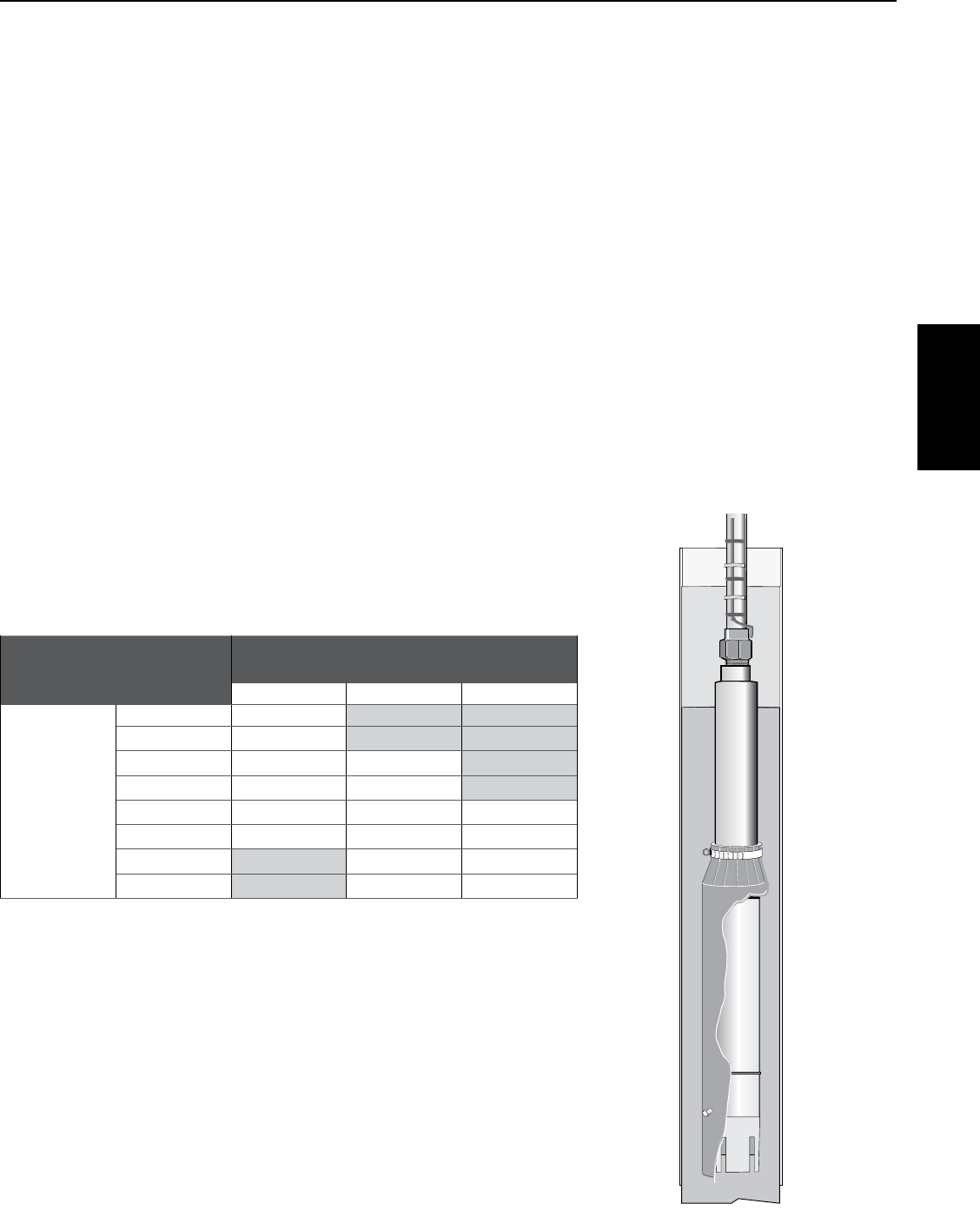
45
SECTION 7: Hitachi® 6” and Larger Submersible Motors
7.7 Overload Protection
Submersible motors must have Class 10 overload protection that will disconnect the power within 10 seconds in the
case of a locked rotor. To accomplish this, fixed-heater overloads are used. Refer to Section 10 for appropriate heaters.
The chart is based upon total line amps. Divide the motor amps by 1.732 when using a 6-lead motor with a Y-Delta
Starter. Notice: General Electric® overload heaters are only usable with General Electric overload relays. Do not adjust
relays to exceed nameplate amps.
7.8 Motor Cooling
Hitachi 6” motors are designed for minimum water flow of 0.5 ft. /sec. past the motor. Maximum water temperature is
95° F (35° C).
6” MOTORS: MINIMUM COOLING WATER FLOW
I.D of casing Flow (GPM) required
6 9
7 25
8 40
10 85
12 140
14 200
16 280
If the flow is less than specified, a flow-inducer sleeve can be installed. This will act like a smaller casing size, and
force flow around the motor to aid cooling. Always use a flow-inducer sleeve when the pump is in open water.
7.9 Head Loss In Casing
Use the chart below to account for the head loss around the pump.
7.10 Starting Frequency
To extend the life of the pump motor and control, limit the number of starts
to 100 per 24 hours. If higher starting frequencies are necessary, consult
your factory. To prevent overheating, run motor for a minimum of two
minutes. For starting frequency, refer to section 5.10.
Head loss in feet for flow past motor
6” MOTORS CASING INSIDE DIAMETER
6”
7”
8”
GPM
100
1.7
150 3.7
200 6.3 0.5
250 9.6 0.8
300 13.6 1.2 0.2
400 23.7 2.0 0.4
500 3.1 0.7
600 4.4 1.0
Hitachi 6” and
Larger Motors
General Electric® is a registered trademark of General Electric Company.

46
SECTION 7: Hitachi® 6” and Larger Submersible Motors
7.11 Troubleshooting
Problem Possible Causes Solution
Motor does not start but does not
blow fuses or relay
No power supply
Defective connections
Replace fuses, breakers or check for
loose or corroded connections and
motor lead terminals
Correct connections
Fuses or relay blow when motor
starts
Incorrect voltage
Incorrect fuses or relay
Defective capacitors
Wrong connections
Apply correct voltage. Voltage must
be plus or minus 10% of rated
(Nameplate)
Replace with proper fuses and relay
Replace with proper capacitors
Correct wrong connections or short
circuit.
Locked rotor conditions
Correct pump or well conditions
Insulation resistance down
Check the line and correct
Motor runs for a while and then
blown fuses or relay.
Low voltage or high voltage
Defective capacitors
Different control box for the motor
Defective starting voltage relay
Pump is sand clogged
Overheated protector
Apply rated voltage
Replace with proper capacitors
Replace with proper control box
Replace with proper relay
Pull pump and clean well
Shield the control box from heat
source
47
SECTION 8: Pentek Intellidrive™ Variable Frequency Drives
Important Safety Instructions
SAVE THESE INSTRUCTIONS - This manual contains
important instructions that should be followed during
installation, operation, and maintenance of the Pentek
Intellidrive Variable Frequency Drive (VFD).
This is the safety alert symbol. When you see this
symbol on your Pentek Intellidrive or in this manual,
look for one of the following signal words and be alert
to the potential for personal injury!
indicates a hazard which, if not avoided,
will result in death or serious injury.
indicates a hazard which, if not avoided,
could result in death or serious injury.
indicates a hazard which, if not avoided,
could result in minor or moderate injury.
NOTICE addresses practices not related to
personalinjury.
Carefully read and follow all safety instructions in this
manual and on the Pentek Intellidrive.
Keep safety labels in good condition. Replace missing
or damaged safety labels.
California Proposition 65 Warning
This product and related accessories
contain chemicals known to the State of California to
cause cancer, birth defects or other reproductive
harm.
Risk of high-voltage electrical shock
from EMI/RFI filter inside drive. Can shock, burn or
kill if the front cover of the Pentek Intellidrive is open
or removed while power is connected to the Drive or
the Drive is running. The front cover of the Drive must
be closed during operation.
• Makeallwiringconnections,thencloseandfasten
the cover before turning on power to drive.
• NEVER open the box when power is connected to
Drive.
• Beforedoinganyserviceormaintenanceinside
Drive or when connecting or disconnecting any wires
inside Drive:
1. DISCONNECT power.
2. WAIT 5 minutes for retained voltage
todischarge.
3. Open box.
• Beforestartinganywiringorinspectionprocedures,
check for residual voltage with a voltage tester.
• NEVER connect power wiring to
Drive
before
mounting the box.
• NEVER handle or service
Drive
with wet or damp
hands. Always make sure hands are dry before
working on
Drive
.
• NEVER reach into or change the cooling fan while
power is applied to Drive.
• NEVER touch the printed circuit board when power
is applied to Drive.
Risk of fire. Can cause severe injury,
property damage or death if installed with incorrect
or inadequate circuit breaker protection. To ensure
protection in the event of an internal fault in the
Pentek Intellidrive, install the Drive on an independent
branch circuit protected by a circuit breaker (see
Table 2 for circuit-breaker sizing), with no other
appliances on the circuit.
Risk of burns. The Drive can become hot
during normal operation. Allow it to cool for
5minutes after shut-down and before handling it to
avoid burns.
NOTICE To avoid damage to Drive or problems with
Drive:
• Connectoutputcablesto3-wire 1-phase and
3-phase submersible motors as follows:
Red to R, Yellow to Y, Black to B.
Any other order will reverse the motor rotation and
may damage the motor.
• Connectoutputcablesto2-wire 1-phase
submersible motors as follows:
Connect to Y and B only.
Connect Ground to green screw.
• Aboveground3-phasemotorsmayhavedifferent
lead colors. Generally connect output leads
asfollows:
R to L1, Y to L2, B to L3.
Verify rotation after startup.
• Donotmodifyequipment.
• Donotusepowerfactorcorrectioncapacitorsas
they will damage both motor and
Pentek Intellidrive
.
• Donotremoveanypartsunlessinstructedtodoso
in Owner’s Manual.
• DonotuseamagneticcontactoronDrivefor
frequent starting/stopping.
• DonotinstalloroperateDriveifitisdamagedor
parts are missing.
• BeforestartingDrivethathasbeeninstorage,
always inspect it and test operation.
• Donotcarryoutamegger(insulationresistance)
test on the control circuit of the
Drive
.
• Donotallowlooseforeignobjectswhichcanconduct
electricity (such as screws and metal fragments)
inside Drive box at any time. Do not allow flammable
substances (such as oil) inside Drive box at any time.
• GroundDriveaccordingtotherequirementsofthe
National Electrical Code Section 250, IEC536 Class
1, or the Canadian Electrical Code (as applicable) ,
and any other codes and ordinances that apply.
• Allinstallation,servicework,andinspectionsmust
be done by qualified electrician.
PENTEK
INTELLIDRIVE
8.1 General Safety
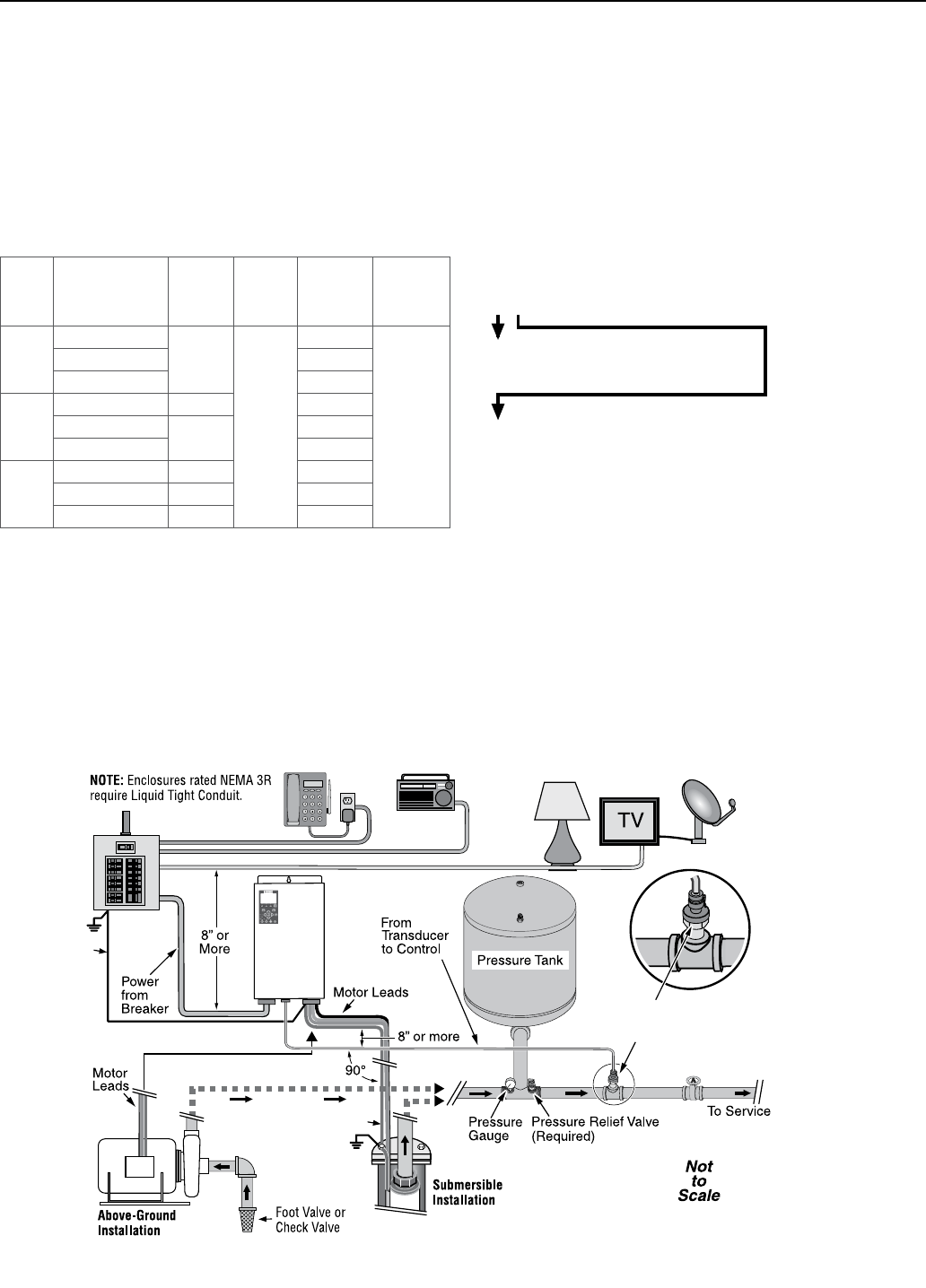
48
SECTION 8: Pentek Intellidrive™ Variable Frequency Drives
Specifications/Ratings
Input Voltage ...................... 1-Phase 230VAC Nominal (190–265VAC)
Input Frequency ..................................................................... 50/60Hz
Ambient Temperate Range .................... -4 to 122 °F (-20° to 50 °C)
Output Connections .........................3-Phase, 3-Wire/1-Phase or
1-Phase/2-Wire
Max Motor Cable Length .................................................... 1,000 feet
Enclosure ........................................................................................ 3R
Table 1 - Specifications
Model Motor Type HP
Range
Input
Voltage
Maximum
Output
AMPS
Enclosure
Type
PID10
2-WIRE* 1-PHASE
0.5–1 HP
190V –
265V
9.5A
NEMA 3R
outdoor
3-WIRE* 1-PHASE 7.5A
3-PHASE 5A
PID20
2-WIRE* 1-PHASE 0.5–1.5 HP 11A
3-WIRE* 1-PHASE 0.5–2 HP 13.5A
3-PHASE 8.5A
PID50
3-PHASE 0.5–5 HP 18A
2-WIRE 0.5 - 1.5 11A
3-WIRE 0.5-2 13.5A
* Select drives by S.F. amps of pump motor.
The Pentek Intellidrive is specifically designed to
operate 4” submersible pumps and 3-phase above
ground pumps in water well and residential booster
applications. Each Drive is rated for maximum output
amp rating. Any use of Drive outside of intended
design parameters will void warranty. If Drive is used
with above ground motors not rated for a Variable
Frequency Drive, maximize motor life by limiting lead
length to 25 ft. Refer to pump Owner’s Manual and the
National Electrical Code for proper wire size.
Each carton contains:
• Pentek Intellidrive Variable Frequency Drive
•PressureTransducer
•10’PressureTransducerCable
•QuickStartGuide
6004 0509
Transducer; install in straight
pipe downstream of tank, at
least one foot away from
pipe fittings on each side.
Gnd
(3 phase only)
PENTEK
INTELLIDRIVE™
Gnd
PIDXX
Product Family
PID - PENTEK INTELLIDRIVE
HP Range
10 = up to 1.0 HP
20 = up to 2.0 HP
50 = up to 5.0 HP
The PID10 will operate a 1-Phase 2-Wire, 1-Phase
3-Wire, and 3-Phase motor up to 1HP.
The PID20 will operate a 1-Phase 2-Wire up to 1.5HP
and a 1-Phase 3-Wire or 3-Phase motor up to 2HP.
The PID50 will operate a 1-Phase 2-Wire up to 1.5HP,
1-Phase 3-Wire up to 2HP, or 3-Phase motor up to 5HP.
8.2 Description
Figure 1 - A typical residential installation layout
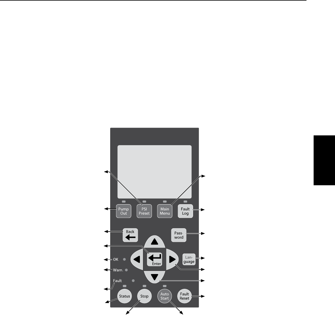
49
SECTION 8: Pentek Intellidrive™ Variable Frequency Drives
Transducer
The Pentek Intellidrive uses a 4-20mA, 0-100PSI
pressure transducer to control motor speed (max
is 300 PSI transducer).
The transducer (see Figure 1) senses pressure
in the pipe and converts it to an electrical signal.
The Drive senses and processes the signal in the
PID (Proportional, Integration, Derivative) control.
When operating in AUTOSTART mode, the Drive
increases and decreases the speed of the pump
motor as needed to maintain constant pressure in
the piping system.
Keypad
The keypad programs the Drive, monitors the
status of the pump, and displays faults if they
occur. Each button has a unique function, as
described in Figure 2. The LCD display shows a
text display of the status of the Drive’s operation.
Other LEDs light up to indicate when certain
buttons are pressed or certain events occur.
Fan
The Drive uses a thermostatically controlled
internal fan which operates automatically when
necessary to cool the Drive components.
Figure 2 - Pentek Intellidrive keypad functions
6007 0412
Stops the motor.
Power is ON to Drive.
A fault has occurred.
Selects menu items and confirms
numeric value changes.
Displays Drive’s current operating
condition and changes display
parameters.
Changes display to previous screen.
Drive is in Warning Mode (TPM); refer to
Troubleshooting section.
Changes internal pressure setpoint
from 15 PSI to transducer max -3PSI
(default is 60 PSI).
Runs the Drive at 45Hz (with no
pressure control) to allow installer to
pump out well.
Up and down arrows scroll through
menus and change numeric values.
Toggles between English, Spanish, and
French (default is English).
Resets fault that stopped Drive/pump.
With code, locks and unlocks password
protected keys.
Left and right arrows move cursor.
Shows last 15 faults.
Checks for line fill, then starts pump
in constant pressure mode.
Views and changes
parameters.
PENTEK
INTELLIDRIVE

50
SECTION 8: Pentek Intellidrive™ Variable Frequency Drives
Table 2 - Circuit breaker and wire sizes
Motor Drive
Model Volts Motor HP Wire Size* Circuit
Breaker** Generator (kVA)***
Input Output
2-wire PID10
230
1/2 14 14 15 2.2
3/4 12 12 3.1
1 20 4.4
PID20 1-1/2 10 10 25 5.3
3-wire
PID10
1/2 14 14
15
2.3
3/4 12 12 3.0
1 3.5
PID20 1-1/2 10 10 25 5.3
2 5.8
3 phase
PID10
1/2 14 14 15
2.1
3/4 2.8
112 3.4
PID20 1-1/2 12 20 4.4
210 25 5.5
PID50 3 10 30 7.3
5 6 8 50 12.6
* AWG will change depending on the length of wire. See Tables 3-6.
** With properly-sized circuit breakers, the Drive is protected from short circuit on the input and the output. There is no risk of
fire or electrical shock due to a short circuit. The Drive has NEC Class 10 overload protection.
*** Minimum 240V generator size.
NOTICE Information in Tables 3-6 applies ONLY to Pentek® motors. For other motors, refer to motor manufacturer
specifications for wire sizing.
Table 3 - Service Entrance to Drive - 1 Phase, 2-Wire 40°C Ambient, and 5 percent Voltage Drop,
60C and 75C Insulation (copper only).
Motor Rating Maximum Cable Length in feet (M)
Volts HP SFA 14 AWG 12 AWG 10 AWG 8 AWG 6 AWG 4AWG
230
1/2 4.7 447 (136) 712 (217) 1000 (305) –
–
–
3/4 6.2 341(104) 542 (165) 864 (263) 1000 (305)
1 8.1 261(79) 415 (126) 661 (202) 1000 (305)
1 1/2 10.4 203 (62) 323 (98) 515 (157) 816 (249) 1000 (305)
2 12.2 173 (53) 275 (84) 439 (134) 696 (212) 1000 (305)
3 10.1 209 (64) 333 (101) 530 (162) 840 (256) 1000 (305)
5 17.5 121(37) 192 (59) 306 (93) 485 (148) 754 (230) 1000 (305)
8.3 Installation
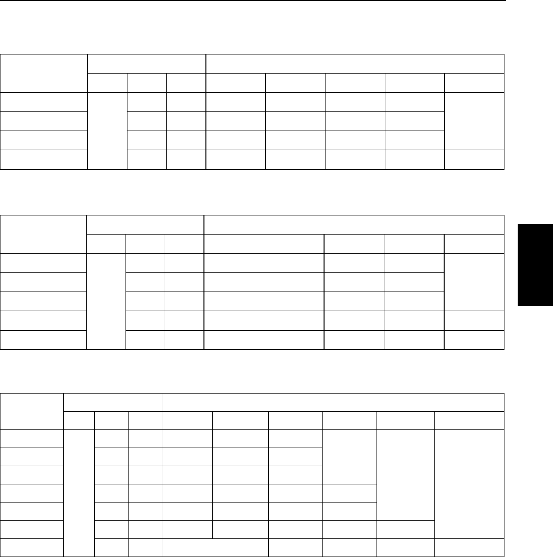
51
SECTION 8: Pentek Intellidrive™ Variable Frequency Drives
Table 4 - AWG Wire Sizing, Drive to 1-Phase, 2-Wire Motor, 40°C Ambient, and 5 percent Voltage Drop,
60C and 75C Insulation (copper only).
Motor P/N Motor Rating Maximum Cable Length in feet (M)
Volts HP SFA 14 AWG 12 AWG 10 AWG 8 AWG 6 AWG
P42B0005A2-01
230
1/2 4.7 447 (136) 712 217) 1000 (305) –
–P42B0007A2-01 3/4 6.2 341 (104) 542 (165) 864 (263) 1000 (305)
P42B0010A2-01 1 8.1 261 (80) 415 (126) 661 (201) 1000 (305)
P42B0015A2-01 1 1/2 10.4 203 (62) 323 (98) 515 (157) 816 (249) 1000 (305)
Table 5 - AWG Wire Sizing, Drive to 3-Wire, 1-Phase Motor, 40°C Ambient, and 5 percent Voltage Drop,
60C and 75C Insulation (copper only).
Motor P/N Motor Rating Maximum Cable Length in feet (M)
Volts HP SFA 14 AWG 12 AWG 10 AWG 8 AWG 6 AWG
P43B0005A2-01
230
1/2 4.8 440 (134) 700 (213) 1000 (305) –
–P43B0007A2-01 3/4 6352 (107) 560 (171) 893 (272) 1000 (305)
P43B0010A2-01 1 7.3 289 (88) 460 (140) 734 (224) 1000 (305)
P43B0015A2-01 1 1/2 10.9 194 (59) 308 (94) 492 (150) 778 (237) 1000 (305)
P43B0020A2-01 2 12.2 173 (53) 275 (84) 439 (134) 696 (212) 1000 (305)
Table 6 - AWG Wire Sizing, Drive to 3-Phase Motor, 40°C Ambient, and 5 percent Voltage Drop, 60C
and 75C Insulation (copper only).
Motor P/N Motor Rating Maximum Cable Length in feet (M)
Volts HP SFA 14 AWG 12 AWG 10 AWG 8 AWG 6 AWG 4 AWG*
P43B0005A3
230
1/2 2.9 728 (222) 1000 (305) –
–
__
P43B0007A3 3/4 3.9 541 (165) 861 (262) 1000 (305)
P43B0010A3 1 4.7 449 (137) 715 (218) 1000 (305)
P43B0015A3 1 1/2 6.1 346 (105) 551 (168) 878 (268) 1000 (305)
P43B0020A3 2 7.6 278 (85) 442 (135) 705 (215) 1000 (305)
P43B0030A3 3 10.1 209 64) 333 (101) 530 (162) 840 (256) 1000 (305)
P43B0050A3 5 17.5 306 (93) 485 (148) 754 (230) 1000 (305)
*Installations that require wire gauge larger than 6AWG will require an external junction box. Run
6AWG wire from the Drive into the junction box, then make external connections with wire nuts to
appropriately sized wire.
PENTEK
INTELLIDRIVE
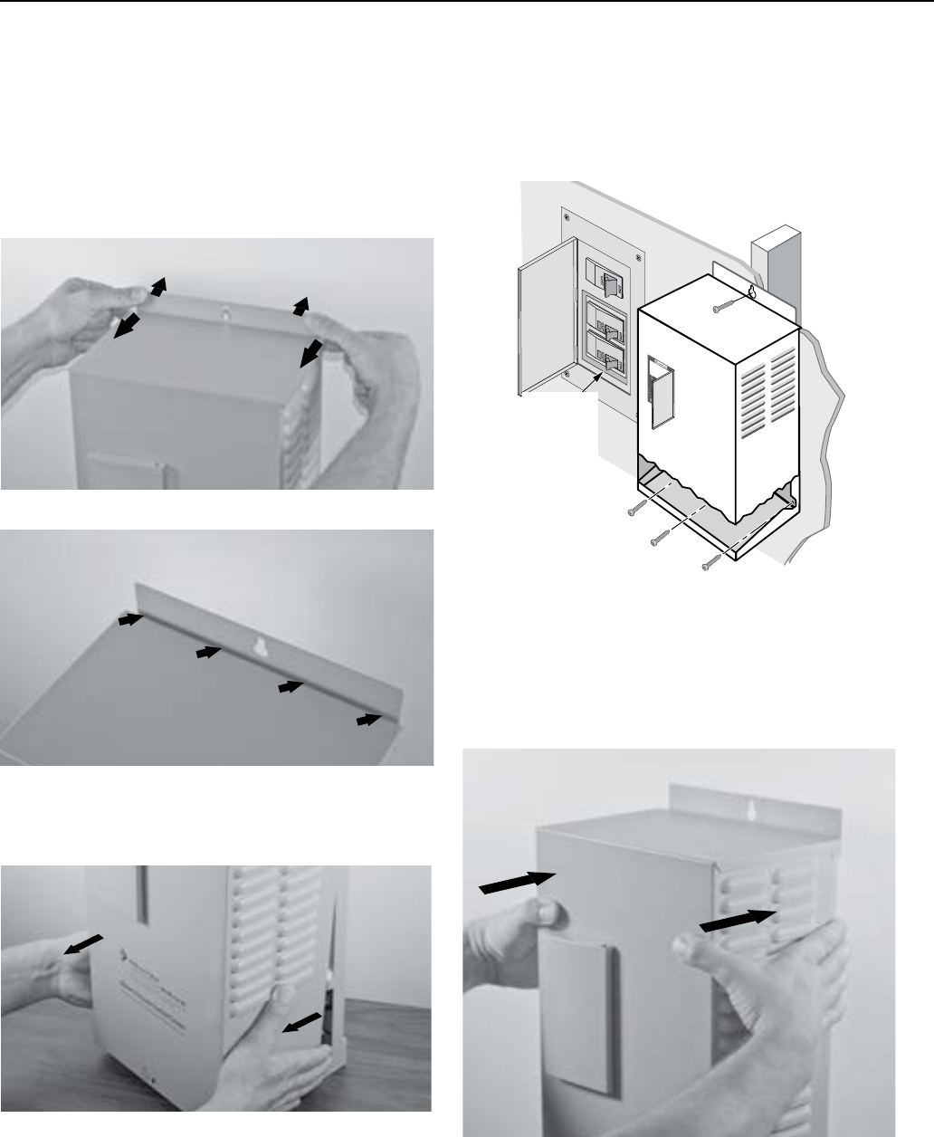
52
SECTION 8: Pentek Intellidrive™ Variable Frequency Drives
Mounting the Drive
To mount the Drive as shown in Figure 6, follow
this procedure:
1. First, remove the cover by backing out screw
at bottom of front cover.
2. Push on backplate with thumbs while pulling
the cover toward you with index fingers,
creating a gap. See Figures 3 and 4.
3. Pull bottom of cover towards you; lift up on
cover and remove. See Figure 5.
4. With the cover removed, permanently mount
the Drive using the top slotted hole, plus
either the three bottom holes (for flat surface
mounting) or the center bottom hole (for
attaching to a post or stud). See Figure 6.
Gap
Figure 3 - Separate cover and backplate
Figure 4 - Gap between cover and backplate
Figure 5 - Pull out bottom of cover
5. Ensure the Drive’s ventilation holes are
not blocked and there is enough space
around it to allow free air flow (minimum
3” clearance on top, bottom, and sides).
See Figure 6. Once the Drive is mounted,
electrical wiring can be connected.
6. To reattach the Drive cover, hook the top of it
on backplate (be sure to leave a gap). Lower
bottom of cover into place. Push cover evenly
against backplate, eliminating the gap. See
Figure 7.
7. Replace screw at bottom of front cover.
5997 0412
Figure 6 - Attaching Drive to wall
Typical
230VAC
Circuit
Breaker
(Double
Width)
Figure 7 - Reattaching Drive cover
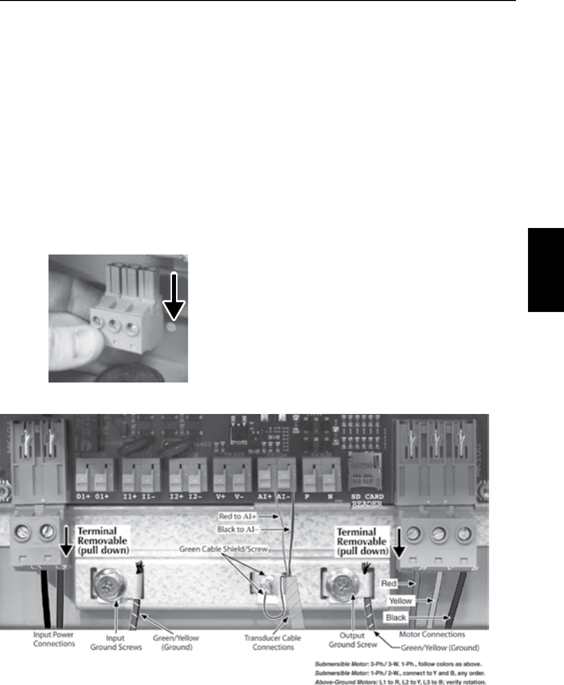
53
SECTION 8: Pentek Intellidrive™ Variable Frequency Drives
Figure 9 - Basic Wiring Connections for Startup
Wiring
To allow for ease of wiring, the enclosure
wiring area is free of electronics other than
the terminals. Conduit holes and knockouts
are located so that the wire can be fed straight
through to the connectors, with minimal bending.
The terminals accept 6-14 AWG wire.
Installations that require larger wire gauge than
6AWG will require an external junction box. Run
6AWG wire from the Drive into the junction box,
then make external connections with wire nuts to
appropriately sized wire.
NOTICE For convenience in wiring, the input and
motor terminals unplug from the box. Pull them
down to remove them for ease of access, as
shown in Figure 8.
Verify that the terminal connectors are completely
seated when you replace them. It is best practice
to connect all output wires (larger wire gauge)
first, then all input wires.
Pump Connections
If the Pentek Intellidrive is used with above ground
motors not rated for Variable Frequency Drive
use, maximize motor life by limiting lead length
to 25 ft. Refer to the pump owner’s manual, the
National Electrical Code, and local codes for
proper wire size.
The output of the Drive is single phase (2-wire or
3-wire) or 3-phase, depending on motor selection
during startup.
The output power terminals (motor wire
connections) are located on the lower right side of
the Drive and are labeled R (Red), Y (Yellow), and
B (Black). See Tables 2 through 6 for suggested
wiresizes.
NOTICE 2-wire 1-phase connect to Y + B, not R + B.
Feed the motor cable through the 3/4” conduit
hole on the bottom right side and into the
appropriate terminals. If the wire is large enough
to require a larger conduit hole, remove the
1-1/4” knockout and use the appropriate conduit
connections. Attach the motor ground wire to the
grounding screw, located to the upper right of the
terminal block. Attach the motor power wires to
the terminals as shown in Figure 9.
NOTICE Drive does not sense motor temperature
and will not protect motor from over heating.
5999 0509
Figure 8 - Pull input and motor terminals down
to remove, making wiring easier.
PENTEK
INTELLIDRIVE

54
SECTION 8: Pentek Intellidrive™ Variable Frequency Drives
Pressure Tank Recommendations
Minimum tank size is two gallons. Use a pre-
charged pressure tank with Drive, as shown in
Figure 1. The tank size must equal at least 20
percent of the pump’s rated flow in gallons per
minute (GPM), but cannot be less than two gallons
capacity. For example, a pump rated at 7GPM
would require a tank of two gallons capacity or
larger. A pump rated at 50 GPM would require a 10
gallon tank or larger. Tanks larger than 10gallons
can be used, but may require adjustment of Wake
Delayparameter.
Table 7 - Control Pressure Set Point and Tank
Pre-Charge Pressure Values (PSI).
Pressure
Point
Setting
(PSI)
Precharge
Pressure
(PSI)
Pressure
Point
Setting
(PSI)
Precharge
Pressure
(PSI)
25 18 65 46
30 21 70 49
35 25 75 53
40 28 80 56
45 32 85 60
50 35 90 63
55 39 95 67
60
(Default) 42 –
NOTICE Set pressure tank’s pre-charge to 70
percent of the system operating pressure. When
using an external set point as well as an internal
set point, pre-charge tank to 70 percent of the
lower setpoint of the two. Some applications may
require a different percentage when determining
the setpoint.
Transducer Connections
A 0-100 PSI 4-20 mA transducer is provided
with Drive. Install the transducer downstream of
tank, as shown in Figure 1. Install transducer in
a tee in a straight section of pipe with at least 1
foot of straight pipe on each side of the tee (i.e.,
all fittings must be at least 1 foot away from
transducer).
Feed transducer cable through the open 1/2”
conduit hole on bottom of the Drive enclosure.
As shown in Figure 9, connect the red wire of the
transducer cable to AI+, connect black wire to AI–,
and connect the green cable shield to the metal
cable shield screw.
To connect the transducer wires:
1. Strip wire ½ inch
2. Push spring terminal up with finger or slotted
screwdriver
3. Insert wires from bottom
4. Release spring terminal
Input Power Connections
The input power terminals are located on the
lower left side and are marked L1 and L2 (see
Figure 9). There is a ground screw for the input
ground wire to the right of the connector (torque
to 10 in lb). Feed wire through the 3/4” conduit
hole on the bottom left side and into appropriate
terminals. If wire is large enough to require a
larger conduit hole, remove the 1-1/4” knockout
and use appropriate conduitconnections.
To determine the correct wire sizes for
installation, see Table 3.
NOTICE The Pentek Intellidrive only accepts 230V
single phase input power. If incoming power does
not match this, have a qualified electrician alter
supply voltage to 230V/1Ph before connecting it to
the Drive. See specifications ratings in Section 8.2.
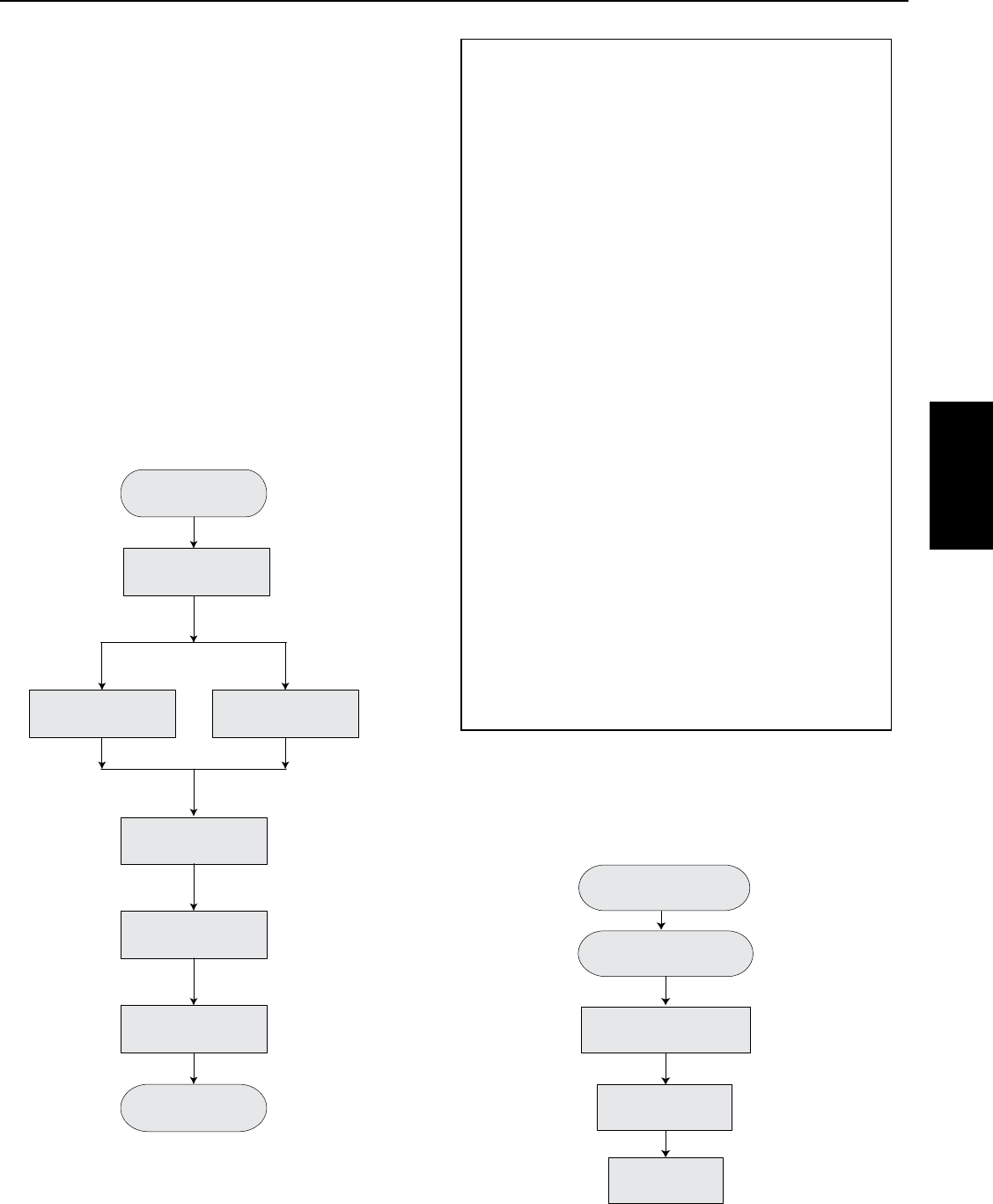
55
SECTION 8: Pentek Intellidrive™ Variable Frequency Drives
Ensure that the cover is installed before operating
the
Pentek Intellidrive.
Most installations will only require the initial
startup settings. However, the installer may need
to set additional parameters. Information about
accessing all parameters, explanations of their
functions, and procedures for changing parameter
values, will be found later in this section.
1. Program the Drive: Apply power to the
Pentek Intellidrive. Setup Guide will appear in
the display. Follow keypress sequence shown in
Figure 10.
NOTICE If Setup Guide does not appear, refer to
Drive Reset Procedure, Figure 20.
2. Select 80 Hz Operation, if necessary (See 60 Hz
to 80Hz Operation for more information):
A. Press MAINMENU button.
B. Follow the keypress sequence shown in
Figure11.
Service Factor Amps
To maximize pump performance, be sure to
enter the correct Service Factor Amps (SF
Amps) in the
Pentek Intellidrive
.
• EnteringSFAmpshigher than the motor
rating lets the Drive supply more amps to the
motor than the motor is designed for and may
allow the motor to overheat (see Table 8).
• EnteringSF Ampslower than the motor
rating limits the output amps to less than
the motor is designed for and will reduce the
performance of the pump.
• Forany1-Phase3-Wiremotor,thecorrect
Service Factor Amp rating for the Drive is Cap
Start/Cap Run amps (see Table 8). This may
not match the motor nameplate, which (for a
Single Phase, 3-Wire motor) will generally be
Cap Start/ Induction Run Amps.
• Forany3-Phaseor1Phase,2-Wiremotor,
use the motor nameplate Service Factor
Amprating.
NOTICE
Pentek®
submersible motors may
differ from motors of the same horsepower
from other manufacturers. For 1-Phase,
3-Wire motors from all other submersible
motor manufacturers, enter the motor
manufacturer’s CS/CR service factor amps for
your motor. For 3-Phase or 2-Wire 1-Phase
motors, use the motor nameplate amp value.
Also see Retro Fit Applications.
Press Enter
Press Enter
Press Enter
Press Enter
6566 0512
Apply 230V to Drive
Set Time
Set Date
Setup Complete
1 Phase
Connection Type
(2 Wire or 3 Wire)
3 Phase
Motor Type
Subm or Above Gnd
Enter Service
Factor Amps
Enter Motor Phase
(1 Phase or 3 Phase)
Press Enter
Press Enter
Figure 10 - Drive Setup Guide.
6570 0512_EN
Use arrows to
scroll to Motor
Press Enter
Use arrows to
select 80 Hz
Press Enter
to save
Press MAIN MENU
button
Press Enter
Use arrows to select
Max Frequency
Figure 11 - Select 80 Hz (3-phase operation only).
8.4 Initial Startup and Programming
Procedures
PENTEK
INTELLIDRIVE
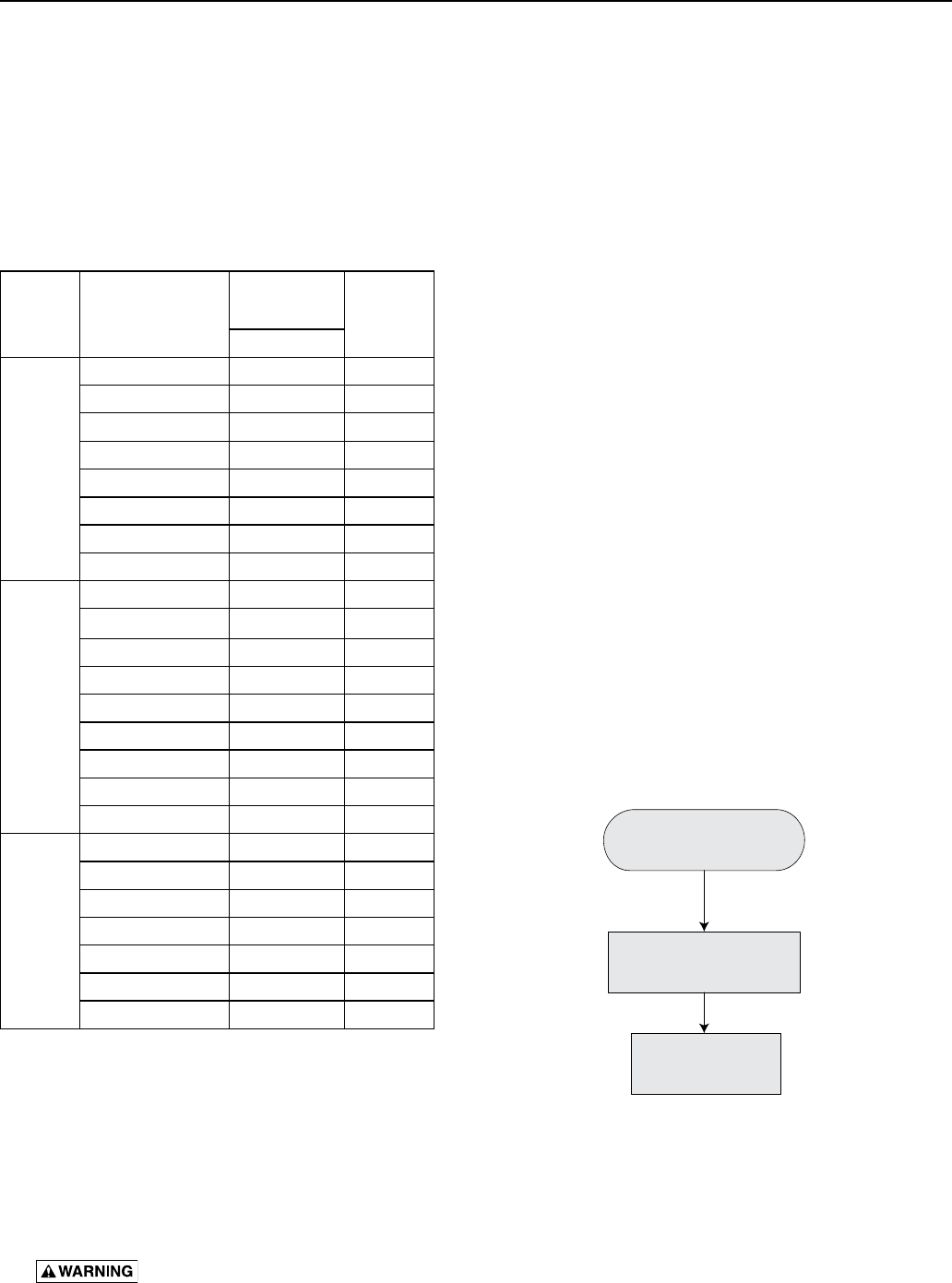
56
SECTION 8: Pentek Intellidrive™ Variable Frequency Drives
3. Pump out well (if necessary):
Direct pump’s discharge to appropriate location
not connected to system and press Pump Out.
Drive will ask “Is a valve open?” Change “No”
to “Yes”, press enter. The pump will run at 45 Hz.
Adjust frequency as appropriate:
A. Press ENTER
B. Change frequency value
NOTICE Above ground pumps should run at 60
Hz for this step (until pump is primed). Then
adjust frequency as necessary.
C. Press ENTER again.
Run the Drive in this mode until the well
discharge runs clear, then press STOP button to
stop Drive.
Risk of explosion. In Pump Out
mode, pump runs at a constant speed. All
pressure functions are not working, there is no
sleep or Dry Run Protection which can cause very
high pressure if flow is restricted.
4. Verify installation: Make sure that the system
has properly-sized, pressure-relief valve and
pressure tank.
Make sure pressure tank’s precharge is correct.
See Table 7.
Make sure pump discharge is connected to
system.
5. System Start:
A. Open valves at the ends of lines so that air
will escape during pressurization.
B. Press Auto Start; close valves at the ends of
lines after all air has escaped.
C. The system goes into Constant Pressure
Operation as soon as the transducer
registers the Dry Run Sensitivity parameter
(default is 10 PSI). If system pressure does
not reach thatPSI value within 3 minutes,
the Drive will stop. Press Auto Start again to
restart line fill. If longer priming or line fill
time is required, adjust Fill Time parameter.
See Table 9.
Changing a Parameter Value
This procedure works for ANY parameter.
A. Press MAINMENU button.
B. Follow the keypress sequence shown in
Figure12:
A shorthand way to remember this is:
• PressENTERtochangeavalue
• PressENTERagaintosaveit
• Ifnewvalueisnotsaved,anyscreenchangewill
result in the loss of the new value.
Table 9 lists all available commands and
parameters for the Pentek Intellidrive.
6567 0512
Use arrows to
find parameter
Use arrows
to change value
Press Enter
to save
Press Enter
Figure 12 - Changing parameter value.
Table 8 - Pentek Motor Service Factor Amps
Motor
Type
PENTEK® Part
Number
Rating @
230V
Service
Factor
Amps
HP
2-Wire
P42B0005A2-01 1/2 4.7
P42B0007A2-01 3/4 6.2
P42B0010A2-01 1 8.1
P42B0015A2-01 1-1/2 10.4
P42B0005A2 1/2 4.7
P42B0007A2 3/4 6.4
P42B0010A2 1 9.1
P42B0015A2 1-1/2 11.0
CS/CR
3-Wire
P43B0005A2-01 1/2 4.8
P43B0007A2-01 3/4 6.0
P43B0010A2-01 1 7.3
P43B0015A2-01 1-1/2 10.9
P43B0005A2 1/2 4.9
P43B0007A2 3/4 6.3
P43B0010A2 1 7.2
P43B0015A2 1-1/2 11.1
P43B0020A2 2 12.2
3-Phase
P43B0005A3 1/2 2.9
P43B0007A3 3/4 3.9
P43B0010A3 1 4.7
P43B0015A3 1-1/2 6.1
P43B0020A3 2 7.6
P43B0030A3 3 10.1
P43B0050A3 5 17.5
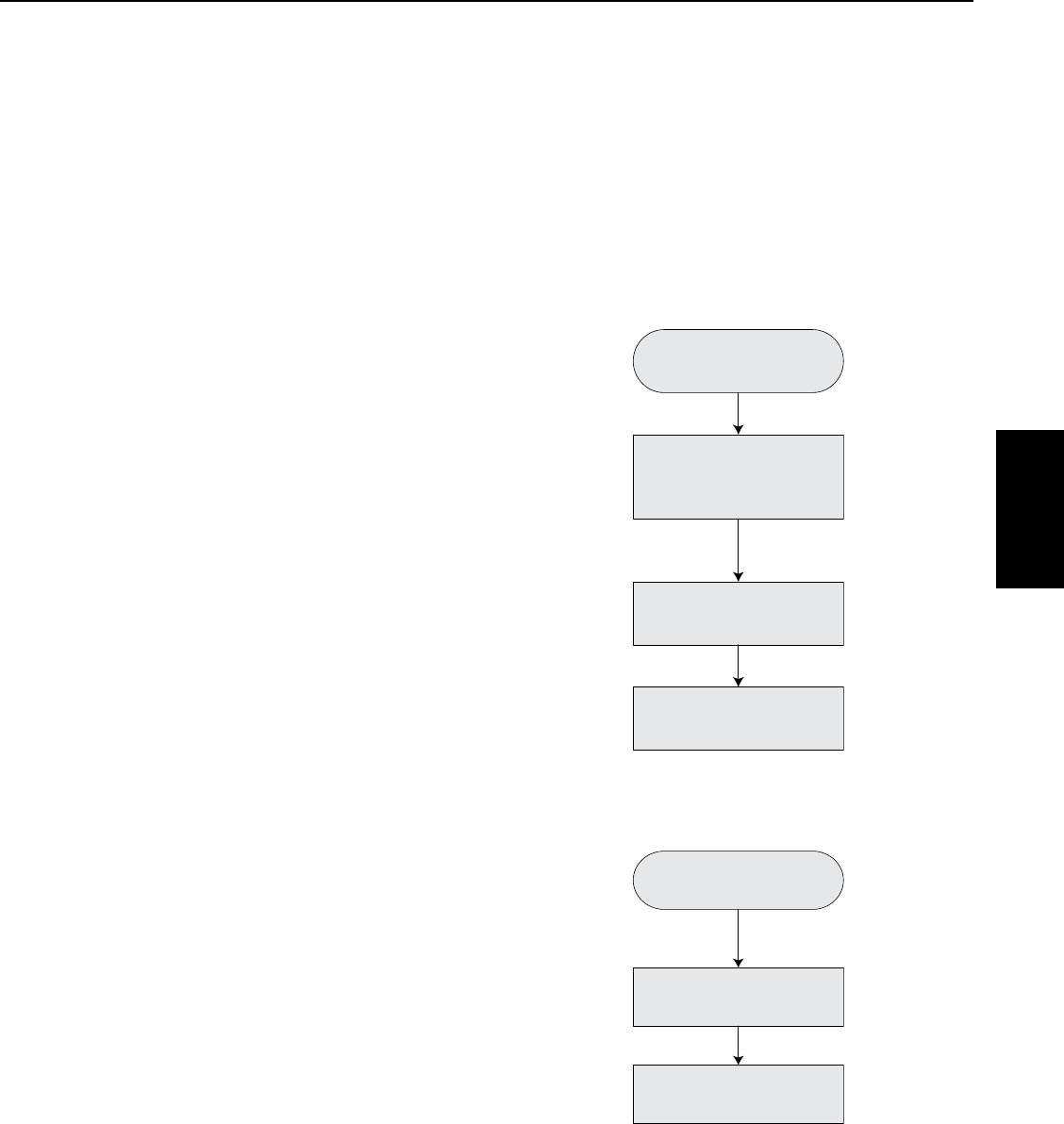
57
SECTION 8: Pentek Intellidrive™ Variable Frequency Drives
60 Hz to 80 Hz Operation
When installing the Pentek Intellidrive with a
motor and liquid end of the same HP rating,
operate it at 60 Hz (the default value). The Drive
can be operated at frequencies of up to 80 Hz
when the installation uses a 3-phase motor
2 times the size of the pump. For example, a
1 HP pump with a 2 HP 3-phase motor. This
combination will equal the performance of a
conventional 2HPpump.
Press Main Menu and
follow the keypress sequence
shown in Figure11
. Be sure to press ENTER to
save the new Max Frequency selected. The Drive
will now use the new value selected.
NOTICE The Drive will not allow the output amps
to go above the Service Factor Amps selected
on the keypad. Because of this, some 80 Hz
operations may be limited. This protects the
motor and may be a commonoccurrence in a
80Hz operation.
Keypad Lock - Password
The password locks or unlocks the blue buttons
on keypad. All Pentek Intellidrive units are shipped
from factory with the default password 7777. It
can be changed to any other 1 to 4 digit number.
To reset password to a unique password for unit,
unlock keypad (see below) and follow the keypress
sequence shown in Figure 12 to make the change.
If installer does not press the password button,
then the keypad will automatically lock 60 minutes
after the Drive is powered up. The time out period
is adjustable (see Table 9).
To unlock keypad press Password, use directional
arrows to select numeric code and press ENTER.
NOTICE For more detailed information on keypad
functions, see Figure 2.
Pump Out Operation
Press Pump Out. The Drive will start pump in a
constant speed mode (default 45 Hz). The pump
will run until STOP or Auto Start are pushed.
If speed change is necessary, press enter, to
highlight value use arrows to change value then
press enter to save.
Setting the Pressure
NOTICE Default pressure setting is 60 PSI. If this
value is changed, adjust tank pressure accordingly
(see Table 7).
There are three ways to change the pressure
setpoint:
1. While running the pump
• Follow keypress sequence shown in Figure
13 to make desiredchange. This parameter
allows either Internal or External Setpoint
to be changed, depending on which one is
referenced at the time the change is made.
2. Via the PSI Preset (Figure 14)
3. Via the Main Menu (Main Menu/Settings/
Setpoint/Internal Setpoint)
6569 0512
Press PSI Preset
Use arrows to
change the value
Press Enter to Save
Press Enter
Figure 14 - Change PSI Internal Setpoint
using PSIPreset.
6568 0512
Press Auto Start
if pump is not running
Use arrows to
change the value
Press Enter to Save
Press Enter
Verify
“Running Fixed Press”
displayed on screen
Figure 13 - Change PSI Setpoint while running
pump.
8.5 Advanced Programming
PENTEK
INTELLIDRIVE

58
SECTION 8: Pentek Intellidrive™ Variable Frequency Drives
Table 9 - Main Menu and Parameters
Menu
Settings Parameter Unit of
Measure
Value Description
Default Min. Max.
Time/Date
Hour Format Hours 12Hr 12Hr 24Hr Selects 12 or 24 hour time scale.
Time HH:mm 1:00 AM 1 24 Sets current time. Used for time
stamp in fault log.
Date MM/DD/YYYY 1/1/12 – – Sets current date. Used for date
stamp in fault log.
PID Control
Proportional
Gain – 1500 0 10000
Sets the PID controller gain. Used
in conjunction with all PID Control
parameters to control how fast or
slow the Drive reacts to pressure
changes.
Integration
Time Milliseconds 500 ms 20 ms 65000
ms
Sets the PID controller integration
time. Used in conjunction with all
PID Control parameters to control
how fast or slow Drive reacts to
pressure changes.
Derivation
Time Milliseconds 60 ms 0 ms 10000
ms
Sets PID controller derivation
time. Used in conjunction with all
PID Control parameters to control
how fast or slow Drive reacts to
pressure changes.
Derivative
Limit – 120 0 2000 Sets derivative filter time constant
for PID controller.
Sleep
Boost
Differential PSI 3 PSI 3 PSI 10 PSI
First part of Boost Process.
Pressure boost that happens
before it goes to Wake Delay.
Boost Delay MM:SS 1 Min 30 Sec 5 Min
The time Drive takes to start
Boost Process after system has
stabilized.
Wake Up
Differential PSI 5 PSI 5 PSI 15 PSI Pressure amount below setpoint
that wakes up Drive.
Wake Delay MM:SS 15 Sec 3 Sec 2 Min
Second part of the Boost Process.
The time it takes to ramp down
pressure during the Boost Process.
Password
Password
Time Out HrHr:mm 1 Hr 1 Min 6 Hr
Amount of time it takes to lock
keypad (after last button is
pressed).
Password – 7777 0000 9999
Password used to unlock keypad.

59
SECTION 8: Pentek Intellidrive™ Variable Frequency Drives
Table 9 - Continued
Menu
Settings Parameter Unit of
Measure
Value Description
Default Min Max
Setpoints
Internal
Setpoint PSI 60 PSI 15 PSI
Max
Sensor
Value
minus
3 PSI.
Main pressure setpoint used. Sets
main system operational pressure.
This parameter is accessed here,
through PSI Preset button, or by
pressing Enter button while in
Constant Pressure operation.
External
Setpoint PSI 40 PSI 15 PSI
Max
Sensor
Value
minus
3 PSI.
Second pressure setpoint. When
another pressure setting is desired
other than Internal Setpoint.
Additional programming needed in
I/O section. Requires an external
switch or timer to wired to I1or
I2 terminals. It is only active
when there is voltage present
I1terminals
Sub Menu Parameter Unit of
Measure Default Max Min Description
Motor
Motor Phase _ 1 1 3
Selects phase of motor to be
operated. An additional sub menu
will appear, based on phase
selection, to select proper motor
type.
Connection
Type –3 wire 3 wire 2 wire
Wire type for 1 phase motor
operation only. Can only access
by first setting Motor Phase
parameter to 1 Phase.
Motor Type – Subm Subm Above
Gnd
Motor type for 3 phase motor
operation only. Can only access
by first setting Motor Phase
parameter to 3 Phase.
Service Factor
Amps A00.0 A 00.0 A
Per
drive
and
motor
Service factor amps (max. load) of
motor the Drive is operating. Sets
maximum allowed amps at output
of Drive. See Table 8 for values.
Min Frequency Hz 30 Hz 30 Hz 1 below
Max Hz
Minimum frequency (speed) motor
will run.
Max
Frequency Hz 60 Hz 1 above
Min Hz 80 Hz
Maximum frequency (speed)
motor will run. Up to 80Hz is only
available on only when Motor
Phase is set to 3 and motor type is
Sub.
Sensor Max Sensor
Value PSI 100 PSI 10 PSI 300 PSI
Maximum pressure value of
transducer sensor used with Drive.
Only change if different transducer
is used with Drive, other than 100
PSI max scale.
PENTEK
INTELLIDRIVE

60
Table 9 - Continued
Menu or
Sub Menu Parameter Unit of Measure Value Description
Default Min Max
Ex Runtime
Excessive
Runtime
Detection
_ Enabled
Disabled
Enabled Enables or disables Excessive Runtime
Detection.
Excessive
Runtime Hours Hours 24 1 100 Number of hours Drive can run before it
faults on Excessive Runtime.
Dry Run
Auto Restart
Delay Minutes 10 Min 3 Min 60 Min Time Drive waits to restart pump when
Dry Run is detected.
Number of
Resets – 3 0 5
Number of tries Drive attempts to
restart pump when Dry Run condition is
detected.
Detection Time M:SS 15 Sec 5 Sec 10 Min Time the Drive takes to recognize Dry
Run condition.
Sensitivity PSI 10 0 300
Pressure value that Dry Run condition
is detected at. Dry Run fault will occur
if this pressure cannot be met within
Detection Time window. Lower pressure
= less sensitivity.
Fill Time M:SS 1 M 15 S 10 M
Time allowed to fill (prime) pipes during
Auto Line Fill process. Relates to Dry
Run Sensitivity value. (Time starts after
55 Hz is reached).
I/O
Digital Input 1
– Unused – –
Selects operation of Drive when
terminal I1 or I2 is used. Select between
Unused, Run Enabled, Ext Fault, and
Setpoint. The Drive will respond to
selected command when voltage is
present at I1 or I2 terminal.
Digital Input 2
Relay Output – Unused – –
Selects the operation of Drive when
terminal O1 is used. Select between
Unused, Run, and Fault. The Drive
closes the Relay when Run or Fault is
selected.
Over Press Over Pressure PSI 80 PSI 15 PSI 97 PSI
Sets Over Pressure Warning value.
Change if higher than 80 PSI system
pressure is needed.
No Ground No Ground
Detection – Enabled
Disabled
Enabled
Selects whether Ground Detection
parameter is Enabled or Disabled. If
Disabled is selected, it will revert back
to Enabled after 72 hours. Warning LED
will flash entire time it is Disabled.
Reset Factory Reset – No No Yes
Resets all parameters to factory
defaults. Displays Setup Guide after it
is complete. Software version displayed
here. Does not clear fault log.
SW Update Software Update – Disabled Disabled Enabled Used to update software, if necessary.
SECTION 8: Pentek Intellidrive™ Variable Frequency Drives
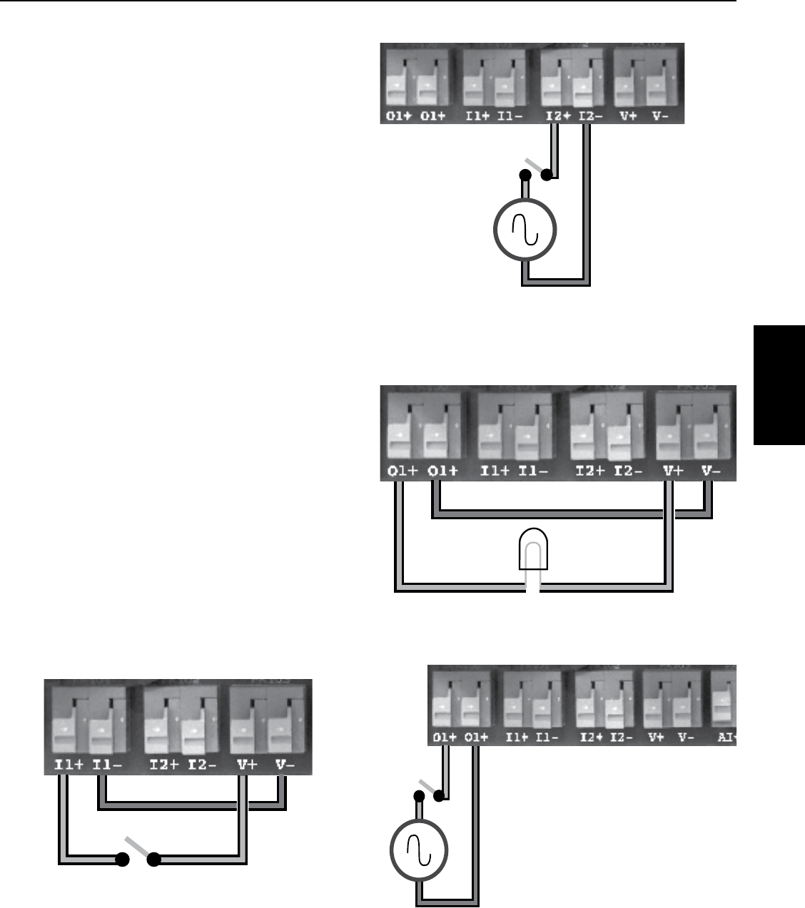
61
The I/O terminals are located in the center of
the wiring compartment, as shown previously in
Figure9.
The Digital Input connections (I1 and I2) are used to
control the Drive based on the state of an external
device, such as a flow switch, moisture sensor,
alternator, or other device. Programming is needed
to activate any of these functions (see Table 9).
The Output Relay (O1) is used to control an external
device based on two states of Drive; either Running
the pump or Faulted. Programming is needed to
activate any of these functions (see Table 9).
Cable Installation
Three 1/2” conduit knockouts are provided on the
bottom of the Drive enclosure for the I/O wires.
Break out the closest 1/2” knockout and route the
wires through. Use a cord grip to prevent the wire
from rubbing and causing a short.
NOTICE Never run low voltage I/O wire through
the same conduit hole as the 230V input wires or
motor wires.
To connect the external wires to the terminals:
1. Strip wire ½ inch
2. Push spring terminal up with finger or slotted
screwdriver
3. Insert wires from bottom
4. Release spring terminal
Connection Examples
Figures 15-18 show various connection schemes
for typical applications. Table 10 describes each
I/O terminal, including purpose and rating.
6540 0412
Figure 15 - Example Input with internal 24 volt
supply
6542 0412
Figure 17 - Example Output relay with internal
24 volt supply
Figure 16 - Example external Input with
externalsupply
6541 0412
115 VAC
or
230 VAC
or
240 VAC
+
-
Figure 18 - Example Output with externalsupply
SECTION 8: Pentek Intellidrive™ Variable Frequency Drives
8.6 I/O Connections
PENTEK
INTELLIDRIVE
6541 0412
115 VAC
or
230 VAC
or
240 VAC
+
-

62
Table 10 - I/O Function, Connections, Ratings
Label Function Connection Rating
AI+ Positive connection for transducer Red transducer wire 24 Volt
(supplied)
AI- Negative connection for transducer Black transducer wire
V+ Positive side of 24 volt power supply.
Used to power external devices.
Positive side of 24V external device, i.e.,
flow switch, moisture sensor, alternator,
etc. Need to complete the circuit with V-.
See Figures 15 and 17. 40mA maximum
output
V- Negative side of 24 volt power supply.
Used to power external devices.
Typically to I1-, I2-, or O1-. Used with a
flow switch, moisture sensor, alternator,
etc. Need to complete the circuit with V+.
See Figures 15 and 17.
I1+
Positive (dry contacts) connection of
Digital Input 1. Connect when using an
external device to control Drive.
From an external device i.e., flow
switch, moisture sensor, alternator, etc.
Requires complete circuit connection
with I1-. See Figures 15 and 16.
Accepts 24VDC
and up to
230VAC
I1-
Negative (dry contacts) connection of
Digital Input 1. Connect when using an
external device to control Drive.
Can be from V- or from the negative side
of an external power supply. Requires
complete circuit connection with I1+. See
Figures 15 and 16.
I2+
Positive (dry contacts) connection of
Digital Input 2. Connect when using an
external device to control Drive.
From an external device, i.e., flow
switch, moisture sensor, alternator, etc.
Requires complete circuit connection
with I2-. See Figures 15 and 16.
I2-
Negative (dry contacts) connection of
Digital Input 2. Connect when using an
external device to control Drive.
Can be from V- or from the negative side
of an external power supply. Requires
complete circuit connection with I2+. See
Figures 15 and 16.
O1+
Output relay (dry contacts) connection.
Programmed to close when pump is
Running or Faulted.
Positive wires of an external device. See
Figures 17 and 18. Accepts up
to 5Amps at
24VDC and
8Amps at up to
230VAC
O1+
Output relay (dry contacts) connection.
Programmed to close when pump is
Running or Faulted.
Positive wires of an external device. See
Figures 17 and 18.
PPositive connection of an RS-485
communication device (see Figure 19). Positive wire from RS-485 device. Per RS-485
Standard
NNegative connection of an RS-485
communication device (see Figure 19). Negative wire from RS-485 device.
SECTION 8: Pentek Intellidrive™ Variable Frequency Drives
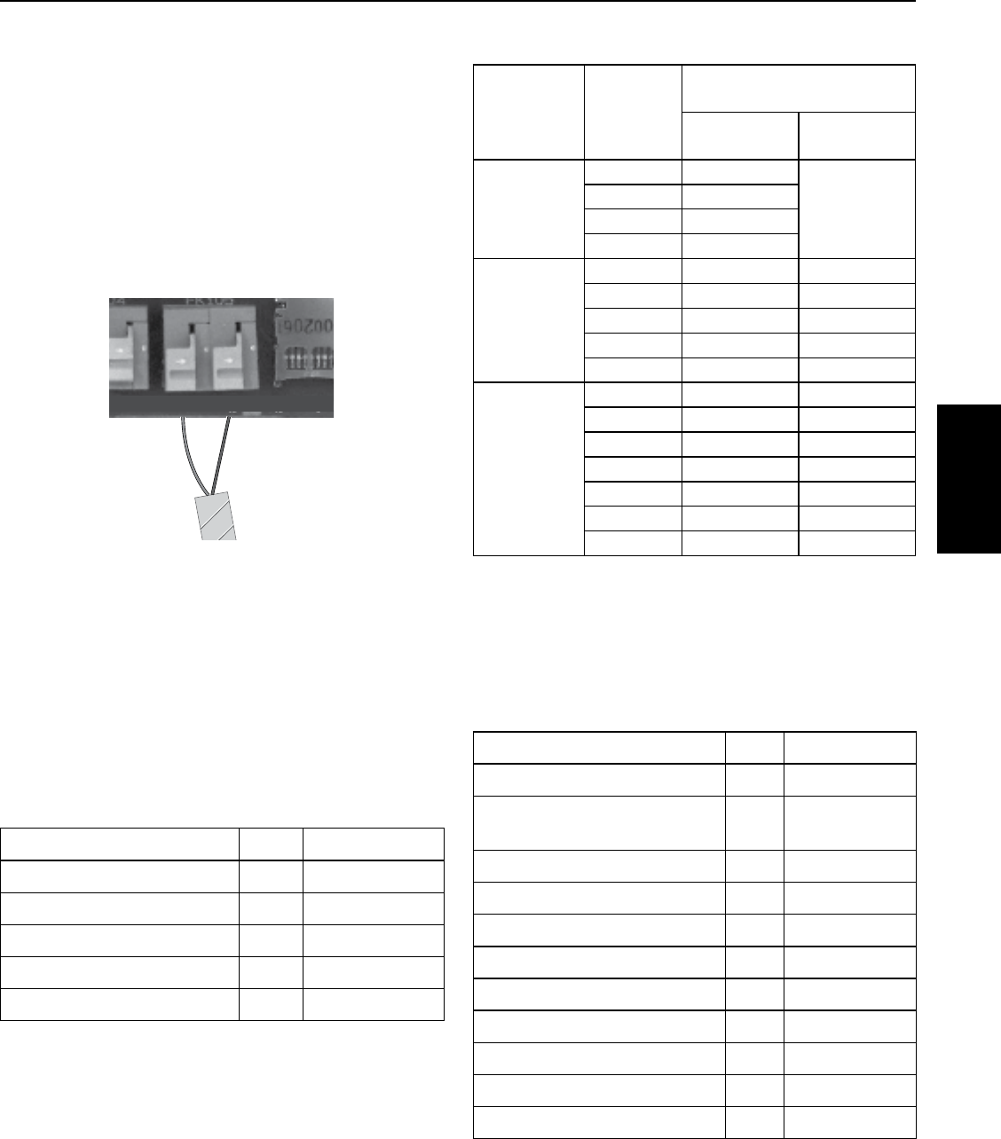
63
RS-485 Communications
RS-485 is a US-based telecommunications
standard for binary serial communications
between devices. It is the protocol, or set of
specifications, that needs to be followed to allow
devices that implement the standard to speak
to each other. A fully compliant RS-485 port is
included in the Pentek Intellidrive system to
permit serial connections among more than two
devices on an RS-485 compliant network. Figure
19 shows two-wire connection to the Drive.
Lightning/Surge Protection
Lightning arrestors or other surge suppressing
devices can be used with this product. MOV(Metal
Oxide Varistor), SOV(Silicon Oxide Varistor).
Accessories
Part Description Qty Part Number
Alternating Control Panel 1 VFD-ALT
Moisture Sensor 1 VFD-WS
Surge Protection Kits 1 VFD-SGA
300 PSI Transducer 1 U17-2000
Flow Switch 1 U17-1999
Retrofit Applications
When retrofitting an installation with the Pentek
Intellidrive, most of the preceding text can be
applied. As a convenience, the recommended
Service Factor Amps for non-Pentek® motors is
provided in Table 11. Always verify Service Factor
Amp values from current manufacturer literature.
Table 11 - Service Factor Amps @ 230V
Motor Type HP
Service Factor Rating,
in Amps
CentriPro
®
¹Franklin
Electric
®
²
2-Wire
1/2 4.7
N/A
3/4 6.4
1 9.1
1-1/2 11.0
CS/CR 3-Wire
1/2 4.9 4.3
3/4 6.3 5.7
1 7.2 7.1
1-1/2 11.1 11.5
2 12.2 13.2
3-Phase
1/2 2.9 2.9
3/4 3.9 3.8
1 4.7 4.7
1-1/2 6.1 5.9
2 7.6 8.1
3 10.1 10.9
5 17.5 17.8
¹ CentriPro SFA data was taken from the March 2012 BMAID
manual on 4/2012.
² Franklin Electric SFA data was taken from the 7/2011 Franklin
Electric AIM manual on 4/2012.
NOTICE The Pentek Intellidrive will not operate
Franklin Electric 2-wire motors.
Repair Parts
Part Description Qty Part Number
Input Terminal Block Connector 1 PID-CON2
Output Terminal Block
Connector 1 PID-CON3
Cooling Fan 1 PID-FAN-R
Pressure Transducer 1 U17-1561-R
10’ Transducer Cable 1 U18-1593
25’ Transducer Cable* 1 U18-1594
50’ Transducer Cable* 1 U18-1595
100’ Transducer Cable* 1 U18-1596
150’ Transducer Cable* 1 U18-1597
200’ Transducer Cable* 1 U18-1598
Keypad 1 PID-HMI-R
* Purchase Separately
6544 0412
01+ 01- I1+ I1- I2+ I2- V+ V- AI+ AI- P N SD CARD
Figure 19 - Example RS-485 Connection
SECTION 8: Pentek Intellidrive™ Variable Frequency Drives
8.7 Wiring Sizing, Repair Parts,
Specifications
PENTEK
INTELLIDRIVE
CentriPro® is a registered trademark of Fluid Handling LLC.
Franklin Electric® is a registered trademark of Franklin Electric Co. Inc.
All other brand or product names are trademarks or registered trademarks of Pentair Ltd.

64
Fault Possible Causes Solution
Over Current
Shorted output Check for any shorts in motor cables.
Locked rotor Check for debris in pump.
Damaged wire insulation Check motor wire insulation with a megger.
Over Voltage
Internal Drive short With power to Drive off, measure outputs with
ohmmeter to detect short.
Power cycling on and off Check for a generator or switching on input
line.
High line voltage Measure incoming line voltage to Drive;
should be between 190V and 265V.
Under Voltage
Low line voltage
Temporary loss of power Check for local power outage.
Excessive load current Check motor is correctly sized for the
application.
Loss of a motor phase Check correct voltage is present on all motor
leads.
Power was removed from
Drive
Check correct voltage is present on all input
lines.
Cannot Start Motor
Exceeding Service Factor
Amps
Check Service Factor Amps entered are
correct.
Check pump and motor are correct.
No Service Factor Amps value
entered
Check Service Factor Amps entered and are
correct.
There is an open (connection)
in motor wires Check resistance of all motor wires is correct.
Locked rotor Pull pump check for debris in pump.
Dry Run
Operation at open discharge
May need to reduce Dry Run Sensitivity
pressure or apply back pressure on
transducer.
Drive cannot read transducer
signal
Check linearity of transducer, as it may be
damaged. See Troubleshooting Guide for
more information.
Possible leak Check for pipe break or large leak.
Dry running pump Check water level in well.
Ground Fault
Ground wire shorted to motor
phase
Check the ground wire for short to motor
phase wire or check insulation integrity with a
megger.
Long motor cable length
If motor cable length is more than 1000 ft
a reactor or filter may be needed to limit
capacitance between motor wires.
System Not Grounded Ungrounded Drive Ground Detect parameter can be disabled, but
will reactivate after 72 hours.
*For additional Troubleshooting information, please visit www.sta-rite.com/resources/images/16455.pdf for a downloadable guide.
SECTION 8: Pentek Intellidrive™ Variable Frequency Drives
8.8 Troubleshooting

65
Fault Possible Causes Solution
Open Transducer
Intermittent connection Check all transducer wires are securely
connected or for damaged cable insulation.
Open Connection
Check for proper wiring of all transducer
wires and verify cable connector securely
attached to transducer.
Drive cannot read transducer
signal
Check electrical system for ground loops or
no ground connection.
Transducer wires crossed Check red is in AI+ and black is in AI-.
Possible failed transducer
Check linearity of transducer; see
Troubleshooting Guide for more
information.
Shorted Transducer
Short in transducer wires Check for shorted transducer wire or
damaged insulation.
Possible failed transducer
Check linearity of transducer; see
Troubleshooting Guide for more
information.
Over Temperature Excessive heating in drive
Check ambient temperature is not above
50°C (122°F).
Check for inoperable or unobstructed fan.
Check vents are not obstructed.
Excessive Runtime
Leak detected Check for leaks in pipe system.
Application calls for long run
times
Extend Excessive Runtime Hours limitation.
Disable Excessive Runtime Fault.
Internal Fault Internal voltages are out of
range
Drive will auto reset and attempt to clear
fault. Fault Reset can be pressed to
clear fault as well. Then try to operate
pump. If fault continues Drive may need
replacement.
Hardware Fault Internal hardware failure
Fault Reset can be pressed to clear fault.
Then try to operate pump. If fault continues
Drive may need replacement.
External Fault
The external device detected
fault condition and closed the
I1 or I2 input
Check external device.
Must press Fault Reset to clear.
Low Amps
Under-sized pump Increase Minimum Speed to 35 Hz.
Low current draw from pump
Thermal protector open in
motor (3 wire) Wait 20 minutes then restart pump.
Missing motor phase Check all motor connections at the Drive.
SECTION 8: Pentek Intellidrive™ Variable Frequency Drives
PENTEK
INTELLIDRIVE
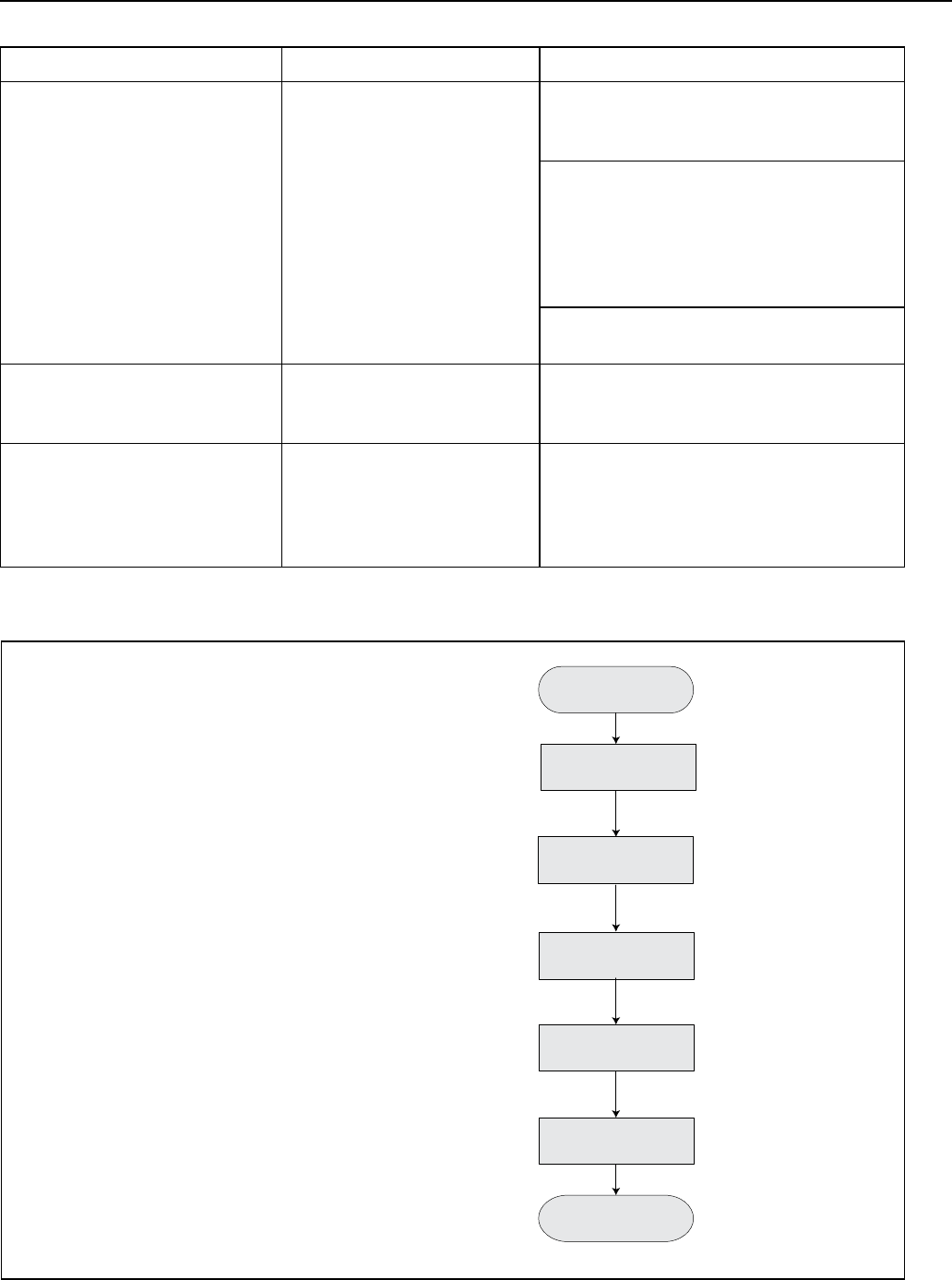
66
Warning Possible Causes Solution
Warning LED flashing
Ungrounded Drive, with
ground detection parameter
disabled (will operate for 72
hours and then fault).
Verify ground wire is connected on both
incoming voltage side and motor side of
Drive.
With the power disconnected, use an
ohmmeter to verify which pipe the Drive’s
transducer is connected to. Also verify
that the input ground wire is at the same
potential, e.g., has approximately the same
ohm reading.
Verify the input ground is connected all the
way back to electrical panel.
Jam Warning
Debris in pump stopping
motor from turning (locked
rotor).
Drive tries to free debris in pump by
reversing or pulsing motor.
Over Pressure Warning Pressure rising above Over
Pressure setting.
Drive stops and waits 1 minute, then
checks that pressure is below the Setpoint
pressure. Below it restarts, if not checks
again in another minute. Can increase over-
pressure value.
Drive Reset Procedure
Press Enter
6566 0612
Press Password
button
Press Enter to Edit
Change “No” to “Yes”
Confirm Reset
Press Main Menu
button
Press up or down arrow
until Reset appears
Enter Passwword
(Default is 7777)
Press Enter
Press Enter
Follow the keypress sequence
shown at right to test the Drive.
NOTICE In a domestic environment, this product
may cause radio interference which may require
supplementary mitigation measures.
Figure 20 - Drive Reset Procedure
SECTION 8: Pentek Intellidrive™ Variable Frequency Drives

67
Limited Warranty
Pentair warrants to the original consumer purchaser (“Purchaser” or “You”) of the products listed below, that they will be free from
defects in material and workmanship for the Warranty Period shown below.
Product Warranty Period
Water Systems Products — jet pumps, small centrifugal pumps,
submersible pumps and related accessories
whichever occurs first:
12 months from date of original installation,
18 months from date of manufacture
Pentek Intellidrive 12 months from date of original installation, or
18 months from date of manufacture
Pro-Source® Composite Tanks 5 years from date of original installation
Pro-Source Steel Pressure Tanks 5 years from date of original installation
Pro-Source Epoxy-Line Tanks 3 years from date of original installation
Sump/Sewage/Effluent Products 12 months from date of original installation, or
18 months from date of manufacture
Our warranty will not apply to any product that, in our sole judgment, has been subject to negligence, misapplication, improper
installation, or improper maintenance. Without limiting the foregoing, operating a three phase motor with single phase power
through a phase converter will void the warranty. Note also that three phase motors must be protected by three-leg, ambient
compensated, extra-quick trip overload relays of the recommended size or the warranty is void.
Your only remedy, and Pentair’s only duty, is that Pentair repair or replace defective products (at Pentair’s choice). You must pay all
labor and shipping charges associated with this warranty and must request warranty service through the installing dealer as soon as
a problem is discovered. No request for service will be accepted if received after the Warranty Period has expired. This warranty is
nottransferable.
PENTAIRISNOTLIABLEFORANYCONSEQUENTIAL,INCIDENTAL,ORCONTINGENTDAMAGESWHATSOEVER.
THE FOREGOING LIMITED WARRANTIES ARE EXCLUSIVE AND IN LIEU OF ALL OTHER EXPRESS AND IMPLIED WARRANTIES,
INCLUDING BUT NOT LIMITED TO IMPLIED WARRANTIES OF MERCHANTABILITY AND FITNESS FOR A PARTICULAR PURPOSE. THE
FOREGOING LIMITED WARRANTIES SHALL NOT EXTEND BEYOND THE DURATION PROVIDED HEREIN.
Some states do not allow the exclusion or limitation of incidental or consequential damages or limitations on how long an implied
warranty lasts, so the above limitations or exclusions may not apply to You. This warranty gives You specific legal rights and You may
also have other rights which vary from state to state.
This Limited Warranty is effective June 1, 2011 and replaces all undated warranties and warranties dated before June 1, 2011.
PENTAIR
293 Wright Street • Delavan, WI 53115
Phone (262) 728-5551 • Fax (262) 728-7323
SECTION 8: Pentek Intellidrive™ Variable Frequency Drives
8.9 Warranty
PENTEK
INTELLIDRIVE

68
9.1 Pentek® PPC-Series Drives
The Pentek Pump Controllers (PPC5 and PPC3 series)
are pre-jumpered and include the Pentek Assistant,
which simplifies programming and setup for constant
pressure applications. The Pentek Assistant sets various
parameters to Pentek defaults which are described in
this manual. The Pentek Assistant also prompts the user
for application-specific information.
For PPC3 and PPC5 troubleshooting, please refer to the
ABB ACS350 or ACS550 manual as appropriate.
9.2 PPC3 Series Specifications
Three-phase PPC3 drives can be operated on single
phase when the output amps are derated by 50%.
Table 9-1: Three-Phase/208-230V Output
Output
Amps
Input
Phase
Input
Voltage
Enclosure
Rating
(NEMA)
Catalog
Number
4.7
1
200-240 1
PPC3-1-4A7-1
6.7 PPC3-1-6A7-1
7.5 PPC3-1-7A5-1
9.8 PPC3-1-9A8-1
4.7
3
PPC3-2-4A7-1
6.7 PPC3-2-6A7-1
7.5 PPC3-2-7A5-1
9.8 PPC3-2-9A8-1
17.6 PPC3-2-17A6-1
24.6 PPC3-2-24A6-1
31.0 PPC3-2-31A0-1
46.2 PPC3-2-46A2-1
Table 9-2: Three-Phase/380-460V Output
Output
Amps
Input
Phase
Input
Voltage
Enclosure
Rating
(NEMA)
Catalog
Number
2.4
3 380-480 1
PPC3-4-2A4-1
3.3 PPC3-4-3A3-1
4.1 PPC3-4-4A1-1
5.6 PPC3-4-5A6-1
8.8 PPC3-4-8A8-1
12.5 PPC3-4-12A5-1
15.6 PPC3-4-15A6-1
23.1 PPC3-4-23A1-1
31.0 PPC3-4-31A0-1
38.0 PPC3-4-38A0-1
44.0 PPC3-4-44A0-1
NOTICE: For detailed specifications see users manual.
9.3 PPC5 Series Specifications
Table 9-3: Three-Phase/208-230V Output
Output
Amps
Input
Phase
Input
Voltage
Enclosure
Rating
(NEMA)
Catalog
Number
4.6
3 208-240
1 PPC5-2-4A6-1
12 PPC5-2-4A6-12
6.6 1 PPC5-2-6A6-1
12 PPC5-2-6A6-12
7.5 1 PPC5-2-7A5-1
12 PPC5-2-7A5-12
11.8 1 PPC5-2-11A-1
12 PPC5-2-11A-12
16.7 1 PPC5-2-16A-1
12 PPC5-2-16A-12
24.2 1 PPC5-2-24A-1
12 PPC5-2-24A-12
30.8 1 PPC5-2-30A-1
12 PPC5-2-30A-12
46.2 1 PPC5-2-46A-1
12 PPC5-2-46A-12
59.4 1 PPC5-2-59A-1
12 PPC5-2-59A-12
74.8 1 PPC5-2-74A-1
12 PPC5-2-74A-12
88.0 1 PPC5-2-88A-1
12 PPC5-2-88A-12
114 1 PPC5-2-114A-1
12 PPC5-2-114A-12
143
1
PPC5-2-143A-1
178 PPC5-2-178A-1
221 PPC5-2-221A-1
248 PPC5-2-248A-1
NOTICE: For detailed specifications see users manual.
For single phase input, derate the output amps by 50%.
SECTION 9: PPC Series 50/60 Hz Variable Frequency Drives

69
PPC Series
VFD
Table 9-4: 3-Phase/380-460V Output
Output
Amps
Input
Phase
Input
Voltage
Enclosure
Rating
(NEMA)
Catalog
Number
3.3
3 400-480
1 PPC5-4-3A3-1
12 PPC5-4-3A3-12
4.1 1 PPC5-4-4A1-1
12 PPC5-4-4A1-12
6.9 1 PPC5-4-6A9-1
12 PPC5-4-6A9-12
8.8 1 PPC5-4-8A8-1
12 PPC5-4-8A8-12
11.9 1 PPC5-4-11A-1
12 PPC5-4-11A-12
15.4 1 PPC5-4-15A-1
12 PPC5-4-15A-12
23 1 PPC5-4-23A-1
12 PPC5-4-23A-12
31 1 PPC5-4-31A-1
12 PPC5-4-31A-12
38 1 PPC5-4-38A-1
12 PPC5-4-38A-12
44 1 PPC5-4-44A-1
12 PPC5-4-44A-12
59 1 PPC5-4-59A-1
12 PPC5-4-59A-12
72 1 PPC5-4-72A-1
12 PPC5-4-72A-12
77 1 PPC5-4-77A-1
12 PPC5-4-77A-12
96 1 PPC5-4-96A-1
12 PPC5-4-96A-12
124
1
PPC5-4-124A-1
157 PPC5-4-157A-1
180 PPC5-4-180A-1
195 PPC5-4-196A-1
245 PPC5-4-245A-1
Table 9-5: 3-Phase/575V Output
Output
Amps
Input
Phase
Input
Voltage
Enclosure
Rating
(NEMA)
Catalog
Number
2.7
3 575
1 PPC5-5-2A7-1
12 PPC5-5-2A7-12
3.9 1 PPC5-5-3A9-1
12 PPC5-5-3A9-12
6.1 1 PPC5-5-6A1-1
12 PPC5-5-6A1-12
91 PPC5-5-9A0-1
12 PPC5-5-9A0-12
11 1 PPC5-5-11A-1
12 PPC5-5-11A-12
17 1 PPC5-5-17A-1
12 PPC5-5-17A-12
22 1 PPC5-5-22A-1
12 PPC5-5-22A-12
27 1 PPC5-5-27A-1
12 PPC5-5-27A-12
32 1 PPC5-5-32A-1
12 PPC5-5-32A-12
41 1 PPC5-5-41A-1
12 PPC5-5-41A-12
52 1 PPC5-5-52A-1
12 PPC5-5-52A-12
62 1 PPC5-5-62A-1
12 PPC5-5-62A-12
77 1 PPC5-5-77A-1
12 PPC5-5-77A-12
99 1 PPC5-5-99A-1
12 PPC5-5-99A-12
125 1 PPC5-5-125A-1
12 PPC5-5-125A-12
144 1 PPC5-5-144A-1
12 PPC5-5-144A-12
SECTION 9: PPC Series 50/60 Hz Variable Frequency Drives
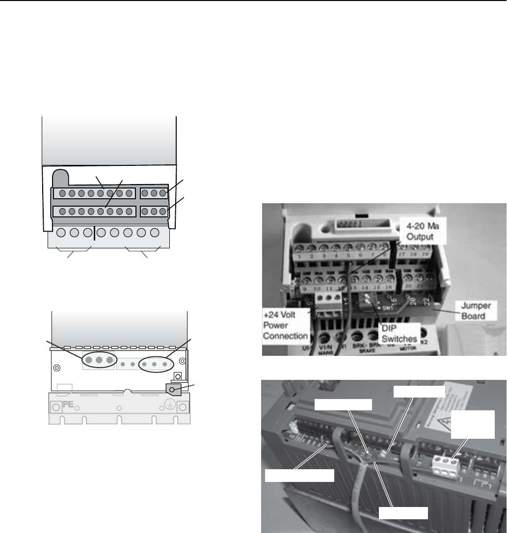
70
9.4 Wiring Connections
Three phase input power is connected to U1, V1, and W1.
If single phase input is used connect to U1 and W1. The
neutral and ground leads must be connected to drive
terminal PE. Motor leads are connected to U2, V2, and
W2. The motor ground must be connected to terminal
GND. For detailed instructions, see Owner’s Manual.
9.5 Transducer Connection
The Pentek® Assistant defaults to a 4-20mA transducer
connected to AI2. The transducer is used to provide
pressure feedback to the drive. Transducers offered
by Pentek have either a red or brown power lead. The
red or brown lead should be connected to the +24V
powerconnection.
Transducers offered by Pentek have either a blue or black
output lead. The blue or black lead should be connected
to terminal 5. The Pentek U17-1286R transducer utilizes
shielded cable. The bare lead may be covered with green
shrink-wrap tubing. The bare lead is cable shielding, and
should be connected to terminal 1. The translucent lead
is unused, and should be tied off andinsulated.
Figure 9-3 PPC3 Transducer Connection.
4 - 20 ma Output
Jumper Board
Power Lead
DIP Switches
+24 volt
Power
Connection
Figure 9-4 PPC5 Transducer Connection.
U1/L V1-N W1 BRKBRK U2 V2 W2
Digital Output
5405 0506
Relay Output
Digital Inputs
Analog I/O
Output to Motor
U2, V2, W2
Line Input
U1, V1, W1
Figure 9-1 Typical Connections to PPC3
Power
Output
to Motor
U2, V2, W2
Line Input
U1, V1, W1
Ground
5406 0506
Figure 9-2 Typical Connections to PPC5
SECTION 9: PPC Series 50/60 Hz Variable Frequency Drives

71
9.6.1 Description of Information Required
by the Pentek Assistant
9905 Motor Nom Voltage: This is the nominal voltage
stated on the motor nameplate. If the motor is rated
for operation at multiple voltages, select the voltage
nearest the utility voltage. Ensure the motor connections
correspond to the voltage selected.
9906 Motor Nom Current: This is the nominal current
found on the motor nameplate. Do not use service
factoramps.
9907 Motor Nom Freq: This is the nominal frequency
found on the motor nameplate.
9908 Motor Nominal Speed: This is the nominal speed
found on the motor nameplate. Use the number on the
motor nameplate. Do not enter 3600, 1800, etc.
9909 Motor Nom Power: This is the nominal horsepower
found on the motor nameplate. Do not include service
factor unless the service factor is greater than 1.15.
2001 Min Speed (Required for Subs only): This is the
minimum speed the motor is allowed to run. This
minimum is set to prevent damage to the motor thrust
bearings. Refer to motor literature to determine setting.
4011 Internal Setpoint: This is the pressure that the
system will maintain.
4009 100% Value: This is the full scale reading of the
transducer. The 100% Value of a 200PSI transducer
is200PSI.
4023 PID Sleep Level: Operation below this rpm will
cause the drive to stop. Must never be below the shut-off
head RPM.
4025 Wake-Up Dev: This is the pressure drop that will
trigger the drive to restart. For example, if the set point is
60 PSI and the Wake-Up Deviation is 10 PSI, the drive will
restart at 50 PSI.
Parameter Code Pentek Code
1002 Ext2 Commands Keypad
1102 EXT1/EXT2 Sel EXT2
1301 Minimum AI1 20%
1601 Run Enable Not Sel
1805 DO Signal Superv1 Over
1806 DO On Delay 10 Seconds (Above Ground)
1806 DO On Delay 60 Seconds (Submersible)
1807 DO Off Delay 2 sec
2001 Minimum Speed 0 (Above Ground)
2001 Minimum Speed User Defined (Submersible)
2002 Maximum Speed Sync
2202 Accel Time 1 5 sec (Above Ground)
2202 Accel Time 1 1 sec(Submersible)
3001 AI<Min Fault
3003 External Fault 1 DI5
3006 Mot Therm Time 500 sec (Above Ground)
3006 Mot Therm Time 350 sec (Submersible)
3007 Mot Load Curve 100% (Above Ground)
3007 Mot Load Curve 112% (Submersible)
3013 Underload Function Fault
3014 Underload Time 10 sec
3022 AI2 Fault Limi 10%
3201 Superv 1 Param Output Freq
3202 SuperV 1 Lim Lo per 9907
3203 SuperV 1 Lim Hi per 9907
Parameter Code Pentek Code
3401 Signal 1 Param Current
3405 Output 1 Unit A
3408 Signal 2 Param Speed
3412 Output 2 Unit RPM
3415 Signal 3 Param PID 1 FBK
3419 Output 3 Unit PSI
4001 Gain 1.0
4002 Integration Time 1.0
4006 Units PSI
4010 Set Point Sel Internal
4022 Sleep Selection Internal
4024 PID Sleep Delta 10 sec
4027 PID Param Set DI3
4101 Gain 1.0
4102 Integration Time 1.0 Sec
4106 Units PSI
4109 100% value Per 4009
4110 Set Point Sel Internal
4111 Internal Setpoint Per 4011
4122 Sleep Selection Internal
4123 PID Sleep Level Per 4023
4124 PID Sleep Delay 10 sec
4125 Wake-Up Deviation Per 4025
9.6 Pentek® Assistant
Table 9-6: PPC3 Parameters Changed Relative to PID Control Defaults
SECTION 9: PPC Series 50/60 Hz Variable Frequency Drives
PPC Series
VFD

72
9.6.2 Mounting and Installation
Startup the Pentek Assistant
Apply power to the unit, and follow the steps in section
9.6.3 after the Drive’s screen is lit.
9.6.3 Using the Pentek Assistant
Apply power to the unit and follow the steps in Section
9.6.4 for changing operation parameters, use the steps
below to run the Pentek Assistant.
1. Use the MENU key to access the Menu List.
2. Select Assistants
3. Select Pentek Assistant.
4. Follow the screen instructions to configure the
system.
Table 9-7: PPC5 Parameters Changed Relative to PID Control Defaults
SECTION 9: PPC Series 50/60 Hz Variable Frequency Drives
Parameter Code Pentek® Code
1002 EXT2 Commands 8-Keypad
1102 EXT1/EXT2 SEL EXT2
1301 Minimum AI1 20%
1401 RELAY OUTPUT 1 SUPERV1 OVER
1404 RO 1 ON DELAY 10 S (above ground)
60 S (submersible)
1405 RO 1 OFF DELAY 2 S
1601 Run Enable Not SeL
1605 USER PAR SET CHG 3-DI3
2001 Minimum Speed User defined (above ground)
0 (submersible)
2002 MAXIMUM SPEED SYNC
2202 ACCELER TIME 15 SEC (above ground)
1 SEC (submersible)
3001 AI<MIN FUNCTION 1-FAULT
3003 EXTERNAL FAULT 1 1-DI6
3004 EXTERNAL FAULT 2 5-DI5
3006 MOT THERM TIME 500 SEC (above ground)
350 SEC (submersible)
3007 MOT LOAD CURVE 100% (above ground)
112% (submersible)
3013 UNDERLOAD FUNC 1-FAULT
3014 UNDERLOAD TIME 10S
3022 AI2 FAULT LIMIT 10%
3201 SUPERV 1 PARAM 103-OUTPUTFREQ
3202 SUPERV 1 LIM LO 60
3203 SUPERV 1 LIM HI 60
3401 SIGNAL 1 PARAM 104-CURRENT
Parameter Code Pentek Code
3402 SIGNAL 1 MIN 0
3404 OUTPUT 1 DSP FORM 5-+0.0
3405 OUTPUT 1 UNIT 1 – AMPS
3408 SIGNAL 2 PARAM 102-SPEED
3411 OUTPUT 2 DSP FORM 4-+0
3412 OUTPUT 2 UNIT 7 – RPM
3415 SIGNAL 3 PARAMETER 128-PID 1 SETPNT
3418 OUTPUT 3 DSP FORM 1 - ± 0.0
3419 OUTPUT 3 UNIT 25 – PSI
4001 GAIN 1.0
4002 INTEGRATION TIME 2.0
4006 UNIT 25 – PSI
4010 SET POINT SEL 0 – KEYPAD
4011 INTERNAL SETPOINT USER DEFINED
4016 ACT1 INPUT 1-AI2
4017 ACT2 INPUT 1-AI2
4022 SLEEP SELECTION 7 – INT
4024 PID SLEEP DELAY 10 SEC
4027 PID 1 PARAM SET 3-DI3
4102 INTEGRATION TIME 1.0S
4106 UNIT 25-PSI
4109 100% Value per 4009
4110 SET POINT SEL 19-INTERNAL
4111 INTERNAL SETPOINT PER 4011
4122 SLEEP SELECTION 7-INT
4123 PID SLEEP LEVEL per 4023
4124 PID SLEEP DELAY 10SEC
4125 WAKE-UP DEV per 4025
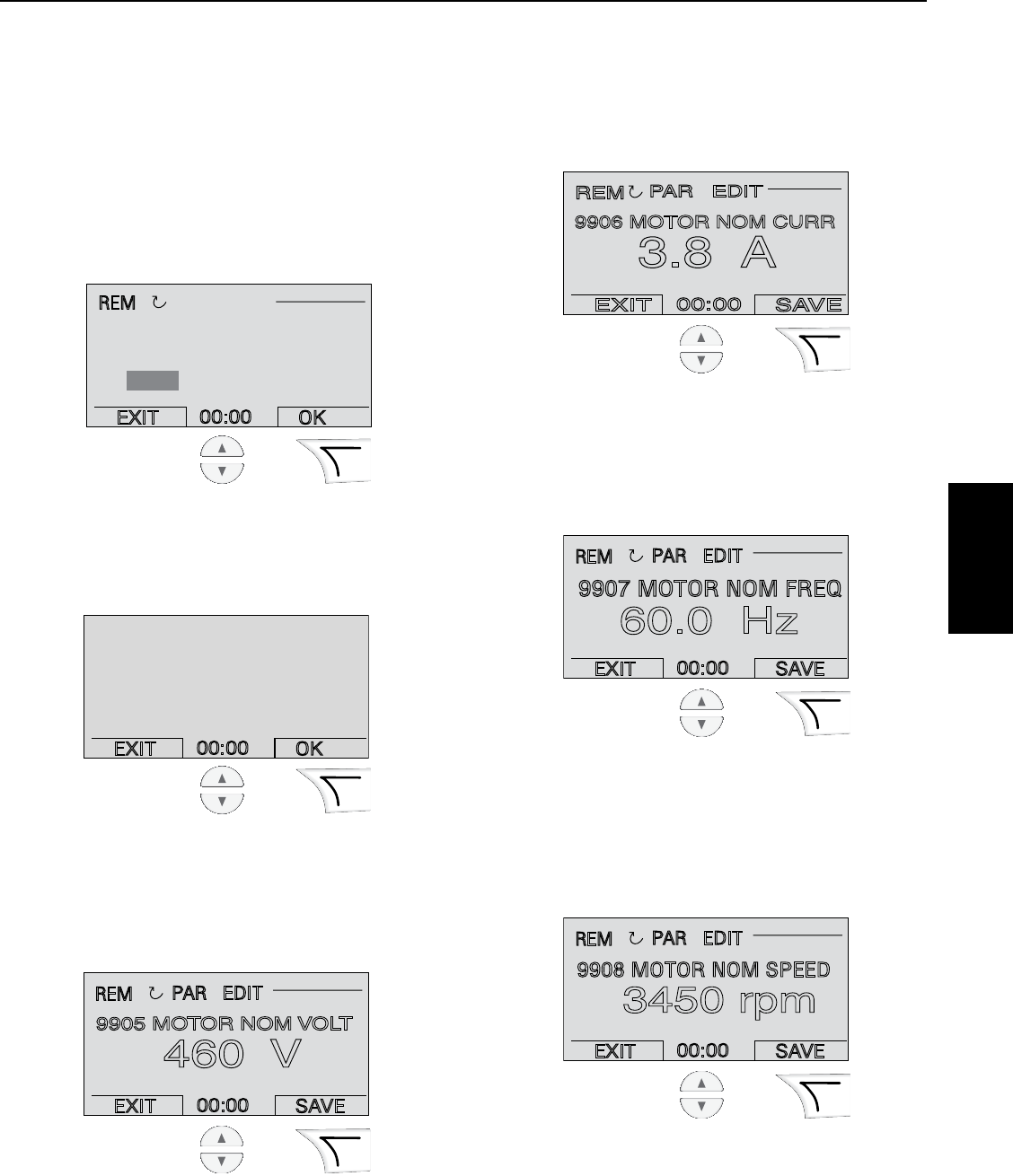
73
9.6.4 Step By Step Programming
Instructions
STEP 1
Initial Startup Panel Display
Upon initial drive power-up the installer will be prompted
to run the Pentek® Assistant. Scroll to YES and then
select OK. Wait while the program loads. On subsequent
startups, the Pentek Assistant can be found in the
ASSISTANTS menu.
STEP 2
Motor Selection Screen
Scroll to select the type installation and then press OK.
STEP 3
Motor Voltage Screen
The screen shows motor voltage. Scroll to select the
correct voltage for your motor as stated on the motor
nameplate. This sample shows 460 volts. Press SAVE.
STEP 4
Motor Current Screen
Enter the motor current from the motor nameplate
(not maximum amps). Scroll to select the current and
pressSAVE unless it is a submersible (more than 1.15).
STEP 5
Motor Frequency Screen
Enter the motor frequency (Hz) from the motor
nameplate. Scroll to select the frequency and select
SAVE.
STEP 6
Motor Speed Screen
Enter the motor speed (RPM) from the motor nameplate.
Scroll to select the speed and press SAVE. The sample
here shows 3450 RPM.
EXIT 00:00 SAVE
REM
PAR EDIT
460 V
9905 MOTOR NOM VOLT
EXIT 00:00 SAVE
REM
PAR EDIT
3.8 A
9906 MOTOR NOM CURR
EXIT 00:00 SAVE
REM
PAR EDIT
60.0 Hz
9907 MOTOR NOM FREQ
EXIT 00:00 SAVE
REM
PAR EDIT
3450 rpm
9908 MOTOR NOM SPEED
EXIT 00:00 OK
Please Select Mtr Type
Above Ground
Submersible
EXIT 00:00 OK
REM
CHOICE
Do you want to run
the PENTEK
assistant?
Ye s
No
SECTION 9: PPC Series 50/60 Hz Variable Frequency Drives
PPC Series
VFD
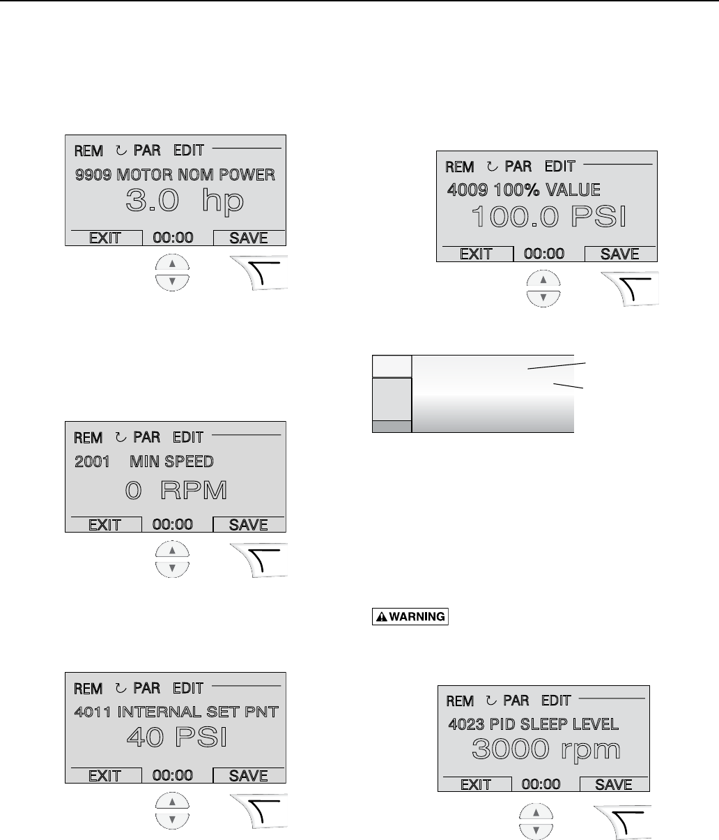
74
STEP 7
Motor Horsepower Screen
Enter the motor horsepower (HP) from the motor
nameplate. Scroll to select the horsepower and press
SAVE. The sample here shows 3.0 HP.
STEP 8
For Submersible Pumps Only
Enter the minimum speed allowed by the motor vendor
(consult motor literature). This is to prevent motor
bearingdamage.
STEP 9
Scroll To Select Constant Pressure Point
Example shows 40 PSI.
STEP 10
Transducer 100% Value
Enter the transducer’s full range value which should
be stated on the transducer body. Scroll to select the
pressure and then press SAVE. The sample here shows
100 PSI.
NOTICE: DO NOT choose maximum pressure.
STEP 11
PID Sleep Level Screen
Enter the PID sleep level. This is a motor speed setting.
If the motor speed falls below this RPM, the PID sleep
function will be enabled. This is a Drive-assigned value.
For additional information, refer to the PPC5 Users
Manual. Scroll to select the speed and then press SAVE.
The sample here shows 3000 RPM.
Burn Hazard. If the sleep level is set too
low, the pump my run without flow. This can boil water
inside the pump, causing dangerously high pressure
andtemperature.
EXIT 00:00 SAVE
REM
PAR EDIT
3.0 hp
9909 MOTOR NOM POWER
EXIT 00:00 SAVE
REM
PAR EDIT
0 RPM
2001 MIN SPEED
EXIT 00:00 SAVE
REM
PAR EDIT
40 PSI
4011 INTERNAL SET PNT
range: 0... 10 bar / 145 psi
max. pressure: 25 bar / 362.5 psi
UE: 80...330 VDC
OUT: 4...20mA Load <(N-8V) /0.02A
Use this Full Range Value
Do NOT use Maximum Pressure
EXIT 00:00 SAVE
REM
PAR EDIT
100.0 PSI
4009 100% VALUE
EXIT 00:00 SAVE
REM
PAR EDIT
3000 rpm
4023 PID SLEEP LEVEL
SECTION 9: PPC Series 50/60 Hz Variable Frequency Drives
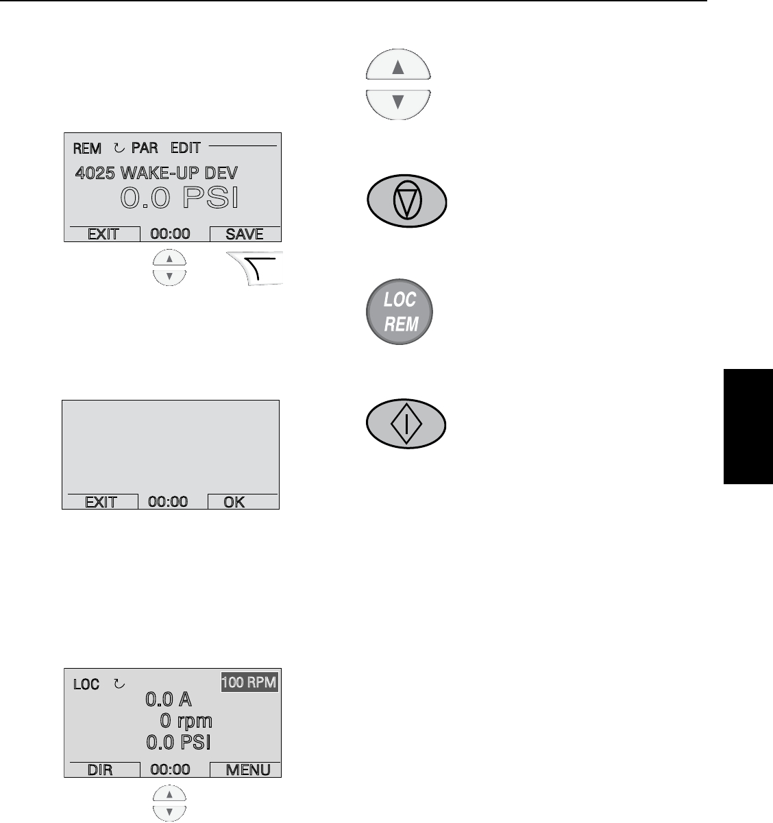
75
STEP 12
Wake up Deviation Screen
Enter the wake-up deviation. This is the amount pressure
drops (PSI) below the pressure set point before the drive
restarts. This sample is waiting to be set and shows
0 PSI.
STEP 13
Assistant Compete
This ends setup of the Pentek® Assistant. The following
steps complete the setup of the pump system.
STEP 14
Check Motor Rotation
Press the Local/Remote button to change to local control.
Check above-ground motors by viewing shaft rotation.
For submersible (3-phase) motors, start and check
performance. Reverse any two power leads and check
again. The lead arrangement with best performance is
correct.
STEP 15
Check For System Harmonics
While the pump is running, scroll motor
speed up to check for harmonics. Verify
that harmonics do not exist above the PID
sleeplevel.
STEP 16
Stop The Pump
Press the STOP button.
STEP 17
Change To Remote Operation
Press the Loc / Rem button to change to
remote control.
STEP 18
Test System Setup
Press start to operate the pump. Test
system to ensure proper system response
and sleep function. Adjust group 40
parameters as needed.
NOTICE: The upper left hand corner of the display shows
whether the drive is in local or remote control. In LOC
mode the drive holds a constant speed which can be
adjusted using the up/down buttons. The speed which will
be held is in the upper right hand corner. In REM mode
the drives holds a constant pressure.
TIP: For common parameters and menu items, use the
Help key ? to display descriptions.
If you encounter Alarms or Faults, use the Help key or
refer to the Diagnostic section of the ABB User’s Manual.
SECTION 9: PPC Series 50/60 Hz Variable Frequency Drives
EXIT 00:00 SAVE
REM
PAR EDIT
0.0 PSI
4025 WAKE-UP DEV
DIR 00:00 MENU
LOC
100 RPM
0.0 A
0 rpm
0.0 PSI
EXIT
00:00
OK
PENTEK Assistant
Complete
PPC Series
VFD

76
9.7 Timer Function
The Pentek® PPC Series controller includes four timer
functions. Each timer function can include up to four daily
/ weekly start and stop times.
The following example show the parameter changes
required to use PID Set 2 on Monday, Wednesday, and
Friday from 8:00AM to 10:00AM.
Parameter Setting
3601 – Timers Enable .................. 7 – Enabled
3602 – Start Time 1 ....................... 8:00AM
3603 – Stop Time 1....................... 10:00AM
3604 – Start Day 1 ...................... 1-Monday
3605 – Stop Day 1 ....................... 1-Monday
3606 – Start Time 2 ....................... 8:00AM
3607 – Stop Time 2....................... 10:00AM
3608 – Start Day 2 ................... 3-Wednesday
3609 – Stop Day 2 ................... 3 – Wednesday
3610 – Start Time 3 ....................... 8:00AM
3611 – Stop Time 3....................... 10:00AM
3612 – Start Day 3 ........................ 5-Friday
3612 – Stop Day 3 ......................... 5-Friday
3626 – Timer Func1SCR ............ 7 = P3 +P2 + P1
4027 – PID 1 Param Set......... 8 = Timer Function 1
9.8 Helpful Hints
Alarm 2025 upon startup
This is a normal alarm, and occurs whenever motor data
is changed. The alarm shows for about 15 seconds while
the drive performs a motor calibration.
Fault 14 External Fault 1
External fault 1 is triggered when the VFD’s output
frequency exceeds motor nameplate frequency for more
than 10 seconds. The ON delay parameter controls
the time delay for this fault. If the system includes a
large tank, or requires more time to reach the setpoint,
increase parameter 1404 (PPC5) or 1806 (PPC3).
This fault is designed to protect against loss of prime,
broken shafts, etc. To disable this fault, adjust parameter
2002 Maximum speed, to the motor nameplate rpm.
Sleep
The Pentek drive monitors pump speed to determine
demand. The pump is shut off when the rpm goes below
parameter 4023: PID Sleep Level. Always set parameter
4023 high enough to trigger sleep mode during low
demand conditions. Note that the shut-off head at
parameter 4023: RPM, must be higher than the pressure
set-point.
The pressure setpoint can be determined by slowly
closing the discharge valve to confirm that the RPM
decreases to a level that triggers the sleep mode. The
discharge head can also be found by using the BEC2
program on the BEC2.net website.
Systems that use small tanks, or have a flat performance
curve, may cycle rapidly at intermediate flows. Correct
this by increasing Parameter 4024: PID Sleep Delay.
DO NOT increase parameter 4024 to a level that will
cause the pump to run with no demand. The water in the
pump can overheat.
Sleep Options
Other devices such as flow or float switches can be used
to trigger sleep mode. Parameter 4022 determines the
method to trigger sleep mode. These options can be used
for pump up, pump down, and other on/off applications.
Multiple Systems / Setpoints
The Pentek PPC Series Controller includes (2)
independent process control sets (groups 40 and 41).
Group 41 parameters can be selected using Digital Input
(DI3). When first set-up, groups 40 and 41 are identical.
A set can be changed later with parameters for a
secondprocess.
Constant Flow
After running the Pentek Assistant, the drive can be
configured for constant flow by adjusting parameters
4006: Units, and 4009: 100% Value.
Constant Flow Example 1:
Using a 4-20ma velocity meter with a range of
0 to 10 ft/sec. We want the display to be ft/sec.
Set 4006 to ft/sec
Set 4009 to 10
Constant Flow Example 2:
Same setup as example 1, but we have a 4” pipe and want
the display to be gpm.
Set 4006 to gpm
Set 4009 to 393 (this is the flow in a 4” pipe which results
in a 10 ft/sec velocity).
Constant Flow Example 3:
Using a 4-20ma flow meter with a range of 0 to 100 gpm.
We want the display to be gpm.
Set 4006 to gpm
Set 4009 to 100
SECTION 9: PPC Series 50/60 Hz Variable Frequency Drives
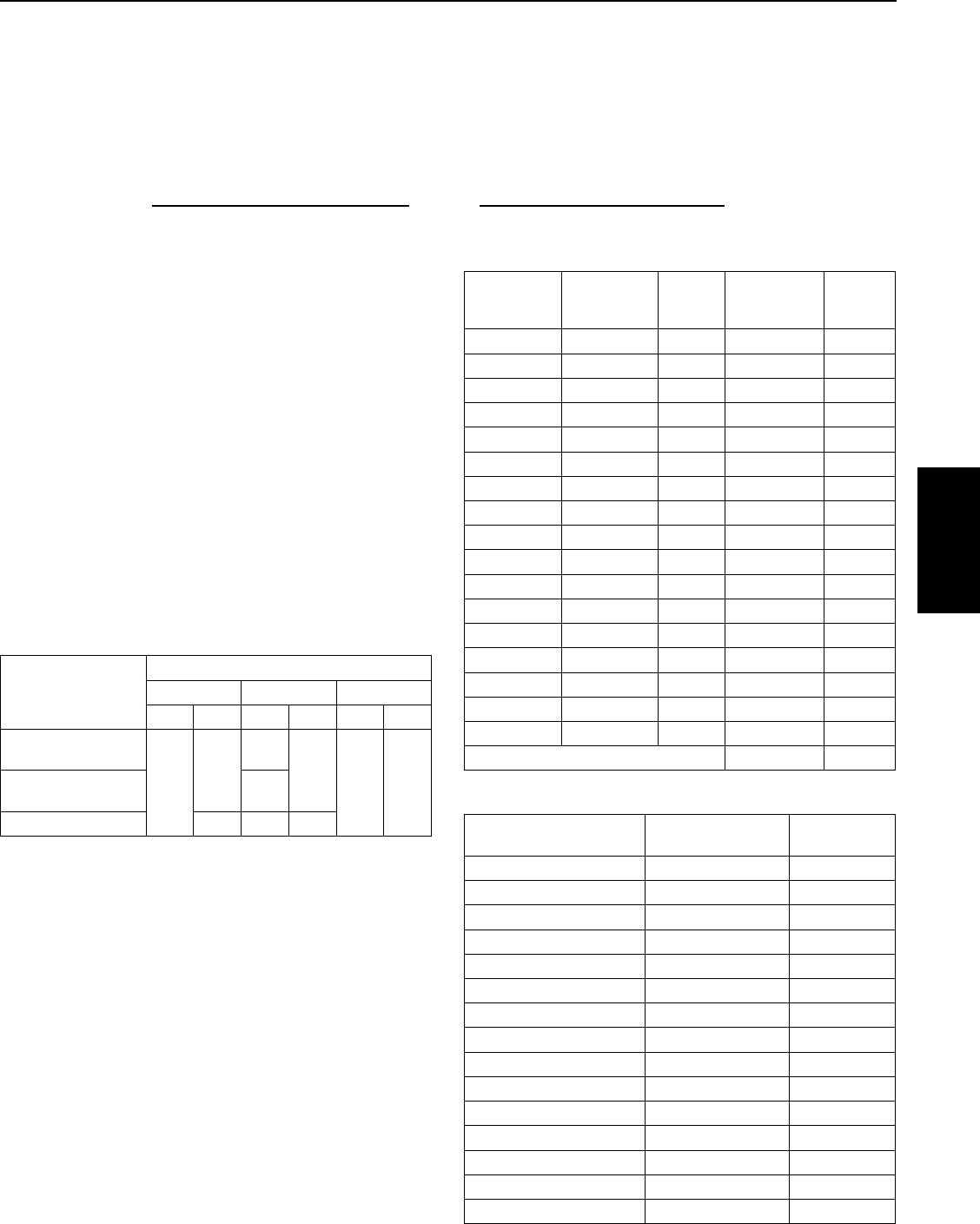
77
9.10 Reactors And Filters
Variable frequency drives produce voltage spikes that are
a function of voltage rise-time and length of motor cable.
In extreme cases peak voltage may exceed three times
the nominal operating voltage.
Reactors
A reactor is a resistance and inductance device that
reduces voltage spikes. It does this by both increasing the
voltage rise-time and improving the impedance match of
the cable and motor.
Filters
A filter combines a reactor with a capacitor network. The
capacitors absorb a portion of the voltage spikes. This
further reduces the peak voltage seen at the motor.
When to Use a Reactor or Filter
The chart below is a general guideline when choosing
between using a filter or reactor.
Motor Type
Lead Length
up to 50’ 50’ to 150’ 150’ to 1000’
230 V 460V 230V 460V 230V 460V
NEMA Above-Ground
Std. Efficiency
--
R
RF FNEMA Above-Ground
Premium Efficiency -
Submersible R R F
R = Reactor F = Filter
The following list indicates a greater need for filters
andreactors:
• Longmotorleadsareused
• Standardefficiencyorsubmersiblemotorsareused.
• Thecostofreplacingthemotorisprohibitive.
• Usingasubmersiblemotorwithavoltagerating
greater than 230V.
• Thequalityand/orageofthemotorisunknown.
• Conditionofwiringand/orpowerqualityisunknown.
9.9 PPC3 and PPC5 Tank Sizing
These instructions are only for systems that require
tanks. Pressure tanks are generally required to maintain
system pressure during periods of low or no demand.
Tank pre-charge must be less than the pressure set point
– wake up deviation.
Tank can be sized using Boyle’s law (V1 x P1 = V2 x P2).
Units are in gallons and PSI.
Typically tanks are sized for approximately 20% of pump
capacity. For example, a 150 gpm pump typically requires
30 gallon total tank size.
Total Tank Size x (Precharge+14.7) __ Total Tank Size x (Precharge+14.7)
(Setpoint+14.7 – Wake Up Deviation) (Setpoint+14.7)
Drawdown =
Reactors
Open Design
230 or 460V
Model
NEMA1
230 or 460V
Model
Rated
Amps
NEMA 1
575 V
Model
Rated
Amps
KDRA1P KDRA1PC1 3.4 KDRA31PC1 2.7
DDRA2P KDRA2PC1 4.8 KDRA35PC1 3.9
KDRA3P KDRA3PC1 7.6 KDRA33PC1 6.1
KDRA4P KDRA4PC1 11 KDRA34PC1 9
KDRB1P KDRB1PC1 14 KDRA36PC1 11
KDRD1P KDRD1PC2 21 KDRD31PC2 17
KDRD2P KDRD2PC2 27 KDRD32PC2 22
KDRD3P KDRD3PC2 34 KDRD35PC2 27
KDRD4P KDRD4PC2 40 KDRD33PC2 32
KDRC1P KDRC1PC2 52 KDRD34PC2 41
KDRF1P KDRF1PC3 65 KDRC31PC2 52
KDRF2P KDRF2PC3 77 KDRF31PC3 62
KDRF3P KDRF3PC4 96 KDRF32PC3 77
KDRH1P KDRH1PC4 124 KDRF33PC4 99
KDRI1P KDRI1PC4 156 KDRH31PC4 125
KDRI2P KDRI2PC4 180 KDRI31PC4 144
KDRG1P KDRG1PC4 240 KDRI32PC4 192
KDRG31PC4 242
Filters
NEMA 1, 230, 460 or 575 V
Model
NEMA 1, CUL Listed
Model Rated Amps
KLC4BE KLCUL4BE 4
KLC6BE KLCUL6BE 6
KLC8BE KLCUL8BE 8
KLC12BE KLCUL12BE 12
KLC16BE KLCUL16BE 16
KLC25BE KLCUL25BE 25
KLC35BE KLCUL35BE 35
KLC45BE KLCUL45BE 45
KLC55BE KLCUL55BE 55
KLC80BE KLCUL80BE 80
KLC110BE KLCUL110BE 110
KLC130BE KLCUL130BE 130
KLC160BE KLCUL160BE 160
KLC200BE KLCUL200BE 200
KLC250BE KLCUL250BE 250
SECTION 9: PPC Series 50/60 Hz Variable Frequency Drives
PPC Series
VFD
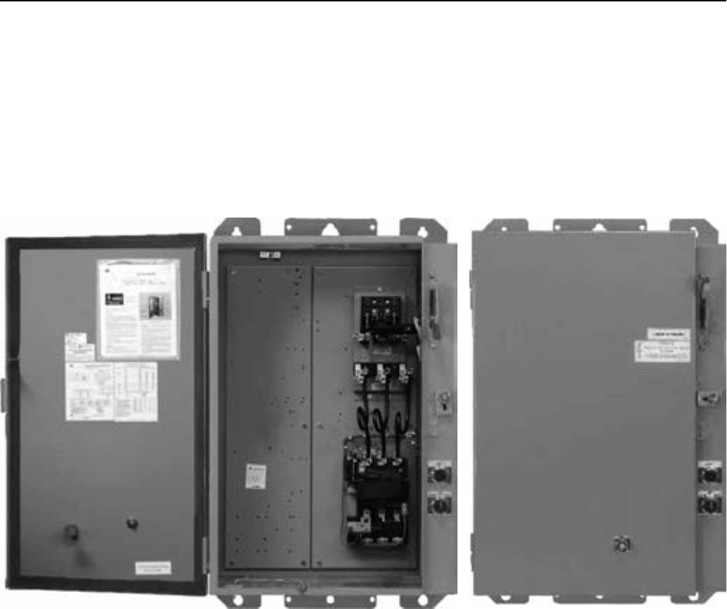
78
SECTION 10: PPX NEMA Pump Panels
10.1 Description
The PPX series of pump control panels consist of a
manually operated fusible disconnect switch and a
magnetic contactor with a solid-state overload housed
in a NEMA enclosure. The fusible disconnect switch
provides motor branch short-circuit protection. The
contactor is proven in field applications where wide
voltage fluctuations may occur. The overload relays
provide motor overload protection.
The rainproof enclosure allows all routine operations to
be performed from the outside without opening the door.
The fusible disconnect switch handle is mechanically
interlocked with the enclosure door to prevent opening
the door before the handle is moved to the OFF position.
For better access during repair or inspection, the cover
may be removed by lifting the door upward and outward.
A latch is provided to prop the door open on windy days.
The overload relay incorporates a dial for field adjustment
of tripping current.
Install in conformance with National Electrical Code
and all local codes. Branch circuit protection must be
provided.
These controllers have all components arranged for easy
access from the front. The circuits are relatively simple
and circuit components are selected for trouble-free
operation. Periodically, depending on the environment
and duty, the panel should be inspected and cleaned.
Inspect all devices for loose bolts and nuts.
Figure 10-1: Typical NEMA Enclosure

79
PPX Panels
SECTION 10: PPX NEMA Pump Panels
Table 10-1: NEMA Full-voltage Combination Starters
NEMA size Disconnect Amps Max Total Amps Overload Current Range (Amps) Part Number
208V
1 30 13.5 6.5-13.5 PPX-1A-13-30R
27 13-27 PPX-1A-27-30R
2 60 50 25-50 PPX-2A-50-60R
3 100 70 35-70 PPX-3A-70-100R
100 65-135 PPX-3A-135-100R
4 200 135 65-135 PPX-4A-135-200R
230-240V
1 30 13.5 6.5-13.5 PPX-1B-13-30R
27 13-27 PPX-1B-27-30R
2 60 50 25-50 PPX-2B-50-60R
3 100 70 35-70 PPX-3B-70-100R
100 65-135 PPX-3B-135-100R
460-480V
1 30 13.5 6.5-13.5 PPX-1C-13-30R
27 13-27 PPX-1C-27-30R
2 60 50 25-50 PPX-2C-50-60R
3 100 70 35-70 PPX-3C-70-100R
100 65-135 PPX-3C-135-200R
4 200 135 65-135 PPX-4C-135-200R
5 400 270 130-270 PPX-5C-270-400R
575-600V
1 30 13.5 6.5-13.5 PPX-1D-13-30R
13-27 PPX-1D-27-30R
2 60 50 25-70 PPX-2D-50-60R
3 100 70 35-70 PPX-3D-70-100R
100 65-135 PPX-3D-135-100R
4 200 135 65-135 PPX-4D-135-200R
5 400 270 130-270 PPX-5D-270-400R
Includes complete starter with fusible switch, H-O-A selector switch, START push button, and electronic overload
protection in Type 3R enclosure. Fuses are not included.
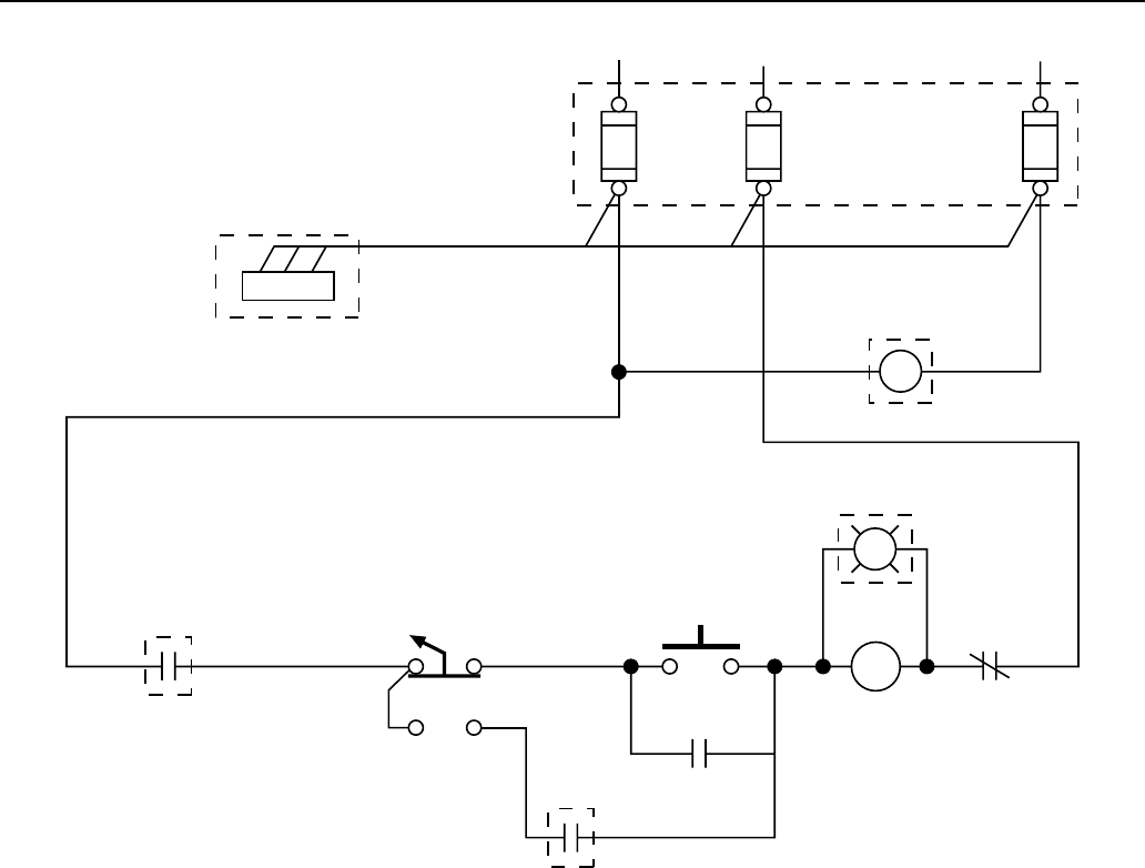
80
SECTION 10: PPX NEMA Pump Panels
Figure 10-2: Typical PPX NEMA Size 1 through 5 Schematic
Diagram
Key:
M = Motor Contactor
IL = Indicating Light
OL = Overload
CCF = Control Circuit Fusing
PFR = Phase Failure Relay
UVR = Undervoltage Relay
Dotted Line Box = If Used
PFR L1B
UVR
L3B
CCF
L3AL2AL1A
START PB
AUTO
SEL SW
6405 0311
OFF
HAND
UVR or PFR
REMOTE
DEVICE
OL
IL
9
5
M
M
321
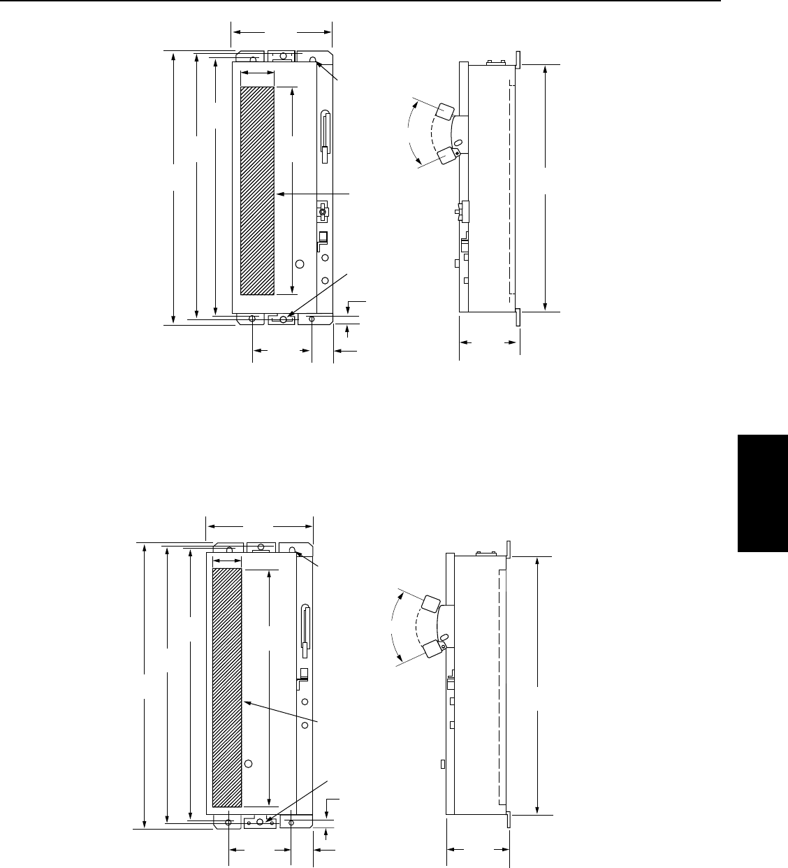
81
SECTION 10: PPX NEMA Pump Panels
Outlines, Dimensions in in. (mm), and Weights (lbs) - For Estimating Only
Figure 10-4: NEMA Sizes 3 and 4 Wide-Type Enclosures ; 195 lbs .
Figure 10-3: NEMA Sizes 1 and 2 Wide-Type Enclosures ; 85 lbs. (Size 1), 90 lbs. (Size 2)
6406 0311
30.4
(863.6)
32.32
(821.0)
32.25
(819.2)
9.00
(228.6)
4 POINT
MOUNTING
FOR 3/8”
BOLTS
SPACE
AVAILABLE FOR
MODIFICATIONS
2 POINT
MOUNTING
FOR 5/8” BOLTS
(IF USED)
1.19
(30.2)
2.25
(57.2)
16.0
(406.4)
20.94
(531.8)
ON
OFF
50O
29.25
(743.0)
7.00
(177.8)
27.50
(698.5)
SPACE
AVAILABLE FOR
MODIFICATIONS
4 POINT
MOUNTING
FOR 3/8”
BOLTS
2 POINT
MOUNTING
FOR 5/8” BOLTS
(IF USED)
1.19
(30.2)
2.25
(57.2)
20.0
(508.0)
9.00
(228.6)
24.81
(630.2)
47.38
(1203.5)
45.75
(1162.0)
44.75
(1136.0)
ON
OFF
42.38
(1076.3)
8.63
(219.1)
50O
35.0
(889.0)
6407 0311
PPX Panels

82
SECTION 9: PPX NEMA Pump Panels
6408 0311
52.0
(1320.8)
20.94
(531.8)
4 POINT
MOUNTING
FOR 3/8”
BOLTS
2 POINT
MOUNTING
FOR 5/8” BOLTS
(IF USED)
SPACE
AVAILABLE FOR
MODIFICATIONS
50.38
(1279.7)
49.38
(1254.3)
22.0
(558.8)
1.19
(30.2)
4.19
(106.4)
13.50
(342.9)
17.00
(431.8)
ON
OFF
47.0
(1193.8)
10.0
(254.0)
50O
Outlines, Dimensions in in. (mm), and Weights (lbs) - For Estimating Only
Figure 10-5 NEMA Size 5 Wide-Type Enclosures; 285 lbs

83
SMC Panels
60 Hz
SECTION 11: Submersible Motor Controls
11.1 How it Works
Submersible Motor Controls act as an above ground
control system for you submersible motor. They provide
easy access to the “brains” of your motor, so you can
monitor, adjust and perform maintenance without
removing the motor.
There are three main groups of motor controls. Each of
these controls has a slightly different function, although
all serve the main purpose of providing control for the
motor.
Capacitor Start / Induction Run (CSIR)
A CSIR control uses a starting capacitor and a switch.
When voltage is first applied, the switch is closed and
the start capacitor is in the circuit. This provides extra
torque to bring the motor up to speed. The switch is often
referred to as a potential relay. The relay’s coil senses
voltage across the windings. When the windings get
close to full speed, they magnetize the coil and physically
breaks the connection to the start windings. This takes
not only the start windings out of the circuit, but the
starting capacitor as well. The motor then runs on the
main winding alone.
Capacitor Start / Capacitor Run (CSCR)
A CSCR control functions very similar to a CSIR control
except that in addition to the starting capacitor, it also
uses a running capacitor. This allows the start winding
to act as an auxiliary winding during operation. This
smooths out operation of the motor and provides greater
efficiency and a reduction in vibration and noise.
Plus Series Controls
The Pentek® PLUS series controls combine a CSCR
design and a control circuit to provide not only starting
power to the motor, but a switch to turn the control
on and off. The switch takes the form of a magnetic
contactor that uses a coil that physically closes the
contacts when energized. The contactor allows the
installer to use a pressure switch with a lower current
rating, since it is not switching the full amperage of the
motor.
11.2 Specifications
All Pentek Submersible Motor Controls are rated for
Indoor or Outdoor use and employ NEMA 3R enclosures.
They are rain-tight and resistant to weathering
andcorrosion.
The controls are rated for operation in temperatures
up to 50° C (122° F). DO NOT locate the control box in
directsunlight.
The terminals can accept up to #4 AWG copper wire rated
for at least 75° C. Internal wiring conforms to appliance
wiring standards UL 1015 which is resistant to acids, oils,
alkalies, moisture and fungus.
Pentek Submersible Motor controls are agency
recognized and tested to rigorous safety standards.
For specific ratings of individual components please see
the repair parts portion of the manual.
11.3 Mounting and Installation
• Mountthecontrolboxestoasecurebacking.
• Mountcontrolsverticalandplumb.
• InordertomaintainNEMA3R,plugall
unusedopenings.
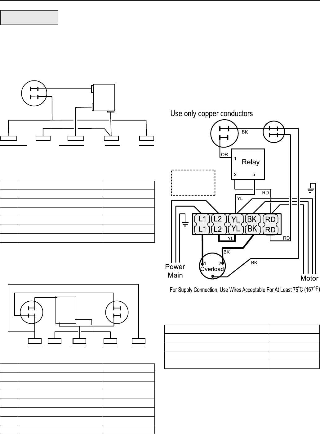
84
NOTICE: Attach installation wiring to the top of the
terminal strip. Schematics may show otherwise for
clarity.
1.5 HP Std
Start
Capacitor
Run
Capacitor
4776 0311
BL
3
Installation wiring
should be installed
into the top of the
terminal block
1-1/2 HP Capacitor Start, CapacitorRun
Model SMC-CR1521
60 Hz.
11.4 Wiring Connections and Replacement Parts
Start Capacitor
Relay
5 2
1
OR
YL
RD
BK
Line InMotor Leads
1/2 - 1 HP
Use only copper conductors
4773 0311
YStart (R) L2 L1Main (B)
1/2 to 1 HP Capacitor Start, InductionRun
Mo dels SMC-IR0511, SMC-IR0521, SMC-IR0721
andSMC-IR1021
Description Part Number
Overload Protector U17-1313-R
Relay U17-1592-R
Start Capacitor, 105 µF, 330v U17-1430-R
Run Capacitor, 10 µF, 370v U17-1438-R
HP Description Part Number
1/2 Start Capacitor, 43 µF, 270v U17-1422-R
3/4 Start Capacitor, 59 µF, 270v U17-1423-R
1Start Capacitor, 86 µF, 270v U17-1424-R
1/2 Run Capacitor, 15 µF, 370v U17-1419-R
3/4 Run Capacitor, 23 µF, 370v U17-1292-R
1Run Capacitor, 23 µF, 370v U17-1292-R
All Relay U17-1592-R
HP Description Part Number
1/2 Start Capacitor, 250 µF, 125v U17-1429-R
1/2 Start Capacitor, 59 µF, 270v U17-1423-R
3/4 Start Capacitor, 86 µF, 270v U17-1424-R
1Start Capacitor, 105 µF, 270v U17-1425-R
230V Relay U17-1592-R
115V Relay U17-1593-R
Relay
2
1
5
Start
Capacitor
Run
Capacitor
1/2 to 1 HP
Use only copper conductors
BK
BK
BK
OR
YL RD
RD
Line In
Motor Leads
L2
6402 0311
L1
Main (B)
Y
Start (R)
1/2 to 1 HP Capacitor Start, CapacitorRun
Models SMC-CR0521, SMC-CR0721, and SMC-CR1021
SECTION 11: Submersible Motor Controls
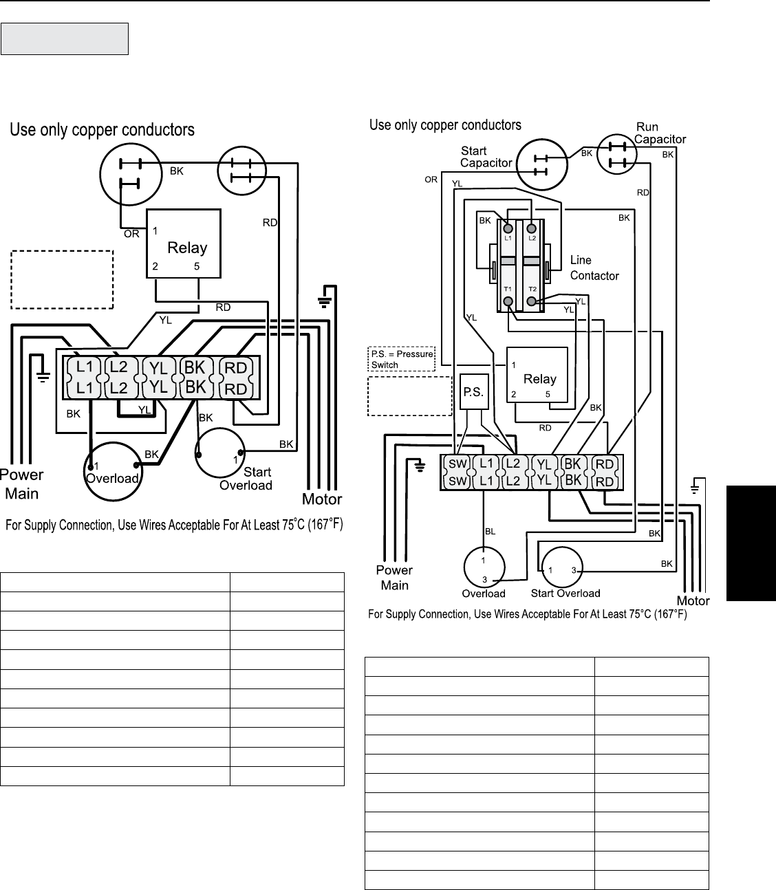
85
Description Part Number
Start Capacitor,105 µF, 330v, 2 HP U17-1430-R
Start Capacitor, 208 µF, 330v, 3 HP U17-1428-R
Run Capacitor, 20 µF, 370v, 2 HP U17-1440-R
Run Capacitor, 45 µF, 370v, 3 HP U17-1443-R
Main Overload Protector, 2 HP U17-1319-R
Main Overload Protector, 3 HP U17-1322-R
Start Overload Protector, 2 HP U17-1320-R
Start Overload Protector, 3 HP U17-1323-R
Relay - 2 HP U17-1592-R
Relay - 3 HP U17-1432-R
Magnetic Contactor P17-954-R
Description Part Number
Start Capacitor,105 µF, 330v, 2 HP U17-1430-R
Start Capacitor, 208 µF, 330v, 3 HP U17-1428-R
Run Capacitor, 20 µF, 370v, 2 HP U17-1440-R
Run Capacitor, 45 µF, 370v, 3 HP U17-1443-R
Main Overload Protector, 2 HP U17-1319-R
Main Overload Protector, 3 HP U17-1322-R
Start Overload Protector, 2 HP U17-1320-R
Start Overload Protector, 3 HP U17-1323-R
Relay - 2 HP U17-1592-R
Relay - 3 HP U17-1432-R
SECTION 11: Submersible Motor Controls
2 & 3 HP Std
Start
Capacitor
Run
Capacitor
5339 0311
BL
Installation wiring
should be installed
into the top of the
terminal block
33
2 and 3 HP Standard
Models SMC-CR2021 and SMC-CR3021
2 and 3 HP Plus
5341 0311
Attach Installation
wiring to top of
terminal block
2 and 3 HP Plus
Models SMC-CRP2021 and SMC-CRP3021
60 Hz.
SMC Panels
60 Hz
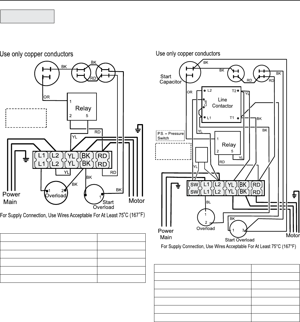
86
5 HP Std
3
Start
Capacitor Run Capacitors
5340 0311
BL
Attach Installation
wiring to top of
terminal block
5 HP Standard
Model SMC-CR5021
5 HP Plus
Run Capacitors
5342 0311
Attach Installation
wiring to top of
terminal block
P. S.
5 HP Plus
Model SMC-CRP5021
60 Hz.
Description Part Number
Start Capacitors, 270 µF, 330v U17-1437-R
Run Capacitor, (2) 40 µF, 370v U17-1442-R
Magnetic Contactor P17-953-R
Main Overload Protector U117-1456B-R
Start Overload Protector U17-1321-R
Relay U17-1432-R
Description Part Number
Start Capacitors, 270 µF, 330v U17-1437-R
Run Capacitor, 80 µF, 370v U17-1502-R
Main Overload Protector U117-1456A-R
Start Overload Protector U17-1321-R
Relay U17-1432-R
SECTION 11: Submersible Motor Controls

87
SECTION 12: Motor Protective Devices - 50/60 Hz
12.2 Specifications
Parameter SPP-111P SPP-111P-3RL SPP-231P SPP-233P SPP-235P-XX
1 Phase Line Voltage (±10%) 115 VAC 230 VAC
Load Range 1/3 - 1/2 HP
(.25 - .37 kW)
1/3 - 1 HP
(.33-.75 kW)
1/3 - 1 HP
(.25 - .75 kW)
1/3 - 3 HP
.25 - 2.24 kW)
5 - 15 HP
(3.73 - 11.19 kW)
Frequency 50-60 Hz
Power Consumption (Maximum) 5 W
Operating Temperature -40° to 158° F (-40° to +70° C)
Electrostatic Discharge (ESD) IEC 1000-4-2, Level 2, 4kV Contact, 6 kV Air
Output Contact Rating (SPST) 1/2 HP @ 115 VAC
(17 AMPS MAX)
1 HP @ 115 VAC
(17 AMPS MAX)
1 HP @ 240 VAC
(17 AMPS MAX)
3 HP @ 240 VAC
(17 AMPS MAX) 480 VA @ 240 VAC
Weight .63 lbs (.28 kg) 1.6 lbs (.73 kg)
w/enclosure .63 lbs (.28 kg) 1.6 lbs (.73 kg)
Enclosure None NEMA 3R None NEMA 3R w/ LENS
Current Transformer Ratio N/A N/A N/A N/A
SPP-235-75 – 50:5
SPP-235-100 - 75:5
SPP-235-150 -
100:5
Operating Points
Overload 125 % of Calibration Point
Underload (Dry Run) ~80% of Calibration Point
Overvoltage Trip Point 132.5 VAC 265 VAC
Undervoltage Trip Point 95 VAC 190 VAC
Nu mber of Restarts allowed in a 60sec.
Period before lockout (Rapid Cycle
Timer)
4
Trip Delay Time (Overload) 5s
Trip Delay Time (Dry Run) 2s
Restart Delay Time
Overvoltage/Undervoltage Delay 5s
Al l other faults (Dry Run Rec. Timer) 2-225 min
Terminal
Wire Gauge N/A 12-22
Maximum Torque 7 in-lbs
12.1 How They Work
Pentek® motor protectors are designed to protect single
phase pumps from dry run, dead head, jammed impeller,
and over & under voltage conditions.
A calibration adjustment allows the motor protector to
be calibrated to specific pumping applications, thereby
reducing the possibility of false or nuisance tripping. A
micro drive based voltage and current sensing circuit
monitors for power fluctuations, over-current, and under-
current conditions. When an abnormality, such as loss
of suction, is detected, the motor protector deactivates
its output relay and immediately disconnects the pump
motor. The motor protector then activates its user-
selectable “Restart Delay” (Dry run recovery) timer.
When the timer counts to zero or power is removed and
reapplied, the motor protector reactivates its output relay
and turns the pump back on.
An infrared LED communicates directly with a hand-held
diagnostics tool called the Informer (sold separately). The
Informer displays 16 parameters including calibration
point, trip point, running points, and last fault.
NOTICE: The use of flow restrictors or unusually high
head pressures at the time of calibration may interfere
with the detection of dead head conditions.
Motor Protection
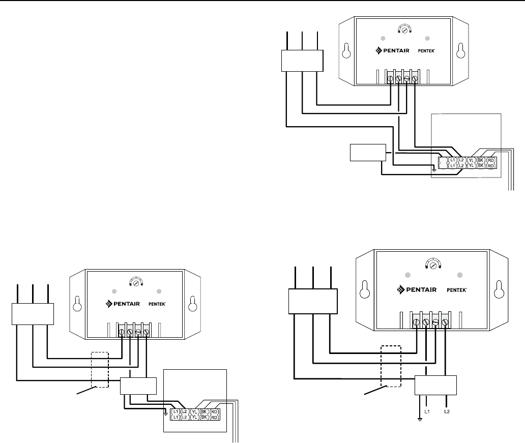
88
SECTION 12: Motor Protective Devices - 50/60 Hz
12.3 Mounting And Installation
Mount the Pentek® Motor Protector in a convenient
location in or near the motor control panel. If the location
is wet or dusty, then the Pentek Motor Protector should
be mounted in a NEMA 3R, 4, or 12 enclosure.
12.4 Wiring Connections
1. Connect one line from the fused disconnect to the
Motor protector’s “L1 IN” terminal. Run a wire from
the “L1 OUT” terminal to the other in-line controls
such as a pressure or float switch. See Figure 10-1.
2. Connect the other line from the fused disconnect to
Motor Protector “L2 IN” terminal. Run a wire from the
“L2 OUT” terminal to the other in-line controls such
as pressure or float switches. See Figure 12-1.
NOTICE: The Motor Protector may not detect a dead head
(blocked pipe) condition on applications where the pump
is undersized for a given motor or flow restrictors are
used on high stage pumps or low yield wells.
Calibration/Settings
NOTICE: Calibrate the Motor Protector during normal
pumping conditions.
1. Turn the RESTART DELAY / CALIBRATION adjustment
fully counter-clockwise to the “CAL.” position.
2. Apply power to the Motor Protector. The pump motor
should be running at this point.
3. The Motor Protector is being calibrated when the
CAL. LIGHT turns on (approximately 5 seconds).
Within 10seconds, proceed to step 4.
4. Set the RESTART DELAY / CALIBRATION adjustment
to the desired Restart Delay (Dry Well Recovery Time).
If you leave the RESTART DELAY / CALIBRATION
adjustment in the “CAL.” position, the unit will trip
off and stay off. Turn the adjustment out of the “CAL.”
position to start the pump.
Manual Reset Mode: If the RESTART DELAY /
CALIBRATION adjustment is set to “RESET”, the Motor
protector is in Manual Reset mode. After the Motor
Protector shuts down due to a voltage or load problem,
the RESTART DELAY / CALIBRATION adjustment must be
rotated out of the “RESET” position to restart the pump.
NOTICE: Any restart delay can be by-passed by rotating
the RESTART DELAY / CALIBRATION adjustment to
the “RESET” position and back to the desired Restart
Delaysetting.
Rapid Cycling Protection: Rapid cycling is defined as
more than four restarts in a 60 second period. The Motor
Protector will lockout upon detecting a rapid cycling
condition until power is removed and re-applied to the
L1 IN and L2 IN terminals. See Diagnostics Table for
instructions to diagnose a rapid cycling fault.
L1 OUT
L1 IN L2 IN L2 OUT
2
50
100
150
225
CALRESET
CAL
LIGHT
RUN
LIGHT
Submersible Pump Protector
GND
GND
L1
L1
L2
L2
Fused
Disconnect
4“ Plus 3-Wire
Control Box
Pressure
Switch
Motor
SW
SW
Figure 12-2: “Plus” Control Box Connection for
SPP233
L1 OUT
L1 IN L2 IN L2 OUT
2
50
100
150
225
CAL RESET
CAL
LIGHT
RUN
LIGHT
Submersible Pump Protector
GND
GND
L1
L1
L2
L2
Fused
Disconnect
Pressure
Switch
Alternate Pressure Switch
Location When Rapid Cycle
Protection is not needed
5204
Figure 12-3: 2-Wire Connection for SPP233
L1 OUT
L1 IN L2 IN L2 OUT
2
50
100
150
225
CAL RESET
CAL
LIGHT
RUN
LIGHT
Submersible Pump Protector
GND
GND
L1
L1
L2
L2
Fused
Disconnect
Standard 3-Wire
Control Box
1/3 to 3 HP
Pressure
Switch
M
o
t
o
r
Alternate Pressure Switch
Location When Rapid Cycle
Protection is not needed
5201
Figure 12-1: SPP233 Standard Control Box Connection

89
Troubleshooting
13.1 Pump And Motor Problem Analysis
Problem Possible Cause Check And Restore
Pump Won’t Start. No voltage (check
with voltmeter).
Typically will be no
startupnoise.
1. Main power supply off.
2. Blown fuse or tripped circuit breaker.
3. Wiring damage, loose connection.
4. Burnt contactor points.
Locked pump. 1. Check for sand in system.
2. Crooked well (submersible)
Overloads Trip. Low or high voltage. 1. Check with voltmeter. (±10% of nameplate voltage). Request
power company correct problem.
2. Determine if wire size is correct for voltage and amperage.
Hi gh ambient
temperature or direct
sunlight.
1. Improve cooling for motor and controls.
2. Use ambient compensated overloads.
In correct pump sizing –
mismatched motor.
1. Check pump (gpm) make sure near B.E.P. - “Best Efficiency
Point”.
2. Recheck pump and motor model numbers prior to installation.
Keep a written record.
High cycling rate. 1. Pressure control equipment malfunction.
2. Hole in piping system.
3. Pressure/storage tank failure.
Damaged motor control. Check components per troubleshooting.
Fu ses Blow or
Breaker Trips.
Short or Ground. 1. Fuses give superior protection and should be used in preference
to circuit breakers when possible.
2. Inspect wiring for visible signs of heat damage (discoloration,
damage to insulation).
3. Disconnect power and check with ohmmeter or megohmmeter
toground.
Improper sizing. Consult manufacturer’s information / sizing chart for proper size
and replace as required.
Lo w or No Water
Production.
No rotation. 1. Motor not turning (see “Pump won’t start” above.
2. Broken shaft coupling. Ammeter will show “low” amps.
Restriction in piping. 1. Check valve sticking.
2. Check valve installed backward.
3. Broken check valve poppet or flapper lodged in piping system
downstream.
Plugged inlet. 1. Intake screen encrusted with minerals.
2. Insufficient clearance between pump and well casing for high
capacity pump. Calculate intake velocity and limit to less than
5feet per second.
SECTION 13: Troubleshooting
90
SECTION 13: Troubleshooting
Pump And Motor Problem Analysis (Continued)
Problem Possible Cause Check And Restore
Lo w or no water
production
(continued)
Well drawdown. 1. Install air line upon reinstalling unit if not already present for
measuring depth with tire pump and gage.
2. Measure dynamic (drawdown) level with string or resistance
meter.
3. Select different pump if appropriate.
Well collapsed. 1. Unit is pumping dirty or sandy water.
2. Lift with pump hoist, check pull weight and resistance
Pump selection. 1. Recheck operating conditions by comparing to pump curve.
2. Operate within ±5 percentage points of efficiency from B.E.P.
Hole in well piping. 1. Listen for sucking sound at well head when pump shuts off.
2. Well pipe empties when submersible pump is pulled from well.
Wrong rotation. 1. Three phase motor - exchange any two of the three leads in the
three phase motor starter panel.
2. Single phase motor - recheck motor and control panel wiring
diagrams. Change wiring as appropriate.
3. Proper rotation for motors for sub. and centrifugal pumps with
CW rotation is CCW when looking at the shaft end of the motor.
4. Make a visual flow check or observe flow meter. Amperage is not
a reliable indicator of wrong rotation.
Improper sizing. Consult manufacturer’s performance charts or curves.
Ho le in distribution
piping.
1. Observe pressure loss with system shut off.
2. Look for wet spot or depression along pipe path.
Pu mp runs all the
time.
Drawdown. 1. Check for surging, irregular amperage readings with amprobe.
2. Look for bursts of air in water.
3. Listen for surging sounds in piping.
Control equipment. 1. Control equipment incorrectly selected or installed.
2. Welded electrical contact points.
3. Pressure switch supply pipe/tube plugged with rust/scale/ice.
Hazardous pressure and risk of explosion and
scalding. If pump is running continuously at no flow (with discharge
shut off), water may boil in pump and piping system. Under steam
pressure, pipes may rupture, blow off of fittings or blow out of pump
ports and scald anyone near.

91
SECTION 13: Troubleshooting
Pump And Motor Problem Analysis (Continued)
Problem Possible Cause Check And Restore
Pu mp runs all the
time (continued)
Pump wear. 1. Check amperage - generally lower unless severe bearing damage has
occurred.
2. Verification may require removal of pump for service and visual
inspection.
Electric shock. Gr ounded wiring
or motor.
1. PROCEED WITH CAUTION!
2. Remove rings and other jewelry from hands before working with live
power circuits.
3. Wear insulated boots and gloves.
4. Disconnect the power, check with ohmmeter.
5. Progressively check wire at each splice point (or obvious damage
point).
6. When ground disappears, the fault is behind the point of discovery.
7. Check motor leads to motor shell with cable splice removed to
determine if ground fault is in motor or supply cable.
Moisture. Protect motor, motor starter and control devices from condensation or
direct water spray.
Am meter reads high
on two leads, zero
on the 3rd.
Th ree phase
motor “single
phasing”.
1. One power lead is not live or online.
2. Check with local utility company to see if having problems.
3. Check local power installation for transformer problems.
4. Will not be able to observe this condition very long. Very destructive to
motor windings. Motor stator will soon be destroyed if single phasing
protection is not installed.
5. This problem usually requires a replacement motor.
6. Determine source, install or replace protective gear.
Ov erload trip –
ammeter reads high
on all leads.
Bi nding or
dragging.
1. High volume of sand or other abrasives in well. Check by observing
water output.
2. Severe damage to motor thrust bearing due to cavitation or abrasives.
Usually very noisy.
3. Damage to motor control system.
Po wer supply
problems.
1. Check with voltmeter while pump is running for ±10% voltage
variance.
2. Extreme grounding of motor or supply cable. Check with ohmmeter
ormegohmmeter.
3. Poor wiring connections. Check splice, and terminal screws for
looseness. Watch for discolored cable.
Troubleshooting
92
SECTION 13: Troubleshooting
13.2 Motor Troubleshooting Flow Charts
Troubleshooting Flow Chart
Follow the arrow from the symptom on the left, to the inspection in the middle box.
If the middle box describes to symptom, proceed to the box on the right for the solution.
Motor Does
Not Start
Contact power company if
voltage is incorrect.
No power or Incorrect Voltage.
Using voltmeter, check the line terminals.
Voltage must be +/- 10% of rated voltage.
YES
NO
Replace with proper fuse
or reset circuit breaker.
Fuse blown or circuit breakers tripped.
Check fuses for correct size. Check for
loose, dirty or corroded connections in fuse
holder. Check for tripped fuses.
YES
NO
Replace pressure switch.
Defective Pressure Switch.
Check voltage at contact points. Improper
contact of switch points can cause
lower voltage.
YES
NO
Correct faulty wiring or
connections.
Defective Wiring.
Check for loose or corroded connections.
Check motor lead terminals with voltmeter
for voltage.
Check resistance of the lines with an
ohmmeter (POWER OFF!)
YES
NO
Repair or replace pump
assembly.
Bound Pump.
Locked rotor condition can result from
misalignment between pump and motor,
or sand-bound pump. Amp readings will be
3 to 6 times higher than normal.
YES
93
SECTION 13: Troubleshooting
Troubleshooting Flow Chart (Continued)
Follow the arrow from the symptom on the left, to the inspection in the middle box.
If the middle box describes to symptom, proceed to the box on the right for the solution.
Motor Starts
Too Often Reset or replace switch.
Pressure switch.
Check pressure switch settings, and
examine for damage or defects. Is the
switch damaged or set wrong?
YES
NO
Replace check valve.
Check valve stuck open.
Damaged or defective check valve will
not hold pressure. Is water draining back
into the well?
YES
NO
Correct or replace air
system.
Waterlogged tank (air supply).
Check air charging system for proper
operation. Is there inadequate air in tank? YES
NO
Replace damaged pipes
or repair leaks.
Leak in System.
Check system for leaks. Are leaks found? YES
Motor Troubleshooting Flow Charts (continued)
Troubleshooting
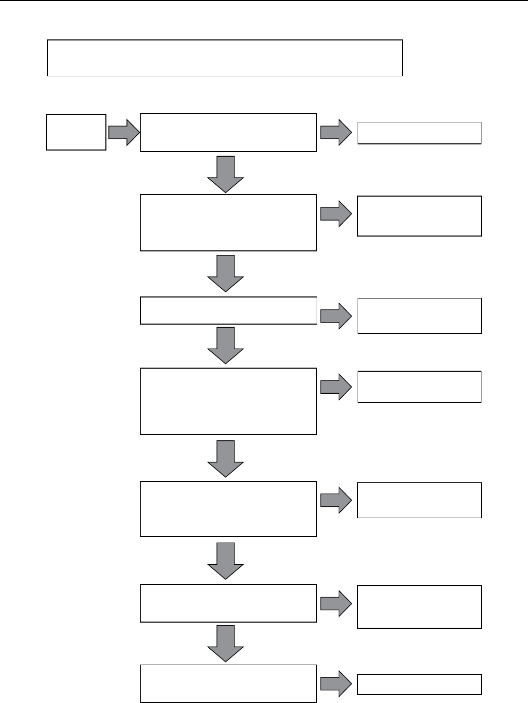
94
SECTION 13: Troubleshooting
Follow the arrow from the symptom on the left, to the inspection in the middle box.
If the middle box describes to symptom, proceed to the box on the right for the solution.
Motor runs
continuously Replace pressure switch
Pressure switch.
Are switch contacts “welded” in the
closed position, or set too high? YES
NO
Throttle pump output or
reset pump to lower level.
Do not lower into sand.
Low well level.
Pump may exceed well capacity. Shut off
pump, and wait for well to recover. Check
static and drawdown levels from well head.
Does water level recover to original level?
YES
NO
Pull pump and replace
or repair.
Worn pump.
Symptoms are similar to a leak in a down-
pipe, or low water level in the well. Reduce
pressure switch setting. If pump shuts off
worn parts may be at fault. Is sand found
in the tank?
YES
NO
Pull pump, replace or
repair damaged parts.
Loose or broken motor shaft.
Little or no water will be delivered if the
coupling between the motor and pump
shaft is loose. A jammed pumps may have
caused the motor shaft to shear off.
YES
NO
NO
Clean screen and reset at
less depth. May need to
clean the well.
Pump screen blocked.
Restricted flow may indicate a plugged
intake screen. Pump may be in mud / sand.
YES
NO
Replace check valve
Check valve stuck closed.
No water will flow past a check valve in the
closed position.
YES
Troubleshooting Flow Chart (Continued)
Replace damaged pipes
or repair leaks.
Leak in system.
Check system for leaks. Are leaks found? YES
Motor Troubleshooting Flow Charts (continued)
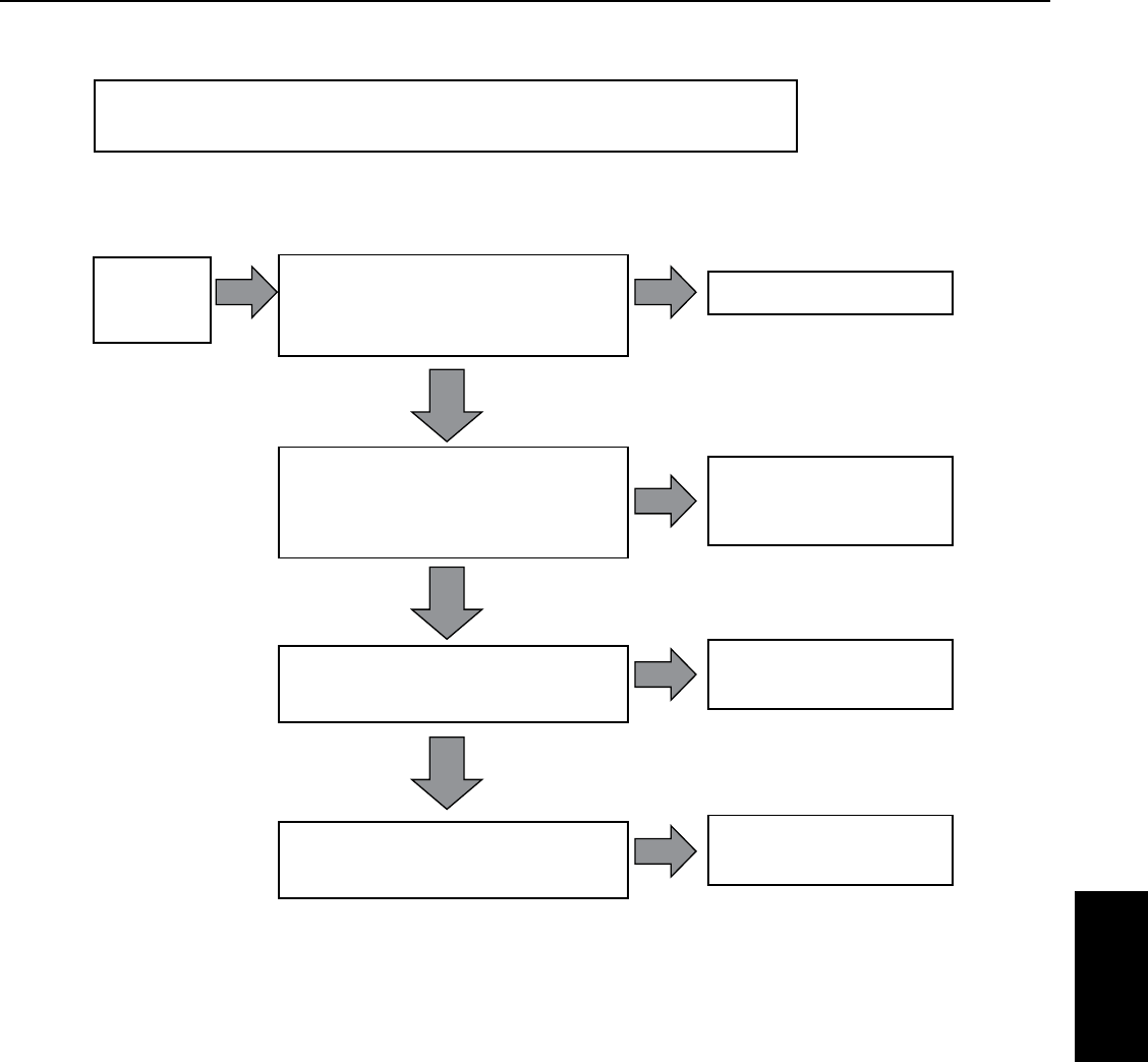
95
SECTION 13: Troubleshooting
Troubleshooting Flow Chart (Continued)
Follow the arrow from the symptom on the left, to the inspection in the middle box.
If the middle box describes to symptom, proceed to the box on the right for the solution.
Motor runs
but overload
protector trips
Contact power company.
Incorrect voltage
Using voltmeter, check the line terminals.
Is the voltage more than +/- 10% of
rated voltage?
YES
NO
Shade control box, provide
ventilation or move box
away from heat sorce.
Overheated protectors.
Direct sunlight or other heat source can
heat up the control box and cause
protectors to trip. Is control box in the
sunlight or hot to touch?
YES
NO
NO
Replace pump end
and / or motor.
Worn pump or motor.
Check motor running current. Is it higher
than nameplate amps?
YES
Replace wire with correct
size.
Incorrect wire size.
Check wire size and run-length with
wire size chart. Is it sized too small?
YES
Motor Troubleshooting Flow Charts (continued)
Troubleshooting

96
SECTION 13: Troubleshooting
13.3 Testing Submersible Motor
Insulation and Winding
Resistance
Insulation Resistance
1. Turn off power!
2. Set the ohmmeter to RX100K ohms.
3. Zero the ohmmeter.
4. Connect one lead to the metal drop pipe (or to ground
if the pipe is plastic).
5. Connect the other lead to any motor lead.
6. Check each power lead.
7. Compare results to the following table.
Resistance Indicates
20K ohm Damaged motor, possible result of lightning strike.
500K ohm Typical of older installed motor in well.
2 M ohm Newly installed motor
10 M ohm Used motor, measured outside of well
20 M ohm New motor without cable
Winding Resistance
1. Turn off power!
2. Set the ohmmeter to RX1 ohm range. For values over
10, use the RX10 ohm scale.
3. Zero the ohmmeter.
4. Compare results to resistance shown in motor
specifications table.
Three Phase Motors
Measure each line to each other (three readings).
Compare these to the line-to-line resistance shown in
motor specification table.
• Ifallleadsmeasurewithinthetablespecifications,
the leads and motor are okay.
• Ifaleadshowsahigherresistance,thenthereis
an open in the cable or winding. Check for secure
cableconnections.
• Ifaleadshowslowerresistance,thenthereisashort
circuit in the cable or winding.
Single Phase Motors: 3-wire
• Measurethemainwinding(blacktoyellow).
• Measurethestartwinding(redtoyellow).
• Comparethesereadingswiththemotor
specificationtable.
• Ifthereadingsvarywidely(somehigh,somelow),the
leads may be switched. Confirm that the cable colors
are correct.
Single Phase Motors: 2-wire
• Measuretheresistancebetweenthetwolines.
• Comparethereadingwiththemotor
specificationtable.
• Ifthereadingshowsahighresistance,theremay
be an open in the cable or motor. Check for secure
cableconnections.
• Ifthereadingshowsverylowresistance,theremaybe
a short in the cable or motor.

97
SECTION 13: Troubleshooting
13.4 Smart Pump Protector Troubleshooting
RUN Light CAL. Light Problem Or Function Corrective Action
On Steady Off RUN: Pump is running, no problems in operation. None
On Steady On Steady CAL: The motor protector is in the calibration process None
Off On Steady CAL COMPLETE: The motor protector is calibrated,
RESTART DELAY / CALIBRATION pot was left in “CAL.”
position. Pump is off.
Pump will restart as soon as the RESTART DELAY /
CALIBRATION pot is rotated out of the “CAL.” position.
Off Off OFF / MANUAL RESTART: The motor is not running.
Either the Motor protector has tripped on dry run,
dead head, or overload while the RESTART DELAY
/ CALIBRATION pot was in the “RESET” position, or
source power is not present.
If pot is in the “RESET” position, rotate out of that
position. If the “CAL” light blinks, check for an overload
condition. If the RUN” light blinks, look for a dry run
or dead head condition. If no lights come on, check
incoming power for adequate voltage.
Blinking Off DRY RUN / DEAD HEAD: The motor protector has shut
the pump off due to a dry run or dead head condition.
The unit is timing through the restart delay and will try
to restart.
Check for restricted flow or inadequate supply of liquid.
Off Blinking OVERLOAD: The motor protector has shut the pump off
due to an overload condition. The unit is timing through
the restart delay and will try to restart if line voltage is
at an acceptable level.
Check for low or high voltage or jammed pump
impeller. If these conditions do not exist, recalibrate
the unit while it is drawing higher amps (Amps should
not exceed SFA).
Blinking alternately
with the CAL. Light
Blinking alternately
with the RUN Light
VOLTAGE FAULT: The motor protector is preventing
the pump from starting due to voltage problems. The
voltage is being monitored and the unit will remain in
this mode until the voltage is at an acceptable level.
If the unit remains in this state for more than 5
seconds, check for high or low voltage.
Blinking in unison
with the CAL. Light
Blinking in unison
with the RUN Light
RAPID CYCLE: The motor protector has shut down on
rapid cycling. Power must be removed and reapplied to
reset the unit.
Check for broken bladder on the pressure tank (if
used), or check for defective pressure or float switch.
Troubleshooting

98
SECTION 13: Troubleshooting
13.5 Submersible Controls
Troubleshooting
Individual Component Diagnostics
Potential Relays
Using ohm meter - Coil Resistance (2 to 5) should
measure according to the specification printed on the
wiringdiagram.
Using ohm meter - Contact resistance (1 to 2)
should measure close to zero; higher values indicate
deterioration of the contacts.
When the SMC first starts a faint click should be heard
very shortly after the pump activates
Start Capacitor
Using a capacitor meter – measured capacitance should
be within +20% of the rating printed on the capacitor (or
consult parts list for ratings).
Using ohm meter – the meter should quickly show
low resistance (ohms) and move slowly to show higher
resistance. Resistance should not be zero or open.
Physical Inspection – A foul smell or a buildup of black
soot indicates that a start capacitor has vented usually
because of heat or prolonged use.
Run Capacitor
Using a capacitor meter – measured capacitance should
be within +/- 6% of the rating printed on the capacitor (or
consult parts list for ratings).
Using ohm meter – the meter should quickly show
low resistance (ohms) and move slowly to show higher
resistance. Resistance should not be zero or open.
Physical Inspection – Run capacitors have a built in
fail safe device that disconnects the capacitor in case
of overheat, in the case of such an event the capacitor
willbulge.
Overloads
Push overload to ensure that it is reset.
Using ohm meter – connection resistance should
measure close to zero.
Magnetic Contactor
Using ohm meter – Coil Resistance should measure per
specification on wiring diagram.
Using ohm meter – Resistance between T1 & L1 and T2 &
L2 should measure close to zero with contacts manually
closed. Greater values indicates degradation of contacts.
Physical Inspection – Contacts should be free to move up
and down.
Measurements while running
Small Box – Measurements cannot be taken while
running, line voltage can be monitored with the cover off,
by placing a voltmeter across L1 & L2. Winding resistance
can be taken while motor is connected and should
correspond to manufacturers specification.
Fatal electrical shock hazard. Only qualified
persons should perform the following procedure.
Medium and Large Box - To take measurements while
running, remove the cover. Turn on the pump and allow
to cycle as usual. L1 to L2 should measure 230V +/- 10%,
it should not dip during operation. A clamp-on ammeter
can be used to measure amp draw along any number
ofcircuits.
The larger yellow wire or main leads can be used to
measure amp draw of the system, draw should spike and
then come in less than 1 second. Orange lead amp draw
should start out high and then drop out to become zero. If
the reading stays high there is a relay problem.
The voltage between Red and Yellow should measure
approximately 330V - higher values indicate no load;
lower values indicate the motor (CSCR or PSC only) is
not up to speed. Note that winding resistance cannot be
measured while the motor is attached to the control box.

99
SECTION 13: Troubleshooting
Submersible Controls Troubleshooting
Problem Possible Cause Corrective Action
Pump fails to turn ON –
no amp draw.
Damaged magnetic contactor, specifically
the coil.
Plus Series only - replace coil.
Damaged pressure switch. All models - replace pressure switch.
Loose connection. Check to ensure that all connections are
made and all screws tightened to 20 in-lbs.
Damaged motor. Check winding resistance.
Motor draws amps
significantly higher than
service factor.
Damaged relay (welded contacts, bad coil). Replace relay.
Wrong Control (e.g. 2 HP used on a 1 HP
pump).
Install correct control.
Bad run capacitor (blown). Replace run capacitor.
Miswired motor (e.g. Red and Black
swapped).
Verify motor wiring.
Voltage outside of operational norms. Verify incoming voltage.
Drop cable too small. Replace drop cable with proper size wire for
installation.
Overload trips within
10seconds of Startup.
Locked (stalled) rotor condition. Check installation.
Miswired control. Check to ensure connections match wiring
diagram.
Mis-matched motor & liquid end. Verify installation.
Wrong control used on motor. Replace with correct control.
Damaged relay. Check per above.
Damaged Start Capacitor. Check per above.
Overload Trips After
10seconds of Startup.
Rapid cycle. Check installation.
High ambient. Do not mount in direct sunlight, provide
proper ventilation.
Damaged Run Capacitor. Check per above.
Chattering Relay/Bad Coil makes a clicking
noise during operation.
Check per above.
Wiring too small for current/drop length. Check installation.
Wrong control used on motor. Replace with correct control.
Pump performance is
low.
Installation/liquid end problem. Check per installation manual.
Damaged motor. Verify and replace.
Voltage outside of operational norms. Check with voltmeter.
Drop cable too small for run length. Check installation.
Damaged or Incorrect Run Capacitor. Check per above.
Wrong control used. Replace with correct control.
Start capacitor vents
contents.
Line voltage outside of operational norms. Verify incoming voltage.
Damaged relay. Check and replace the relay or wires if they
failed.
Wire too small for drop length. Use a low-voltage relay.
Troubleshooting

100
SECTION 14: Appendix
14.1 Installation Checklist
This checklist can be used to preview and verify steps
in the installation of Pentek® equipment. Refer to
appropriate section of the manual for more information.
Electrical Power
❏ Verify that the electrical service transformers KVA
rating is adequate per the Table 4-2.
❏ Verify that motor voltage and frequency on the
nameplate match the power supply voltage.
❏ Verify that fuse sizes are appropriate for the
installation
❏ Verify that the pump, casing and power supply are
allgrounded.
❏ Inspect lightning arrestors for proper sized wire and
grounding. Do not rely solely on a grounding rod in the
earth.
❏ Verify that the cable size from the power supply box
to the pump is the correct size. See tables in
section 5-4.
Motor
❏ Lead Condition.
❏ Check insulation resistance.
❏ Verify nameplate information for the service needed.
❏ Verify that the motor is correctly sized to pump.
❏ Verify that fuses, heaters and other electrical
components are appropriate for the amp load.
❏ Fluid level.
Pump and Motor Assembly
❏ Verify pump shaft rotation.
❏ Verify that the pump rating matches the
siterequirements.
❏ Visually inspect pump and motor for electrical lead
condition and splice condition.
Installation
❏ Verify that the pipe joints are tight.
❏ Verify that check valves have been installed.
❏ Verify that the cable is supported with straps or tape
at least every 10 feet (3.05 m).
❏ Pump cooling.
❏ Start the pump and observe any noise, vibration, leaks
or overheating.
❏ Verify that the pump performance is as specified,
that the electrical current is balanced and
withinspecifications.
Check Valves
Check valve installation is necessary for proper pump
operation. The pump should have a check valve on its
discharge, or within 25 feet (7.62 m) of the pump. For
very deep wells, locate a check valve at least every
200feet (61 m).
• DO NOTinstallthecheckvalvemidwaybetween
the pump and the ground surface. Vibration in the
piping will resonate and may damage or destroy the
piping or pump. Adjust check valve spacing to avoid a
mid-pointplacement.
• Useonlyspringtypecheckvalves.Swingtypevalves
can cause water hammer problems.
• Donotusedrain-backstylecheckvalves(drilled).
Check valves serve the following purposes:
• MaintainPressure:Withoutacheckvalve,thepump
has to start each cycle at zero head, and fill the down
pipe. This creates upthrust in the motor, and would
eventually damage both the pump and motor.
• PreventWaterHammer:Iftwocheckvalvesareused,
and the lower one leaks, then a partial vacuum forms
in the pipe. When the pump next starts, the flow fills
the void area quickly and creates a shock wave that
can break piping and damage the pump.
• PreventBack-Spin:Withoutafunctioningcheck
valve, upon shutoff, the water drains back through
the pump, and cause it to rotate backwards. This can
create excessive wear on the thrust bearing, and if the
pump restarts as water is flowing down the pipe, it
will put an excessive load on the pump.
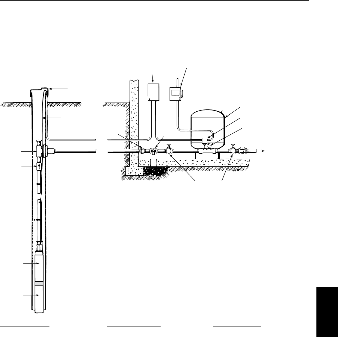
101
Appendix
SECTION 14: Appendix
Ventilated
Well Cap
Submersible
Cable
Pitless
Adapter
Check
Valve
Tape Cable
To Pipe
Add Torque Arrestor
(especially needed with
plastic pipe)
Pump
Motor
Control Box
(3-wire Models)
Electrical Disconnect
Pre-charged Tank
Pressure Switch
Pressure Gauge
To House Service
Relief
Valve
Union
Gate Valves
“Good” System
Features
• PressureSwitch
• Wire,(10-2w/ground)
• 1.5HP,20-22gpmpump
• 1.5HP,2-wiremotor
• 85gal.Tank
• OptionalMotorProtection(SPP-233P)
Benefits
• Cost
• Simpletouse
• PENTEKPSCmotorofferslower
operating cost
“Better” System
Features
• ControlBox
• PressureSwitch
• Wire,(10-3w/ground)
• 1.5HP,20-22gpmpump
• 1.5HP,3-wiremotor
• 85gal.Tank
• OptionalMotorProtection(SPP-233P)
Benefits
• Capacitorsandswitchescanbe
replaced without removing pump
• CSCRcontroloffershigherefficiency
• Higherstartingtorquethan2-wire
“Best” System
Features
• VFD
• PressureTransducer
• Wire,(12-3w/ground)
• 1.5HP,20-22gpmpump
• 1.5HP,3-Phasemotor
• 6gal.Tank
Benefits
• “City-like”pressure
• Loweroperatingcosts
• Softstart/stop
• MotorprotectionbuiltintoVFD
14.2 Choosing A Pump System
A typical well application can be set up using one of three
electrical configurations for single-phase power. The
samples below are based upon a system using a 1.5 HP,
20-22 gpm pump, with 400 feet of wire from electrical
disconnect to the motor. All configurations shown are
suitable methods for residential applications.
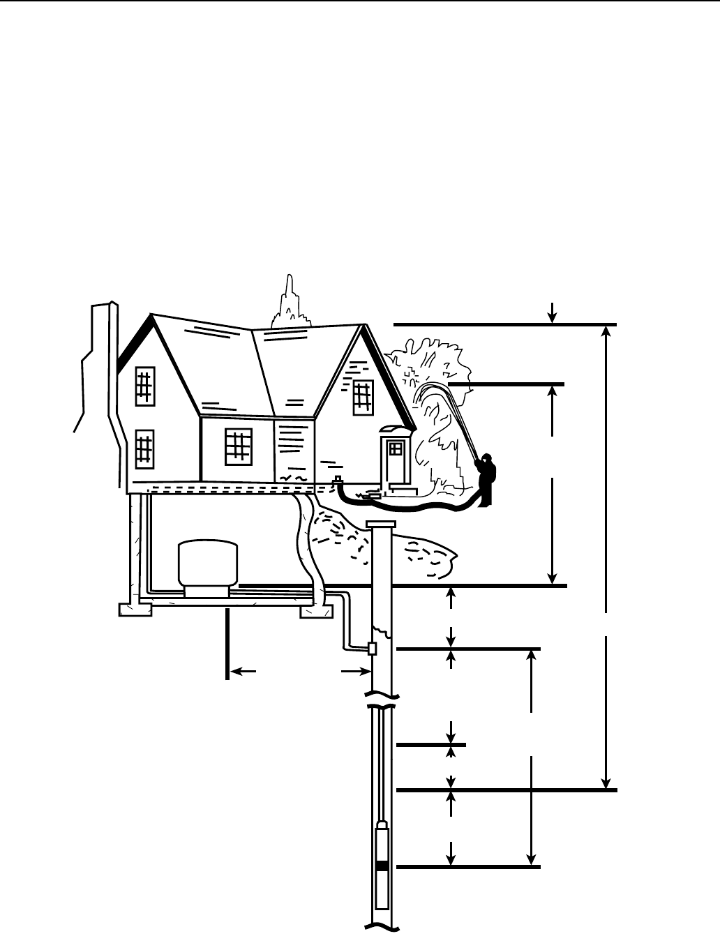
102
SECTION 14: Appendix
Horizontal
Pipe Run
Pump
Setting
Service
Pressure
Friction
Loss
Head
Standing
Water
Level
Submergence
Drawdown
Elevation
5183 0512
Figure 12-1: Common Pump Terminology
14.3 Sizing Submersible Pump, Motor,
and Tanks
Sizing a Submersible Pump
The following steps should be taken relative to properly
sizing the system.
1. Determine gpm of system and well.
2. Size of well casing and type.
3. Determine service pressure requirements.
4. Determine voltage and phase.
5. Determine discharge pipe size.
6. Calculate friction head loss.
7. Determine (total discharge) head.
8. Select the submersible pump for the above criteria,
and appropriate controls for the pump.
9. Select the proper size tank for minimum one minute
pump run time.
10. For starting frequency, refer to Section 5.10.
11. Determine the distance from the service entrance
panel to the pump motor.
12. Determine the size wire required based on the motors
maximum load amps and the distance from the
service entrance to the motor.
14.4 How to Select the Correct
Pumping Equipment

103
SECTION 14: Appendix
The answer to four basic questions will help select the
proper pump.
1. What is the size of the well? The inside diameter of
the well must be known so that the proper size pump
and drop pipe can be determined.
2. What is the submergence?
The vertical distance
in feet from the pump to the water level while the
pump is operating (see Figure 12-1). If the pump is
installed away from the well and is on higher ground,
this elevation must also be included. This must not be
confused with the standing waterlevel.
3. What should the average discharge pressure be?
Usual average discharge pressure is 50lbs. – half way
between the 40 lbs. to 60 lbs. switch setting of most
water systems. More pressure is needed when the
tank is installed away from the pump and at a higher
level, or when house or yard fixtures are above the
pump and tank, and a larger pump must be used.
4. What capacity is required? The discharge capacity
of the pump in gallons per minute that is needed
for satisfactory service. The pump should have
enough capacity so that it can deliver the total water
requirement in 2 hours of continuous operation. See
Table 12-1 for average water requirements.
Installation Terminology
Standing or Static Water Level – distance from top of
well to natural water level when pump is not operating.
Drawdown Distance – distance water level drops while
pump is operating.
Drawdown or Pumping Water Level – standing water
level plus drawdown.
Submergence – distance submersible pump intake
screen is installed below drawdown level.
Elevation – vertical distance between top of well and
service inlet.
Pump Setting – distance from top of well to pump
inletscreen.
Service Pressure – pressure required (in PSI) at
serviceinlet.
Friction Loss –loss of pressure due to friction of water
flowing through pipe and fittings.
Head – discharge head (in feet) delivered when pump is
operating at desired capacity.
Horizontal Pipe Run – horizontal distance between
service inlet and well.
“Top of Well” also means “Pitless Adapter Level” or
wellexit.
“Service Inlet” also means “Storage Tank Inlet”.
Selecting a Pump
TIP: PSI can be converted to equivalent feet of head by
multiplying by 2.31.
i.e. 60 psi = 138.6 feet of head
To choose a motor for your submersible pump you first
must know:
• FlowrequiredinGallonsperMinute
• Totalhead(Pumpinglevel,frictionlosses
and service pressure required)
Friction loss must be calculated, and depends upon total
length, diameter and type of pipe plus additions for each
fitting (valves, elbows...) in the line.
Refer to the product catalog for friction loss charts.
Table 12-1: Average Water Requirements
Av erage Water Requirements For
General Service Around The Home
And Farm
Each person per day, for all purposes .......50 gal.
Each horse, dry cow or beef animal.........12 gal.
Each milking cow . . . . . . . . . . . . . . . . . . . . . . . . 35 gal.
Each hog per day .........................4 gal.
Each sheep per day .......................2 gal.
Each 100 chickens per day .................4 gal.
Av erage Amount Of Water Required By
Various Home And Yard Fixtures
Drinking fountain, continuously
flowing ................ 50 to 100 gal. per day
Each shower bath...................Up to 60 gal.
To fill bathtub ...........................30 gal.
To flush toilet .........................2.5-6 gal.
To fill lavatory ............................2 gal.
To sprinkle 1/4” of water on each
1000 square feet of lawn ...............160 gal.
Dishwashing machine, per load .............3 gal.
Automatic washer, per load ..........Up to 50 gal.
Regeneration of domestic water softener 50-100 gal.
Av erage Flow Rate Requirements By
Various Fixtures
(gpm equals gal. per minute, gph equals gal. per hour)
Fixture New (at 60 PSI) Older Style
Shower 2.5 gpm 4 to 6 gpm
Bathtub 3 gpm 4 to 8 gpm
Toilet 1.6 gpm 4 to 5 gpm
Lavatory 2.5 gpm 1 to 3 gpm
Kitchen sink 2.2 gpm 2 to 3 gpm
1/2” hose and nozzle ....................200 gph
3/4” hose and nozzle ....................300 gph
Lawn sprinkler .........................120 gph
Appendix
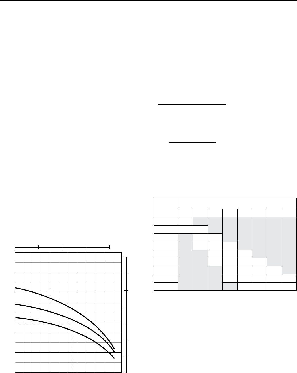
104
SECTION 14: Appendix
EXAMPLE
Assume we want 16 GPM at 60 PSI from a pump
drawdown level (pumping level) 100 feet below the
serviceinlet.
We have a 35 foot horizontal run of 1 1/4” plastic pipe
with two gate valves and four 90° elbows.
To find the Friction losses we must refer to friction loss
charts for pipe and fittings.
We find:
• 135feetofpipeforthetotalpiperun(100+35).
• 10equivalentfeetofpipeforthegatevalves(2x5)
• 28equivalentfeetofpipefortheelbows(7x4)
Add these for the total equivalent length of pipe = 173
• Inthefrictionlosscharts,findthelossofheadfor
173feet of 1 1/4” pipe at 16 gpm. (3.96 per 100’) =3.96
x 1.73 = 6.8 (round to 7.0)
Add: 7 Friction loss
100 Pumping level
139 60 PSI service pressure required (60
x2.31=138.6. Round to 139)
= 246 Total Dynamic Head.
From this sample curve we would choose the
11/2HPpump.
Locate a pump with a best efficiency point near the
desired flow rate (16 GPM) that meets the total head
requirements (246 TDH).
Selecting a pump in this manner gives you the most
efficient pump for your application.
14.5 Sizing Tanks
Tank should be sized to accomodate starting frequency in
Section 5.10.
Refer to the dealer catalog for tank selection. Otherwise,
the following procedure can be used.
Drawdown based on Boyle’s Law
Procedure:
1. Identify drawdown multiplier relating to
specific application.
2. Insert multiplier (X) into the following formula:
Pump GPM x Min Run Time = Minimum Tank
Multiplier (X) Capacity Required
Example: An example of a 20 GPM pump with a
minimum run time of 1 minute, installed on a
50-70 PSIG system pressure range:
20 GPM x 1 minute = 83.3 minimum U.S.
.24 (factor) gallon tank capacity
NOTICE: Drawdown will be affected by operating
temperature of the system, accuracy of the pressure
switch and gauge, the actual pre-charge pressure and the
rate offill.
Table 12-2: Drawdown Volume Multiplier
(Approximate)
Pump Off
Pressure
PSI
Pump Start Pressure –PSI
10 20 30 40 50 60 70 80
20 0.26
30 0.41 0.22
40 0.37 0.18
50 0.46 0.31 0.15
60 0.40 0.27 0.13
70 0.47 0.35 0.24 0.12
80 0.42 0.32 0.21 0.11
90 0.48 0.38 0.29 0.19 0.10
100 0.44 0.35 0.26 0.17
Ta nk sizing for Variable Frequency Drives
Variable Frequency Drives (VFD) may require slightly
different methods for figuring tank size. Refer to
Section 8 for VFD information.
Sample Pump Curve
TOTAL HEAD IN FEET
600
500
400
300
200
100
0 20 10 5 25 30 15
1 HP
1-1/2 HP
2 HP
CAPACITY GALLONS PER MINUTE
CAPACITY LITRES PER MINUTE
TOTAL HEAD IN METERS
25 0 50 75 100
175
150
125
100
75
50
25
0
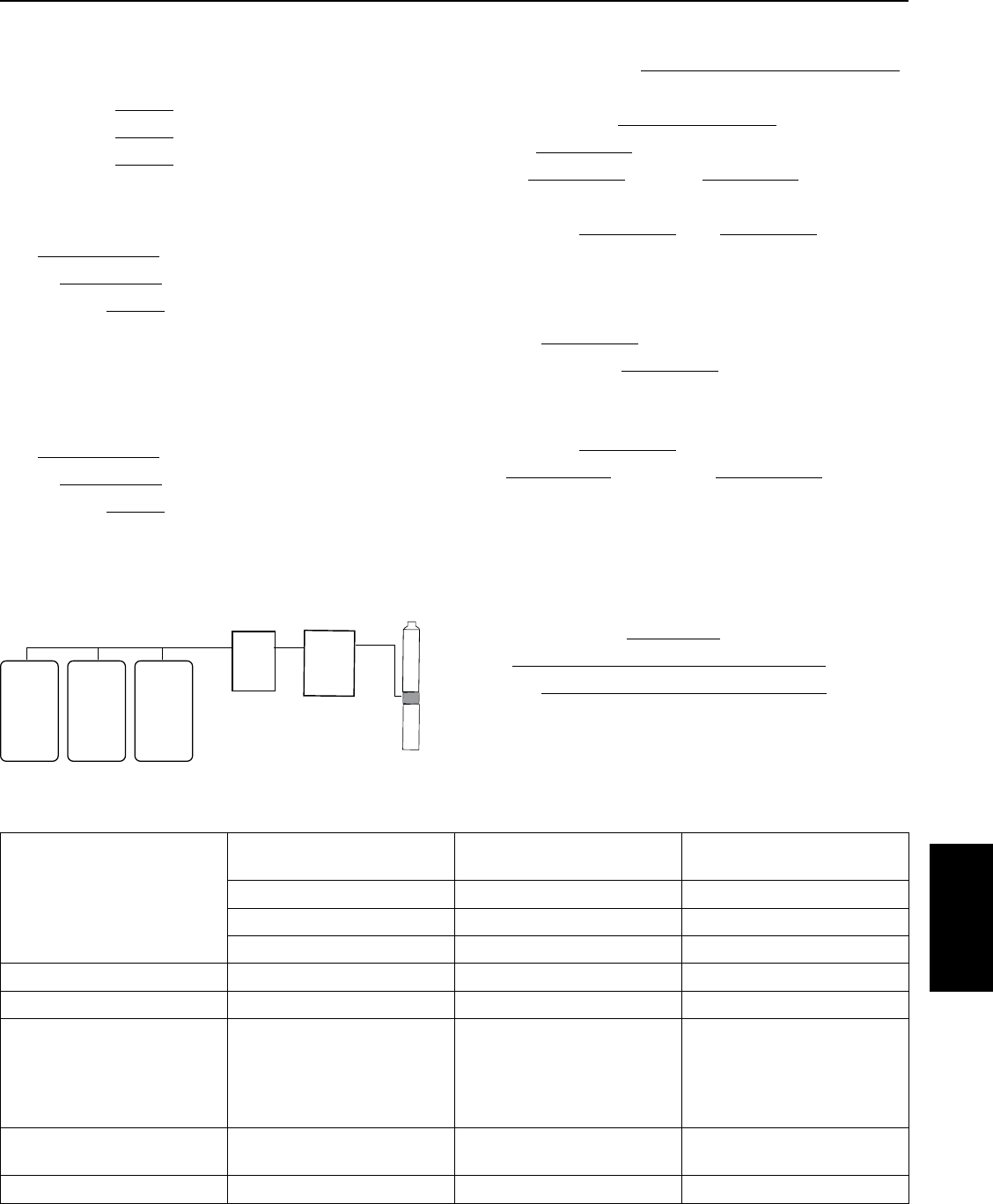
105
SECTION 14: Appendix
14.6 Record of Installation
Outside Power:
Transformer 1 KVA
Transformer 2 KVA
Transformer 3 KVA
Cables
From Service Entrance to Pump Control:
Size AWG/MCM
Length ft.
Temp. Rating °F / °C (circle one)
Check appropriate boxes
❏ Copper ❏ Aluminum
❏ Jacketed ❏ Individual Conductors
From Pump Control to Motor:
Size AWG/MCM
Length ft.
Temp. Rating °F / °C (circle one)
Check appropriate boxes
❏ Copper ❏ Aluminum
❏ Jacketed ❏ Individual Conductors
Pump Motor Control Panel
Manufacturer / Model
Circuit Protection:
❏ Circuit Breaker: Amps
❏ Fuse Amps
❏ Std. ❏ Delay
Starter
Manufacturer Size
Type
❏ Autotransformer
❏ Full Voltage
❏ Other
Time to full voltage sec.
Heaters
Manufacturer
Qty: Amp setting
Installation Data
Controls grounded to:
❏ Motor ❏ Well Head
❏ Power Supply ❏ Buried Rod
Grounding wire size AWG / MCM
Date
Location
Motor serial number:
T1 T2 T3
Service
Entrance
Transformers
Pump
Control
Pump
Assemb
ly
Motor Current - Balance Worksheet
Arrangement 1
Amps
Arrangement 2
Amps
Arrangement 3
Amps
L1–T1 = L1–T3 = L1–T2 =
L2–T2 = L2–T1 = L2–T3 =
L3–T3 = L3–T2 = L3–T1 =
Total Amps
Average Amps
From Average Amps
Deviation L1
Deviation L2
Deviation L3
————
————
————
————
————
————
————
————
————
% Current Unbalance
Largest Deviation
% Unbalance + % % %
Appendix
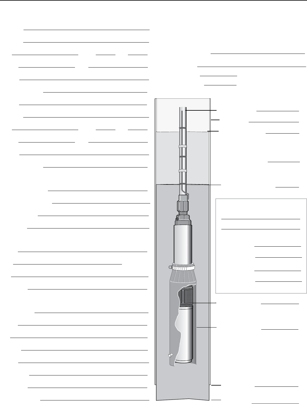
106
SECTION 14: Appendix
Record of Installation
Installer
Address
City State Zip
Phone Fax
E-mail
Who to contact?
Owner
Address
City State Zip
Phone Fax
E-mail
Who to contact?
Installation
Well Identification
Water Temperature
Date Installed
Signature
Pump Information
Model
GPM @ft. TDH
PSI
Date code
Motor Nameplate Information
Manufacture
Model
HP
Voltage
Phase
Max Amps
Date code
Serial Number
VFD (Variable Frequency Drive)
Information
Drive Manufacturer
Model Number
❏ Input Filters
❏ Output Filters
Down Pipe Dia.
Flow Sleeve Dia.
Perforated Casing
From
To
Pump Inlet depth
Casing Dia.
Static Water Level.
Total Dynamic Head
Drawdown Water Level.
Check Valve Locations
Well Depth
Casing Depth
Well Screen
From
To

NOTES

NOTES

293 WRIGHT STREET, DELAVAN, WI 53115 WWW.PUMPS.COM
PH: 262-728-5551 ORDERS FAX: 262-728-7323
Because we are continuously improving our products and services, Pentair reserves the right to change specifications without prior notice.
© 2013 Pentair Ltd. All Rights Reserved. PN793 (08/20/13)
