145393 3 Hydromatic Sp40 Curves 6780 BV 1_B A1 User Manual
554782 3 Hydromatic Sp40 Curves 554782_3_Hydromatic SP40 Curves 554782_3_Hydromatic SP40 Curves pdf pumpproducts
User Manual: Pump 145393 3 Hydromatic Sp40 Curves
Open the PDF directly: View PDF ![]() .
.
Page Count: 6
Conditions of Service:
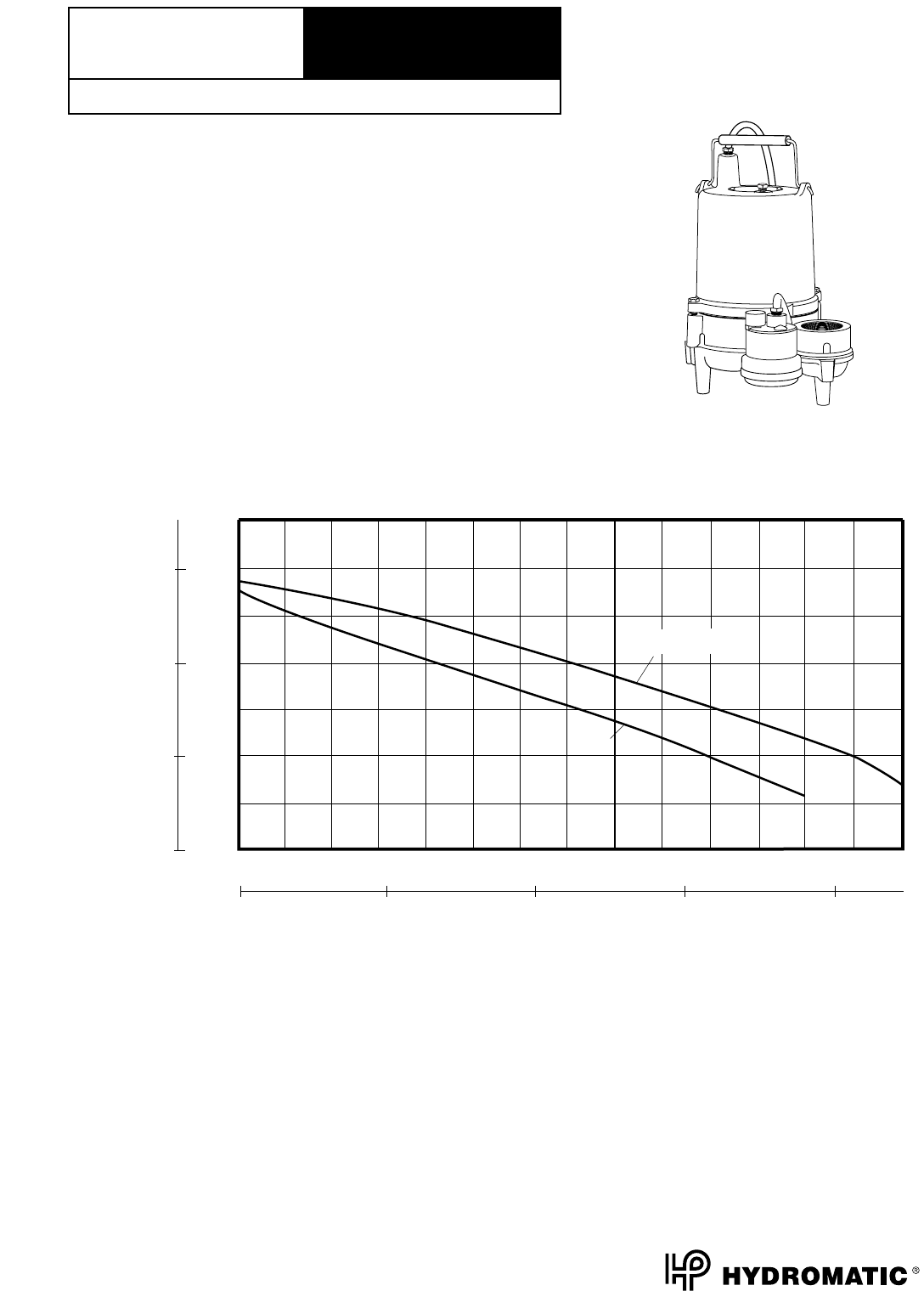
GPM:______ TDH:______
0
10
20
30
SP50 & SP50AB
SP40
200406080100 120 140
TOTAL HEAD IN FEET
Capacity-U.S. G.P.M.
Liters/Second 02864
HEAD-METERS
0
3
6
9
The curves reflect maximum performance characteristics without exceeding full load (Nameplate) horsepower. All pumps have
a service factor of 1.2. Operation is recommended in the bounded area with operational point within the curve limit. Performance
curves are based on actual tests with clear water at 70° F. and 1280 feet site elevation.
SP40
RPM:
1750
Discharge:
2"
Solids:
1-1/4"
Performance
Data
Wholesale Products
Page:
6140-1
Section:
Performance Data
Dated:
January 2001
Wholesale Products
Page:
6140-2
Section:
Dimensional Data
Dated:
January 2001
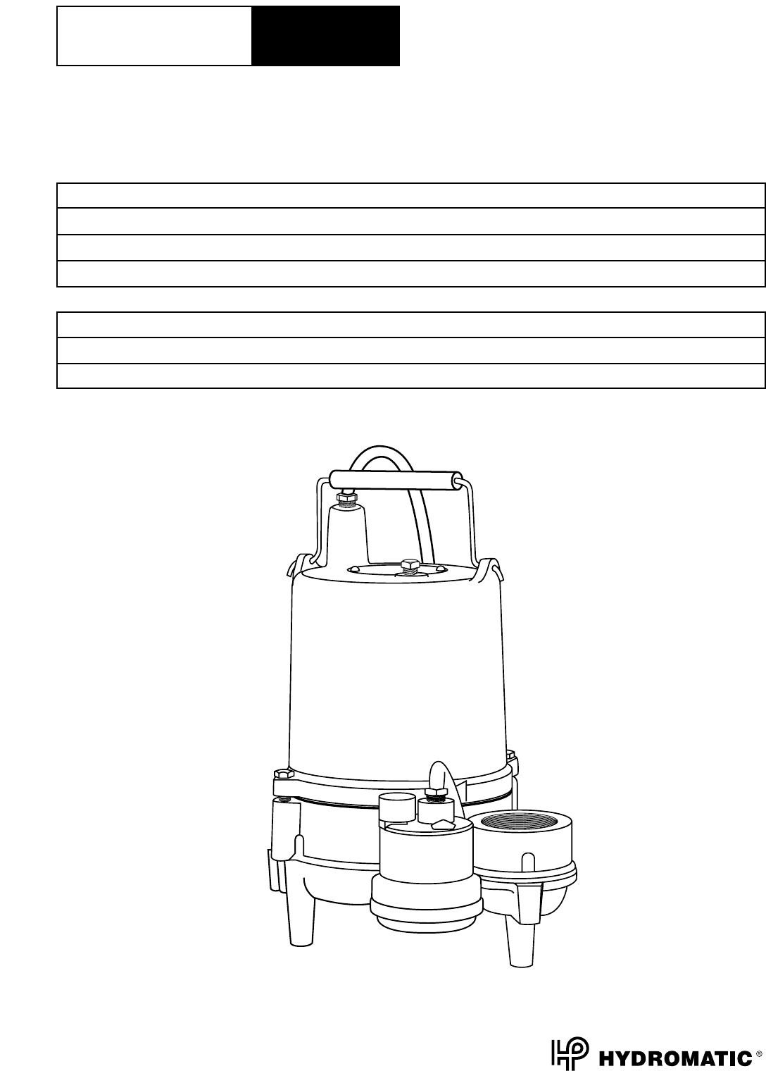
SP40
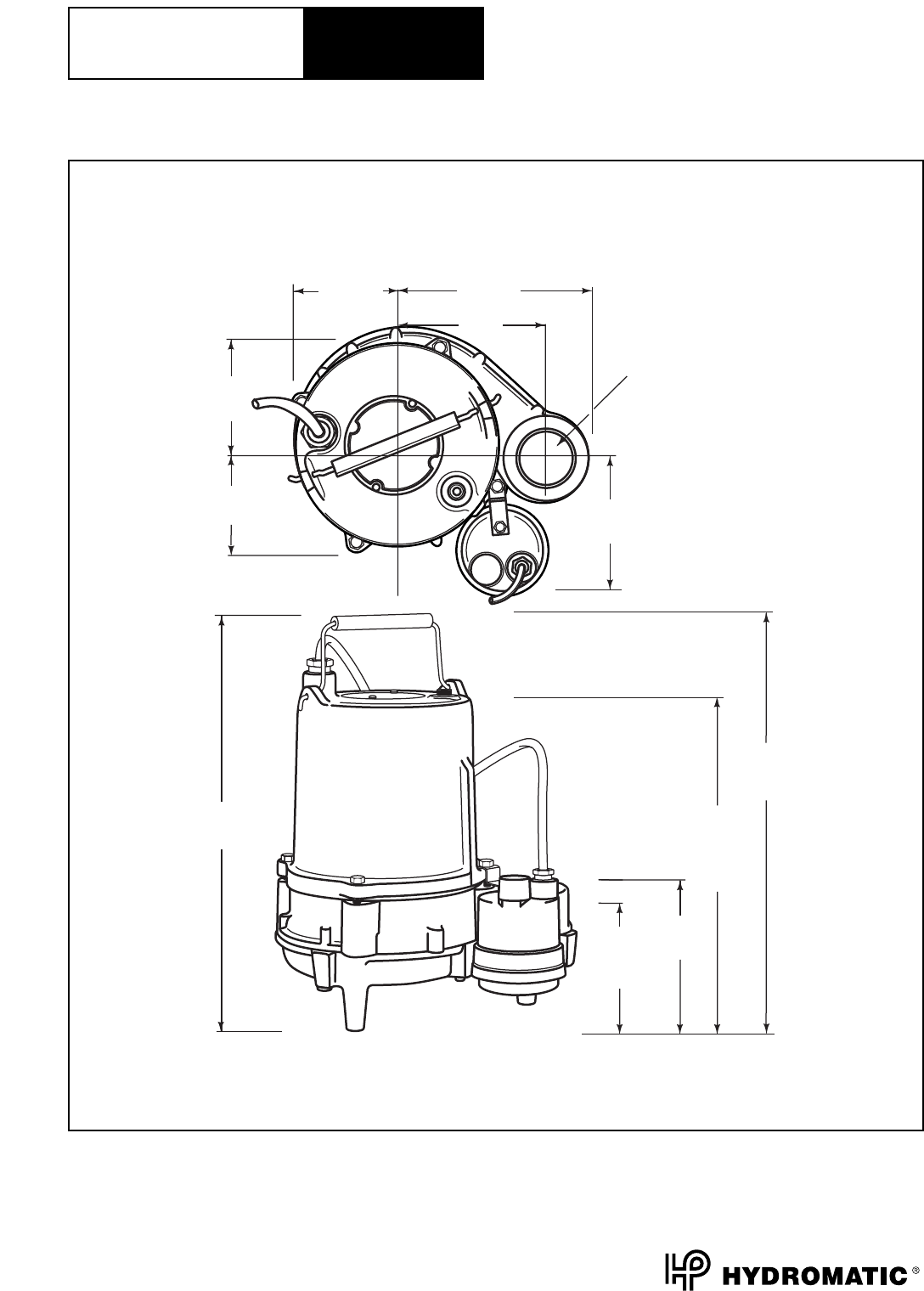
Dimensional
Data
3-3/4
(95)
PUMP OFF
4-5/16
(109)
13-1/16
(331) 12-1/4
(311)
PUMP
ON
14-1/16
(357)
3-3/4
(95)
4-5/16
(109)
3-15/16
(100)
6-13/16
(173)
5-1/8
(130)
2 (50) NPT
DISCHARGE
4-15/16
(125)
DISCHARGE
HEIGHT
All dimensions in inches. Metric for international use. Component dimensions may vary ± 1/8 inch. Dimensional data not
for construction purpose unless certified. Dimensions and weights are approximate. On/Off level adjustable.
We reserve the right to make revisions to our product (s) and the product (s) specifications without notice.
Wholesale Products
Page:
6140-3
Section:
Electrical Data
Dated:
January 2001
SP40
Electrical
Data
MODEL: SP40, Sewage Ejector
HP VOLTAGE PHASE NEC CODE SERVICE FACTOR FULL LOAD AMPS
4/10 115 1 - 1 9.5
4/10 230 1 - 1 4.7
R.P.M. 1750
MOTOR TYPE OIL FILLED WITH AUTOMATIC RESET THERMAL OVERLOAD
GENERAL INSULATION CLASS A
MOTOR PROTECTION AUTOMATIC RESET / THERMAL OVERLOAD

Wholesale Products
Page:
6140-4
Section:
Technical Data
Dated:
January 2001
SP40
Technical
Data
MATERIALS OF
CONSTRUCTION
MODEL: SP40, Sewage Ejector
Physical Data:
DISCHARGE SIZE 2" NPT
SOLIDS SIZE 1 1/4"
IMPELLER TYPE NON CLOG
CABLE LENGTH 10' STANDARD
20' OPTIONAL
PA INT PAINTED AFTER ASSEMBLY, DARK GREEN, WATER REDUCIBLE
ENAMEL, ONE COAT, AIR DRIED.
Temperature:
MAXIMUM LIQUID 140°F
MAXIMUM STATOR
OIL FLASH POINT
Technical Data:
POWER CORD TYPE SJTW
MOTOR HOUSING CAST IRON
CASING CAST IRON
IMPELLER THERMOPLASTIC
MOTOR SHAFT STEEL
HARDWARE STAINLESS STEEL
“O” RINGS BUNA - N
MECHANICAL SEALS
Standard: CARBON / CERAMIC
UPPER BEARING SINGLE ROW-BALL
LOWER BEARING SINGLE ROW-BALL

Wholesale Products
Page:
6140-5
Section:
Specification Data
Dated:
January 2001
SUBMERSIBLE SEWAGE EJECTOR MODEL:
SP40
1.01 GENERAL
Contractor shall furnish all labor, materials, equipment and incidentals required to provide (Qty.)
submersible centrifugal sewage ejector pump(s) as specified herein. The pump model covered
in this specification is the SP40. The pump furnished for this application shall be
MODEL _________ as manufactured by Hydromatic Pumps.
2.01 DESIGN CONDITIONS
Each pump shall be rated _____ H.P., _____ volts, _____ phase, _____ hertz and operate at ______
RPM.
3.01 OPERATING CONDITIONS
The pump shall deliver _____ U.S. GPM/LPS at _____ feet/meters TDH, and handle a _____ inch solid.
The curve submitted for approval shall state, in addition to head and capacity performance, solid
handling capability, amp rating, and design impeller diameter.
4.01 CONSTRUCTION
Each pump shall be of the sealed submersible type, incorporating features normally found in pumps
furnished for the residential market.
These features include:
1. The pump volute, motor, and seal housing shall be high quality gray cast iron, ASTM A-48, Class 30.
2. The pump inlet shall be open and clear, without screening to provide access for sewage and solids.
3. All external mating parts shall be machined and Buna N, O-Ring sealed.
4. All fasteners exposed to the pumped liquid shall be 300 series stainless steel.
5. All power cords shall be water resistant UL or CSA approved, with double insulation, and sized as
a function of Amp. draw.
5.01 MOTOR AND SHAFT
The stator, rotor and bearings shall be mounted in a sealed submersible type housing. Single phase
motors shall be split phase or capacitor start with centrifugal switch. Three phase motors shall be
Polyphase. Full Load and Locked Rotor Amps as well as Start and Run winding resistance shall be
tabulated for each pump.
SP40
Specification
Data
Wholesale Products
Page:
6140-6
Section:
Specification Data
Dated:
January 2001
6.01 BEARINGS, SHAFT AND MECHANICAL SEAL
An upper radial and lower thrust bearing shall be required. These shall be heavy duty single row ball
bearings which are permanently and continuously lubricated and cooled by the dielectric oil which fills the
motor housing. The motor shaft shall be stainless steel and sealed from the pumped liquid with a carbon
ceramic mechanical seal.
7.01 IMPELLER
The Impeller shall be high capacity, two vane, non-clog design with pump out vanes on the back side.
These vanes wash out grit and stringy material that will damage the shaft and mechanical seal.
8.01 AUTOMATIC CONTROL
All single phase pumps should be capable of automatic operation.
9.01 PRESSURE SWITCH
The Single Phase SP40 pump is furnished with a pressure diaphragm switch that features a piggy-back
plug that allows the pump to be operated manually without removal from the sump.
10.01 PAINTING
All cast iron parts shall be painted before assembly with a water reducible alkyd air dried enamel.
The paint shall be applied in one coat with a minimum thickness of 3 to 4 mils.
11.01 TESTING
All pumps shall be individually tested to include the following:
1. The pump and power cord shall be visually inspected for imperfections, cuts or nicks.
2. The pump shall have a ground continuity check and the motor chamber shall be Hi-potted to
test for moisture content and/or insulation defects.
3. The motor and volute housing shall be pressurized and a 10 second air leak decay test run.
4. Oil is added, and the pump is run. Voltage and current are monitored visually, electronically,
and the tester listens for any noise or malfunction.
SP40
Specification
Data
