15667 1 Armstrong Hydronic Catalog User Manual
548387 1 Armstrong Hydronic Catalog 548387_1_Armstrong Hydronic Catalog
548383 1 Armstrong Hydronic Catalog 548383_1_Armstrong Hydronic Catalog
548380 1 Armstrong Hydronic Catalog 548380_1_Armstrong Hydronic Catalog
548385 1 Armstrong Hydronic Catalog 548385_1_Armstrong Hydronic Catalog
548384 1 Armstrong Hydronic Catalog 548384_1_Armstrong Hydronic Catalog
User Manual: Pump 15667 1 Armstrong Hydronic Catalog
Open the PDF directly: View PDF ![]() .
.
Page Count: 218 [warning: Documents this large are best viewed by clicking the View PDF Link!]
- commercial & residential pumps
- Design Envelope Compass Circulators
- Astro 2 Circulators
- Astro 2 Hot Water Recirculation Systems
- Astro 2 24-hour timer
- Aquastat controls
- Astro Express 2 Hot Water Recirculation
- S&H 3-Piece Circulators
- 1050 & 1060 3-Piece Circulators
- E.2 Circulators
- E.2 Circulator Spool Pieces
- 4270 & 4270 Stock Motor Mounted Pumps
- 4360 Pump-in-a-Box
- 4380 Pump-in-a-Box
- Design Envelope 4300/4380 Pump-in-a-Box
- hydronic specialties
- circuit balancing valves (cbv)
- replacement parts
- parts look up
- competition circulator cross reference
- technical data
- Pump Formulas
- Pressures & Altitudes
- Freezing & Boiling Points
- Ethylene Glycol Properties
- Propylene Glycol Properties
- Water Properties
- Useful System Curve Formulas
- Pipe Maximum Pressures
- Hydraulic Resistance
- Pipe Information
- Pipe Fittings & Valves Friction Loss
- Water Flow Calculator
- Unit Conversions
- Typical Symbols
- Product Solution Outlines/Brochures

file no: 10.01
date: november 2014
supersedes: 10.01
date: august 2014
catalog
Hydronic solutions
compass
e.2 circulators
cbv
parts section
commercial & residential pumps 3
Design Envelope Compass Circulators 3
Astro 2 Circulators 5
Astro 2 Hot Water Recirculation Systems 11
Astro 2 24-hour timer 15
Aquastat controls 17
Astro Express 2 Hot Water Recirculation 19
S&H 3-Piece Circulators 21
1050 & 1060 3-Piece Circulators 29
E.2 Circulators 33
E.2 Circulator Spool Pieces 37
4270 Motor Mounted Pumps 39
4360 Pump-in-a-Box
(4360, 4380, DE 4300 & DE 4380) 41
hydronic specialties 53
Air Vents (Automatic & Float) 53
Air Removal Trap 57
Diaphragm Expansion Tanks 59
Relief and Reducing Valves 61
circuit balancing valves (cbv) 63
Circuit Balancing Valves - Mini Sweat 63
Circuit Balancing Valves - Venturi 65
Circuit Balancing Valves - ANSI Flanged 69
Circuit Balancing Valves - ANSI Grooved 73
Flange Adapter Kits 77
PT Port & Extensions 79
Meters 81
Orifice Indicators 85
CBV Balancing Wheel 87
replacement parts 89
S&H Circulator Less Volute 89
Companion Flanges 91
Hardware Kits 95
Flange Hardware Kits - Cross Reference 97
Flex Flange 99
Flange Kits 101
Seal Bearing Assemblies 105
Coupler Assemblies 109
Motors 111
Seal Kits 113
Impellers 114
Gaskets 118
Pump Bodies 119
parts look up 121
s-25 121
s-35 122
h-32 123
s-35 124
s-45 125
s-46 127
h-41 128
s-55 129
s-57 130
h-51 131
h-52 132
h-53 133
h-54 134
s-69 135
4030 Base Mounted Pumps - Parts
Cross Reference 149
4280 Motor Mounted Pumps - Parts
Cross Reference 161
Shell & Tube Heat Exchangers - Parts
Cross Reference 171
4380 & 4360 VIL Pumps - Parts
Cross Reference 173
competition circulator
cross reference 175
Design Envelope COMPASS
Circulators Cross Reference 175
S&H Circulators Cross Reference 176
E.2 Circulators Cross Reference 177
Astro 2 Circulators Cross Reference 179
technical data 181
contents

3
|
HYDRONIC SOLUTIONS CATALOG
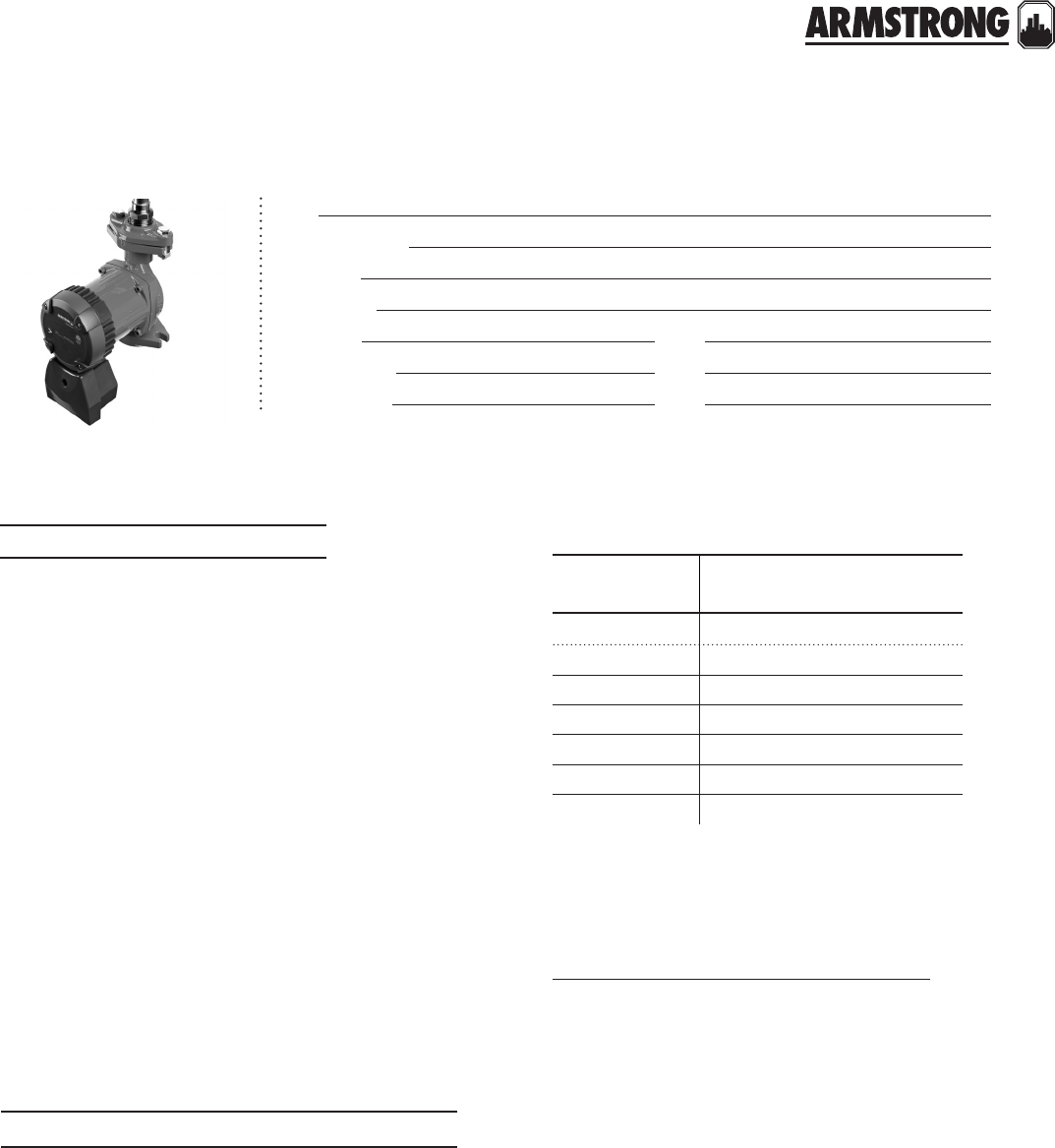
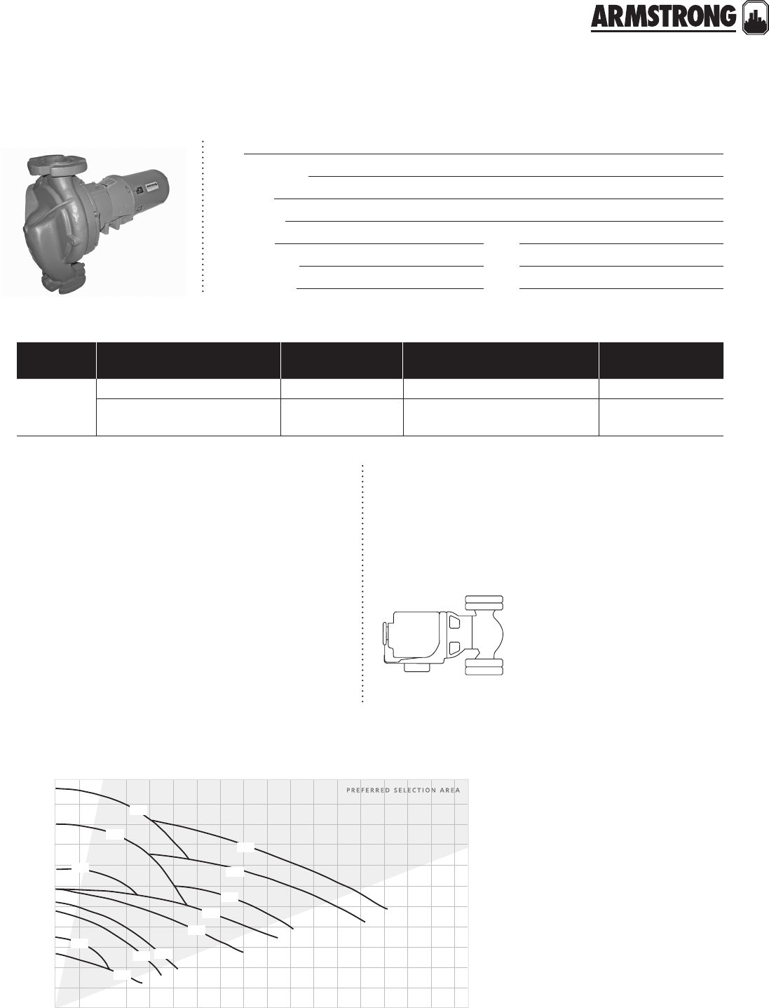
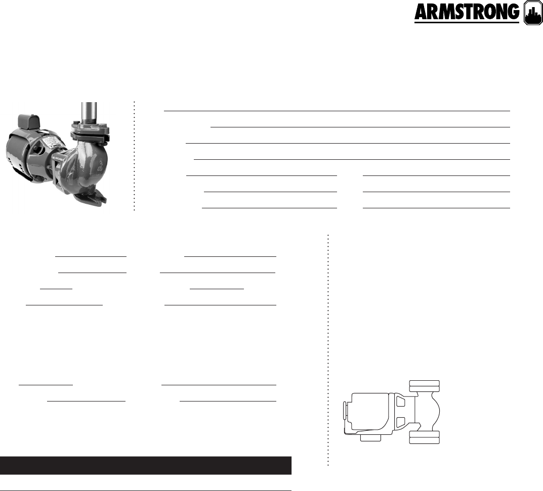
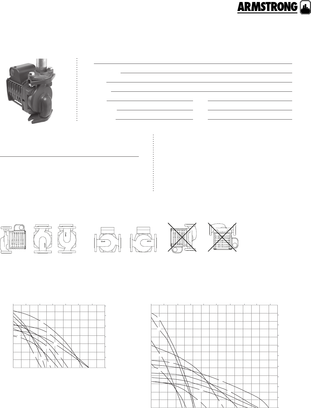
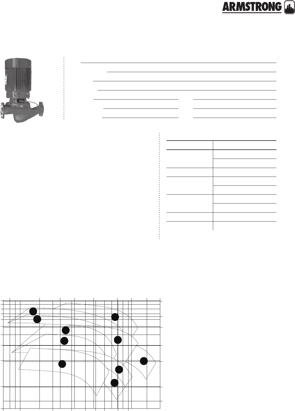
DESIGN ENVELOPE COMPASS CIRCULATORS
VARIABLE SPEED WET ROTOR
|
SUBMITTAL
Job:
Representative:
Engineer:
Contractor:
Order no: Date:
Submitted by: Date:
Approved by: Date:
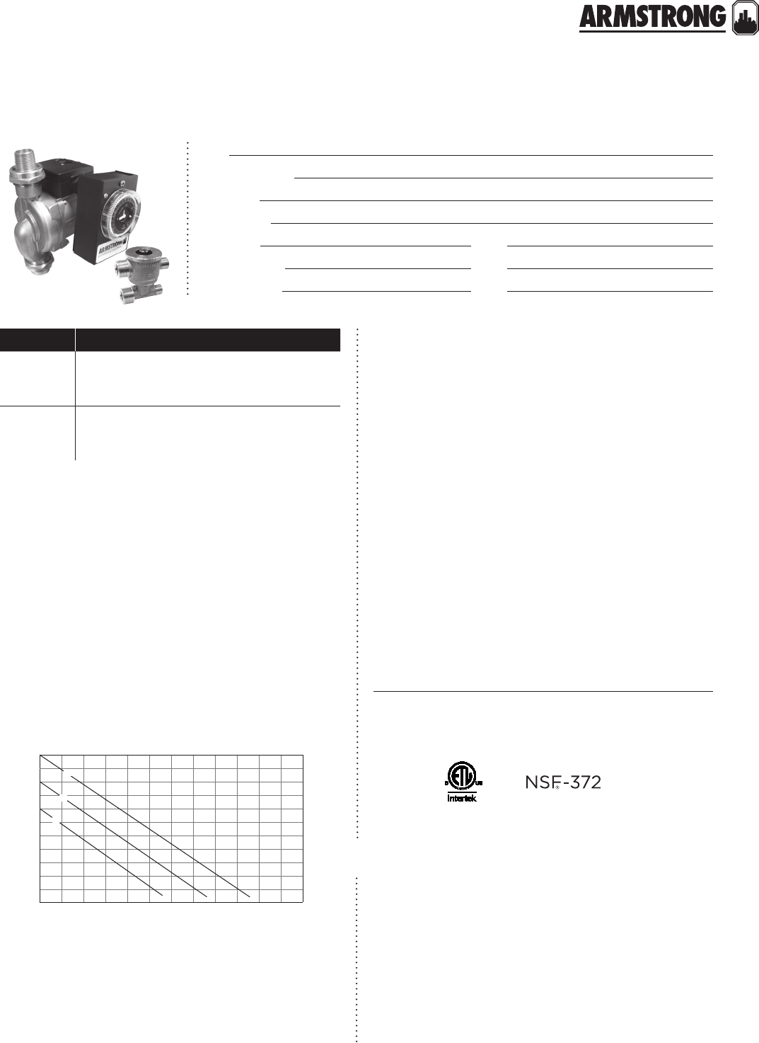
technical data
Supply voltage: 1 × 115 v – 10%/+ 6%, 60 Hz
Motor protection: The pump requires no external
motor protection.
Maximum working temperature: 230°f (110°c) maximum
Maximum working pressure: 150 psi (10 bar).
Maximum relative air humidity (rh): 95%.
Flow range: 0 – 20 USgpm (0 to 1.26 L/s)
Head range: 0 – 20.0 feet (0 to 6.09 m)
Enclosure class: Type 2
Insulation class: h
Certification: etl listed for US and Canada (conforms to
ulstd.778 certified to csa std. c22.2 no.108-01)
*nsf 372 (for stainless steel models)
inlet pressure
Minimum inlet pressure in relation to liquid temperature:
Sound pressure level: The sound pressure level of the pump is
lower than 43 dB(A).
Ambient temperature: 32°f (0°c) – 104°f (40°c)
Pumped liquids: Water or water Glycol mix.
Liquid temperature: 36°f (2°c) – 230°f (110°c)**
minimum maximum
Amp 0.05 0.65
Watt 545
liquid temperature minimum inlet pressure
150°f (65°c) 3.0 ft (0.91 m)
167°f (75°c) 4.4 ft (1.34 m)
194°f (90°c) 9.2 ft (2.8 m)
230°f (110°c) 36.1 ft (11.0 m)
materials of construction
Pump body: Cast iron (closed systems)
Stainless steel* (open systems)
Impeller: Noryl
Shaft: Ceramic
Bearings: Ceramic
Gasket material: epdm
hardware kit
Companion flange kit (contains two (2) flanges,
hardware and gaskets)
Cast iron: 0.75", 1", 1.25", 1.5"
Bronze: 0 .75", 1", 1 . 2 5", 1 . 5"
To avoid condensation in the control box and stator, the
liquid temperature must always be higher than the
ambient temperature.
ambient
temperature liquid temperature
min. max.
32°f (0°c) 35.6°f (2°c) 230°f (110°c)
50°f (10°c) 10°c (50°f) 230°f (110°c)
68°f (20°c) 68°f (20°c) 230°f (110°c)
86°f (30°c) 86°f (30°c) 230°f (110°c)
95°f (35°c) 95°f (35°c) 194°f (90°c)
104°f (40°c) 104°f (40°c) 158°f (70°c)
back to
contents
<
4
|
HYDRONIC SOLUTIONS CATALOG
DESIGN ENVELOPE COMPASS CIRCULATORS
VARIABLE SPEED WET ROTOR
|
SUBMITTAL
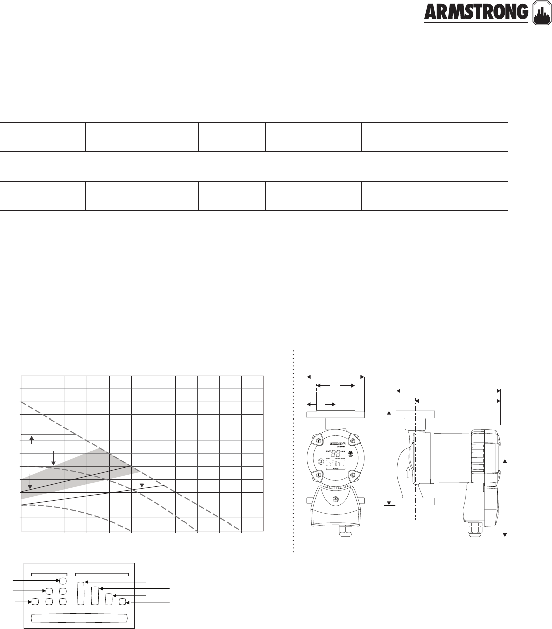
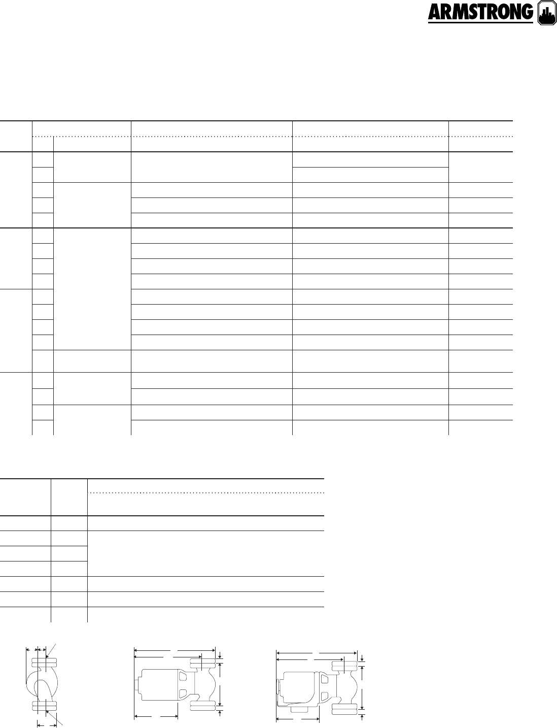
compass performance curves
pc4pc3
pc2pc1
i
ii
iii
speed pressure curve
auto
compass performance curves
pc1
pc2
pc3
pc4
iii
ii
head - ft.wg.
flow - usgpm
i
20
22
24
20 22
18
18
16
16
14
14
12
12
10
10
8
8
4
4
6
6
2
2
0
0
auto
Lights on the display indicate the Control mode selected.
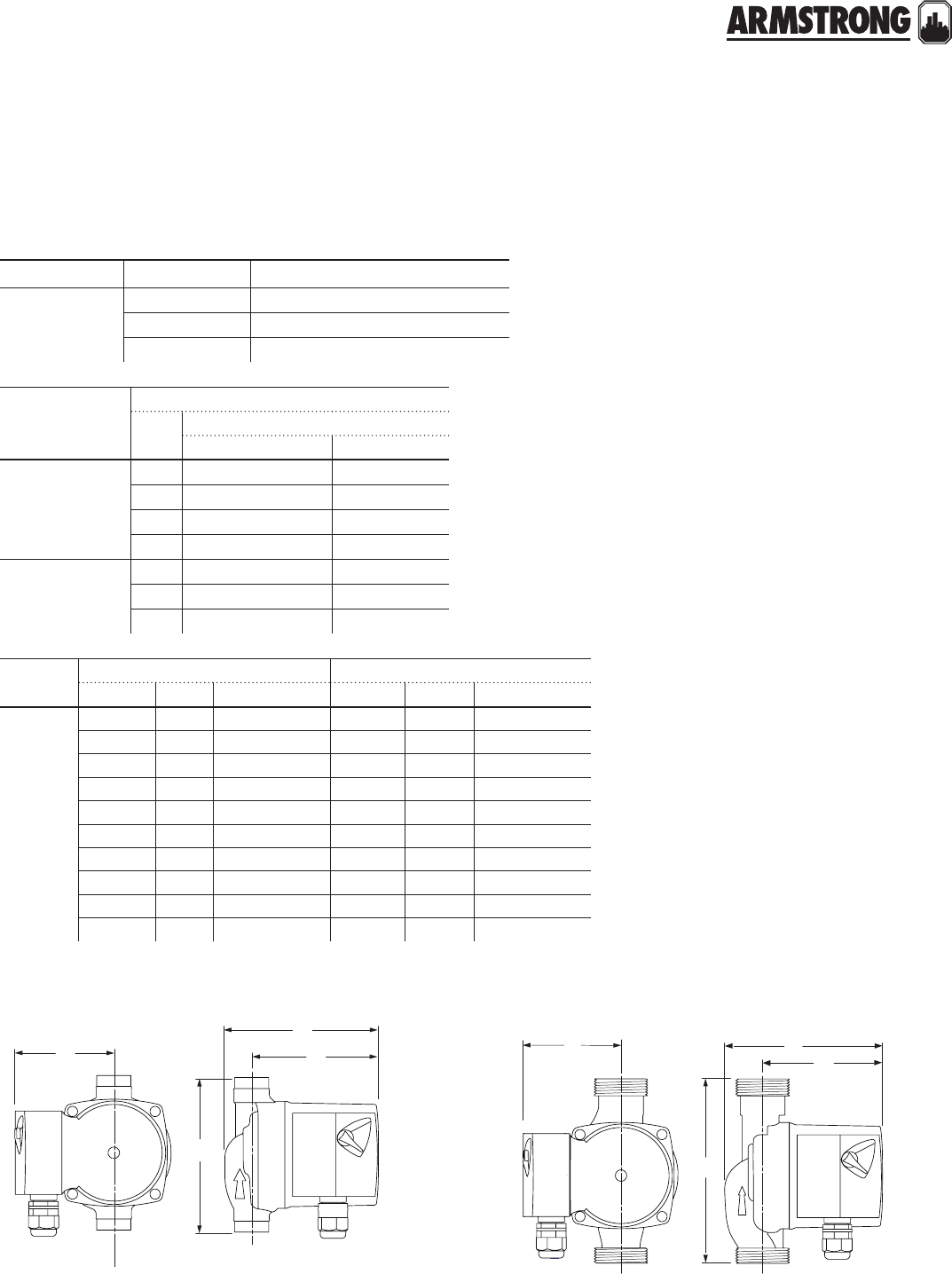
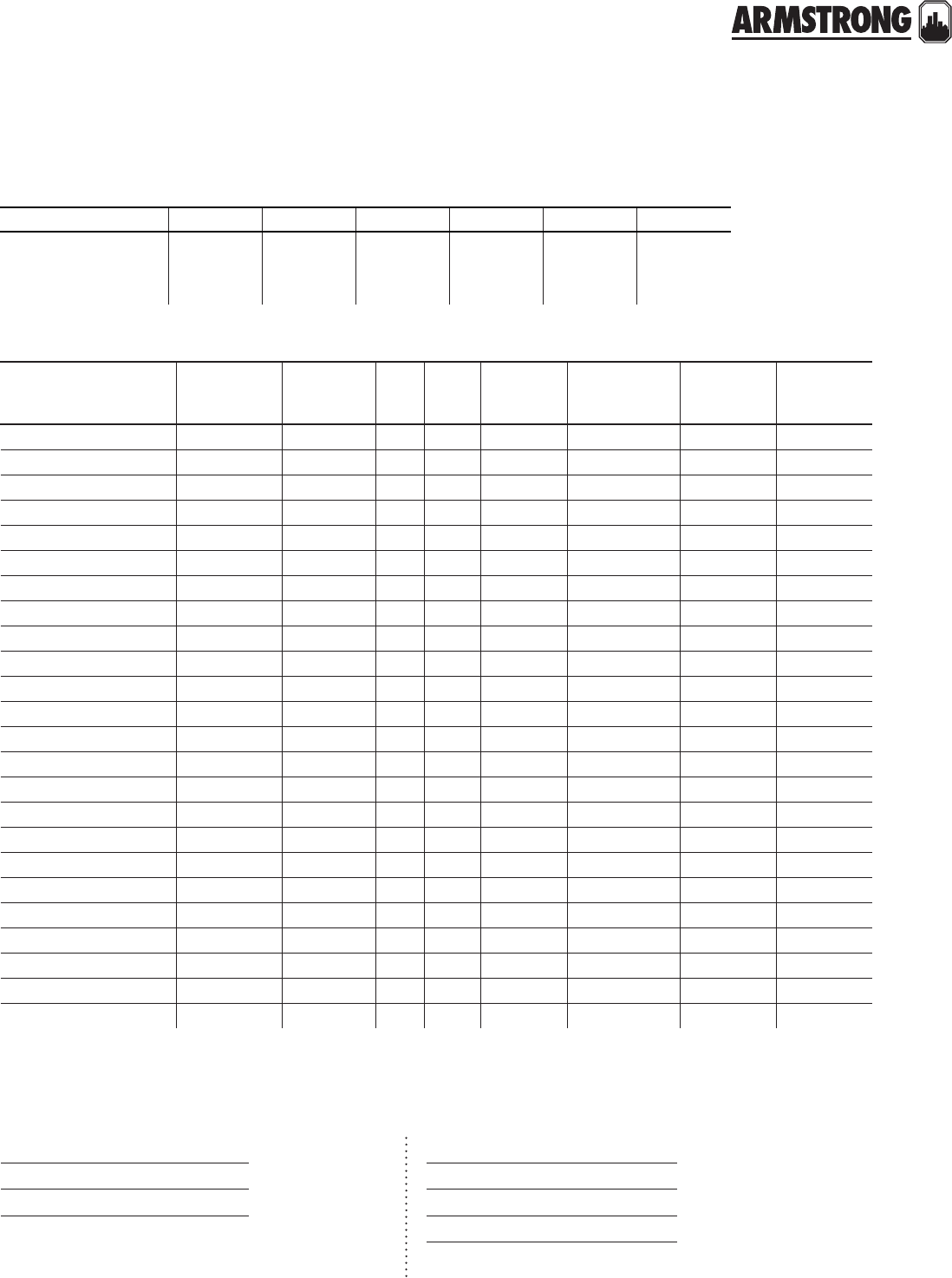
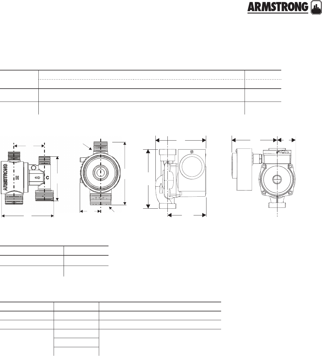
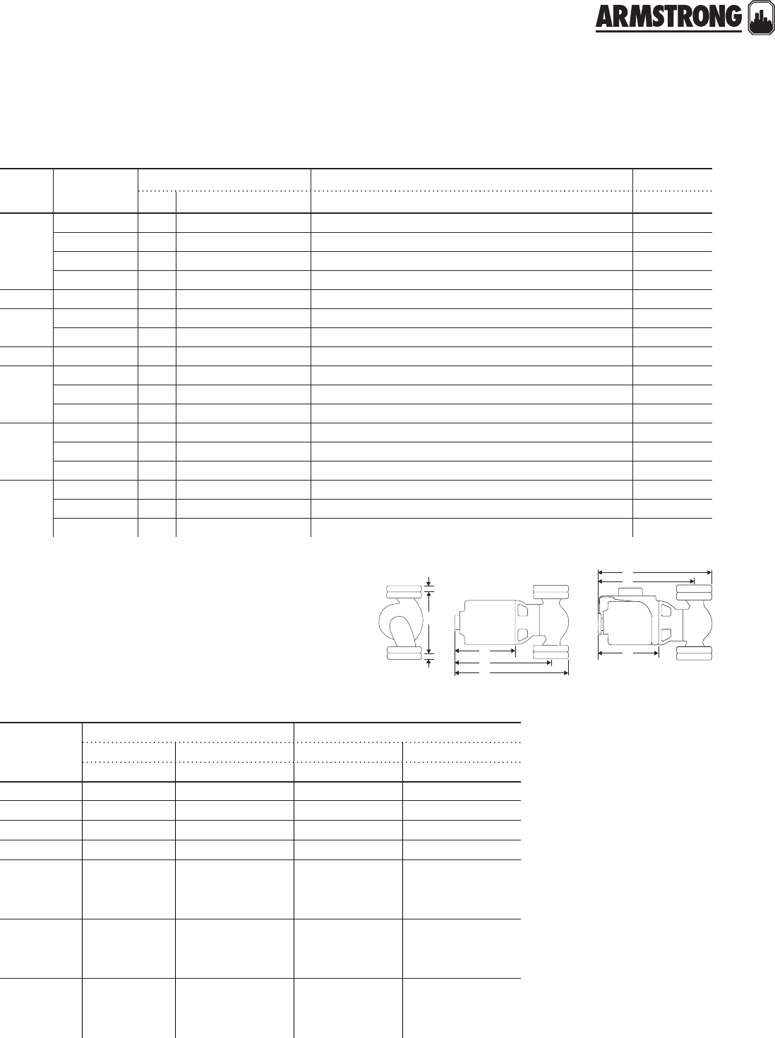
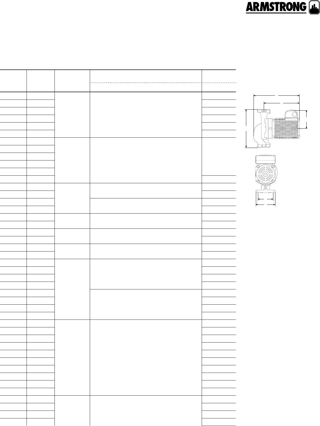
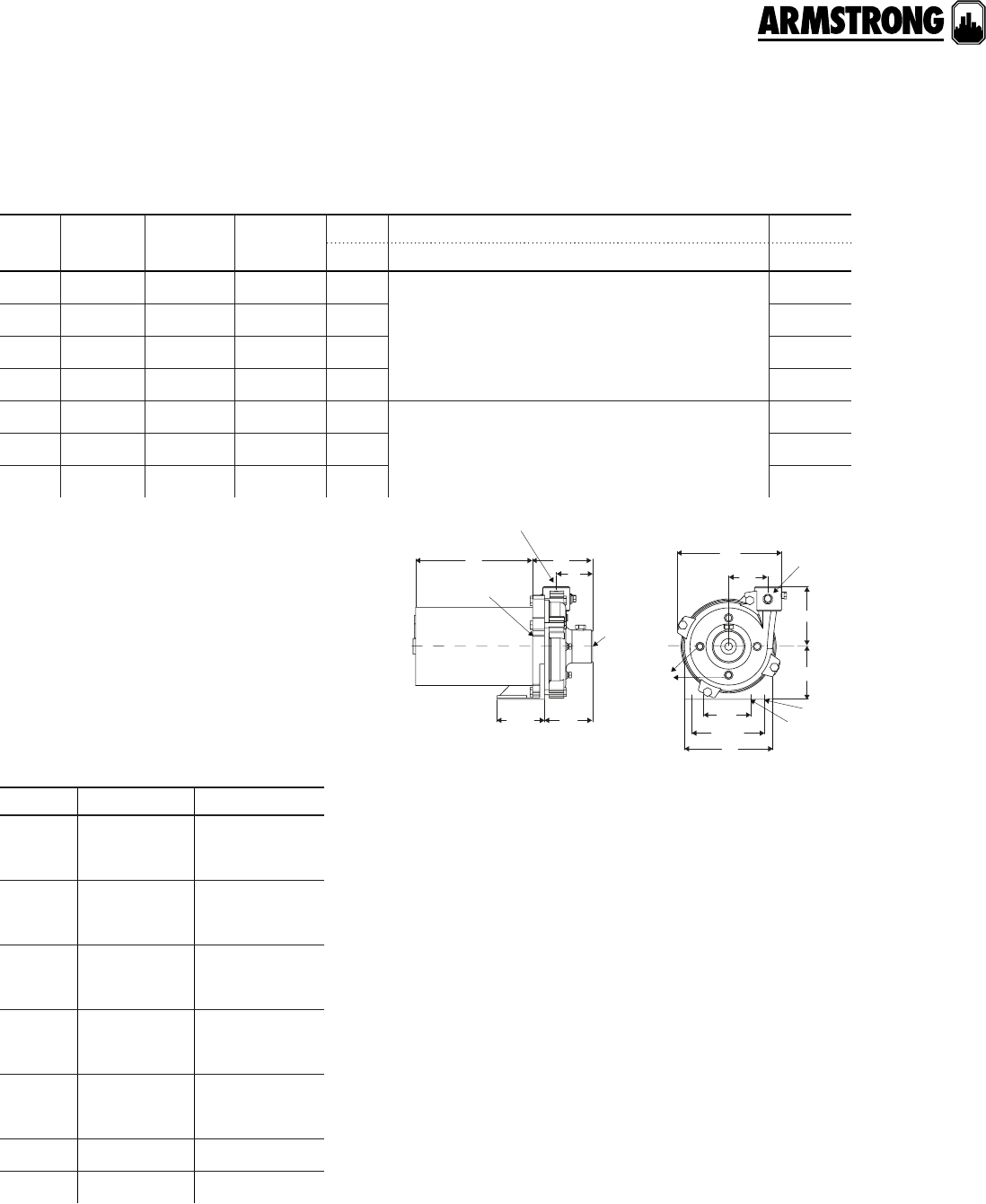
dimensions and weights
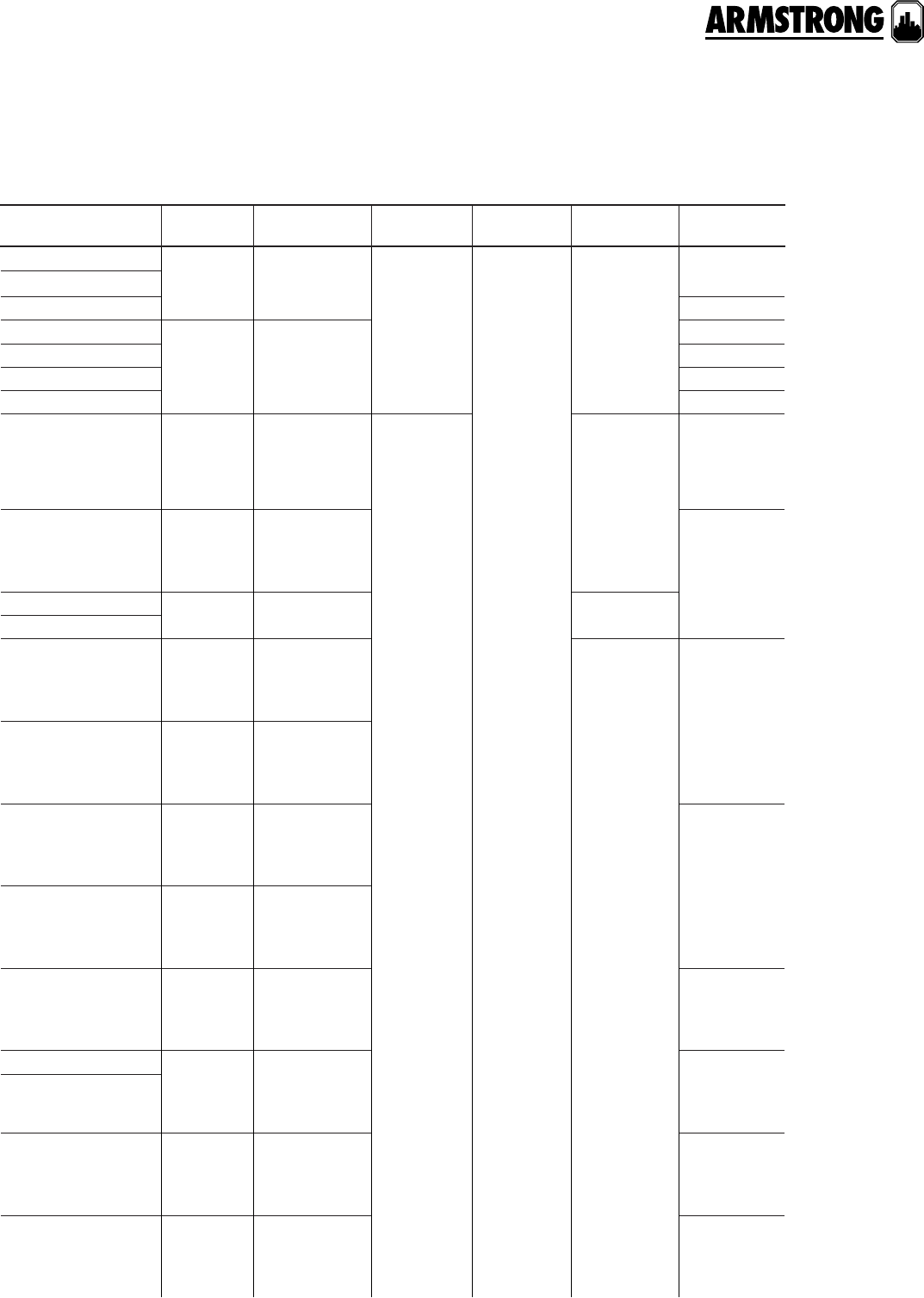
stainless steel* part number a b c d e f g connection
type& size weight
Compass 20-20 ss
flange 180203-607 6.50
(165)
7.08
(180)
5.75
(146)
4.00
(102)
2.00
(50)
3.25
(80)
5.31
(135)
Flange – (2) ½"
dia. bolt holes 8.0 (3.6)
cast iron part number a b c d e f g connection
type & size weight
Compass 20-20 ci
flange 180203-606 6.50
(165)
7.08
(180)
5.75
(146)
4.00
(102)
2.00
(50)
3.25
(80)
5.31
(135)
Flange – (2) ½"
dia. bolt holes 8.0 (3.6)
note:
All dimensions are in inches (mm) and weights in lbs (kg).
*Certified <0.25 weighted average percent lead and complies with California Health and
Safety Code Section 116875 (commonly known as ab 1953).
** For open systems, it is recommended that the liquid temperature be less than 150°f
(65°c) to avoid precipitation of calcium.
e
f
d
b
c
a
g
(on center)
compass flange
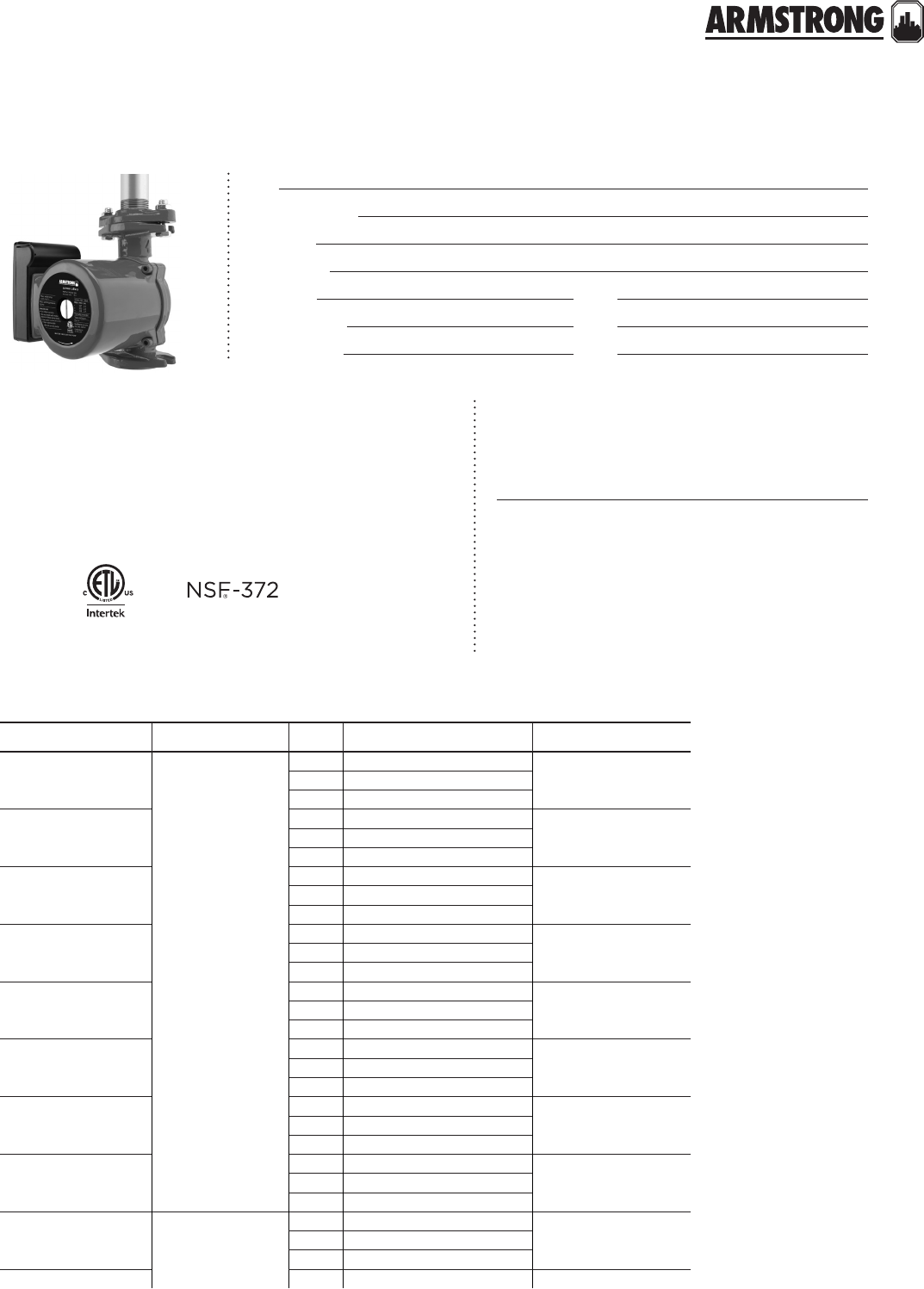
ASTRO 2 CIRCULATORS
THREE SPEED
|
SUBMITTAL
5
|
HYDRONIC SOLUTIONS CATALOG
Job:
Representative:
Engineer:
Contractor:
Order no: Date:
Submitted by: Date:
Approved by: Date:
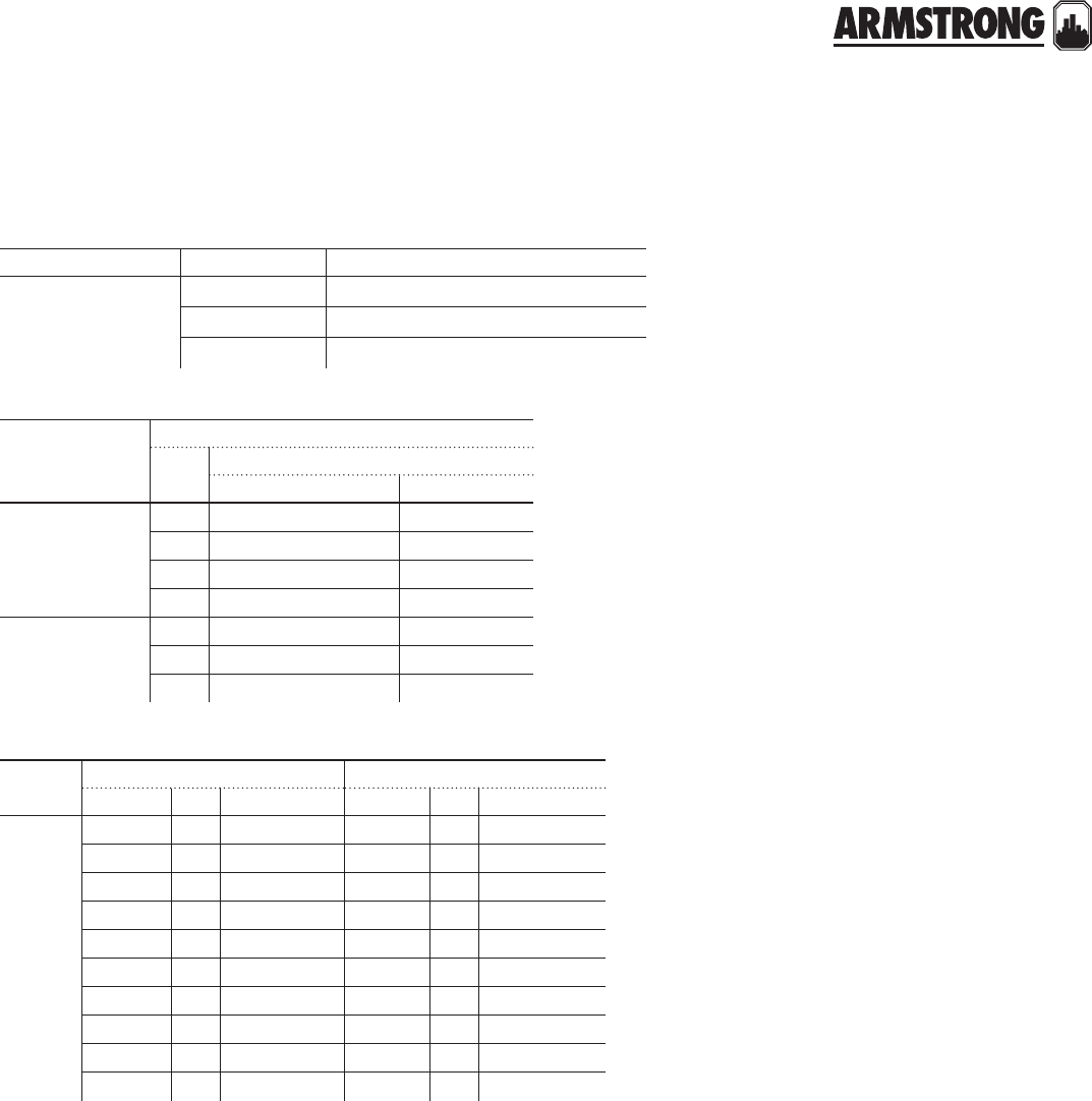
motor data
materials of construction
technical data
Flow range: 0 to 64 USgpm (0 to 4.04 L/s)
Head range: 0 to 42.0 feet (0 to 12.8 m)
Maximum fluid temperature: 185°f / 85°c (astro 286 up to 1.35a)
150°f / 65°c (astro 286 over 1.35a)
230°f / 110°c† (all others)
Maximum working pressure: 150 psi (1034 kPa)
Approvals: listed certified * Certified <0.25 weighted average percent lead and complies with
California Health and Safety Code Section 116875 (commonly known
as ab 1953).
Pump body: Cast iron (closed systems)
Lead free bronze* (open systems)
Stainless steel* (open systems)
Impeller: Noryl Shaft: Ceramic
Bearings: Ceramic Gasket material: epdm
model electrical input speed full load amp draw (a) nominal power (w)
Astro 210ci/ss
115v, 60hz
Single phase
31.06
200
21.50
11.72
Astro 220ssu
30.29
33
20.27
10.20
Astro 225bs
30.64
75
20.49
10.38
Astro 225ssu
30.69
83
20.55
10.43
Astro 230ss/ci/ci–r
30.81
97
20.58
10.45
Astro 250ss/ci/ci–r
30.98
117
20.79
10.65
Astro 280ci/ss
31.90
218
21.80
11.50
Astro 290ci/ss
31.90
218
21.60
11.40
Astro 280ci/ss 230v 230v, 60hz
Single phase
30.90
210
20.86
10.80
Astro 286ci/ss 11.60 370
† For open systems, it is recommended that the fluid temperature be less
than 150°f (66°c) to avoid precipitation of calcium.
back to
contents
<
ASTRO 2 CIRCULATORS
THREE SPEED
|
SUBMITTAL
6
|
HYDRONIC SOLUTIONS CATALOG
model part number
Astro 220ssu w½" swt 110223-301
Astro 220ssu w¾" swt 110223-302
Astro 220ssu 110223-309
Astro 225bs ½" swt 110223-303
Astro 225bs ¾" swt 110223-304
Astro 225ssu 110223-310
Astro 230ci 110223-305
Astro 230ci-r 110223-315
Astro 230ss 110223-306
model part number
Astro 250ci 110223-307
Astro 250ci-r 110223-317
Astro 250ss 110223-308
Astro 280ci 110223-320
Astro 280ss 110223-321
Astro 280ci (230v) 110223-322
Astro 280ss (230v) 110223-323
Astro 286ci (230v) 110223-324
Astro 286ss (230v) 110223-325
model part number
Astro 210ci 110223-326
Astro 210ss 110223-327
Astro 290ci 110223-328
Astro 290ss 110223-329
part numbers
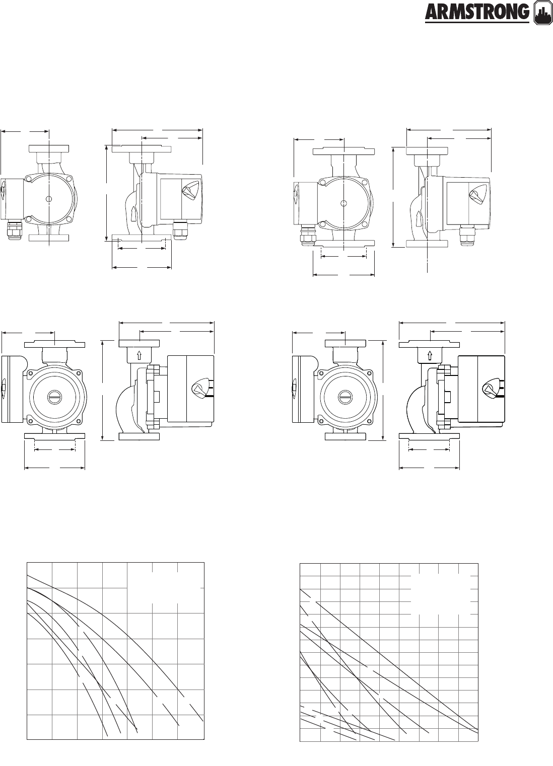
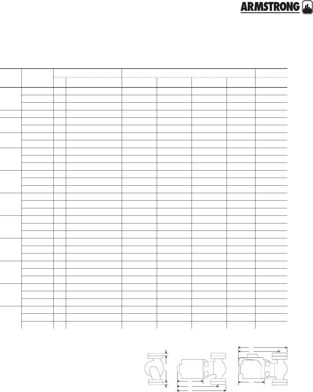
dimension data - inches (mm)
note: All dimensions are in inches (mm) and weights in lbs (kg).
** Removable check valve installed at pump outlet.
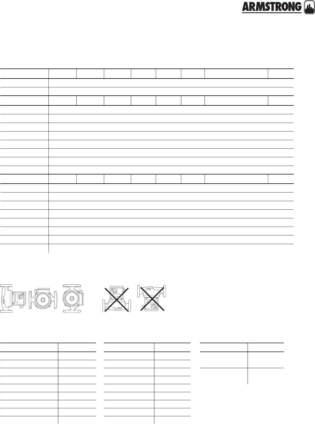
mounting orientation
right wrong
lead free bronze* a b c d e f connection type & size weight
Astro 225bs ½" swt 5.00 (127) 5.00 (127) 4.13 (105) —3.00 (76) —Sweat – ½" 6.0 (2.7)
Astro 225bs ¾" swt 5.00 (127) 5.00 (127) 4.13 (105) —3.00 (76) —Sweat – ¾" 6.0 (2.7)
stainless steel* a b c d e f connection type & size weight
Astro 220ssu** 6.00 (152) 5.00 (127) 4.00 (102) —3.00 (76) —Union – 1¼" npsm 6.5 (2.9)
Astro 225ssu** 6.00 (152) 5.00 (127) 4.00 (102) —3.00 (76) —Union – 1¼" npsm 6.5 (2.9)
Astro 230ss** 6.38 (162) 6.0 0 (150) 4.00 (102) 4.00 (102) 3.00 (76) 3.25 (80) Flange – (2) ½" dia. bolt holes 8.0 (3.6)
Astro 250ss** 6.38 (162) 6.00 (150) 4.00 (102) 4.00 (102) 3.00 (76) 3.25 (80) Flange – (2) ½" dia. bolt holes 8.0 (3.6)
Astro 210ss** 6.50 (165) 7.25 (184) 4.87 (124) 4.00 (102) 3.50 (90) 3.13 (80) Flange – (2) ½" dia. bolt holes 10.1 (4.6)
Astro 280ss (230v)** 6.50 (165) 6.75 (171) 4.87 (124) 4.00 (102) 3.50 (90) 3.13 (80) Flange – (2) ½" dia. bolt holes 10.1 (4.6)
Astro 286ss** 6.50 (165) 6.38 (162) 4.87 (124) 4.00 (102) 3.50 (90) 3.13 (80) Flange – (2) ½" dia. bolt holes 10.1 (4.6)
Astro 290ss** 8.50 (216) 6.65 (169) 5.20 (132) 4.00 (102) 3.50 (90) 3.45 (88) Flange – (2) ½" dia. bolt holes 13.2 (6.0)
cast iron a b c d e f connection type & size weight
Astro 230ci** 6.38 (162) 6.00 (150) 4.00 (102) 4.00 (102) 3.00 (76) 3.25 (80) Flange – (2) ½" dia. bolt holes 8.0 (3.6)
Astro 230ci-r** 6.38 (162) 5.63 (137) 4.00 (102) 4.00 (102) 3.00 (76) 3.25 (80) Flange – (2) ½" dia. bolt holes 8.0 (3.6)
Astro 250ci** 6.38 (162) 6.0 0 (150) 4.00 (102) 4.00 (102) 3.00 (76) 3.25 (80) Flange – (2) ½" dia. bolt holes 8.0 (3.6)
Astro 250ci-r** 6.38 (162) 5.63 (137) 4.00 (102) 4.00 (102) 3.00 (76) 3.25 (80) Flange – (2) ½" dia. bolt holes 8.0 (3.6)
Astro 210ci** 6.50 (165) 7.25 (184) 4.87 (124) 4.00 (102) 3.50 (90) 3.13 (80) Flange – (2) ½" dia. bolt holes 10.1 (4.6)
Astro 280ci (230v)** 6.50 (165) 6.38 (162) 4.87 (124) 4.00 (102) 3.50 (90) 3.13 (80) Flange – (2) ½" dia. bolt holes 10.1 (4.6)
Astro 286ci** 6.50 (165) 6.38 (162) 4.87 (124) 4.00 (102) 3.50 (90) 3.13 (80) Flange – (2) ½" dia. bolt holes 10.1 (4.6)
Astro 290ci** 8.50 (216) 6.65 (169) 5.20 (132) 4.00 (102) 3.50 (90) 3.45 (88) Flange – (2) ½" dia. bolt holes 13.2 (6.0)
ASTRO 2 CIRCULATORS
THREE SPEED
|
SUBMITTAL
7
|
HYDRONIC SOLUTIONS CATALOG
a
b
c
e
a
bc
e
astro 220ssu, 225ssu
astro 225bs
accessories
lead free* union fitting sets (contains two (2) half unions and gaskets)
model
flange kits
size item number
lead free bronze* cast iron
Astro
210/230/250
/280/286
Compass
0.75"816013-841 816013-111
1"816012-841 816012-111
1.25"816011-841 816011-111
1.5"816009-841 816009-111
Astro 290
1"806073-841 806073-111
1.25"804300-841 804300-111
1.5"804301-841 804301-111
model cif flex flanges
model size item number model size item number
All Astro
flange
models
cif-050t ½" 110124-100 ff-050t ½" 110124-200
cif-075t ¾" 110124-000 ff-075t ¾" 110124-201
cif-100t 1" 110124-001 ff-100t 1" 110124-202
cif-125t 1¼" 110124-002 ff-125t 1¼" 110124-203
cif-150t 1½" 110124-003 ff-150t 1½" 110124-204
cif-050s ½" 110124-150 ff-050s ½" 110124-250
cif-075s ¾" 110124-050 ff-075s ¾" 110124-251
cif-100s 1" 110124-051 ff-100s 1" 110124-252
cif-125s 1¼" 110124-052 ff-125s 1¼" 110124-253
cif-150s 1½" 110124-053 ff-150s 1½" 110124-254
model part number connection
Astro
220ssu/225ssu
810120-320 1.25" npsm × 0.5" sweat lead free
810120-322 1.25" npsm × 0.75" sweat lead free
810120-324 1.25" npsm × 0.75" fnpt lead free
ASTRO 2 CIRCULATORS
THREE SPEED
|
SUBMITTAL
8
|
HYDRONIC SOLUTIONS CATALOG
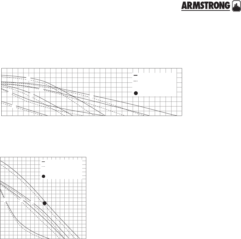
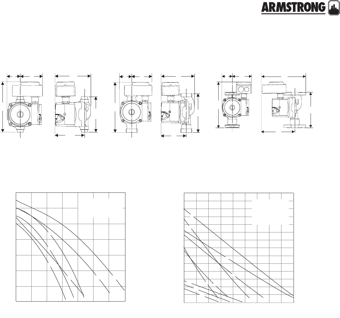
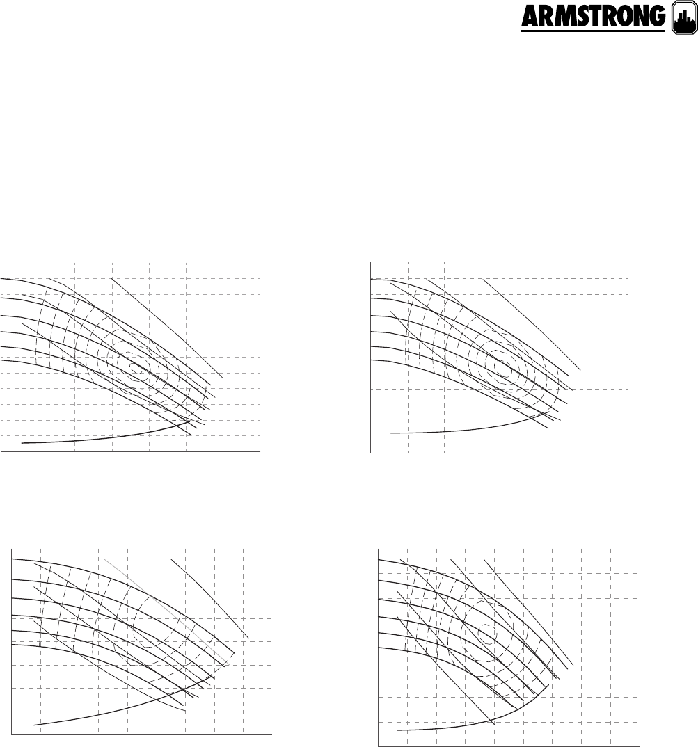
performance curve
astro 225bs, 225ssu astro 250, 230, 220
16
20
24
28
12
8
4
0
4.9
6.1
7.3
8.5
3.7
2.4
1.2
0
024681012141618
0 0.13 0.25 0.38 0.50 0.63 0.76 0.88 1.01 1.14
head - feet
head - metres
flow - usgpm
flow - l/s
astro 250
astro 230
astro 220
3
2
1
3
2
1
3
2
1
14
12
10
8
6
4
2
0
4.3
3.7
3.0
2.4
1.8
1.2
0.6
0
0246810 12 14
00.130.25 0.38 0.50 0.63 0.76 0.88
head - feet
head - metres
flow - usgpm
flow - l/s
astro 225bs
astro 225ssu
1 2 3
1
2
3
a
d
f
(on center)
bc
e
a
d
f
(on center)
bc
e
astro 230ci-r, 250ci-r
astro 230ss/ci, 250ss/ci
a
d
f
(on center)
bc
e
a
d
f
(on center)
bc
e
astro 280ci, 290ci/ss, 286ci/ss astro 280ss, 210ci/ss
ASTRO 2 CIRCULATORS
THREE SPEED
|
SUBMITTAL
9
|
HYDRONIC SOLUTIONS CATALOG
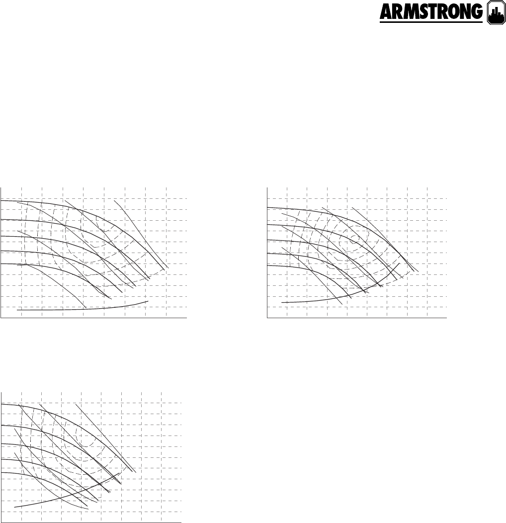
astro 280, 286
astro 210, 290
flow - usgpm
flow - l/s
16
24
32
40
44
8
0
0816 24 32 40
0 0.50 1.01 1.51 2.02 2.52
4.9
7.3
9.8
12.2
13.4
2.4
0
head - feet
head - metres
without check valve
with check valve
astro 280
astro 286
123
flow - usgpm
flow - l/s
12
16
20
8
4
00481216202428323644486064565240
0.250 0.50 0.76 1.01 1.26 1.51 1.77 2.02 2.27 2.78 3.03 3.79 4.043.533.282.52
3.7
4.9
6.1
2.4
1.2
0
head - feet
head - metres
without check valve
with check valve
astro 290
astro 210
12
3
1
2
3
10
|
HYDRONIC SOLUTIONS CATALOG
ASTRO 2
|
HOT WATER RE-CIRCULATION SYSTEMS
SUBMITTAL
11
|
HYDRONIC SOLUTIONS CATALOG
Power connection: 6.0 ft. (1.8 m) power cord, molded duplex
plug with ground
Environment: Indoor use only
Flow range: 0 to 64 USgpm (0 to 4.04 L/s)
Head range: 0 to 42.0 feet (0 to 12.8 m)
Max. working pressure: 150 psi (1034 kPa)
Max. water temperature: 230°f (110°c)†
Ambient temperature: 39°f (4°c) to 104°f (40°c)
Low temperature switchpoint1: 85°f (29°c) ± 10%
High temperature switchpoint1: 105°f (40°c) ± 10%
Clock/timer: 12 hour analog clock with am/pm indication
Timer settings: Individual mechanical toggles for each 15
minute interval over 24 hours
Manual override: Three position slide switch; on/auto/o
Approvals: listed certified
Job:
Representative:
Engineer:
Contractor:
Order no: Date:
Submitted by: Date:
Approved by: Date:
materials of construction
* Certified <0.25 weighted average percent lead and complies with California
Health and Safety Code Section 116875 (commonly known as ab 1953).
Pump body: Lead free bronze* (bs models)
Stainless steel* (ss models)
Impeller: Noryl Shaft: Ceramic
Bearings: Ceramic Gasket material: epdm
1 High/low temperature switchpoints are as measured on pipe surface with the
Aquastat (ta models only).
† For open systems, it is recommended that the fluid temperature be less
than 150°f (66°c) to avoid precipitation of calcium.
technical data
pump design data
Pump model: Flange size:
No. of pumps: Note:
Capacity: USgpm (L/s) Temperature: °f (°c)
Head: ft (m) Liquid:
Companion flanges: Included:
application
Armstrong Astro 2 hot water re-circulation systems
automatically circulate water through domestic hot water
distribution pipes. This helps to ensure that everyone in the
household has ‘instant’ hot water at the tap when they need
it, while also helping to conserve water and save water heat-
ing energy costs. All systems are assembled, wired, tested
and then shipped, ready for installation.
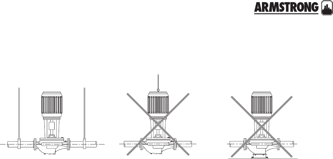
mounting orientation
model electrical
input speed
full load
amp
draw (a)
nominal
power (w)
astro
220ssu
115v, 60hz
Single phase
3 0.29
33
2 0.27
1 0.20
astro
225bs
3 0.64
752 0.49
1 0.38
astro
225ssu
3 0.69
832 0.55
1 0.43
astro
230ss
3 0.81
972 0.58
1 0.45
astro
250ss
3 0.98
117
2 0.79
1 0.65
motor data
right wrong
back to
contents
<
ASTRO 2
|
HOT WATER RE-CIRCULATION SYSTEMS
SUBMITTAL
12
|
HYDRONIC SOLUTIONS CATALOG
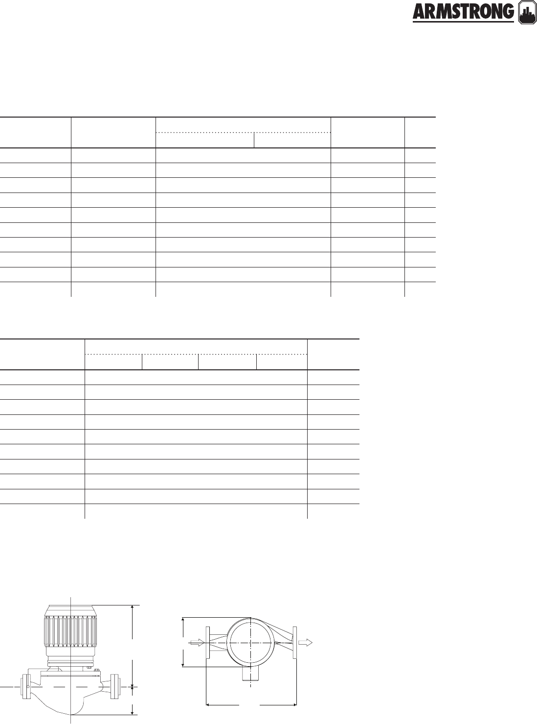
dimension data - inches (mm)
note: All dimensions are in inches (mm)
model connection size cord timer aquastat
electrical
data @ 115
Vac, 60 Hz
weight part
number
astro 220ssu050s-ta* Sweat ½" ü ü ü 0.29 A, 33W 7.50 (3.40) 110223-140
astro 220ssu075s-ta* Sweat ¾" ü ü ü 0.29 A, 33W 7.50 (3.40) 110223-141
astro 225bs050s-ta Sweat ½" ü ü ü 0.64 A, 75W7.00 (3.18) 110223-142
astro 225bs075s-ta Sweat ¾" ü ü ü 0.64 A, 75W7.00 (3.18) 110223-143
astro 220ssu-ta npsm union 1¼" ü ü ü 0.29 A, 33W 7.50 (3.40) 110223-144
astro 225ssu-ta npsm union 1¼" ü ü ü 0.69 A, 83W7.50 (3.40) 110223-145
astro 230ss-ta 2 bolt flange 2 bolt flange ü ü ü 0.81 A, 97W10.00 (4.54) 110223-148
astro 250ss-ta 2 bolt flange 2 bolt flange ü ü ü 0.98 A, 117W10.00 (4.54) 110223-149
astro 220ssu050s-t* Sweat ½" ü ü — 0.29 A, 33W 7.50 (3.40) 110223-240
astro 220ssu075s-t* Sweat ¾" ü ü — 0.29 A, 33W 7.50 (3.40) 110223-241
astro 225bs050s-t Sweat ½" ü ü — 0.64 A, 75W7.00 (3.18) 110223-242
astro 225bs075s-t Sweat ¾" ü ü — 0.64 A, 75W7.00 (3.18) 110223-243
astro 220ssu-t npsm union 1¼" ü ü — 0.29 A, 33W 7.50 (3.40) 110223-244
astro 225ssu-t npsm union 1¼" ü ü — 0.69 A, 83W7.50 (3.40) 110223-245
astro 230ss-t 2 bolt flange 2 bolt flange ü ü — 0.81 A, 97W10.00 (4.54) 110223-248
astro 250ss-t 2 bolt flange 2 bolt flange ü ü — 0.98 A, 117W10.00 (4.54) 110223-249
astro 220ssu050s-lc* Sweat ½" ü— — 0.29 A, 33W 7.00 (3.18) 110223-340
astro 220ssu075s-lc* Sweat ¾" ü— — 0.29 A, 33W 7.00 (3.18) 110223-341
astro 225bs050s-lc Sweat ½" ü— — 0.64 A, 75W6.50 (2.95) 110223-342
astro 225bs075s-lc Sweat ¾" ü— — 0.64 A, 75W6.50 (2.95) 110223-343
astro 220ssu-lc npsm union 1¼" ü— — 0.29 A, 33W 7.00 (3.18) 110223-344
astro 225ssu-lc npsm union 1¼" ü— — 0.69 A, 83W7.00 (3.18) 110223-345
astro 230ss-lc 2 bolt flange 2 bolt flange ü— — 0.81 A, 97W9.00 (4.08) 110223-348
astro 250ss-lc 2 bolt flange 2 bolt flange ü— — 0.98 A, 117W9.00 (4.08) 110223-349
note: All weights are in lbs. (kg) *Union model with sweat hardware kit.
model a b c d e f
astro 225bs 5.0 (127) 6.5 (165) 5.6 (142) 7.1 (180) 4.3 (110) 1.8 (46)
astro 220/225ssu 5.0 (127) 5.3 (134) 4.4 (112) 6.3 (160) 3.4 (86) 1.8 (46)
astro 230/250ss 6.4 (162) 8.7 (221) 6.8 (173) 7.0 (178) 3.7 (93) 1.8 (46)
accessories
24 hour timer
model part number
24 hour timer 810123-130
See page 49 for the details on 24-Hour Timer
aquastat
model part number
½" 110123-120
¾" 110123-121
See Page 85 for the details on Aquastat models.
ASTRO 2
|
HOT WATER RE-CIRCULATION SYSTEMS
SUBMITTAL
13
|
HYDRONIC SOLUTIONS CATALOG
model cif flex flanges
model size item number model size item number
All Astro
flange
models
cif-050t ½" 110124-100 ff-050t ½" 110124-200
cif-075t ¾" 110124-000 ff-075t ¾" 110124-201
cif-100t 1" 110124-001 ff-100t 1" 110124-202
cif-125t 1¼" 110124-002 ff-125t 1¼" 110124-203
cif-150t 1½" 110124-003 ff-150t 1½" 110124-204
cif-050s ½" 110124-150 ff-050s ½" 110124-250
cif-075s ¾" 110124-050 ff-075s ¾" 110124-251
cif-100s 1" 110124-051 ff-100s 1" 110124-252
cif-125s 1¼" 110124-052 ff-125s 1¼" 110124-253
cif-150s 1½" 110124-053 ff-150s 1½" 110124-254
lead free* union fitting sets (contains two (2) half unions and gaskets)
model
flange kits
size item number
lead free bronze* cast iron
Astro
210/230/250
/280/286
Compass
0.75"816013-841 816013-111
1"816012-841 816012-111
1.25"816011-841 816011-111
1.5"816009-841 816009-111
Astro 290
1"806073-841 806073-111
1.25"804300-841 804300-111
1.5"804301-841 804301-111
model part number connection
Astro 220ssu/225ssu
810120-320 1.25" npsm × 0.5" sweat lead free
810120-322 1.25" npsm × 0.75" sweat lead free
810120-324 1.25" npsm × 0.75" fnpt lead free
ASTRO 2
|
HOT WATER RE-CIRCULATION SYSTEMS
SUBMITTAL
14
|
HYDRONIC SOLUTIONS CATALOG
astro 225bs astro 230/250ssastro 220/225ssu
b
c
a
d
fe
b
c
a
d
f
e
b
c
a
d
f
e
performance curve
astro 225bs, 225ssu astro 250, 230, 220
16
20
24
28
12
8
4
0
4.9
6.1
7.3
8.5
3.7
2.4
1.2
0
024681012141618
0 0.13 0.25 0.38 0.50 0.63 0.76 0.88 1.01 1.14
head - feet
head - metres
flow - usgpm
flow - l/s
astro 250
astro 230
astro 220
3
2
1
3
2
1
3
2
1
14
12
10
8
6
4
2
0
4.3
3.7
3.0
2.4
1.8
1.2
0.6
0
0246810 12 14
00.130.25 0.38 0.50 0.63 0.76 0.88
head - feet
head - metres
flow - usgpm
flow - l/s
astro 225bs
astro 225ssu
1 2 3
1
2
3
ASTRO 2
|
24 HOUR TIMER
|
SUBMITTAL
15
|
HYDRONIC SOLUTIONS CATALOG
Job:
Representative:
Engineer:
Contractor:
Order no: Date:
Submitted by: Date:
Approved by: Date:
a
b
c
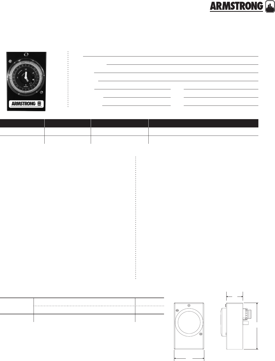
Armstrong 24 hour timers provide on/o pump control
according to preset operating times in order to increase
occupant comfort and improve the overall eciency
of domestic hot water re-circulation systems. The 24
hour timers are designed only for use with specified
Armstrong Astro series wet rotor circulators installed in
indoor hot water re-circulation applications.
Typical timer applications will cycle the pump at preset
times, allowing the user to select operation of the circu-
lating pump during high peak usage periods in order to
decrease the delivery time to outlet fixtures and reduce
wasted water.
The timer control is programmable to ¼ hour intervals
within a 24 hour time frame utilizing a user-friendly
analog clock timer with hour and minute hands, two
directional arrows, and am/pm time setting.
Description: 24 hour timer
Application: Time actuated on/o pump control
Shortest switching interval: ¼ hour (15 minutes)
Manual switch modes: Timer, on override, o override
Ambient temperature range: -40°f to 180°f (-40°c to 82°c)
Power consumption: 120 v, 0.5 w
Supply voltage: 110-120 vac, 60 Hz
Terminals: ¼" spade terminals
Switch rating: Type: Spot
Resistive: 21a
Tungsten: 1350 w
Inductive: 1 hp @ 120 vac; 2 hp @ 240 vac
24 hour timer: 810123-130
quantity tag no. model no. comments
technical data application
part numbers
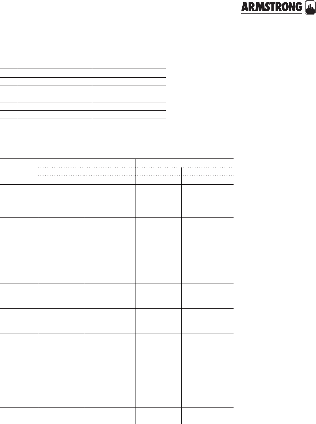
dimension data - inches (mm)
model dimensions inches (mm) weight
a b c lbs (oz.)
24 hour timer 2.74 (70) 1.50 (38) 4.23 (107) 0.19 (3.0)
back to
contents
<
16
|
HYDRONIC SOLUTIONS CATALOG

17
|
HYDRONIC SOLUTIONS CATALOG
AQUASTAT CONTROLS
½” & ¾”
|
SUBMITTAL
Job:
Representative:
Engineer:
Contractor:
Order no: Date:
Submitted by: Date:
Approved by: Date:
technical data
Description: Aquastat (thermostatic) switch
Application: Clip-on thermostatic control for Astro circulators
Type: Bi-metallic disc, snap-acting
Enclosure: Environmentally sealed
Mounting: Clip-on mount for ½" (12.7 mm) i.d. copper tube [X" (15.8 mm) o.d.]
Clip on mount for ¾" (19.0 mm) i.d. copper tube [Y" (22.2 mm) o.d.]
Contact rating: 10 a @ 120 v, 60 Hz resistive; 5 a @ 240 v, 60 Hz resistive
Temperature Rating* : 105±5°f (40±2°c) pump switches o
85±6°f (29±3°c) pump switches on
Leads: 2 Leads, awg 18, 14" (356 mm)
12" (305 mm), black insulation, silicon or epoxy overmold
½" (12.7 mm) strip length
* Temperatures indicated are at pipe surface
a
b
j
h
g
f
e
d
c
model dimensions inches (mm)
a b c d e f g h j
½" Aquastat 0.56
(14.2)
1.12
(28.4)
0.625 (15.8)
nominal pipe o.d.
1.7
(43.2)
0.96
(24.4)
1.04
(26.4)
14.0
(355.6)
2.0
(50.8)
0.5
(12.7)
¾" Aquastat 0.56
(14.2)
1.12
(28.4)
0.875 (22.2)
nominal pipe o.d.
1.8
(45.7)
0.96
(24.4)
1.04
(26.4)
14.0
(355.6)
2.0
(50.8)
0.5
(12.7)
dimension data - inches (mm)
part numbers
model part numer
½" Aquastat 110123-120
¾" Aquastat 110123-121
back to
contents
<
18
|
HYDRONIC SOLUTIONS CATALOG
AQUASTAT CONTROLS
½” & ¾”
|
SUBMITTAL
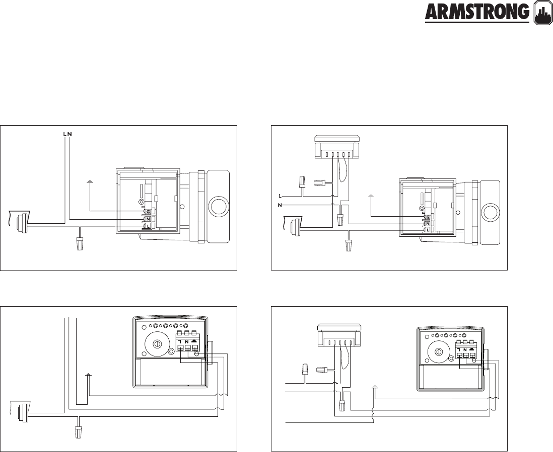
wiring diagram
54321
astro series circulator with 24 hour timer and aquastat control wiring diagram
ground
screw
pump
white
black
black
black
white
white
aquastat
black
black
white
black
green
timer
astro 2 series circulator and 24 hour timer wiring diagram
green
ground screw
in timer box
white
black
black
black
white
black
white
black
green
green
timer
G
N
L
astro series circulator with aquastat control wiring diagram
pump
white
white
aquastat
black
black
green
GNL
astro 2 series circulator with aquastat control wiring diagram
pump
white
white
aquastat
black
black
green
ASTRO EXPRESS 2
HOT WATER RECIRCULATION
|
SUBMITTAL
19
|
HYDRONIC SOLUTIONS CATALOG
Environment: Indoor use only
Max. working pressure: 100 psi (689 kPa)
Max. water temperature: 140°f (60°c)
Approvals: listed certified
Job:
Representative:
Engineer:
Contractor:
Order no: Date:
Submitted by: Date:
Approved by: Date:
quantity description
*Astro Express 2 system (Wet rotor circulator
with timer, line cord, union hardware, and one
Astro Express lf valve)
*Astro Express lf valve (only) for lengthy
branches to additional faucets o main
distribution pipe
technical data
astro express 2 circulator
astro express 2 circulator
astro express lf valve
Power requirements: 115 vac, 60 Hz, 33 w, 0.29 a max.
Max. head (Astro 220ssu): 5.3 ft (1.6 m)
Max. flow (Astro 220ssu): 10.0 gpm (0.63 L/s)
Ambient temperature: 39°f (4°c) to 104°f (40°c)
Clock timer: 12 hour analog clock with am/pm indication
Timer settings: Individual toggles for each 15 minute
interval over 24 hours
Manual override: 3 position slide switch, on/o/auto
Housing: Forged eco brass* with noryl cap
Internal components: Stainless steel and plastic with
epdm o-rings
Connections: Threaded, ½" hot & cold inlets, W" hot
& cold outlets
Flowrate adjustment: 0 – 100%, multi-turn slotted screw
Mounting: Plastic wall anchor with screw
materials of construction
mounting orientation
performance curve
Pump casing: Astro 220ssu with 1¼” npsm union threads
Power connection: 6.0 ft (1.8 m) power cord, molded duplex
plug with ground
Impeller: pa66
Shaft: Ceramic
Bearings/seal: Ceramic/epdm
Union tailpieces: Brass, ¾" fpt (two) and ¾" mpt (one)
Union gaskets: epdm (two)
Connect the hot and cold water supply to the Astro
Express lf valve K" threaded inlets. (Stainless steel flex
hose recommended.)
Connect the hot and cold Astro Express lf valve W"
threaded outlets to the faucet. (Stainless steel flex hose
recommended.)
Secure the valve to the wall under the sink, using the plastic
wall anchor and screw.
*Complies with Section 116875 of the California Health and Safety Code and
Vermont Act 193. (Lead content of all wetted surface is 0.25% or less.)
5
5.5
4
3
2
1
00246810
12
head - feet
flow - usgpm
1
2
3
back to
contents
<
ASTRO EXPRESS 2
HOT WATER RECIRCULATION
|
SUBMITTAL
20
|
HYDRONIC SOLUTIONS CATALOG
part numbers
product dimensions inches (mm) weight
a b c d e f g lbs (kg)
Astro Express
2 circulator 6.00(152) 5.00 (127) 4.00 (102) —5.00 (127) 1.80 (46) —10.00 (4.45)
Astro Express
lf valve 2.50 (63) 1.50 (38) 2.10 (53) 2.60 (66) 0.80 (20) W"ips K" ips 0.50 (0.23)
dimension data - inches (mm)
model part numer
Astro Express 2 circulator 110223-401
Astro Express lf valve 561100LF-001
ef
b
c
a
supply
cold
c
b
d
f
e
a
g
hot
cold
faucet
hot
astro express 2 circulatorastro express lf valve
product part no.
Astro Express lf valve 561100LF-001 See page 84 for the details on Astro Express lf valve
Timer 810123-130 See page 49 for the details on 24 hour timer
Union kits
(Lead free brass*)
810120-320
See page 181 for the details on Union Fitting Sets810120-322
810120-324
replacements parts
S&H 3-PIECE CIRCULATORS
S MODELS
|
SUBMITTAL
21
|
HYDRONIC SOLUTIONS CATALOG
Job:
Representative:
Engineer:
Contractor:
Order no: Date:
Submitted by: Date:
Approved by: Date:
materials of construction
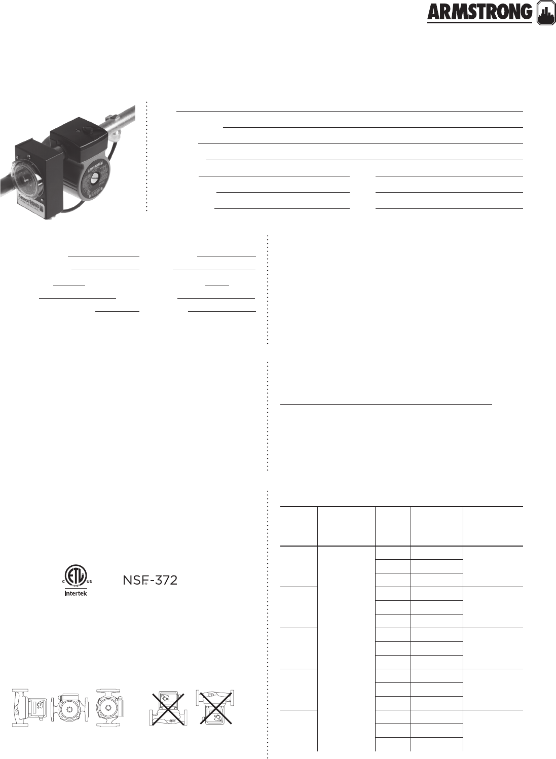
ma ximum pump oper ating cond itions
125 psig at 225°f (863 kPa at 107°c)
p
referred selection are
a
Based on 1800 rpm, 60 Hz motors. For 50 Hz motors write for special capacity charts.
flow - usgpm
flow - l/s
head - feet
head - meters
0 0.63 1.89 3.15 4.41 5.68 6.94 8.209.4610.73
01030507090 110 130 150 170
0
5
10
15
20
25
30
35
40
0
1.5
3.0
4.6
6.1
7.6
9.1
10.7
12.1
S2
S4
S3
S5
S4
S6
S5
Based on 1800 rpm, 60 Hz
motors. For 50 Hz motors
write for special capacity charts.
performance curve
The pump should be installed in a position to
permit proper lubrication of bearings and servicing.
Motor and bearing bracket are to be kept free
of insulation. Pump and motor unit are designed
to be supported by the in line piping only. Do
not support in any other manner. A height of
approximately 4 feet above floor is recommended.
mounting orientation
horizontal mounting
part name bronze fitted lead free bronze*
Pump Body Cast iron Lead free Bronze
Impeller: Non-ferrous
Bearings: Sleeve - Oil lubricated**
Maintenance free - Permanently lubricated***
Seal: Mechanical
Stationary seal face: Sintered silicon carbide
Coupler: s25-s46: Flexible, 4 - Spring;
s55-s69: Flexible spacer type
Motor: Single phase - 1800 rpm - Resilient mounted
Three phase - 1800 rpm - Resilient mounted
* Contains less than 0.25% lead, weighted average.
** Alloy shaft with copper sleeve.
*** Stainless steel shaft.
back to
contents
<
S&H 3-PIECE CIRCULATORS
S MODELS
|
SUBMITTAL
22
|
HYDRONIC SOLUTIONS CATALOG
Dimensions shown are for reference only. For exact dimensional data,
contact factory.
Companion flanges are not furnished as standard on s-25, s-45 and h-32.
Conduit box not supplied on K hp or greater.
** All single phase motors are equipped with a built-in thermal overload
protection. Three phase motors require external overload protection.
b
d
dk
c
a
c
a
k
resilient mountend view side view
model
standard design maintenance free design
bronze fitted lead free* bronze bronze fitted lead free* bronze
item no. item no. item no. item no.
S25 174031-013 174031LF-043 174031MF-013 174031MF-043
S35 174033-013 174033LF-043 174033MF-013 174033MF-043
S45 174036-113 174036LF-143 174036MF-113 174036MF-143
S46 174037-113 174037LF-143 174037MF-113 174037MF-143
S55 (1 Phase) 106284-132 106284LF-133 106284MF-132 106284MF-133
S55 (3 Phase) 106284-136 106284LF-137 106284MF-136 106284MF-137
S55 (3 pH 575 V) 106284-010 106284LF-011 106284MF-010 106284MF-011
S57 (1 Phase) 106285-132 106285LF-133 106285MF-132 106285MF-133
S57 (3 Phase) 106285-136 106285LF-137 106285MF-136 106285MF-137
S57 (3 pH 575 V) 106285-010 106285LF-011 106285MF-010 106285MF-011
S69 (1 Phase) 116531-132 116532LF-133 n/a n/a
S69 (3 Phase) 116535-136 116536LF-137 n/a n/a
S69 (3 pH 575 V) 116539-000 116540LF-000 n/a n/a
part numbers
dimension data - inches (mm)
model flange
size (n.p.t)
motor** dimensions inches (mm) weight
hp phase and volt a b c d lbs (kg)
S25
OA⁄ab 1 phase 115 v 13.75 (349) 6.50 (165) 11.50 (292) 0.75 (19) 19 (8.6)
1A⁄ab 1 phase 115 v 13.75 (349) 6.50 (165) 11.50 (292) 0.75 (19) 19 (8.6)
1N A⁄ab 1 phase 115 v 13.75 (349) 6.50 (165) 11.50 (292) 0.88 (22) 19 (8.6)
1K A⁄ab 1 phase 115 v 13.75 (349) 6.50 (165) 11.50 (292) 0.88 (22) 19 (8.6)
S35 2 T 1 phase 115 v 15.00 (581) 8.50 (216) 12.50 (318) 0.88 (22) 38 (17.2)
S45 2K N 1 phase 115 v 15.75 (400) 10.00 (254) 12.50 (318) 1.00 (25) 45 (20.4)
3 N 1 phase 115 v 15.75 (400) 10.00 (254) 12.50 (318) 1.00 (25) 45 (20.4)
S46 3 L 1 phase 115 v 15.75 (400) 10.00 (254) 12.50 (318) 1.00 (25) 51 (23.1)
S55
3 K 1 phase 115/230 v19.50 (495) 12.00 (305) 16.00 (406) 1.00 (25) 82 (37.2)
3 K 3 phase 208-230/460 v 19.50 (495) 12.00 (305) 16.00 (406) 1.00 (25) 74 (33.6)
3 K 3 phase 575 v 19.50 (495) 12.00 (305) 16.00 (406) 1.00 (25) 74 (33.6)
S57
3 O 1 phase 115/230 v20.00 (508) 12.00 (305) 16.50 (419) 1.00 (25) 82 (37.2)
3 O 3 phase 208-230/460 v 20.00 (508) 12.00 (305) 16.50 (419) 1.00 (25) 76 (34.5)
3 O 3 phase 575 v 20.00 (508) 12.00 (305) 16.50 (419) 1.00 (25) 76 (34.5)
S69
3 1 1 phase 115/230 v25.00 (635) 14.25 (362) 20.25 (514) 1.00 (25) 130 (59.0)
3 1 3 phase 208-230/460 v 25.00 (635) 14.25 (362) 20.25 (514) 1.00 (25) 125 (56.7)
3 1 3 phase 575 v 25.00 (635) 14.25 (362) 20.25 (514) 1.00 (25) 125 (56.7)
note:
standard design circulators are with
Sleeve Bearing sba and maintenance
free design circulators are with ball
bearing sba.

S&H 3-PIECE CIRCULATORS
S MODELS
|
SUBMITTAL
23
|
HYDRONIC SOLUTIONS CATALOG
companion single flange part numbers
size cast iron lf bronze
O116013-011 116013-841
1116012-011 116012-841
1N 116011-011 116011-841
1K 116009-011 116009-841
2105210-011/106074-011 105210-841/106074-841
2K 105189-011 105189-841
3105188-011/133615-010 105188-841/106466-841
24
|
HYDRONIC SOLUTIONS CATALOG
S&H 3-PIECE CIRCULATORS
H MODELS
|
SUBMITTAL
25
|
HYDRONIC SOLUTIONS CATALOG
Job:
Representative:
Engineer:
Contractor:
Order no: Date:
Submitted by: Date:
Approved by: Date:
The pump should be installed in a position to permit proper
lubrication of bearings and servicing. Motor and bearing
bracket are to be kept free of insulation. Pump and motor
unit are designed to be supported by the in line piping
only. Do not support in any other manner. A height of
approximately 4 feet above floor is recommended.
materials of construction
ma ximum pump oper ating conditio ns
mounting orientation
125 psig at 225°f (863 kPa at 107°c)
Based on 1800 rpm, 60 Hz motors. For 50 Hz motors write for special capacity charts.
flow - usgpm
flow - l/s
head - feet
head - metres
0 0.63 1.89 3.15 4.41 5.68 6.94 8.209.4610.73
01030507090 110 130 150 170
0
10
20
30
50
40
0
3.0
6.1
9.1
15.2
12.1
H5
H4
H6
H6
H6
H6
H6
H6
H5
H5
H5
H3
Based on 1800 rpm, 60 Hz
motors. For 50 Hz motors write
for special capacity charts.
performance curve
horizontal mounting
part name h-32 to h-54
bronze fitted
h-63 to h-68
bronze fitted
h-32 to h-54
lead free bronze*
h-63 to h-68
lead free bronze*
Pump body Cast iron Cast iron Lead free bronze Lead free bronze
Coupler h-32 & h-41 flexible, 4-spring
h-51 to h-54 flexible, spacer type Flexible, spacer type h-32 & h-41 flexible, 4-spring
h-51 to h-54 flexible, spacer type Flexible, spacer type
Impeller: Non-ferrous
Bearings: Sleeve - Oil lubricated**
Maintenance free - Permanently lubricated***
Seal: Mechanical
Stationary seal face: Sintered silicon carbide
* Contains less than 0.25% lead, weighted average.
** Alloy shaft with copper sleeve.
*** Stainless steel shaft.
S&H 3-PIECE CIRCULATORS
H MODELS
|
SUBMITTAL
26
|
HYDRONIC SOLUTIONS CATALOG
Dimensions shown are for reference only. For exact dimensional data,
contact factory.
Companion flanges are not furnished as standard on s-25, s-45 and h-32.
Conduit box not supplied on K hp or greater.
** All single phase motors are equipped with a built-in thermal overload
protection. Three phase motors require external overload protection. b
d
dk
c
a
c
a
k
resilient mountend view side view
dimension data - inches (mm)
model flange
size (n.p.t)
motor** dimensions inches (mm) weight
hp phase and volt a b c d lbs (kg)
H32
1 T 1 phase 115 v15.00 (381) 8.50 (216) 12.50 (318) 0.88 (22) 30 (13.6)
1N T 1 phase 115 v15.00 (381) 8.50 (216) 12.50 (318) 0.88 (22) 30 (13.6)
1K T1 phase 115 v15.00 (381) 8.50 (216) 12.50 (318) 0.88 (22) 30 (13.6)
H41 1 T 1 phase 115 v15.25 (387) 8.50 (216) 12.50 (318) 0.75 (19) 34 (15.4)
H51 1 N 1 phase 115 v 17.25 (438) 11.50 (292) 13.50 (343) 0.75 (19) 48 (21.8)
1 N 3 phase 208-230/460 v 17.25 (438) 11.50 (292) 13.50 (343) 0.75 (19) 48 (21.8)
H52 1N L 1 phase 115 v 17.25 (438) 11.50 (292) 13.50 (343) 0.88 (22) 48 (21.8)
1N L 3 phase 208-230/460 v 17.25 (438) 11.50 (292) 13.50 (343) 0.88 (22) 48 (21.8)
H53
1K K 1 phase 115 v 20.00 (508) 11.50 (292) 16.50 (419) 0.88 (22) 58 (26.3)
1K K 3 phase 208-230/460 v 20.00 (508) 11.50 (292) 16.50 (419) 0.88 (22) 58 (26.3)
1K K 3 phase 575 v 20.00 (508) 11.50 (292) 16.50 (419) 0.88 (22) 58 (26.3)
H54
2 O 1 phase 115 v 20.00 (508) 11.50 (292) 16.50 (419) 0.88 (22) 68 (30.8)
2 O 3 phase 208-230/460 v 20.00 (508) 11.50 (292) 16.50 (419) 0.88 (22) 68 (30.8)
2 O 3 phase 575 v 20.00 (508) 11.50 (292) 16.50 (419) 0.88 (22) 68 (30.8)
H63
1K K 1 phase 115 v 23.00 (584) 13.50 (343) 19.75 (502) 0.88 (22) 86 (39.0)
1K K 3 phase 208-230/460 v 23.00 (584) 13.50 (343) 19.75 (502) 0.88 (22) 86 (39.0)
1K K 3 phase 575 v 23.00 (584) 13.50 (343) 19.75 (502) 0.88 (22) 86 (39.0)
H64
1K O 1 phase 115 v 23.00 (584) 13.50 (343) 19.75(502) 0.88 (22) 89 (40.4)
1K O 3 phase 208-230/460 v 23.00 (584) 13.50 (343) 19.75(502) 0.88 (22) 89 (40.4)
1K O 3 phase 575 v 23.00 (584) 13.50 (343) 19.75(502) 0.88 (22) 89 (40.4)
H65
1K 1 1 phase 115 v 23.00 (584) 13.50 (343) 19.75(502) 0.88 (22) 92 (41.7)
1K 1 3 phase 208-230/460 v 23.00 (584) 13.50 (343) 19.75(502) 0.88 (22) 92 (41.7)
1K 1 3 phase 575 v 23.00 (584) 13.50 (343) 19.75(502) 0.88 (22) 92 (41.7)
H66
2 O 1 phase 115 v 23.25 (591) 14.00 (356) 19.75 (502) 0.88 (22) 110 (49.9)
2 O 3 phase 208-230/460 v 23.25 (591) 14.00 (356) 19.75 (502) 0.88 (22) 110 (49.9)
2 O 3 phase 575 v 23.25 (591) 14.00 (356) 19.75 (502) 0.88 (22) 110 (49.9)
H67
2 1 1 phase 115 v 23.25 (591) 14.00 (356) 19.75 (502) 0.88 (22) 115 (52.1)
2 1 3 phase 208-230/460 v 23.25 (591) 14.00 (356) 19.75 (502) 0.88 (22) 115 (52.1)
2 1 3 phase 575 v 23.25 (591) 14.00 (356) 19.75 (502) 0.88 (22) 115 (52.1)
H68
2 1K 1 phase 115 v 21.75 (552) 14.00 (356) 18.25 (464) 0.88 (22) 120 (54.0)
2 1K 3 phase 208-230/460 v 21.75 (552) 14.00 (356) 18.25 (464) 0.88 (22) 120 (54.0)
2 1K 3 phase 575 v 21.75 (552) 14.00 (356) 18.25 (464) 0.88 (22) 120 (54.0)
S&H 3-PIECE CIRCULATORS
H MODELS
|
SUBMITTAL
27
|
HYDRONIC SOLUTIONS CATALOG
model
standard design maintenance free design
bronze fitted lead free* bronze bronze fitted lead free* bronze
item no. item no. item no. item no.
H32 174034-013 174034LF-043 174034MF-013 174034MF-043
H41 174035-113 174035LF-143 174035MF-113 174035MF-143
H51 (1 Phase) 116431-132 116432LF-133 116431MF-132 116432MF-133
H51 (3 Phase) 110119-100 110119LF-101 110119MF-100 110119MF-101
H52 (1 Phase) 116435-132 116436LF-133 116435MF-132 116436MF-133
H52 (3 Phase) 110119-102 110119LF-103 110119MF-102 110119MF-103
H53 (1 Phase) 116439-132 116440LF-133 116439MF-132 116440MF-133
H53 (3 Phase) 116443-136 116444LF-137 116443MF-136 116444MF-137
H53 (3 pH 575 V) 116447-000 116448LF-000 116447MF-000 116448MF-000
H54 (1 Phase) 116451-132 116452LF-133 116451MF-132 116452MF-133
H54 (3 Phase) 116455-136 116456LF-137 116455MF-136 116456MF-137
H54 (3 pH 575 V) 116459-000 116460LF-000 116459MF-000 116460MF-000
H63 (1 Phase) 116463-132 116464LF-133 n/a n/a
H63 (3 Phase) 116467-136 116468LF-137 n/a n/a
H63 (3 pH 575 V) 116471-000 116472LF-000 n/a n/a
H64 (1 Phase) 116475-132 116476LF-133 n/a n/a
H64 (3 Phase) 116479-136 116480LF-137 n/a n/a
H64 (3 pH 575 V) 116483-000 116484LF-000 n/a n/a
H65 (1 Phase) 116487-132 116488LF-133 n/a n/a
H65 (3 Phase) 116491-136 116492LF-137 n/a n/a
H65 (3 pH 575 V) 116495-000 116496LF-000 n/a n/a
H66 (1 Phase) 116499-132 116500LF-133 n/a n/a
H66 (3 Phase) 116503-136 116504LF-137 n/a n/a
H66 (3 pH 575 V) 116507-000 116508LF-000 n/a n/a
H67 (1 Phase) 116511-132 116512LF-133 n/a n/a
H67 (3 Phase) 116515-136 116516LF-137 n/a n/a
H67 (3 pH 575 V) 116519-000 116520LF-000 n/a n/a
H68 (3 Phase) 116523-136 116524LF-137 n/a n/a
H68 (3 pH 575 V) 116527-000 116528LF-000 n/a n/a
part numbers
note:
standard design circulators are with Sleeve Bearing sba and maintenance free design circulators are with ball bearing sba.
companion single flange part numbers
size cast iron lf bronze
O116013-011 116013-841
1116012-011 116012-841
1N 116011-011 116011-841
1K 116009-011 116009-841
2105210-011/106074-011 105210-841/106074-841
2K 105189-011 105189-841
3105188-011/133615-010 105188-841/106466-841
28
|
HYDRONIC SOLUTIONS CATALOG
1050 & 1060 3-PIECE CIRCULATORS
CUSTOM IN-LINE
|
SUBMITTAL
29
|
HYDRONIC SOLUTIONS CATALOG
Job:
Representative:
Engineer:
Contractor:
Order no: Date:
Submitted by: Date:
Approved by: Date:
materials of construction
part name bronze fitted all bronze
Pump body Cast iron Bronze
Impeller: series 1050: Non–ferrous
series 1060: Bronze
Bearings: Sleeve–oil lubricated
Shaft: Alloy steel–copper sleeve Coupler: Flexible spacer type
Mechanical seal assembly: Carbon/SiC, stainless steel trim, Viton seal
ma ximum pump oper ating cond itions
175 psig at 225°f (1207 kPa at 107°c)
pump design data
Pump model: Flange size:
No. of pumps: Note:
Capacity: USgpm (L/s) Temperature: °f (°c)
Head: ft (m) Liquid:
Companion flanges: Included
The pump should be installed in a
position to permit proper lubrication
of bearings and servicing. Motor and
bearing bracket are to be kept free of
insulation. Pump and motor unit are
designed to be supported by the in line
piping only. Do not support in any other
manner. A height of approximately 4
feet above floor is recommended.
mounting orientation
motor design data
kW: rpm: 1800 Hertz:
Frame size: Enclosure:
horizontal mounting
back to
contents
<
1050 & 1060 3-PIECE CIRCULATORS
CUSTOM IN-LINE
|
SUBMITTAL
30
|
HYDRONIC SOLUTIONS CATALOG
pump
size
motor resilient mount inches (mm) rigid mount inches (mm) shpg.weight
hp phase and volt a c k l m n lbs (kg)
1050
N1 phase 115 v 17.25 (43 8) 13.50 (343) 7. 38 (187) — — — 48 (22)
L— — —
K1 phase 115/230 v
or 3 phase 208-
230/460 v or 575 v
19.75 (502) 16.00 (406) 9.88 (251) — — — 58 (26)
O20.00 (508) 16.50 (419) 10.38 (264) — — — 75 (34)
120.75 (527) 17.0 0 (431) 10.88 (276) — — — 80 (36)
1060
1.5D
K
1 phase 115/230 v
or 3 phase 208-
230/460 v or 575 v
22.00 (559) 18.75 (476) 9.88 (251) — — — 86 (39)
¾23.00 (584) 19.75 (502) 10.38 (264) — — — 82 (37)
123.50 (597) 20.25 (514) 10.88 (276) — — — 92 (42)
1K* ———21.50 (546) 18.25 (464) 8.88 (225) 115 (52)
1060
2D
K22.75 (578) 19.25 (489) 9.88 (251) — — — 90 (41)
¾23.75 (603) 19.75 (502) 10.38 (264) — — — 96 (44)
123.75 (603) 20.25 (514) 10.88 (276) — — — 100 (45)
1K* ———21.75 (552) 18.25 (464) 8.88 (225) 120 (54)
2* 3 phase 208-
230/460 v or 575 v ———22.75 (578) 19.25 (489) 9.88 (251) 124 (56)
1060
3D
11 phase 115/230 v
or 3 phase 208-
230/460 v or 575 v
———23.50 (597) 18.50 (470) 8.88 (225) 135 (61)
1K* ———24.00 (610) 19.00 (483) 8.88 (225) 138 (63)
2* 3 phase 208-
230/460 v or 575 v
———25.00 (635) 20.00 (508) 9.88 (251) 143 (65)
3* ———27.75 (705) 22.75 (578) 9.88 (251) 150 (68)
motor data - inches (mm)
pump size
flange
size
(n.p.t)
dimensions inches (mm)
b d e f h
1050 1B111.50 (292) 0.75 (19) 1.38 (35) 3.75 (95) 4.12 (105)
1050 1.25B1N
11.50 (292) 0.88 (22) 1.38 (35) 3.75 (95) 4.12 (105)1050 1.5B1K
1050 2B2
1060 1.5D1K 13.50 (343) 0.88 (22) 1.00 (25) 4.62 (117) 4.88 (124)
1060 2D214.00 (356) 0.88 (22) 1.00 (25) 4.75 (121) 5.12 (130)
1060 3D318.00 (457) 1.00 (25) -5.88 (149) 5.00 (127)
dimension data - inches (mm)
resilient mount
k
ca
b
d
d
rigid mount
n
ml
b
d
d
hsuction
e
discharge
f
m
otorc
l
Dimensions shown are for reference only. For exact
dimensional data, contact factory.
Pumps are shipped for up discharge.
Tapped openings are provided in the pump body for
venting and draining.
Motors are equipped with a built-in thermal overload
protection. Motor resilient mount.
All single phase motors are equipped with a built-in
thermal overload protection. Three phase motors rigid
mount, require external thermal overload protection.
* Motors rigid mount.
1050 & 1060 3-PIECE CIRCULATORS
CUSTOM IN-LINE
|
SUBMITTAL
31
|
HYDRONIC SOLUTIONS CATALOG
performance curve
0
(0.00)
10
(0.63)
20
(1.26)
50
(3.15)
60
(3.79)
40
(2.52)
30
(1.89)
70
(4.42)
(0.0) 0
(1.5) 5
(3.0) 10
(4.6) 15
(6.1) 20
(7.6) 25
npshr
0.5 hp
0.333 hp
0.25 hp
0.167 hp
36%
41
41
36
29
5.25 in
5.00 in
4.75 in
4.50 in
4.25 in
4.00 in 45
45
48
48
50
51
52
49
flow - USgpm (l/s)
head - feet (m)
Curve number: pt25-0-0-1800 Size: 1b
0
(0.00)
10
(0.63)
20
(1.26)
50
(3.15)
60
(3.79)
40
(2.52)
30
(1.89)
70
(4.42)
(0.0) 0
(1.5) 5
(3.0) 10
(4.6) 15
(6.1) 20
(7.6) 25
npshr
0.5 hp
0.333 hp
0.25 hp
0.167 hp
5.25 in
5.00 in
4.75 in
4.50 in
4.25 in
4.00 in
50
51
52
41
41%
36
29
45
45
48
48
49
flow - USgpm (l/s)
head - feet (m)
Curve number: pt1-1-0-1800 Size: 1.25b
Curve number: pt5-0-0-1800 Size: 1.5b
0
(0.00)
40
(2.52)
80
(5.05)
(0.0) 0
(1.2) 4
(2.4) 8
(3.7) 12
(4.9) 16
(6.1) 20
(7.3) 24
(8.5) 28
npshr
5.25 in
5.00 in
4.75 in
4.50 in
4.25 in
4.00 in
53
53
56
56
47
47
39
29
58
58
59
0.167 hp
0.75
hp
0.5 hp
0.333 hp
0.25 hp
20
(1.26)
60
(3.79)
flow - USgpm (l/s)
head - feet (m)
0
(0.00)
40
(2.52)
80
(5.05)
120
(7.57)
160
(10.09)
(0.0) 0
(1.2) 4
(2.4) 8
(3.7) 12
(4.9) 16
(6.1) 20
(7.3) 24
(8.5) 28
npshr
5.25 in
5.00 in
4.75 in
4.50 in
4.25 in
4.00 in
52
52
55
55
46
38
58
58
60
61
1 hp
0.75 hp
0.5 hp
0.333 hp
0.25 hp
flow - USgpm (l/s)
head - feet (m)
Curve number: pt26-0-0-1800 Size: 2b
rpm: 1800 Availability: 1050 all ratings
• bhp based on shown Fluid’s sp. gr.
• Performance guaranteed only at operating point indicated.
• Curve shown for clear, cold water – sp. gr. 1.0000
1050 & 1060 3-PIECE CIRCULATORS
CUSTOM IN-LINE
|
SUBMITTAL
32
|
HYDRONIC SOLUTIONS CATALOG
performance curve
0
(0.00)
20
(1.26)
60
(3.79)
80
(5.05)
40
(2.52)
(0.0) 0
(3.0) 10
(9.1) 30
(12.2) 40
(15.2) 50
(6.1) 20
npshr
7.00 in
6.50 in
6.00 in
5.50 in
5.00 in 33
33
40
40
23
45
45
48
48
50
50
51
1 hp
1.5 hp
0.75 hp
0.5 hp
0.333 hp
flow - USgpm (l/s)
head - feet (m)
Curve number: pt8-0-0-1800 Size: 1.5d
0
(0.00)
120
(7.57)
160
(10.09)
80
(5.05)
40
(2.52)
(0.0) 0
(3.0) 10
(9.1) 30
(12.2) 40
(15.2) 50
(6.1) 20
npshr
7.00 in
6.50 in
6.00 in
5.50 in
5.00 in
35 43
43
49
49
54
54
59
56
56
58
1 hp
2 hp
1.5 hp
0.75 hp
0.5 hp
59
flow - USgpm (l/s)
head - feet (m)
Curve number: pt29-0-0-1800 Size: 2d
Curve number: pt41-0-0-1800 Size: 3d
0
(0.00)
320
(20.19)
240
(15.14)
160
(10.09)
80
(5.05)
(0.0) 0
(3.0) 10
(9.1) 30
(12.2) 40
(15.2) 50
(6.1) 20
npshr
7.00 in
6.50 in
6.00 in
5.50 in
5.00 in
38 49 58
58
49%
65
65
71
71
71
69
69
1 hp
2 hp
3 hp
1.5 hp
0.75 hp
flow - USgpm (l/s)
head - feet (m)
rpm: 1800 Availability: 1060 all ratings
• bhp based on shown Fluid’s sp. gr.
• Performance guaranteed only at operating point indicated.
• Curve shown for clear, cold water – sp. gr. 1.0000
E.2 CIRCULATORS
|
SUBMITTAL
33
|
HYDRONIC SOLUTIONS CATALOG
Job:
Representative:
Engineer:
Contractor:
Order no: Date:
Submitted by: Date:
Approved by: Date:
materials of construction
mounting orientation
head – feet
flow – usgpm
head – metres
flow – l/s
0
5
10
15
20
25
30
35
40
10 0 20 30 40 50 60 70 80 90 100
0123456
0
2
4
6
8
10
12
78
1
2
2
1
1
1
1
head – feet
flow – usgpm
head – metres
flow – l/s
0
0
5
10
15
20
25
30
35
40
45
50
55
60
10 20 30 40 50 60 70 80 90 100 110 120 130 140 150
0123456789
0
2
4
6
8
10
12
14
16
18
9
1
3
2
1
3
2
1
2
1
performance curve
technical data
Pump body: Cast iron (closed sytems)
Bronze (lead free for open systems)
Face plate: Stainless steel Shaft: Stainless steel
Impeller: 30% Glass-filled noryl Volute gasket: epdm
Bearings: Permanently lubricated stainless steel
Seal: Silicon carbide enviroseal c/w viton elastomer
Flow range: 0 to 128.0 USgpm (0 to 8.1 L/s)
Head range: 0 to 61.0 feet (0 to 18.6 m)
Max/Min fluid temp: 230°f/40°f (110°c/4°c)
Max. Working pressure: 150 psi (1034 kPa)
Circled numbers denote E.2 Series model number
(Performance guaranteed only at operating
point indicated).
For indoor use only
recommended optionalnot recommended
back to
contents
<
E.2 CIRCULATORS
|
SUBMITTAL
34
|
HYDRONIC SOLUTIONS CATALOG
a
d
c
f
e
b
model body connection
type & size
dimensions inches (mm) shipping
weight
a b c d e f lbs (kg)
e7.2 cast iron
1.25" diameter
2 bolt flanges
7.10
(180)
6.40
(164)
5.50
(140)
3.80
(97)
3.20
(81)
4.20
(107)
13.1 (5.94)
e7.2b bronze 13.3 (6.03)
e8.2 cast iron 13.1 (5.94)
e8.2b bronze 13.3 (6.03)
e9.2 cast iron 13.1 (5.94)
e9.2b bronze 13.3 (6.03)
e10.2 cast iron
1.5" diameter
2 bolt flanges
7.50
(191)
8.50
(215)
5.60
(142)
3.80
(97)
3.40
(86)
4.20
(107)
15.1 (6.85)
e10.2b bronze
e11.2 cast iron
e11.2b bronze
e13.2 cast iron
e13.2b bronze 14.8 (6.71)
e16.2 cast iron
2" diameter
4 bolt flanges
8.40
(212)
8.50
(215)
5.80
(147)
3.80
(97)
2.90
(73)
5.20
(131)
18.8 (8.53)
e16.2b bronze 20.9 (9.48)
e30.2–2” cast iron 10.90
(276)
8.50
(215)
8.30
(210)
4.00
(101)
2.90
(73)
5.20
(131)
17.2 (7.80)
e30.2b–2” bronze 25.7 (11.66)
e30.2–3” cast iron 3" diameter
4 bolt flanges
11.30
(286)
8.50
(215)
8.30
(210)
4.00
(101)
3.50
(89)
6.00
(152)
26.8 (12.16)
e30.2b–3” bronze 29.2 (13.24)
e33.2–2” cast iron 2" diameter
4 bolt flanges
10.90
(276)
8.50
(215)
8.30
(210)
4.00
(101)
2.90
(73)
5.20
(131)
17.2 (7.80)
e33.2b–2” bronze 25.7 (11.66)
e33.2–3” cast iron 3" diameter
4 bolt flanges
11.30
(286)
8.50
(215)
8.30
(210)
4.00
(101)
3.50
(89)
6.00
(152)
26.8 (12.16)
e33.2b–3” bronze 29.2 (13.24)
e12.2 cast iron
1.25" diameter
2 bolt flanges
9.30
(235)
6.40
(164)
7.80
(197)
4.00
(101)
3.20
(81)
4.20
(107)
17.8 (8.07)
e12.2b bronze 18.4 (8.35)
e14.2 cast iron 17.8 (8.07)
e14.2b bronze 18.4 (8.35)
e15.2 cast iron
10.30
(261)
8.50
(215)
8.00
(202)
4.00
(101)
3.20
(81)
4.20
(107)
20.9 (9.48)
e15.2b bronze 21.2 (9.62)
e17.2 cast iron 20.9 (9.48)
e17.2b bronze 21.2 (9.62)
e19.2 cast iron
1.5" diameter
2 bolt flanges
10.30
(261)
8.50
(215)
8.00
(202)
4.00
(101)
3.40
(86)
4.20
(107)
20.7 (9.39)
e19.2b bronze 20.9 (9.48)
e21.2 cast iron 20.7 (9.39)
e21.2b bronze 20.9 (9.48)
e22.2 cast iron 20.7 (9.39)
e22.2b bronze 20.9 (9.48)
e23.2 cast iron 20.7 (9.39)
e23.2b bronze 20.9 (9.48)
e24.2 cast iron 20.7 (9.39)
e24.2b bronze 20.9 (9.48)
e28.2 cast iron
3" diameter
4 bolt flanges
11.35
(286)
8.50
(215)
8.35
(210)
4.00
(101)
3.50
(89)
6.00
(152)
26.8 (12.16)
e28.2b bronze 29.2 (13.24)
e29.2 cast iron 26.8 (12.16)
e29.2b bronze 29.2 (13.24)
dimension data - inches (mm)
E.2 CIRCULATORS
|
SUBMITTAL
35
|
HYDRONIC SOLUTIONS CATALOG
motor data
model voltage full load amp
draw (a)
nominal
power (w)
frequency
(hz) motor type speed (rpm)
e7.2/ e7.2b 120v
208v
240v
2.0
1.0
1.0
T hp (125w)
60 Hz
Two pole,
Single phase
3400
e8.2/ e8.2b
e9.2/ e9.2b 3250
e10.2/ e10.2b
120v
240v
2.0
1.0
3300
e11.2/ e11.2b 3300
e13.2/ e13.2b 3400
e16.2/ e16.2b 3400
e30.2/ e30.2b
120v
208v
240v
277v
4.1
2.4
2.4
2.4
Q hp (300w)
Two pole,
Single phase
odp
3350
e33.2/ e33.2b
120v
208v
240v
277v
5.7
3.1
3.1
3.1 3300
e12.2/ e12.2b 120v 4.8 Two pole,
Single phase
e14.2/ e14.2b
e15.2/ e15.2b
120v
208v
240v
277v
2.5
1.8
1.8
1.8
Two pole,
Single phase
odp
3500
e17.2/ e17.2b
120v
208v
240v
277v
3.0
1.6
1.6
1.6
e19.2/ e19.2b
120v
208v
240v
277v
3.4
1.8
1.8
1.8 3450
e21.2/ e21.2b
120v
208v
240v
277v
3.8
2.0
2.0
2.0
e22.2/ e22.2b
120v
208v
240v
277v
5.7
3.0
3.0
3.0
3350
e23.2/ e23.2b 120v
208v
240v
277v
5.0
2.6
2.6
2.6
3400
e24.2/ e24.2b
e28.2/ e28.2b
120v
208v
240v
277v
3.3
1.7
1.7
1.7
3450
e29.2/ e29.2b
120v
208v
240v
277v
3.8
2.0
2.0
2.0
3400

E.2 CIRCULATORS
|
SUBMITTAL
36
|
HYDRONIC SOLUTIONS CATALOG
model flange kits
e7.2/ e7.2b
e8.2/ e8.2b
e9.2/ e9.2b
e12.2/ e12.2b
e14.2/ e14.2b
e15.2/ e15.2b
e17.2/ e17.2b
¾" Flange kits
1" Flange kits
1¼" Flange kits
1½" Flange kits
e10.2/ e10.2b
e11.2/ e11.2b
e13.2/ e13.2b
e19.2/ e19.2b
e21.2/ e21.2b
e22.2/ e22.2b
e23.2/ e23.2b
e24.2/ e24.2b
1" Flange kits
1¼" Flange kits
1½" Flange kits
e16.2/ e16.2b
e30.2-2"/ e30.2-2"b
e33.2-2"/ e33.2-2"b
e28.2/ e28.2b
e29.2/ e29.2b
2" Flange kits
e30.2-3"/ e30.2-3"b
e33.2-3"/ e33.2-3"b
3" Flange kits
• Timer
• Aquastat
• Spool pieces
accessories
model 120 v 240 v
e7.2 182202-643 182202-671
e7.2b 182202-644 182202-672
e8.2 182202-657 182202-645
e8.2b 182202-658 182202-646
e9.2 182202-659 182202-647
e9.2b 182202-660 182202-648
e10.2 182202-649 182202-661
e10.2b 182202-650 182202-662
e11.2 182202-651 182202-663
e11.2b 182202-652 182202-664
e13.2 182202-655 182202-667
e13.2b 182202-656 182202-668
e16.2 182202-653 182202-665
e16.2b 182202-654 182202-666
e30.2–2"182212-645 182212-604
e30.2b–2"182212-646 182212-605
e30.2–3"182212-671 182212-630
e30.2b–3"182212-672 182212-631
e33.2–2"182222-669 182212-628
e33.2b–2"182212-670 182212-629
e33.2–3"182212-675 182212-634
e33.2b–3"182212-676 182212-635
e12.2 182212-841 182212-800
e12.2b 182212-842 182212-801
e14.2 182212-843 182212-802
e14.2b 182212-844 182212-803
e15.2 182212-661 182212-620
e15.2b 182212-662 182212-621
e17.2 182212-663 182212-622
e17.2b 182212-664 182212-623
e19.2 182212-649 182212-608
e19.2b 182212-650 182212-609
e21.2 182212-665 182212-624
e21.2b 182212-666 182212-625
e22.2 182212-667 182212-626
e22.2b 182212-668 182212-627
e23.2 182212-651 182212-610
e23.2b 182212-652 182212-611
e24.2 182212-653 182212-612
e24.2b 182212-654 182212-613
e28.2 182212-655 182212-614
e28.2b 182212-656 182212-615
e29.2 182212-657 182212-616
e29.2b 182212-658 182212-617
part numbers
E.2 CIRCULATOR SPOOL PIECES
|
SUBMITTAL
37
|
HYDRONIC SOLUTIONS CATALOG
Job:
Representative:
Engineer:
Contractor:
Order no: Date:
Submitted by: Date:
Approved by: Date:
mounting orientation
model pipe size a
inches (mm)
spool length b
inches (mm)
bolt holes c
inches (mm) part no.
esp-1 1.25 (32) 3.00 (75) 3.16 (80) 180221-011
esp-2 1.25 (32) 2.50 (64) 3.16 (80) 180222-011
esp-4 1.50 (38) 3.00 (75) 3.44 (87) 180224-011
esp-5 1.50 (38) 5.0 0 (125) 3.44 (87) 180225-011
e sp -6 3.00 (75) 1.50 (38) 5.06 (129) 180226-011
esp-7 3.00 (75) 2.62 (67) 5.06 (129) 180227-011
esp-8 3.00 (75) 3.50 (89) 5.06 (129) 180228-011
esp-9 3.00 (75) 5.12 (130) 5.06 (129) 180229-011
esp-10 2.00 (50) 5.00 (125) 4.00 (100) 180230-011
esp-11 1.50 (38) 2.50 (64) 3.44 (87) 180231-011
esp-12 2.00 (50) 3.00 (75) 4.00 (100) 180232-011
esp-13 2.00 (50) 5.50 (140) 4.00 (100) 180233-011
e.
2 series
spool piece
e.2 series
circulator
original
flange-to-flange
back to
contents
<

E.2 CIRCULATOR SPOOL PIECES
|
SUBMITTAL
38
|
HYDRONIC SOLUTIONS CATALOG
pump model to be replaced
and upgraded
upgrade with
e model +
esp model to use
with e series
bell & gossett
2.5" / ld3 e28 esp-6
hd3 e29 esp-6
pd35 e30 - 3" esp-8
* 60-11 e17 esp-2
* 60-15 e23 esp-5
* 60-13 e24 esp-4
60-14 e33 - 2" esp-12
* 601 e15 esp-2
* 602 e17 esp-2
* 607 e19 esp-4
* 605 e21 esp-2
* 622 e22 esp-5
* 606 e24 esp-11
615 e33 - 2" esp-10
pl55 e12 not required
pl130 - 2" e30 - 2" not required
pl130 - 3" e30 - 3" not required
taco
121 / 122 e28 esp-7
131 e29 esp-9
132 e30 - 3" esp-9
133 e33 - 3" esp-9
1400-50 e12 not required
1400-70 e33 - 2" not required
grundfos
* ups 32-80 e17 esp-2
up 43-70 e19 not required
* ups 32-160 e22 esp-11
up 43-110 e23 not required
* ups 40-80/2 e24 esp-5
* ups 50-80/2 e33 - 2" esp-12
armstrong
* h51 e15 esp-1
* h52 e17 esp-1
* h63 e23 esp-5
h53 e24 esp-4
s45 e28 esp-6
s46 e28 esp-6
s55 e30 - 3" esp-8
h54 e33 - 2" esp-12

4270 PUMPS
MOTOR MOUNTED
|
SUBMITTAL
39
|
HYDRONIC SOLUTIONS CATALOG
Job:
Representative:
Engineer:
Contractor:
Order no: Date:
Submitted by: Date:
Approved by: Date:
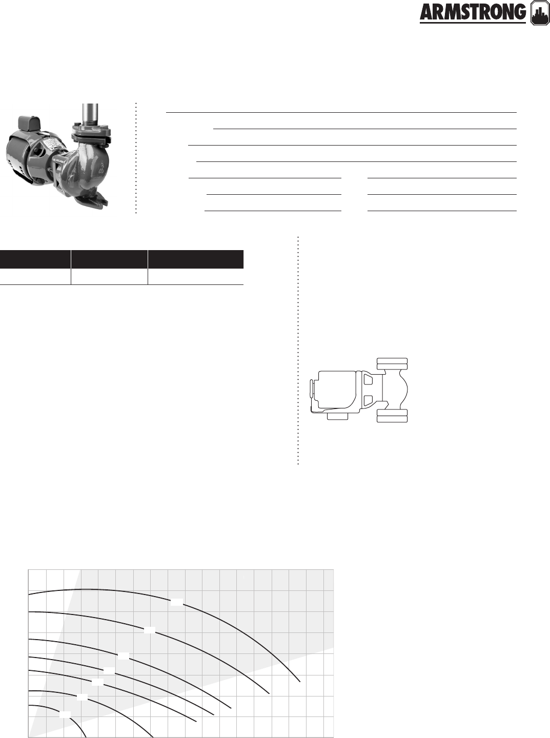
materials of construction
mechanical seal design data
ma ximum pump oper ating cond itions
150 psig at 275°f (1034 kPa at 135°c)
706
702
705
704
40
20
0
80
60
100
12.2
6.1
0
24.4
18.3
30.5
water, spgr = 1.0000
010203050607040 80 90 100 110 120
037.9 75.7 113.6 189.3 227.1 265.0151.4 302.8 340.7 378.5 416.4 454.2
710
709
707
1.25x1x5 @ 3600 rpm
1.5x1.25x5.5 @ 3600 rpm
2x1.5x5.5 @ 3600 rpm
1
1
2
3
2
3
1
flow - usgpm
flow - l/s
head - feet
head - metres
performance curve
Mount the pump on a foundation suciently
substantial to absorb any vibration. A good
foundation should weigh approximately two-and
one-half times the shipping weight of the pump.
mounting orientation
motor design data
optional equipment
Construction: Bronze Fitted
Impeller: Ultem
Casing/Volute: Cast iron
O-ring: Viton
Adapter: Aluminum
Shaft: 416 Stainless steel
Seal type: 21
Insert : Carbon
Seal: Ceramic
Bellows: Viton
L-cup: Viton
Retainer: Stainless steel
Spring: Stainless steel
kW:
Enclosure : 50j
rpm: 3500
Hertz: 60 Hz
Eciency: Standard
o Flush line for vertical mounting
back to
contents
<
4270 PUMPS
MOTOR MOUNTED
|
SUBMITTAL
40
|
HYDRONIC SOLUTIONS CATALOG
model suction discharge impeller
size
motor dimensions inches (mm) weight
hp a b c l* t w x y lbs (kg)
702** 1.25 (31) 1.00 (25) 3.50 (88) ¾
2.90
(73)
4.80
(121)
3.80
(95)
8.80
(222)
3.10
(79)
8.30
(210)
4.20
(106)
4.80
(121)
38 (84)
704** 1.25 (31) 1.00 (25) 4.00 (100) 140 (88)
705** 1.25 (31) 1.00 (25) 4.50 (114) 1½ 49 (108)
706** 1.50 (38) 1.25 (31) 4.50 (114) 251 (113)
707** 2.00 (50) 1.50 (38) 4.00 (100) 1½
2.90
(73)
4.80
(121)
3.80
(95)
8.80
(222)
3.10
(79)
8.50
(216)
4.20
(106)
4.80
(121)
53 (117)
709T2.00 (50) 1.50 (38) 4.38 (111) 256 (124)
710T2.00 (50) 1.50 (38) 5.00 (125) 3 60 (132)
model bronze fitted all bronze
702S410133-201 410133-241
702T410133-301 410133-341
704S410133-203 410133-243
704T410133-303 410133-343
705S410133-204 410133-244
705T410133-304 410133-344
706S410134-200 410134-240
706T410134-300 410134-340
707S410135-200 410135-240
707T410135-300 410135-340
709T410135-302 410135-342
710T410135-303 410135-343
part numbers
dimension data - inches (mm)
All dimensions are in inches (mm) and weights in lbs (kg)
*Motors are available with open drip-proof enclosures only.
**Add sux to the end of the model number.
Sux number: s: for 60 hz - 1 phase - 115 v / 230 v (230 v
only for 3 hp and 5 hp)
t: for 60 hz - 3 phase - 208-230 v / 460v
w
y
x
t
std ¼"npt drain
plug at 3
location
¼" npt
suction
vent
b
c
a
l
discharge
W × 1" slot
W × 1½" slot
5½"
3Y"
3Y"
7"
4360 PUMP-IN-A-BOX
CLOSE-COUPLED VIL PUMPS
|
SUBMITTAL
41
|
HYDRONIC SOLUTIONS CATALOG
Job:
Representative:
Engineer:
Contractor:
Order no: Date:
Submitted by: Date:
Approved by: Date:
style inside single spring
Type Armseal (4360b)
Armstrong 2a (4360d)
Rotating face Carbon
Stationary face Ceramic (4360b)
Silicon-carbide (4360d)
Secondary seal buna-n (4360b)
epdm* (4360d)
Springs Stainless steel
Rotating hardware Stainless steel
* Not suitable for use on oil service
mechanical seal design data
100
0.5 1.0 1.5 2.0 3.05.0 7.010.0
80
60
50
40
30
20
10
5
10 20 30 40 50 60 80 100 200
2
3
6
9
15
20
30
7
04b
08d
08f
10d
06d
06b
12b
04f
02b
02d
flow - usgpm
flow - L/s
head- feet
head- metres
performance curve
technical data
Maximum working pressure: 175 psi (12 bar)
Maximum working temperature: 225°f (107°c )
npt end connections (companion flanges included)
materials of construction
Casing: Cast iron Motor shaft: Carbon steel
Companion flanges: Cast iron Stub shaft (4360 b): Stainless steel
Motor/pump bracket: Cast iron Shaft sleeve (4360 d): Bronze
Impeller: Bronze
motor design data
Frequency: 60 hz Voltage: See below Enclosure: odp (4360b)
Eciency: std (4360b)
Energy ecient nema 12.11 (4360d)
tefc (4360d)
back to
contents
<
4360 PUMP-IN-A-BOX
CLOSE-COUPLED VIL PUMPS
|
SUBMITTAL
42
|
HYDRONIC SOLUTIONS CATALOG
motor data - inches (mm)
dimension data - inches (mm)
Note:
a. For exact installation data please write factory for certified dimensions.
b. All motors are 3-phase 1800 rpm except:
1 3600 rpm
2 1-phase
h
d
y
x
performance
curve model part number inlet & outlet
(npt) hp
208-230/460 volts 575 volts
02b 4360b-1205t-1.5/2 4360b00ah-083 4360b00ah-068 1.25"µ1.25" 11.5
02d 4360b-1205t-2.0/2 4360b00aj-083 4360b00aj-068 1.25"µ1.25" 12
04b 4360b-1505t-0.5/4 4360b00bc-062 (115/230v only) 1.5"µ1.5" 20.5
04f 4360b-1505t-3.0/2 4360b00bm-083 4360b00bm-083 1.5"µ1.5" 13
06b 4360b-2205t-0.5/4 4360b00cc-062 (115/230v only) 2"µ2" 20.5
06d 4360b-2205t-0.7/4 4360b00cd-068 4360b00cd-083 2"µ2" 0.75
08d 4360d-1507t-1.0/4 4360d00ag-083 4360d00ag-068 1.5"µ1.5" 1
08f 4360d-1507t-1.5/4 4360d00ai-083 4360d00ai-068 1.5"µ1.5" 1.5
10d 4360d-2207t-2.0/4 4360d-2207t-2.0/4 4360d00bl-068 2"µ2" 2
12b 4360d-3307t-1.5/4 4360d00ci-083 4360d00ci-068 3"µ3" 1.5
model dimensions - inches (mm) weight
lbs (kg)
x y h d
4360b-1205t-1.5/2 11.50 (292) 8.75 (222) 12.75 (324) 3.56 (90) 42 (19.0)
4360b-1205t-2.0/2 11.50 (292) 8.75 (222) 13.13 (334) 3.56 (90) 47 (21.3)
4360b-1505t-0.5/4 11.63 (295) 8.75 (222) 12.75 (324) 3.56 (90) 43 (19.5)
4360b-1505t-3.0/2 11.63 (295) 8.75 (222) 13.13 (334) 5.20 (132) 58 (26.3)
4360b-2205t-0.5/4 11.75 (298) 8.88 (226) 12.75 (324) 3.50 (89) 49 (22.2)
4360b-2205t-0.7/4 11.75 (298) 8.88 (226) 12.75 (324) 3.50 (89) 51 (23.1)
4360d-1507t-1.0/4 13.50 (343) 10.75 (273) 13.75 (349) 3.25 (83) 110 (49.9)
4360d-1507t-1.5/4 13.50 (343) 10.75 (273) 14.75 (375) 3.25 (83) 115 (52.2)
4360d-2207t-2.0/4 14.00 (356) 11.13 (283) 14.75 (375) 3.50 (89) 120 (54.4)
4360d-3307t-1.5/4 18.00 (457) 13.13 (334) 14.81 (376) 4.50 (114) 130 (59.0)
4360 PUMP-IN-A-BOX
CLOSE-COUPLED VIL PUMPS
|
SUBMITTAL
43
|
HYDRONIC SOLUTIONS CATALOG
installation
hanger supported pipe mounted motor lifting hook supported mounted on rigid base without
flexible connectors
44
|
HYDRONIC SOLUTIONS CATALOG
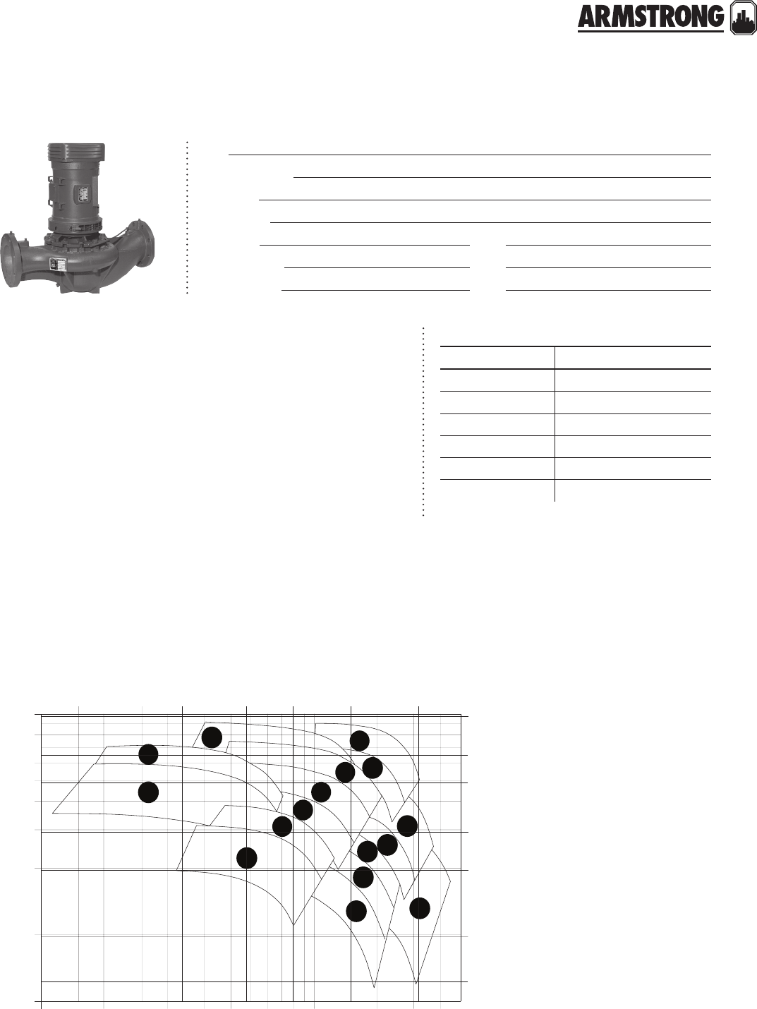
4380 PUMP-IN-A-BOX
CLOSE-COUPLED VIL PUMPS
|
SUBMITTAL
45
|
HYDRONIC SOLUTIONS CATALOG
Job:
Representative:
Engineer:
Contractor:
Order no: Date:
Submitted by: Date:
Approved by: Date:
style inside single spring
Type Armstrong 2a
Rotating face Carbon
Stationary face Silicon-carbide
Secondary seal epdm*
Springs Stainless steel
Rotating hardware Stainless steel
* Not suitable for use on oil service
mechanical seal design data
530402010 60 80 100200 300400
14f
14d
20d 26d
24d
24b
22f
22d
22b 28f
18d
18b
16d
18f 26b
16b
flow - usgpm
flow - L/s
head- feet
head- metres
100
80
60
50
40
30
20
10
5
2
3
6
9
15
20
30
0.5 1.0 1.5 2.0 3.0 5.0 10.0 20.0
performance curve
technical data
Maximum working pressure: 175 psi (12 bar)
Maximum working temperature: 250°f (121°c )
Flange rating: ansi 125
materials of construction
Casing: Cast iron Motor shaft: Carbon steel
Companion flanges: Cast iron Shaft sleeve: Bronze
Impeller: Bronze Gasket: Non-asbestos fiber
motor design data
Frequency: 60 hz Phase & voltage: 3 phase 208-230/460 v or 575 v
Enclosure: tefc Eciency: Energy ecient nema 12.11
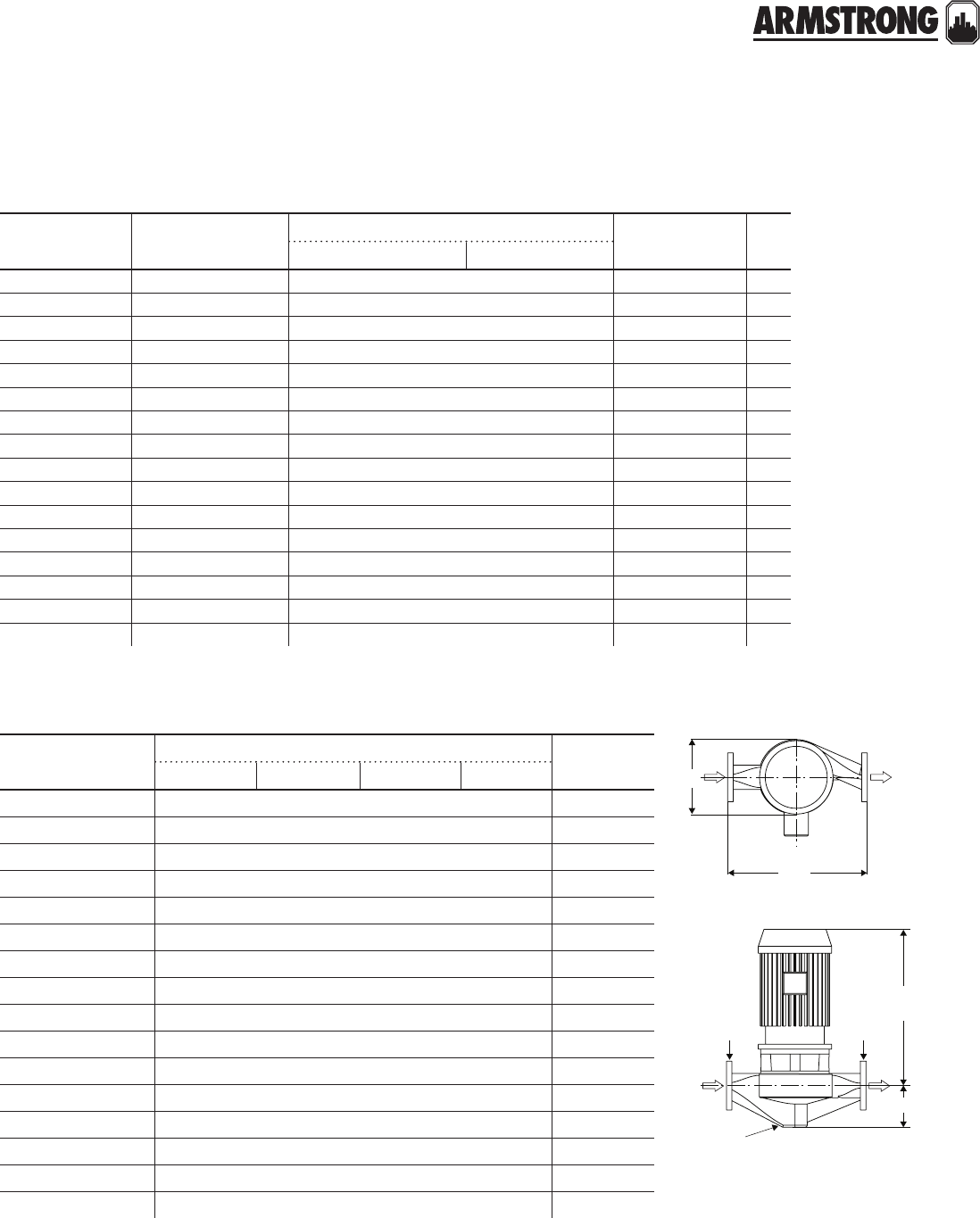
4380 PUMP-IN-A-BOX
CLOSE-COUPLED VIL PUMPS
|
SUBMITTAL
46
|
HYDRONIC SOLUTIONS CATALOG
motor data - inches (mm)
dimension data - inches (mm)
For exact installation data please write factory for certified dimensions.
h
y
x
d
1
2
2
1
1¼" npt gauge tappings
¼" npt drain
model dimensions - inches (mm) weight
lbs (kg)
x y h d
4380-1508f-1.5/4 16.00 (406) 11.75 (298) 15.75 (400) 5.75 (146) 156 (70.8)
4380-1508f-2.0/4 16.00 (406) 11.75 (298) 15.75 (400) 5.75 (146) 156 (70.8)
4380-2206f-1.0/4 15.00 (381) 10.63 (270) 14.75 (375) 4.88 (124) 140 (63.5)
4380-2206f-1.5/4 15.00 (381) 10.63 (270) 15.75 (400) 4.88 (124) 145 (65.8)
4380-2208f-2.0/4 18.00 (457) 11.75 (298) 15.75 (400) 5.13 (130) 172 (78.0)
4380-2208f-3.0/4 18.00 (457) 12.75 (324) 20.13 (511) 5.13 (130) 187 (84.8)
4380-2208f-5.0/4 18.00 (457) 12.75 (324) 20.13 (511) 5.13 (130) 212 (96.2)
4380-2210f-5.0/4 19.00 (483) 13.75 (349) 20.13 (511) 5.38 (137) 245 (111.1)
4380-3306f-1.0/4 18.00 (457) 11.88 (302) 14.75 (375) 6.00 (152) 156 (70.8)
4380-3306f-1.5/4 18.00 (457) 11.88 (302) 6.00 (152) 6.00 (152) 161 (73.0)
4380-3306f-2.0/4 18.00 (457) 11.88 (302) 15.75 (400) 6.00 (152) 161 (73.0)
4380-3308f-3.0/4 22.00 (559) 13.88 (253) 20.13 (511) 6.38 (162) 213 (96.6)
4380-3308f-5.0/4 22.00 (559) 13.88 (253) 20.13 (511) 6.38 (162) 238 (108.0)
4380-3310f-5.0/4 21.00 (533) 14.25 (362) 20.13 (511) 6.25 (159) 282 (128.0)
4380-3310f-7.5/4 21.00 (533) 16.63 (422) 25.63 (651) 6.25 (159) 331 (150.1)
4380-4406f-3.0/4 22.00 (559) 13.88 (353) 20.38 (518) 7.75 (197) 213 (96.6)
performance
curve model part number inlet & outlet
(ansi 125) hp
208-230/460 volts 575 volts
14d 4380-1508f-1.5/4 4380008ai-083 4380008ai-068 1.5"µ1.5" 1.5
14f 4380-1508f-2.0/4 4380008al-083 4380008al-068 1.5"µ1.5" 2
16b 4380-2206f-1.0/4 4380006bg-083 4380006bg-068 2"µ2" 1
16d 4380-2206f-1.5/4 4380006bi-083 4380006bi-068 2"µ2" 1.5
18b 4380-2208f-2.0/4 4380008bl-083 4380008bl-068 2"µ2" 2
18d 4380-2208f-3.0/4 4380008bo-083 4380008bo-068 2"µ2" 3
18f 4380-2208f-5.0/4 4380008br-083 4380008br-068 2"µ2" 5
20d 4380-2210f-5.0/4 4380010ar-083 4380010ar-068 2"µ2" 5
22b 4380-3306f-1.0/4 4380006cg-083 4380006cg-068 3"µ3" 1
22d 4380-3306f-1.5/4 4380006ci-083 4380006ci-068 3"µ3" 1.5
22f 4380-3306f-2.0/4 4380006cl-083 4380006cl-068 3"µ3" 2
24b 4380-3308f-3.0/4 4380008co-083 4380008co-068 3"µ3" 3
24d 4380-3308f-5.0/4 4380008cr-083 4380008cr-068 3"µ3" 5
26b 4380-3310f-5.0/4 4380010br-083 4380010br-068 3"µ3" 5
26d 4380-3310f-7.5/4 4380010bv-083 4380010bv-068 3"µ3" 7.5
28f 4380-4406f-3.0/4 4380006do-083 4380006do-068 4"µ4" 3

4380 PUMP-IN-A-BOX
CLOSE-COUPLED VIL PUMPS
|
SUBMITTAL
47
|
HYDRONIC SOLUTIONS CATALOG
installation
hanger supported pipe mounted motor lifting hook supported mounted on rigid base without
flexible connectors
48
|
HYDRONIC SOLUTIONS CATALOG
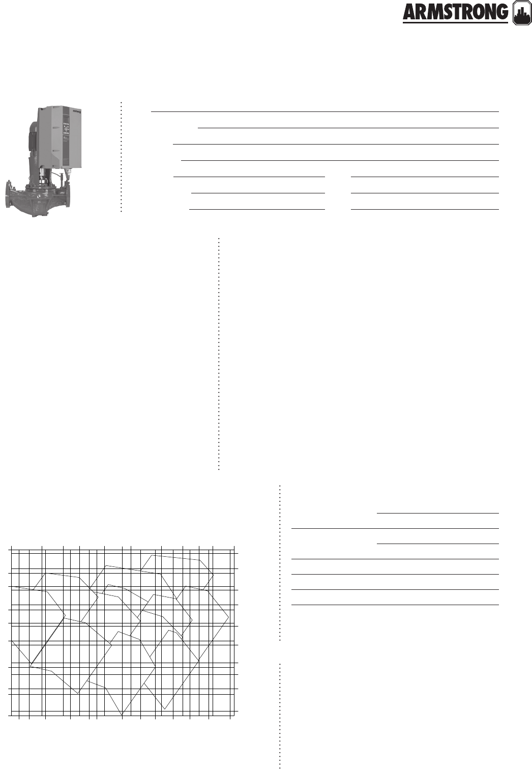
DESIGN ENVELOPE 4300/4380 PUMP-IN-A-BOX
VERTICAL IN-LINE PUMPS
|
SUBMITTAL
49
|
HYDRONIC SOLUTIONS CATALOG
Job:
Representative:
Engineer:
Contractor:
Order no: Date:
Submitted by: Date:
Approved by: Date:
mechanical seal design data
35
6
9
10
15
25
35
45
70
90
140
2
3
4
5
7
10
15
20
30
40
40 50 70 90 100 140 180 220 280 350 450 600
2 3 4 5 7 9 10 15 20 25 4030
flow - usgpm
flow - L/s
head- feet
head- metres
Design Envelope
4380 PiB
1 1506-003.0
2 1508-001.5
3 0206-001.5
4 0208-003.0
5 0208-005.0
6 0306-001.5
7 0308-003.0
8 0308-005.0
9 0310-007.5
1 0406-003.0
Design Envelope
4300 PiB
1 0308-015.0
1 0406-010.0
3
1
4
5
1
28
9
1
1
6
7
performance curve
technical data
Maximum working pressure: 175 psi (12 bar)
Maximum working temperature: 250°f (121°c )
materials of construction
Construction: bf with ansi 125 flanged connection
Casing (volute): Cast iron (a48-30)
Casing gasket: Confined Non-Asbestos Fiber
Flush line: Braided Stainless Steel
Impeller: Bronze
Shaft sleeve (4380): Bronze
Pump shaft (4300): ss astm a276 Type 416
drive data
Sensorless control: Included
bms protocol: BACnet ms/tp
Enclosure: ul type 12
Fused disconnect switch: No
Control orientation: l1
Communication port: rs 485
emi/rfi control: Integrated filter designed to meet en61800-3
Harmonic suppression: Integrated dc link reactors**
Cooling: Fan-cooled through back channel
Ambient temperature: -10°c to +45°c upto 1000 meters
elevation (14°f to 113°f upto 3280ft)
Analog inputs: Two, current or voltage
Analog outputs: One, current
Digital inputs: Four programmable
Digital outputs: Two programmable
motor design data
Frequency: 60 hz Voltage: 208-230
460 v 575 v
Enclosure: tefc
Eciency: nema premium 12.12
Seal type: Inside single-spring (4380)
Outside balanced (4300)
Secondary seal: epdm (4380)
viton (4300)
Rotating face: Resin bonded carbon
Stationary seat: Silicon-carbide
Springs: Stainless steel
Rotating hardware: Stainless steel
• Pump equipped with casing drain plug and ¼" npt suction and
discharge gauge ports
* If minimum maintained system pressure is not known, default is
40% of design head.
** The ivs 102 control is a low harmonic control with a built-in dc link
reactor equivalent in performance to a 5% ac line reactor. This does
not guarantee performance to any system wide harmonic specifi-
cation or the costs to meet a system wide specification. If supplied
with the system electrical details, Armstrong will run a computer
simulation of the system wide harmonics. If system harmonic
levels are exceeded, Armstrong can also recommend additional
harmonic mitigation and the cost for such mitigation.
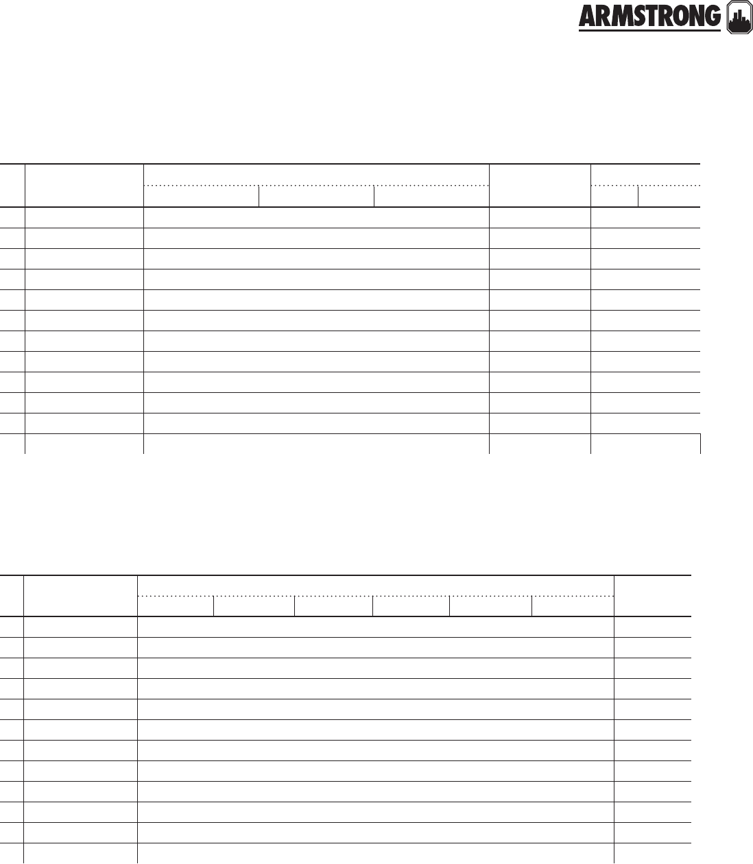
DESIGN ENVELOPE 4300/4380 PUMP-IN-A-BOX
VERTICAL IN-LINE PUMPS
|
SUBMITTAL
50
|
HYDRONIC SOLUTIONS CATALOG
motor data - inches (mm)
dimension data - inches (mm)
For exact installation data please write factory for certified dimensions.
model dimensions - inches (mm) weight
lbs (kg)
b e f t sd x
14380 1506-003.0 3.86 (98) 11.87 (301) 18.85 (479) 4.25 (108) 14.25 (362) 21.32 (542) 202 (91.6)
24380 1508-001.5 5.72 (145) 11.85 (301) 19.85 (504) 4.59 (117) 16.00 (406) 21.36 (543) 198 (89.8)
34380 0206-001.5 4.47 (114) 11.87 (301) 19.85 (504) 4.59 (117) 15.00 (381) 21.35 (542) 187 (84.8)
44380 0208-003.0 5.72 (145) 12.56 (319) 22.06 (560) 5.09 (129) 18.00 (457) 21.86 (555) 239 (108.4)
54380 0208-005.0 5.72 (145) 12.56 (319) 22.06 (560) 5.09 (129) 18.00 (457) 21.86 (555) 244 (110.7)
64380 0306-001.5 5.80 (147) 11.85 (301) 21.60 (549) 6.00 (152) 18.00 (457) 24.92 (633) 203 (92.1)
74380 0308-003.0 6.81 (173) 12.56 (319) 24.56 (624) 6.31 (160) 22.00 (559) 21.86 (555) 265 (120.2)
84380 0308-005.0 6.81 (173) 12.56 (319) 24.56 (624) 6.31 (160) 22.00 (559) 21.86 (555) 270 (122.5)
94380 0310-007.5 7.16 (182) 12.55 (319) 27.77 (705) 5.44 (138) 21.00 (533) 28.83 (732) 368 (166.9)
1 4380 0406-003.0 6.88 (175) 12.00 (305) 24.00 (610) 8.00 (203) 22.00 (559) 26.67 (758) 265 (120.2)
1 4300 0308-015.0 6.88 (175) 13.17 (335) 13.17 (335) 7.75 (197) 22.00 (559) 29.41 (747) 431 (195.5)
1 4300 0406-010.0 6.88 (175) 14.82 (376) 14.82 (376) 7.75 (197) 22.00 (559) 31.99 (812) 331 (150.1)
design envelope
model
part number inlet & outlet
ansi 125
motor details
208-230 volts 460 volts 575 volts hp* frame
14380 1506-003.0 20212uegbnsxxxxx 20214uegbnsxxxxx 20215uegbnsxxxxx 1.5"µ1.5" 13182
24380 1508-001.5 22412uegbnsxxxxx 22414uegbnsxxxxx 22415uegbnsxxxxx 1.5"µ1.5" 1.5 145
34380 0206-001.5 21012uegbnsxxxxx 21014uegbnsxxxxx 21015uegbnsxxxxx 2"µ2" 1.5 145
44380 0208-003.0 22812uegbnsxxxxx 22814uegbnsxxxxx 22815uegbnsxxxxx 2"µ2" 3182
54380 0208-005.0 22912uegbnsxxxxx 22914uegbnsxxxxx 22915uegbnsxxxxx 2"µ2" 5184
64380 0306-001.5 21412uegbnsxxxxx 21414uegbnsxxxxx 21415uegbnsxxxxx 3"µ3" 1.5 145
74380 0308-003.0 23212uegbnsxxxxx 23214uegbnsxxxxx 23215uegbnsxxxxx 3"µ3" 3182
84380 0308-005.0 23312uegbnsxxxxx 23314uegbnsxxxxx 23315uegbnsxxxxx 3"µ3" 5184
94380 0310-007.5 24512uegbnsxxxxx 24514uegbnsxxxxx 24515uegbnsxxxxx 3"µ3" 7. 5 213
1 4380 0406-003.0 21912uegbnsxxxxx 21914uegbnsxxxxx 21915uegbnsxxxxx 4"µ4" 3182
1 4300 0308-015.0 04212uegbnsxxxxx 04214uegbnsxxxxx 04215uegbnsxxxxx 3"µ3" 115 213-5TC
1 4300 0406-010.0 51712uegbnsxxxxx 51714uegbnsxxxxx 51715uegbnsxxxxx 4"µ4" 110 213-5TC
*All motors are with nema premium 12.12 eciency and tefc enclosure.
Note: All motors are three-phase, four-pole except: 1 Two-pole
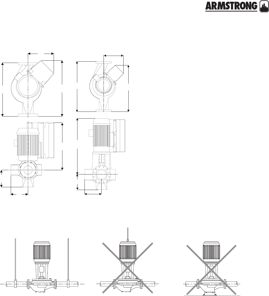
DESIGN ENVELOPE 4300/4380 PUMP-IN-A-BOX
VERTICAL IN-LINE PUMPS
|
SUBMITTAL
51
|
HYDRONIC SOLUTIONS CATALOG
installation
hanger supported pipe mounted motor lifting hook supported mounted on rigid base without
flexible connectors
f
e
b
t
x
sd
f
e
t
x
b
sd
de 4380 de 4300
52
|
HYDRONIC SOLUTIONS CATALOG
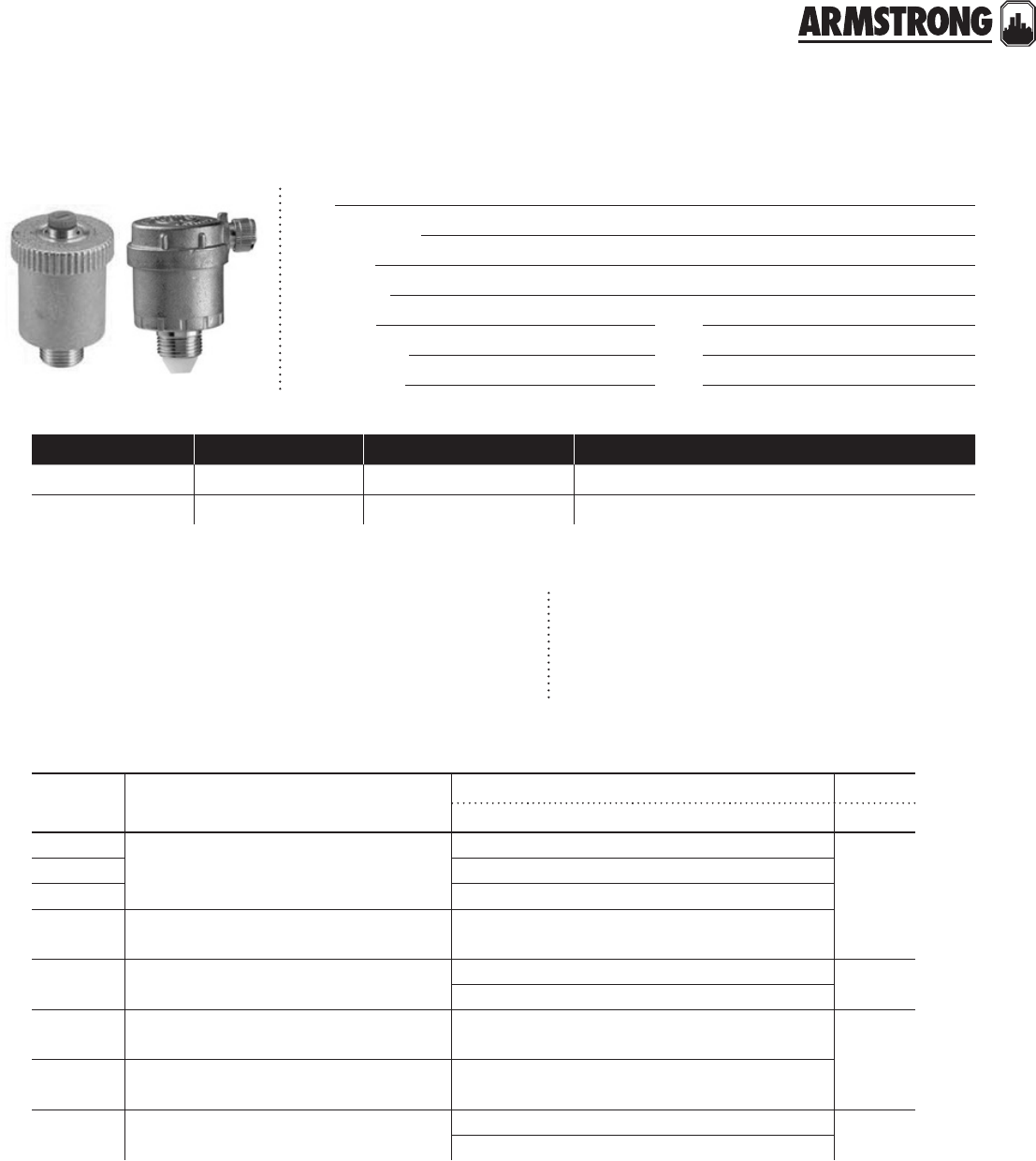
AUTOMATIC AIR VENTS
HYDRONIC SPECIALTIES
|
SUBMITTAL
53
|
HYDRONIC SOLUTIONS CATALOG
Job:
Representative:
Engineer:
Contractor:
Order no: Date:
Submitted by: Date:
Approved by: Date:
materials of construction technical data
Body and cover: Brass Fitted
Internal components: Non-Ferrous
quantity tag no. model no. comments
Maximum working pressure: 150 psi (1034 kPa)
Maximum working temperature: 248°f (120°c)
Minimum working temperature: 15°f (-10°c)
dimension data - inches (mm)
model description dimensions inches (mm) weight
a b c d lbs (oz.)
ava-013 Automatic Air Vent
with angled discharge
V" npt 2.06 (52) 1.88 (48) 2.25 (57)
0.20
(0.10)
ava-025 N" npt 2.06 (52) 1.88 (48) 2.25 (57)
ava-038 W" npt 2.06 (52) 1.88 (48) 2.25 (57)
ava-050 Automatic Air Vent with angled discharge
and service check valve K" npt 2.25 (57) 1.88 (48) 3.19 (81)
ava-075 Automatic Air Vent with angled discharge
and m/f adapter
O" mpt 3.25 (83) 1.88 (48) -0.50
(0.28)
K" fpt 3.25 (83) 1.88 (48) -
avv-038 High capacity Automatic Air Vent with
vertical discharge W" npt 2.94 (75) 1.88 (48) 3.25 (83) 0.35
(0.16)
avv-050 High capacity Automatic Air Vent with
vertical discharge and service check valve K" npt 3.25 (83) 1.88 (48) 4.19 (106)
avv-075 High capacity Automatic Air Vent with
vertical discharge and m/f adapter
O" mpt 4.00 (100) 1.88 (48) -0.60
(0.22)
K" fpt 4.00 (100) 1.88 (48) -
back to
contents
<
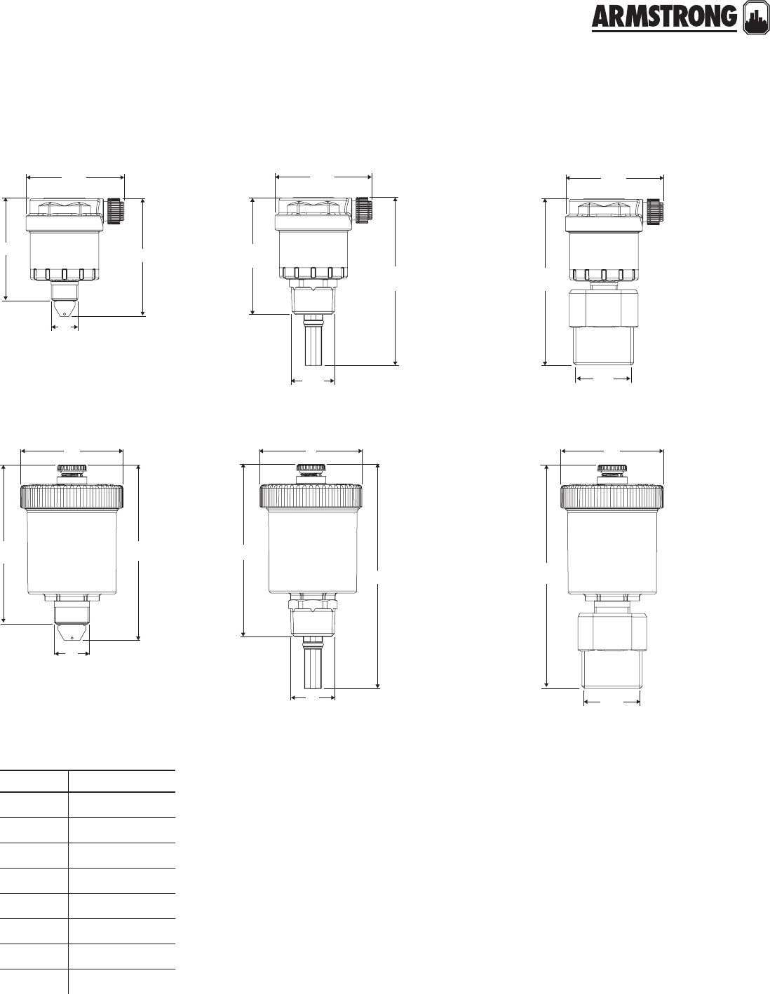
AUTOMATIC AIR VENTS
HYDRONIC SPECIALTIES
|
SUBMITTAL
54
|
HYDRONIC SOLUTIONS CATALOG
c
d
b
a
d
a
b
c
c
b
a
c
d
a
b
c
d
a
b
c
b
a
Models ava-013, -025 & -038
Models avv-038
Models ava-075
Models avv-075
Models ava-050 with service check valve
Models avv-050 with service check valve
model part number
ava-013 272005-300
ava-025 272005-301
ava-038 272005-302
ava-050 272005-303
ava-075 272005-308
avv-038 272005-305
avv-050 272005-306
avv-075 272005-307
part numbers
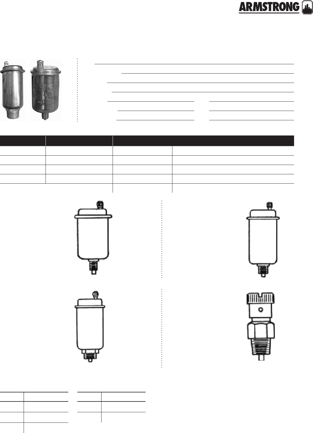
FLOAT TYPE AIR VENTS
HYDRONIC SPECIALTIES
|
SUBMITTAL
55
|
HYDRONIC SOLUTIONS CATALOG
Job:
Representative:
Engineer:
Contractor:
Order no: Date:
Submitted by: Date:
Approved by: Date:
model number pipe size quantity required identification
67 V"(3.18)m
71 ¼"(6.35)m
72 V"(3.18)m
75 ½"(12.7)f & O"(19.05)m
7a overflow connector
no. 67 auto-vent
Vertical mounting V" i.p.
Male connection.
Up to 35 lbs. pressure
3¾ × 1I/af"
no. 75 auto-vent
Combination connection-
½" npt Female and
O" npt Male
Up to 150 lbs. pressure
no. 71 auto-vent
Vertical mounting N" npt.
Male connection.
Up to 150 lbs. pressure
4W × 2N"
no. 72 auto-vent
Vertical or horizontal
mounting V"npt
Male connection
Up to 75 lbs. pressure
1N × K"
note: All dimensions are in inches (mm)
model part number
67 272005-004
71 272005-002
72 272005-005
model part number
75 272005-003
7a 272005-006
part numbers
56
|
HYDRONIC SOLUTIONS CATALOG
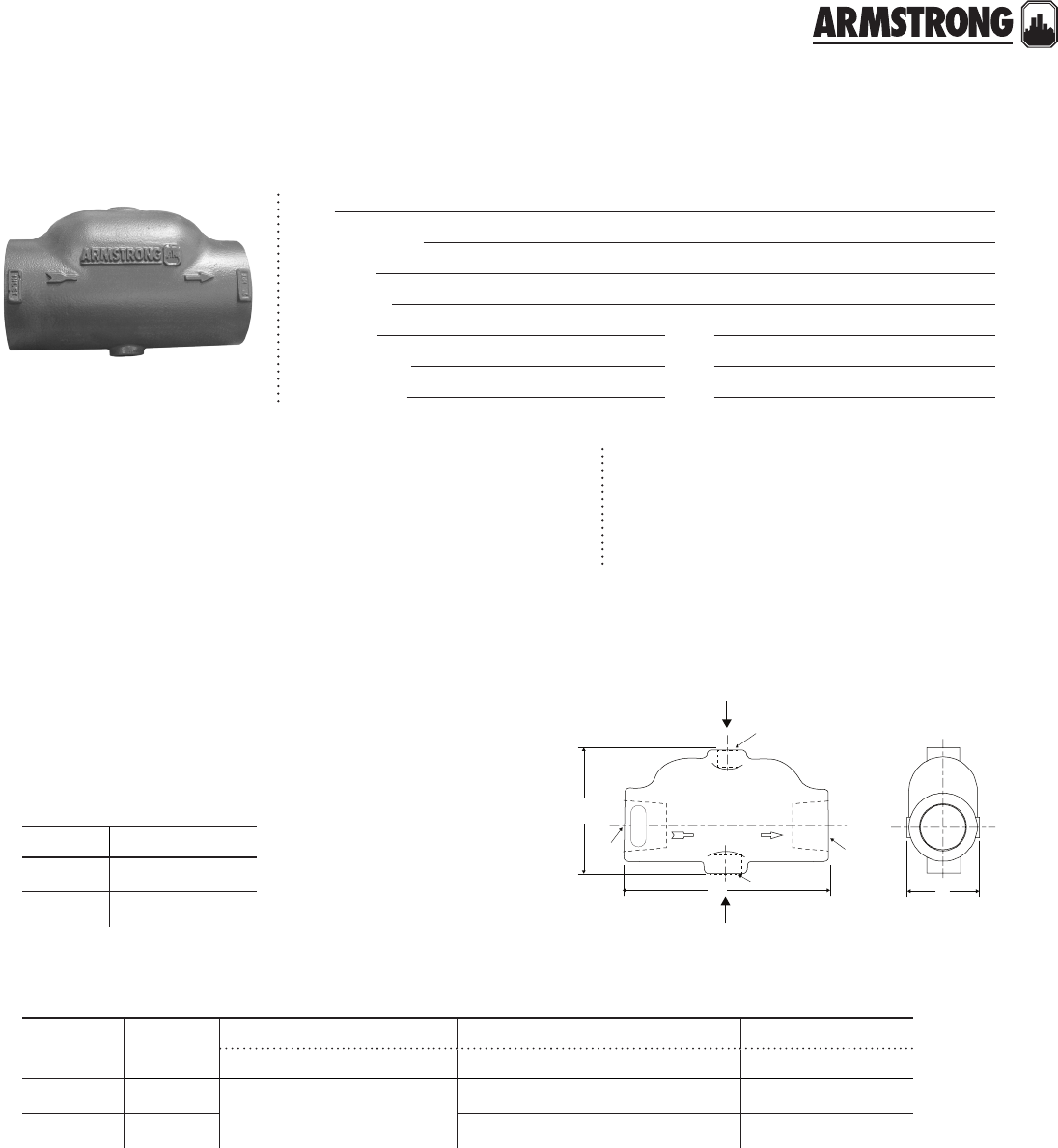
AIR REMOVAL TRAP
HYDRONIC SPECIALTIES
|
SUBMITTAL
57
|
HYDRONIC SOLUTIONS CATALOG
Job:
Representative:
Engineer:
Contractor:
Order no: Date:
Submitted by: Date:
Approved by: Date:
model part number
art-447 572017-005
art-448 572017-006
part numbers
mounting orientation
design features
One piece heavy cast iron construction
Suitable for pipe-line mounting
Units painted gray enamel
Arrow indicates direction of flow
Use #67 auto air vent at top of 1"(25.4 mm) - 1.5" (38.1 mm) purgers
Use #75 auto air vent at top on 2" (50.8 mm) - 3" (76.2 mm)
ma ximum pump oper ating cond itions
125 psig at 225°f (1207 kPa at 107°c)
Install the unit ensuring the flow direction will
match the arrow on the casing and the air vent
connection is on top.
horizontal mounted air separator having
in-line inlet & outlet designed for separation
of air in hydronic systems.
inlet
vent
v
connect to airvent
connect to expansion tank
u
u
b
azc
model no pipe size dimensions inches (mm) tappings- n.p.t. shipping weight
a b c u (n.p.t.) v (n.p.t.) z (n.p.t.) lbs (kg)
art-447 2.50 (63) 10.0 0
(254)
6.0 0
(152)
5.00
(127)
2.5 (63) 0.75 (19) 0.5 (13) 19 (8.62)
art-448 3.00 (76) 3.00 (76) 0.75 (19) 0.5 (13) 20 (9.07)
dimension data - inches (mm)
All dimensions are in inches (mm) and weights in lbs (kg)
Dimensions shown are for reference only
back to
contents
<
58
|
HYDRONIC SOLUTIONS CATALOG
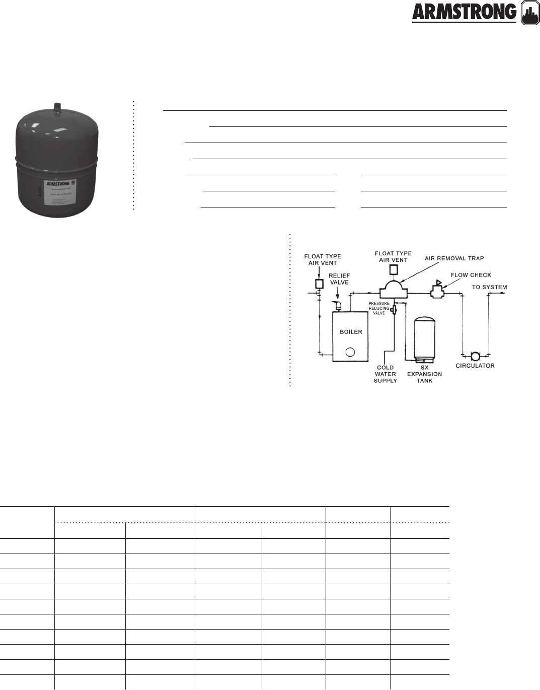
DIAPHRAGM EXPANSION TANK
HYDRONIC SPECIALTIES
|
SUBMITTAL
59
|
HYDRONIC SOLUTIONS CATALOG
Job:
Representative:
Engineer:
Contractor:
Order no: Date:
Submitted by: Date:
Approved by: Date:
design features
technical data
mounting orientation
Maximum working pressure: 100 psi (689 kPa)
Maximum working temperature: 240°f (116°c)
Standard factory pre-charge
(may be field adjusted): 12 psi (83 kPa)
dimension data - inches (mm)
tanks
model no.
size dimensions inches (mm) system weight
volume (gal.) accept (gal.) a b conn. (n.p.t) lbs (kg)
15 2 0.9 11.50 (292) 8.00 (203) 0.50 (13) 5 (2.27)
30 4.4 2.4 14.00 (356) 11.00 (279) 0.50 (13) 9 (4.08)
60 7.6 2.4 23.00 (584) 11.00 (279) 0.50(13) 14 (6.35)
90 14 11.3 21.00 (533) 15.00 (381) 0.50 (13) 23 (10.43)
sx-30v 14 11.3 24.00(610) 15.00 (381) 1.00 (25) 25 (11.34)
sx-40v 20 11.3 31.75 (806) 15.00 (381) 1.00 (25) 32 (14.51)
sx-60v 32 11.3 46.63 (1184) 15.00 (381) 1.00 (25) 45 (20.41)
sx-90v 45 34 36.00 (914) 22.00 (559) 1.25 (32) 70 (31.75)
sx-110v 62 34 46.50 (1181) 22.00 (559) 1.25 (32) 92 (41.73)
sx-160v 86 46 47.19 (1199) 26.00 (660) 1.25 (32) 113 (51.26)
Permanent air cushion
Mild steel shell
Enamel finish
Eliminates water logging
Diaphragm separates 12 psi air cushion from expanding system water
Saves space and installation costs
Multiple unit installation for larger volume capacity
All figures are nominal.
Do not use with fresh or potable water.
back to
contents
<
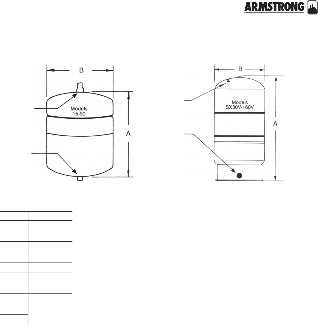
DIAPHRAGM EXPANSION TANK
HYDRONIC SPECIALTIES
|
SUBMITTAL
60
|
HYDRONIC SOLUTIONS CATALOG
model part number
15 572018-001
30 572018-002
60 572018-003
90 572018-004
sx-30v 572018-005
sx-40v 572018-006
sx-60v 572018-007
sx-90v 572018-008
sx-110v 572018-009
sx-160v 572018-010
part numbers
system
connection
charging
valve
system
c
onnection
charging
valve
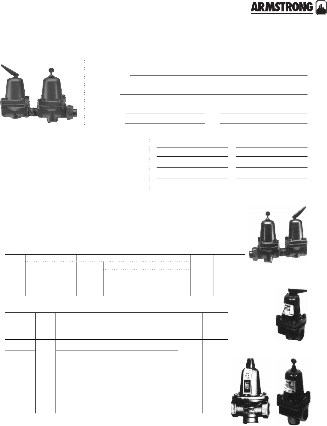
61
|
HYDRONIC SOLUTIONS CATALOG
RELIEF AND REDUCING VALVES
HYDRONIC SPECIALTIES
|
SUBMITTAL
Job:
Representative:
Engineer:
Contractor:
Order no: Date:
Submitted by: Date:
Approved by: Date:
combination relief and reducing valve
Bodies have built-in strainer, extra large diaphragms, ½" (12.7mm) sweat or threaded union
fitting and anti-siphon check valve feature on Reducing Valve. Reducing Valve is factory set
at 12 psi but is easily adjusted to meet varying building heights. The special composition
valve disc seat is brass and is practically noiseless during operation.
mounting orientation
The pressure reducing valve should be installed with
the flow arrow on the body pointing in the direction
of the flow.
model part number
C-11 216945-300
RL-11 216942-300
RD-11T/S 216944-300
model part number
RD-40 207937-343
RD-50 207937-300
HRD-70 207936-300
part numbers
model
size body construction
body
constr.
approx
ship.
weight
lbs (kg)
boiler fill relief
valve
reducing valve
factory setting
del. press.
readjustable
range
C-11 K (12.7) K (12.7) 30 (13.6) 12 (5.44) 7 to 25
(3.18 to 11.34) Brass 2.25 (1.02)
model size description body
constr.
approx
ship.
weight
lbs (kg)
RL-11 K
(12.7)
Max setting- 30 lbs (13.61 kg)
Brass
1.25
(0.57)
RD-11T/S reducing valves: All working parts are brass with
easily cleaned built-in strainer. Factory adjusted at 12 psi
suitable for buildings up to three stories high. Complete
with integral check valve, the RD-11 is equipped with
either a sweat or threaded tail piece on the inlet side.
RD-40
O
(19.0)
3.25
(1.47)
RD-50*
HRD-70 high pressure reducing valve: Factory adjusted for
150 lbs initial pressure, 45 lbs delivery pressure. Other
pressures must be specified when ordering. All working
parts (built in strainer and extra large diaphragm) are
brass. Complete with check valve.
All dimensions are in inches (mm) and weights in lbs (kg)
* The same unit is used in Armstrong Combination valve. RD-40
RD-50
HRD-70
RD-11
RL-11
C-11
back to
contents
<
62
|
HYDRONIC SOLUTIONS CATALOG
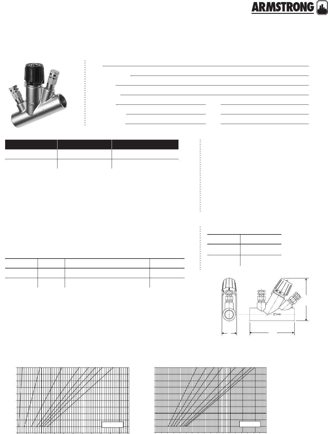
CIRCUIT BALANCING VALVES
MINI SWEAT
|
SUBMITTAL
63
|
HYDRONIC SOLUTIONS CATALOG
Job:
Representative:
Engineer:
Contractor:
Order no: Date:
Submitted by: Date:
Approved by: Date:
cbvs must be installed for flow in the
direction of the arrow on the valve body
and to allow easy access to the metering
ports and handwheel.
note: We recommend that the valve be
installed in such a way that the meter
connections be above or on the side of the
valve body. (Not below or at 6 o’clock).
mounting orientation
specification
Connection: Solder joint Material of construction : Brass
Handwheel: 1 turn 360°
ma ximum pump oper ating cond itions
300 psig at 250°f (2068 kPa at 121°c)
0.0 0.5 1.0 1.5 2.0 2.5 3.0 3.5 4.0 4.5 5.0 5.5 6.0
0.2 0.3 0.4 0.5 0.6 0.7 0.8 0.9
100
90
80
70
60
50
40
30
20
10
0
cbv - ½"ms
flow rate - USgpm
pressure drop - in. wg
handwheel position
0.0 0.5 1.0 1.5 2.0 2.5 3.0 3.5 4.0 4.5 5.0 5.5 6.0 6.5 7.0
flow rate - USgpm
pressure drop - in. wg
handwheel position
0.2 0.3 0.4 0.5 0.6 0.7 0.8 0.9
100
90
80
70
60
50
40
30
20
10
07.5 8.0 8.5 9.0
cbv - ¾"ms
performance curve
model no. quantity identification
c
a
b
model part number
CBV-K"MS 570109-332
CBV-O"MS 570109-333
part numbers
dimension data - inches (mm)
model pipe size a b c weight
CBV-K"MS K" 3.12 (79) 3.53 (90) 1.34 (34) 1.10 (0.50)
CBV-O"MS O"3.78 (96) 3.62 (92) 1.34 (34) 1.19 (0.54)
All dimensions are in inches (mm) and weights are in lbs (kg)
Solder style models are supplied unassembled. Valve body must be soldered in the line before assembly.
Refer to Cv curves for sizing and balancing, giving pressure drop at dierent settings and flow rates.
Suggested meters for use in conjunction with Armstrong cbvs are the cbdm-200, cbdm-135/60, dpm-15
and dpm-100.
All valves furnished with probe metering ports.
back to
contents
<
64
|
HYDRONIC SOLUTIONS CATALOG
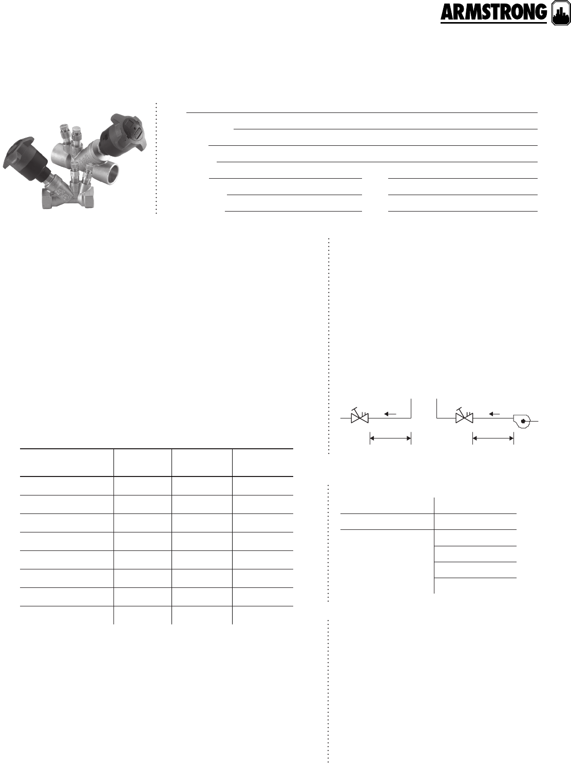
CIRCUIT BALANCING VALVES
VENTURI
|
SUBMITTAL
65
|
HYDRONIC SOLUTIONS CATALOG
Job:
Representative:
Engineer:
Contractor:
Order no: Date:
Submitted by: Date:
Approved by: Date:
ARMflo Circuit Balancing Valves are highly
resistant to turbulence induced by nearby piping
components and can often provide excellent
results when mounted directly to other fittings.
However, for optimum flow measurement
accuracy and when practical, locate the valve:
• 5 pipe diameters downstream of a fitting.
• 2 pipe diameters upstream of a fitting.
• 10 pipe diameters upstream or
downstream of a pump.
* Armstrong low flow circuit balancing valves are needed for systems where the
flow rate is below ashrae guidelines. Low flow units allow contractors to line
size the valve, despite the low flow velocity. In addition, low flow valves:
• Boost the dierential pressure signal to make the signal more stable
and reliable
• Provide superior flow regulation over the operating range
• Are less prone to blockage due to particles in the system fluid
• Accurately indicate a blockage condition
installation
technical data
Maximum working pressure: pn20 / 300 psi (2068 kPa)
Operating temperature range: -4°f to 300°f (-20°c to 150°c )
cbv cbv
5 d10 d
pump
model pipe size min.
flow rate
max.
flow rate
cbv050v(x)cr-lf* K" (dn15) 0.26 (0.02) 1.98 (0.12)
cbv075v(x)cr-lf* ¾" (dn20) 0.41 (0.03) 3.11 (0.20)
cbv050v(x)cr K" (dn15) 1.22 (0.08) 9.57 (0.60)
cbv075v(x)cr ¾" (dn20) 1.99 (0.13) 13.76 (0.87)
cbv100v(x)cr 1" (dn25) 5.36 (0.34) 19.90 (1.25)
cbv125v(x)cr 1¼" (dn32) 8.45 (0.53) 40.01 (2.52)
cbv150v(x)cr 1½" (dn40) 9.02 (0.57) 50.07 (3.15)
cbv200v(x)cr 2" (dn50) 15.50 (0.98) 81.92 (5.16)
flow rate ranges
materials of construction
accessories
notes
Body, bonnet: Brass alloy (forged) – cw602n
Corrosion resistant to reference en12165 per iso-6509
Stem and disc: Brass alloy (machined) – cw602n
Corrosion resistant to reference en12165 per iso-6509
Elastomers: epdm
Handwheel: Reinforced nylon; abs
pt ports
pt port extensions o 1O" o 2O"
Dierential pressure
manometers
cbdm 200
cbdm 135/60
dpm-15
dpm-100
Flow in USgpm(L/s)
Where model (x) = Connection Type: t = npt , s = Sweat, b = bspp (iso-228).
1 Solder style models - Valve body must be opened at
least one full turn prior to being soldered in the line.
2 For valve sizing, refer to the performance curve and
flow rate ranges. For balancing, use Venturi Cv curves
or slide rule, which display dierential pressure drop
across the Venturi for dierent flow rates.
3 Suggested dierential pressure meters for use with
Armstrong cbv’s are dpm-15 and dpm-100 digital
dierential pressure meters and cbdm 135/60 and
cbdm 200 analogue meters.
4 All valves furnished with probe metering ports.
back to
contents
<
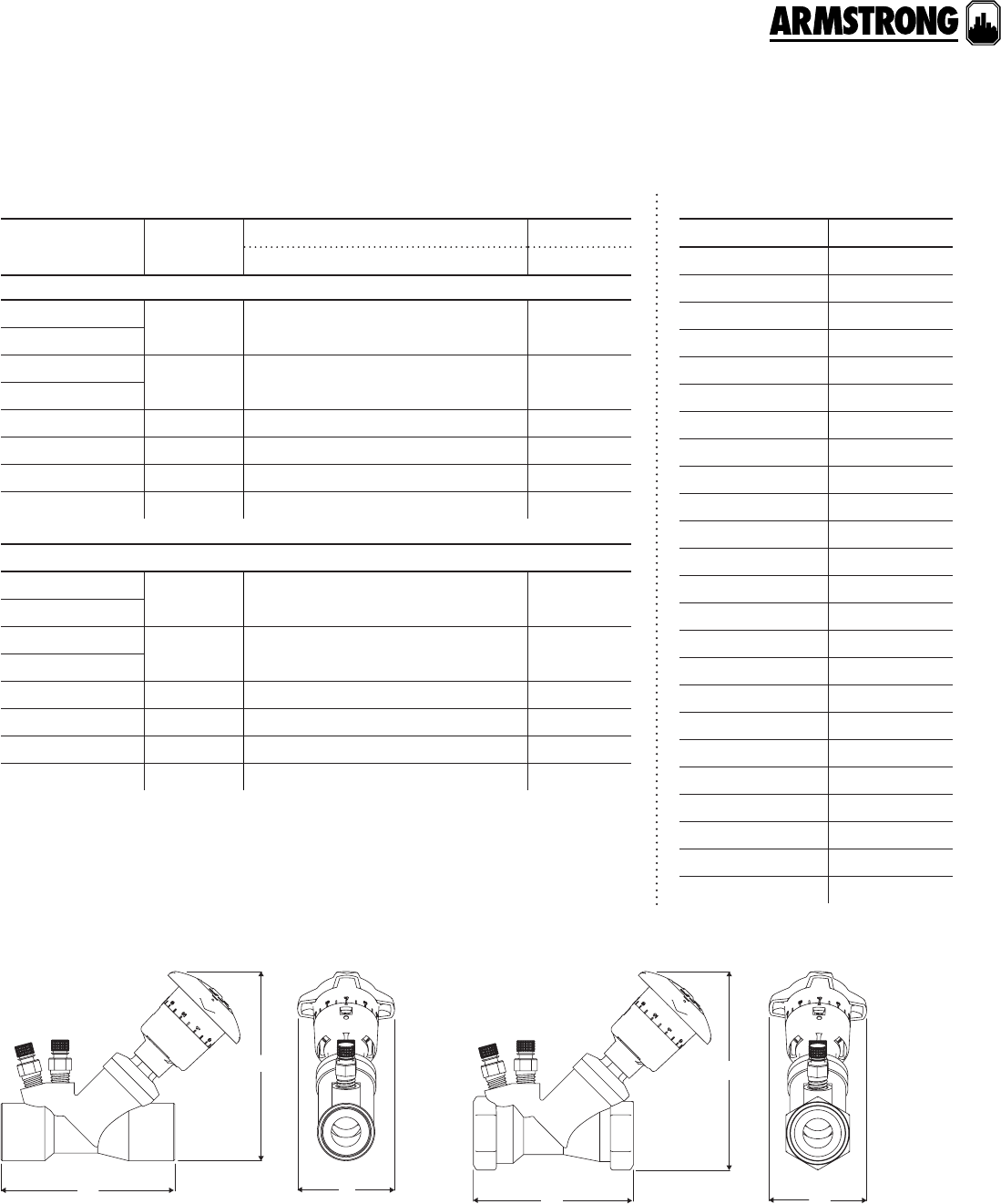
CIRCUIT BALANCING VALVES
VENTURI
|
SUBMITTAL
66
|
HYDRONIC SOLUTIONS CATALOG
dimension data - inches (mm)
model pipe size dimensions inches (mm) weight
a b c lbs (kg)
solder joint connection
cbv050vscr-lf K" (dn15) 3.19 (81) 4.56 (116) 2.76 (70) 1.05 (0.48)
cbv050vscr
cbv075vscr-lf ¾" (dn20) 3.64 (93) 4.65 (118) 2.76 (70) 1.09 (0.49)
cbv075vscr
cbv100vscr 1" (dn25) 4.26 (108) 4.95 (126) 2.76 (70) 1.68 (0.76)
cbv125vscr 1¼" (dn32) 4.94 (125) 5.40 (137) 2.76 (70) 2.26 (1.03)
cbv150vscr 1½" (dn40) 5.67 (144) 5.60 (142) 2.76 (70) 3.22 (1.46)
cbv200vscr 2" (dn50) 7.03 (179) 6.36 (162) 2.76 (70) 5.40 (2.45)
threaded connection
cbv050v(x)cr-lf K" (dn15) 2.99 (76) 4.60 (117) 2.76 (70) 1.07 (0.49)
cbv050v(x)cr
cbv075v(x)cr-lf ¾" (dn20) 3.26 (83) 4.90 (125) 2.76 (70) 1.21 (0.55)
cbv075v(x)cr
cbv100v(x)cr 1" (dn25) 3.80 (97) 5.29 (135) 2.76 (70) 1.86 (0.84)
cbv125v(x)cr 1¼" (dn32) 4.32 (110) 5.60 (143) 2.76 (70) 2.34 (1.06)
cbv150v(x)cr 1½" (dn40) 5.07 (129) 5.90 (150) 2.76 (70) 3.49 (1.59)
cbv200v(x)cr 2" (dn50) 6.00 (153) 6.68 (170) 2.76 (70) 5.97 (2.46)
All dimensions are in inches (mm) and weights in lbs (kg)
Where model (x) = Connection Type: t = npt or b = bspp (iso-228).
solder joint connection threaded connection
model part number
cbv050v(s)cr-lf 571109-370
cbv050v(t)cr-lf 571109-360
cbv050v(b)cr-lf 571110-530
cbv050v(s)cr 571109-350
cbv050v(t)cr 571109-340
cbv050v(b)cr 571110-520
cbv075v(s)cr-lf 571109-371
cbv075v(t)cr-lf 571109-361
cbv075v(b)cr-lf 571110-531
cbv075v(s)cr 571109-351
cbv075v(t)cr 571109-341
cbv075v(b)cr 571110-521
cbv100v(s)cr 571109-352
cbv100v(t)cr 571109-342
cbv100v(b)cr 571110-522
cbv125v(s)cr 571109-353
cbv125v(t)cr 571109-343
cbv125v(b)cr 571110-523
cbv150v(s)cr 571109-354
cbv150v(t)cr 571109-344
cbv150v(b)cr 571110-524
cbv200v(s)cr 571109-355
cbv200v(t)cr 571109-345
cbv200v(b)cr 571110-525
part numbers
c
a
b
c
a
b
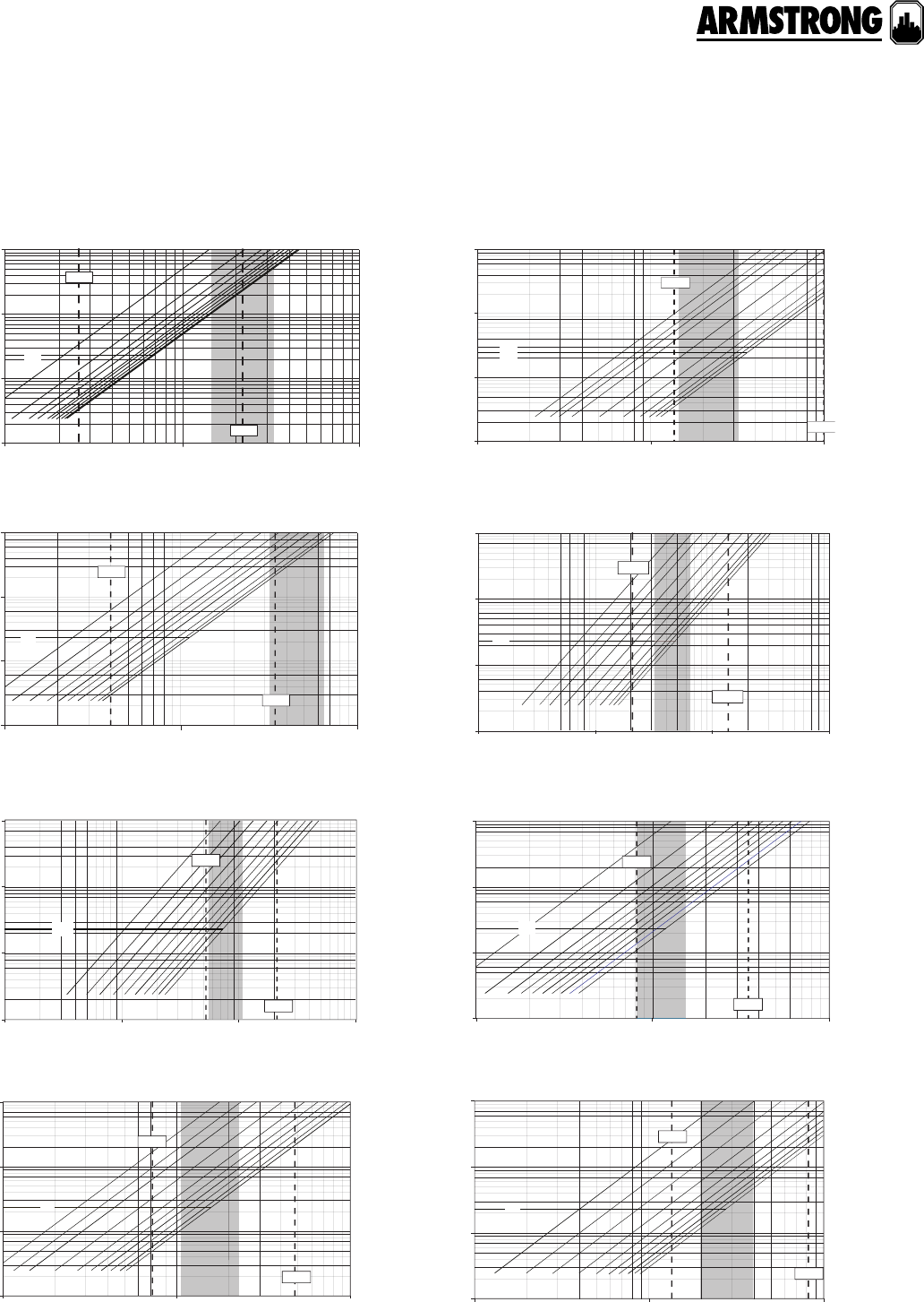
CIRCUIT BALANCING VALVES
VENTURI
|
SUBMITTAL
67
|
HYDRONIC SOLUTIONS CATALOG
performance curves
cbv050v(x)cr-lf
flow rate - gpm
max.
min.
pressure drop ft. of h
2
o
1
0.1
10
100
4.0
5.
0
3.
0
2.
0
1.0
0.5
cv
0.1
110
cbv075v(x)cr-lf
flow rate - gpm
max.
min.
pressure drop ft. of h
2
o
0.1
1
0.1
1
10
100
10
2.0
3.0
4.0
5.0
1.0
0.5
cv
cbv100v(x)cr
flow rate - gpm
max.
min.
pressure drop ft. of h
2
o
0.1
1
0.1
1
10
100
10
0
10
2.0
3.0
4.0
5.0
1.0
0.5
cv
cbv150v(x)cr
flow rate - gpm
max.
min.
pressure drop ft. of h
2
o
1
1
0.1
10
10
100
100
5.
0
4.0
3.0
2.0
1.0
0.5
cv
cbv050v(x)cr
flow rate - gpm
max.
min.
pressure drop ft. of h
2
o
0.1
1
0.1
1
10
100
10
3.
0
4.
0
5.
0
2.0
1.0
0.5
cv
cbv075v(x)cr
flow rate - gpm
max.
min.
pressure drop ft. of h
2
o
0.1
1
0.1
1
10
100
10
0
10
2.0
3.0
4.0
5.0
1.0
0.5
cv
cbv125v(x)cr
flow rate - gpm
max.
min.
cv
pressure drop ft. of h
2
o
1
0.1
1
10
100
100
10
2.0
3.0
4.0
5.0
1.0
0.5
cbv200v(x)cr
flow rate - gpm
max.
min.
cv
pressure drop ft. of h
2
o
1
0.1
1
10
100
10010
2.0
1.0
0.5
3.
0
4.
0
5.
0
68
|
HYDRONIC SOLUTIONS CATALOG
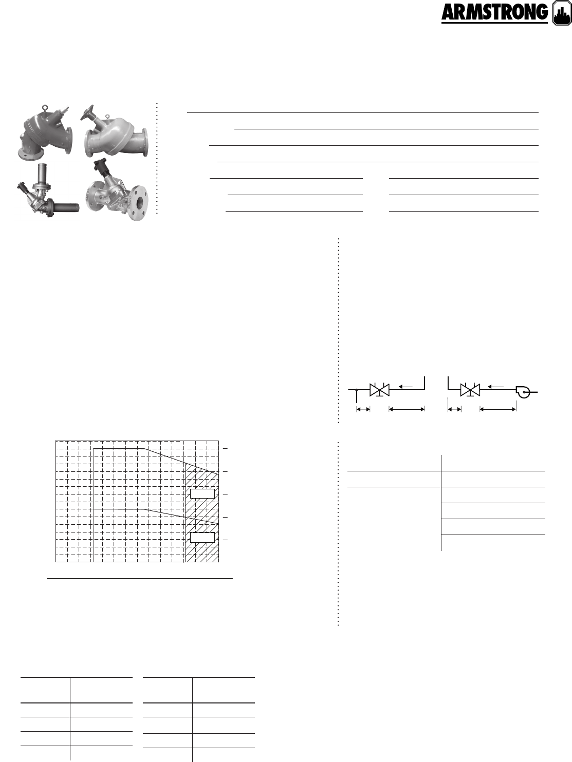
69
|
HYDRONIC SOLUTIONS CATALOG
CIRCUIT BALANCING VALVES
ANSI FLANGED
|
SUBMITTAL
Job:
Representative:
Engineer:
Contractor:
Order no: Date:
Submitted by: Date:
Approved by: Date:
materials of construction
ma ximum pump oper ating cond itions
Body: Cast iron astm a48 class 30b Disk: Bronze astmb584 c-84400
Seat: epdm** elastomer Stem: Brass - astm b -16
Trim: Brass astm b283 c-37700 O-ring: Buna & epdm** elastomer
Insulation: Optional fibre glass insulation with pvc cover
** epdm is not suitable for oil service.
175 psig at 230°f (1207 kPa at 110°c*)
*Optional Viton for 2½" to 6" sizes elastomers for temperatures up to 300°f (150°c)
temperature
pressure (psig)
pressure (bar)
25
400
300
200
100
0
20
15
10
5
0
3810-20 65 90 110 150
100500 150 200-50 250 300 (°f)
(°c)
viton
viton
b
a
a
legend: 2.5"– 12" ansi 125 flange
b
8"– 12" ansi 250 flange
operating parameters
Generally locate the valve five pipe diameters
downstream from a fitting; with two diameters
downstream from the balancing valve free
from fittings. If a balancing valve is located
downstream from a circulation pump, allow
a distance of ten (10) diameters between the
pump and balancing valves (as illustrated
below). To save space, the valve may be used
in the angled configuration as an elbow.
installation
cb
vc
bv
pump
5d 10d2d 2d
accessories
design data cbv straight and angle
pt ports
pt port extensions o 1O" o 2O"
Dierential pressure
manometers
cbdm 200
cbdm 135/60
dpm-15
dpm-100
Orifice Plates: 2½" to 12"
Venturis: 2½" to 12" butt welded
Pre-formed insulation is available to meet astm d 1784/
Class t4253-c, mea # 7-87, astm e-84 and astm e-136
with a flame spread rating of 25 or less and a smoke
development rating of 50 or less.
pipe size stem: no. of
360° turns
2.5 5
3 5
4 6
5 6
pipe size stem: no. of
360° turns
6 6
812
10 10
12 14
back to
contents
<
70
|
HYDRONIC SOLUTIONS CATALOG
CIRCUIT BALANCING VALVES
ANSI FLANGED
|
SUBMITTAL
dimension data - inches (mm)
model pipe
size
dimensions inches (mm) weight
ab
(full open) c d e f g s lbs (kg)
125 # ansi flange
cbv-2½fs 2.5 7. 38
(187) 9.62 (244) 2.75
(70)
4.63
(118)
1.0 0
(25)
2.56
(65)
7.0 0
(178)
12.00
(3 0 5)
33
(15)
cbv-2½fa
cbv-3fs 38.19
(208) 10.50 (267) 2.44
(62)
3.88
(99)
1.00
(25)
3.00
(76)
7.50
(191)
12.00
(305)
39
(17.7)
cbv-3fa
cbv-4fs 49.63
(245) 10.56 (268) 3.00
(76)
4.38
(111)
1.25
(32)
3.44
(87)
9.00
(229)
14.00
(356)
59
(26.8)
cbv-4fa
cbv-5fs 512.00
(305) 13.06 (332) 3.63
(92)
5.50
(140)
1.25
(32)
4.94
(125)
10.00
(254)
17. 50
(445)
108
(49)
cbv-5fa
cbv-6fs 614.13
(359) 13.75 (349) 4.44
(113)
6.63
(168)
2.00
(51)
5.88
(149)
11.00
(279)
20.69
(526)
167
(75.7)
cbv-6fa
cbv-8fs 819.00
(483) 24.62 (625) 5.69
(145)
9.19
(233)
2.25
(57)
7.8 8
(20 0)
13.50
(343)
28.00
(711)
344
(156)
cbv-8fa
cbv-10fs 10 20.33
(516) 26.50 (673) 6.56
(167)
9.78
(248)
2.25
(57)
9.47
(241)
16.00
(406)
30.01
(762)
603
(273)
cbv-10fa
cbv-12fs 12 24.07
(611) 28.43 (722) 7.63
(194)
14.05
(357)
2.25
(57)
12.63
(321)
19.00
(483)
38.09
(967)
1006
(456)
cbv-12fa
250 # ansi flange
cbv-8fs 819.11
(485) 24.62 (625) 5.69
(145)
9.69
(246)
2.25
(57)
7.8 8
(20 0)
15.00
(380)
28.20
(716)
396
(180)
cbv-8fa
cbv-10fs 10 20.33
(516) 26.50 (673) 6.56
(167)
9.80
(249)
2.25
(57)
9.47
(241)
17. 50
(445)
30.01
(762)
712
(323.6)
cbv-10fa
cbv-12fs 12 24.05
(611) 28.43 (722) 7.63
(194)
14.03
(356)
2.25
(57)
12.63
(321)
20.50
(521)
38.05
(966)
1163
(528.6)
cbv-12fa
c
s
b
f
g
(diameter)e
f
a
c
b
g
d
(diameter)
e
model cbv-fs - 2.5" to 6" model cbv-fa - 2.5" to 6"
model cbv-fs - 8" to 12" model cbv-fa - 8" to 12"
note: All dimensions are in inches (mm) and weights in lbs (kg). Dimensional tolerance up to ±0.125" (3mm).
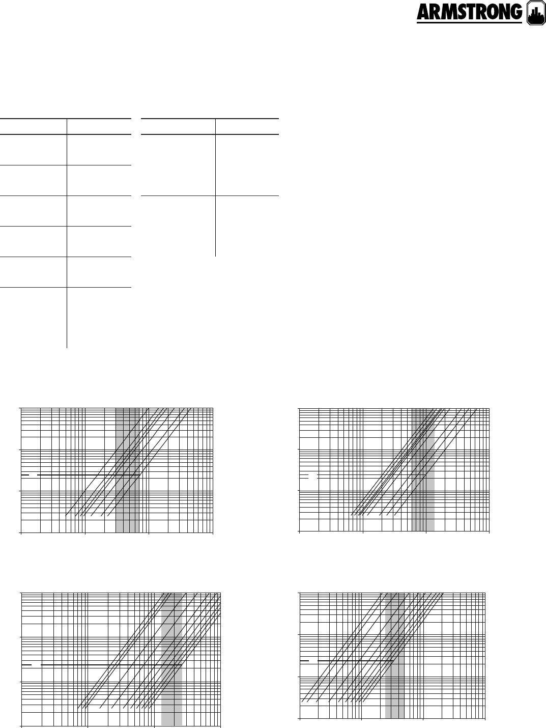
71
|
HYDRONIC SOLUTIONS CATALOG
CIRCUIT BALANCING VALVES
ANSI FLANGED
|
SUBMITTAL
model part number
cbv-2½fs 570109-376
cbv-2½fa 570109-476
cbv-3fs 570109-377
cbv-3fa 570109-477
cbv-4fs 570109-378
cbv-4fa 570109-478
cbv-5fs 570109-379
cbv-5fa 570109-479
cbv-6fs 570109-380
cbv-6fa 570109-480
cbv-8fs-125# 570109-381
cbv-8fa-125# 570109-481
cbv-8fs-250# 570109-661
cbv-8fa-250# 570109-681
model part number
cbv-10fs-125# 570109-382
cbv-10fa-125# 570109-482
cbv-10fs-250# 570109-662
cbv-10fa-250# 570109-682
cbv-12fs-125# 570109-383
cbv-12fa-125# 570109-483
cbv-12fs-250# 570109-663
cbv-12fa-250# 570109-683
part numbers
performance curves
cbv-2½fs/cbv-2½fa cbv-3fs/cbv-3fa
cbv-4fs/cbv-4fa cbv-5fs/cbv-5fa
4.0
5.0
3.0
2.0
1.0
pressure drop ft. of h
2
o
1
0.1
10
100
flow rate - gpm
110 100
1000
cv
4.0
5.0
3.0
2.0
1.0
pressure drop ft. of h
2
o
1
0.1
10
100
flow rate - gpm
110 100
1000
cv
4.0
5.0
6.0
3.0
2.0
1.0
pressure drop ft. of h
2
o
1
0.1
10
100
flow rate - gpm
110 100 1000
cv
4.0
6.0
5.0
3.0
2.0
1.0
pressure drop ft. of h
2
o
1
0.1
10
100
flow rate - gpm
10 100 1000
10000
cv
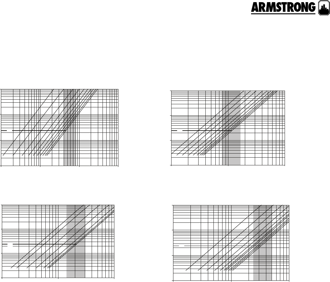
72
|
HYDRONIC SOLUTIONS CATALOG
CIRCUIT BALANCING VALVES
ANSI FLANGED
|
SUBMITTAL
performance curves
cbv-6fs/cbv-6fa
cbv-10fs/cbv-10fa
cbv-8fs/cbv-8fa
cbv-12fs/cbv-12fa
4.0
6.0
5.0
3.0
2.0
1.0
pressure drop ft. of h
2
o
1
0.1
10
100
flow rate - gpm
10 100 1000
10000
cv
4.0
6.0
5.0
3.0
10.0
8.0
7.0
pressure drop ft. of h
2
o
1
0.1
10
100
flow rate - gpm
100 1000 10000
cv
4.0
6.0
5.0
8.0
12.0
10.0
pressure drop ft. of h
2
o
1
0.1
10
100
flow rate - gpm
100 1000
10000
cv
4.0
3.0
2.0
5.0
6.0
7.0
8.0
10.0
12.0
14.0
pressure drop ft. of h
2
o
1
0.1
10
100
flow rate - gpm
100 1000
10000
cv
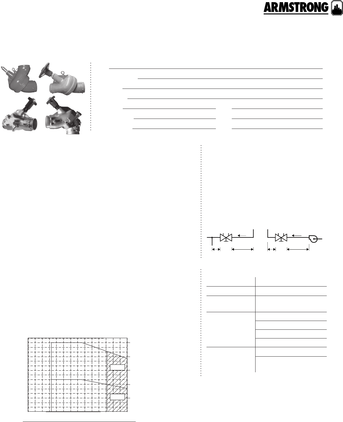
73
|
HYDRONIC SOLUTIONS CATALOG
CIRCUIT BALANCING VALVES
ANSI GROOVED
|
SUBMITTAL
Job:
Representative:
Engineer:
Contractor:
Order no: Date:
Submitted by: Date:
Approved by: Date:
materials of construction
ma ximum pump oper ating cond itions
Body: Ductile iron astm a536 gr65-45-12
Disk: Bronze astmb584 c-84400
Seat: Ultra high strength engineered resin
Stem: 2½"- 4" - Brass - astm b -16
5"- 12" - Stainless steel astm a582 type 416
Trim: Brass c-37700
O-ring: Buna
Insulation: Optional (pre-formed insulation is available to meet astm d
1784/class t4253-c, mea # 7-87, astm e-84 and astm e-136 with a flame
spread rating of 25 or less and a smoke development rating of 50 or less.)
pt ports ¼" (2): npt brass body with epdm** check and gasketted cap
** epdm is not suitable for oil service.
Max. working pressure: 375 psi (2586 kPa), limited to 175 psi (1207 kPa)
when used with Class 125/150 flange adapter
Max. working temperature: 230°f (110°c)*
*Optional viton for 2½" to 6" sizes elastomers for temperatures up to 300°f (150°c)
25
400
300
200
100
0
20
15
10
5
0
Body with ansi 125 ARMgrip flange adapter
Body alone, or with ansi 250
ARMgrip flange adapter
3810-20 65 90 11 0150
100500 150 200-50 250 300
temperature
pressure (psig)
pressure (bar)
(°f)
(°c)
viton
viton
b
a
a
legend:
b
operating parameters
Generally locate the valve five pipe diameters
downstream from a fitting; with two diameters
downstream from the balancing valve free
from fittings. If a balancing valve is located
downstream from a circulation pump, allow
a distance of ten (10) diameters between the
pump and balancing valves (as illustrated
below). To save space, the valve may be used
in the angled configuration as an elbow.
installation
cb
vc
bv
pump
5d 10d2d 2d
accessories
pt ports
pt port extensions o 1O" o 2O"
Armstrong flange
adapter
ansi125#, ansi250#
pn16, pn25
Dierential
pressure
manometers
cbdm 200
cbdm 135/60
dpm-15
dpm-100
Flow meters Orifice plates: 2½" to 12"
Venturis: 2½" to 12" butt
welded
back to
contents
<
74
|
HYDRONIC SOLUTIONS CATALOG
CIRCUIT BALANCING VALVES
ANSI GROOVED
|
SUBMITTAL
model part number
cbv-2½gs 570109-386
cbv-2½ga 570109-486
cbv-3gs 570109-387
cbv-3ga 570109-487
cbv-4gs 570109-388
cbv-4ga 570109-488
cbv-5gs 570109-389
cbv-5ga 570109-489
model part number
cbv-6gs 570109-390
cbv-6ga 570109-490
cbv-8gs 570109-391
cbv-8ga 570109-491
cbv-10gs 570109-392
cbv-10ga 570109-492
cbv-12gs 570109-393
cbv-12ga 570109-493
part numbers
dimension data - inches (mm)
model connection
sizes
dimensions inches (mm) weight
ab (open) c d e f lbs (kg)
cbv-2½gs dn65 12.00 (305) 9.62 (244) 2.75 (70) n/a 1.0 0 (25) 2. 56 (65) 19
(9.0)
cbv-2½ga 7.40 (187) 9.62 (244) 2.75 (70) 4.60 (117) 1.0 0 (25) 2.56 (65)
cbv-3gs dn80 12.00 (305) 10.50 (267) 2.44 (62) n/a 1.0 0 (25) 3.00 (76) 24
(11.0)
cbv-3ga 8.30 (208) 10.50 (267) 2.44 (62) 3.90 (98) 1.00 (25) 3.00 (76)
cbv-4gs dn100 14.00 (356) 10. 56 (268) 3.00 (76) n/a 1. 25 (32) 3.44 (87) 42
(19.0)
cbv-4ga 9.60 (244) 10. 56 (268) 3.00 (76) 4.30 (111) 1.25 (32) 3.44 (87)
cbv-5gs dn125 17.50 (445) 12.80 (324) 3.60 (92) n/a 1.25 (32) 4.94 (125) 81
(37.0)
cbv-5ga 12.00 (305) 12.80 (324) 3.60 (92) 5.50 (140) 1.25 (32) 4.94 (125)
cbv-6gs dn150 20.70 (525) 13.10 (332) 4.40 (113) n/a 2.0 0 (51) 5.88 (149) 54
(120)
cbv-6ga 14.10 (359) 13.10 (332) 4.40 (113) 6.63 (168) 2.00 (51) 5.88 (149)
cbv-8gs dn200 28.19 (716) 24.62 (625) 5.69 (144) n/a 2.00 (51) 7.88 (200) 310
(141)
cbv-8ga 18.93 (481) 24.62 (625) 5.69 (144) 9.19 (233) 2.00 (51) 7.88 (200)
cbv-10gs dn250 30.00 (762) 26.50 (673) 6.60 (167) n/a 2.0 0 (51) 9.47 (241) 460
(209)
cbv-10ga 20.30 (516) 26.50 (673) 6.60 (167) 9.80 (248) 2.0 0 (51) 9.47 (241)
cbv-12gs dn300 38.10 (967) 28.40 (722) 7.60 (194) n/a 2.0 0 (51) 12.63 (321) 870
(395)
cbv-12ga 24.10 (611) 28.40 (722) 7.60 (194) 14.00 (356) 2.0 0 (51) 12.63 (321)
note: All dimensions are in inches (mm) and weights in lbs (kg). Dimensional tolerance up to ±0.125" (3mm).
connection
sizes
stem: no. of
360° turns Kv (open) Cv (open) min. flow rate max. flow rate
l/s (usgpm) l/s (usgpm)
dn65 5 60 70 1.9 (30) 4 .4 (71)
dn80 5 8 5 10 0 3.8 (60) 8.8 (140)
dn100 5 23 9 28 0 8.2 (130) 17.0 (270)
dn125 5 281 3 3 0 15.8 (250) 31.6 (500)
dn150 5 3 92 4 6 0 25.2 (400) 50.5 (800)
dn200 5 1024 120 0 50.5 (800) 107.3 (1700)
dn250 5 1877 220 0 94.7 (1500) 189.3 (3000)
dn300 5 2 815 3 3 0 0 151.4 (2400) 315.5 (5000)
flow rate ranges
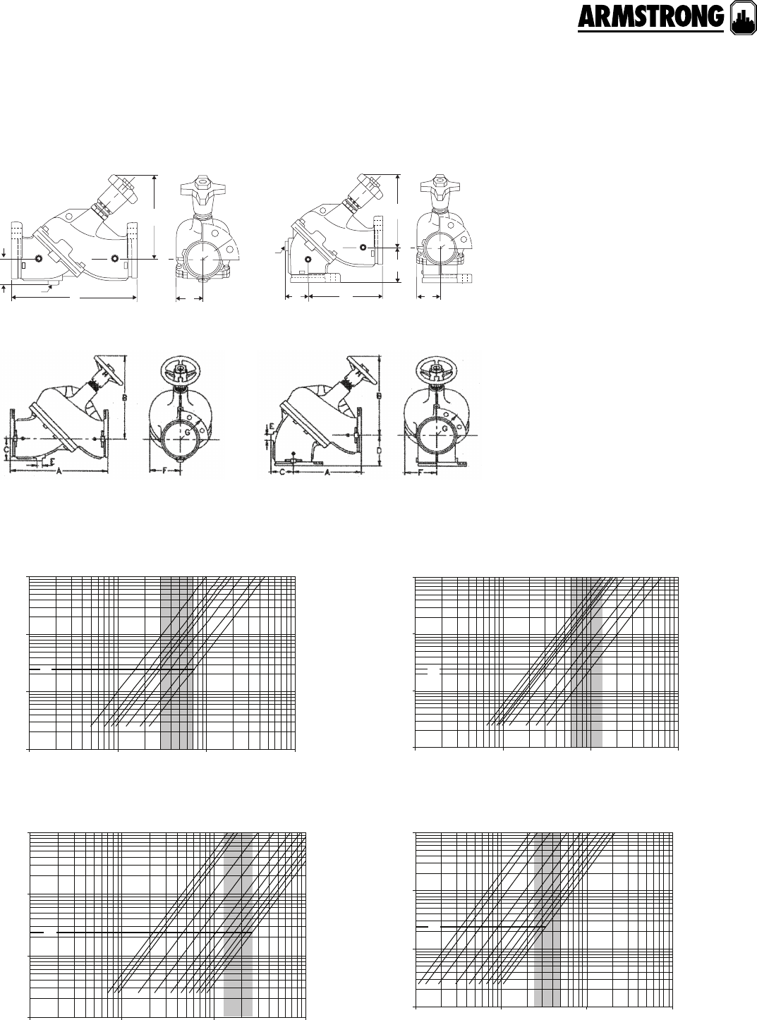
75
|
HYDRONIC SOLUTIONS CATALOG
CIRCUIT BALANCING VALVES
ANSI GROOVED
|
SUBMITTAL
performance curves
cbv-2½gs/cbv-2½ga cbv-3gs/cbv-3ga
cbv-4gs/cbv-4ga cbv-5gs/cbv-5ga
model cbv-gs - 2.5" to 6" model cbv-ga - 2.5" to 6"
f
a
c
b
d
e
c
a
b
f
e
model cbv-fs - 8" to 12" model cbv-fa - 8" to 12"
4.0
5.0
3.0
2.0
1.0
pressure drop ft. of h
2
o
1
0.1
10
100
flow rate - gpm
110 100
1000
cv
4.0
5.0
3.0
2.0
1.0
pressure drop ft. of h
2
o
1
0.1
10
100
flow rate - gpm
110 100
1000
cv
4.0
5.0
6.0
3.0
2.0
1.0
pressure drop ft. of h
2
o
1
0.1
10
100
flow rate - gpm
110 100 1000
cv
4.0
6.0
5.0
3.0
2.0
1.0
pressure drop ft. of h
2
o
1
0.1
10
100
flow rate - gpm
10 100 1000
10000
cv

76
|
HYDRONIC SOLUTIONS CATALOG
CIRCUIT BALANCING VALVES
ANSI GROOVED
|
SUBMITTAL
performance curves
cbv-6gs/cbv-6ga
cbv-10gs/cbv-10ga
cbv-8gs/cbv-8ga
cbv-12gs/cbv-12ga
4.0
6.0
5.0
3.0
2.0
1.0
pressure drop ft. of h
2
o
1
0.1
10
100
flow rate - gpm
10 100 1000
10000
cv
4.0
6.0
5.0
3.0
10.0
8.0
7.0
pressure drop ft. of h
2
o
1
0.1
10
100
flow rate - gpm
100 1000 10000
cv
4.0
6.0
5.0
8.0
12.0
10.0
pressure drop ft. of h
2
o
1
0.1
10
100
flow rate - gpm
100 1000
10000
cv
4.0
3.0
2.0
5.0
6.0
7.0
8.0
10.0
12.0
14.0
pressure drop ft. of h
2
o
1
0.1
10
100
flow rate - gpm
100 1000
10000
cv
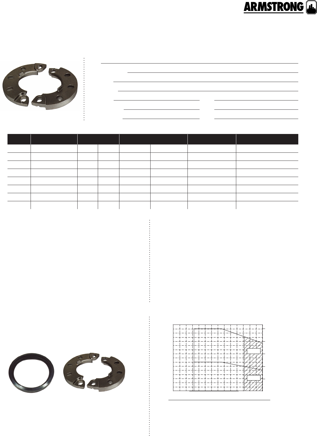
77
|
HYDRONIC SOLUTIONS CATALOG
ARMGRIP™ FLANGE ADAPTER KITS
ANSI 125 & 250
|
SUBMITTAL
Job:
Representative:
Engineer:
Contractor:
Order no: Date:
Submitted by: Date:
Approved by: Date:
technical data
Flange: Ductile iron astm a536 gr65-45-12
Connection: Industry standard grooves
Gasket: standard temperature: epdm
high temperature: Viton® or equal
25
400
300
200
100
0
20
15
10
5
0
Body with ansi 125 ARMgrip flange adapter
Body alone, or with ansi 250 ARMgrip flange adapter
3810-20 65 90 11 0150
100500 150 200-50 250 300
temperature
pressure (psig)
pressure (bar)
(°f)
(°c)
viton
viton
b
a
a
legend:
b
pressure/temperature
ARMgrip™ Flange Adapter Kits quickly convert industry standard
grooved pipe connections to flanged connections, as required to
suit application requirements. Armstrong grooved products (such
as cbv-g, afo-g, ftv-g and ssg) include special tabs that engage
the flange adapter to prevent rotation during installation, just like a
fixed flange. While grooved connection components may provide
the greatest initial and installed cost economy, optional ARMgrip™
flange adapters enable the widest range of on-site application
versatility, while reducing spare parts costs and inventory.
Armstrong component grooves comply with the following
pipe standards for cut groove connections:
• ansi b36.10
• bs1387 (iso65)
• din2440 & 2448 (iso4200)
• jis g3452
Some pipe standards have more than one o.d. per nominal
pipe size. Always specify pipe o.d. to match component
grooves connections.
application
groove specifications
model size inches (mm) ansi rating temperature rating quantity identification
fa2.5 2.5 (63.5) 125 250 Standard High Temp
fa3 3.0 (76.2) 125 250 Standard High Temp
fa4 4.0 (101.6) 125 250 Standard High Temp
fa5 5.0 (127.0) 125 250 Standard High Temp
fa6 6.0 (152.4) 125 250 Standard High Temp
fa8 8.0 (203.2) 125 250 Standard High Temp
fa10 10.0 (254.0) 125 250 Standard High Temp
fa12 12.0 (304.8) 125 250 Standard High Temp
® Viton is a registered trademark of DuPont Performance Elastomers.
flange adapter
gasket
armstrong ductile iron
flange adapter
back to
contents
<
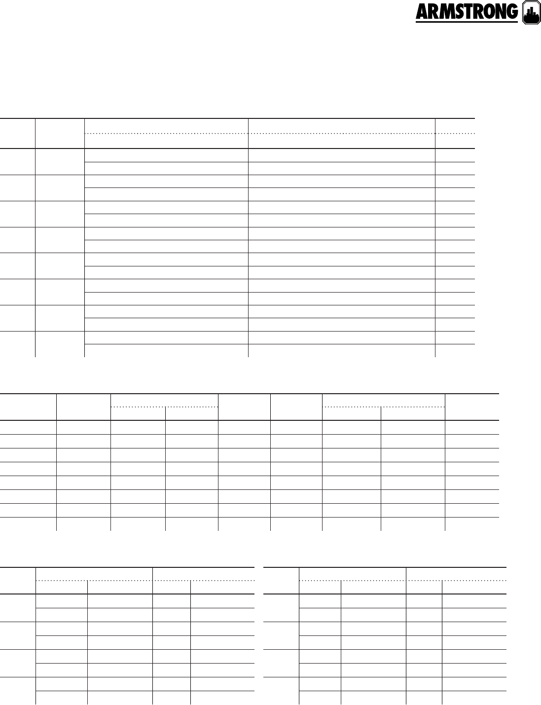
78
|
HYDRONIC SOLUTIONS CATALOG
ARMGRIP™ FLANGE ADAPTER KITS
ANSI 125 & 250
|
SUBMITTAL
model ansi pn
rating part number rating part number
fa2.5 ansi 125** 570204-000 pn 16 570204-000
ansi 250 570205-000 pn 25 570204-000
fa3 ansi 125 570206-000 pn 16 570206-500
ansi 250 570207-000 pn 25 570206-500
fa4 ansi 125*** 570208-000 pn 16 570208-000
ansi 250 570209-000 pn 25 570209-500
fa5 ansi 125*** 570210-000 pn 16 570210-500
ansi 250 570211-000 pn 25 570211-500
model ansi pn
rating part number rating part number
fa6 ansi 125 570212-000 pn 16 570212-000
ansi 250 570213-000 pn 25 570213-500
fa8 ansi 125 570214-000 pn 16 570214-500
ansi 250 570215-000 pn 25 570229-500
fa10 ansi 125 570228-000 pn 16 570228-500
ansi 250 570229-000 pn 25 570229-500
fa12 ansi 125 570230-000 pn 16 570230-500
ansi 250 570231-000 pn 25 570231-500
part numbers
armgrip™ flange adapter kits*
model pipe o.d. flange bolt holes weight
rating o.d. thickness b.c.d size number lbs (kg)
fa2.5 73 (2.9) ansi 125** 7.25 (184) 0.88 (22) 5.72/5.50 (146/140)†0.75 (19) 4 Slots 7 (3)
ansi 250 7.50 (190) 1.00 (25) 5.88 (149) 0.88 (22) 87 (3)
fa3 89 (3.5) ansi 125 7.50 (190) 0.88 (22) 6.00 (152) 0.75 (19) 48 (4)
ansi 250 8.25 (210) 1.12 (29) 6.62 (168) 0.88 (22) 88 (4)
fa4 114 (4.5) ansi 125*** 9.00 (229) 0.94 (24) 7.50/7.10 (191/180)†0.75 (19) 8 Slots 9 (4)
ansi 250 10.00 (254) 1.25 (32) 7.88 (200) 0.88 (22) 820 (9)
fa5 142 (5.6) ansi 125*** 10.00 (254) 0.94 (24) 8.50 (216) 0.88 (22) 811 (5)
ansi 250 11.00 (279) 1.38 (35) 9.26 (235) 0.88 (22) 822 (10)
fa6 168 (6.6) ansi 125 11.00 (279) 1.00 (25) 9.50 (241) 0.88 (22) 813 (6)
ansi 250 12.50 (318) 1.44 (37) 10.62 (270) 0.88 (22) 12 24 (11)
fa8 219 (8.6) ansi 125 13.50 (343) 1.12 (29) 11.74 (298) 0.88 (22) 818 (8)
ansi 250 15.00 (381) 1.63 (41) 13.0 (330) 1.00 (25) 12 36 (16)
fa10 273 (10.8) ansi 125 16.00 (406) 1.19 (30) 14.24 (361) 1.00 (25) 12 24 (11)
ansi 250 17.50 (444) 1.88 (48) 15.25 (387) 1.12 (29) 16 51 (23)
fa12 324 (12.8) ansi 125 19.00 (483) 1.25 (32) 17.0 0 (432) 1.00 (25) 12 51 (23)
ansi 250 20.50 (521) 2.00 (51) 17.74 (451) 1.25 (32) 16 75 (34)
* All dimensions are in inches (mm) and weights in lbs (kg).
** Also fits pn16 and pn25
*** Also fits pn16
† Bolt holes are elongated
†† ±0.03 (±0.76)
nominal
sizes pipe o.d. o.d. tolerance gasket
seat††
groove
width††
groove diameter groove
depth
+ - dimension tolerance
2.50 (65) 2.90 (73) 0.01 (0.13) 0.01 (0.13) 0.6 (15.88) 0.3 (7.92) 2.7 (68.83) ±0.005 (0.13) 0.08 (2.11)
3.00 (80) 3.50 (89) 0.01 (0.25) 0.01 (0.25) 0.6 (15.88) 0. 3 (7.92) 3.3 (84.68) ±0.010 (0.25) 0.08 (2.11
4.00 (100) 4.50 (115) 0.01 (0.25) 0.01 (0.25) 0.6 (15.88) 0.4 (9.52) 4.3 (110.1) ±0.010 (0.25) 0.09 (2.3)
5.00 (125) 5.80 (142) 0.01 (0.13) 0.01 (0.13) 0.6 (15.88) 0.4 (9.52) 5.4 (136.8) ±0.005 (0.13) 0.10 (2.41)
6.00 (150) 6.60 (168 0.01 (0.25) 0.01 (0.25) 0.6 (15.88) 0.4 (9.52) 6.4 (163.7) ±0.010 (0.25) 0.09 (2.29)
8.00 (200) 8.60 (219) 0.03 (0.79) 0.03 (0.79) 0.8 (19.05) 0.4 (11.18) 8.4 (214.4) -0.64 (0.02) 0.09 (2.34)
10.00 (250) 10.80 (273) 0.06 (1.60) 0.03 (0.79) 0.8 (19.05) 0.5 (12.70) 10.6 (268.3) -0.69 (0.03) 0.09 (2.39)
12.00 (300) 12.80 (324) 0.09 (2.36) 0.03 (0.79) 0.8 (19.05) 0.5 (12.70) 12.5 (318.3) -0.76 (0.03) 0.11 (2.78)
armstrong cut groove connections*
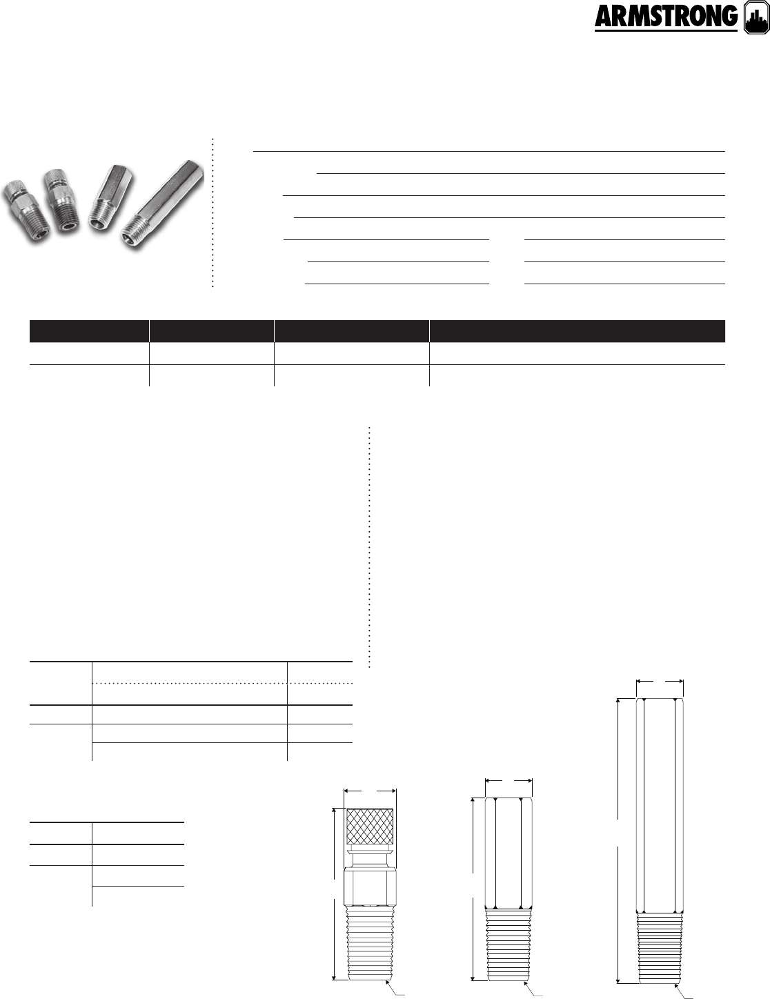
79
|
HYDRONIC SOLUTIONS CATALOG
PT PORT AND EXTENSIONS
|
SUBMITTAL
Job:
Representative:
Engineer:
Contractor:
Order no: Date:
Submitted by: Date:
Approved by: Date:
material of construction
technical data
Body and cap: Brass astm b-16 h02 c36000
Seal: epdm
Maximum operating pressure: 300 psi (2068 kPa)
20 bar (pn20)
Operating temperature range: -4°f to 300°f
(-20°c to 150°c)
Armstrong pt ports enable the quick connection of pressure
and temperature measuring instruments for testing, balancing,
and troubleshooting hydronic systems. The dual epdm seals
provide superior protection against leaks in either heated or
chilled water systems, and are compatible with water and
ethylene or propylene glycol anti-freeze solutions. The ¼" npt
male mounting thread mates with common pipe fittings and
the V" flared thread port mates with compatible instrument
probes such as those used with an Armstrong dpm dierential
pressure manometer. Two sizes of ¼" npt m × f extensions are
available to improve the accessibility of pt ports that are mounted
in hard-to-reach locations or where pipe insulation is used.
pt ports & extensions
model no. quantity tag no. comments
dimension data - inches (mm)
part numbers
model dimensions inches (mm) weight
a b c oz. (g)
pt port 0.5 (13) 1.54 (39) N" npt 1.0 (28)
pt port
extension
0.5 (13) 1.75 (44) N" npt 1.2 (34)
0.5 (13) 2.75 (70) N" npt 2.0 (58)
model item number
pt port 570148-004
pt port
extension
570148-200
570148-201
pt port 1.75" pt port extension 2.75" pt port extension
cc
aa
b
b
c
a
b
back to
contents
<
80
|
HYDRONIC SOLUTIONS CATALOG
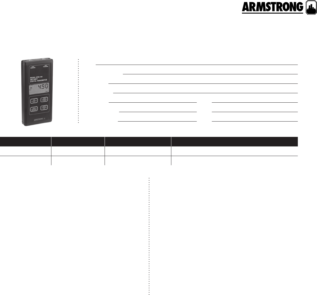
81
|
HYDRONIC SOLUTIONS CATALOG
DIFFERENTIAL PRESSURE MANOMETER
SUBMITTAL
Job:
Representative:
Engineer:
Contractor:
Order no: Date:
Submitted by: Date:
Approved by: Date:
material of construction
carrying case, hoses & fittings
Service: Compatible, non-combustible gases & liquids
Wetted materials: Type 316l stainless steel
Accuracy: ±0.5% of full scale from 60°f - 78°f (15°c - 25°c);
±1% of full scale from 32°f - 60°f and 78°f - 104°f
(0°c - 15°c and 25°c - 40°c)
Measurement range: dpm-100: 0 - 100 psi (0 - 689 kPa)
dpm-15: 0 - 15 psi (0 - 103 kPa)
Maximum pressure: dpm-100: 200 psi (1379 kPa)
dpm-15: 30 psi (207 kPa)
Selectable pressure units: psi, in. H2O, in. Hg, mm Hg, kPa,
bar and mbar
Operating temperature range: 32°f to 200°f (0°c to 93°c)
Storage temperature: -4°f to 176°f (-20°c to 80°c)
Pressure hysteresis: ±0.1% of full scale
Connections: Two V" female npt
Adapters: Two ¼" male sae adapters included
Display: 0.42" (10.6 mm) 4½ digit lcd with units indicators
Power source: 9 V alkaline battery (included)
Battery life: Up to 100 hours (less when lcd backlight used)
Agency approvals: ce
The Dierential Pressure Manometer (dpm) is a rugged,
digital instrument used to measure the pressure drop or
pressure gain across hydronic system components. The
dpm is available in either 0-15 psi or 0-100 psi measurement
range models for precise adjustment of circuit balancing
valves, and to monitor circulator performance. Both models
measure gauge or dierential pressure and can store up to
40 readings for later recall. The operator can select from
a variety of Imperial and metric measurement units to suit
the hydronic system design data. Valuable safety features
include visible and audible instrument over-range warning
alarms and backlit display for work in poorly illuminated
areas. The lightweight, compact dpm design is easy to
use in the tight, overhead spaces commonly encountered
when balancing or troubleshooting hydronic systems.
• Case is made of durable resin material
• Includes impact resistant foam packing
• Flexible hoses (one red and one blue) complete with fittings:
- ¼" female sae flare straight fitting (connects to ¼"sae
adapters on meter)
- ¼" female sae 45° elbow fitting (connects to measuring probes)
• Two pressure measuring probes with adapter fittings
• One Armstrong cbv balancing wheel
• One Armstrong ARMflo venturi-style cbv balancing slide rule
model no. quantity tag no. comments
back to
contents
<
82
|
HYDRONIC SOLUTIONS CATALOG
DIFFERENTIAL PRESSURE MANOMETER
SUBMITTAL
dimension data - inches (mm)
part numbers
model height width depth weight
dpm-15 meter only 5.88 (150) 2.75 (70) 0.88 (20) 0.90 (0.4)
dpm-15 with case & hose fit 13.50 (343) 17.00 (432) 4.50 (114) 5.85 (2.6)
dpm-100 meter only 5.88 (150) 2.75 (70) 0.88 (20) 0.90 (0.4)
dpm-100 with case & hose fit 13.50 (343) 17.00 (432) 4.50 (114) 5.85 (2.6)
model part numbers
dpm-15 meter only 570095-201
dpm-15 with case & hose fit 570095-202
dpm-100 meter only 570095-206
dpm-100 with case & hose fit 570095-207
dpm-15 and dpm-100 with case & hose fit 570095-208
All dimensions are in inches (mm) and weights are in lbs (kg)
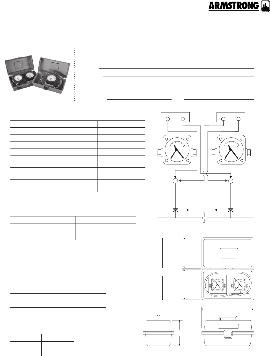
83
|
HYDRONIC SOLUTIONS CATALOG
PORTABLE FLOW MEASUREMENT METER
CBDM 200 & CBDM 135/60
|
SUBMITTAL
Job:
Representative:
Engineer:
Contractor:
Order no: Date:
Submitted by: Date:
Approved by: Date:
material of construction
item cbdm 200 cbdm* 135/60
Gauge Aluminum body, s.s.316
internals, buna-n seals
One polysulfone body and one
aluminum body, both with s.s.
internals and with buna-n seals
Tubing Nylon
Fittings Brass
Filters 90 micron
Hoses buna-n with neoprene jacket and ‘Schrader’ ¼" brass
couplet. (Connects with ¼" 37° flare male fitting).
specification
item cbdm 200 cbdm* 135/60
Range 0-200 0-135" 0-60"
Diameter 2½"4½"
Hose length 5" 5"
Adapters Schrader to ¼" pmp Schrader to ¼" pmp
Max. operating
pressure 500 psi 300 psi
Max. operating
temperature 150°f (66 °c) 150°f (66 °c)
Accuracy ±5% ascenting 0-135": ±5% ascenting
0-200": ±5% ascenting
* Two meters in one case
armstrong cbv circuit balancing valve
pressure guage connections cbdm 135/60
d
a
c
c
b
low high low high
low green
flow
(downstream)
high red
(upstream)
dimension data - inches
model a b c d
cbdm 200 12.50 6.00 7.00 14.00
cbdm 135/60 16.50 7. 25 9.00 18.50
part numbers
model item number
cbdm 200 570095-003
cbdm 135/60 570095-001
84
|
HYDRONIC SOLUTIONS CATALOG
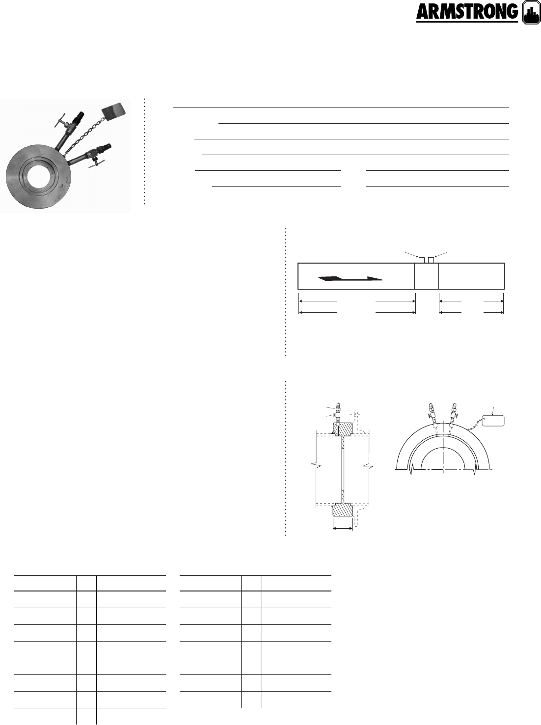
85
|
HYDRONIC SOLUTIONS CATALOG
ORIFICE INDICATORS
|
SUBMITTAL
Job:
Representative:
Engineer:
Contractor:
Order no: Date:
Submitted by: Date:
Approved by: Date:
ma ximum pump oper ating cond itions
250 psi at 250°f (1724 kPa at 121°c)
When sizing an Armstrong Venturi, model apo, for a given pipe
size, locate the operating gpm on the performance curve. Select the
apo with a pressure drop (P) as near to, but always above 10".
Example: 120 gpm on 4" pipe sizes available.
4"- 804 w/6.75"P
4"- 712 w/13"P- preferred choice
4"- 619 w/31"P
Use Armstrong Indicators for measuring flow conditions to obtain
proper distribution and balance throughout all sections of a
hydronic system.
Each unit includes a set of V" nipples, and disconnects. All models
greater than 1" are equipped with isolation valves.
All dimensions in inches.
Construction: ½" to 2"= Brass npt connectors
2½" to 10"= Zinc plate steel, for flange sandwich or socket weld.
mounting orientation
apo - 2½" to apo - 24"
sizing information
general information
part numbers
red green
flow
*2
**4
*5
**10"
minimum pipe diameters from fitting or valve
*½"−4" *5" and up
apo - 2½" to apo- 24"
¾"
disconnect
met
al identification
tag
valve
model apart number
APO 2½-708 ¾ 570132-000
APO 3-653 ¾ 570132-001
APO 4-619 ¾ 570132-002
APO 2½-810 ¾ 570132-003
APO 3-734 ¾ 570132-004
APO 3-794 ¾ 570132-005
APO 4-712 ¾ 570132-006
APO 4-804 ¾ 570132-007
model apart number
APO 5-750 ¾ 570132-008
APO 6-750 ¾ 570132-009
APO 8-800 ¾ 570132-010
APO 10-775 ¾ 570132-011
APO 12-792 ¾ 570132-012
APO 14-800 ¾ 570132-013
APO 16-800 ¾570132-014
back to
contents
<
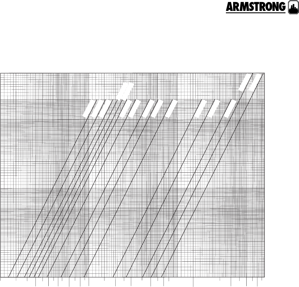
86
|
HYDRONIC SOLUTIONS CATALOG
ORIFICE INDICATORS
|
SUBMITTAL
2½"-708
2½"-810
3"-653
3"-734
4"-619
3"-794
4"-712
4"-804
5"-750
6"-750
8"-800
10"-775
12"-792 14"-800
16"-800
100
200
150
90
80
70
60
50
40
30
20
15
10
9
8
7
6
5
4
3
2
1
10 15 20
25 35 45 60 80 100 200 300 500 700 900 1500 2500 4000 6000 8000
30 40 50 70 90 150 250 400 600 800 1000 2000 3000 5000 7000 9000
gpm water
permanent head loss - inches water
mete reading - inches of water p
performance curves
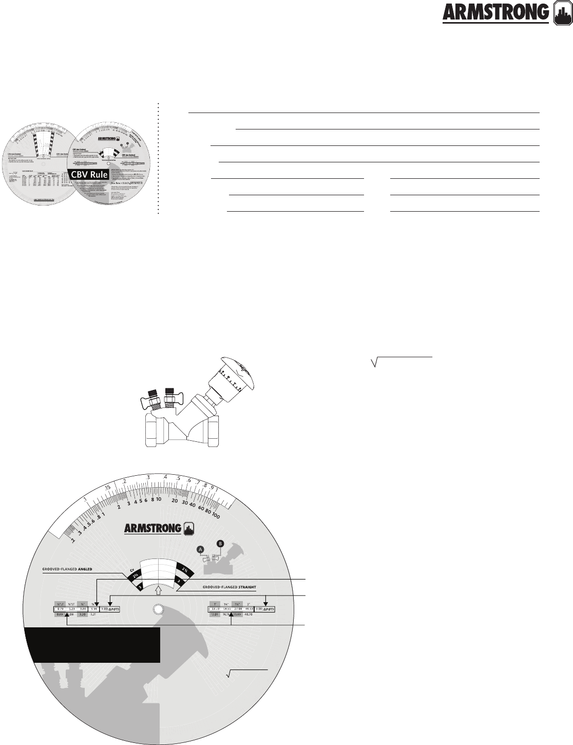
87
|
HYDRONIC SOLUTIONS CATALOG
CBV BALANCING WHEEL
CBV FLOW MEASUREMENT
|
SUBMITTAL
Job:
Representative:
Engineer:
Contractor:
Order no: Date:
Submitted by: Date:
Approved by: Date:
1 Measure the dierential pressure (
p) across ports a & b
(fig. 1) of the ARMflo cbv.
2 Using the cbv Rule, turn the wheel of the slide rule
(fig. 2) until the measured pressure drop appears in
window. For example, for the slide rule shown in fig. 2,
the wheel is turned reveal 3.00 in the window.
3 Read the flow for the particular size of valve installed.
In this case, the reading
for a O" valve would be
5.96 USgpm.
4 The flow calculation for
other valve sizes appear
on either side of the
center rivet.
5 In the event that the calculated flow is not within the
desired range, turning the handle clockwise will decrease
the flow and turning the handle anticlockwise will increase
the flow.
Alternatively, or if a more precise flow rate calculation is
required, use the flow rate formula and corresponding Cv
value for the cbv model measured.
Flow rate = 0.66 Cv
Flow rate : USgpm
P: Dierential pressure (ft of h2o)
D: Density of liquid (lb/ft3)
D/62.4: 1 for water at 60°f (16°c)
0.66: Conversion constant
Cv : cbv flow co-ecient
ARMflo Circuit Balancing Valves (cbv)
include an integral venturi for dieren-
tial pressure to flow rate correlation.
Compared to traditional variable orifice
valves, the handle turns position is not
required for flow rate calculation.
The venturi design also results in higher
flow measurement accuracy (especially
when throttled), correctly indicates
valve plugging conditions, and enables
faster and move accurate flow mea-
surement, CBV adjustment, system
balancing and troubleshooting.
Accurate balancing contributes to
greater occupant comfort, system
eciency and life expectancy.
½"-2" circuit balancing valves
CBV size (inches)
CBV size (inches)
CBV Rule
Armstrong Circuit Balancing Valves include an integral fixed orifice
venturi for dierential pressure to flowrate correlation.
Compared to traditional variable orifice valves, the handle
turns position is not required for flow rate calculation.
This design enables faster and more accurate flow
measurement, cbv adjustment, system balancing and
troubleshooting.
Accurate balancing contributes to greater
occupant comfort, system eciency and
life expectancy.
Flow Rate = 0.66CV∆P/(d/62.4)
instructions (For balancing purposes only)
Use Armstrong performance curves for valve pressure drop determination
and size selection.
1. Measure the dierential pressure across ports a & b of the cbv.
2.
Slide the wheel to the nearest corresponding value in the
∆
p(ft) window.
3. Read the flow rate conversions (feet to USgpm) in the red USgpm
window for the cbv model measured.
Alternatively, or if a more precise flow rate calculation is
required, use the flow rate formula and corresponding
Cv value for the cbv model measured.
flow rate: USgpm
∆P: dierential pressure (ft)
d: density of liquid (lb/ft3)
d/62.4: 1 for water at 60˚f (16˚c)
0.66: conversion constant
Cv: cbv flow co-ecient
©
2
0
1
3
a
r
m
s
t
r
o
n
g
fl
u
i
d
t
e
c
h
n
o
l
o
g
y
|
p
n
:
5
7
0
1
0
9
-
2
0
3
(
f
e
e
t
o
f
w
a
t
e
r
)
m
e
t
e
r
g
a
u
g
e
r
e
a
d
i
n
g
fl
o
w
r
a
t
e
(
g
p
m
)
Valve handwheel setting
instructions
1. Place hairline over valve setting opposite cbv size.
2. Read flow rate (gpm) opposite meter gauge reading.
USgpm
size
Cv
USgpm
size
Cv
Flow Rate for O"
cbv = 5.96 USgpm
Flow Rate for other
sizes between ½"
and 2" sizes
Δp = 3.0 ft
P/(d/62.4)
fig. 1
fig. 2
back to
contents
<
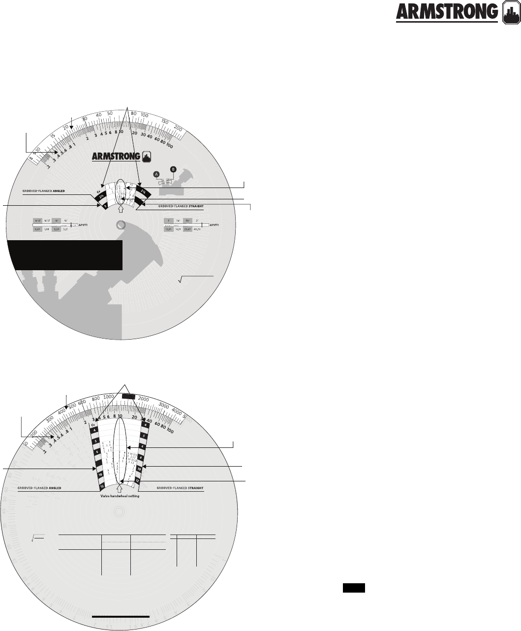
88
|
HYDRONIC SOLUTIONS CATALOG
CBV BALANCING WHEEL
CBV FLOW MEASUREMENT
|
SUBMITTAL
2½" & 3" circuit balancing valves
(fig. 3)
1 Measure the dierential pressure (
P) in the
pipe with an appropriate measuring device.
2 Determine whether straight or angled
configuration is used.
3 Set the hairline over the valve handwheel setting
of the size and configuration of the valve.
4 In this case we have a 3" straight valve with a
handwheel setting of “3”. The Meter Gauge
Reading is 10 ft.
5 Read across from 10 on the lower scale to reveal
a Flow rate of 6 USgpm.
6 In the event that the calculated flow is not within
the desired range, turning the handle clockwise
will decrease the flow and turning the handle
anticlockwise will increase the flow.
4"-12" circuit balancing valves
(fig. 4)
1 The process is the same as with the 2½ & 3"
valves. Measure the dierential pressure (
P) in
the pipe with an appropriate measuring device.
2 Determine whether straight or angled configura-
tion is used.
3 Set the hairline over the valve handwheel setting
of the size and configuration of the valve.
4 In this case we have a 8" angled valve with a
handwheel setting of “7”. The Meter Gauge
Reading is 15 ft.
5 Read across from 15 on the lower scale to reveal
a Flow rate of 1550 USgpm.
6 In the event that the calculated flow is not within
the desired range, turning the handle clockwise
will decrease the flow and turning the handle
anticlockwise will increase the flow.
60
CBV size (inches)
CBV size (inches)
3
valve size
CBV Rule
Armstrong Circuit Balancing Valves include an integral fixed orifice
venturi for dierential pressure to flowrate correlation.
Compared to traditional variable orifice valves, the handle
turns position is not required for flow rate calculation.
This design enables faster and more accurate flow
measurement, cbv adjustment, system balancing and
troubleshooting.
Accurate balancing contributes to greater
occupant comfort, system eciency and
life expectancy.
Flow Rate = 0.66CV∆P/(d/62.4)
instructions (For balancing purposes only)
Use Armstrong performance curves for valve pressure drop determination
and size selection.
1. Measure the dierential pressure across ports a & b of the cbv.
2.
Slide the wheel to the nearest corresponding value in the
∆
p(ft) window.
3. Read the flow rate conversions (feet to USgpm) in the red USgpm
window for the cbv model measured.
Alternatively, or if a more precise flow rate calculation is
required, use the flow rate formula and corresponding
Cv value for the cbv model measured.
flow rate: USgpm
∆P: dierential pressure (ft)
d: density of liquid (lb/ft3)
d/62.4: 1 for water at 60˚f (16˚c)
0.66: conversion constant
Cv: cbv flow co-ecient
©
2
0
1
3
a
r
m
s
t
r
o
n
g
fl
u
i
d
t
e
c
h
n
o
l
o
g
y
|
p
n
:
5
7
0
1
0
9
-
2
0
3
(
f
e
e
t
o
f
w
a
t
e
r
)
m
e
t
e
r
g
a
u
g
e
r
e
a
d
i
n
g
fl
o
w
r
a
t
e
(
g
p
m
)
Valve handwheel setting
instructions
1. Place hairline over valve setting opposite cbv size.
2. Read flow rate (gpm) opposite meter gauge reading.
USgpm
size
Cv
USgpm
size
Cv
meter gauge
scale
valve handle
position
straight
valves
angl
ed
valves
hairlin
e
flow rate
scale
valve handle
position
straight
valves
hairlin
e
meter gauge
scale
angl
ed
valves
1500
dp (psi)
d
gpm = cv
cv valve coecient
(gpm at 1 psi pressure drop)
cv=1.16 kv
d=Density of the
liquid with d=1 for
water at 60˚f
(
f
e
e
t
o
f
w
a
t
e
r
)
m
e
t
e
r
g
a
u
g
e
r
e
a
d
i
n
g
fl
o
w
r
a
t
e
(
g
p
m
)
CBV size (inches) CBV size (inches)
instructions
1. Place hairline over valve setting opposite cbv size.
2. Read flow rate (gpm) opposite meter gauge reading.
°F
°C
C%
0
10
20
30
40
50
40
4.5
Cg
1.0
.99
.99
.98
.97
.96
70
21
Cg
1.0
.99
.99
.98
.97
.96
70
21
Cg
1.0
.99
.99
.99
.98
.98
180
82
Cg
1.01
1.01
1.0
1.0
.99
.98
40
4.5
Cg
1.0
.99
.99
.99
.98
.97
180
82
Cg
1.01
1.01
1.01
1.01
1.0
1.0
propylene
ethelene
Glycol corrections
gpm (actual) = gpm (tested) × Cg
model
2½" – 12"
pipe size
inches
cv fully
open
minimum flow
1ft pressure drop
50% open
gpm
100% open
gpmgpm
pressure
drop (ft)
velocity
(ft/s)
7.0
7.0
7.0
7.8
8.8
7.05
7.32
7.45
2½
3
4
5
6
8
10
12
cbv 2½ g/a
cbv 3 g/a
cbv 4 g/a
cbv 5 g/a
cbv 6 g/a
cbv 8 g/a
cbv 10 g/a
cbv 12 g/a
69.0
97.0
255.0
324.0
449.0
1127.0
2050.0
3125.0
18.0
19.0
46.0
60.0
100.0
307.0
559.0
1532.0
46.0
64.0
180.0
220.0
300.0
751.0
1347.0
2059.0
100.0
160.0
275.0
500.0
800.0
1100.0
1800.0
2600.0
4.5
11.0
2.8
5.5
7.0
2.1
1.8
1.5
maximum
recommended flow
valv e sizing chart
armstrongfluidtechnology.com
valve size
flow rate
scale
8
fig. 3
fig. 4
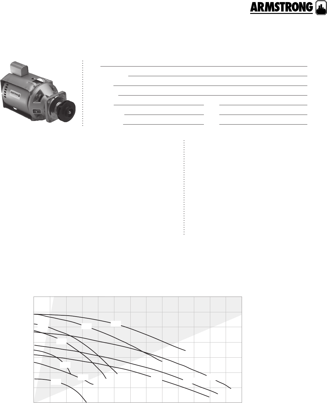
S&H CIRCULATOR LESS VOLUTE
KIT
|
SUBMITTAL
89
|
HYDRONIC SOLUTIONS CATALOG
Job:
Representative:
Engineer:
Contractor:
Order no: Date:
Submitted by: Date:
Approved by: Date:
Armstrong in-line circulators are favoured by
system designers and chiller/boiler manu-
facturers who prefer 3-piece construction for
reliability, eciency, and serviceability. Today’s
models are direct substitutes for all compat-
ible circulators built over the last 50 years.
Armstrong Gold Series - Pump Less Volute kits
enable you to upgrade and renew circulators
manufactured by others, to gain the benefits of
Armstrong quality, service, and performance,
along with these design innovations.
materials of construction
ma ximum pump oper ating cond itions
125 psig at 225°f (863 kPa at 107°c)
0
(9.1) 30
(6.1) 20
(3.0) 10
(0.0) 0 20 40 60 80 100 120
(7.57)
(6.31)
(5.05)
(3.78)(2.52)
(1.26)(0.00)
flow USgpm (l/s)
total head feet (m)
p
referred sele
c
ti
o
n are
a
S2H3
H4
S4S4
H5
H5H5H5
S5
performance curve
Pump body: Gold painted steel, radially split for servicing ease
Motor: Maintenance-free, permanently lubricated
Sealed bearing assembly: Armstrong sba with universal bearing module
• Stainless steel face plate
• Alloy steel shaft (heat treated for long life)
• Copper sleeve
• Circular oil wick
Coupler: 4-spring or flexible coupler
Shaft: Alloy steel (heat treated for long life), copper sleeve
Mechanical seal: Carbon/SiC, stainless steel trim, Viton seal
Impeller: Noryl (registered trade mark of ge plastics)
back to
contents
<
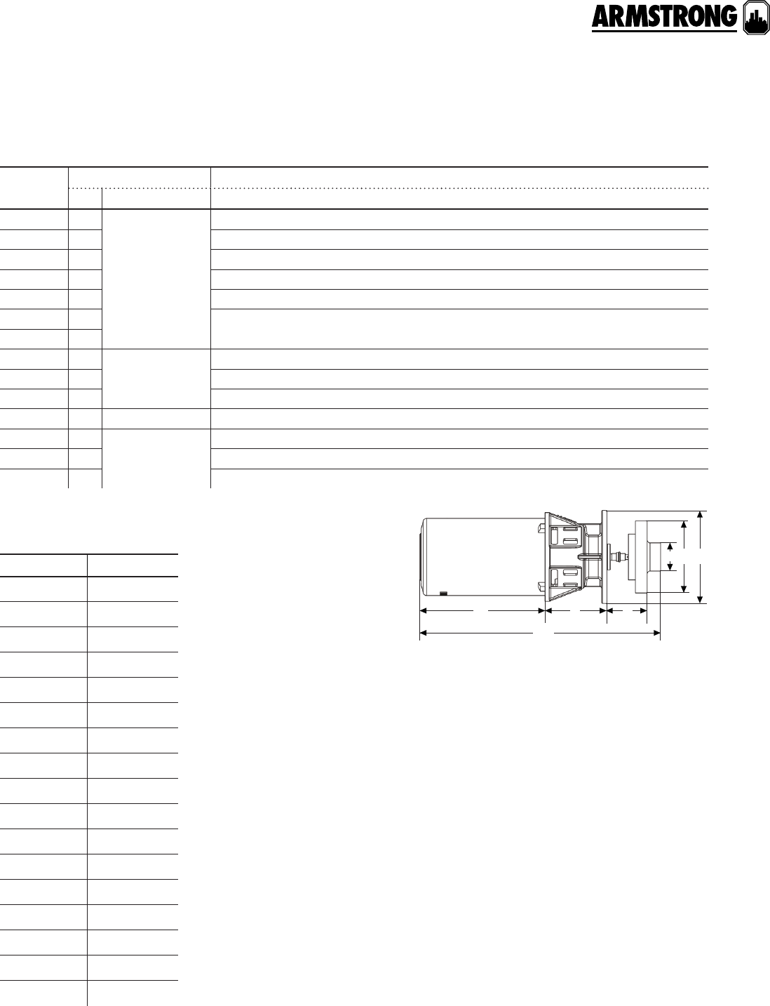
S&H CIRCULATOR LESS VOLUTE
KIT
|
SUBMITTAL
90
|
HYDRONIC SOLUTIONS CATALOG
model part number
S25 LV 110116-200
H32 LV 110116-201
H41 LV 110116-202
S45 LV 110116-203
S46 LV 110116-204
H51 LV 110116-300
H52 LV 110116-301
H53 LV 110116-302
H53–3 LV 110116-303
H54 LV 110116-304
H54–3 LV 110116-305
S55 LV 110116-306
S55–3 LV 110116-307
Raypak 1110108-675
Raypak 2110108-677
Raypak 3110108-717
Raypak 4110108-680
part numbers
dimension data - inches (mm)
d f
ebg
a
c
model motor* dimensions inches (mm)
hp phase and volt a b c d e f g
S25 LV A⁄ab
1 phase 115 v
6.12(155) 2.75(70) 12.62(321) 3.88(98) 1.25(31) 1.25(33) 3.38(86)
H32 LV T7.50(190) 3.38(86) 13.88(354) 3.38(84) 1.38(36) 1.75(44) 4.25(107)
H41 LV T7.50(190) 4.25(108) 14.12(358) 3.38(84) 1.25(32) 1.75(44) 5.38(135)
S45 LV N7.50(190) 4.25(108) 14.25(360) 3.38(84) 2.00(50) 1.75(45) 5.38(135)
S46 LV L7.50(190) 5.25(135) 14.25(360) 3.38(84) 2.00(50) 1.75(45) 5.38(135)
H51 LV N7.50(190) 5.25(135) 15.62(396) 4.62(117) 2.12(53) 1.75(43) 6.88(173)
H52 LV L
H53 LV K1 phase 115/230 v
or 3 phase 208-
230/460 v
5.12(130) 5.25(135) 13.12(333) 4.62(117) 2.12(53) 1.75(43) 6.88(173)
H54 LV O10.38(235) 5.25(135) 17.75(452) 4.62(117) 2.12(53) 2.12(54) 6.88(173)
S55 LV K8.25(210) 5.25(135) 16.75(426) 4.62(117) 2.12(53) 2.12(54) 6.88(173)
Raypak 1** L 1 phase 115 v 7.50(190) 4.38(112) 14.75(375) 4.62(117) 2.12(53) 2.12(54) 6.88(173)
Raypak 2** K 1 phase 115/208-
230 v
9.88(251) 4.50(115) 17.25(439) 4.62(117) 2.12(53) 2.12(54) 6.88(173)
Raypak 3** O 10.38(235) 4.50(115) 17.75(452) 4.62(117) 2.12(53) 2.12(54) 6.88(173)
Raypak 4** K 9.25(235) n/a n/a 4.62(117) n/a n/a n/a
Dimensions shown are for reference only.
*All single phase motors are equipped with built-in thermal overload
protection. Three phase motors require external overload protection.
** Base circulator: 2b 1050 ab- lv

COMPANION FLANGES
PARTS INFORMATION
91
|
HYDRONIC SOLUTIONS CATALOG
cast iron flanges application guide
cast iron pipe size and part number (for single flanges/flange kits) hardware
kit #
b & g
fasterner
kit #
model 0.75" 1.0" 1.25" 1.5" 2.0" 2.5" 3.0"
Astro 230/
250CI/CI-R/
280/210/286/
Compass
116013-011 116012-011 116011-011 116009-011 810120-202 p15696
E7/E8/E9/
E12/E12-TE /
E14/E14-TE/
E15/ E17
116013-011 116012-011 116011-011 116009-011 810120-244 p64910
E10/E11/E13 /
E19/E21/E22/
E23/E24/
Astro 290
106073-011 104300-011 104301-011 810120-204 p64940
E16 106074-011 810120-206 f91600
E28/E29 105188-011 810120-208 p65129
E30 (2")/
E33 (2") 106074-011 810120-212 n/a
E30 (3")/
E33 (3") 105188-011 810120-208 p65129
H-32 BF 106073-011 104300-011 104301-011 810120-218 p64930
H-41 BF 116012-011 810120-210 p64230
H-51 BF 116012-011 810120-218 n/a
H-52 BF 116011-011 810120-218 p64910
H-53 BF n/a 810120-218 p64930
H-54 BF 106074-011 810120-212 n/a
H-63 BF /
H-64 BF /
H-65 BF
104301-011 810120-204 n/a
H-66 BF / H-67
BF / H-68 BF 106074-011 810120-212 n/a
S-25 BF 116013-011 116012-011 116011-011 116009-011 810120-202 p15696
S-35 BF 105210-011 810120-206 f91600
S-45 BF 105189-011 105188-011 810120-208 p65129
S-46 BF/
S-55 BF/
S-57 BF
105188-011 810120-208 p65129
S-69 BF 133615-010 810120-214 p09540
(A hardware kit is included in each flange kit.)
back to
contents
<

COMPANION FLANGES
PARTS INFORMATION
92
|
HYDRONIC SOLUTIONS CATALOG
lead free bronze flanges application guide
bronze pipe size and part number (for single flanges/flange kits) hardware
kit #
b & g
fasterner
kit #
model 0.75" 1.0" 1.25" 1.5" 2.0" 2.5" 3.0"
Astro
230SS/250SS/
210/280/286/
Compass
116013-041 116012-041 116011-041 116009-041 810120-202 p15696
E7B/E8B/E9B/
E12B/ E14B/
E12B-TE /E14B-
TE /E15B/E17B
116013-041 116012-041 116011-041 116009-041 810120-244 p64910
E10B / E11B /
E13B / E19B /
E21B / E22B /
E23B / E24B /
Astro 290
106073-041 104300-041 104301-041 810120-204 p64940
E16B 106074-041 810120-206 f91600
E28B / E29B 105188-041 810120-208 p65129
E30B (2")/
E33 B(2") 106074-041 810120-212 n/a
E30B (3")/
E33B (3") 105188-041 810120-208 p65129
H-32 AB 106073-041 104300-041 104301-041 810120-218 p64930
H-41 AB 116012-041 810120-210 p64230
H-51 AB 116012-041 810120-218 n/a
H-52 AB 116011-041 810120-218 p64910
H-53 AB n/a 810120-218 p64930
H-54 AB 106074- 041 810120-212 n/a
H-63 AB /
H-64 AB /
H-65 AB
104301-041 810120-204 n/a
H-66 AB /
H-67 AB /
H-68 AB
106074-041 810120-212 n/a
S-25 AB 116013-041 116012-041 116011-041 116009-041 810120-202 p15696
S-35 AB 105210-041 810120-206 f91600
S-45 AB 105189-041 105188-041 810120-208 p65129
S-46 AB / S-55
AB / S-57 AB 105188-041 810120-208 p65129
S-69 AB 106466-041 810120-214 p09540
(A hardware kit is included in each flange kit.)
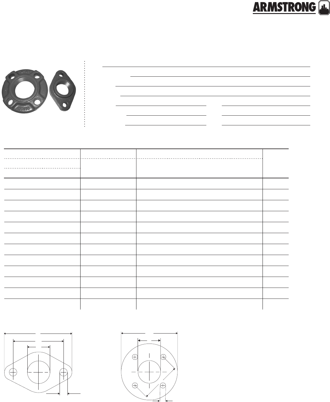
COMPANION FLANGES
PARTS INFORMATION
93
|
HYDRONIC SOLUTIONS CATALOG
Job:
Representative:
Engineer:
Contractor:
Order no: Date:
Submitted by: Date:
Approved by: Date:
individual flange dimensions
armstrong bell & gossett dimension inches (mm)
diagramcast iron bronze cast iron bronze a b c d
part number part number
104300-011 104300-041 p03300 p06660 1.25 (32) 3.44 (87) 4.75 (121) 0.50 (13) 1
104301-011 104301-041 p03410 p06690 1.50 (38) 3.44 (87) 4.75 (121) 0.50 (13) 1
105188-011 105188-041 f74000 f74800 3.00 (76) 5.06 (128) 6.00 (152) 0.56 (14) 2
105189-011 105189-041 p03560 p06750 2.50 (63) 5.06 (128) 6.00 (152) 0.56 (14) 2
105210-011 105210-041 — — 2.00 (51) 3.75 (95) 4.88 (124) 0.56 (14) 2
106073-011 106073-041 p01500 p06620 1.00 (25) 3.44 (87) 4.75 (121) 0.50 (13) 1
106074-011 106074-041 — — 2.00 (51) 3.16 (80) 5.13 (130) 0.63 (16) 2
116009-011 116009-041 p03430 p03450 1.50 (38) 3.16 (80) 4.25 (108) 0.50 (13) 1
116011-011 116011-041 p03250 p06640 1.25 (32) 3.16 (80) 4.25 (108) 0.50 (13) 1
116012-011 116012-041 p01510 —1.00 (25) 3.16 (80) 4.25 (108) 0.50 (13) 1
116013-011 116013-041 p00740 —0.75 (19) 3.16 (80) 4.25 (108) 0.50 (13) 1
133615-010 106466-041 a24600 —3.00 (76) 6.00 (152) 7.50 (190) 0.75 (19) 2
cc
a
b
a
d
d
b
diagram
1diagram 2
94
|
HYDRONIC SOLUTIONS CATALOG
FLANGES KITS
CROSS REFERENCE
|
PARTS INFORMATION
FLANGE HARDWARE KITS
APPLICATION CHARTS
|
PARTS INFORMATION
95
|
HYDRONIC SOLUTIONS CATALOG
hardware kit (were used) cast iron
model part number
S-25 BF Flange Hardware kit # 810120-202
B&G Fastener kit # P15696
S-35 BF Flange Hardware kit # 810120-206
B&G Fastener kit # F91600
S-45 BF Flange Hardware kit # 810120-208
B&G Fastener kit # P65129
S-46 BF / S-55 BF / S-57 BF Flange Hardware kit # 810120-208
B&G Fastener kit # P65129
S-69 BF Flange Hardware kit # 810120-214
B&G Fastener kit # P09540
(A hardware kit is included in each flange kit.)
hardware kit (application chart) lead free bronze
model part number
Astro 20B / 30B / 50B / 70B Flange Hardware kit # 810120-202
B&G Fastener kit # P15696
E7B / E8B / E9B / E12B / E14B /
E12B-TE / E14B-TE / E15B / E17B Flange Hardware kit # 810120-244
B&G Fastener kit # P64910
E10B / E11B / E13B / E19B /
E21B / E22B / E23B / E24B Flange Hardware kit # 810120-204
B&G Fastener kit # P64940
E16B Flange Hardware kit # 810120-206
B&G Fastener kit # F91600
E28B / E29B Flange Hardware kit # 810120-208
B&G Fastener kit # P65129
E30B (2") / E33B (2") Flange Hardware kit # 810120-212
B&G Fastener kit # n/a
E30B (3") / E33B (3") Flange Hardware kit # 810120-208
B&G Fastener kit # P65129
H-32 AB Flange Hardware kit # 810120-218
B&G Fastener kit # P64930
H-41 AB Flange Hardware kit # 810120-210
B&G Fastener kit # P64230
H-51 AB Flange Hardware kit # 810120-218
B&G Fastener kit # n/a
H-52 AB Flange Hardware kit # 810120-218
B&G Fastener kit # P64910
H-53 AB Flange Hardware kit # 810120-218
B&G Fastener kit # P64930
Continued on next page...
back to
contents
<

FLANGE HARDWARE KITS
APPLICATION CHARTS
|
PARTS INFORMATION
96
|
HYDRONIC SOLUTIONS CATALOG
hardware kit (application chart) lead free bronze
model part number
H-54 AB Flange Hardware kit # 810120-212
B&G Fastener kit # n/a
H-63 AB / H-64 AB /
H-65 AB Flange Hardware kit # 810120-204
B&G Fastener kit # n/a
H-66 AB / H-67 AB /
H-68 AB Flange Hardware kit # 810120-212
B&G Fastener kit # n/a
S-25 AB Flange Hardware kit # 810120-202
B&G Fastener kit # P15696
S-35 AB Flange Hardware kit # 810120-206
B&G Fastener kit # F91600
S-45 AB Flange Hardware kit # 810120-208
B&G Fastener kit # P65129
S-46 AB / S-55 AB / S-57 AB Flange Hardware kit # 810120-208
B&G Fastener kit # P65129
S-69 AB Flange Hardware kit # 810120-214
B&G Fastener kit #
(A hardware kit is included in each flange kit.)
FLANGE HARDWARE KITS
CROSS REFERENCE
|
PARTS INFORMATION
97
|
HYDRONIC SOLUTIONS CATALOG
810120-202 hardware kit (b&g fastener kits p15696)
810120-204 hardware kit (b&g fastener kits p15696)
810120-206 hardware kit (b&g fastener kits p15696)
810120-208 hardware kit (b&g fastener kits p15696)
810120-210 hardware kit (b&g fastener kits p15696)
part number description quantity pump model
116653-000 Gasket flange 2S-25,Astro 20,
Astro 30, Astro 50
911123-112 hhcs G/af - 14 × 1.5" lcs 4
913523-100 hh jam nut G/af - 14 lcs 4
part number description quantity pump model
104034-000 Gasket flange 2H-63, H-64, H-65
E10, E11, E13
911123-114 hhcs G/af - 14 × 1.75" lcs 4
913523-100 hh jam nut G/af - 14 lcs 4
part number description quantity pump model
105209-002 Gasket flange 2
S-35 E16, E30, E33 911125-118 hhcs K - 13 × 2.25" lcs 8
913125-100 hh nut K - 13 lcs 8
part number description quantity pump model
105201-000 Gasket flange 2S-45, S-46 S-55,
S-57
911125-120 hhcs K - 13 × 2.5" lcs 8
913125-100 hh nut K - 13 lcs 8
part number description quantity pump model
105176-000 Gasket flange 2
H-41911123-114 hhcs G/af - 14 × 1.75" lcs 4
913523-100 hh jam nut G/af - 14 lcs 4
back to
contents
<
FLANGE HARDWARE KITS
CROSS REFERENCE
|
PARTS INFORMATION
98
|
HYDRONIC SOLUTIONS CATALOG
810120-212 hardware kit (b&g fastener kits p15696)
810120-214 hardware kit (b&g fastener kits p15696)
810120-216 hardware kit (b&g fastener kits p15696)
810120-218 hardware kit (b&g fastener kits p15696)
810120-244 hardware kit (b&g fastener kits p15696)
part number description quantity pump model
116117-000 Gasket flange 2H-54, H-66, H-67,
H-68, 4360-2B,
1050-2B
911125-118 hhcs K - 13 × 2.25" lcs 8
913125-100 hh nut K - 13 lcs 8
part number description quantity pump model
105201-000 Gasket flange 2
S-69 911129-120 hhcs X - 11 × 2.5" lcs 8
913129-100 hh nut X - 11 unc 8
part number description quantity pump model
426410-008 Gasket flange 2
1060-3D 911129-120 hhcs X - 11 × 2.5" lcs 8
913129-100 hh nut X - 11 unc 8
part number description quantity pump model
105176-001 Gasket flange 2H-32, H-51, H-52, H-53 E7,
E8, E9, E12, E14 4360-1.25B,
4360-1.5B, 4360-2B
911123-114 hhcs G/af - 14 × 1.75" lcs 4
913523-100 hh jam nut G/af - 14 lcs 4
part number description quantity pump model
105176-000 Gasket flange 2
E7, E8, E9, E12, E14 911123-112 hhcs G/af - 14 × 1.5" lcs 4
913523-100 hh jam nut G/af - 14 lcs 4
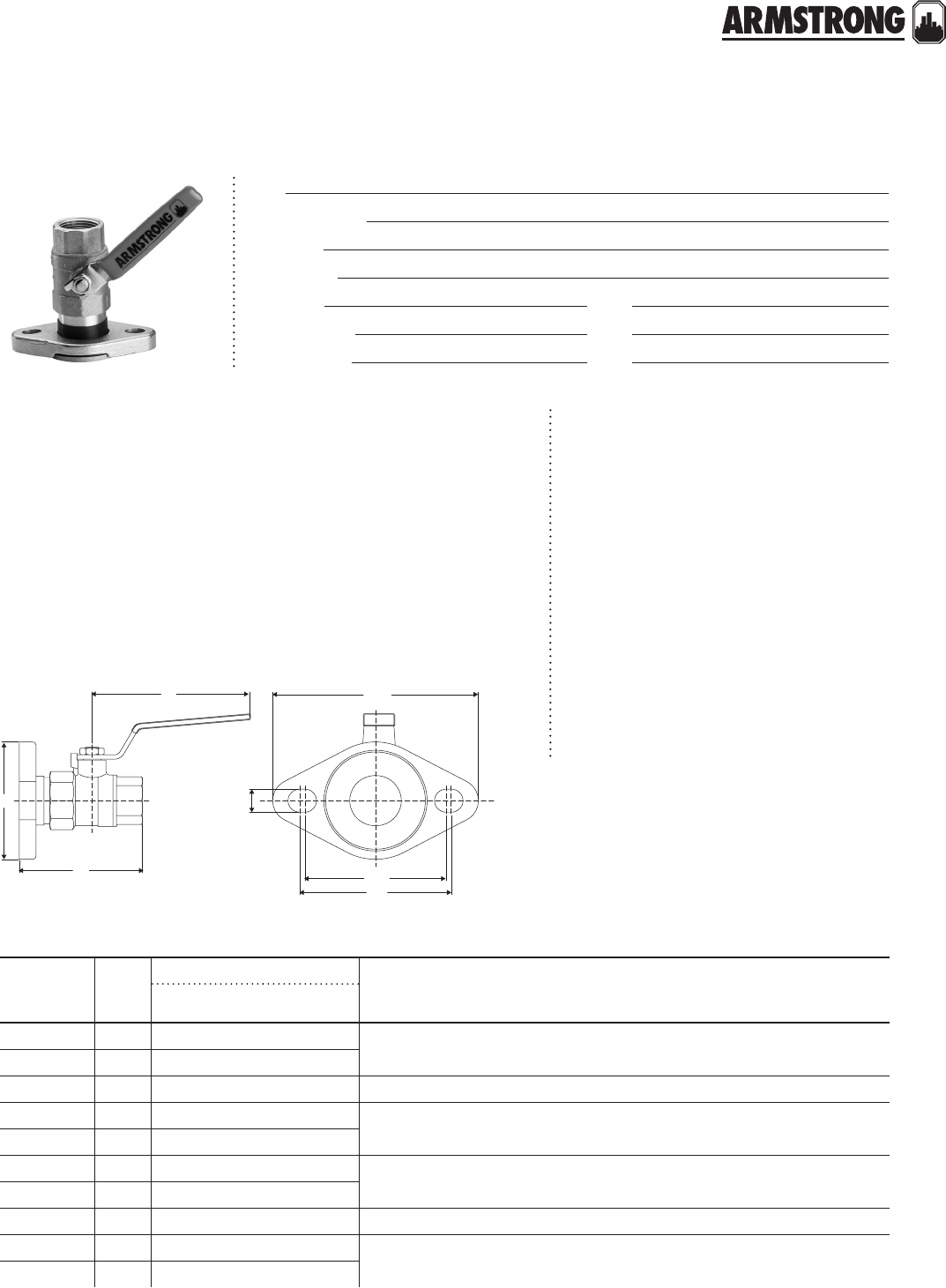
FLEX FLANGE
|
SUBMITTAL
99
|
HYDRONIC SOLUTIONS CATALOG
Job:
Representative:
Engineer:
Contractor:
Order no: Date:
Submitted by: Date:
Approved by: Date:
The Flex Flange is for industry professionals
who need a fast and convenient solution for
pump installation and isolation.
The Flex Flange provides value by helping
plumbing installers:
• Perform quick upgrades and repairs
• Reduce downtime
• Increase client operating eciency
• Reduce the overall hydronic system cost
The Flex Flange includes an optimized integral
check valve to reduce fluid pressure drop,
flow restriction and pump capacity loss.
This feature prevents gravity circulation and
reverse system flow.
Valve and stem: Brass
Flange: Cast iron/Chromate
Ball: Chrome plated brass
Stem o-rings: buna n
Seat: ptfe
material of construction
ma ximum pump oper ating cond itions
150 psig at 250°f (1034 kPa at 121°c)
dimension data - inches (mm)
size type
a
b c d e f g
iso
(without check)
iso
(with check)
K" (DN15) npt 2.56 (65) 2.77 (70) 2.70 (69) 3.54 (90) 4.63 (118) 3.18 (81) 3.41 (87) 0.53 (13)
O" (DN20) npt 2.94 (75) 3.43 (87)
1" (DN25) npt 3.50 (89) 4.17 (106) 2.70 (69) 4.53 (115) 4.63 (118) 3.18 (81) 3.41 (87) 0.53 (13)
1N" (DN32) npt 4.03 (102) 4.94 (126) 2.70 (69) 5.51 (140) 4.63 (118) 3.18 (81) 3.41 (87) 0.53 (13)
1K" (DN40) npt 4.31 (110) 5.24 (133)
K" (DN15) Sweat 2.45 (62) 2.67 (68) 2.70 (69) 3.54 (90) 4.63 (118) 3.18 (81) 3.41 (87) 0.53 (13)
O" (DN20) Sweat 3.04 (77) 3.54 (90)
1" (DN25) Sweat 3.69 (94) 4.38 (111) 2.70 (69) 4.53 (115) 4.63 (118) 3.18 (81) 3.41 (87) 0.53 (13)
1N" (DN32) Sweat 4.16 (106) 5.07 (129) 2.70 (69) 5.51 (140) 4.63 (118) 3.18 (81) 3.41 (87) 0.53 (13)
1K" (DN40) Sweat 4.56 (116) 5.49 (139)
g
b
c
f
e
a
d
All dimensions are in inches (mm)
back to
contents
<
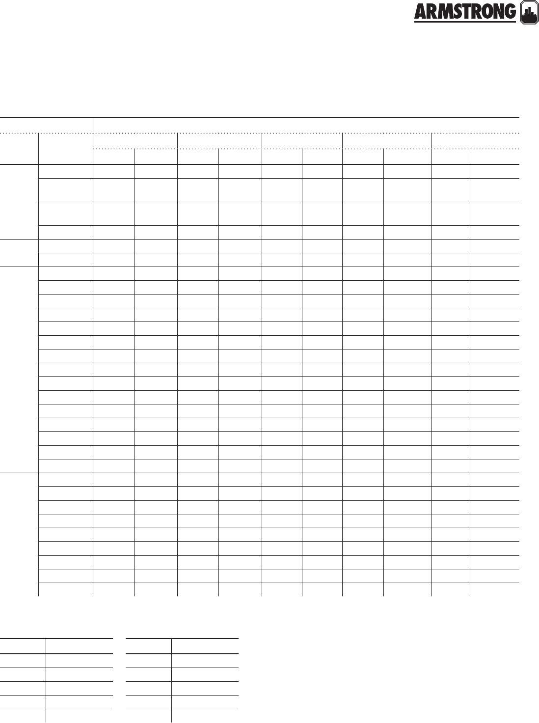
FLEX FLANGE
|
SUBMITTAL
100
|
HYDRONIC SOLUTIONS CATALOG
application chart
circulator the armstrong flex flange kits
series models FF-050T / FF-050S FF-075T / FF-075S FF-100T / FF-100S FF-125T / FF-125S FF-150T / FF-150S
K" npt K" Sweat O" npt O" Sweat 1" npt 1" Sweat 1N" npt 1N" Sweat 1K" npt 1K" Sweat
Astro
20F/20BF ● ● ● ● ● ●
30/30B,
30-3/30B-3 ● ● ● ● ● ●
50/50B,
50-3/50B-3 ● ● ● ● ● ●
70/ 70B ● ● ● ● ● ●
Astro 2 230SS ● ● ● ● ● ● ● ● ● ●
250SS ● ● ● ● ● ● ● ● ● ●
E series
E7/E7B ● ● ● ● ● ● ● ●
E8/E8B ● ● ● ● ● ● ● ●
E9/E9B ● ● ● ● ● ● ● ● ● ●
E10/E10B ● ● ● ● ● ●
E11/E11B ● ● ● ● ● ●
E12/E12B ● ● ● ● ● ● ● ●
E13/E13B ● ● ● ● ● ●
E14/E14B ● ● ● ● ● ● ● ●
E15/E15B ● ● ● ● ● ● ● ●
E17/E17B ● ● ● ● ● ● ● ●
E19/E19B ● ● ● ● ● ●
E21/E21B ● ● ● ● ● ●
E22/E22B ● ● ● ● ● ●
E23/E23B ● ● ● ● ● ●
E24/E24B ● ● ● ● ● ●
S & H
series
S25 ● ● ● ● ● ●
H32 ● ● ● ● ● ●
H41 ● ● ● ● ● ● ● ●
H51 ● ● ● ● ● ●
H52 ● ● ● ● ● ●
H53 ● ● ● ● ● ●
H63 ● ● ● ● ● ●
H64 ● ● ● ● ● ●
H65 ● ● ● ● ● ●
model part number
FF-050T 110124-200
FF-075T 110124-201
FF-100T 110124-202
FF-125T 110124-203
FF-150T 110124-204
model part number
FF-050S 110124-250
FF-075S 110124-251
FF-100S 110124-252
FF-125S 110124-253
FF-150S 110124-254
part numbers
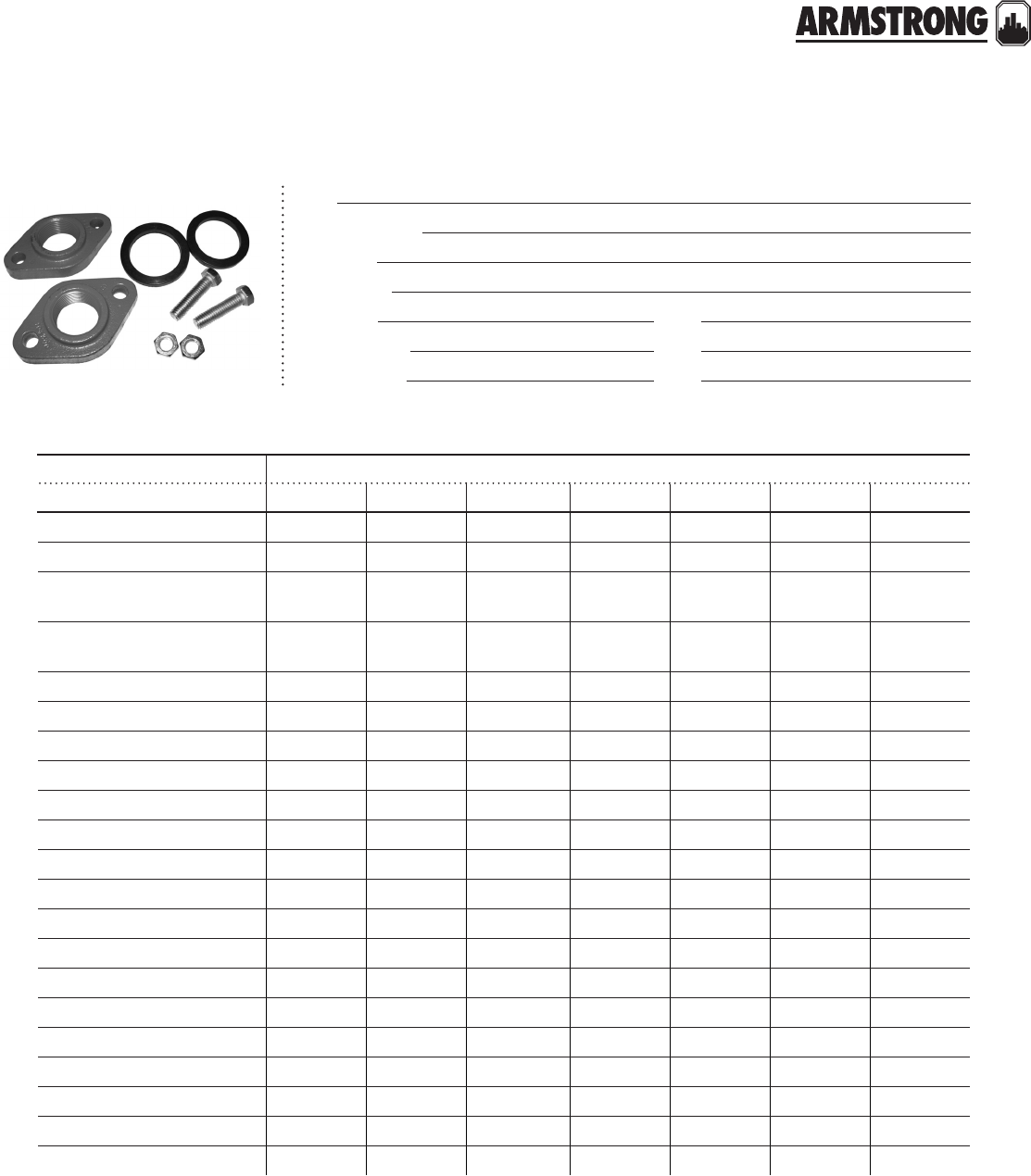
FLANGE KITS
|
PARTS INFORMATION
101
|
HYDRONIC SOLUTIONS CATALOG
Job:
Representative:
Engineer:
Contractor:
Order no: Date:
Submitted by: Date:
Approved by: Date:
cast iron flanges kits
cast iron pipe size and part number (for single flanges/flange kits)
model 0.75" 1.0" 1.25" 1.5" 2.0" 2.5" 3.0"
Astro 20 / 30 / 50 / 70 816013-111 816012-111 816011-111 816009-111
Astro 230/250CI/CI-R 816013-111 816012-111 816011-111 816009-111
E7 / E8 / E9 / E12 / E12-TE /
E14 / E14-TE / E15 / E17 816013-211 816012-211 816011-211 816009-211
E10 / E11 / E13 / E19 / E21 /
E22 / E23 / E24 806073-111 804300-111 804301-111
E16 806074-111
E28 / E29 805188-111
E30 (2") / E33 (2") 806074-111
E30 (3") / E33 (3") 805188-111
H-32 BF n/a n/a n/a
H-41 BF n/a
H-51 BF 816012-211
H-52 BF 816011-211
H-53 BF 816009-111
H-54 BF 806074-111
H-63 BF / H-64 BF / H-65 BF 804301-111
H-66 BF / H-67 BF / H-68 BF 806074-111
S-25 BF 816013-111 816012-111 816011-111 816009-111
S-35 BF n/a
S-45 BF n/a n/a
S-46 BF / S-55 BF / S-57 BF n/a
S-69 BF n/a
(A hardware kit is included in each flange kit.)
back to
contents
<
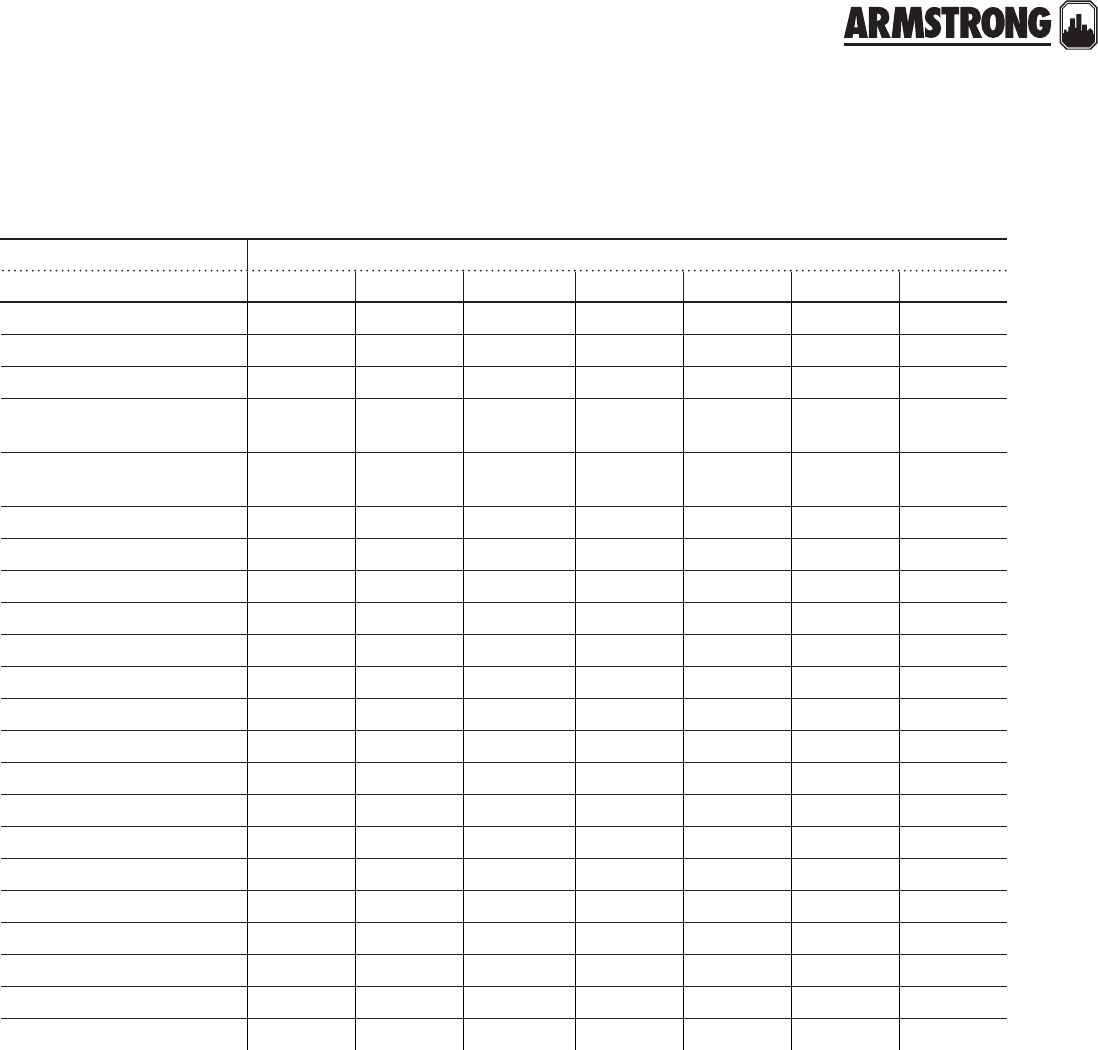
FLANGE KITS
|
PARTS INFORMATION
102
|
HYDRONIC SOLUTIONS CATALOG
lead free bronze flanges*
bronze pipe size and part number (for single flanges/flange kits)
model 0.75" 1.0" 1.25" 1.5" 2.0" 2.5" 3.0"
Astro 20B / 30B / 50B / 70B 816013-841 816012-841 816011-841 816009-841
Astro 230SS/250SS/280/286 816013-841 816012-841 816011-841 816009-841
Astro 290 806073-841 804300-841 804301-841
E7B / E8B / E9B / E12B / E14B /
E12B-TE / E14B-TE / E15B / E17B 816013-941 816012-941 816011-941 816009-941
E10B / E11B / E13B / E19B / E21B
/ E22B / E23B / E24B 806073-841 804300-841 804301-841
E16B 806074-841
E28B / E29B 805188-841
E30B (2") / E33B (2") 806074-841
E30B (3") / E33B (3") 805188-841
H-32 AB n/a n/a n/a
H-41 AB n/a
H-51 AB 816012-941
H-52 AB 816011-941
H-53 AB 816009-841
H-54 AB 806074-841
H-63 AB / H-64 AB / H-65 AB 804301-841
H-66 AB / H-67 AB / H-68 AB 806074-841
S-25 AB 816013-841 816012-841 816011-841 816009-841
S-35 AB n/a
S-45 AB n/a n/a
S-46 AB / S-55 AB / S-57 AB n/a
S-69 AB n/a
(A hardware kit is included in each flange kit.)
* Complies with section 116875 of the California Health and Safety Code & Vermont Act 193 (Lead content of all wetted surfaces 0.25% or less).

FLANGE KITS
|
PARTS INFORMATION
103
|
HYDRONIC SOLUTIONS CATALOG
union fitting sets (contain two (2) half unions and gaskets
model part number connection weight
Astro 20/25BU
810120-220 1.25" npsm × 0.5" Sweat
2 (0.91)
810120-222 1.25" npsm × 0.75" Sweat
810120-224 1.25" npsm × 0.5" fnpt
Astro 220SSU/225SSU
810120-320 Lead free bronze*
1.25" npsm × 0.5" Sweat
810120-322 Lead free bronze*
1.25" npsm × 0.75" Sweat
810120-324 Lead free bronze*
1.25" npsm × 0.5" fnpt
All dimensions are in inches (mm) and weights are in lbs (kgs).
*Certified <0.25 weighted average percent lead and Complies with California Health and Safety Code Section 116875 (commonly known as AB1953).
104
|
HYDRONIC SOLUTIONS CATALOG
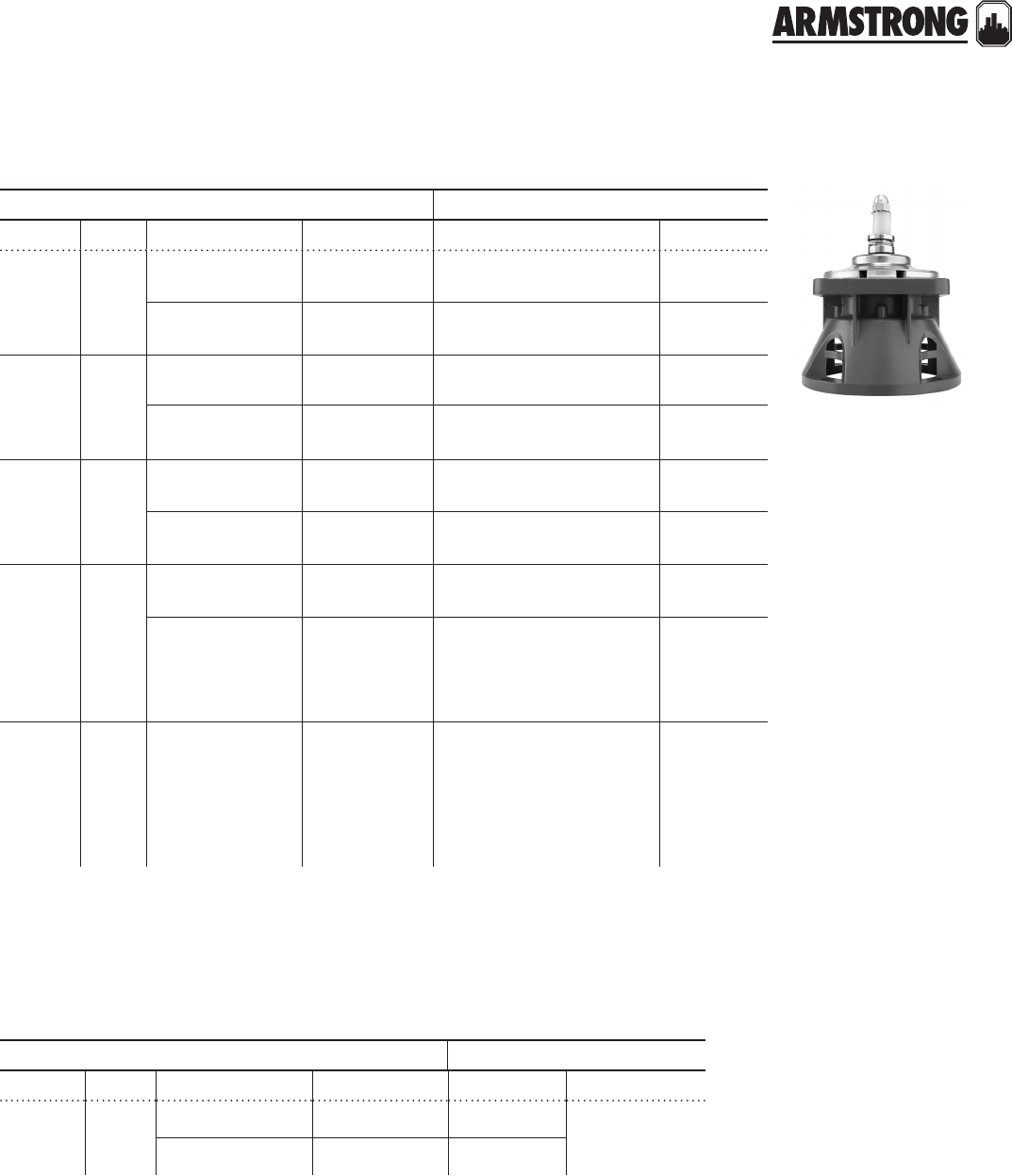
105
|
HYDRONIC SOLUTIONS CATALOG
SEAL BEARING ASSEMBLIES
WITH SEAL KIT ONLY
|
PARTS COMPARISON
armstrong b&g equivalent
model size part # description model part #
S-35
H-32
2
1, 1¼,
1½
816549-091†Sleeve design 2 (Manufactured prior to
7/76; Date Code GT)
189165LF/
189166LF
816549MF-091 Maintanence
free design
HV (Manufactured prior to
4/76; Date Code DT n/a
S-35
For B&G
Pumps
Only
2
1, 1¼,
1½
816023-001†Sleeve design 2 (Manufactured 7/76 or
after; Date Code GT)
189120-29,
189131
816023MF-001 Maintanence
free design
HV (Manufactured 4/76 or
after; Date Code DT) n/a
S-45
S-45
S-46
H-41
2½
3
3
1
816027-002†Sleeve design 2½
LD3189105LF
816027MF-002 Maintanence
free design
HD3
1 PR n/a
S-55
S-57
3
3816032-000†Sleeve design PD-35
PD-37
186863LF
186864LF
H-51
H-52
H-53
H-54
1
1¼
1½
2
816032MF-000 Maintanence
free design
60-1 (Old), 60-11 (New)
60-2 (Old)
60-3 (Old), 60-13 (New)
60-4 (Old), 60-14 (New)
n/a
For B&G
Pumps
Only
—
816133-000*
816134-000*
BF
AB PD-39
60-5 to 60-10 (Old),
60-15 to 60-21 (New)
185232LF
185232LF
185234LF
185234LF
185260LF
185262LF
* Use the B&G Impeller (with pressure balance holes) with these Bearing Assemblies. These Bearing Assemblies include the
following coverplates and are supplied with the seal kit and body gasket.
cover plates for b&g pumps sba
armstrong b&g equivalent
model size part # description model part #
For B&G
Pumps
Only
—
816347-011 BF —
816347-041 AB —
back to
contents
<
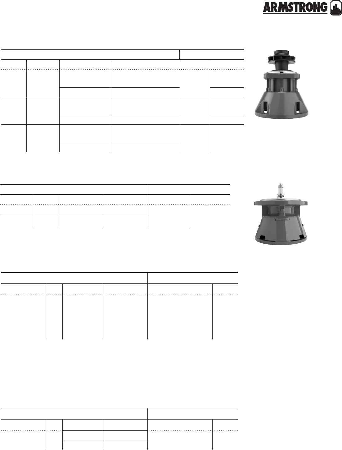
106
|
HYDRONIC SOLUTIONS CATALOG
armstrong b&g equivalent
model size part # description model part #
S-25 ¾, 1, 1¼,
1½
810119-001†Sleeve Design 75 to
100
118844LF/
189134LF
810119MF-001 Maintenance Free Design n/a
S-35 2810119-003†Sleeve New
Style HV
189165LF/
189166LF
810119MF-003 Maintenance Free Design n/a
H-32 1, 1¼, 1½ 810119-003†Sleeve Any 2"
NFI
189165LF/
189166LF
810119MF-003 Maintenance Free Design n/a
armstrong b&g equivalent
model size part # description model part #
S-69
H-63 to H-65
H-66 to H-68
3
1½
2
816366-041 STD, BF, AB
PD-39
60-5 to 60-7 (Old),
60-15 to 60-17 (New)
60-8 to 60-10 (Old),
60-18 to 60-21 (New)
—
bearing assemblies without seal and cover plate
cover plates for b&g pumps sba
bearing assemblies with seal and nfi impeller
The following coverplates are used with Bearing Assemblies 816366-041 and 816366-071 and do not
normally require replacement when Armstrong Bearing Assembly is changed or replaced. For a complete
Armstrong Seal Bearing Assembly (including coverplate, seal and body gasket), use p/n’s 816861-011 bf or
816861-841 ab.
† As of 07/01/94, a Stainless Steel faceplate is standard. For all iron applications, please contact the factory.
armstrong b&g equivalent
model size part # description model part #
S-69 3" 816861-011 STD BF No equivalent No equivalent
H63-H65 1½" 816861-841 AB
bearing assemblies with mechanical seal kit & cover plate
armstrong b&g equivalent
model size part # description model part #
For B&G
Pumps Only —816346-011 CI — —
816346-841 BR
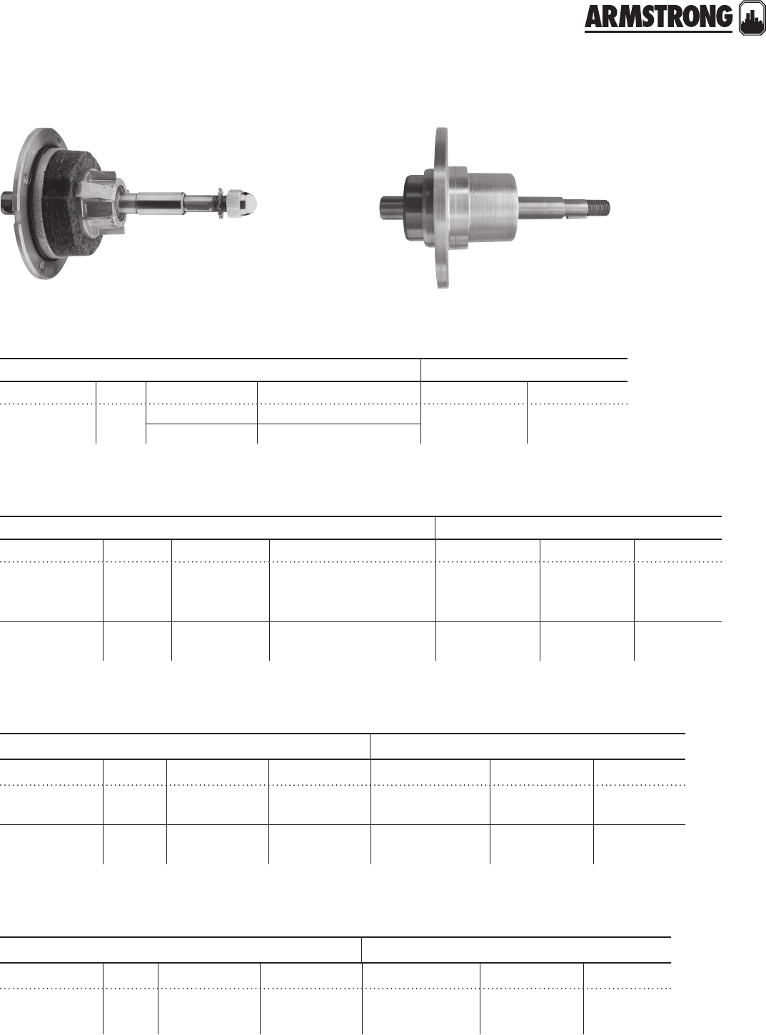
107
|
HYDRONIC SOLUTIONS CATALOG
SEAL BEARING MODULES
& ACCESSORIES
|
PARTS COMPARISON
shaft and bearing module
shaft and sleeve assemblies*
shaft keys*
bearing & cap assembly*
armstrong b&g equivalent
model size part # description model part #
S-25 to S-57,
H-32 to H-54 ½816999-041* Module - Sleeve design 75 to PD37,
HV to 60-14 No equivalent
816999MF-041 Module - MF design
armstrong b&g equivalent
model size part # description (sleeve) model old part # new part #
S-25 to S-57
H-32 to H-54 API only 816997-041 Copper 75 to PD37,
HV to 60-14
No equivalent
No equivalent 189035
S-69,
H-63 to H-68 —816354-041 Copper PD39,
60-15 to 60-21
No equivalent
No equivalent —
armstrong b&g equivalent
model size part # description model old part # new part #
S-25 to S-57,
H-32 to H-54 —974507-400 #2 Woodru 75 to PD37,
HV to 60-14 P-4138 P04940
S-69,
H-63 to H-68 —974508-100
974515-100
#3 Woodru
#9 Woodru
PD39,
60-15 to 60-21
PW1-3138
HP-606
P51760
H32550
armstrong b&g equivalent
model size part # description model old part # new part #
S-69,
H-63 to H-68 —874112-000 Bearing & Cap
Assembly
PD39,
60-15 to 60-21 No equivalent —
*Only available for sleeve design sbas.
fig. Bearing module- Sleeve design fig. Bearing module- mf design
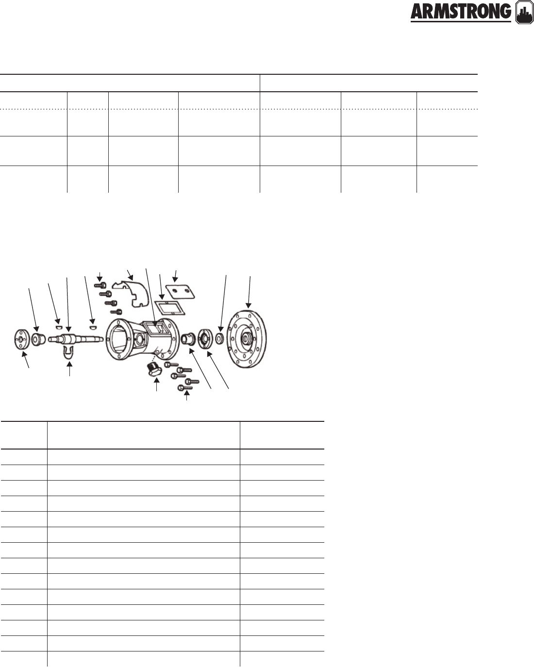
108
|
HYDRONIC SOLUTIONS CATALOG
armstrong b&g equivalent
model size part # description model old part # new part #
S-25 to S-46,
H-32, H-41 — 806993-000 Wool 75 to 3HD,
HV, 1 PR P4-4130 118395
S-55, S-57,
H-51 to H-54 — 812138-000 Wool 60-1 to 60-40,
PD35, PD37 PW4-4130 118624
S-69,
H-63 to H-68 — 816565-000 Wool 60-15 to 60-20,
PD39 No equivalent —
oilwicks
armstrong series 6 sba
(standard construction is bronze fitted)
for models
s69, h63-h68, 1060
21
1
1
1
1
1
1
1
8
6
7
49
44
4
rebuild kit for series 6 sba
Contains items 4, 6, 7, 8, and 9 above 816366-000
plus seal kit, oil, and body gasket.
item
number part description part number
1 Bearing bracket 816342-011
4Bearing cap assembly 874112-000
1 Coupler guard 116114-000
7Coupler key (woodru #9)974515-100
2 Coverplate (steel) 816346-041
1 Coverplate capscrews E/af-18 µ O911119-106
8Impeller key (woodru #3)974508-100
1 Oil level window 116904-001
9Oil slinger 116369-000
1 Oil well cover assy. c/w gasket 816362-000
1 Res. mtd. mtr. Capscrews W-16 µ X (4 req'd) 911121-106
6Shaft & sleeve assembly 816354-041
6Shaft & sleeve assy. (s/s shaft) 816354-071
1 Water slinger 116368-000

109
|
HYDRONIC SOLUTIONS CATALOG
COUPLER ASSEMBLIES
PARTS COMPARISON
counter clockwise rotation
armstrong b&g equivalent
model part # description model part #
S-25,
S-34, S-35,
H-32, H-41
806026-001†½ × ½
75 to 150,
1½, 2,
HV, PR
118705
189110, 118712
S-45, S-46 806168-001†½ × ½ 2½, LD3, HD3 118723
clockwise rotation
S-55, S-57
810120-006††
806137-001*
806140-001
½ × X
½ × X
½ × ¾
PD35, PD37
118709
118709
118708
H-51, H-52 810120-003††
807436-000*
½ × ½
½ × ½
60-1, 60-2 (Old),
60 -11 (New) 118473
H-53, H-54 810120-006††
806137-000*
½ × X
½ × X
60-3, 60-4 (Old),
60-13, 60-14 (New)
118709
118709
S-69,
H-63 to
H-68
810120-008††
812734-000*
816665-000*
X × ½
X × ½
X × X
PD39,
60-5 to 60-10 (Old),
60-15 to 60-21 (New)
186410
186410
118476, P77265
armstrong b&g equivalent
model part # description model part #
For B&G
Pumps Only
810120-004
810120-005
75 to 150, 2, HV,
PR, 1, 1¼, 1½, 2
118706
118707
† 4-Spring type coupler.
†† 4-Spring type coupling. For use on b&g circulators only.
coupler/mounting ring kit
armstrong
model size part # description part #
48 Frame Marathon motors A/ab, T, ¼, L hp 810120-050 —118223 (API P/N
810120-000)
118227 (API P/N
810120-001)
118228 (API P/N
810120-002)
56 Frame 1 Phase & 3 Phase
Marathon motors ½-1 hp 874055-000 —
56 Frame marathon ½, ¾ hp 874055-001 —
1 Phase Double
capacitor motors only — — —
motor mounting rings (resilient motors)
*Flexible spacer type coupling.
back to
contents
<
110
|
HYDRONIC SOLUTIONS CATALOG
111
|
HYDRONIC SOLUTIONS CATALOG
MOTORS
|
PARTS COMPARISON
armstrong b&g equivalent
model size part # description
(volts)
model old part # new
part #
S-25 A/ab hp 805316-010 115 CCW 70-150 P-115Z-3
P2Z-4 111034
S-35, H-32,
H-41 &
1050 1B,
1.25B and
1.5B
T hp 817025- 001 115 CCW
1½, 2,
HV,
PR
P-115Z-4
P4Z- 4
111036,
111031
For B&G Only T hp 817025-005 115 CCW -111061
S-45 ¼ hp 817025-007 115 CCW 2½,
LD3
P-115Z-10
P1Z-10 111040
S-46 L hp 817025-013 115 CCW HD3 P-115Z-12
P107- 6Z-496 111042
H-51 ¼ hp 816141-001 115 CW 60-11
PDH-115Z-10
PWH-314-
6Z-1296
169035
H-52 L hp 816141-002 115 CW 60-2
PDH1530Z-12
PWH-937-
6Z-1296
169038
H-53, H-63,
S-55 ½ hp 811757-001*†115/230 CW
60-13,
60-15,
PD35
PDH1530Z-14
PWH-929-
6Z-1296
111044
H-54, H-64,
H-66, S-57,
1050 1.5B &
2B and 1060
1.5D & 2D
¾ hp 811757-002*†115/230 CW
60-14,
60-16,
60-18,
PD37
PDH1530Z-16
PWH-925-
6Z-1296
111047
H-65, H-67,
S-69, 1060
1.5D & 2D
1 hp
1½ hp
811757-007†
816678-062**
115/230 CW
115/230 CW
60-17,
60-19,
PD39
60 2A
PDH1530Z-18
PD-2635Z-1296 111050
169005
mounted motors – 1750 rpm – single phase – 60 cycle
back to
contents
<
112
|
HYDRONIC SOLUTIONS CATALOG
MOTORS
|
PARTS COMPARISON
armstrong b&g equivalent
model size part # description
(volts)
model old part # new part #
H-53, H-63,
S-55 ½ hp 831011-083**
811757-020*†208/230/460 60-13, 60-15,
PD35
PDH82040Z-14
PWH-931- 6Z-1296 111046
H-54, H-64,
H-66, S-57 ¾ hp 831012-083**
811757-024*†208/230/460 60-14, 60-16,
60-18, PD37
PDH82040Z-16
P922-6PDZ-1296 111049
H-65, H-67,
S-69 1 hp 816676-069**
811757-028 208/230/460 60-17, 60-19,
PD39
PDH82040Z-18
PD2628Z-1296
169089
111051
169090
H-68 1½ hp 816678-069** 208/230/460 60-20 PDH82040Z-20
PWH-26 41Z-1296
169091
111052
169092
1000 2 hp 816681-069 208/230/460 60-21 —169094
armstrong b&g equivalent
model size part # description model old part # new part #
S-25 to S-57,
H-32 to H-54 —816001-000* —75 to PD37,
HV to 60-14 P4Z-4115 118697
mounted motors – 1750 rpm – three phase – 60 cycle
rear bearings
Notes:
† Resilient Mounted Motors.
* When replacing b&g motors, also replace coupler with Armstrong
806137-000 for the 5 series pumps and 816665-000 or the 6 series pumps.
** Rigid mount ball bearing motor can be supplied in lieu of the Resilient mount motor.
113
|
HYDRONIC SOLUTIONS CATALOG
SEAL KITS
|
PARTS COMPARISON
armstrong b&g equivalent
model size part # description model old part # new part #
S-25 to S-35, S-46
H-32 to H-41
S-55 to S-57 & H-51
to H-54 & all 1050s
½"
½"
816706-021
816706-023
SS with Buna
SS with Viton
75 to PD37,
HV to 60-14
#6 Kit
No equivalent
118681
186681
For B&G Pumps Only ¾" 810120-009 —PD38-40,
60A BF or AB 186499
S-69,
H-63 to H-68
¾"
¾"
816707-001
816707-003
Buna
Viton
PD39,
60-15 to 60-20
No equivalent
No equivalent —
E (old) ¼" 880200-877
E.2 G/af"880202-677 SS with Viton
back to
contents
<
114
|
HYDRONIC SOLUTIONS CATALOG
IMPELLERS
|
PARTS COMPARISON
armstrong b&g equivalent
model size part # description model dia. part #
S-25
2¾"
2¾"
2¾"
812961-011
812961-111
812961-041
ST
NFI
BR
100
2¾"
2¾"
2¾"
118840
189132LF
118431LF
S-35
3W"
3W"
3W"
816322-011
816322-041
816322-111
ST
BR
NFI
2
118668
P07792
189128LF
H-32
3W"
3W"
3W"
3W"
3W"
3W"
816322-011
816322-041
816322-111
ST
BR
NFI
HV No equivalent
816556-011
816556-041
816556-111
ST
BR
NFI
2, HV 3W"
3W"
118668LF
P07792
n/a
S-45
3Y"
3Y"
3Y"
816305-028
816305-058
816305-328
ST
BR
NFI
2½,
LD-3
3Y"
3Y"
118676
118440LF
S-46
4¼"
4¼"
4¼"
816305-025
816305-055
816305-325
ST
BR
NFI
HD-3 4¼"
4¼"
118675
118439LF
n/a
S-55
4¾"
4¾"
4¾"
816304-021
816304-051
816304-321
ST
BR
NFI
PD35 4¾"
4¾"
118630
118627
n/a
S-57
5¼"
5¼"
5¼"
816304- 017
816304-047
816304-317
ST
BR
NFI
PD37
5¼"
5¼"
118630
118627LF
n/a
S-69 5Y"
5Y"
816308-012
816308-042
ST
BR PD39 118452
118453LF
H-41
4¼"
4¼"
4¼"
816301-025
816301-055
816301-325
ST
BR
NFI
1 PR
4¼"
4¼"
118830
118612LF
n/a
H-51
5"
5"
5"
816302-019
816302-049
816302-319
ST
BR
NFI
60-11
5¼"
5¼"
n/a
186359 &
18630LF
n/a
H-52
5¼"
5¼"
5¼"
816302-017
816302-047
816302-317
ST
BR
NFI
60-2 5¼"
5¼"
n/a
186359LF
n/a
back to
contents
<
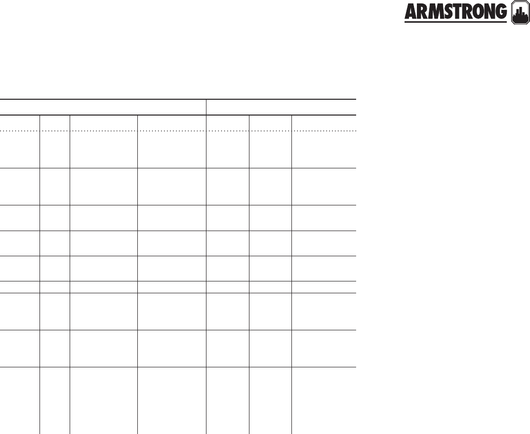
115
|
HYDRONIC SOLUTIONS CATALOG
IMPELLERS
|
PARTS COMPARISON
armstrong b&g equivalent
model size part # description model dia. new part #
H-53
5¼"
5¼"
5¼"
816303-017
816303-047
816303-317
ST
BR
NFI
60-13 5¼"
5¼"
P61010
186368
H-54
5¼"
5¼"
5¼"
816304- 017
816304-047
816304-317
ST
BR
NFI
60-14 5¼"
5¼"
118629
118626
H-63 5¾"
5¾"
174058-021
874058-051
CI
BR 60-15 5¼" —
H-64 6½"
6½"
174058-015
874058-045
CI
BR 60-16 — —
H-65 7"
7"
174058-011
174058-041
CI
BR 60-17 — —
H-66 5X" 816393-052 BR 60-18 — —
H-67 6¼"
6¼"
816393-047
816393-
017ST
BR 60-19 — —
H-68 6 ¾"
6¾"
816393-043
816393-
013ST
BR 60-20 — —
For
B&G
Pumps
Only
7"
7"
6"
816309-041
816310-041
816311-041
BR
BR
BR
60
1-½A
60 2A
PD-38,
39, 40
Various
Various
Various
P57445
P57450
118453
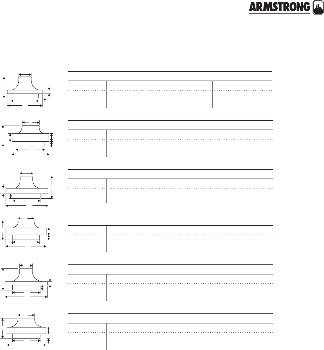
116
|
HYDRONIC SOLUTIONS CATALOG
IMPELLERS
|
PARTS COMPARISON
armstrong b&g equivalent
model part # model part #
S-46 816305-025 Steel
816305-055 Brass HD-3 118675 Steel
118439 Brass
armstrong b&g equivalent
model part # model part #
H-53 816303-047 Brass 60-13, 1 ½AA 186368
armstrong b&g equivalent
model part # model part #
S-57
H-54
816304-017 Steel
816304-047 Brass
PD 37
60 -14, 2AA
118629 Steel
118626 Brass
armstrong b&g equivalent
model part # model part #
H-52 816302-047 Brass 60-11, 1AA, 1
NAA 186359
armstrong b&g equivalent
model part # model part #
S-55 816304-021 Steel
816304-051 Brass PD35 118630 Steel
118627 Brass
4¼
3W
2½1
2
½
1
5N
4D/af
3W
2
X
X
K
Y
2
3W
K
5N
2W
2E/af
5N
7A/a
f
3W
1H/af
K
2
2W
3W
K
Y
3W
armstrong b&g equivalent
model part # model part #
H-41 816301-025 Steel
816301-055 Brass PR 118830
118612 Brass
4¼
2W
G/af
K
1I/af
3W
dimensions
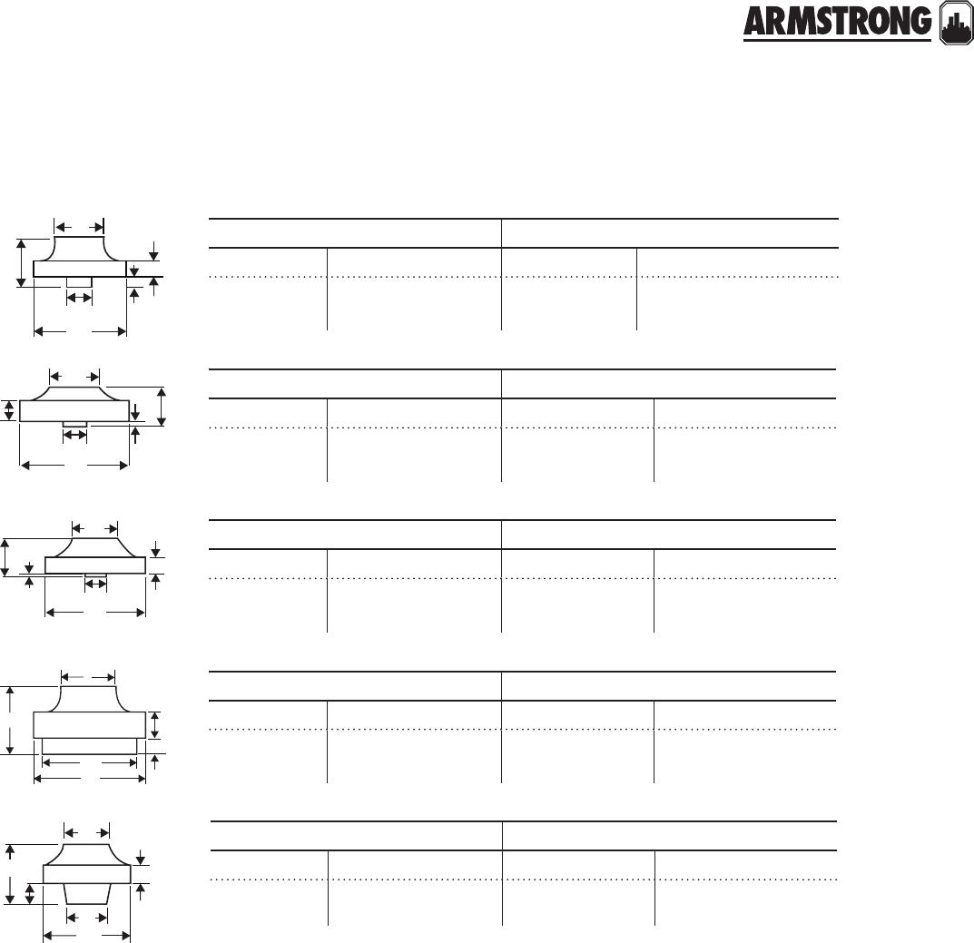
117
|
HYDRONIC SOLUTIONS CATALOG
IMPELLERS
|
PARTS COMPARISON
armstrong b&g equivalent
model part # model part #
S-25 812961-011 Steel
812961-841 Brass Series 100 118431 Brass
118840 (Discontinued)
armstrong b&g equivalent
model part # model part #
816556-011 Steel
816556-841 Brass HV & 2" (old stlye) 118668 Steel
118436 Brass
armstrong b&g equivalent
model part # model part #
806331-111 NFI 1" & 1½" (old stlye) 118665-6 Steel
118434-5 Brass
armstrong b&g equivalent
model part # model part #
S-45 2½"
or 3"
816305-028 Steel
816305-058 Brass 2½" & LD-3 118676 Steel
118440 Brass
1
W
1½
2O
Y
G/
af
W
1G/af
3C/h
1A/d
G/h
E/
h
C/cb
3V
1A/d I/a
f
A/af G/h
1
K
2
½
2
3Y
3W
½
1
armstrong b&g equivalent
model part # model part #
S-25 812961-111 NFI Series 100 189132
1
W
1K
1NX
½
2O
dimensions
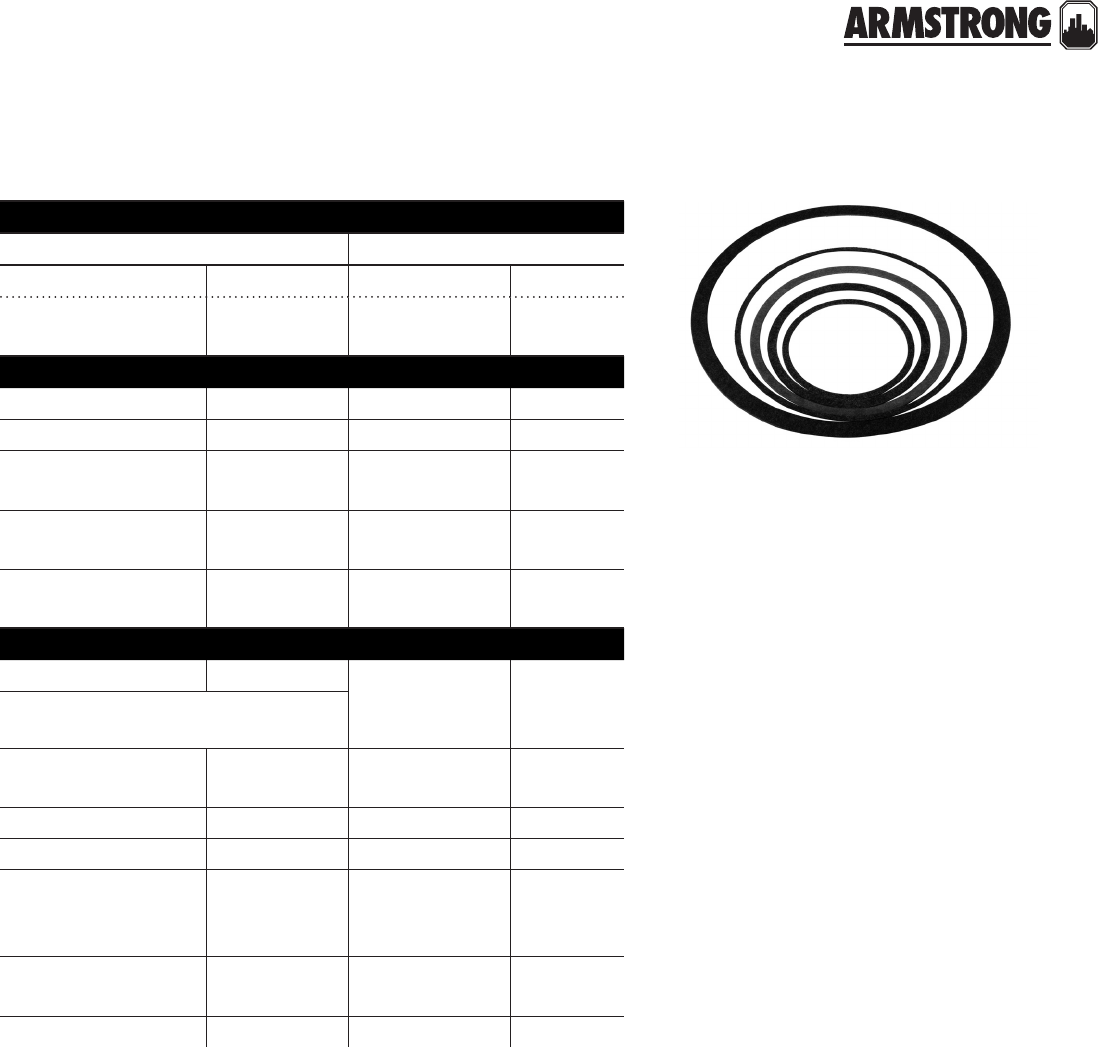
118
|
HYDRONIC SOLUTIONS CATALOG
GASKETS
|
PARTS COMPARISON
bearing gaskets
armstrong b&g equivalent
model part # model part #
S-25 to S-57,
H-51 to H-54 103408-000 75 to PD-37,
60-11 to 60-14 P01830
body gaskets
S-25 104442-000 75 to 150 P04080
S-35, H-32 106049-000 1½, 2, HV P04890
S-45, S-46, H-41 106050-000 2½, 3LD, 3HD,
1 PR P05800
S-55, S-57,
H-51 to H-54 & 1050 106158-000 PD35, PD37,
60-11 to 60-14 P57410
S-69, H-63 to H-68
& 1060 106592-000 PD39, 60-15 to
60-21 P57700
flange gaskets
S-25 816653-000
75 to 150 118368
(Alternative wide gasket for s-25 after
serial 6703)
H-41, H-51, H-52,
H-53 805176-000 1 PR, 60-11,
60-12, 60-13 118368
S-34, H-32 804034-000 1½, HV 118373
S-35 805209-000 2118065
S-45, S-46,
S-55, S-57, S-69 805201-000
2½, LD3, HD3,
PD35, PD37,
PD39
118129
H-54, H-66 to H-68 816117-000 60-14, 60-18 to
60-21 118378
H-63 to H-65 804034-000 60-15 to 60-17 118373
back to
contents
<
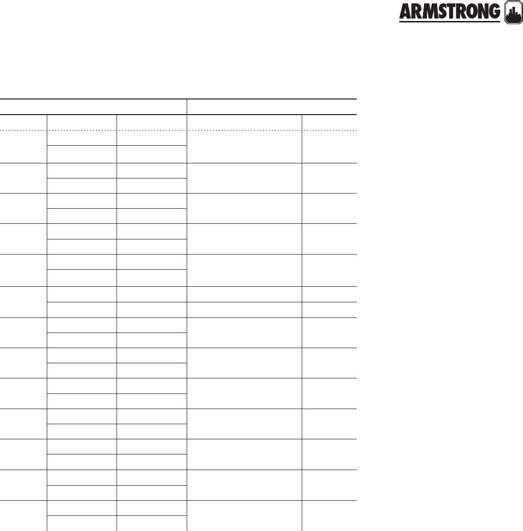
119
|
HYDRONIC SOLUTIONS CATALOG
PUMP BODIES
|
PARTS COMPARISON
armstrong b&g equivalent
model part # description model part #
S-25 805482-011 CI 75 to 150 118339
118413LF
105482-841 LF Bronze
H-32 816402-011 CI
—
116402-841 LF Bronze
S-35 816327-011 CI 2
116327-841 LF Bronze
S-45
S-46
805484-011 CI 2½, LD3, HD3 118644
P07610
105484-841 LF Bronze
H-41 811240-011 CI 1PR 118637
P07570
111240-841 LF Bronze
S-55
S-57
804133-011 CI PD35, PD37 118449
104133-841 LF Bronze P09290
S-69 816339-011 CI PD39
116339-841 LF Bronze
H-51 816337-011 CI 60-1 (Old), 60-11 (New) 186384
186385
116337-841 LF Bronze
H-52 816337-011 CI 60-2 (Old) 186386
116337-841 LF Bronze
H-53 816337-011 CI 60-3 (Old), 60-13 (New) 186389
P57130
116337-841 LF Bronze
H-54 816338-011 CI 60-4 (Old), 60-14 (New) 186392
P57200
116338-841 LF Bronze
H-63 to
H-65
816397-011 CI 60-5 to 60-7 (Old),
60-15 to 60-17 (New) —
116397-841 LF Bronze
H-66 to
H-68
816174-011 CI 60-8 to 60-10 (Old),
60-15 to 60-21 (New) —
116174-841 LF Bronze
back to
contents
<
120
|
HYDRONIC SOLUTIONS CATALOG
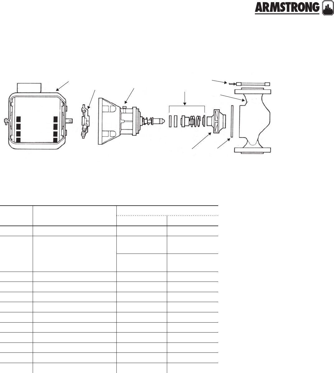
121
|
HYDRONIC SOLUTIONS CATALOG
CIRCULATORS
|
PARTS LOOK UP
784
2
1
29
28
15
model number
itt/b&g 75 to 150 armstrong s-25 std/bf/ab
item
number part description part number
armstrong b&g
7A/ab hp motor 805316-010 111034
2 Universal seal bearing assembly
(w/noryl impeller)
810119-001
(Sleeve design)
118844LF/
189034LF
810119-001
(MF design ) n/a
2Bronze impeller 812961-041 118431LF
2Steel impeller 812961-011 118840LF
2Noryl impeller 812961-111 189132LF
8Coupler 806026-001 189110/118705
2 Body gasket 104442-000 P04080
4Flange gasket 805176-000* 118368
4Flange gasket kit 816653-000 Armstrong only
1 Seal kit 816706-021 118681
1Bronze body (Lead Free) 105482-841 118413LF
1Cast iron body 805482-011 118339
*Gasket kit contains 2 ¬ 116653-000 gaskets and 2 ¬ 105176-000 gaskets.
For flanges: See flanges cross reference sheet.
back to
contents
<back to
contents
<
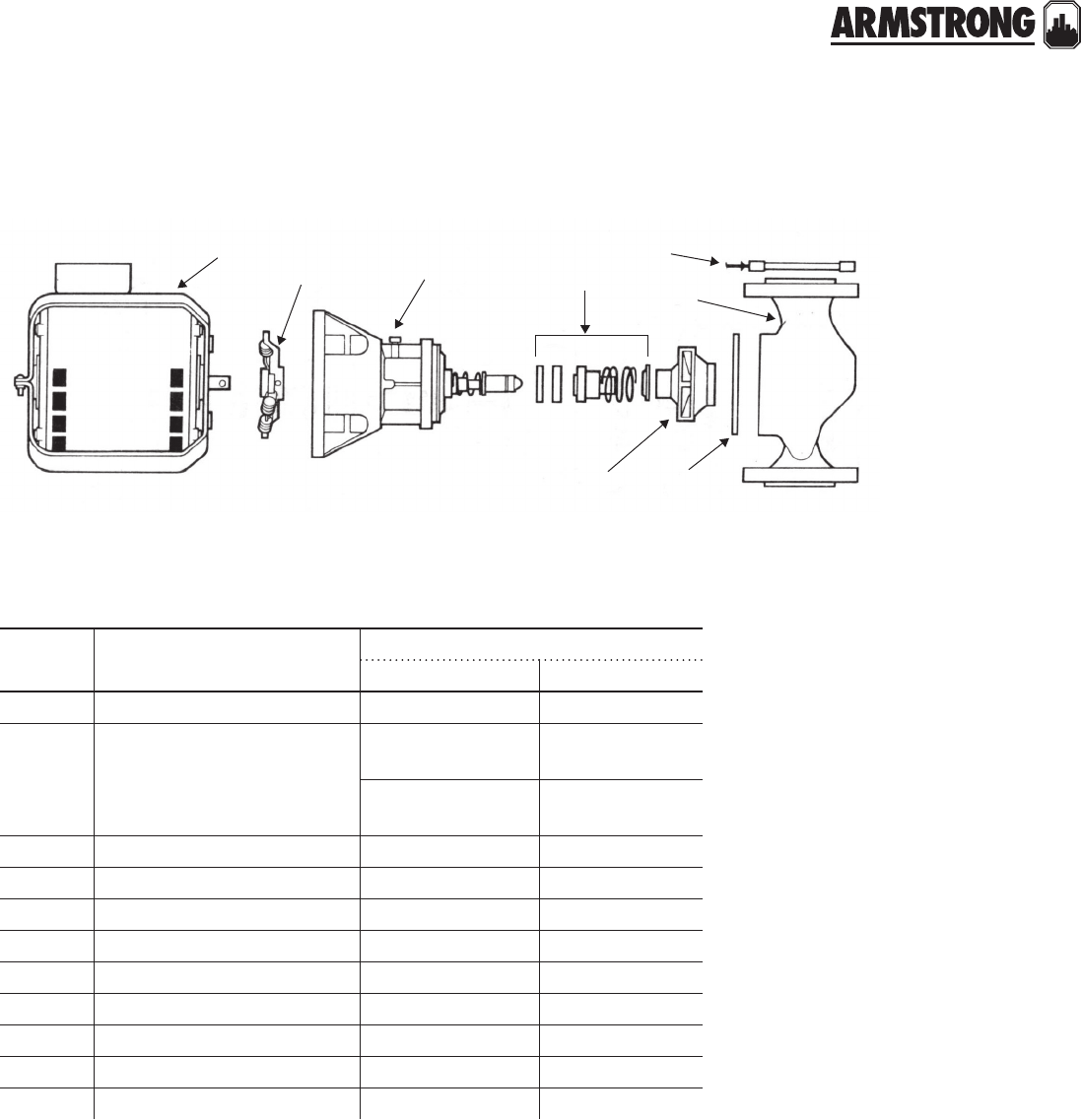
122
|
HYDRONIC SOLUTIONS CATALOG
CIRCULATORS
|
PARTS LOOK UP
itt/b&g 2"
(mftd. prior to G/gf, date code gt)
armstrong s-35 bf/ab
item
number part description part number
armstrong b&g
7T hp motor 817025-001 111036, 111031
2 Universal seal bearing assembly
(w/noryl impeller)
810119-003
(Sleeve design)
189100
189103
810119MF-003
(MF design) n/a
2Bronze impeller 816556-041 P07792
2Steel impeller 816556-011 118668
8Coupler 806026-001 118705/189110
2 Body gasket 106049-000 P04890
4Flange gasket prior 1967 805209-000 118065
4Flange gasket new n/a n/a
1 Seal kit 816706-021 118681
1Bronze body (Lead Free) 116327-841 n/a
1Cast iron body 816327-011 n/a
For flanges: See flanges cross reference sheet.
784
2
1
29
28
15
back to
contents
<
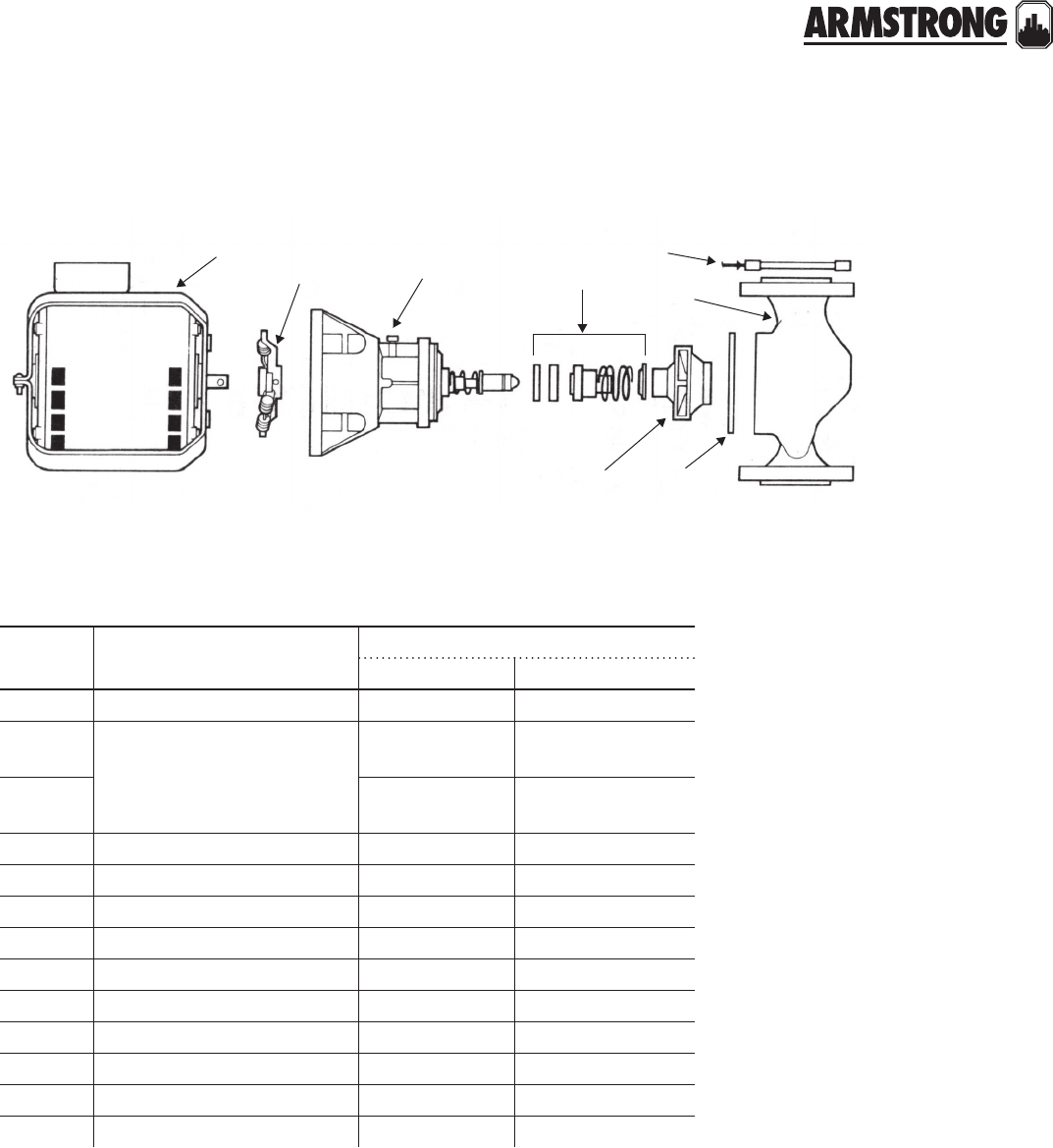
123
|
HYDRONIC SOLUTIONS CATALOG
CIRCULATORS
|
PARTS LOOK UP
itt/b&g hv
(mftd. prior to D/gf, date code dt)
armstrong h-32 bf/ab
item
number part description part number
armstrong b&g
7T hp motor 817025-001 111036, 111031
2 Universal seal bearing assembly
(w/noryl impeller)
810119-003
(Sleeve design)
189165LF/
189166LF
2 810119MF-003
(MF design) n/a
2Bronze impeller 816322-041 P07792
2Steel impeller 816322-011 118668
2Noryl impeller 816322-111 n/a
8Coupler 806026-001 118705/189110
2 Body gasket 106049-000 P04890
4Flange gasket prior 1967 804034-000 118373
4Flange gasket new n/a n/a
1 Seal kit 816706-021 118681
1Bronze body (Lead Free) 116402-841 118642
1Cast iron body 816402-011 118641
For flanges: See flanges cross reference sheet.
784
2
1
29
28
15
back to
contents
<
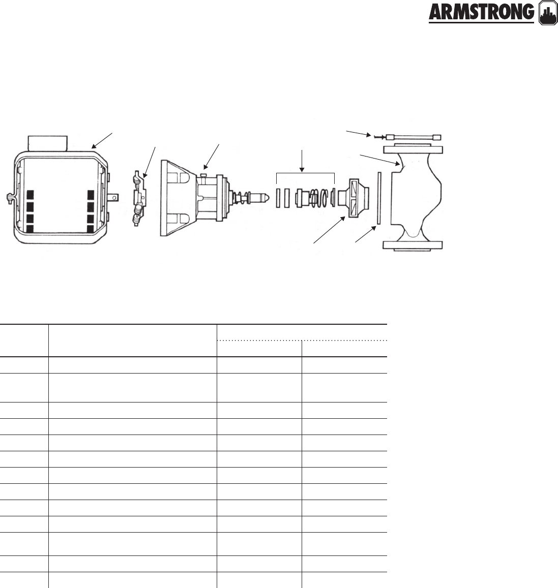
124
|
HYDRONIC SOLUTIONS CATALOG
CIRCULATORS
|
PARTS LOOK UP
784
2
1
29
28
15
itt/b&g 2"
(mftd. G/gf or after, date code dt)
armstrong s-35
for b&g pumps only
item
number part description part number
armstrong b&g
7T hp motor 817025-005 111061
2 Seal bearing assembly (Sleeve design) 816023-001 189165LF/
189166LF
2 Seal bearing assembly (MF design) 816023MF-001 n/a
2Bronze impeller n/a 189128
2Steel impeller n/a P07792
2Noryl impeller n/a n/a
8Coupler 806026-001 118705/189110
2 Body gasket 106049-000 P04890
4Flange gasket 805209-000 118065
4Flange gasket new n/a n/a
1 Seal kit 816706-021 118681
1Bronze body n/a 189127
1Cast iron body n/a 189126
back to
contents
<

125
|
HYDRONIC SOLUTIONS CATALOG
CIRCULATORS
|
PARTS LOOK UP
784
2
1
29
28
15
itt/b&g 2½" armstrong s-45 bf 2½" flange
item
number part description part number
armstrong b&g
7N hp motor 817025-007 111040
2 Seal bearing assembly (Sleeve design) 816027-002 189105LF
2 Seal bearing assembly (MF design) 816027MF-002 n/a
2Bronze impeller 816305-058 118440LF
2Steel impeller 816305-028 118676
2Noryl impeller 816305-328 n/a
8Coupler 806168-001 118723
2 Body gasket 106050-000 P05800
4Flange gasket 805201-000 118129
4Flange gasket new n/a n/a
1 Seal kit 816706-021 118681
1Bronze body (Lead Free) 105484-841 P07610
1Cast iron body 805484-011 118644
back to
contents
<

126
|
HYDRONIC SOLUTIONS CATALOG
CIRCULATORS
|
PARTS LOOK UP
784
2
1
29
28
15
itt/b&g ld3 armstrong s-45 bf 3" flange
item
number part description part number
armstrong b&g
7N hp motor 817025-007 111040
2 Seal bearing assembly (Sleeve design) 816027-002 189105LF
2 Seal bearing assembly (MF design) 816027MF-002 n/a
2Bronze impeller 816305-058 118440LF
2Steel impeller 816305-028 118676
2Noryl impeller 816305-328 n/a
8Coupler 806168-001 118723
2 Body gasket 106050-000 P05800
4Flange gasket 805201-000 118129
4Flange gasket new n/a n/a
1 Seal kit 816706-021 118681
1Bronze body (Lead Free) 105484-841 P07610
1Cast iron body 805484-011 118644
For flanges: See flanges cross reference sheet.
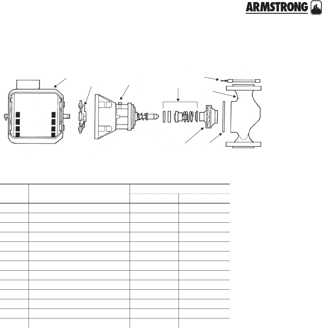
127
|
HYDRONIC SOLUTIONS CATALOG
CIRCULATORS
|
PARTS LOOK UP
784
2
1
29
28
15
itt/b&g hd3 armstrong s-46
item
number part description part number
armstrong b&g
7L hp motor 817025-013 111042
2 Seal bearing assembly (Sleeve design) 816027-002 189105LF
2 Seal bearing assembly (MF design) 816027MF-002 n/a
2Bronze impeller 816305-055 118439LF
2Steel impeller 816305-025 118675
2Noryl impeller 816305-328 n/a
8Coupler 806168-001 118723
2 Body gasket 106050-000 P05800
4Flange gasket 805201-000 118129
4Flange gasket new n/a n/a
1 Seal kit 816706-021 118681
1Bronze body (Lead Free) 105484-841 P07610
1Cast iron body 805484-011 118644
back to
contents
<
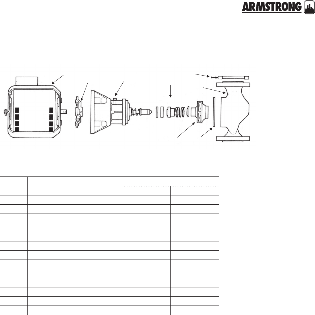
128
|
HYDRONIC SOLUTIONS CATALOG
CIRCULATORS
|
PARTS LOOK UP
784
2
1
29
28
15
itt/b&g 1 pr armstrong h-41 bf & ab
item
number part description part number
armstrong b&g
7T hp motor 817025-001 111036/111031
2 Seal bearing assembly (Sleeve design) 816027-002 189105LF
2 Seal bearing assembly (MF design) 816027MF-002 n/a
2Bronze impeller 816301-055 118612LF
2Steel impeller 816301-025 118830
2Noryl impeller 816301-325 n/a
8Coupler 806026-001 118705/189110
2 Body gasket 106050-000 P05800
4Flange gasket 805176-000 118368
4Flange gasket new n/a n/a
1 Seal kit 816706-021 118681
1Bronze body (Lead Free) 111240-841 P07570
1Cast iron body 811240-011 118637
back to
contents
<
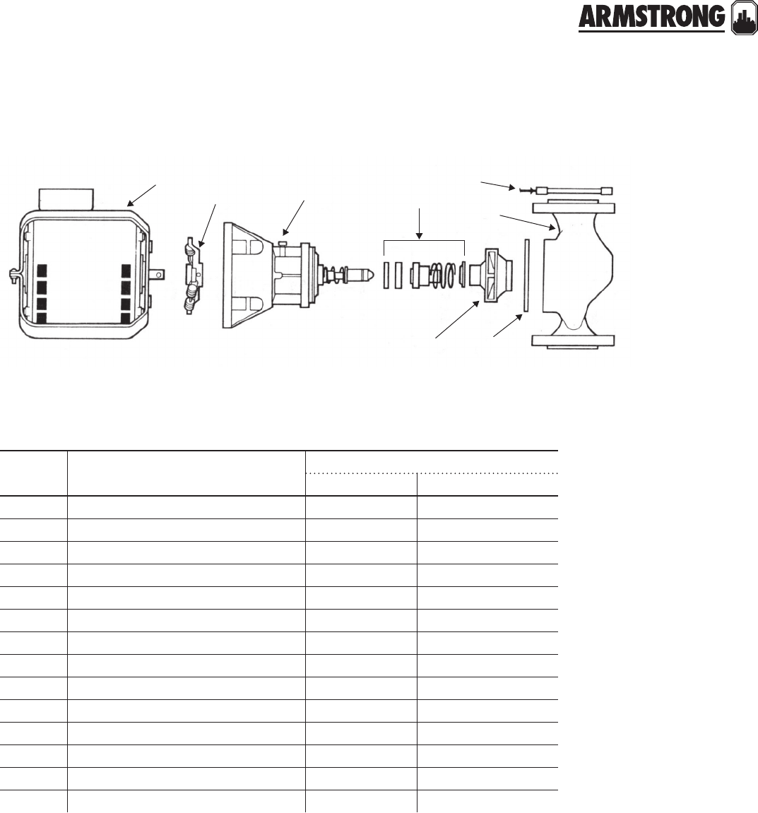
129
|
HYDRONIC SOLUTIONS CATALOG
CIRCULATORS
|
PARTS LOOK UP
784
2
1
29
28
15
itt/b&g pd-35 armstrong s-55
(standard construction is bronze fitted)
item
number part description part number
armstrong b&g
7K hp motor 1ph/60/115/230 811757-001 111044
7K hp motor 3ph/60/208/230/460 811757-020 111046
2 Seal bearing assembly (Sleeve design) 816032-000 186863LF/186864LF
2 Seal bearing assembly (MF design) 816032MF-000 n/a
2Bronze impeller 816304-051 118627
2Steel impeller 816304-021 118630
2Noryl impeller 816304-321 n/a
8Coupler K"µ X" 806137-000 118709
8Coupler K"µ ¾" 806140-000 118708
2 Body gasket 106158-000 P57410
4Flange gasket 805201-000 118129
1 Seal kit 816706-021 118681
1Bronze body (Lead Free) 104133-841 P09290
1Cast iron body 804133-011 118449
back to
contents
<
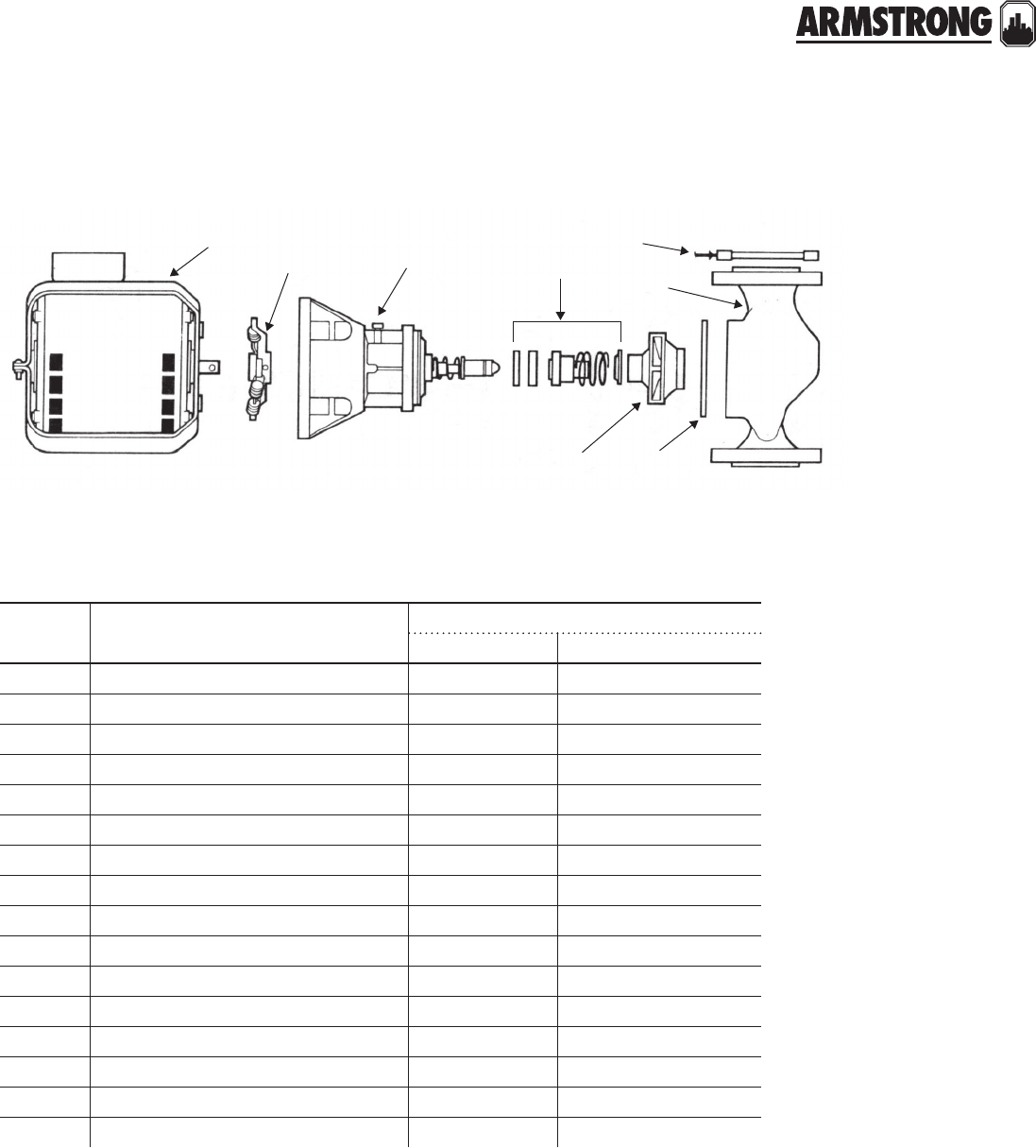
130
|
HYDRONIC SOLUTIONS CATALOG
CIRCULATORS
|
PARTS LOOK UP
784
2
1
29
28
15
itt/b&g pd-37 armstrong s-57
(standard construction is bronze fitted)
item
number part description part number
armstrong b&g
7¾ hp motor 1ph/60/115/230 811757-002 111047
7¾ hp motor 1ph/60/115/230 831010-062
7¾ hp motor 3ph/60/208/230/460 831012-083 111049
7¾ hp motor 3ph/60/575 811757-006
2 Seal bearing assembly (Sleeve design) 816032-000 186863LF/186864LF
2 Seal bearing assembly (MF design) 816032MF-000 n/a
2Bronze impeller 816304-047 118626
2Steel impeller 816304-027 118629
2Noryl impeller 816304-317 n/a
8Coupler K"µ X" 806137-000 118709
8Coupler K"µ ¾" 806140-000 118708
2 Body gasket 106158-000 P57410
4Flange gasket 805201-000 118129
1 Seal kit 816706-021 118681
1Bronze body (Lead Free) 104133-841 P09290
1Cast iron body 804133-011 118449
back to
contents
<

131
|
HYDRONIC SOLUTIONS CATALOG
CIRCULATORS
|
PARTS LOOK UP
784
2
1
29
28
15
itt/b&g 60-1 (old), 60-11 (new) armstrong h-51
(standard construction is bronze fitted)
item
number part description part number
armstrong b&g
7N hp motor 1ph/60/115/230 816141-001 111040
2 Seal bearing assembly (Sleeve design) 816032-000 186863LF/186864LF
2 Seal bearing assembly (MF design) 816032MF-000 n/a
2Bronze impeller 816302-049 186359/186360LF
2Steel impeller 816302-019 186441
2Noryl impeller 816302-319 n/a
8Coupler 807436-000 118473
2 Body gasket 106158-000 P57410
4Flange gasket 805176-000 118368
1 Seal kit 816706-021 118681
1Bronze body (Lead free) 116337-841 186385
1Cast iron body 816337-011 186384
back to
contents
<
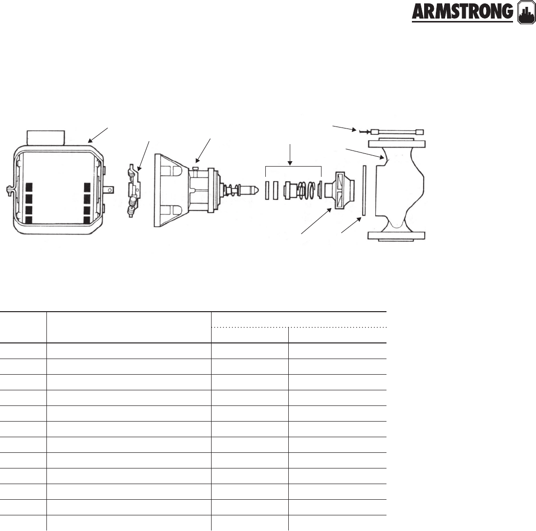
132
|
HYDRONIC SOLUTIONS CATALOG
CIRCULATORS
|
PARTS LOOK UP
784
2
1
29
28
15
itt/b&g 60-2 (old) armstrong h-52 bf single phase
(standard construction is bronze fitted)
item
number part description part number
armstrong b&g
7L hp motor 1ph/60/115/230 816141-002 169038
2 Seal bearing assembly (Sleeve design) 816032-000 186863LF/186864LF
2 Seal bearing assembly (MF design) 816032MF-000 n/a
2Bronze impeller 816302-047 186359
2Steel impeller 816302-017 186441
2Noryl impeller 816302-317 n/a
8Coupler 807436-000 118473
2 Body gasket 106158-000 P57410
4Flange gasket 805176-000 118368
1 Seal kit 816706-023 118681
1Bronze body (Lead Free) 116337-841 n/a
1Cast iron body 816337-011 186386
back to
contents
<
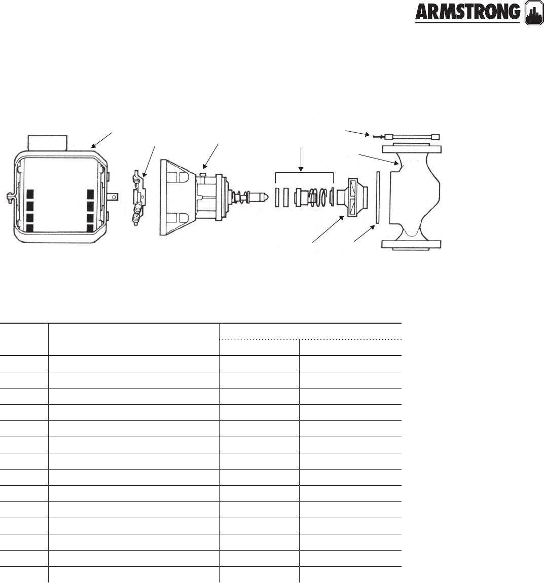
133
|
HYDRONIC SOLUTIONS CATALOG
CIRCULATORS
|
PARTS LOOK UP
784
2
1
29
28
15
itt/b&g 60-3 (old), 60-13 (new) armstrong h-53 bf & ab
(standard construction is bronze fitted)
item
number part description part number
armstrong b&g
7K hp motor 1ph/60/115/230 811757-001 111044
7K hp motor 3ph/60/208/230/460 831011-083 111046
7K hp motor 3ph/60/575 811757-004
2 Seal bearing assembly (Sleeve design) 816032-000 186863LF/186864LF
2 Seal bearing assembly (MF design) 816032MF-000 n/a
2Bronze impeller 816303-047 186368
2Steel impeller 816303-017 P61010
2Noryl impeller 816303-317 n/a
8Coupler K"µ X" 806137-000 118709
2 Body gasket 106158-000 P57410
4Flange gasket 805176-000 118368
1 Seal kit 816706-021 118681
1Bronze body (Lead Free) 116337-841 n/a
1Cast iron body 816337-011 186386
Note:
When replacing b&g with Armstrong equivalent for ½ and ¾ you must also change the coupler
b&g has ½" motor shaft
Armstrong has X" motor shaft
back to
contents
<
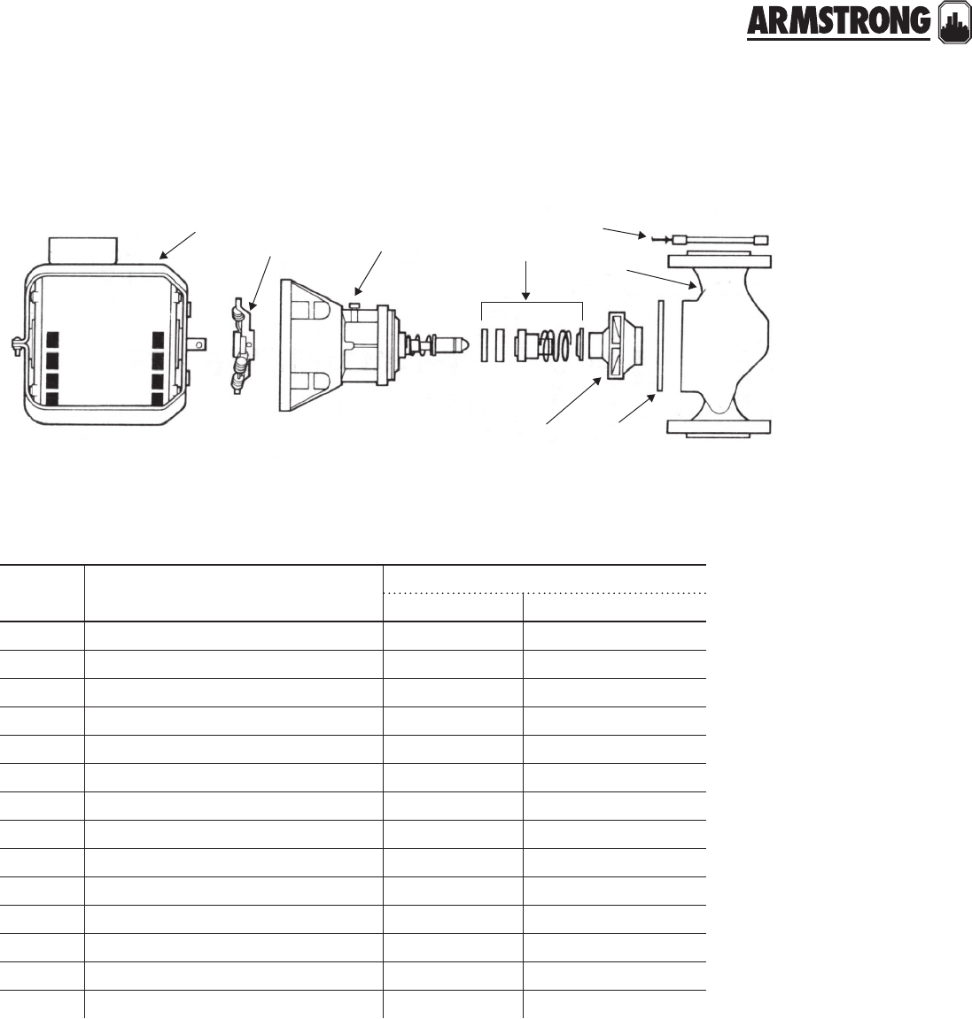
134
|
HYDRONIC SOLUTIONS CATALOG
CIRCULATORS
|
PARTS LOOK UP
itt/b&g 60-4 (old), 60-14 (new) armstrong h-54 bf & ab
(standard construction is bronze fitted)
item
number part description part number
armstrong b&g
7O hp motor 1ph/60/115/230 811757-002 111047
7O hp motor 3ph/60/208/230/460 831012-083 111049
7O hp motor 3ph/60/575 811757-006
2 Seal bearing assembly (Sleeve design) 816032-000 186863LF/186864LF
2 Seal bearing assembly (MF design) 816032MF-000 n/a
2Bronze impeller 816304-047 118626
2Steel impeller 816304-017 118629
2Noryl impeller 816304-317 n/a
8Coupler K"µ X" 806137-000 118709
2 Body gasket 106158-000 P57410
4Flange gasket 816117-000 118378
1 Seal kit 816706-021 118681
1Bronze body (Lead Free) 116338-841 P57200
1Cast iron body 816338-011 186392
784
2
1
29
28
15
back to
contents
<
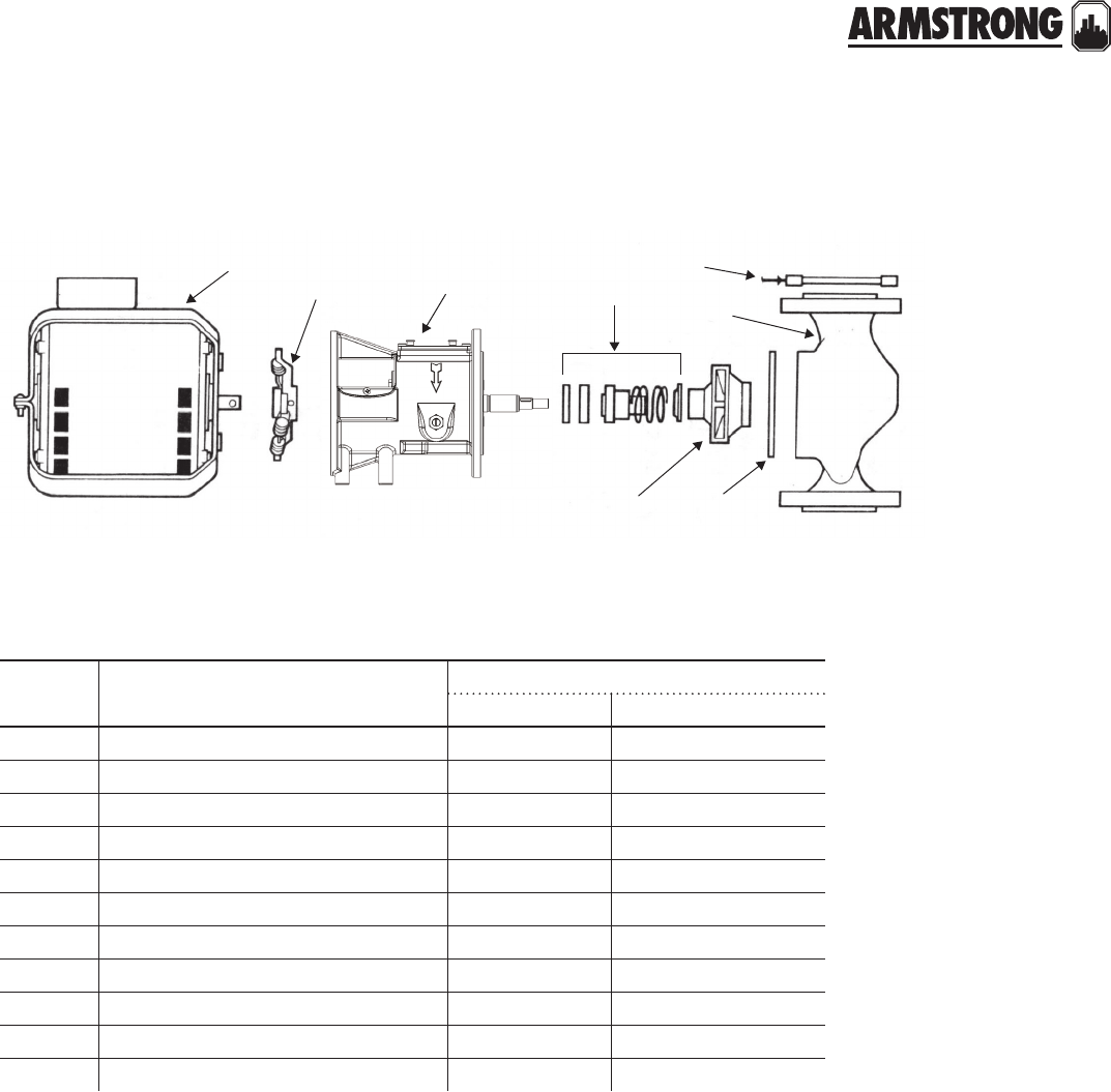
135
|
HYDRONIC SOLUTIONS CATALOG
CIRCULATORS
|
PARTS LOOK UP
itt/b&g pd-38, pd-40 armstrong s-69
(standard construction is bronze fitted)
item
number part description part number
armstrong b&g
71 hp motor 1ph/60/115/230 816676-062 169232
71 hp motor 3ph/60/208/230/460 816676-069 169233
71 hp motor 3ph/60/575 811757-009
2 Seal bearing assembly (Sleeve design) 816366-041 185260/185262
2Bronze impeller 816308-042 P08690
2Steel impeller 816308-012 P08709
8Coupler assembly/flexible X µ X816665-000 186004/186003
2 Body gasket 106592-000 118129
4Flange gasket 105201-000
1 Seal kit 816707-001 186433
1Bronze body 816339-011
784
2
1
29
28
15
back to
contents
<
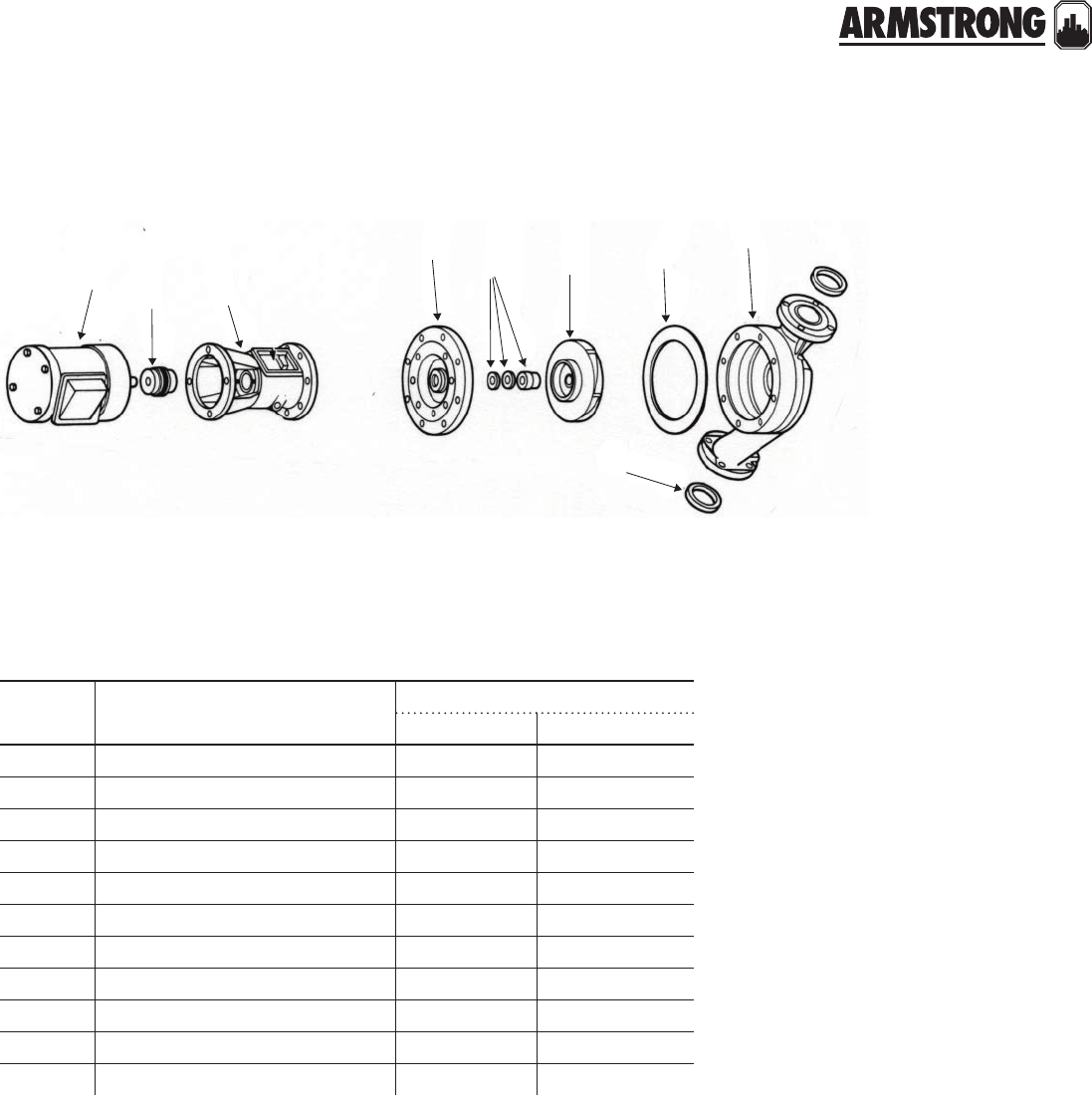
136
|
HYDRONIC SOLUTIONS CATALOG
CIRCULATORS
|
PARTS LOOK UP
itt/b&g pd-39
(mftd. prior to AJ/gg, date coded ku)
armstrong - no equivalent
item
number part description part number
armstrong b&g
71 hp motor 1ph/60/115/230 811757-007 111050
71 hp motor 3ph/60/208/230/460 811757-028 111051
2 Seal bearing assembly (std./b.f.) 816133-000** 185232
2 Seal bearing assembly (a.b.) 816134-000** 185234
2Bronze impeller 816311-041 118453
2Steel impeller n/a n/a
8Coupler X"µ K" 812734-000 186410
8Coupler X"µ X" 816665-000 118476/P77265
2 Body gasket 106592-000 P57700
4Flange gasket 805201-000 118129
1 Seal kit 810120-009 186499
78
4
21
29
29 28
15
**note: Use the B&G Impeller (with pressure balance holes) with these Bearing Assemblies. These Bearing Assemblies include the following Cover Plates and are supplied
with Part Number 817607-001 Seal Kit and Body Gasket:
#20 for std. & b.f. 816347-011
#20 for a.b. 816347-041
model number

137
|
HYDRONIC SOLUTIONS CATALOG
CIRCULATORS
|
PARTS LOOK UP
itt/b&g pd-39
(mftd. prior to AJ/gg or after , date coded ku)
armstrong - no equivalent
item
number part description part number
armstrong b&g
71 hp motor 1ph/60/115/230 811757-007 111050
71 hp motor 3ph/60/208/230/460 811757-028 111051
2 Seal bearing assembly (std./b.f.) 816133-000** 185260
2 Seal bearing assembly (a.b.) 816134-000** 185262
2Bronze impeller 816311-041 118453
2Steel impeller n/a n/a
8Coupler X"µ K" 810120-008 186410
8Coupler X"µ X" 816665-000 118476/P77265
2 Body gasket 106592-000 P57700
4Flange gasket 805201-000 118129
1 Seal kit 810120-009 186499
(standard construction is bronze fitted)
78
4
21
29
29 28
15
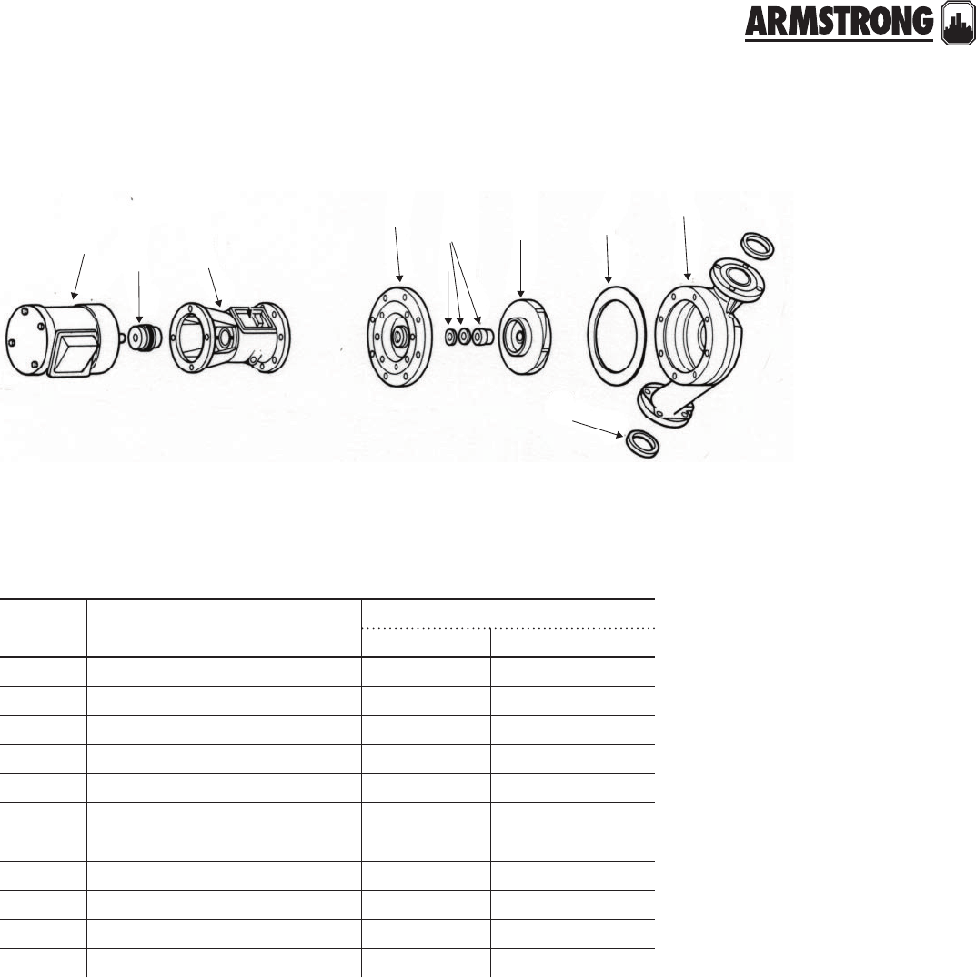
138
|
HYDRONIC SOLUTIONS CATALOG
CIRCULATORS
|
PARTS LOOK UP
itt/b&g 60-5 (old), 60-15 (new)
(mftd. prior to AJ/gg or after , date coded ku)
armstrong - no equivalent
item
number part description part number
armstrong b&g
7K hp motor 1ph/60/115/230 811757-001 111044
7K hp motor 3ph/60/208/230/460 811757-020 111046
2 Seal bearing assembly (std./b.f.) 816133-000** 185232
2 Seal bearing assembly (a.b.) 816134-000** 185234
2Bronze impeller 816309-041 P57445
2Steel impeller n/a n/a
8Coupler X"µ K" 810120-008 186410
8Coupler X"µ X" 816665-000 118476/P77265
2 Body gasket 106592-000 P57700
4Flange gasket 804034-000 118373
1 Seal kit 810120-009 186499
**note: Use the B&G Impeller (with pressure balance holes) with these Bearing Assemblies. These Bearing Assemblies include the following Cover Plates and are supplied
with Part Number 817607-001 Seal Kit and Body Gasket:
#20 for std. & b.f. 816347-011
#20 for a.b. 816347-041
(standard construction is bronze fitted)
78
4
21
29
29 28
15

139
|
HYDRONIC SOLUTIONS CATALOG
CIRCULATORS
|
PARTS LOOK UP
78
4
21
29
29 28
15
itt/b&g 60-6 (old), 60-16 (new)
(mftd. prior to AJ/gg , date coded ku)
armstrong - no equivalent
item
number part description part number
armstrong b&g
7O hp motor 1ph/60/115/230 811757-002 111047
7O hp motor 3ph/60/208/230/460 831012-083 111049
2 Seal bearing assembly (std./b.f.) 816133-000** 185232
2 Seal bearing assembly (a.b.) 816134-000** 185234
2Bronze impeller 816309-041 P57445
2Steel impeller n/a n/a
8Coupler X"µ K" 810120-008 186410
8Coupler X"µ X" 816665-000 118476/P77265
2 Body gasket 106592-000 P57700
4Flange gasket 804034-000 118373
1 Seal kit 810120-009 186499
(standard construction is bronze fitted)

140
|
HYDRONIC SOLUTIONS CATALOG
CIRCULATORS
|
PARTS LOOK UP
78
4
21
29
29 28
15
itt/b&g 60-9 (old), 60-19 (new)
(mftd. prior to AJ/gg , date coded ku)
armstrong - no equivalent
item
number part description part number
armstrong b&g
71 hp motor 1ph/60/115/230 811757-007 111050
71 hp motor 3ph/60/208/230/460 811757-028 111051
2 Seal bearing assembly (std./b.f.) 816133-000** 185232
2 Seal bearing assembly (a.b.) 816134-000** 185234
2Bronze impeller 816310-041 P57450
2Steel impeller n/a n/a
8Coupler X"µ K" 810120-008 186410
8Coupler X"µ X" 816665-000 118476/P77265
2 Body gasket 106592-000 P57700
4Flange gasket 816117-000 118378
1 Seal kit 810120-009 186499
**note: Use the B&G Impeller (with pressure balance holes) with these Bearing Assemblies. These Bearing Assemblies include the following Cover Plates and are supplied
with Part Number 817607-001 Seal Kit and Body Gasket:
#20 for std. & b.f. 816347-011
#20 for a.b. 816347-041
(standard construction is bronze fitted)

141
|
HYDRONIC SOLUTIONS CATALOG
CIRCULATORS
|
PARTS LOOK UP
78
4
21
29
29 28
15
itt/b&g 60-7 (old), 60-17 (new)
(mftd. prior to AJ/gg , date coded ku)
armstrong - no equivalent
item
number part description part number
armstrong b&g
71 hp motor 1ph/60/115/230 811757-007 111050
71 hp motor 3ph/60/208/230/460 811757-028 111051
2 Seal bearing assembly (std./b.f.) 816133-000** 185232
2 Seal bearing assembly (a.b.) 816134-000** 185234
2Bronze impeller 816309-041 P57445
2Steel impeller n/a n/a
8Coupler X"µ K" 810120-008 186410
8Coupler X"µ X" 816665-000 118476/P77265
2 Body gasket 106592-000 P57700
4Flange gasket 804034-000 118373
1 Seal kit 810120-009 186499
(standard construction is bronze fitted)
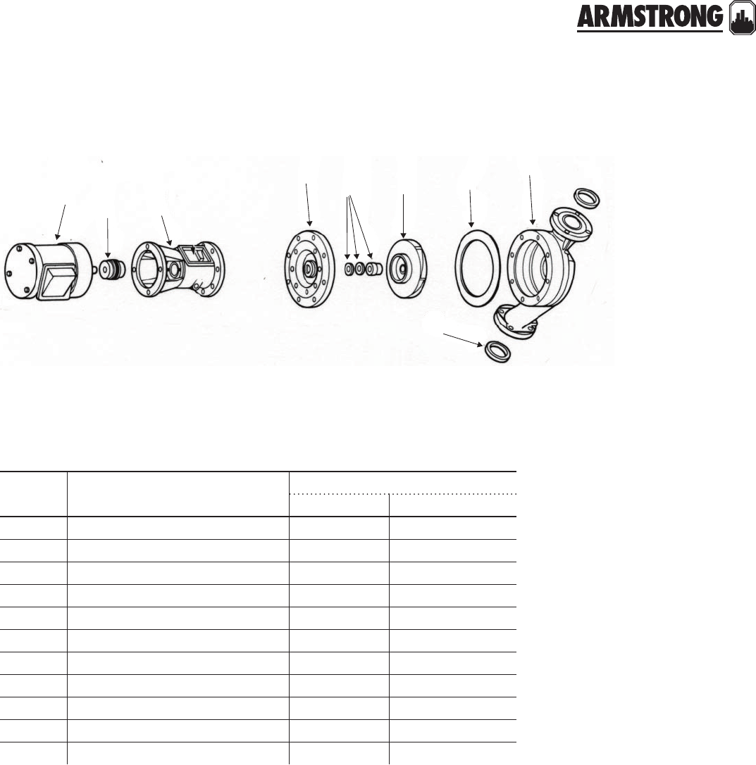
142
|
HYDRONIC SOLUTIONS CATALOG
CIRCULATORS
|
PARTS LOOK UP
78
4
21
29
29 28
15
itt/b&g 60-10 (old), 60-20 (new)
(mftd. prior to AJ/gg , date coded ku)
armstrong - no equivalent
item
number part description part number
armstrong b&g
71K hp motor 1ph/60/115/230 816678-062 169005
71K hp motor 3ph/60/208/230/460 816678-069 169091/169092
2 Seal bearing assembly (std./b.f.) 816133-000** 185232
2 Seal bearing assembly (a.b.) 816134-000** 185234
2Bronze impeller 816310-041 P57450
2Steel impeller n/a n/a
8Coupler X"µ K" 810120-008 186410
8Coupler X"µ X" 816665-000 118476/P77265
2 Body gasket 106592-000 P57700
4Flange gasket 804034-000 118373
1 Seal kit 810120-009 186499
**note: Use the B&G Impeller (with pressure balance holes) with these Bearing Assemblies. These Bearing Assemblies include the following Cover Plates and are supplied
with Part Number 817607-001 Seal Kit and Body Gasket:
#20 for std. & b.f. 816347-011
#20 for a.b. 816347-041
(standard construction is bronze fitted)

143
|
HYDRONIC SOLUTIONS CATALOG
CIRCULATORS
|
PARTS LOOK UP
itt/b&g 60-6 (old), 60-16 (new)
(mftd. prior to AJ/gg or after, date coded ku)
armstrong - no equivalent
item
number part description part number
armstrong b&g
7O hp motor 1ph/60/115/230 811757-002 111047
7O hp motor 3ph/60/208/230/460 831012-083 111049
2 Seal bearing assembly (std./b.f.) 816133-000** 185260
2 Seal bearing assembly (a.b.) 816134-000** 185262
2Bronze impeller 816309-041 P57445
2Steel impeller n/a n/a
8Coupler X"µ K" 810120-008 186410
8Coupler X"µ X" 816665-000 118476/P77265
2 Body gasket 106592-000 P57700
4Flange gasket 804034-000 118373
1 Seal kit 810120-009 186499
(standard construction is bronze fitted)
78
4
21
29
29 28
15

144
|
HYDRONIC SOLUTIONS CATALOG
CIRCULATORS
|
PARTS LOOK UP
itt/b&g 60-7 (old), 60-17 (new)
(mftd. prior to AJ/gg or after, date coded ku)
armstrong - no equivalent
item
number part description part number
armstrong b&g
71 hp motor 1ph/60/115/230 811757-007 111050
71 hp motor 3ph/60/208/230/460 811757-028 111051
2 Seal bearing assembly (std./b.f.) 816133-000** 185260
2 Seal bearing assembly (a.b.) 816134-000** 185262
2Bronze impeller 816309-041 P57445
2Steel impeller n/a n/a
8Coupler X"µ K" 810120-008 186410
8Coupler X"µ X" 816665-000 118476/P77265
2 Body gasket 106592-000 P57700
4Flange gasket 804034-000 118373
1 Seal kit 810120-009 186499
**note: Use the B&G Impeller (with pressure balance holes) with these Bearing Assemblies. These Bearing Assemblies include the following Cover Plates and are supplied
with Part Number 817607-001 Seal Kit and Body Gasket:
#20 for std. & b.f. 816347-011
#20 for a.b. 816347-041
(standard construction is bronze fitted)
78
4
21
29
29 28
15

145
|
HYDRONIC SOLUTIONS CATALOG
CIRCULATORS
|
PARTS LOOK UP
78
4
21
29
29 28
15
itt/b&g 60-9 (old), 60-19 (new)
(mftd. prior to AJ/gg or after, date coded ku)
armstrong - no equivalent
item
number part description part number
armstrong b&g
71 hp motor 1ph/60/115/230 811757-007 111050
71 hp motor 3ph/60/208/230/460 811757-028 111051
2 Seal bearing assembly (std./b.f.) 816133-000** 185260
2 Seal bearing assembly (a.b.) 816134-000** 185262
2Bronze impeller 816310-041 P57450
2Steel impeller n/a n/a
8Coupler X"µ K" 810120-008 186410
8Coupler X"µ X" 816665-000 118476/P77265
2 Body gasket 106592-000 P57700
4Flange gasket 816117-000 118378
1 Seal kit 810120-009 186499
(standard construction is bronze fitted)
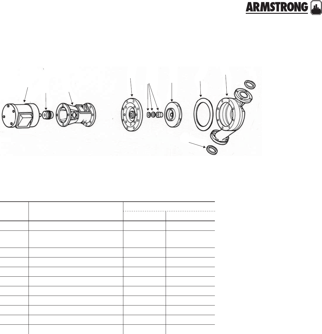
146
|
HYDRONIC SOLUTIONS CATALOG
CIRCULATORS
|
PARTS LOOK UP
78
4
21
29
29 28
15
itt/b&g 60-10 (old), 60-20 (new)
(mftd. prior to AJ/gg or after, date coded ku)
armstrong - no equivalent
item
number part description part number
armstrong b&g
71K hp motor 1ph/60/115/230 816678-062 169005
71K hp motor 3ph/60/208/230/460 816678-069 169091/169092
111052
2 Seal bearing assembly (std./b.f.) 816133-000** 185260
2 Seal bearing assembly (a.b.) 816134-000** 185262
2Bronze impeller 816310-041 P57450
2Steel impeller n/a n/a
8Coupler X"µ K" 810120-008 186410
8Coupler X"µ X" 816665-000 118476/P77265
2 Body gasket 106592-000 P57700
4Flange gasket 804034-000 118373
1 Seal kit 810120-009 186499
**note: Use the B&G Impeller (with pressure balance holes) with these Bearing Assemblies. These Bearing Assemblies include the following Cover Plates and are supplied
with Part Number 817607-001 Seal Kit and Body Gasket:
#20 for std. & b.f. 816347-011
#20 for a.b. 816347-041
(standard construction is bronze fitted)
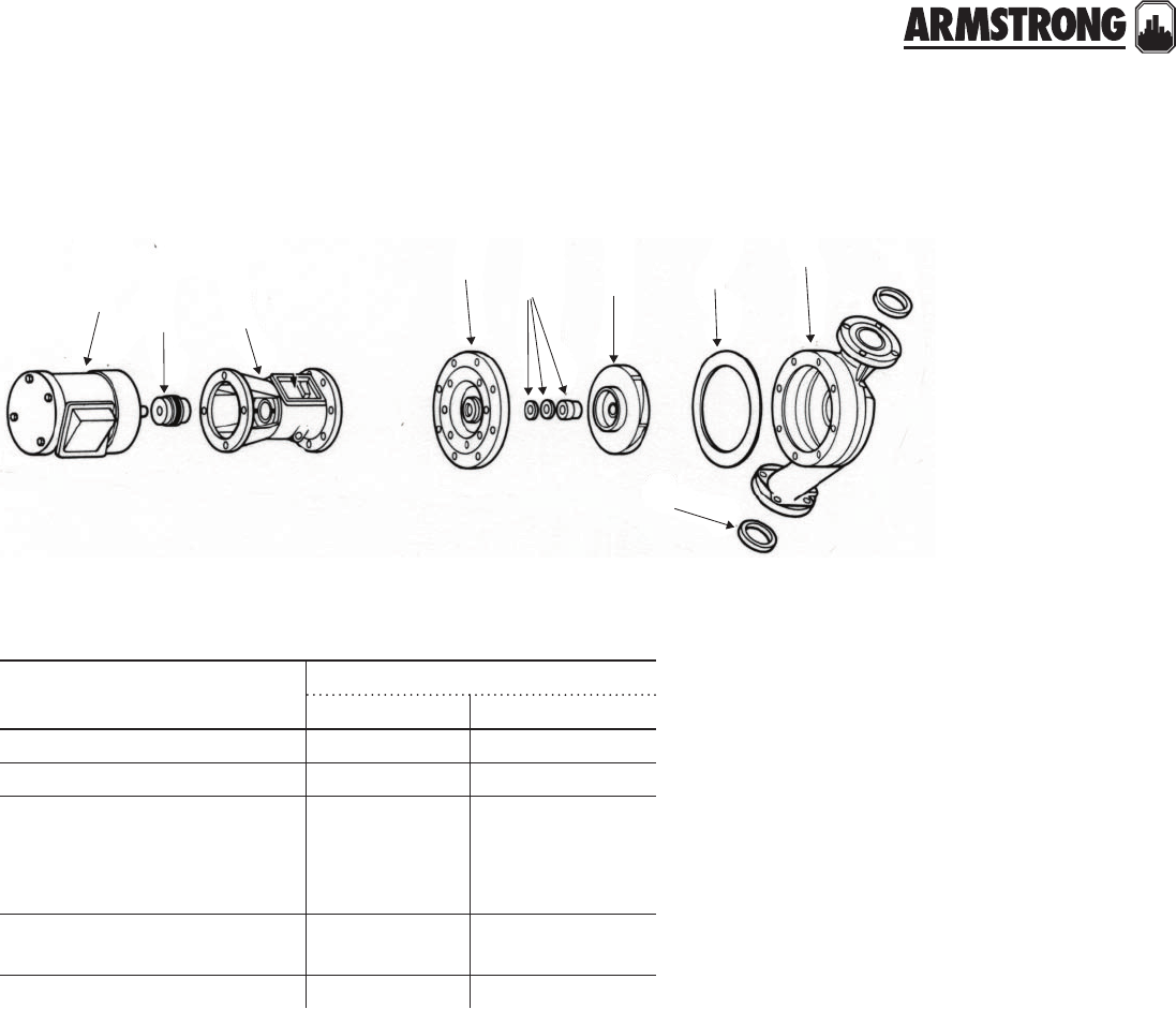
147
|
HYDRONIC SOLUTIONS CATALOG
CIRCULATORS
|
PARTS LOOK UP
for b&g pumps only
description part number
armstrong b&g
2" - sba 816023-001 189129-189120
2" - T hp motor 817025-005 111061
sba for pd-39,
60-5, 60-6, 60-7, 60-9 & 60-10
60-15, 60-16, 60-17, 60-19 & 60-20
816133-000***
185260 Std/BF
Old #pd26z-12351
185232 Std/BF
Old #pd25z-12351
Same as above 816134-000*** 185262 AB
185234 AB
hd3 - L hp motor 816025-013 111042
**note: Use the B&G Impeller (with pressure balance holes) with these bearing assemblies. These seal bearing assemblies include the 816366-041 bearing assembly,
816707-001 seal kit, and either the 816347-011 Std./B.F. cover plate of the 816347-041 A.B.
78
4
21
29
29 28
15
148
|
HYDRONIC SOLUTIONS CATALOG
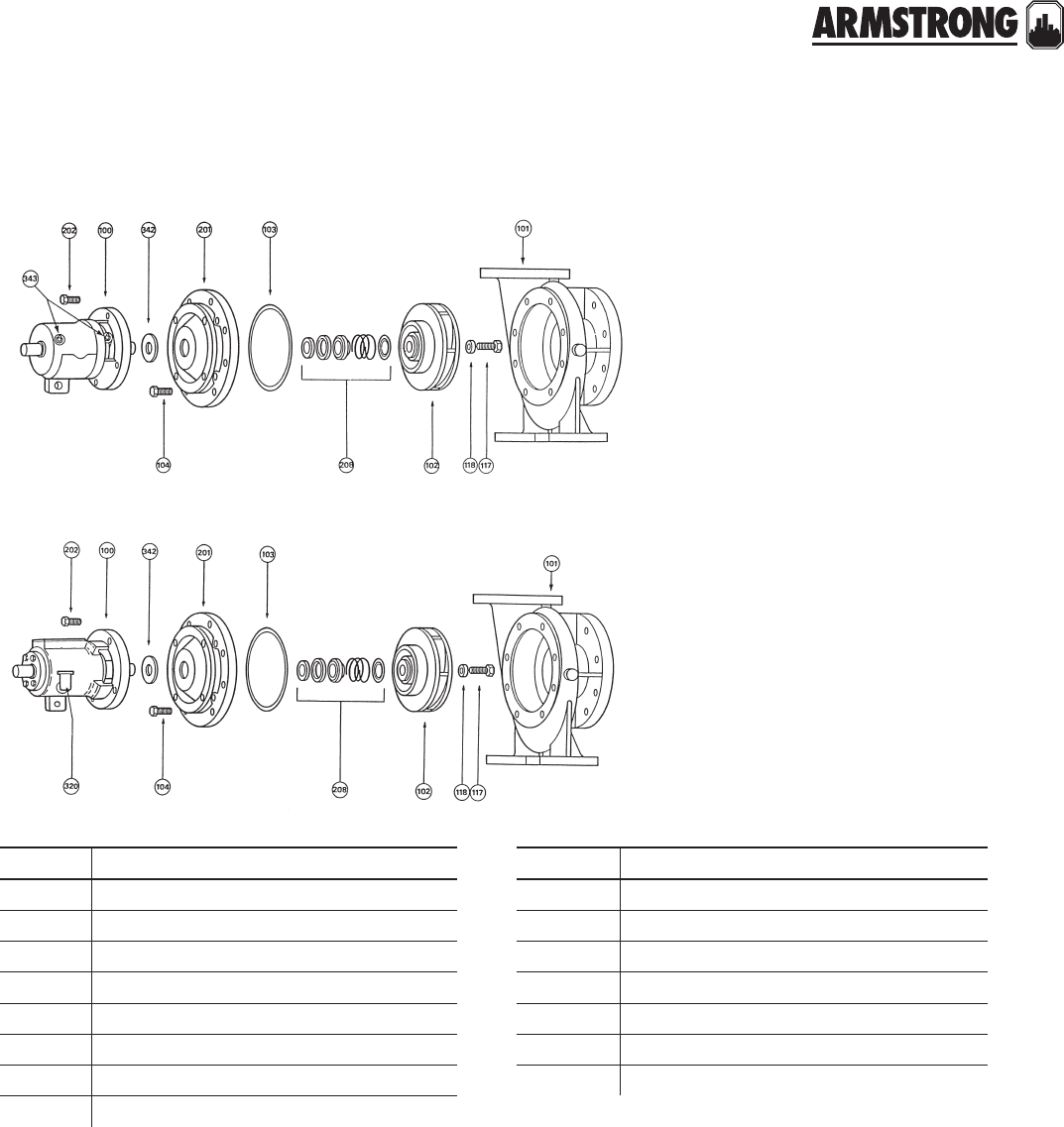
149
|
HYDRONIC SOLUTIONS CATALOG
4030 & 4020 BASE MOUNTED PUMPS
END SUCTION
|
PARTS CROSS REFERENCE
model 4030
model 4020
item description item description
100 Bearing frame assembly 202 Cover plate capscrew
101 Volute 208 Mechanical seal assembly
102 Impeller 320
103 Volute gasket 342 Water slinger
104 Volute capscrew 343
117 Impeller capscrew 401 Coupler selection table (wooden type)
118 Impeller washer 407 Coupler insert selection table (wooden type)
201 Volute cover plate
back to
contents
<
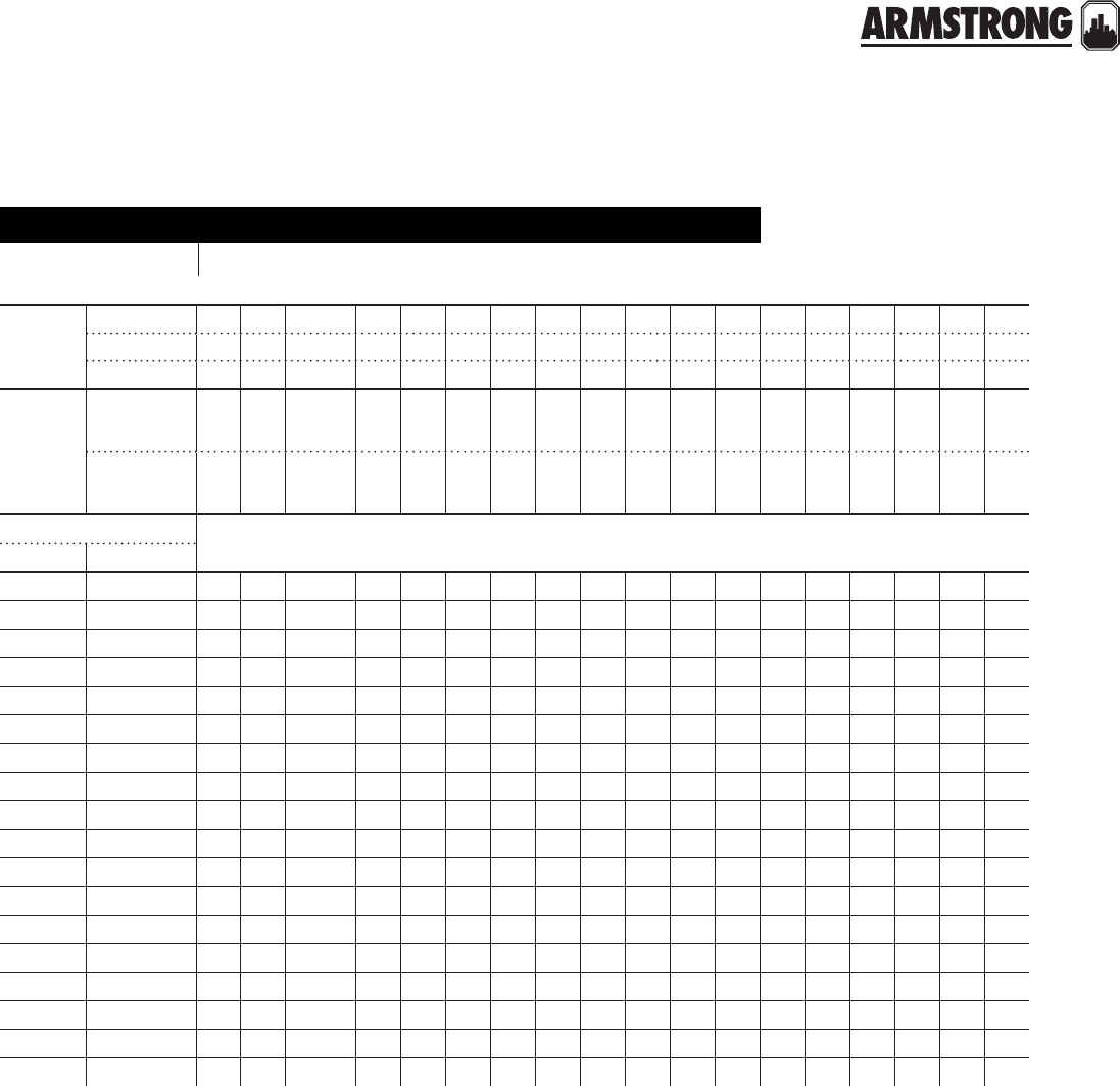
150
|
HYDRONIC SOLUTIONS CATALOG
4030 & 4020 BASE MOUNTED PUMPS
END SUCTION
|
PARTS CROSS REFERENCE
model number
b&g model 1510 armstrong model 4030 bearing frames, all speeds
motor
hp and
speed
1200rpm K O 1 1K 2 3 5 7K 10 - - 15 20 - - 25 30 -
1800rpm O 1 1K & 2 3 5 7K 10 15 20 - - 25 30 - - 40 50 -
3600rpm - - - 5 7K 10 15 20 25 30 40 - - 50 60 - - 75
frame
size
1954 rerate
56
182
184
213
215
254u
256u
284u
286u
324s
326s
324u
326u
364us
365us
364u
365u
404us
1964 rerate
56
143t
145t
182t
184t
213t
215t
254t
256t
284ts
286ts
284t
286t
324ts
326ts
324t
326t
364ts
pump size
b&g armstrong
1¼a 1¼d s s s s s s s - - - - - - - - - - -
1½a 1½d s s s s s s s m m - - - - - - - - -
2a 2d s s s s s s s m m - - - - - - - - -
2½a 2½d s s s s s s s m m m m - - - - - - -
3a 3d - s s s s s s m m m m - - - - - - -
4a 4d - s s s s s s m m m m - - - - - - -
1¼bb 1¼e - s s s s s s m m m m - - - - - - -
1½bb 1½e - s s s s s s m m m m - - - - - - -
2bb 2e - s s s s s s m m m m - - m m - - -
2½b 2½e - - - s s s s - - - - - - - - - - -
3bb 3e - - - s s s s m - - - - - - - - - -
4bb 4e - - - - s s s m m - - - - - - - - -
5bb 5e - - - - - s s m m - - m - - - - - -
6bb 6e - - - - - - - m m - - m - - - - - -
2c 2g - - - - m m m - - - - - - - - - - -
3c 3g - - - - - m m m m - - - - - - - - -
4c 4g - - - - - - m m m - - m m - - - - -
6c 6g - - - - - - - - m - - m m - - m m m
s designation - Y" impeller bore, 1N" mechanical seal
m designation - 1N" impeller bore, 1X" mechanical seal
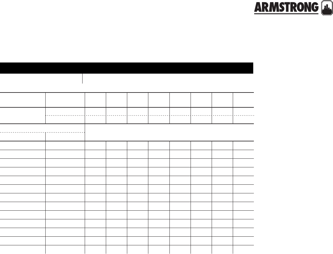
151
|
HYDRONIC SOLUTIONS CATALOG
4030 & 4020 BASE MOUNTED PUMPS
END SUCTION
|
PARTS CROSS REFERENCE
model number
b&g model universal armstrong model 4020 bearing frames, 1750 rpm
motor hp and
speed 1750rpm K & O 1 1K & 2 3 5 7K 10 15
frame size 1954 rerate 56 182 184 213 215 254u 256u 284u
1964 rerate 56 143t 145t 182t 184t 213t 215t 254t
pump size
b&g armstrong
u1¼a 1¼d s s s - - - - -
u1½a 1½d s s s - - - - -
u2a 2d s s s - - - - -
u2½a 2½d s s s s - - - -
u3a 3d - s s s - - - -
u4a 4d - - s s s - - -
u1¼b 1¼e - s s s s - - -
u1½b 1½e - - s s s - - -
u2b 2e - - s s s s - -
u2½b 2½e - - - s s s s -
u3b 3e - - - - s s s -
u4b 4e - - - - s s s s
u5b 5e - - - - - s s s
s designation - Y" impeller bore, 1N" mechanical seal
when replacing the bearing frame assembly on pumps with these motor frame sizes, use the 1510/4030
bearing frame assembly. part no. 819359-002

152
|
HYDRONIC SOLUTIONS CATALOG
4030 & 4020 BASE MOUNTED PUMPS
END SUCTION
|
PARTS CROSS REFERENCE
item 101 volute
pump size material part number
b&g armstrong b&g armstrong
1¼AB & U1¼A1¼DCast iron P41240** 415291-011
Bronze P41260** 415291-041
1½AB & U1½A1½DCast iron P41690 415293-011
Bronze P41710 415293-041
2AB & U2A 2D Cast iron P42070** 425141-011
Bronze P42090** 425141-041
2½A & U2½A2½D Cast iron P42360** 425143-011
3A & U3A*** 3D Cast iron PW-121CI** 425145-011
Bronze PWB-121** 425145-041
4AB & U4A4D Cast iron P43250** 415299-011
Bronze P55280** 415299-041
U1¼B & 1¼BB 1¼ECast iron P41410** 416168-011
Bronze P41430** 416168-041
U1½B & 1½BB 1½E Cast iron P41780 425147-011
U2B & 2BB 2ECast iron P14120** 419153-011
Bronze P42160** 419153-041
U2½B & 2½B2½ECast iron P42480 415297-011
Bronze P55190** 415297-041
U3B & 3BB 3ECast iron P42740 416180-011
Bronze P42770 416180-041
U4B & 4BB 4ECast iron P43310** 415301-011
Bronze P55320** 415301-041
U5B & 5BB 5ECast iron P43620** 415303-011
Bronze P55360** 415303-041
U6B & 6BB 6E Cast iron P43730** 416188-011
2C2GCast iron P42865 419544-011
Bronze — 419544-041
3C3GCast iron P42880 419003-011
Bronze — 419003-041
4C4G Bronze — 419004-041
6C6GCast iron P43810 419542-011
Bronze — 419542-041
notes: ** These volutes are no longer available from B&G. ‘stock at armstrong’
***For pumps built prior to 1964 (serial no. dd) only, use only with impeller part numbers
411868-011 & 411868-041 (Y" bore) and 419234-011 & 419234-041 (1N" bore).
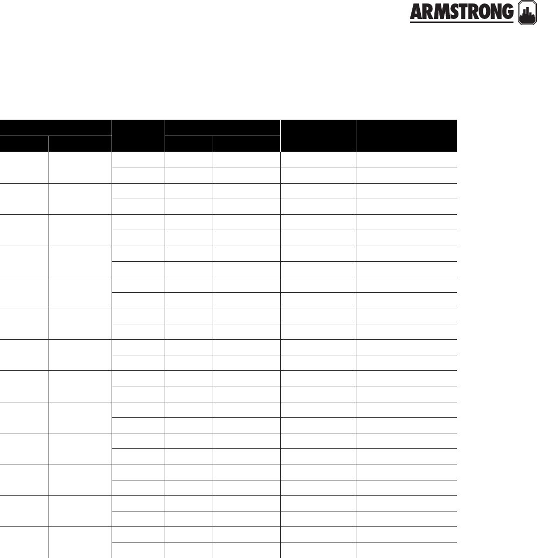
153
|
HYDRONIC SOLUTIONS CATALOG
4030 & 4020 BASE MOUNTED PUMPS
END SUCTION
|
PARTS CROSS REFERENCE
item 102 impeller Y" bore
pump size material part number impeller bore
in inches
maximum
diameter in inches
b&g armstrong b&g armstrong
1¼AB 1¼DBronze P46630 411852-041 Y 7
Cast iron P46510 411852-011 Y 7
1½AB 1½DBronze P47950 411860-041 Y 7
Cast iron P47810 411860-011 Y 7
2AB 2DBronze P47950 411860-041 Y 7
Cast iron P47810 411860-011 Y 7
2½A2½DBronze P48770 406642-041 Y 7
Cast iron P49000 406642-011 Y 7
3A*** 3DBronze P49480 411868-041 Y 7
Cast iron P49500 411868-011 Y 7
4AB 4DBronze P56140 411874-041 Y 7
Cast iron P50270 411874-041 Y 7
1¼BB 1¼EBronze P78523 407922-041 Y9K
Cast iron P78253 407922-011 Y9K
1½BB 1½EBronze P78523 407922-041 Y9K
Cast iron P78253 407922-011 Y9K
2BB 2EBronze P78525 411881-041 Y9K
Cast iron P78486 411881-011 Y9K
2½B2½EBronze P78525 411881-041 Y9K
Cast iron P78486 411881-011 Y9K
3BB 3EBronze P49620 419465-041 Y9K
Cast iron P49600 419465-011 Y9K
4BB 4EBronze P50550 411940-041 Y9K
Cast iron P50390 411940-011 Y9K
5BB 5EBronze P50930 411941-041 Y9K
Cast iron P50910 411941-011 Y9K
notes: *** For pumps built prior to 1964 (serial no. dd) only, use only with casing part numbers: pw-121 for cast iron and pwb-121 for all bronze

154
|
HYDRONIC SOLUTIONS CATALOG
4030 & 4020 BASE MOUNTED PUMPS
END SUCTION
|
PARTS CROSS REFERENCE
item 102 impeller 1N" bore
pump size material part number impeller bore
in inches
maximum
diameter in inches
b&g armstrong b&g armstrong
1½AB 1½DBronze P48070 419229-041 1N 7
Cast iron P48050 419229-011 1N 7
2AB 2DBronze P48070 419229-041 1N 7
Cast iron P48050 419229-011 1N 7
2½A2½DBronze P49040 419232-041 1N 7
Cast iron P48980 419232-011 1N 7
3A*** 3DBronze P49480 419234-041 1N 7
Cast iron P49500 419234-011 1N 7
4AB 4DBronze P50310 419236-041 1N 7
Cast iron P50290 419236-011 1N 7
1¼BB 1¼EBronze P78251 419238-041 1N 9K
Cast iron P78522 419238-011 1N 9K
1½BB 1½EBronze P78251 419238-041 1N 9K
Cast iron P78522 419238-011 1N 9K
2BB 2EBronze P78525 419239-041 1N 9K
Cast iron P78257 419239-011 1N 9K
2½B2½EBronze P78255 419239-041 1N 9K
Cast iron P78257 419239-011 1N 9K
3BB 3EBronze P49640 419241-041 1N 9K
Cast iron P49660 419241-011 1N 9K
4BB 4EBronze P50570 419243-041 1N 9K
Cast iron P50330 419243-011 1N 9K
5BB 5EBronze P50970 419245-041 1N 9K
Cast iron P50950 419245-011 1N 9K
6BB 6EBronze P51290 419247-041 1N 9K
Cast iron P51270 419247-011 1N 9K
2C2GBronze P77497 419543-041 1N 12K
Cast iron P77499 419543-011 1N 12K
3C3GBronze P49700 419008-041 1N 12K
Cast iron P49680 419008-011 1N 12K
4C4GBronze P50450 419009-041 1N 12K
Cast iron P50430 419009-011 1N 12K
6C** 6GBronze P51370 419541-041 1N 12K
Cast iron P51350 419541-011 1N 12K
notes: ** 6 C & 6G Are mechanically interchangeable, providing both the volute and impeller are of the correct size for the capacity conditions at the same time.
6 G 4030 has a possible capacity equivalent of a B&G 8 C, depending on the selection of the proper impeller diameter and motor of adequate capacity.
*** For pumps built prior to 1964 (serial no. dd) only, use only with casing part numbers: pw-121 for cast iron and pwb-121 for all bronze

155
|
HYDRONIC SOLUTIONS CATALOG
4030 & 4020 BASE MOUNTED PUMPS
END SUCTION
|
PARTS CROSS REFERENCE
item 102 impeller Y" bore & 1N" bore (custom size)
pump size material part number impeller bore
in inches
maximum
diameter in inches
b&g armstrong b&g armstrong
U1NA1NDBronze P46630 411852-041 Y 7
Cast iron P46510 411852-011 Y 7
U1KA1KDBronze P47950 411860-041 Y 7
Cast iron P47810 411860-011 Y 7
U2A2DBronze P47950 411860-041 Y 7
Cast iron P47810 411860-011 Y 7
U2KA2KDBronze P48770 406642-041 Y 7
Cast iron P49000 406642-011 Y 7
3A*** 3DBronze P49480 411868-041 Y 7
Cast iron P49500 411868-011 Y 7
U4A4D Cast iron P50270 411874-041 Y 7
U1NB1NEBronze P78523 407922-041 Y9K
Cast iron P78253 407922-011 Y9K
U1KB1KEBronze P78523 407922-041 Y9K
Cast iron P78253 407922-011 Y9K
U2B2EBronze P78525 411881-041 Y9K
Cast iron P78486 411881-011 Y9K
U2KB2KEBronze P78525 411881-041 Y9K
Cast iron P78486 411881-011 Y9K
U3B3EBronze P49620 419465-041 Y9K
Cast iron P49600 419465-011 Y9K
U4B4EBronze P50550 411940-041 Y9K
Cast iron P50390 411940-011 Y9K
U5B5EBronze P50930 411941-041 Y9K
Cast iron P50910 411941-011 Y9K
U6Bn/a Bronze P51290 419247-041 1N 9K
Cast iron P51270 419247-011 1N 9K
notes: *** For pumps built prior to 1964 (serial no. dd) only, use only with casing part numbers: pw-121 for cast iron and pwb-121 for all bronze

156
|
HYDRONIC SOLUTIONS CATALOG
4030 & 4020 BASE MOUNTED PUMPS
END SUCTION
|
PARTS CROSS REFERENCE
item 102 impeller Y" bore & 1N" bore (stock size)
item 117 impeller capscrew
pump size material part number impeller bore
in inches
maximum
diameter in inches
b&g armstrong b&g armstrong
U1T D141 Bronze P48770 406642-041 Y5N
Cast iron P49000 406642-011 Y5N
U2T D142 Bronze P48770 406642-041 Y 6
Cast iron P49000 406642-011 Y 6
U3T D143 Bronze P48770 406642-041 Y6K
Cast iron P49000 406642-011 Y6K
U4T D144 Bronze P48770 406642-041 Y6Y
Cast iron P49000 406642-011 Y6Y
U5T D145 Bronze P78525 411881-041 Y7N
Cast iron P78486 411881-011 Y7N
U6T D146 Bronze P56140 411874-041 Y6K
Cast iron P50270 411874-041 Y6K
U7T D147 Bronze P78525 411881-041 Y 8
Cast iron P78486 411881-011 Y 8
U8T D148 Bronze P50930 411941-041 Y7N
Cast iron P50910 411941-011 Y7N
U9T1NDBronze P78525 411881-041 Y 9
Cast iron P78486 411881-011 Y 9
U10T1KDBronze P50930 411941-041 Y7N
Cast iron P50910 411941-011 Y7N
U11T2DBronze P50550 411940-041 Y8O
Cast iron P50390 411940-011 Y8O
U12T2KDBronze P50930 411941-041 Y9K
Cast iron P50910 411941-011 Y9K
U13 or 14Tn/a Bronze P51290 419247-041 1N 9K
Cast iron P51270 419247-011 1N 9K
pump size impeller bore
in inches construction part number
b&g armstrong
All sizes
Ybf-ab P52320 911900-108
Yab P52350 911900-114
1N bf-ab P13800 911900-113
1N ab P13800 911900-115
notes: *** For pumps built prior to 1964 (serial no. dd) only, use only with casing part numbers: pw-121 for cast iron and pwb-121 for all bronze
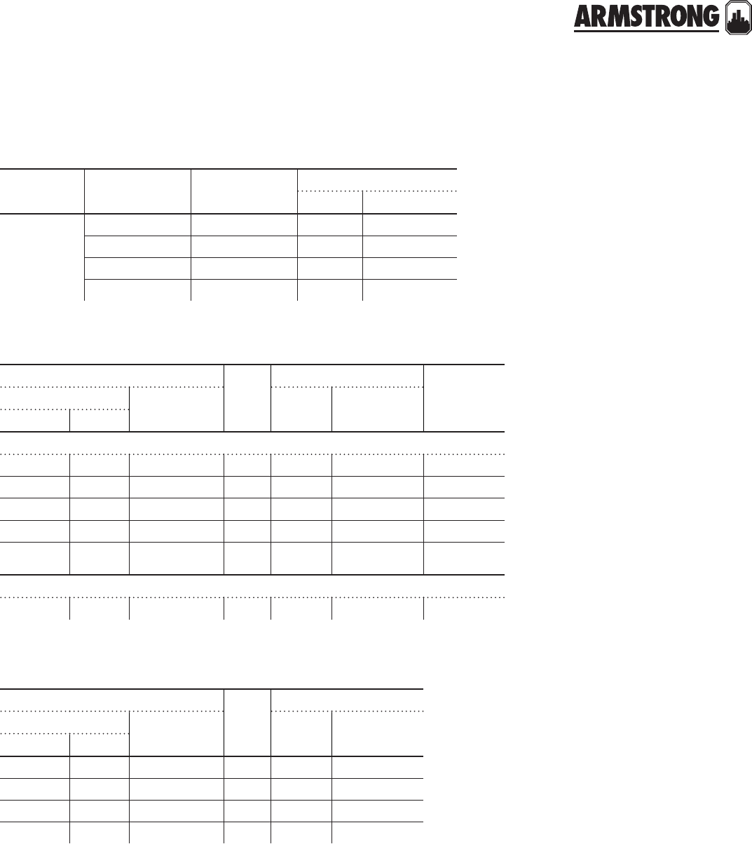
157
|
HYDRONIC SOLUTIONS CATALOG
4030 & 4020 BASE MOUNTED PUMPS
END SUCTION
|
PARTS CROSS REFERENCE
item 118 impeller washer
item 100 bearing frame assembly
item 208 mechanical seal assembly
pump size impeller bore
in inches construction part number
b&g armstrong
All sizes
Ybf-ai P46390 406614-000
Yab P46380 406677-000
1N bf-ai P51250 425742-003
1N ab P51230 425742-003
part number seal
size
construction
style b&g armstrong b&g armstrong
old new
(b&g model 1510b — armstrong model 4030)
P77075 185011 819359-002 1N" bf bf-ai ball brg.
P77222 185012 819359-002 1N" ai bf-ai ball brg.
P77226 185013 819360-002 1N" ab&bfs ab ball brg.
P77074 185014 819310-071 1X" bf bf-ai-ab ball brg.
P77228 185015 819310-071 1X" ai bf-ai-ab ball brg.
(b&g model universal — armstrong model 4020)
P14770 186660 806617-000 1N"bf bf-ai-ab sleeve brg.
part number seal
size
construction
b&g armstrong b&g armstrong
old new
#1 kit 186862 825458-001 1N" bf - ab bf-ab- ai
#4 kit 186860 825458-001 1N" ai bf-ab- ai
#8 kit 186543 811339-000 1X" bf - ab bf - ab
#9 kit 186544 811866-000 1X" ai ai
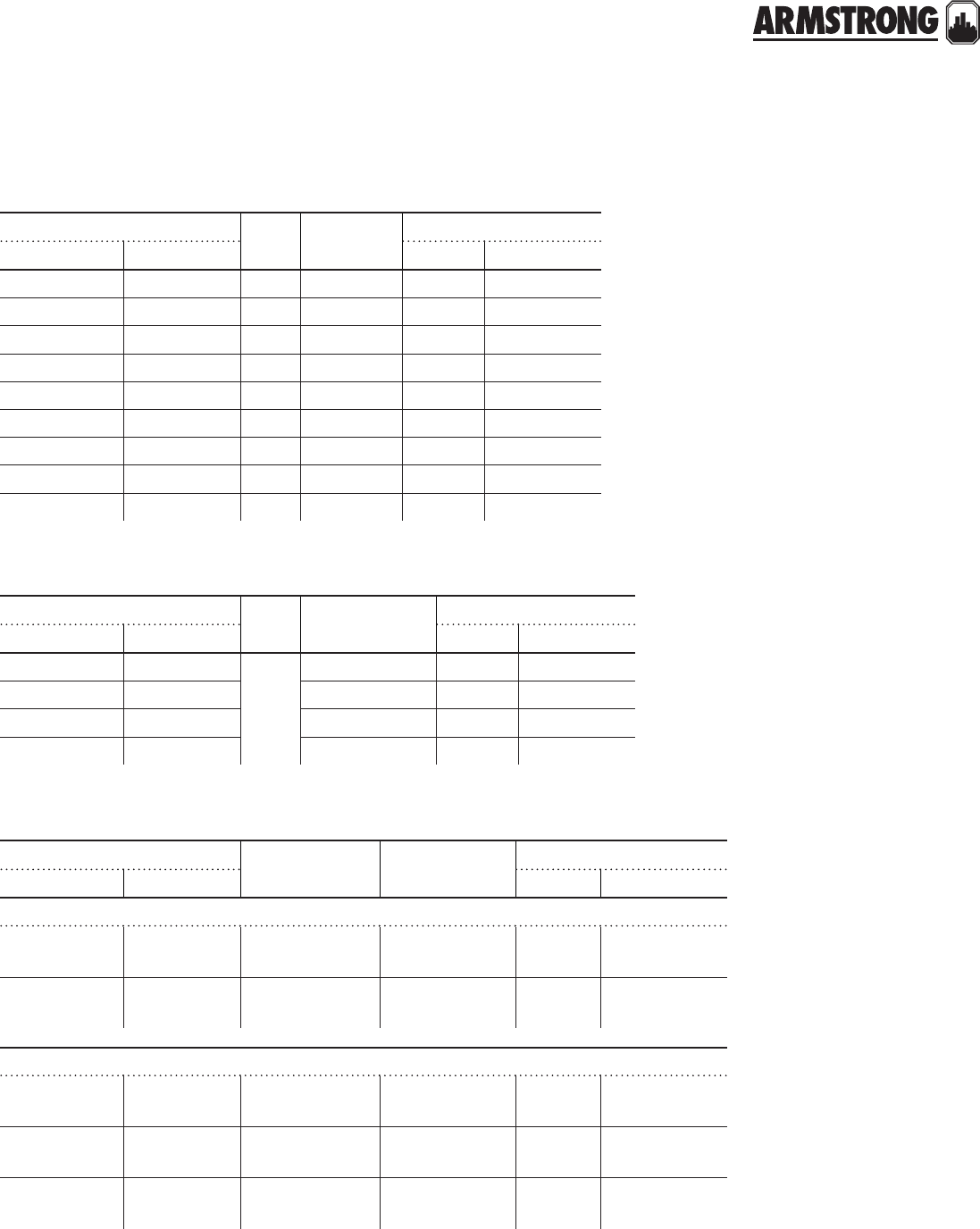
158
|
HYDRONIC SOLUTIONS CATALOG
4030 & 4020 BASE MOUNTED PUMPS
END SUCTION
|
PARTS CROSS REFERENCE
item 201 volute coverplate
item 103 volute gasket
item 104 volute capscrew
pump size seal
size material part number
b&g armstrong b&g armstrong
1NA to 4AB 1ND to 4D1N" Cast iron 186482 409564-011
1NA to 4AB 1ND to 4D1N" Bronze P56779 409564-041
1NBB to 5BB 1NE to 5E1N" Cast iron 186495 409563-011
1NBB to 5BB 1NE to 5E1N" Bronze P56799 409563-041
3A to 4AB 2D to 4D1X" Cast iron P49940 414498-011
3A to 4AB 2D to 4D1X" Bronze P49960 414498-041
1NBB to 6BB 1NE to 6E1X" Cast iron P51540 411896-011
1NBB to 6BB 1NE to 6E1X" Bronze P51560 411896-041
2C to 8C2G to 8G1X" Cast iron P50670 419467-011
pump size seal
size construction part number
b&g armstrong b&g armstrong
1NA to 4AB 1ND to 4D
1N"
and
1X"
bf,ai,ab P57700 106592-000
1NBB to 5BB 1NE to 5Ebf,ai,ab P48690 406604-000
1NBB to 6BB 1NE to 6Ebf,ai,ab P48690 406604-000
2C to 8C2G to 8Gbf,ai,ab P57770 419016-000
pump size construction no. required
size
part number
b&g armstrong b&g armstrong
‘s’ size Y" impeller bore - 1" shaft diameter at coupler
1NAB to 4AB 1ND to 4DAll 8 required
W-16NCx1" P40020 911121-108
1NBB to 5BB 1NE to 5EAll 12 required
G⁄af-14NCx1" S03980 911123-108
‘m’ size 1N" impeller bore - 1N" shaft diameter at coupler
1NAB to 4AB 1ND to 4DAll 8 required
W-16x2X" P44250 911121-120
1NBB to 5BB 1NE to 5EAll 12 required
G⁄af-14NCx1N" P03470 911123-110
2C to 8C2G to 8GAll 12 required
K-13NCx1K" P13780 911125-116
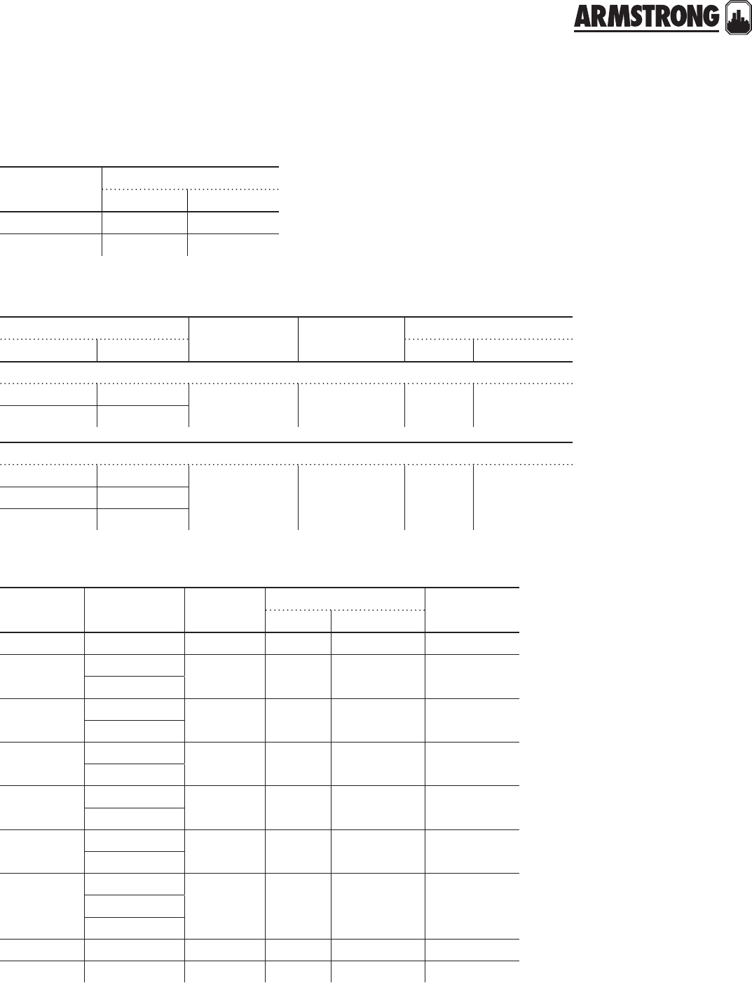
159
|
HYDRONIC SOLUTIONS CATALOG
4030 & 4020 BASE MOUNTED PUMPS
END SUCTION
|
PARTS CROSS REFERENCE
item 342 water slinger
item 202 coverplate capscrew
item 401 coupler selection table ( woods type )
pump shaft
diameter
part number
b&g armstrong
1N" PW - 6286 406622-000
1X" PW - 8286 419315-000
pump size construction no. required
size
part number
b&g armstrong b&g armstrong
‘s’ size Y" impeller bore - 1" shaft diameter at coupler
1NAB to 4AB 1ND to 4DAll 4 required
W-16NCx1" P40020 911121-108
1NBB to 5BB 1NE to 5E
‘m’ size 1N" impeller bore - 1N" shaft diameter at coupler
1NAB to 4AB 1ND to 4D
All 4 required
W-16x1N"
P55420 911121-1101NBB to 5BB 1NE to 5E
2C to 8C2G to 8G
pump
shaft size
motor
frame size
motor
shaft size
coupler part number woods size
b&g armstrong
1" 56 X" 186868 819340-002 4J
1" 143T - 145TY" 186869 819341-002 4J
182 - 184
1" 182T - 184T1V"
186870 819342-002 5J
213 - 215
1" 213T - 215T1W" 186871 819344-002 6J
254U - 256U
1" 254T - 256T 1X" 186873 819347-002 7J
284U
1N" 254U -256U1W" 186872 819344-012 6J
213T - 215T
1N"
254T - 256T
1X" P63239 819348-002 7J 284U
284T - 286T
1N" 324U1Y" P63242 819349-002 8J
1N" 324T - 326T2V" P63245 819350-002 9E

160
|
HYDRONIC SOLUTIONS CATALOG
4030 & 4020 BASE MOUNTED PUMPS
END SUCTION
|
PARTS CROSS REFERENCE
item 407 coupler insert selection table ( woods type )
insert size
‘woods’
part number
b&g armstrong
4J P78804 875000-801
5J P78729 875000-802
6J P78791 875000-803
7J P78792 875000-804
9JPP78796 875000-807
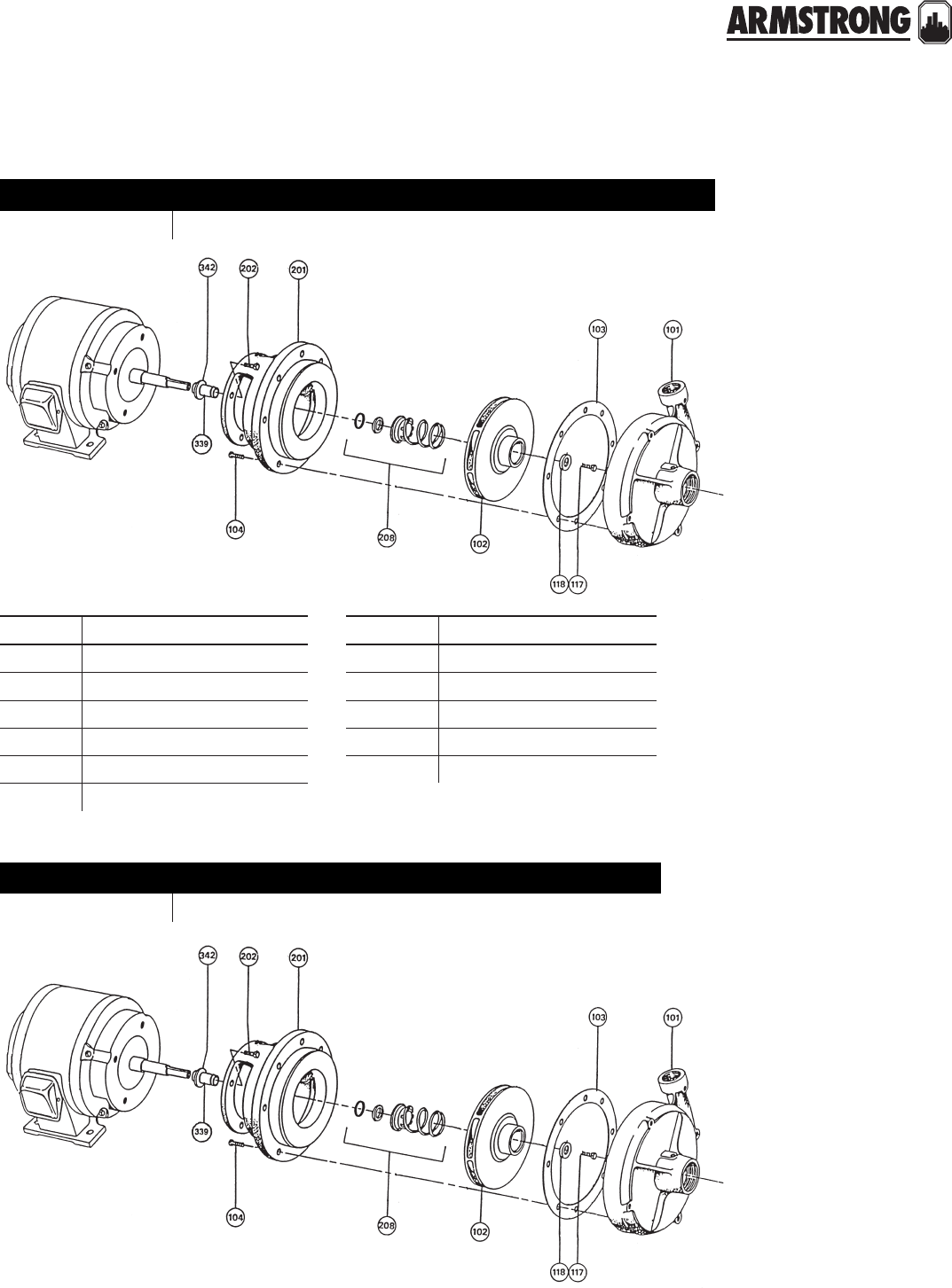
161
|
HYDRONIC SOLUTIONS CATALOG
4280 MOTOR MOUNTED PUMPS
CLOSE COUPLED
|
PARTS CROSS REFERENCE
item description item description
101 Volute 201 Volute cover plate
102 Impeller 202 m/p bracket capscrew
103 Volute gasket 208 Mechanical seal assembly
104 Volute capscrew 339 Shaft sleeve kit
117 Impeller capscrew 342 Water slinger
118 Impeller washer
model number
b&g model 1531b armstrong model, 4280 power frames, all speeds
model number
b&g model 1531 armstrong 4280 old style, tangential, motor mounted pumps
back to
contents
<
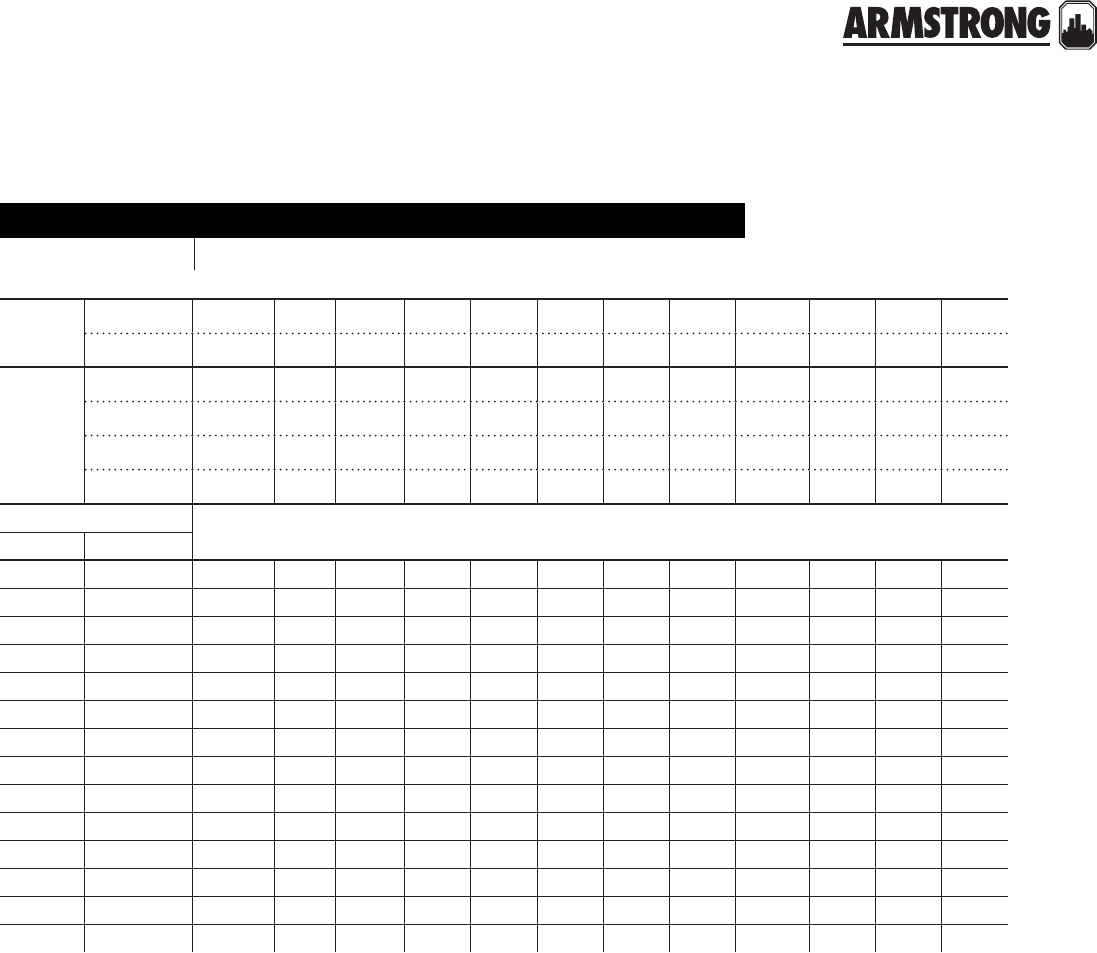
162
|
HYDRONIC SOLUTIONS CATALOG
4280 MOTOR MOUNTED PUMPS
CLOSE COUPLED
|
PARTS CROSS REFERENCE
model number
b&g model 1531b armstrong model, 4280 power frames, all speeds
motor
hp and
speed
1800rpm ½ ,¾ &1 1½&2 3 5 7½ 10 15 20 25 30 40 50
3600rpm 1½ 2&3 5 7½ 10 15 20 25 30 40 50 60
frame
size
1954 rerate 182c 184c 213c 215c 254uc 256uc 284uc 286uc 324uc 326sc
1964 rerate 143jm 145jm 182jm 184jm 213jm 215jm 254jm 256jm 284jm 286jm
west coast 254tcz 256tcz 284tcz 286tcz 324tcz 326tcz
1972 rerate 254jp 256jp 284jp 286jp 324jp 326jp
pump size
b&g armstrong
1¼ab 1¼d s s s s s - - - - - - -
1½ab 1½d s s s s s s - - - - - -
2ab 2d s s s s s s - - - - - -
2½a 2½d s s s s s s m - - - - -
3a 3d s s s - s s m m - - - -
4ab 4d - s s s - s m m m m - -
1¼bb 1¼e - s s s - s m m m - - -
1½bb 1½e - s s s - s m m m m - -
2bb 2e - s s s s - m m m m m -
2½bb 2½e - - s s s - - - - - - -
3bb 3e - - - s s - - - - - - -
4bb 4e - - - s s s m - - - - -
5bb 5e - - - - s s m m - - - -
6bb 6e - - - - - - m m m - - -
s designation - Y" impeller bore, 1N" mechanical seal
m designation - 1N" impeller bore, 1X" mechanical seal

163
|
HYDRONIC SOLUTIONS CATALOG
4280 MOTOR MOUNTED PUMPS
CLOSE COUPLED
|
PARTS CROSS REFERENCE
item 101 volute
pump size material part number
b&g armstrong b&g armstrong
1¼AB 1¼DCast iron P41200** 415290-011
Bronze P41220** 415290-041
1½AB 1½DCast iron P41690 415293-011
Bronze P41710 415293-041
2AB 2D Cast iron P42070** 425141-011
Bronze P42090** 425141-041
2½A 2½DCast iron P42360** 425143-011
Bronze P42360** 425143-011
3A*** 3D Cast iron PW-121CI** 425145-011
Bronze PWB-121** 425145-041
4AB 4D Cast iron P43250** 415299-011
Bronze P55280** 415299-041
1¼BB 1¼ECast iron P41410** 416168-011
Bronze P41430** 416168-041
1½BB 1½E Cast iron P41780 425147-011
2BB 2ECast iron P14120** 419153-011
Bronze P42160** 419153-041
2½B2½ECast iron P42480 415297-011
Bronze P55190** 415297-041
3BB 3ECast iron P42740 416180-011
Bronze P42770 416180-041
4BB 4ECast iron P43310** 415301-011
Bronze P55320** 415301-041
5BB 5ECast iron P43620** 415303-011
Bronze P55360** 415303-041
6BB 6E Cast iron P43730** 416188-011
2C2GCast iron P42865 419544-011
Bronze — 419544-041
3C3GCast iron P42880 419003-011
Bronze — 419003-041
4C4G Bronze — 419004-041
6C6GCast iron P43810 419542-011
Bronze — 419542-041
notes: ** These volutes are no longer available from B&G. ‘stock at armstrong’
***For pumps built prior to 1964 (serial no. dd) only, use only with impeller part numbers
411868-011 & 411868-041 (Y" bore) and 419234-011 & 419234-041 (1N" bore).

164
|
HYDRONIC SOLUTIONS CATALOG
4280 MOTOR MOUNTED PUMPS
CLOSE COUPLED
|
PARTS CROSS REFERENCE
item 102 impeller Y" bore
pump size material part number impeller bore
in inches
maximum
diameter in inches
b&g armstrong b&g armstrong
1¼AB 1¼DBronze P46630 411852-041 Y 7
Cast iron P46510 411852-011 Y 7
1½AB 1½DBronze P47950 411860-041 Y 7
Cast iron P47810 411860-011 Y 7
2AB 2DBronze P47950 411860-041 Y 7
Cast iron P47810 411860-011 Y 7
2½A2½DBronze P49000 406642-041 Y 7
Cast iron P48770 406642-011 Y 7
3A*** 3DBronze P49480 411868-041 Y 7
Cast iron P49500 411868-011 Y 7
4AB 4DBronze P56140 411874-041 Y 7
Cast iron P50270 411874-041 Y 7
1¼BB 1¼EBronze P78523 407922-041 Y9K
Cast iron P78253 407922-011 Y9K
1½BB 1½EBronze P78523 407922-041 Y9K
Cast iron P78253 407922-011 Y9K
2BB 2EBronze P78525 411881-041 Y9K
Cast iron P78486 411881-011 Y9K
2½B2½EBronze P78525 411881-041 Y9K
Cast iron P78486 411881-011 Y9K
3BB 3EBronze P49620 419465-041 Y9K
Cast iron P49600 419465-011 Y9K
4BB 4EBronze P50550 411940-041 Y9K
Cast iron P50390 411940-011 Y9K
5BB 5EBronze P50930 411941-041 Y9K
Cast iron P50910 411941-011 Y9K
notes: *** For pumps built prior to 1964 (serial no. dd) only, use only with casing part numbers: pw1-121ci for cast iron and pw1-121cb for all bronze
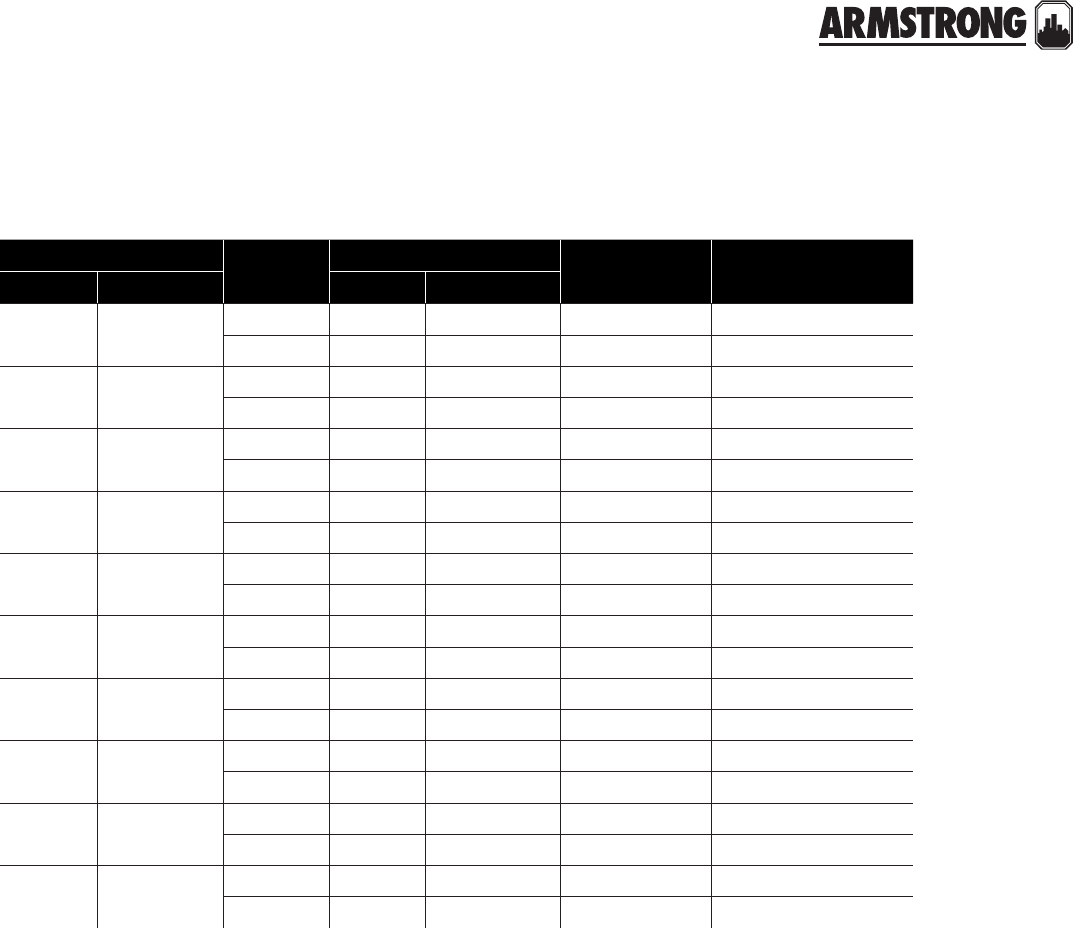
165
|
HYDRONIC SOLUTIONS CATALOG
4280 MOTOR MOUNTED PUMPS
CLOSE COUPLED
|
PARTS CROSS REFERENCE
notes: *** For pumps built prior to 1964 (serial no. dd) only, use only with casing part numbers: pw1-121ci for cast iron and pw1-121cb for all bronze
item 102 impeller 1N" bore
pump size material part number impeller bore
in inches
maximum
diameter in inches
b&g armstrong b&g armstrong
2½A2½DBronze P49040 419232-041 1N 7
Cast iron P48980 419232-011 1N 7
3A*** 3DBronze P49480 419234-041 1N 7
Cast iron P49500 419234-011 1N 7
4AB 4DBronze P50310 419236-041 1N 7
Cast iron P50290 419236-011 1N 7
1¼BB 1¼EBronze P78251 419238-041 1N 9K
Cast iron P78522 419238-011 1N 9K
1½BB 1½EBronze P78251 419238-041 1N 9K
Cast iron P78522 419238-011 1N 9K
2BB 2EBronze P78255 419239-041 1N 9K
Cast iron P78257 419239-011 1N 9K
3BB 3EBronze P49640 419241-041 1N 9K
Cast iron P49660 419241-011 1N 9K
4BB 4EBronze P50570 411940-041 1N 9K
Cast iron P50330 411940-011 1N 9K
5BB 5EBronze P50970 419245-041 1N 9K
Cast iron P50950 419245-011 1N 9K
6BB 6EBronze P51290 419247-041 1N 9K
Cast iron P51270 419247-011 1N 9K

166
|
HYDRONIC SOLUTIONS CATALOG
4280 MOTOR MOUNTED PUMPS
CLOSE COUPLED
|
PARTS CROSS REFERENCE
item 201 motor/pump brackets
pump size motor frame
size
seal
size construction part number
b&g armstrong b&g armstrong
1NAB to 4AB 1ND to 4D
143t-145t
143jm-145jm
182-184
182jm-184jm
1N" bf-ai 186526 409026-012
1NAB to 4AB 1ND to 4D
143t-145t
143jm-145jm
182-184
182jm-184jm
1N" ab P56929 409026-042
1NAB to 4AB 1ND to 4D
213-215
182t-184t
254u-256u
213t-215t
213jm-215jm
1N" bf-ai 186528 406931-012
1NAB to 4AB 1ND to 4D
213-215
182t-184t
254u-256u
213t-215t
213jm-215jm
1N" ab P56939 406931-042
1NBB to 5BB 1NE to 5E
143t-145t
143jm-145jm
182-184
182jm-184jm
1N" bf-ai 186533 409023-012
1NBB to 5BB 1NE to 5E
143jm-145jm
182-184
182jm-184jm
1N" ab P56969 409023-042
1NBB to 5BB 1NE to 5E
213-215
182t-184t
254u-256u
213t-215t
213jm-215jm
1N" bf-ai 186530 406948-012
1NBB to 5BB 1NE to 5E
213-215
182t-184t
254u-256u
213t-215t
213jm-215jm
1N" ab P56949 406953-042
1NAB to 4AB 1ND to 4D254t-256t
254jp-256jp 1X" bf-ai P77076 425392-012
1NAB to 4AB 1ND to 4D254t-256t
254jp-256jp 1X" ab P77073 425392-042

167
|
HYDRONIC SOLUTIONS CATALOG
4280 MOTOR MOUNTED PUMPS
CLOSE COUPLED
|
PARTS CROSS REFERENCE
item 201 motor/pump brackets
pump size motor frame
size
seal
size construction part number
b&g armstrong b&g armstrong
1NAB to 4AB 1ND to 4D284u-286u
284t-286t 1X" bf-ai P53690 419164-012
1NAB to 4AB 1ND to 4D284u-286u
284t-286t 1X" ab P53710 419168-042
1NAB to 4AB 1ND to 4D
284jp-286jp
324u-326u
324t-326t
324jp-326jp
364t-365t
364jp-365jp
404-405
1X" bf-ai P53880 419165-012
1NAB to 4AB 1ND to 4D
284jp-286jp
324u-326u
324t-326t
324jp-326jp
364t-365t
364jp-365jp
404-405
1X" ab P53900 419165-042
1NBB to 6BB 1NE to 6E254t-256t
254jp-256jp 1X" bf-ai P77166 425393-012
1NBB to 6BB 1NE to 6E254t-256t
254jp-256jp 1X" ab P77169 425393-042
1NBB to 6BB 1NE to 6E284u-286u
284t-286t 1X" bf-ai P53020 419166-012
1NBB to 6BB 1NE to 6E284u-286u
284t-286t 1X" ab P53040 419170-042
1NBB to 6BB 1NE to 6E
284jp-286jp
324u-326u
324t-326t
324jp-326jp
364t-365t
364jp-365jp
404-405
1X" bf-ai P53500 411883-012
1NBB to 6BB 1NE to 6E
284jp-286jp
324u-326u
324t-326t
324jp-326jp
364t-365t
364jp-365jp
404-405
1X" bf-ai P53540 419171-042
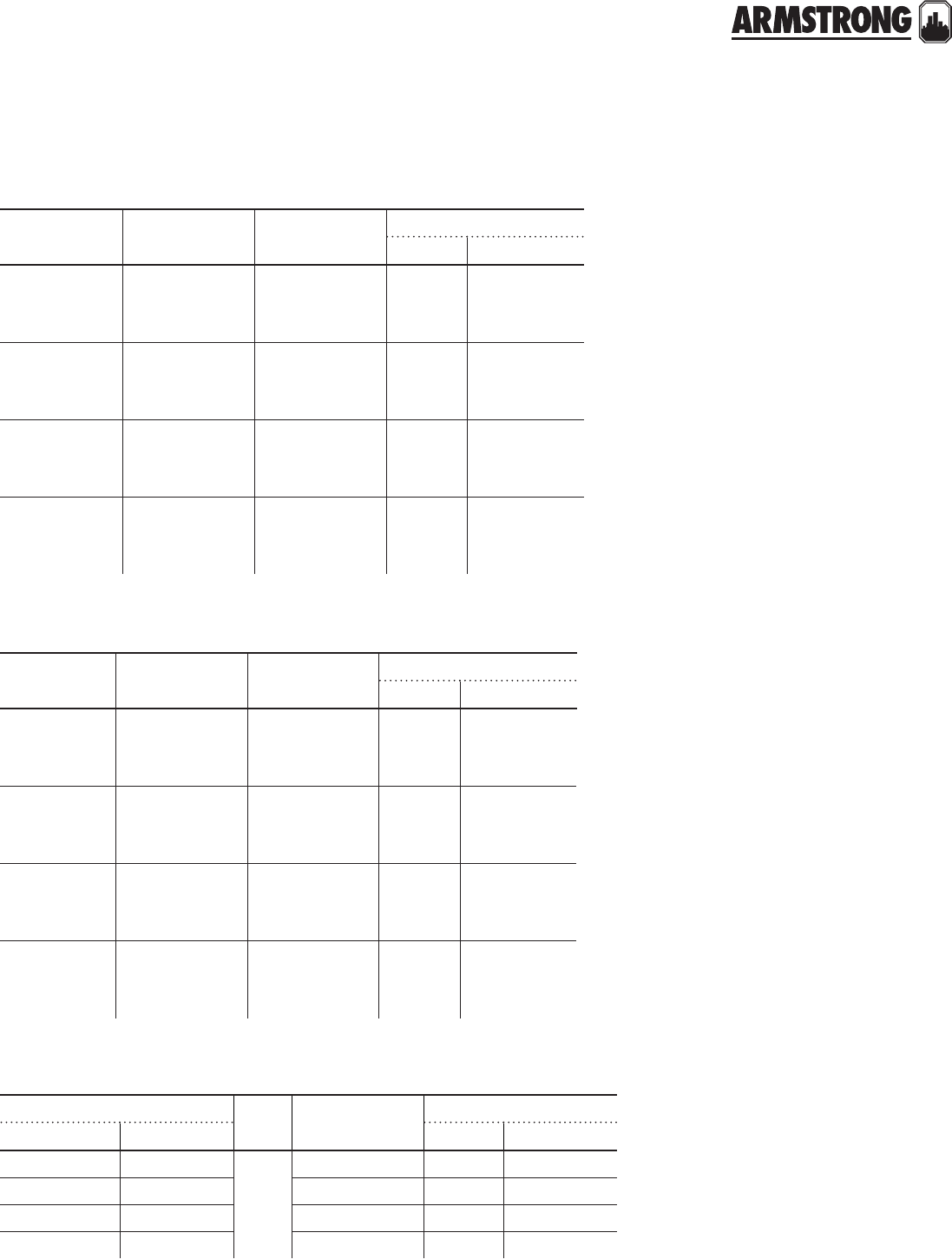
168
|
HYDRONIC SOLUTIONS CATALOG
4280 MOTOR MOUNTED PUMPS
CLOSE COUPLED
|
PARTS CROSS REFERENCE
item 117 impeller capscrew
motor
frame size
impeller bore
in inches construction part number
b&g armstrong
143t to 215t
143jm to 215jm
254u to 256u
Ybf-ab P52320 911900-108
143t to 215t
143jm to 215jm
254u to 256u
Yai P52350 911900-114
254t to 365t
254jp to 365jp
284u to 326u
1N bf-ab P13800 911900-113
254t to 365t
254jp to 365jp
284u to 326u
1N ai P13800 911900-115
item 118 impeller washer
motor
frame size
impeller bore
in inches construction part number
b&g armstrong
143t to 215t
143jm to 215jm
254u to 256u
Ybf-ai P46930 406614-000
143t to 215t
143jm to 215jm
254u to 256u
Yab P46380 406677-000
254t to 365t
254jp to 365jp
284u to 326u
1N bf-ai P51250 425742-003
254t to 365t
254jp to 365jp
284u to 326u
1N ab P51230 425742-003
item 103 volute gasket
pump size seal
size construction part number
b&g armstrong b&g armstrong
1NA to 4AB 1ND to 4D
1N"
and
1X"
bf,ai,ab P57700 106592-000
1NBB to 5BB 1NE to 5Ebf,ai,ab P48690 406604-000
3A to 4AB 2D to 4Dbf,ai,ab P57700 106592-000
1NBB to 6BB 1NE to 6Ebf,ai,ab P48690 406604-000
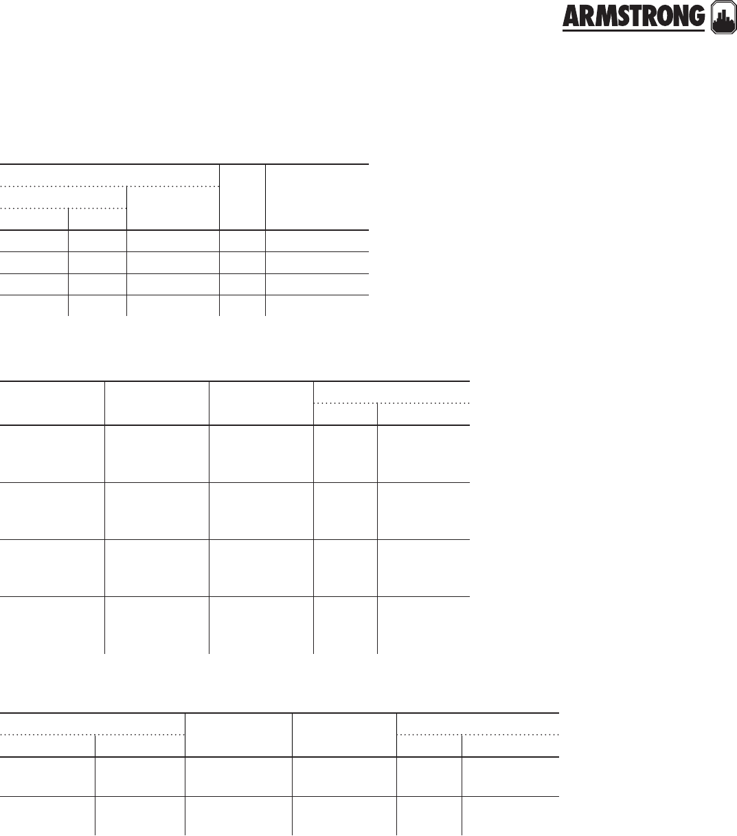
169
|
HYDRONIC SOLUTIONS CATALOG
4280 MOTOR MOUNTED PUMPS
CLOSE COUPLED
|
PARTS CROSS REFERENCE
item 339 shaft sleeve & spacer kit
item 208 mechanical seal assembly
motor frame
size
impeller bore
in inches construction part number
b&g kit armstrong
143t to 215t
143jm to 215jm
254u to 256u
1N bf-ab 185024 835085-001
143t to 215t
143jm to 215jm
254u to 256u
1N ai 185025 835085-002
254t to 365t
254jp to 365jp
284u to 326u
1X bf-ab 185021 810150-152
254t to 365t
254jp to 365jp
284u to 326u
1X ai 185022 810150-153
part number seal
size constructionb&g armstrong
old new
#1 kit 186862 825458-001 1N" bf - ab
#4 kit 186860 825458-001 1N" ai
#8 kit 186543 811339-000 1X" bf - ab
#9 kit 186544 811866-000 1X" ai
item 104 volute capscrew
pump size construction no. required
size
part number
b&g armstrong b&g armstrong
1NAB to 4AB 1ND to 4DAll 8 required
W-16NCx1" P40020 911121-108
1NBB to 6BB 1NE to 6EAll 12 required
G⁄af-14NCx1" P03470 911123-108
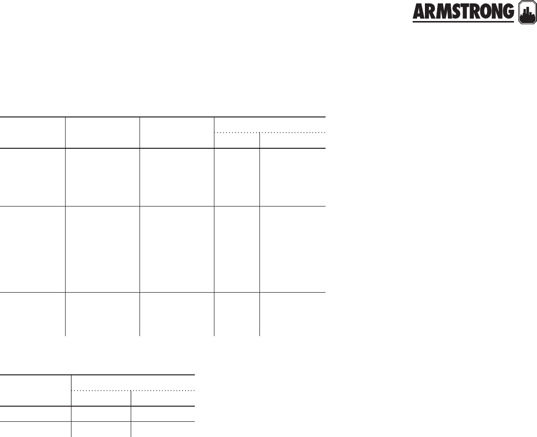
170
|
HYDRONIC SOLUTIONS CATALOG
4280 MOTOR MOUNTED PUMPS
CLOSE COUPLED
|
PARTS CROSS REFERENCE
item 342 water slinger
item 202 motor capscrew
pump shaft
diameter
part number
b&g armstrong
1N" PW - 6286 406622-000
1X" PW - 8286 419315-000
motor
frame size construction number
required size
part number
b&g armstrong
143t-145t
143jm-145jm
182-184
182jm-184jm
All 4 required
W-16NCx1N" P46930 406614-000
213c-256uc
213t-256t
213jm-215jm
254u-256u
284u-286u
284jp-286jp
All 4 required
K-13NCx1N" P46380 406677-000
324uc-405uc
324jp-326jp
404-405
All 4 required
X-11NCx1N" P51250 425742-003
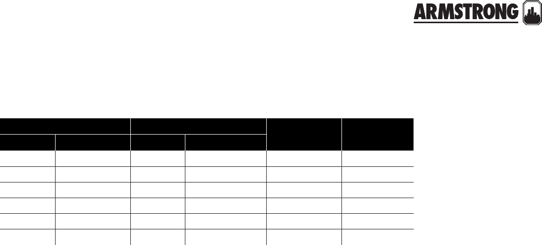
171
|
HYDRONIC SOLUTIONS CATALOG
SHELL & TUBE HEAT EXCHANGERS
PARTS CROSS REFERENCE
heat exchanger tube bundle shell gasket head gasket
grainger armstrong grainger armstrong
2p861 ws-0403-2-1 2p862 rtb ws-0403-2-1 691300-001 691301-001
2p863 ws-0404-2-1 2p864 rtb ws-0404-2-1 691300-001 691301-001
2p865 ws-0603-2-1 2p866 rtb ws-0603-2-1 691300-002 691301-002
2p867 ws-0604-2-1 2p868 rtb ws-0604-2-1 691300-002 691301-002
2p869 ws-0605-2-1 2p870 rtb ws-0605-2-1 691300-002 691301-002
2p871 ws-0804-2-1 2p872 rtb ws-0804-2-1 691300-003 691301-003
part numbers
back to
contents
<
172
|
HYDRONIC SOLUTIONS CATALOG
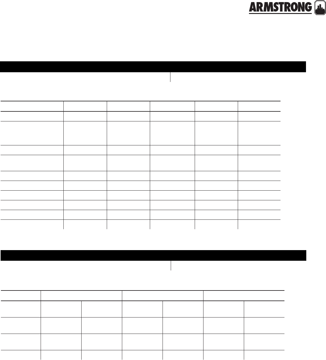
173
|
HYDRONIC SOLUTIONS CATALOG
4380 & 4360 VIL PUMPS
CENTRIFUGAL CLOSE-COUPLED
|
PARTS CROSS REFERENCE
model number
teel / grainger 4p934, 4p935, 4p936, 4p937, 4p938 armstrong model 4380 bf
description 2×2×8 3×3×8 4×4×8 4×4×10 6×6×8
Casing 427027-011 427151-011 427053-011 427063-011 427055-011
Motor
3hp/1750/60/3/
208/230/460-
182jm frame
5hp/1750/60/3/
208/230/460-
184jm frame
7.5hp/1750/60/3/
208/230/460-
213jp frame
10hp/1750/60/3/
208/230/460-
215jp frame
15hp/1750/60/3/
208/230/460-
254jm frame
Motor bracket/adapter 426749-011 426749-011 426750-011 426754-015 426751-015
Impeller 427121-041
8"Max. od.
427129-041
8"Max. od.
427138-041
8"Max. od.
427150-041
10"Max. od.
427140-041
8"Max. od.
Seal kit 975000-991 975000-991 975000-993 975000-993 975000-993
Sleeve and spacer 810150-150 810150-150 810150-152 810150-152 810150-154
Casing gasket 426401-003 426401-003 426401-003 426401-004 426401-004
Water slinger 406622-000 406622-000 406622-000 406622-000 406622-000
Impeller washer 425742-001 425742-001 425742-003 425742-003 425742-003
Impeller capscrew 911900-114 911900-114 911900-119 911900-119 911900-119
part numbers
model number
teel / grainger 4p930, 4p931, 4p932, 4p933 armstrong ‘d’ series 4360 bf
description 1K D2 D3 D
Casing 116397-011
c.i.
116397-041
Bronze
116174-011
c.i.
116174-041
Bronze
116646-011
c.i.
116646-041
Bronze
Impeller Y"
bore
426993-011
Steel
426993-041
Bronze
411860-011
Steel
411860-041
Bronze
426994-041
Bronze
Flanges 104301-011
c.i.
104301-041
Bronze
106074-011
c.i.
106074-041
Bronze
133615-011
c.i.
133615-041
Bronze
Flange gasket 104034-000 116117-000 125606-106
part numbers
back to
contents
<
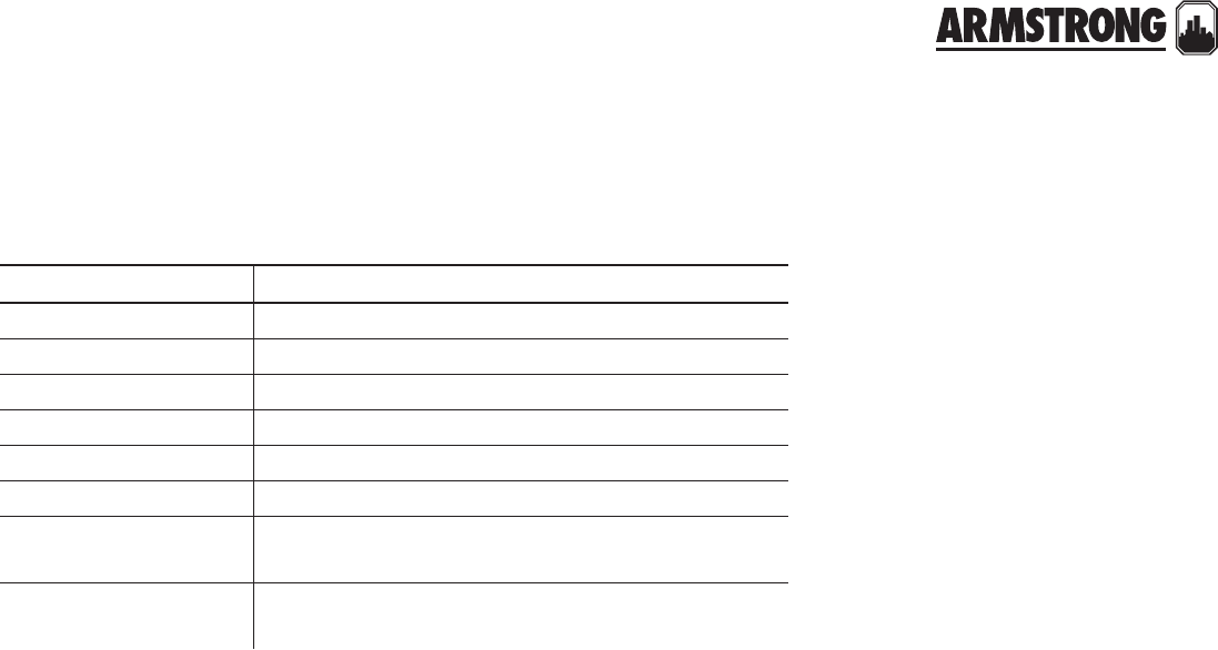
174
|
HYDRONIC SOLUTIONS CATALOG
4380 & 4360 VIL PUMPS
CENTRIFUGAL CLOSE-COUPLED
|
PARTS CROSS REFERENCE
description part number
Casing gasket 106592-000
Seal kit 825458-001
Sleeve and spacer 835085-001
Water slinger 406622-000
Impeller washer 425742-001
Impeller capscrew 911900-114
Adapter/Motor bracket 426991-011 (pumps built prior to serial no. 99808)
426989-011 (pumps built after serial no. 99807)
Flush line 1 ea. 997531-004 W"µ 12" µ .032 wall copper tube
2 ea. 939001-114 W"µ N" npt elbow
common parts
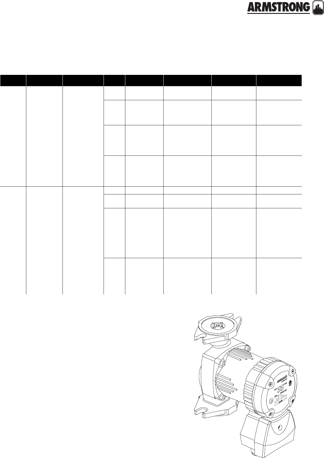
175
|
HYDRONIC SOLUTIONS CATALOG
DESIGN ENVELOPE COMPASS CIRCULATORS
CROSS REFERENCE
models armstrong part number speed b & g grundfos wilo taco
Cast iron compa ss
20-20 ci 180203-606
vs3Ecocirc Auto /
Vario
alpha 15-55f/f-lc,
alpha 15-55fr/fr-lc2
Stratos eco 16f/rfc,
16fx2Bumble bee (hec-2)
1—
ups 15-42f s1,
ups 15-58fc s1,
up 15-10f,
ups 26-99fc s1
star s 16f s1 —
2nrf-25 s11,
nrf-9f/lw2
ups 15-42f s2,
ups 15-58fc s2
star s 16f s2,
star s 21f s1
005-f2-3-ifc2,
006-f4/-f7-ifc,
007-f5-5/-8-ifc2,
00r/0015-f6i ifc/-
msf2-1 ifc s1
3nrf-222,
nrf-25 s21
up 15-42f,
ups 15-42f s3,
ups 15-58fc s3,
ups 26-99fc s1,
ups 43-44fc s1
star s 16f s3,
star 16f,
star s 21f s2 & s3
008-f6-i-ifc,
00r-f6-i-ifc ,
00r/0015-msf2-1 ifc
s2 & s3
Stainless
steel
compass
20-20 ss 180203-607
vs3— alpha 15-55sf/sf-lc Stratos eco 16bfx2—
1— — star 5 bu1, star s
16bf s1 003–sc4–1/fc
2
nbf/ssf-9u/lw1,
nbf/ssf-12u/lw1,
nbf/ssf-12f/lw2,
nbf-25 s1
up 15-18buc 5/71 ,
up 15-29su1,
up 15-35suc,
ups 15-35suc s2 1,
ups 15-35sfc s1 & s2,
up 15-18sf,
ups 15-55sfc s12
star 81,
star s 16bf s2,
star s 21bfx s1
005-bf2/-i-ifc2,
005-sf2/-ifc2,
006-bc4-i,
006-b7-ifc,
006–sc4-1,
006–sc7–1fc ,
007-bf5/-i-ifc2,
007-sf5/-ifc2
3nbf/ssf-222,
nbf-25 s21
ups 15-35sfcs3,
ups 15-55sfc s2 & s32 ,
up 15-42sf,
up 25-64sf ,
ups 26-99bfc s1,
ups 43-44bfc s1
star 11 bu1, star s
16bf s3,
star 16bf,
star s 21bfx s2 & s3
008-bc6,
008-bc6-ifc,
008-sf6/-ifc2,
00r/0015–sf6–ifc,
00r/0015–sf6–1–ifc2
notes:
1 Dimension and connection may vary.
2 Flange orientation may vary.
3 Variable speed operation mode.
Compass can functionally replace fixed speed as well as variable speed products.
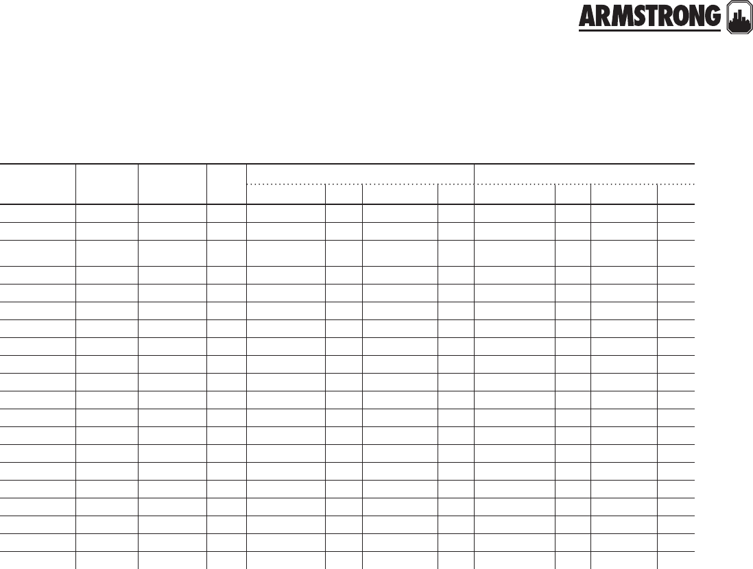
176
|
HYDRONIC SOLUTIONS CATALOG
S&H CIRCULATORS
|
CROSS REFERENCE
armstrong b& g grundfos taco port to port length (inches) motor size (nominal hp)
armstrong b&g grundfos taco armstrong b&g grundfos taco
S-25 Series 100 up 26-64f #110 6½ 6W 6½ 6E/af A/ab A/ab A/ab A/ab
S-35 2" up 50-44f #120 8½ 8½ 8½ 11 T T T T
S-45 2½", ld3 —#121,
#122 10 10 —11V ¼ ¼ —¼
S-46 hd3 —#131 10 10 —13X L L —L
S-55 pd-35 —#132 12 12 —13X ½ ½ —½
S-57 pd-37 —#133 12 12 —13X ¾ ¾ —¾
S-69 pd-38, 40 —#138 14¼ 14½ —13X 1 1 , 1½ —1
H-32 hv up 43-44 #111 8½ 8½ 8½ 8¾ T T T T
H-41 1"pr up 26-64F #113 8½ 8½ 6½ 8½ T T A/ab V
H-52 60-11 ups 32-80 #1600 11½ 11 11 10¼ ¼ ¼ ½ ¼
S-35 —ups 40-40 #1610 11½ —13½ 10¼ L - L L
H-53 60-13 ups 40-160 #1612 11½ 11½ 13½ 13½ ½ ½ ¾ ½
H-54 60-14 ups 50-80/2 #1632 11½ 11½ 11½ 13½ ¾ ¾ ¾ ¾
H-63 60-15 ups 32-160 #1612 13½ 13½ 13½ 13½ ½ ½ ¾ ½
H-64 60-16 ups 32-160 #1614 13½ 13½ 13½ 13½ ¾ ¾ ¾ ¾
H-65 60-17 ups 40-240 #1616 13½ 13½ 13½ 14½ 1 1 ½ 1
H-66 60-18 ups 40-160 #1632 14 13½ 11½ 13½ ¾ ¾ ¾ ¾
H-67 60-19 ups 50-160 #1634 14 14 14 13½ 1 1 ½ 1
H-68 60-20 ups 50-160 #1636 14 14 14 16½ 1½ 1½ 1½ 1½
2D 1060 60-21 ups 50-240 —11½ 14 14 —2 2 2 —
Connection type: Flanged
note: All three-piece circulators are available in both bronze and bronze-fitted construction.

177
|
HYDRONIC SOLUTIONS CATALOG
E.2 CIRCULATORS
|
CROSS REFERENCE
models armstrong b&g grundfos taco
e.2 series connection 3-piece old 60 new 60 pl wet rotor 3-piece wet rotor 1400 series
open systems
e7.2b flanged, 2 bolt 1¼" — — — pl30b up 26–96b —0011 —
e8.2b flanged, 2 bolt 1¼" — — — — up 26–99b —0013 —
e9.2b flanged, 2 bolt 1¼" — — — pl36b up 26–116b ——1400–20
e10.2b flanged, 2 bolt 1½" hv — — — up 43–75b ———
e11.2b flanged, 2 bolt 1½" — — — pl45b — — —1400–30
e12.2b flanged, 2 bolt 1¼" — — — pl55b — — —1400–50
e13.2b flanged, 2 bolt 1½" — — — pl50b up 43–44b ——1400–40
e14.2b flanged, 2 bolt 1¼" — — — — — — ——
e15.2b flanged, 2 bolt 1¼" — — 601b — — — ——
e16.2b flanged, 4 bolt 2" 2 — — pl75b ups 40-40b 120 0012 1400–60
e17.2b flanged, 2 bolt 1¼" —60–11b 602b —ups 32-80b ———
e19.2b flanged, 2 bolt 1½" — — — — 1600 ——
e21.2b flanged, 2 bolt 1½" — — 605b — — 1610 ——
e22.2b flanged, 2 bolt 1½" — — 622b —ups 32-160b 1614 ——
e23.2b flanged, 2 bolt 1½" —60–11b —ups 43-110b 1612 ——
e24.2b flanged, 2 bolt 1½" —60–15b 606b —ups 40-80/2b ———
e28.2b flanged, 4 bolt 3" 2½ab/ld3ab 60–13b — — — 121, 122 ——
e29.2b flanged, 4 bolt 3" hd3ab — — — — 131 ——
e30.2b flanged, 4 bolt 2" — — — pl130b–2" —1630 ——
e30.2b flanged, 4 bolt 3" pd–35ab — — pl130b–3" —132 ——
e33.2b flanged, 4 bolt 2" —60–14b 615b —ups 50-80/2b 1632 —1400–70
e33.2b flanged, 4 bolt 3" — — — — — 133 ——
closed systems
e7.2 flanged, 2 bolt 1¼" — — — pl30 up 26-96f —0011 —
e8.2 flanged, 2 bolt 1¼" — — — — up 26-96f —0013 —
e9.2 flanged, 2 bolt 1¼" — — — pl36 up 26-116f ——1400–20
e10.2 flanged, 2 bolt 1½" hv — — — up 43-75f 112 ——
e11.2 flanged, 2 bolt 1½" — — — pl45 — — —1400–30
e12.2 flanged, 2 bolt 1¼" — — — pl55 — — —1400–50
e13.2 flanged, 2 bolt 1½" — — — pl50 up 43-44f —0012 1400–40
e14.2 flanged, 2 bolt 1¼" — — — — — — ——
e15.2 flanged, 2 bolt 1¼" — — — — — — ——
e16.2 flanged, 4 bolt 2" 2 — — pl75 ups 40-40 120 0012 1400–60
e17.2 flanged, 2 bolt 1¼" — — — — ups 32-80 ———
e19.2 flanged, 2 bolt 1½" — — — — up 43-70 1600 ——
e21.2 flanged, 2 bolt 1½" — — — — — 1610 ——
e22.2 flanged, 2 bolt 1½" — — — — ups 32-160 1614 ——
e23.2 flanged, 2 bolt 1½" — — — — up 43-110 1612 ——
e24.2 flanged, 2 bolt 1½" — — — — ups 40-80/2 ———
e24.2 flanged, 2 bolt 1½" — — — — ups 40-80/2 ———
e28.2 flanged, 4 bolt 3" 2½/ld3 — — — — 121, 122 ——
e29.2 flanged, 4 bolt 3" hd3 — — — — 131 ——
e30.2 flanged, 4 bolt 2" — — — pl130–2" —1630 ——
e30.2 flanged, 4 bolt 3" pd–35 — — pl130–2" —132 ——
e30.2 flanged, 4 bolt 3" pd–35 — — pl130–2" —132 ——
e33.2 flanged, 4 bolt 2" — — — — ups 50-80/2 1632 —1400–70
e33.2 flanged, 4 bolt 2" — — — — ups 50-80/2 1632 —1400–70
e33.2 flanged, 4 bolt 3" — — — — — 133 ——

178
|
HYDRONIC SOLUTIONS CATALOG
E.2 CIRCULATORS
|
CROSS REFERENCE
models port to port length (inches)
e.2 series armstrong b&g esp* grundfos esp* taco esp* s & h esp*
open systems
e7.2b 6W" 6W" —6½" —6½" — — —
e8.2b 6W" — — 6½" —6½" — — —
e9.2b 6W" 6W" —6½" —6W" — — —
e10.2b 8½" 8½" —8½" — — — 8½" —
e11.2b 8½" 8½" — — — 6½" — — —
e12.2b 6X 6W" — — — 6W" — — —
e13.2b 8½" 8½" — — — 8½" — — —
e14.2b 6X — — — — — — — —
e15.2b 8½" 11" — — — — — 11½" —
e16.2b 8½" 8 ½" —13½" —8½" —8½" —
e17.2b 8½" 11" —11" — — — 11½" —
e19.2b 8½" — — — — — — 13½" —
e21.2b 8½" 11" — — — 10¼" — — —
e22.2b 8½" 13½" —11" —13½" — — —
e23.2b 8½" 13½" —8½" —13½" —13½" —
e24.2b 8½" 11½" / 11" —13½" — — — 11½" —
e28.2b 8½" 10" — — — 11V" —10" —
e29.2b 8½" 10" — — — 13X" —10" —
e30.2b 8½" 8½" — — — 13½" — — —
e30.2b 8½" 12" / 8½" — — — 13X" —12" —
e33.2b 8½" 11½" ⁄ 13½" —14" —8½" —11½" —
e33.2b 8½" — — — — 13X" — — —
closed systems
e7.2 6W" 6W" —6½" —6½" — — —
e8.2 6W" — — 6½" —6½" — — —
e9.2 6W" 6W" —6½" —6W" — — —
e10.2 8½" 8½" —8½" — — — 8½" —
e11.2 8½" 8½" — — — 8½" — — —
e12.2 6X" 6W" — — — 6W" — — —
e13.2 8½" 8½" — — — 8½" — — —
e14.2 6X" — — — — — — — —
e15.2 8½" 11" esp–2 — — — — 11½" esp–1
e16.2 8½" 8½" —13½" 8½" —8½"
e17.2 8½" 11" esp–2 11" esp–2 — — 11½" esp–1
e19.2 8½" 11½" esp–4 8½" —10¼" —13½" —
e21.2 8½" 11" esp–2 — — 10¼" — — —
e22.2 8½" 13½" esp–5 11" esp–11 13½" — — —
e23.2 8½" 13½" esp–5 8½" —13½" —13½" esp–5
e24.2 8½" 11½" esp–4 13½" esp–5 — — 11½" esp–4
e24.2 8½" 11" esp–11 13½" esp–5 — — 11½" esp–4
e28.2 8½" 10" esp–6 — — 11V" esp–7 10" esp–6
e29.2 8½" 10" esp–6 — — 13X" esp–9 10" esp–6
e30.2 8½" 8½" — — — 13½" — — —
e30.2 8½" 12" esp–8 — — 13X" esp–9 12" esp–8
e30.2 8½" 8½" esp–8 — — 13X" esp–9 12" esp–8
e33.2 8½" 11½" esp–12 11½" esp–12 8½" —11½" esp–12
e33.2 8½" 13½" esp–10 11½" esp–12 8½" —11½" esp–12
e33.2 8½" — — — — 13X" esp–9 — —
note: * Use the listed spool piece models (esp) to match E.2 series circulator port to port dimensions for a faster cleaner, pre-painted installation.

179
|
HYDRONIC SOLUTIONS CATALOG
ASTRO 2 CIRCULATORS
|
CROSS REFERENCE
models armstrong speed b & g grundfos wilo taco
stainless steel
astro
220ssu
1 — — — —
2 — up 15-10 buc54, up 15-10 b54,
up 15-10 b75
star 3 bs 54,
star 3 bs 75
003-bc4-i, 003-b4-2-ifc,
003-bc44, 003-b45,
003–sc4–1/fc,
003–bc4–1–1fc4, 003–bc4–1fc5
3 — up 15-10 buc75star 5 bu —
astro
225ssu
1nbf-9u/lw,
ssf-9u/lw, nbf-18s4ups 15-35sucS — —
2 — up 15-29su —006-bc4-i, 006-b7-ifc,
006–sc4-1, 006–sc7–1fc
3nbf-12u/lw,
ssf-12u/lw
up 15-35suc, ups 15-35sucS,
up 15-18buc 5/71star 11 bu —
astro
230ss
1 — ups 15-35sfcS2, up 15-18sf2star s 16bfxS 005-bf2/-i-ifc, 005-sf2/-ifc
2nbf-12f/lw ups 15-35sfcS2star s 16bfxS
007-bf5/-i-ifc, 007-sf5/-ifc,
008-bc6, 008-bc6-ifc2,
008-sf6/-ifc
3ssf-22,
nbf-22
up 15-42sf2,
up 25-64sf2
star s 16bfxS,
star 16bfx
00r/0015–sf6–ifc,
00r/0015–sf6–1–ifc
astro
250ss
1nbf-25S ups 15-55sfcS2star s 21bfxS —
2nbf-25S ups 15-55sfcS2star s 21bfxS —
3nbf-25S ups 15-55sfcS2star s 21bfxS,
star 21bfx —
astro
280ss
1lr-15bwr2ups 26-99bfc S — —
2
series pr b2 (8.5"),
pl-30b, nbf-36 S,
nbf-45 S, series 100
ups 26-99bfc S, up 26-96bf star 30bu1
0011-bf4-4 ifc, 0011-sf4 ifc,
0011-sf4, 0014-bfi-i ifc,
0014-sfi-ifc, 0014-sfi, 113b (8.5")
3nbf-36 S, nbf-45 S up 26-99bf,
ups 26-99bfc S —0013-bf3, 0013-sf3, 0013-sf3-ifc,
1400-10b
astro
280ss
230v
1 — ups 26-99bfc S — —
2 — ups 26-99bfc S, up 26-96bf —
0011-bf4-4 ifc, 0011-sf4-ifc,
0011-sf4, 0014-bfi-i ifc,
0014-sfi-ifc, 0014-sfi
3 — up 26-99bf,
ups 26-99bfc S — —
astro
286ss —nbf-45 S,
pl-36b up 26-116bf pl-36b 0013-bf3, 0013-sf3,
0013-sf3-ifc, 112b
astro
210ss
1 — — — —
2lr-15bwr S — — 0010-bf3/sf3(-ifc)
3nbf-33 — — —
astro
290ss
1 — ups 43-44bfc S — —
2 — ups 43-44bfc S —111b2
3series hv b2ups 43-44bfc S, up 43-44bf top-z 1.5x1520012-bf4-ifc, 0012-sf4-ifc,
111b (8.75"), 113b

180
|
HYDRONIC SOLUTIONS CATALOG
ASTRO 2 CIRCULATORS
|
CROSS REFERENCE
models armstrong speed b & g grundfos wilo taco
lead-free
bronze
astro
225bs ½" swt
1nbf-8s/lw — — —
2 — — — —
3nbf-10s/lw up 15-18b5 star 8 bs 5 006-bc4, 006–bc7–1 ifc
astro
225bs ¾"/ swt
1 — — — —
2 — — — —
3 — up 15-18b7 star 8 bs 7 006-b4, 006–bc7–ifc
cast iron
astro
230ci
1nrf-9f/lw ups 15-42frS,
ups 15-58frcS, up 15-10fr star s 16fxS 005-f2, 005-f2-2-ifc
2 — ups 15-42frS, ups 15-58frcS star s 16fxS 007-f5/-7-ifc, 008-f6
3nrf-22 up 15-42fr, ups 15-42frS,
ups 15-58frcS
star s 16fxS,
star 16fx —
astro
230ci-r
1 — ups 15-42fS, ups 15-58fcS,
up 15-10f star s 16fS 005-f2-3-ifc, 006-f4,
006-f7-ifc
2 — ups 15-42fS, ups 15-58fcS star s 16fS 007-f5-5/-8-ifc,
008-f6-i-ifc, 00r/0015-f6i ifc
3 — up 15-42f, ups 15-42fS
ups 15-58fcS
star s 16fS,
star 16f 00r-f6-i-ifc
astro
250ci
1 — — star s 21fxS 00r/0015-msfi-ifcS
2 — — star s 21fxS 00r/0015-msfi-ifcS
3 — — star s 21fxS,
star 21fx 00r/0015-msfi-ifcS
astro
250ci-r
1nrf-25S —star s 21fS 00r/0015-msfi-i ifcS
2nrf-25S —star s 21fS 00r/0015-msfi-i ifcS
3nrf-25S,
nrf-36S —star s 21fS,
star 21f 00r/0015-msfi-i ifcS
astro
280ci
1lr-20wr ups 26-99fcS — —
2
1002, pl-30,
pr2 (8.5"),
nrf-362 S,
nrf-452 S
ups 26-99fc S, up 26-64f,
up 26-96f
star 30f,
top-s 1.25×15
0011-f4-2 ifc, 0011-f4,
0014-fi-i ifc, 0014-fi, 1132 (8.5")
3nrf-362 S,
nrf-452 S
up 26-99f,
ups 26-99fc S top-s 1.25×25 0013-f3, 0013-f3-i ifc, 1400-10
astro
280ci 230v
1 — ups 26-99fc S — —
2 — ups 26-99fc S, up 26-64f,
up 26-96f top-s 1.25x15 0011-f4-2 ifc, 0011-f4,
0014-fi-i ifc, 0014-fi
3 — ups 26-99fc S top-s 1.25x25 —
astro
286ci —nrf-45 S2,
pl-36 up 26-116f —0013-f3, 0013-f3-i ifc, 1122
astro
210ci
1 — — — —
2lr-20wr2— — 0010-msf1-ifc S,
0010-f3(-ifc)
3nrf-33 — — 0010-msf1-ifc S, 110
astro
290ci
1 — ups 43-44fc S — —
2hv2ups 43-44fcS —1112
3 — ups 43-44fcS, up 43-44f star 17fx20012-f4-ifc, 0012-f4, 1202 (11")
note: 1 Dimension and connection may vary.
2 Flange orientation may vary.
3 Supply voltage may vary.
4 Connection with ½" sweat adaptor(s).
5 Connection with ¾" sweat adaptor(s).
S Speed 1.
S Speed 2.
S Speed 3.
TECHNICAL DATA
181
|
HYDRONIC SOLUTIONS CATALOG
Pressure (psi) = (Head (feet) × Specific gravity) / 2.31
Head (feet) =(Pressure (psi) × 2.31) / Specific gravity
Vacuum (inches of mercury) = Dynamic suction lift (feet) × 0.883 × Specific gravity
Horsepower (brake) = (gpm x Head (feet) × Specific gravity) / (3960 x Pump eciency)
Horsepower (water) = (gpm x Head (feet) × Specific gravity) / 3960
Eciency (%) =(Horsepower (water) × 100 percent ) / Horsepower (brake)
npsh (available) = Positive factors – Negative factors
gpm capacity feet head bhp
Impeller diameter
change
Speed change
Where q = gpm, Head, p = ft, d = Impeller diameter, rpm = Pump speed
pump formulas
npsh (net positive suction head)
npshr (net positive suction head required)
npsha vs. npshr comparison
npsha (net positive suction head available)
npsha basic equation
affinity laws: Eect of change of speed or Impeller diameter on centrifugal pumps.
npshr is dependent upon the pump design and is deter-
mined by the pump manufacturer. npshr is an important
value which greatly contributes to the successful operation
of a centrifugal pump. It is the amount of positive head
in feed of liquid absolute required at the pump suction to
prevent vaporization or cavitation of the fluid. npshr values
usually vary with pump capacity and are based on clear
water with a specific gravity of 1.0.
To prevent vaporization or cavitation of the liquid in the
suction side of the pump and to ensure rated pump perfor-
mance, npsha must be greater than or equal to the npshr
plus a two foot safety margin.
That is: npsha> npshr+ 2 feet 1
npsha is dependent upon the system in which the pump
operates. npsha is the amount of head or pressure that is
available to prevent vaporization or cavitation of the fluid
in the system. It is the amount of head available above the
vapor pressure of the liquid at a specified temperature, and
is measured in feet of liquid absolute.
npsha=1+2± 3-4-5
1 Pressure on the surface of the liquid, measured on the
suction side of the pump, in feet of liquid absolute (or
atmospheric pressure (Patm) for open tank suction
systems):= (psig + Patm) × 2.31 ÷ sp.gr
2 Velocity head in feet of liquid at the point of pressure
gauge connection. Where, velocity head = V2 ÷ 64.4;
and, V is the velocity of the liquid in the pipe at the
pressure gauge connection in feet per second (fps).
V=0.32 × gpm ÷ area; Area (Sq. inches) = d2 ÷ 4;
where, diameter (d) is in inches.
3 Strategic height in feet of liquid that the liquid supply
level is above (+) or below (-) the pump centerline.
4 All suction line fiction looses (in feet) between the
suction pressure gauge connection and the pump
suction including piping, valves, and fittings.
5 Vapor pressure of the pumped liquid at the pumping
temperature in feet or liquid.
Q2 = Q1
D2
D1
(
(
H2 = H1
D2
D1
(
(
2
P2 = P1
D2
D1
(
(
2
Q2 = Q1
rpm2
rpm1
(
(
H2 = H1
(
rpm2
rpm1
(
(
rpm2
rpm1
(
2
P2 = P1
(
rpm2
rpm1
(
2
back to
contents
<
TECHNICAL DATA
182
|
HYDRONIC SOLUTIONS CATALOG
barometric readings & atmospheric pressures corresponding to
different altitudes
altitude barometer reading atmospheric pressure boiling point
of water (°f)
feet meters in. hg. mm. hg. psia ft. water
-1000 -304.8 31.0 788 15.2 35.2 213.8
-500 -152.4 30.5 775 15.0 34.6 212.9
0 0 29.9 760 14.7 33.9 212.0
500 152.4 29.4 747 14.4 33.3 211.1
1000 304.8 28.9 734 14.2 32.8 210.2
1500 457.2 28.3 719 13.9 32.1 209.3
2000 609.6 27.8 706 13.7 31.5 208.4
2500 762.0 27.3 694 13.4 31.0 207.4
3000 914.4 26.8 681 13.2 30.4 206.5
3500 1066.8 26.3 668 12.9 29.8 205.6
4000 1219.2 25.8 655 12.7 29.2 204.7
4500 1371.6 25.4 645 12.4 28.8 203.8
5000 1524.0 24.9 633 12.2 28.2 202.9
5500 1676.4 24.4 620 12.0 27.6 201.9
6000 1828.8 24.0 610 11.8 27. 2 201.0
6500 1981.2 23.5 597 11.5 26.7 200.1
7000 2133.6 23.1 587 11.3 26.2 199.2
7500 2286.0 22.7 577 11.1 25.7 198.3
8000 2438.4 22.2 564 10.9 25.2 197.4
8500 2590.8 21.8 554 10.7 24.7 196.5
9000 2743.2 21.4 544 10.5 24.3 195.5
9500 2895.6 21.0 533 10.3 23.8 194.6
10000 3048.0 20.6 523 10.1 23.4 193.7
15000 4572.0 16.9 429 8.3 19.2 184.0
npsh (av)= H (atm) ±H (s)-h (vp), where:
H (atm) = lowest atmospheric pressure in feet absolute at
system location;
H (vp) = vapor pressure of liquid in feet absolute at highest liquid
temperature expected.
H (s) = suction pressure (+) or vacuum (-) in fleet at inlet of pump.
How to obtain lowest atmospheric pressure:
1 Determine average barometric pressure for location of pump.
Call weather bureau. Will be given in inch of mercury.
2 From 1, deduct ½ inch;
3 Multiply 2 by 1.13 to obtain H (atm)
Example:
Average barometric pressure = 30.2 inches of mercury.
H (atm)= (30.2- 0.5) × 1.13
= 29.7 × 1.13 = 33.6 feet
80
70
60
50
40
30
20
10
0
50 75 100125 150175 200225 250275 300
water temperature °f
vapor pressure psi
vapor pressure of water
in feet absolute

TECHNICAL DATA
183
|
HYDRONIC SOLUTIONS CATALOG
freezing and boiling points of aqueus
solutions of ethylene glycol
freezing and boiling points of aqueus
solutions of propylene glycol
percent
ethylene glycol freezing
point (°f)
boiling point
(°f at 14.6
psia)
by mass by volume
0 0 32 212
54.4 29.4 213
10 8.9 26.2 214
15 13.6 22.2 215
20 18.1 17.9 216
21 19.2 16.8 216
22 20.1 15.9 216
23 21 14.9 217
24 22 13.7 217
25 22.9 12.7 218
26 23.9 11.4 218
27 24.8 10.4 218
28 25.8 9.2 219
29 26.7 8219
30 27.7 6.7 220
31 28.7 5.4 220
32 29.6 4.2 220
33 30.6 2.9 220
34 31.6 1.4 220
35 32.6 -0.2 221
36 33.5 -1.5 221
37 34.5 -3 221
38 35.5 -4.5 221
39 36.5 -6.4 221
40 37.5 -8.1 222
41 38.5 -9.8 222
42 39.5 -11.7 222
43 40.5 -13.5 223
44 41.5 -15.5 223
45 42.5 -17.5 224
46 43.5 -19.8 224
47 44.5 -21.6 224
48 45.5 -23.9 224
49 46.6 -26.7 224
50 47.6 -28.9 225
51 48.6 -31.2 225
52 49.6 -33.6 225
53 50.6 -36.2 226
54 51.6 -38.8 226
55 52.7 -42 227
56 53.7 -44.7 227
57 54.7 -47.5 228
58 55.7 -50 228
59 56.8 -52.7 229
60 57.8 -54.9 230
65 62.8 *235
70 68.3 *242
75 73.6 *248
80 78.9 -52.2 255
85 84.3 -34.5 273
90 89.7 -21.6 285
95 95 -3 317
percent
ethylene glycol freezing
point (°f)
boiling point
(°f at 14.6
psia)
by mass by volume
0 0 32 212
54.8 29.1 212
10 9.6 26.1 212
15 14.5 22.9 212
20 19.4 19.2 213
21 20.4 18.3 213
22 21.4 17.6 213
23 22.4 16.6 213
24 23.4 15.6 213
25 24.4 14.7 214
26 25.3 13.7 214
27 26.4 12.6 214
28 27.4 11.5 215
29 28.4 10.4 215
30 29.4 9.2 216
31 30.4 7.9 216
32 21.4 6.6 216
33 32.4 5.3 216
34 33.5 3.9 216
35 34.4 2.4 217
36 35.5 0.8 217
37 36.5 -0.8 217
38 37.5 -2.4 218
39 38.5 -4.2 218
40 39.6 -6 219
41 40.6 -7.8 219
42 41.6 -9.8 219
43 42.6 -11.8 219
44 43.7 -13.9 219
45 44.7 -16.1 220
46 45.7 -18.3 220
47 46.8 -20.7 220
48 47.8 -23.1 221
49 48.9 -25.7 221
50 49.9 -28.3 222
51 50.9 -31 222
52 51.9 -33.8 222
53 53 -36.7 223
54 54 -39.7 223
55 55 -42.8 223
56 56 -46 223
57 57 -49.3 224
58 58 -52.7 224
59 59 -56.2 224
60 60 -59.9 225
65 65 *227
70 70 *230
75 75 *237
80 80 *245
85 85 *257
90 90 *270
95 95 *310
* Freezing points are below -60°f * Above 60% by mass, solutions do not freeze but become a glass.

TECHNICAL DATA
184
|
HYDRONIC SOLUTIONS CATALOG
density of aqueus solutions of ethylene glycol
concentrations in volume percent ethylene glycol
temp. (°f) 10% 20% 30% 40% 50% 60% 70% 80% 90%
-30 ---- 68.12 69.03 69.9 70.75 -
-20 ---- 68.05 68.96 69.82 70.65 71.45
-10 --- 67.04 64.98 68.87 69.72 70.54 71.33
0 - - - 66.97 67.90 68.78 69.62 70.43 71.20
10 - - 65.93 66.89 67.80 68.67 69.50 70.3 71.06
20 -64.83 65.85 66.8 67.70 68.56 69.38 70.16 70.92
30 63.69 67.75 65.76 66.70 67.59 68.44 69.25 70.02 70.76
40 63.61 64.66 65.66 66.59 67.47 68.31 69.10 69.86 70.59
50 63.52 64.56 65.55 66.47 67.34 68.17 68.95 69.70 70.42
60 63.42 64.45 65.43 66.34 67.20 68.02 68.79 69.53 70.23
70 63.31 64.33 65.30 66.20 67.05 67.86 68.62 69.35 70.04
80 63.19 64.21 65.17 66.05 66.90 67.69 68.44 69.15 69.83
90 63.07 64.07 65.02 65.90 66.73 67.51 68.25 68.95 69.62
100 62.93 63.93 64.86 65.73 66.55 67.32 68.05 68.74 69.40
110 62.97 63.77 64.70 65.56 66.37 67.13 67.84 68.52 69.17
120 62.63 63.61 64.52 65.37 66.17 66.92 67.63 68.29 68.92
130 62.47 63.43 64.34 65.18 65.97 66.71 67.40 68.05 68.67
140 62.30 63.25 64.15 64.98 65.75 66.48 67.16 67.81 68.41
150 62.11 63.06 63.95 64.76 65.53 66.25 66.92 67.55 68.14
160 61.92 62.86 63.73 64.54 65.30 66.00 66.66 67. 28 67.86
170 61.72 62.64 63.51 64.31 65.05 65.75 66.40 67.01 67.58
180 61.51 62.42 63.28 64.07 64.80 65.49 66.12 66.72 67.28
190 61.29 62.19 63.04 63.82 64.54 65.21 65.84 66.42 66.97
200 61.06 61.95 62.79 63.56 64.27 64.93 65.55 66.12 66.65
210 60.82 61.71 62.53 63.29 63.99 64.64 65.24 65.81 66.33
220 60.57 61.45 62.27 63.01 63.70 64.36 64.93 65.48 65.99
230 60.31 61.18 61.99 62.72 63.40 64.03 64.61 65.15 65.65
240 60.05 60.90 61.70 62.43 63.10 63.71 64.28 64.81 65.29
250 59.77 60.62 61.40 62.12 62.78 63.39 63.94 64.46 64.93
note: Density in lb/ft3.

TECHNICAL DATA
185
|
HYDRONIC SOLUTIONS CATALOG
viscosity of aqueaus solutions of ethylene glycol
concentrations in volume percent ethylene glycol
temp. (°f) 10% 20% 30% 40% 50% 60% 70% 80% 90%
-30 ---- 63.69 89.67 128.79 185.22 -
-20 ---- 40.38 60.46 89.93 131.32 284.48
-10 --- 19.58 27.27 42.05 63.50 91.88 169.83
0 - - - 13.76 19.34 30.08 45.58 65.04 107.77
10 - - 6.83 10.13 14.26 22.06 33.31 46.89 71.87
20 -3.90 5.38 7.74 10.85 16.56 24.79 34.48 49.94
30 2.16 3.14 4.33 6.09 8.48 12.68 18.77 25.84 35.91
40 1.82 2.59 3.54 4.91 6.77 9.90 14.45 19.71 26.59
50 1.56 2.18 2.95 4.04 5.50 7.85 11.31 15.29 20.18
60 1.35 1.86 2.49 3.38 4.55 6.33 8.97 12.05 15.65
70 1.18 1.61 2.13 2.87 3.81 5.17 7.22 9.62 12.37
80 1.04 1.41 1.84 2.46 3.23 4.28 5.88 7.79 9.93
90 0.93 1.24 1.6 2.13 2.76 3.58 4.85 6.38 8.10
100 0.83 1.11 1.41 1.87 2.39 3.03 4.04 5.28 6.68
110 0.75 0.99 1.25 1.64 2.08 2.58 3.40 4.41 5.58
120 0.68 0.90 1.11 1.46 1.82 2.23 2.88 3.73 4.71
130 0.62 0.81 1.00 1.30 1.61 1.93 2.47 3.17 4.01
140 0.57 0.74 0.90 1.17 1.43 1.69 2.13 2.72 3.45
150 0.53 0.68 0.82 1.05 1.28 1.49 1.86 2.35 2.98
160 0.49 0.63 0.75 0.95 1.15 1.32 1.63 2.05 2.60
170 0.46 0.58 0.68 0.87 1.04 1.18 1.43 1.80 2.28
180 0.43 0.54 0.63 0.79 0.94 1.06 1.27 1.58 2.01
190 0.40 0.50 0.58 0.73 0.85 0.95 1.14 1.40 1.79
200 0.37 0.47 0.54 0.67 0.78 0.86 1.02 1.25 1.60
210 0.35 0.43 0.50 0.61 0.71 0.78 0.92 1.12 1.43
220 0.33 0.41 0.46 0.57 0.66 0.72 0.83 1.01 1.29
230 0.32 0.38 0.43 0.53 0.6 0.66 0.76 0.91 1.16
240 0.30 0.36 0.40 0.49 0.56 0.61 0.69 0.83 1.06
250 0.29 0.34 0.38 0.45 0.52 0.56 0.63 0.75 0.96
note: Viscosity in centipoises. Multiply by 0.000672 for lbs./ft.-sec.

TECHNICAL DATA
186
|
HYDRONIC SOLUTIONS CATALOG
density of aqueaus solutions of propylene glycol
concentrations in volume percent propylene glycol
temp. (°f) 10% 20% 30% 40% 50% 60% 70% 80% 90%
-30 ----- 67.05 67.47 68.38 68.25
-20 ---- 66.46 66.93 67. 34 68.13 68.00
-10 ---- 66.35 66.81 67. 20 67.87 67.75
0 - - - 65.71 66.23 66.68 67.0 5 67.62 67.49
10 - - 65.00 65.60 66.11 66.54 66.89 67. 3 6 67.23
20 -64.23 64.90 65.48 65.97 66.38 66.72 67.1 66.97
30 63.38 64.14 64.79 65.35 65.82 66.22 66.54 66.83 66.71
40 63.30 64.03 64.67 65.21 65.67 66.05 66.35 66.57 66.44
50 63.20 63.92 64.53 65.06 65.50 65.87 66.16 66.3 66.18
60 63.10 63.79 64.39 64.90 65.33 65.68 65.95 66.04 65.91
70 62.98 63.66 64.24 64.73 65.14 65.47 65.73 65.77 65.64
80 62.86 63.52 64.08 64.55 64.95 65.26 65.51 65.49 65.37
90 62.73 63.37 63.91 64.36 64.74 65.04 65.27 65.22 65.09
100 62.59 63.20 63.73 64.16 64.53 64.81 65.03 64.95 64.82
110 62.44 63.03 63.54 63.95 64.30 64.57 64.77 64.67 64.54
120 62.28 62.85 63.33 63.74 64.06 64.32 64.51 64.39 64.26
130 62.11 62.66 63.12 63.51 63.82 64.06 64.23 64.11 63.98
140 61.93 62.46 62.90 63.27 63.57 63.79 63.95 63.83 63.70
150 61.74 62.25 62.67 63.02 63.30 63.51 63.66 63.55 63.42
160 61.54 62.03 62.43 62.76 63.03 63.22 63.35 63.26 63.13
170 61.33 61.80 62.18 62.49 32.74 62.92 63.04 62.97 62.85
180 61.11 61.56 61.92 62.22 62.45 62.61 62.72 62.68 62.56
190 60.89 61.31 61.65 61.93 62.14 62.29 62.39 62.39 62.27
200 60.65 61.05 61.37 61.63 61.83 61.97 62.05 62.05 61.97
210 60.41 60.78 61.08 61.32 61.50 61.63 61.69 61.69 61.68
220 60.15 60.50 60.78 61.00 61.17 61.28 61.33 61.33 61.38
230 59.89 60.21 60.47 60.68 60.83 60.92 60.96 60.96 61.08
240 59.61 59.91 60.15 60.34 60.47 60.55 60.58 60.58 60.78
250 59.33 59.60 59.82 59.99 60.11 60.18 60.19 60.19 60.48
note: Density in lb/ft3.

TECHNICAL DATA
187
|
HYDRONIC SOLUTIONS CATALOG
viscosity of aqueaus solutions of propylene glycol
concentrations in volume percent propylene glycol
temp. (°f) 10% 20% 30% 40% 50% 60% 70% 80% 90%
-30 ----- 497. 57 864.87 1363.75 3555.22
-20 ---- 156.08 298.75 493.93 820.58 1819.72
-10 ---- 95.97 182.96 291.28 495.68 983.05
0 - - - 40.99 61.32 114.90 177.73 303.94 558.32
10 - - 13.44 27.17 40.62 74.19 112.2 190.41 332.02
20 -5.36 9.91 18.46 27.83 49.29 73.22 122.3 205.91
30 2.80 4.23 7.47 13.2 19.66 33.68 49.32 80.66 132.67
40 2.28 3.41 5.75 9.63 14.28 23.65 34.22 54.64 88.51
50 1.89 2.79 4.52 7.22 10.65 17.05 24.41 37.99 60.93
60 1.60 2.32 3.61 5.55 8.13 12.59 17.86 27.10 43.16
70 1.38 1.95 2.94 4.36 6.34 9.51 13.38 19.79 31.37
80 1.20 1.66 2.43 3.50 5.04 7. 34 10.25 14.79 23.35
90 1.05 1.43 2.04 2.86 4.08 5.77 8.00 11.29 17.75
100 0.93 1.25 1.73 2.37 3.35 4.62 6.37 8.79 13.76
110 0.83 1.10 1.49 2.00 2.79 3.76 5.15 6.97 10.86
120 0.75 0.97 1.30 1.71 2.36 3.11 4.23 5.62 8.71
130 0.68 0.87 1.14 1.49 2.02 2.61 3.53 4.60 7.09
140 0.62 0.78 1.01 1.30 1.75 2.22 2.98 3.82 5.85
150 0.57 0.71 0.90 1.16 1.53 1.91 2.54 3.22 4.89
160 0.52 0.64 0.82 1.03 1.35 1.66 2.19 2.75 4.13
170 0.48 0.59 0.74 0.93 1.20 1.45 1.91 2.37 3.52
180 0.44 0.54 0.68 0.85 1.08 1.29 1.69 2.07 3.04
190 0.41 0.50 0.62 0.78 0.97 1.15 1.50 1.82 2.64
200 0.38 0.46 0.58 0.72 0.88 1.04 1.34 1.61 2.31
210 0.36 0.43 0.54 0.67 0.81 0.94 1.21 1.45 2.04
220 0.34 0.40 0.50 0.62 0.74 0.86 1.10 1.31 1.82
230 0.32 0.38 0.47 0.59 0.69 0.79 1.00 1.19 1.63
240 0.30 0.36 0.45 0.55 0.64 0.73 0.92 1.09 1.47
250 0.28 0.34 0.42 0.52 0.59 0.68 0.85 1.00 1.33
note: Viscosity in centipoises. Multiply by 0.000672 for lbs./ft.-sec.

TECHNICAL DATA
188
|
HYDRONIC SOLUTIONS CATALOG
properties of water at various temperatures
°f °c specific gravity
(60°f reference)
vapor
pressure (psi)
vapor pressure (in feet
of water column)*
32 01.002 0.0885 0.204
40 4.4 1.001 0.1217 0.281
45 7.2 1.001 0.1475 0.340
50 10.0 1.001 0.1781 0.411
55 12.8 1.000 0.2141 0.494
60 15.6 1.000 0.2563 0.591
65 18.3 0.999 0.3056 0.706
70 21.1 0.999 0.3631 0.839
75 23.9 0.998 0.4298 0.994
80 26.7 0.998 0.5069 1.172
85 29.4 0.997 0.5959 1.379
90 32.2 0.996 0.6982 1.617
95 35.0 0.995 0.8153 1.890
100 37.8 0.994 0.9492 2.203
110 43.3 0.992 1.2750 2.965
120 48.9 0.990 1.6920 3.943
130 54.4 0.987 2.2230 5.196
140 60.0 0.985 2.8890 6.766
150 65.6 0.982 3.7180 8.735
160 71.1 0.979 4.7410 11.172
170 76.7 0.975 5.9920 14.178
180 82.2 0.972 7. 510 0 17.825
190 87.8 0.968 9.3390 22.257
200 93.3 0.964 11.526 27. 584
212 100.0 0.959 14.696 35.353
220 104.4 0.956 17.186 41.343
240 115.6 0.948 24.970 60.770
260 126.7 0.939 35.430 87.0 50
280 137.8 0.929 49.200 122.180
300 148.9 0.919 67.010 168.220
320 160.0 0.909 89.660 227.550
340 171.1 0.898 118.010 303.170
360 182.2 0.886 153.040 398.490
380 193.3 0.874 195.770 516.750
400 204.4 0.860 247.310 663.420
420 215.6 0.847 308.830 841.170
440 226.7 0.833 381.590 1056.800
460 237.8 0.818 466.900 1317.800
480 248.9 0.802 566.100 1628.400
500 260.0 0.786 680.800 1998.200
note: *Vapor pressure in feet of water (absolute) converted from psia using specific gravity at temperature.
TECHNICAL DATA
189
|
HYDRONIC SOLUTIONS CATALOG
formulas
P=HD
144
H=D
144P
Where:
p = Pressure change corresponding to the head added or lost (psi)
h = Head added or lost from the liquid (feet of head)
d = Density of the liquid at its current temperature (1lb/ft3)
the flow coefficient cv
The cv is defined as the flow rate of 60°f water that will create a
pressure drop of 1.0 psi through the valve.
Where:
p = pressure drop across the device (psi)
D = density of the fluid at its operating temperature (1lb/ft3)
62.4 = density of water at 60°f (lb/ft3)
f = flow rate of fluid through the device (gpm)
cv = Known cv rating of the device (gpm)
∆P =
To solve for Hydraulic Resistance, R:
or
See R-Series and R-Parallel for
Head Loss (due to Friction) HL (ft)
o r =
Where P is the pressure dierence in psi
Total head loss, HT (ft):
HT = Friction head + static head + discharge head*
*note: For closed loop systems, static head and discharge head = 0
C value C =
Alpha value, α:
See alpha value chart
Equivalent pipe length, L:
Flow, f (gpm):
or
where Q = actual btu/hr delivered to water (ibr)
T = temperature dierence on °f
operating cost
H=
where:
E = annual operating cost of the piping system ($/yr)
D = density of the fluid at its typical operating
temperature (lb/ft3)
H = head loss across a device due to viscous friction
(ft of head)
f = flow rate associated with the above head loss (gpm)
T = number of hours per year during which the
circulator operates (hr/yr)
K = cost of electrical energy ($/kwh)
p = eciency of the motor/pump assembly (decimal
percent)
pressure ratings vs. operating temperatures
solder
service
temp.
in °f
max. allowable
water pressure
for (¼" to 1"
tube sizes) in psi
max. allowable
water pressure
for (1¼" to 2"
tube sizes) in psi
50/50
Tin/Lead
100 200 175
150 150 125
200 100 90
250 85 75
95/5
Tin/Anti-
mony
10 0 500 400
150 400 350
2 0 0 300 250
2 5 0 200 175
62.4
D
v
C
f
2
p
L
η
)(f)(T)(k))(D)(H(-6
3x10
useful formulas for application of system curves
1.75
f
H
R
L
=
CLR
α
=
1.75
RfH
L
=
1H
L
D
P144 ∆
αL
R
M
R
α=
.25-
c
R
L
α
=
R
H
L
1.75
f=
T500
Q
=f
∆
TECHNICAL DATA
190
|
HYDRONIC SOLUTIONS CATALOG
maximum working pressure at
100°f water for copper pipe
maximum working pressure at 650°f water for steel pipe
formulas
nominal
size type k type l type m
N" 1060 900 -
W" 1170 800 160
K" 920 740 510
X" 760 650 -
O" 880 590 420
1" 680 510 340
1¼" 550 460 340
1½" 520 430 340
2" 450 370 300
2½" 420 350 280
3" 410 330 260
3½" 380 320 260
4" 370 300 260
size schedule lb/sq.in.
N" 40 s2237
80 x4270
W" 40 s1915
80 x3712
K"
40 s2233
80 x3817
160 5674
xx 11352
O"
40 s1891
80 x3227
160 5542
xx 9175
1"
40 s1994
80 x3194
160 5195
xx 8647
1¼"
40 s1406
80 x2424
160 3671
xx 6762
1½"
40 s1307
80 x2260
160 3752
xx 6158
size schedule lb/sq.in.
2"
40 s1159
80 x2038
160 3890
xx 5356
2½"
40 s1498
80 x2339
160 3540
xx 5878
3"
40 -s 1341
80 -x 2129
160 3495
xx 5225
3½"
40 s1248
80 x1999
xx 4835
4"
40 -s 1193
80 -x 1905
120 2663
160 3387
xx 4553
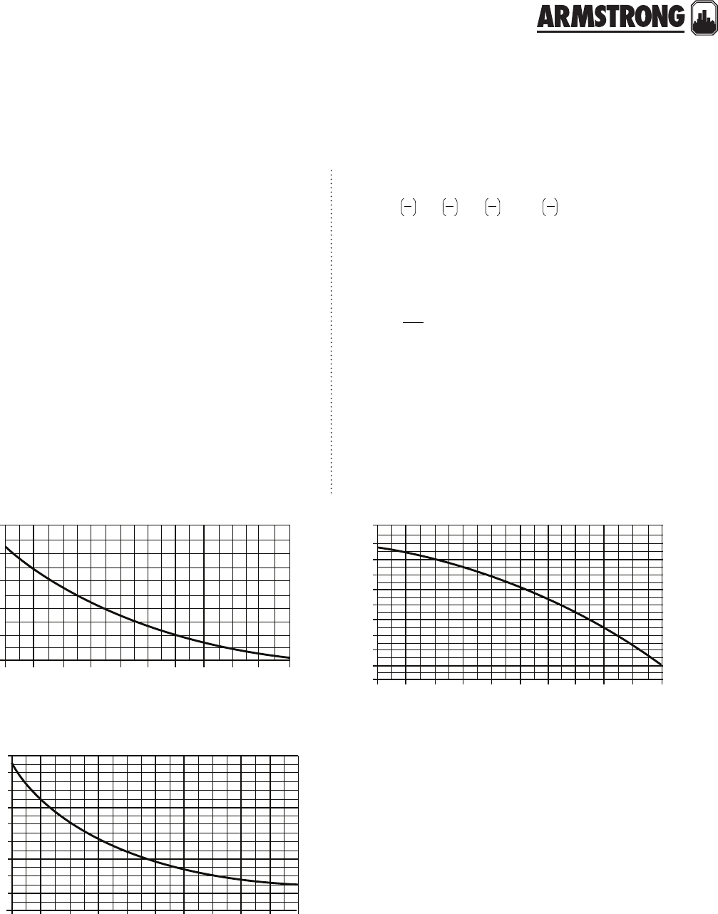
TECHNICAL DATA
191
|
HYDRONIC SOLUTIONS CATALOG
hydraulic resistance
equivalent resistance
r = (αcL)
therefore:
HL= r (f)1.75 = (αcL) (f)1.75
where:
HL = Head loss across a device due to viscous friction (ft of
head)
α = fluid properties factor based on the fluid’s density and
viscosity
c = constant based on the size of the tube
L = length of pipe, or equivalent length of a piping device (ft)
f = flow rate of fluid through the component (gpm)
Hydraulic Resistance of Series - connected Components
rseries = Σri = (r1+r2+r3+r4+....+rn)
Hydraulic Resistance of Parallel - connected Components
r parallel =
[ ]
the fluid properties factor (α)
where:
α = fluid properties factor
D = density of the fluid (1 lb/ft3 )
μ = dynamic viscosity of the fluid ( 1lb/ft/sec )
50
0.04
0.045
0.05
0.055
0.06
0.065
70 90 110 130 150 170 190 210 230
250
alpha value of water
water temperature (°f)
Graph of
α
- value of water for temperature of 50°f to 250°f
50 70 90 110 130 150 170 190 210 230 250
58
58.5
59.5
50.5
51.5
62.5
59
60
61
62
63
density of water (lb/cubic ft.)
water temperature (°f)
The density of water as a function of temperature
50 70 90 110 130 150 170 190 210 230
250
0.0009
0.0008
0.0007
0.0006
0.0005
0.0004
0.0003
0.0002
0.0001
0
dynamic viscosity (lb/cubic ft.)
water temperature (°f)
Dynamic viscosity of water as a function of temperature
0.5714
n
0.5714
3
0.5714
2
0.5714
r
1
r
1
r
1
r
1
1
++++ ...
( )
-0.25
μ
D
=
α
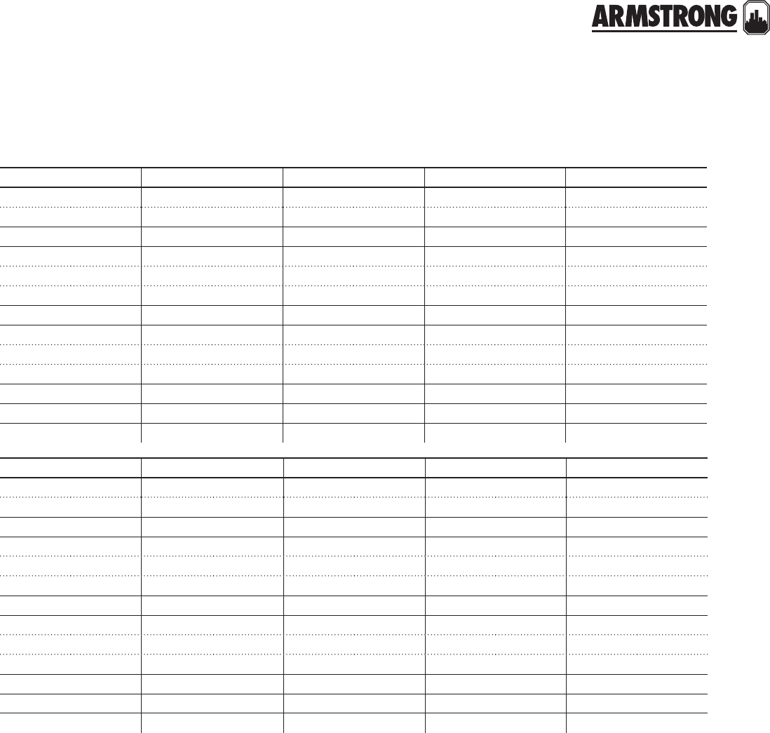
TECHNICAL DATA
192
|
HYDRONIC SOLUTIONS CATALOG
pipe information sheet - steel
W" K" X" O" 1"
sch 40- sch 40- sch 40- sch 40- sch 40-
od: 0.675 od: 0.840 od: -od: 1.050 od: 1.315
id: 0.493 id: 0.622 id: -id: 0.824 id: 1.049
c value: 0.78765 c value: 0.25984 c value: -c value: 0.07471 c value: 0.02436
sch 80- sch 80- sch 80- sch 80- sch 80-
od: 0.675 od: 0.840 od: -od: 1.050 od: 1.315
id: 0.423 id: 0.546 id: -id: 0.742 id: 0.957
c value: 1.70607 c value: 0.48964 c value: -c value: 0.12618 c value: 0.03855
sch 160- sch 160- sch 160- sch 160- sch 160-
od: -od: 0.840 od: -od: 1.050 od: 1.315
id: -id: 0.464 id: -id: 0.614 id: 0.815
c value: -c value: 0.87174 c value: -c value: 0.33293 c value: 0.08658
Flow range, gpm: 0-2.8 Flow range, gpm: 0-10 Flow range, gpm: Flow range, gpm: 0-20 Flow range, gpm: 0-45
1¼" 1K" 2" 2K" 3"
sch 40- sch 40- sch 40- sch 40- sch 40-
od: 1.660 od: 1.900 od: 2.375 od: 2.875 od: 3.500
id: 1.380 id: 1.610 id: 2.067 id: 2.469 id: 3.068
c value: 0.00557 c value: 0.00257 c value: 0.00077 c value: 0.00033 c value: 0.00012
sch 80- sch 80- sch 80- sch 80- sch 80-
od: 1.660 od: 1.900 od: 2.375 od: 2.875 od: 3.500
id: 1.278 id: 1.500 id: 1.939 id: 2.323 id: 2.900
c value: 0.00813 c value: 0.00363 c value: 0.00105 c value: 0.00105 c value: 0.00016
sch 160- sch 160- sch 160- sch 160- sch 160-
od: 1.660 od: 1.900 od: 2.375 od: 2.875 od: 3.500
id: 1.160 id: 1.338 id: 1.689 id: 2.125 id: 2.626
c value: 0.01316 c value: 0.00635 c value: 0.00206 c value: 0.00069 c value: 0.00026
Flow range, gpm: 0-90 Flow range, gpm: 0-180 Flow range, gpm: 0-300 Flow range, gpm: 0-500 Flow range, gpm: 0-650

TECHNICAL DATA
193
|
HYDRONIC SOLUTIONS CATALOG
pipe information sheet - copper
W" K" X" O" 1"
type k- type k- type k- type k- type k-
od: 0.402 od: 0.527 od: 0.652 od: 1.05 od: 0.995
id: 0.049 id: 0.049 id: 0.049 id: 0.824 id: 0.065
c value: 1.77376 c value: 0.48633 c value: 0.17587 c value: 0.07471 c value: 0.02363
type l- type l- type l- type l- type l-
od: 0.43 od: 0.545 od: 0.666 od: 1.05 od: 1.025
id: 0.035 id: 0.04 id: 0.042 id: 0.742 id: 0.05
c value: 1.26336 c value: 0.41416 c value: 0.15898 c value: 0.12618 c value: 0.0205
type m- type m- type m- type m- type m-
od: 0.45 od: 0.569 od: 0.69 od: 1.05 od: 1.055
id: 0.025 id: 0.028 id: 0.03 id: 0.614 id: 0.035
c value: 1.03958 c value: 0.3371 c value: 0.12715 c value: 0.33293 c value: 0.01788
s.p.s. pipe- s.p.s. pipe- s.p.s. pipe- s.p.s. pipe- s.p.s. pipe-
od: 0.494 od: 0.625 od: -od: 1.05 od: 1.062
id: 0.0905 id: 0.1075 id: -id: 0.614 id: 0.1265
c value: 0.66583 c value: 0.21583 c value: -c value: 0.33293 c value: 0.01733
Flow range, gpm: 0-5 Flow range, gpm: 0-10 Flow range, gpm: 0-13 Flow range, gpm: 0-18 Flow range, gpm: 0-50
1¼" 1K" 2" 2K" 3"
type k- type k- type k- type k- type k-
od: 1.245 od: 1.481 od: 1.959 od: 2.345 od: 2.907
id: 0.065 id: 0.072 id: 0.083 id: 0.095 id: 0.109
c value: 0.00819 c value: 0.00363 c value: 0.00095 c value: 0.00034 c value: 0.00015
type l- type l- type l- type l- type l-
od: 1.265 od: 1.505 od: 1.985 od: 2.465 od: 2.945
id: 0.055 id: 0.06 id: 0.07 id: 0.08 id: 0.09
c value: 0.00761 c value: 0.00336 c value: 0.00089 c value: 0.00032 c value: 0.00014
type m- type m- type m- type m- type m-
od: 1.219 od: 1.527 od: 2.009 od: 2.495 od: 2.981
id: 0.042 id: 0.049 id: 0.058 id: 0.065 id: 0.072
c value: 0.0069 c value: 0.00313 c value: 0.00084 c value: 0.00031 c value: 0.00013
s.p.s. pipe- s.p.s. pipe- s.p.s. pipe- s.p.s. pipe- s.p.s. pipe-
od: 1.368 od: 1.6 od: 2.062 od: 2.5 od: 3.062
id: 0.146 id: 0.15 id: 0.1565 id: 0.1875 id: 0.219
c value: 0.00523 c value: 0.00251 c value: 0.00074 c value: 0.0003 c value: 0.00012
Flow range, gpm: 0-100 Flow range, gpm: 0-130 Flow range, gpm: 0-300 Flow range, gpm: 0-500 Flow range, gpm: 0-800
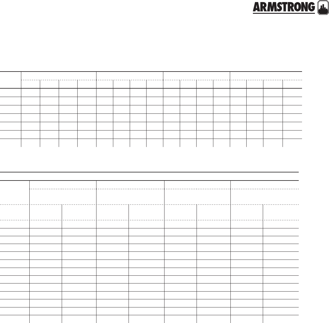
TECHNICAL DATA
194
|
HYDRONIC SOLUTIONS CATALOG
pressure drops (per 100ft/pipe at °f)
friction of water (smooth wall copper tubing, brass, and plastic pipe)
flow
(gpm)
W" heat-pex® K" heat-pex® X" heat-pex® O" heat-pex®
100° 120° 140° 160° 100° 120° 140° 160° 100° 120° 140° 160° 100° 120° 140° 160°
0.25 1.31 1.28 1.23 1.2 0.31 0.3 0.29 0.28 0.12 0.11 0.1 0.1 0.06 0.06 0.057 0.054
0.5 4.57 4.27 4.12 4.02 1.03 0.99 0.95 0.93 0.39 0.37 0.36 0.35 0.2 0.19 0.19 0.18
0.75 9.43 8.94 8.64 8.43 2.14 2.05 1.98 1.93 0.81 0.77 0.75 0.73 0.42 0.4 0.39 0.38
115.7 15.01 14.51 14.15 3.6 3.44 3.33 3.25 1.35 1.29 1.24 1.21 0.69 0.66 0.64 0.62
1.25 23.33 22.3 21.56 20.04 5.37 5.14 4.96 4.84 2.01 1.92 1.86 1.81 1.04 0.99 0.96 0.93
1.5 32.2 30.8 29.77 29.05 7.43 7.1 6.86 6.69 2.78 2.66 2.57 2.5 - - - -
1.75 42.57 40.61 39.26 38.31 9.82 9.34 9.07 8.85 3.67 3.51 3.39 3.31 1.89 1.81 1.74 1.7
W inch
type k tubing type l tubing type m tubing pipe *
.402" inside diameter
.049" wall thickness
.430" inside diameter
.035" wall thickness
.450" inside diameter
.025" wall thickness
.494" inside diameter
.0905" wall thickness
flow
(usgpm)
velocity
(ft./sec.)
head loss
(ft./100ft.)
velocity
(ft./sec.)
head loss
(ft./100ft.)
velocity
(ft./sec.)
head loss
(ft./100ft.)
velocity
(ft./sec.)
head loss
(ft./100ft.)
0.2 0.51 0.55 0.44 0.48 0.4 0.39 0.34 0.26
0.4 1.01 2.15 0.88 1.57 0.81 1.27 0.67 0.82
0.6 1.52 4.29 1.33 3.12 1.21 2.52 11.63
0.8 2.02 7.02 1.77 5.11 1.61 4.12 1.34 2.66
12.52 10.32 2.2 7.5 2.01 6.05 1.68 3.89
1.5 3.78 20.66 3.3 15.5 3.02 12.21 2.51 7.84
25.04 34.48 4.4 20.03 4.02 20.16 3.35 12.94
2.5 6.3 51.03 5.5 37.01 5.03 29.8 4.19 19.11
37.55 70.38 6.6 51.02 6.04 41.07 5.02 26.32
3.5 8.82 92.44 7.7 66.98 7.04 53.9 5.86 34.52
410.1 117.1 8.8 84.85 8.05 68.26 6.7 43.7
4.5 11.4 144.4 9.9 104.6 9.05 84.11 7.53 53.82
512.6 174.3 11 126.1 10.05 101.4 8.36 64.87
notes:
*s.p.s. copper and brass pipe.
No allowance has been made for age, dierence in diameter, or any abnormal condition of the interior surface. Any factor of safety must be estimated from the local
conditions and the requirements of each particular installation. It is recommended that for most commercial design purposes a safety factor of 15 to 20% he added to
the values in the tables.
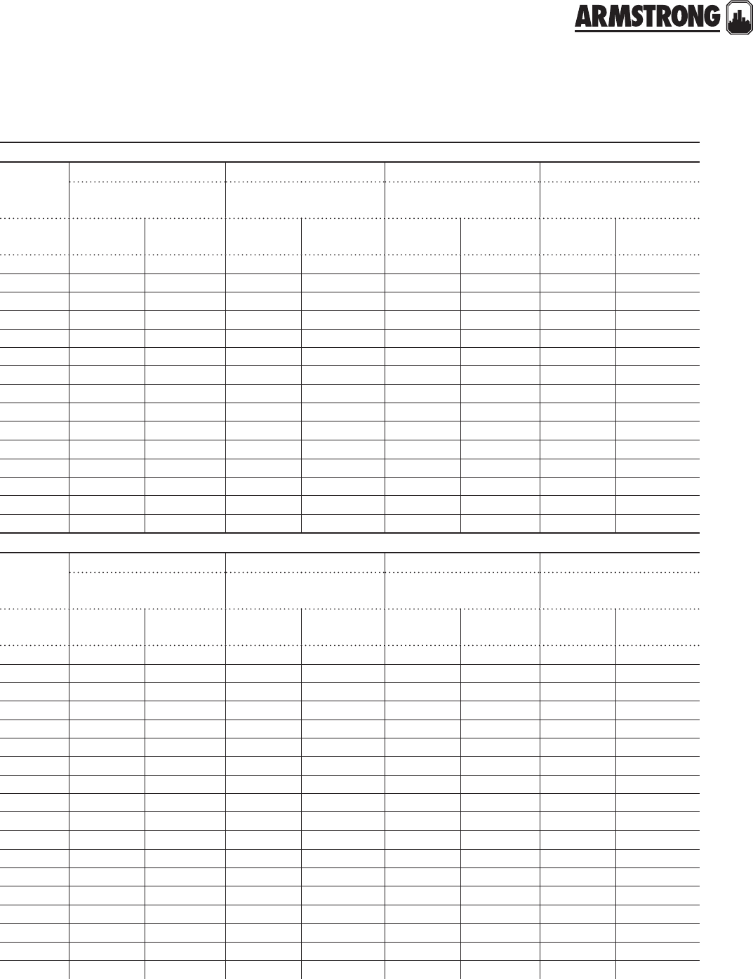
TECHNICAL DATA
195
|
HYDRONIC SOLUTIONS CATALOG
K inch
type k tubing type l tubing type m tubing pipe *
.527" inside diameter
.049" wall thickness
.545" inside diameter
.040" wall thickness
.569" inside diameter
.028" wall thickness
.625" inside diameter
.1075" wall thickness
flow
(usgpm)
velocity
(ft./sec.)
head loss
(ft./100ft.)
velocity
(ft./sec.)
head loss
(ft./100ft.)
velocity
(ft./sec.)
head loss
(ft./100ft.)
velocity
(ft./sec.)
head loss
(ft./100ft.)
½0.74 0.88 0.69 0.75 0.63 0.62 0.52 0.4
11.47 2.87 1.38 2.45 1.26 21.04 1.28
1½ 2.2 5.77 2.06 4.93 1.9 4.02 1.57 2.58
22.94 9.52 2.75 8.11 2.53 6.61 2.09 4.24
2½ 3.67 14.05 3.44 11.98 3.16 9.76 2.61 6.25
34.4 19.34 4.12 16.48 3.79 13.42 3.13 8.59
3½ 5.14 25.36 4.81 21.61 4.42 17.59 3.66 11.25
45.87 32.09 5.5 27.33 5.05 22.25 4.18 14.22
4½ 6.61 39.51 6.19 33.65 5.68 27.39 4.7 17.5
57.35 47.61 6.87 40.52 6.31 32.99 5.22 21.07
68.81 65.79 8.25 56.02 7.59 45.57 6.26 29.09
710.3 86.57 9.62 73.69 8.84 59.93 7.31 38.23
811.8 109.9 11 93.5 10.1 76.03 8.35 48.47
913.2 135.6 12.4 115.4 11.4 93.82 9.4 59.79
10 14.7 163.8 13.8 139.4 12.6 113.3 10.4 72.16
O inch
type k tubing type l tubing type m tubing pipe *
.745" inside diameter
.065" wall thickness
.785" inside diameter
.045" wall thickness
.811" inside diameter
.032" wall thickness
.822" inside diameter
.114" wall thickness
flow
(usgpm)
velocity
(ft./sec.)
head loss
(ft./100ft.)
velocity
(ft./sec.)
head loss
(ft./100ft.)
velocity
(ft./sec.)
head loss
(ft./100ft.)
velocity
(ft./sec.)
head loss
(ft./100ft.)
10.74 0.56 0.66 0.44 0.62 0.38 0.6 0.35
21.47 1.84 1.33 1.44 1.24 1.23 1.21 1.16
32.21 3.73 1.99 2.91 1.86 2.49 1.81 2.34
42.94 6.16 2.65 4.81 2.48 4.12 2.42 3.86
53.67 9.12 3.31 7.11 3.1 6.09 3.02 5.71
64.41 12.57 3.98 9.8 3.72 8.39 3.62 7.86
75.14 16.51 4.64 12.86 4.34 11.01 4.23 10.32
85.88 20.91 5.3 16.28 4.96 13.94 4.83 13.07
96.61 25.77 5.96 20.06 5.59 17.17 5.44 16.1
10 7.35 31.08 6.62 24.19 6.2 20.7 6.04 19.41
11 8.09 36.83 7.29 28.66 6.82 24.52 6.64 22.99
12 8.83 43.01 7.95 33.47 7.44 28.63 7.25 26.84
13 9.56 49.62 8.61 38.61 8.06 33.02 7.85 30.96
14 10.3 56.66 9.27 44.07 8.68 37.69 8.45 35.33
15 11 64.11 9.94 49.86 9.3 42.64 9.05 39.97
16 11.8 71.97 10.6 55.97 9.92 47.86 9.65 44.86
17 12.5 80.24 11.25 62.39 10.55 53.35 10.25 50
18 13.2 88.92 11.92 69.13 11.17 59.1 10.85 55.4
notes:
*s.p.s. copper and brass pipe.
No allowance has been made for age, dierence in diameter, or any abnormal condition of the interior surface. Any factor of safety must be estimated from the local
conditions and the requirements of each particular installation. It is recommended that for most commercial design purposes a safety factor of 15 to 20% he added to
the values in the tables.
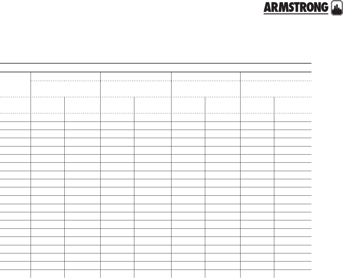
TECHNICAL DATA
196
|
HYDRONIC SOLUTIONS CATALOG
1 inch
type k tubing type l tubing type m tubing pipe *
.995" inside diameter
.065" wall thickness
1.025" inside diameter
.050" wall thickness
1.055" inside diameter
.035" wall thickness
1.062" inside diameter
.1265" wall thickness
flow
(usgpm)
velocity
(ft./sec.)
head loss
(ft./100ft.)
velocity
(ft./sec.)
head loss
(ft./100ft.)
velocity
(ft./sec.)
head loss
(ft./100ft.)
velocity
(ft./sec.)
head loss
(ft./100ft.)
20.82 0.47 0.78 0.41 0.73 0.36 0.72 0.35
31.24 0.95 1.17 0.82 1.1 0.72 1.08 0.7
41.65 1.56 1.56 1.35 1.47 1.18 1.45 1.14
52.06 2.3 1.95 21.83 1.74 1.81 1.69
62.48 3.17 2.34 2.75 2.2 2.4 2.17 2.32
72.89 4.15 2.72 3.6 2.56 3.14 2.53 3.04
83.3 5.25 3.11 4.56 2.93 3.97 2.89 3.85
93.71 6.47 3.5 5.61 3.3 4.89 3.25 4.74
10 4.12 7.79 3.89 6.76 3.66 5.89 3.61 5.71
12 4.95 10.76 4.67 9.33 4.4 8.13 4.34 7.88
14 5.77 14.15 5.45 12.27 5.13 10.69 5.05 10.36
16 6.6 17.94 6.22 15.56 5.86 13.55 5.78 13.13
18 7.42 22.14 719.2 6.6 16.72 6.5 16.2
20 8.24 26.73 7.78 23.18 7.33 20.18 7.22 19.55
25 10.3 39.87 9.74 34.56 9.16 30.09 9.03 29.15
30 12.37 55.33 11.68 47.96 11 41.74 10.84 40.43
35 14.42 73.06 13.61 63.31 12.82 55.09 12.65 53.37
40 16.5 93 15.55 80.58 14.66 70.11 14.45 67.9
45 18.55 115.1 17.5 99.72 16.5 86.75 16.25 84.2
50 20.6 139.4 19.45 120.7 18.32 105 18.05 101.7
notes:
*s.p.s. copper and brass pipe.
No allowance has been made for age, dierence in diameter, or any abnormal condition of the interior surface. Any factor of safety must be estimated from the local
conditions and the requirements of each particular installation. It is recommended that for most commercial design purposes a safety factor of 15 to 20% he added to
the values in the tables.

TECHNICAL DATA
197
|
HYDRONIC SOLUTIONS CATALOG
1N inch
type k tubing type l tubing type m tubing pipe *
1.245" inside diameter
.065" wall thickness
1.265" inside diameter
.055" wall thickness
1.291" inside diameter
.042" wall thickness
1.368" inside diameter
.146" wall thickness
flow
(usgpm)
velocity
(ft./sec.)
head loss
(ft./100ft.)
velocity
(ft./sec.)
head loss
(ft./100ft.)
velocity
(ft./sec.)
head loss
(ft./100ft.)
velocity
(ft./sec.)
head loss
(ft./100ft.)
51.31 0.79 1.28 0.74 1.22 0.67 1.09 0.51
61.58 1.09 1.53 1.01 1.47 0.92 1.31 0.7
71.84 1.43 1.79 1.32 1.71 1.2 1.53 0.91
82.11 1.81 2.04 1.67 1.96 1.52 1.75 1.15
92.37 2.22 2.3 2.06 2.2 1.87 1.96 1.42
10 2.63 2.67 2.55 2.48 2.45 2.25 2.18 1.71
12 3.16 3.69 3.06 3.42 2.93 3.1 2.62 2.35
15 3.95 5.47 3.83 5.07 3.66 4.6 3.27 3.49
20 5.26 9.13 5.1 8.46 4.89 7.67 4.36 5.81
25 6.58 13.59 6.38 12.59 6.11 11.42 5.46 8.65
30 7.9 18.83 7.65 17.44 7.33 15.82 6.55 11.98
35 9.21 24.83 8.94 23 8.55 20.86 7.65 15.79
40 10.5 31.57 10.2 29.24 9.77 26.51 8.74 20.06
45 11.8 38.03 11.5 36.15 11 32.77 9.83 24.8
50 13.2 47.2 12.8 43.71 12.2 39.63 10.9 29.98
60 15.8 65.65 15.3 60.78 14.7 55.1 13.1 41.66
70 18.4 86.82 17.9 80.38 17.1 72.86 15.3 55.07
80 21.1 110.7 20.4 102.5 19.6 92.85 17.5 70.16
90 23.7 137.25 23 127 22 115.1 19.6 86.91
100 26.3 166.3 25.5 153.9 24.4 139.4 21.8 105.3
notes:
*s.p.s. copper and brass pipe.
No allowance has been made for age, dierence in diameter, or any abnormal condition of the interior surface. Any factor of safety must be estimated from the local
conditions and the requirements of each particular installation. It is recommended that for most commercial design purposes a safety factor of 15 to 20% he added to
the values in the tables.

TECHNICAL DATA
198
|
HYDRONIC SOLUTIONS CATALOG
1K inch
type k tubing type l tubing type m tubing pipe *
1.481" inside diameter
.072" wall thickness
1.505" inside diameter
.060" wall thickness
1.527" inside diameter
.049" wall thickness
1.600" inside diameter
.150" wall thickness
flow
(usgpm)
velocity
(ft./sec.)
head loss
(ft./100ft.)
velocity
(ft./sec.)
head loss
(ft./100ft.)
velocity
(ft./sec.)
head loss
(ft./100ft.)
velocity
(ft./sec.)
head loss
(ft./100ft.)
81.49 0.79 1.44 0.73 1.4 0.68 1.27 0.55
91.67 0.97 1.62 0.9 1.57 0.84 1.43 0.67
10 1.86 1.17 1.8 1.08 1.75 1.01 1.59 0.81
12 2.23 1.61 2.16 1.49 2.1 1.39 1.91 1.12
15 2.79 2.39 2.7 2.21 2.63 2.07 2.39 1.65
20 3.72 3.98 3.6 3.68 3.5 3.44 3.19 2.75
25 4.65 5.91 4.51 5.48 4.38 5.11 3.98 4.09
30 5.58 8.19 5.41 7.58 5.25 7.07 4.78 5.65
35 6.51 10.79 6.31 9.99 6.13 9.31 5.58 7.45
40 7.44 13.7 7.21 12.68 711.83 6.37 9.45
45 8.37 16.93 8.11 15.67 7.88 14.61 7.16 11.68
50 9.3 20.46 9.01 18.94 8.76 17.66 7.96 14.11
60 11.2 28.42 10.8 26.3 10.5 24.53 9.56 19.59
70 13 37.55 12.6 34.74 12.3 32.4 11.2 25.87
80 14.9 47.82 14.4 44.24 14 41.25 12.8 32.93
90 16.7 59.21 16.2 54.78 15.8 51.07 14.4 40.76
100 18.6 71.7 18 66.34 17.5 61.84 15.9 49.34
110 20.5 85.29 19.8 78.9 19.3 73.55 17.5 58.67
120 22.3 99.95 21.6 92.46 21 86.18 19.1 68.74
130 24.2 115.7 23.4 107 22.8 99.73 20.7 79.53
notes:
*s.p.s. copper and brass pipe.
No allowance has been made for age, dierence in diameter, or any abnormal condition of the interior surface. Any factor of safety must be estimated from the local
conditions and the requirements of each particular installation. It is recommended that for most commercial design purposes a safety factor of 15 to 20% he added to
the values in the tables.

TECHNICAL DATA
199
|
HYDRONIC SOLUTIONS CATALOG
2 inch
type k tubing type l tubing type m tubing pipe *
1.959" inside diameter
.083" wall thickness
1.985" inside diameter
.070" wall thickness
2.009" inside diameter
.058" wall thickness
2.062" inside diameter
.1565" wall thickness
flow
(usgpm)
velocity
(ft./sec.)
head loss
(ft./100ft.)
velocity
(ft./sec.)
head loss
(ft./100ft.)
velocity
(ft./sec.)
head loss
(ft./100ft.)
velocity
(ft./sec.)
head loss
(ft./100ft.)
10 1.07 0.31 1.04 0.29 1.01 0.27 0.96 0.24
12 1.28 0.43 1.24 0.4 1.21 0.38 1.15 0.33
14 1.49 0.56 1.45 0.52 1.42 0.5 1.34 0.44
16 1.7 0.71 1.66 0.66 1.62 0.63 1.53 0.55
18 1.92 0.87 1.87 0.82 1.82 0.77 1.72 0.68
20 2.13 1.05 2.07 0.98 2.02 0.93 1.92 0.82
25 2.66 1.55 2.59 1.46 2.53 1.38 2.39 1.22
30 3.19 2.15 3.11 2.01 3.03 1.9 2.87 1.68
35 3.73 2.82 3.62 2.65 3.54 2.5 3.35 2.21
40 4.26 3.58 4.14 3.36 4.05 3.17 3.83 2.8
45 4.79 4.42 4.66 4.15 4.55 3.92 4.3 3.46
50 5.32 5.43 5.17 5.01 5.05 4.73 4.8 4.17
60 6.39 7.4 6.21 6.95 6.06 6.56 5.75 5.79
70 7.45 9.76 7.25 9.16 7.07 8.65 6.7 7.63
80 8.52 12.42 8.28 11.65 8.09 11 7.65 9.7
90 9.58 15.36 9.31 14.41 9.1 13.6 8.61 12
100 10.65 18.58 10.4 17.43 10.1 16.45 9.57 14.51
110 11.71 22.07 11.4 20.71 11.1 19.55 10.5 17.24
120 12.78 25.84 12.4 24.25 12.1 22.88 11.5 20.18
130 13.85 29.88 13.4 28.04 13.1 26.45 12.5 23.33
140 14.9 34.18 14.5 32.07 14.2 30.26 13.4 26.69
150 16 38.75 15.5 36.36 15.2 34.3 14.4 30.25
160 17 43.58 16.5 40.89 16.2 38.58 15.3 34.01
170 18.1 48.67 17.6 45.66 17.2 43.08 16.3 37.98
180 19.2 54.01 18.6 50.67 18.2 47.81 17.2 42.15
190 20.2 59.61 19.6 55.92 19.2 52.76 18.2 46.51
200 21.3 65.46 20.7 61.41 20.2 57.94 19.2 51.07
210 22.4 71.57 21.7 67.14 21.2 63.34 20.1 55.83
220 23.4 77.93 22.8 73.1 22.2 68.96 21 60.78
230 24.5 84.53 23.8 79.29 23.2 74.8 22 65.93
240 25.6 91.38 24.8 85.72 24.3 80.86 23 71.26
250 26.6 98.43 25.9 92.37 25.3 87.14 23.9 76.79
260 27.7 105.8 26.9 99.26 26.3 93.63 24.9 82.51
270 28.8 113.4 27.9 106.4 27.3 100.3 25.8 88.42
280 29.8 121.3 29 113.7 28.3 107.3 26.8 94.52
290 30.9 129.3 30 121.3 29.4 114.3 27.8 100.8
300 32 137.6 31.1 129.1 30.4 121.8 28.7 107.3
notes:
*s.p.s. copper and brass pipe.
No allowance has been made for age, dierence in diameter, or any abnormal condition of the interior surface. Any factor of safety must be estimated from the local
conditions and the requirements of each particular installation. It is recommended that for most commercial design purposes a safety factor of 15 to 20% he added to
the values in the tables.

TECHNICAL DATA
200
|
HYDRONIC SOLUTIONS CATALOG
2K inch
type k tubing type l tubing type m tubing pipe *
2.435" inside diameter
.095" wall thickness
2.465" inside diameter
.080" wall thickness
2.495" inside diameter
.065" wall thickness
2.500" inside diameter
.1875" wall thickness
flow
(usgpm)
velocity
(ft./sec.)
head loss
(ft./100ft.)
velocity
(ft./sec.)
head loss
(ft./100ft.)
velocity
(ft./sec.)
head loss
(ft./100ft.)
velocity
(ft./sec.)
head loss
(ft./100ft.)
20 1.38 0.37 1.34 0.35 1.31 0.33 1.31 0.33
25 1.72 0.55 1.68 0.52 1.64 0.49 1.63 0.49
30 2.07 0.76 2.02 0.72 1.97 0.68 1.96 0.67
35 2.41 12.35 0.94 2.3 0.89 2.29 0.88
40 2.76 1.26 2.69 1.19 2.62 1.13 2.61 1.12
45 3.1 1.56 3.02 1.47 2.95 1.39 2.94 1.38
50 3.45 1.88 3.36 1.77 3.28 1.68 3.26 1.66
60 4.14 2.61 4.03 2.46 3.93 2.32 3.92 2.3
70 4.82 3.43 4.7 3.24 4.59 3.06 4.57 3.03
80 5.51 4.36 5.37 4.12 5.25 3.88 5.22 3.85
90 6.2 5.39 6.04 5.08 5.9 4.8 5.88 4.75
100 6.89 6.52 6.71 6.15 6.55 5.8 6.53 5.74
110 7.58 7.74 7.38 7.3 7.21 6.89 7.19 6.82
120 8.27 9.06 8.05 8.54 7.86 8.05 7.84 7.81
130 8.96 10.46 8.73 9.87 8.52 9.31 8.49 9.22
140 9.65 11.97 9.4 11.28 9.18 10.64 9.14 10.54
150 10.35 13.56 10.1 12.78 9.83 12.06 9.79 11.94
160 11 15.24 10.8 14.36 10.5 13.55 10.45 13.42
170 11.7 17.01 11.4 16.03 11.1 15.12 11.1 14.98
180 12.4 18.87 12.1 17.79 11.8 16.78 11.8 16.61
190 13.1 20.81 12.8 19.62 12.5 18.51 12.4 18.33
200 13.8 22.85 13.4 21.54 13.1 20.31 13.1 20.12
220 15.2 27.18 14.8 25.61 14.4 24.16 14.4 23.93
240 16.5 31.84 16.1 30.01 15.7 28.31 15.7 28.03
260 17.9 36.85 17.5 34.73 17.1 32.75 17 32.44
280 19.3 42.19 18.8 39.76 18.4 37.5 18.3 37.13
300 20.7 47.86 20.1 45.1 19.7 42.53 19.6 42.12
320 22.1 53.86 21.5 50.75 21 47.86 20.9 47.4
340 23.4 60.18 22.8 56.71 22.3 53.48 22.2 52.96
360 24.8 66.83 24.2 62.97 23.6 59.38 23.5 58.81
380 26.2 73.8 25.5 69.54 24.9 65.57 24.8 64.94
400 27.6 81.09 26.9 76.41 26.2 72.04 26.1 47.81
420 29 88.7 28.2 83.57 27.5 78.8 28.49 78.04
440 30.3 96.62 29.5 91.04 28.8 85.83 28.7 85
460 31.7 104.9 30.9 98.8 30.2 93.15 30 92.24
480 33.1 113.4 32.2 106.8 31.5 100.7 31.4 99.76
500 34.5 122.3 33.6 115.2 32.8 108.6 32.6 107.5
notes:
*s.p.s. copper and brass pipe.
No allowance has been made for age, dierence in diameter, or any abnormal condition of the interior surface. Any factor of safety must be estimated from the local
conditions and the requirements of each particular installation. It is recommended that for most commercial design purposes a safety factor of 15 to 20% he added to
the values in the tables.

TECHNICAL DATA
201
|
HYDRONIC SOLUTIONS CATALOG
3 inch
type k tubing type l tubing type m tubing pipe *
2.907" inside diameter
.109" wall thickness
2.945" inside diameter
.090" wall thickness
2.981" inside diameter
.072" wall thickness
3.062" inside diameter
.2195" wall thickness
flow
(usgpm)
velocity
(ft./sec.)
head loss
(ft./100ft.)
velocity
(ft./sec.)
head loss
(ft./100ft.)
velocity
(ft./sec.)
head loss
(ft./100ft.)
velocity
(ft./sec.)
head loss
(ft./100ft.)
20 0.96 0.16 0.94 0.15 0.92 0.14 0.87 0.13
30 1.45 0.33 1.41 0.31 1.37 0.29 1.3 0.25
40 1.93 0.54 1.88 0.51 1.83 0.48 1.74 0.42
50 2.41 0.81 2.35 0.76 2.29 0.72 2.17 0.63
60 2.89 1.12 2.82 1.05 2.75 0.99 2.61 0.87
70 3.38 1.47 3.29 1.38 3.2 1.3 3.04 1.15
80 3.86 1.87 3.76 1.75 3.66 1.65 3.48 1.45
90 4.34 2.3 4.23 2.16 4.12 2.04 3.91 1.8
100 4.82 2.78 4.7 2.61 4.59 2.47 4.35 2.17
110 5.3 3.3 5.17 3.1 5.05 2.93 4.79 2.57
120 5.79 3.86 5.64 3.63 5.5 3.42 5.21 3.01
130 6.27 4.46 6.11 4.19 5.95 3.95 5.65 3.47
140 6.75 5.1 6.58 4.79 6.41 4.52 6.09 3.97
150 7.24 5.77 7.05 5.42 6.87 5.12 6.52 4.5
160 7.72 6.49 7.52 6.09 7.34 5.75 6.95 5.05
170 8.2 7.24 7.99 6.8 7.79 6.41 7.39 5.64
180 8.69 8.03 8.46 7.54 8.25 7.11 7.82 6.25
190 9.16 8.85 8.93 8.32 8.7 7.84 8.25 6.89
200 9.64 9.71 9.40 9.13 9.16 8.61 8.70 7.56
220 10.60 11.55 10.30 10.85 10.10 10.23 956 8.99
240 11.60 13.52 11.30 12.70 11.00 11.98 10.40 10.52
260 12.60 15.64 12.20 14.69 11.90 13.85 11.30 12.17
280 13.50 17.90 13.20 16.81 12.80 15.85 12.20 13.93
300 14.50 20.30 14.10 19.06 13.70 17.97 13.00 15.79
320 15.40 22.83 15.00 21.44 14.70 20.22 13.90 17.76
340 16.40 25.50 16.00 23.95 15.60 22.58 14.80 19.83
360 17.40 28.30 16.90 26.95 16.50 25.06 15.70 22.01
380 18.30 31.24 17.90 29.58 17.40 27.66 16.50 24.29
400 19.30 34.32 18.80 32.22 18.30 30.38 17.40 26.68
450 21.70 42.58 21.20 39.98 20.60 37.69 19.60 33.09
500 24.10 51.65 23.50 48.50 22.90 45.72 21.70 40.14
550 26.60 61.54 25.80 57.77 25.20 54.46 23.90 47.81
600 29.00 72.22 28.20 67.80 27.50 63.91 26.10 56.10
650 31.40 83.69 3060 78.56 29.80 74.05 28.20 65.00
700 33.80 95.95 32.90 90.06 32.10 84.89 30.40 74.50
750 36.20 109.00 35.20 102.30 34.40 96.41 32.60 84.61
800 38.60 122.80 37.60 115.30 36.60 108.60 34.80 95.31
notes:
*s.p.s. copper and brass pipe.
No allowance has been made for age, dierence in diameter, or any abnormal condition of the interior surface. Any factor of safety must be estimated from the local
conditions and the requirements of each particular installation. It is recommended that for most commercial design purposes a safety factor of 15 to 20% he added to
the values in the tables.

TECHNICAL DATA
202
|
HYDRONIC SOLUTIONS CATALOG
3K inch
type k tubing type l tubing type m tubing pipe *
3.385" inside diameter
.120" wall thickness
3.425" inside diameter
.100" wall thickness
3.459" inside diameter
.083" wall thickness
3.500" inside diameter
.250" wall thickness
flow
(usgpm)
velocity
(ft./sec.)
head loss
(ft./100ft.)
velocity
(ft./sec.)
head loss
(ft./100ft.)
velocity
(ft./sec.)
head loss
(ft./100ft.)
velocity
(ft./sec.)
head loss
(ft./100ft.)
60 2.14 0.54 2.09 0.51 2.05 0.49 2.00 0.46
70 2.49 0.71 2.44 0.67 2.39 0.64 2.33 0.60
80 2.84 0.90 2.78 0.85 2.73 0.81 2.66 0.77
90 3.20 1.11 3.13 1.05 3.07 1.00 3.00 0.95
100 3.56 1.34 3.48 1.27 3.41 1.21 3.33 1.14
110 3.92 1.59 382 1.50 3.76 1.43 3.67 1.35
120 4.26 1.86 4.18 1.76 4.10 1.68 4.00 1.58
130 4.62 2.15 4.52 2.03 4.45 1.93 433 1.83
140 4.98 2.45 4.87 2.32 4.79 2.21 4.66 2.09
150 5.34 2.78 5.21 2.62 5.12 2.50 5.00 2.36
160 5.69 3.12 5.56 2.95 5.46 2.81 5.33 2.66
170 6.05 3.48 5.91 3.29 5.80 3.14 5.66 2.96
180 6.40 3.86 6.26 3.64 6.16 3.48 6.00 3.28
190 6.76 4.25 6.60 4.02 6.49 3.83 6.33 3.62
200 7.11 4.67 695 4.41 6.82 4.20 6.66 3.97
220 7.82 5.54 7.65 5.24 7.51 4.99 7.33 4.72
240 8.54 6.49 8.35 6.13 8.19 5.85 8.00 5.52
260 9.25 7.50 9.05 7.09 8.87 6.76 8.66 6.39
280 9.95 8.58 9.74 8.11 9.55 7.73 9.33 7.30
300 10.70 9.73 10.40 9.19 10.20 8.76 10.00 8.28
350 12.50 12.87 12.20 12.16 11.90 11.60 11.70 10.95
400 14.20 16.42 13.90 15.51 13.70 14.79 13.30 13.97
450 16.00 20.36 15.60 19.23 15.40 18.33 15.00 17.32
500 17.80 24.68 17.40 23.32 17.10 22.23 16.70 20.99
550 19.60 29.39 19.10 27.76 18.80 26.46 18.30 24.99
600 21.40 34.47 20.90 32.56 20.50 31.04 20.00 29.31
650 23.10 39.92 22.60 37.71 22.20 35.94 21.60 33.95
700 24.90 45.75 24.40 43.21 23.90 41.18 23.30 38.89
750 26.60 51.94 26.10 49.05 25.60 46.75 25.00 44.15
800 28.40 58.49 27.80 55.24 27.30 52.65 26.60 49.75
850 30.20 65.40 29.60 61.77 29.00 58.87 28.30 55.59
900 32.00 72.68 31.30 68.63 30.70 65.41 30.00 61.77
950 33.80 80.31 33.00 75.84 32.40 72.27 31.60 68.24
1000 35.60 88.29 34.80 83.37 34.10 79.46 33.30 75.02
1100 39.20 105.30 38.20 99.45 37.60 94.77 36.70 89.47
1200 42.60 123.70 41.80 116.80 41.00 111.30 40.00 105.10
1300 46.20 143.50 45.20 135.50 44.50 129.10 43.30 121.90
1400 49.80 164.70 48.70 155.50 47.90 148.20 46.60 139.90
notes:
*s.p.s. copper and brass pipe.
No allowance has been made for age, dierence in diameter, or any abnormal condition of the interior surface. Any factor of safety must be estimated from the local
conditions and the requirements of each particular installation. It is recommended that for most commercial design purposes a safety factor of 15 to 20% he added to
the values in the tables.

TECHNICAL DATA
203
|
HYDRONIC SOLUTIONS CATALOG
4 inch
type k tubing type l tubing type m tubing pipe *
3.857" inside diameter
.134" wall thickness
3.905" inside diameter
.110" wall thickness
3.935" inside diameter
.095" wall thickness
4.000" inside diameter
.250" wall thickness
flow
(usgpm)
velocity
(ft./sec.)
head loss
(ft./100ft.)
velocity
(ft./sec.)
head loss
(ft./100ft.)
velocity
(ft./sec.)
head loss
(ft./100ft.)
velocity
(ft./sec.)
head loss
(ft./100ft.)
100 2.74 0.72 2.68 0.68 2.64 0.65 2.55 0.60
110 3.02 0.85 2.94 0.80 2.90 0.77 2.81 0.71
120 329 0.99 3.21 0.94 3.16 0.90 3.06 0.83
130 3.57 1.15 3.48 1.08 3.42 1.04 3.31 0.96
140 3.84 1.31 3.74 1.23 3.69 1.19 3.57 1.10
150 4.11 1.48 4.01 1.40 395 1.35 3.83 1.25
160 4.39 1.67 4.28 1.57 4.21 1.51 4.08 1.39
170 4.66 1.86 4.55 1.75 4.48 1.69 4.33 1.56
180 4.94 2.06 4.81 1.94 4.74 1.87 4.58 1.73
190 521 2.27 5.08 2.14 5.00 2.06 4.84 1.91
200 5.49 2.49 5.35 2.35 5.27 2.26 5.10 2.09
220 6.04 2.96 589 2.79 5.80 2.68 5.61 2.48
240 6.59 3.46 6.42 3.26 6.32 3.14 6.12 2.90
260 7.14 4.00 695 3.77 6.85 3.63 6.63 3.36
280 7.69 4.57 7.49 4.31 7.38 4.15 7.14 3.84
300 8.24 5.18 8.02 4.88 7.90 4.70 7.65 4.35
350 960 6.85 9.36 6.46 9.22 6.22 8.92 5.75
400 11.00 8.74 10.70 8.23 10.50 7.93 10.20 7.33
450 12.40 10.83 12.00 10.20 11.90 9.83 11.50 9.08
500 13.70 13.12 13.40 12.36 13.20 11.91 12.80 11.00
550 15.1 15.61 14.70 14.71 14.50 14.17 14.10 13.09
600 16.5 18.31 16.00 17.24 15.80 16.61 15.30 15.35
650 17.9 21.19 17.40 19.96 17.10 19.23 16.60 17.77
700 19.2 24.28 18.70 22.86 18.40 22.03 17.90 20.35
750 20.6 27.55 20.10 25.95 19.80 25.00 19.10 23.09
800 22.0 31.01 21.40 29.21 21.10 28.14 20.40 25.99
850 23.30 34.67 22.80 32.65 22.40 31.46 21.70 29.05
900 24.7 38.51 24.10 36.27 23.70 34.94 23.00 32.27
950 26.1 42.54 25.40 40.06 25.00 38.60 24.20 35.64
1000 27.4 46.76 26.80 44.03 26.40 42.42 25.50 39.17
1100 30.2 55.74 29.40 52.48 29.00 50.56 28.10 46.69
1200 32.9 65.45 32.10 61.62 31.60 59.37 30.60 54.82
1300 35.70 75.89 34.80 71.45 34.20 68.83 33.10 63.55
1400 38.40 87.05 37.40 81.95 36.90 78.95 35.70 72.89
1500 41.10 98.23 40.10 93.13 39.50 89.71 38.30 82.82
1600 43.90 111.50 42.80 105.00 42.10 101.10 40.80 93.34
1800 49.40 138.80 48.10 130.60 47.40 125.80 45.80 116.10
2000 54.90 168.90 53.50 158.90 52.70 153.10 51.00 141.30
2200 60.40 201.70 58.90 189.80 58.00 182.80 56.10 168.70
notes:
*s.p.s. copper and brass pipe.
No allowance has been made for age, dierence in diameter, or any abnormal condition of the interior surface. Any factor of safety must be estimated from the local
conditions and the requirements of each particular installation. It is recommended that for most commercial design purposes a safety factor of 15 to 20% he added to
the values in the tables.

TECHNICAL DATA
204
|
HYDRONIC SOLUTIONS CATALOG
friction of water (new steel pipe)
K inch
standard weight steel - sch. 40 extra strong steel - sch. 80
.622" inside diameter .546" inside diameter
flow
(usgpm)
velocity
(ft./sec.)
velocity
(head ft.)
head loss
(ft./100ft.)
velocity
(ft./sec.)
velocity
(head ft.)
head loss
(ft./100ft.)
0.7 0.739 .008 0.74 0.96 .01 1.39
1.0 1.056 .017 1.86 1.37 .03 2.58
1.5 1.58 .039 2.82 2.06 .07 5.34
2.0 2.11 .069 4.73 2.74 .12 9.02
2.5 2.64 .108 7.10 3.43 .18 13.60
3.0 3.17 .156 9.94 4.11 .26 19.10
3.5 3.70 .212 13.20 4.80 .36 25.50
4.0 4.22 .277 17.00 5.48 .47 32.70
4.5 4.75 .351 21.10 6.17 .59 40.90
5.0 5.28 .433 25.80 6.86 .73 50.00
5.5 5.81 .524 30.90 7.54 .88 59.90
6.0 6.34 .624 36.40 8.23 1.05 70.70
6.5 6.86 .732 42.40 8.91 1.23 82.40
7.0 7.39 .849 48.80 9.60 1.43 95.00
7.5 7.92 .975 55.60 10.30 1.60 109.00
80 8.45 1.109 63.00 11.00 1.90 123.00
8.5 8.98 1.25 70.70 11.60 2.10 138.00
9.0 9.50 1.40 78.90 12.30 2.40 154.00
9.5 10.03 1.56 87.60 13.00 260 171.00
10.0 10.56 1.73 96.60 13.70 2.90 189.00
O inch
standard weight steel - sch. 40 extra strong steel - sch. 80
.824" inside diameter .742" inside diameter
flow
(usgpm)
velocity
(ft./sec.)
velocity
(head ft.)
head loss
(ft./100ft.)
velocity
(ft./sec.)
velocity
(head ft.)
head loss
(ft./100ft.)
1.5 0.90 .013 0.72 1.11 .02 1.19
2.0 1.20 .023 1.19 1.48 .03 1.99
2.5 1.50 .035 1.78 1.86 .05 2.97
3.0 1.81 .051 2.47 2.23 .08 4.14
3.5 2.11 .069 3.26 2.60 .11 5.48
4.0 2.41 .090 4.16 2.97 .14 7.01
4.5 2.71 .114 5.17 3.34 .17 8.72
5.0 3.01 .141 6.28 3.71 .21 10.60
6.0 3.61 .203 8.80 4.45 .31 14.90
7.0 4.21 .276 11.70 5.20 .42 19.90
8.0 4.81 .360 15.10 5.94 .55 25.60
9.0 5.42 .456 18.80 6.68 .69 32.10
10.0 6.02 .563 23.00 7.42 .86 39.20
11.0 6.62 .681 27.60 8.17 1.04 47.00
12.0 7.22 .722 32.50 8.91 1.23 55.50
13.0 7.82 .951 37.90 9.63 1.44 64.80
14.0 8.42 1.103 43.70 10.40 1.70 74.70
16.0 9.63 1.44 56.40 11.90 2.20 96.70
18.0 10.80 1.82 70.80 13.40 2.80 121.00
20.0 12.00 2.25 86.80 14.80 3.40 149.00
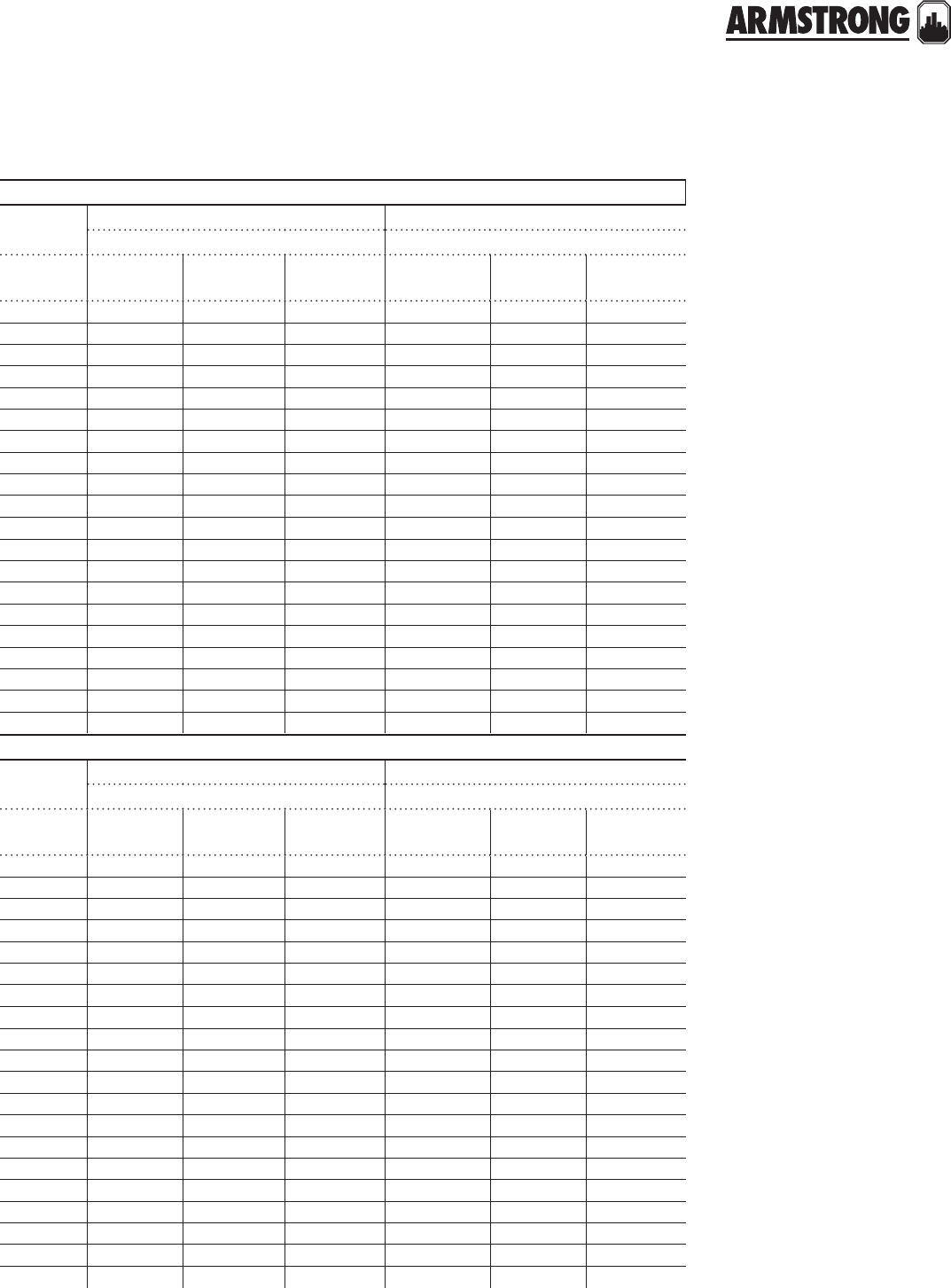
TECHNICAL DATA
205
|
HYDRONIC SOLUTIONS CATALOG
1 inch
standard weight steel - sch. 40 extra strong steel - sch. 80
1.049" inside diameter .957" inside diameter
flow
(usgpm)
velocity
(ft./sec.)
velocity
(head ft.)
head loss
(ft./100ft.)
velocity
(ft./sec.)
velocity
(head ft.)
head loss
(ft./100ft.)
20.74 .009 .385 0.89 01 .599
31.11 019 .787 1.34 .03 1.19
41.48 .034 1.270 1.79 .05 1.99
51.86 .054 1.90 2.23 .08 2.99
62.23 .077 2.65 2.68 .11 4.17
82.97 .137 4.50 3.57 .20 7.11
10 3.71 .214 6.81 4.46 .31 10.80
12 4.45 .308 9.58 5.36 .45 15.20
14 5.20 .420 12.80 6.25 .61 20.40
16 5.94 .548 16.50 7.14 .79 26.30
18 6.68 .694 20.60 8.03 1.00 32.90
20 7.42 .857 25.20 8.92 1.24 40.30
22 8.17 1.036 30.30 9.82 1.50 48.40
24 8.91 1.23 35.80 10.70 1.80 57.20
26 9.65 1.45 41.70 11.60 2.10 66.80
28 10.39 1.68 48.10 12.50 2.40 77.10
30 1 1 .10 1.93 55.00 13.40 2.80 88.20
35 13.00 2.62 74.10 15.60 380 119.00
40 14.80 3.43 96.10 17.90 500 154.00
45 16.70 4.33 121.00 20.10 6.30 194.00
1N inch
standard weight steel - sch. 40 extra strong steel - sch. 80
1.380" inside diameter 1.278" inside diameter
flow
(usgpm)
velocity
(ft./sec.)
velocity
(head ft.)
head loss
(ft./100ft.)
velocity
(ft./sec.)
velocity
(head ft.)
head loss
(ft./100ft.)
4.858 .011 .35 1.00 .015 .51
51.073 .018 .52 1.25 .024 .75
61.29 .026 .72 1.50 .034 1.04
71.50 .035 .95 1.75 .048 1.33
81.72 .046 1.20 2.00 .062 1.69
10 2.15 .072 1.74 2.50 .097 2.55
12 2.57 .103 2.45 3.00 .140 3.57
14 3.00 .140 3.24 3.50 .190 4.75
16 3.43 .183 4.15 4.00 .249 6.10
18 3.86 .232 5.17 4.50 .315 7.61
20 4.29 .286 6.31 5.00 .388 9.28
25 536 .431 9.61 6.25 .607 14.20
30 6.44 .644 13.60 7.50 .874 20.10
35 7.51 .876 18.20 8.75 1.19 27.00
40 8.58 1.14 23.50 10.00 1.55 34.90
50 10.70 1.79 36.20 12.50 2.43 53.70
60 12.90 2.57 51.50 15.00 3.50 76.50
70 15.00 3.50 69.50 17.50 4.76 103.00
80 17.20 4.53 90.20 20.00 6.21 134.00
90 19.30 5.79 114.00 22.50 7.86 168.00

TECHNICAL DATA
206
|
HYDRONIC SOLUTIONS CATALOG
1K inch
standard weight steel - sch. 40 extra strong steel - sch. 80
1.610" inside diameter 1.500" inside diameter
flow
(usgpm)
velocity
(ft./sec.)
velocity
(head ft.)
head loss
(ft./100ft.)
velocity
(ft./sec.)
velocity
(head ft.)
head loss
(ft./100ft.)
4.63 .006 .166 .73 .01 .233
5.79 .010 .246 .91 .01 .346
6.95 .014 .340 1.09 .02 .478
71.10 .019 .447 1.27 .03 .630
81.26 .025 .567 1.45 .03 .800
91.42 .031 .701 1.63 .04 .990
10 1.58 .039 .848 1.82 .05 1.20
12 1.89 .056 1.18 2.18 .07 1.61
14 2.21 .076 1.51 2.54 .10 2.14
16 2.52 .099 1.93 2.90 .13 2.74
18 2.84 .125 2.40 3.27 .17 3.41
20 3.15 .154 2.92 3.63 .20 4.15
22 3.47 .187 3.48 3.99 .25 4.96
24 3.78 .222 4.10 4.36 .30 5.84
26 4.10 .261 4.76 4.72 .35 6.80
28 4.41 .303 5.47 5.08 .40 7.82
30 4.73 .347 6.23 5.45 .46 8.91
32 5.04 .395 7.04 5.81 .52 10.10
34 5.36 .446 7.90 6.17 .59 11.30
36 5.67 .500 8.80 6.54 .66 12.60
38 5.99 .577 9.76 6.90 .74 14.00
40 6.30 .618 10.80 7.26 .82 15.40
42 6.62 .681 11.80 7.63 .90 16.90
44 6.93 .747 12.90 7.99 .99 18.50
46 7.25 .817 14.00 8.35 1.08 20.10
48 7.56 .889 15.20 8.72 1.18 21.80
50 7.88 .965 16.50 9.08 1.28 23.60
55 8.67 1.17 19.80 9.99 1.55 28.40
60 9.46 1.39 23.40 10.90 1.80 33.60
65 10.24 1.63 27.30 11.80 2.20 39.20
70 11.03 1.89 31.50 12.70 2.50 45.30
75 11.80 2.17 36.00 13.60 2.90 51.80
80 12.60 2.47 40.80 14.50 3.30 58.70
85 13.40 2.79 45.90 15.40 3.70 66.00
90 14.20 3.13 51.30 16.30 4.10 73.80
95 15.00 3.48 57.00 17.20 4.60 82.00
100 15.80 3.86 63.00 18.20 5.10 90.70
110 17.30 4.67 75.80 20.00 6.20 109.30
120 18.90 5.56 89.90 21.80 7.40 129.60
130 20.50 6.52 105.00 23.60 8.70 151.60
140 22.10 7.56 122.00 25.40 10.00 175.0
150 23.60 8.68 139.00 27.20 11.50 201.0
160 25.20 9.88 158.00 29.00 13.10 228.0
170 26.80 11.15 178.00 30.90 14.80 257.0
180 28.40 12.50 199.00 32.70 16.60 288.0

TECHNICAL DATA
207
|
HYDRONIC SOLUTIONS CATALOG
2 inch
standard weight steel - sch. 40 extra strong steel - sch. 80
2.067" inside diameter 1.939" inside diameter
flow
(usgpm)
velocity
(ft./sec.)
velocity
(head ft.)
head loss
(ft./100ft.)
velocity
(ft./sec.)
velocity
(head ft.)
head loss
(ft./100ft.)
5.478 .004 .074 .54 .00 .101
6.574 .005 .102 .65 .01 .139
7.669 .007 .134 .76 .01 .182
8.765 .009 .170 .87 .01 .231
9.860 .012 .209 .98 .01 .285
10 .956 .014 .252 1.09 .02 .343
12 1.15 .021 .349 1.30 .03 .476
14 1.34 .028 .461 1.52 .04 .628
16 1.53 .036 .586 1.74 .05 .800
18 1.72 .046 .725 1.96 ,06 .991
20 1.91 .057 .878 2.17 .07 1.16
22 2.10 .069 1.05 2.39 .09 1.38
24 2.29 .082 1.18 2.61 .11 1.62
26 2.49 .096 1.37 2.83 .12 1.88
28 2.68 .111 1.57 304 .14 2.16
30 2.87 .128 1.82 3.26 .17 2.46
35 3.35 .174 2.38 3.80 .22 3.28
40 3.82 .227 3.06 4.35 .29 4.21
45 4.30 .288 3.82 4.89 .37 5.26
50 4.78 .355 4.66 5.43 .46 6.42
55 5.26 .430 5.58 5.98 .56 7.70
60 5.74 .511 6.58 6.52 .66 9.09
65 6.21 .600 7.66 706 .77 10.59
70 6.69 .696 8.82 7.61 .90 12.20
75 7.17 .799 10.10 8.15 1.03 13.90
80 7,65 .909 11.40 8.69 1.17 15.80
85 8.13 103 12.80 9.03 1.27 17.70
90 8.60 115 14.30 9.78 1.49 19.80
95 9.08 1.28 15.90 10.30 1.60 22.00
100 9.56 1.42 17.50 10.90 1.80 24.30
110 10.52 1.72 21.00 12.00 2.20 29.20
120 11.50 2.05 24.90 13.00 2.60 34.50
130 12.40 2.40 29.10 14,10 3.10 40.30
140 13.40 2.78 33.60 15.20 3.60 46.60
150 14.30 3.20 38.40 16.30 4.10 53.30
160 15.30 3.64 43.50 17.40 4.70 60.50
170 16.30 4.11 49.00 18.50 5.30 68.10
180 17.20 4.60 54.80 19.60 6.00 76.10
190 18.20 5.13 60.90 20.60 6.60 84.60
200 19.10 5.68 67.30 21.70 7.30 93.60
220 21.00 6.88 81.10 23.90 8.90 113.0
240 22.90 8.18 96.20 26.90 10,60 134.0
260 24.90 9.60 113.0 28.30 12.40 157.0
280 26.80 11.14 130.0 30.40 14.40 181.0
300 28.70 12.80 149.0 32.60 16.50 208.0

TECHNICAL DATA
208
|
HYDRONIC SOLUTIONS CATALOG
2K inch
standard weight steel - sch. 40 extra strong steel - sch. 80
2.469" inside diameter 2.323" inside diameter
flow
(usgpm)
velocity
(ft./sec.)
velocity
(head ft.)
head loss
(ft./100ft.)
velocity
(ft./sec.)
velocity
(head ft.)
head loss
(ft./100ft.)
8.536 .005 .072 .61 .01 .097
10 .670 .007 .107 .76 .01 .144
12 .804 .010 .148 .91 .01 .199
14 .938 .014 .195 1.06 .02 .261
16 1.07 .018 .247 1.21 .02 .332
18 1.21 .023 .305 1.36 .03 .411
20 1.34 .028 .369 1.51 .04 .497
22 1.47 .034 .438 1.67 .04 .590
24 1.61 .040 .513 1.82 .05 .691
26 1.74 .047 .593 1.97 .06 0.800
28 1.88 .055 .679 2.12 .07 0.915
30 2.01 .063 .770 2.27 .08 1.00
35 2.35 .086 .99 2.65 .11 1.33
40 2.68 .112 1.26 3.03 .14 1.71
45 3.02 .141 1.57 3.41 .18 2.13
50 3.35 .174 1.91 3.79 .22 2.59
55 3.69 .211 2.28 4.16 .27 3.10
60 4.02 .251 2.69 4.54 .32 3.65
65 4.36 .295 3.13 4.92 .38 4.25
70 4.69 .342 3.60 5.30 .44 4.89
75 5.03 .393 4.10 5.68 .50 5.58
80 5.36 .447 4.64 6.05 .57 6.31
85 5.70 .504 5.20 6.43 .64 7.08
90 6.03 .565 5.80 6.81 .72 7.89
95 6.37 .630 6.43 7.19 0.80 8.76
100 6.70 .698 7.09 7.57 0.89 9.66
110 7.37 .844 8.51 8.33 1.08 11.60
120 8.04 1.00 10.10 9.08 1.28 13.70
130 8.71 118 11.70 9.84 1.50 16.00
140 9.38 1.37 13.50 10.60 1.70 18.50
150 10.05 1.57 15.50 11.30 2.00 21.10
160 10.70 1.79 17.50 12.10 2.30 23.90
170 11.40 2.02 19.70 12.90 2.60 26.90
180 12.10 2.26 22.00 13.60 2.90 30.10
190 12.70 2.52 24.40 14.40 3.20 33.40
200 13.40 2.79 27.00 15.10 3.50 36.90
220 14.70 3.38 32.50 16.70 4.30 44.40
240 16.10 402 38.50 18.20 5.10 52.70
260 17.40 4.72 45.00 19.70 6.00 61.60
280 18.80 5.47 52.30 21.20 7.00 71.20
300 20.10 6.28 59.60 22.70 8.00 81.60
350 23.50 8.55 80.60 26.50 10.90 110.0
400 26.80 11.20 105.0 30.30 14.30 144.0
450 30.20 14.20 132.0 34.10 18.10 181.0
500 33.50 17.40 163.0 37.90 22.30 223.0

TECHNICAL DATA
209
|
HYDRONIC SOLUTIONS CATALOG
3 inch
standard weight steel - sch. 40 extra strong steel - sch. 80
3.068" inside diameter 2.900" inside diameter
flow
(usgpm)
velocity
(ft./sec.)
velocity
(head ft.)
head loss
(ft./100ft.)
velocity
(ft./sec.)
velocity
(head ft.)
head loss
(ft./100ft.)
10 .434 .003 .038 .49 .00 .050
15 .651 .007 .077 .73 .01 .101
20 .868 .012 .129 .97 .02 .169
25 1.09 .018 .192 1.21 .02 .253
30 1.30 .026 .267 1.45 .03 .351
35 1.52 .036 .353 1.70 .04 .464
40 1.74 .047 .449 1.94 .06 .592
45 1.95 .059 .557 2.18 .07 .734
50 2.17 .073 .676 2.43 .09 .860
55 2.39 ,089 .776 2.67 .11 1.03
60 2.60 .105 . .912 2.91 .13 1.21
65 2.82 .124 1.06 3.16 .15 1.40
70 3.04 .143 1.22 3.40 .18 1.61
75 3.25 .165 1.38 3.64 .21 1.83
80 3.47 .187 1.56 3,88 .23 2.07
85 3.69 .211 1.75 4,12 .26 2.31
90 3.91 .237 1.95 4.37 .29 2.58
95 4.12 .264 2.16 4.61 .33 2.86
100 4,34 .293 2.37 4.85 .36 3.15
110 4.77 .354 2.84 5.33 .44 3.77
120 5.21 .421 3.35 5.81 .52 4.45
130 5.64 .495 3.90 6.30 .62 5.19
140 6.08 ,574 4.50 6.79 ,71 5.98
150 6.51 .659 5.13 7.28 .82 6.82
160 6.94 .749 5.80 7,76 .93 7.72
180 7.81 .948 7.27 8.72 101 9.68
200 8,68 1.17 8.90 9,70 1.46 11.86
220 9.55 1.42 10.70 10.70 1.78 14.26
240 10.40 1.69 12.70 11.60 2.07 16.88
260 11.30 1.98 14.80 12.60 2.46 19.71
280 12.20 2.29 17.10 13.60 2.88 22.77
300 13.00 2.63 19.50 14.50 3.26 26.04
320 13.90 3.00 22.10 15.50 3.77 29.53
340 14,80 3.38 24.90 16.50 4.22 33.24
360 15.60 3.79 27.80 17.50 4.73 37.16
380 16.50 4.23 30.90 18.40 5.27 41.31
400 17.40 4.68 34.20 19.40 5.81 45.67
420 18.20 5.16 37.60 20.40 6.43 50.25
440 19.10 5.67 41.20 21.40 7.13 55.05
460 20.00 6.19 44.90 22.30 7.75 60.06
480 20.80 6.74 48.80 23.30 8.37 65.30
500 21.70 7.32 52.90 24.20 9.15 70.75
550 23.90 8.85 63.80 26.70 11.10 85.33
600 26.00 10.50 75.70 29.10 13.10 101.00
650 28.20 12.40 88.60 31.60 15.50 119.00

TECHNICAL DATA
210
|
HYDRONIC SOLUTIONS CATALOG
3K inch
standard weight steel - sch. 40 extra strong steel - sch. 80
3.548" inside diameter 3.364" inside diameter
flow
(usgpm)
velocity
(ft./sec.)
velocity
(head ft.)
head loss
(ft./100ft.)
velocity
(ft./sec.)
velocity
(head ft.)
head loss
(ft./100ft.)
15 .487 .004 .038 .54 .00 .050
20 .649 .007 .064 .72 .01 .083
25 .811 .010 .095 .90 .01 .123
30 .974 .015 .132 1.08 .02 .171
35 1.14 .020 .174 1.26 .02 .225
40 1.30 .026 .221 1.44 .03 .287
45 1.46 .033 .274 1.63 .04 .355
50 1.62 .041 .332 1.80 .05 .430
60 1.95 .059 .463 2.17 .07 .601
70 2.27 .080 .614 2.53 .10 .769
80 2.60 .105 .757 2.89 .13 .986
90 2.92 .133 .943 3.25 .16 1.23
100 3.25 .164 1.15 3.61 .20 1.50
110 3.57 .198 1.37 3.97 .24 1.79
120 3.89 .236 1.62 4.33 .29 2.11
130 4.22 .277 1.88 4.69 .34 2.46
140 4.54 .321 2.16 5.05 .40 2.83
150 4.87 .368 2.47 5.41 .45 3.22
160 5.19 .419 2.79 5.78 .52 3.64
170 5.52 .473 3.13 6.14 .59 4.09
180 5.84 .530 3.49 6.50 .66 4.56
190 6.17 .591 3.86 6.85 .73 5.06
200 6.49 .655 4.26 7.22 .81 5.58
220 7.14 .792 5.12 7.94 .98 6.70
240 7.79 .943 6.04 8.66 1.17 7.92
260 8.44 1 .11 7.05 9.38 1.37 9.24
280 9.09 1.28 8.13 10.10 1.60 10.66
300 9.74 1.47 9.29 10.80 1.80 12.20
320 10.40 1.68 10.50 11.50 2.10 13.80
340 11.00 1.89 11.80 12.30 2.40 15.50
360 11.70 2.12 13.20 13.00 2.60 17.40
380 12.30 2.36 14.70 13.70 2.90 19.30
400 13.00 2.62 16.20 14.40 3.20 21.30
420 13.60 2.89 17.80 15.20 3.60 23.40
440 14.30 3.17 19.50 15.90 3.90 25.70
460 14.90 3.46 21.30 16.60 4.30 28.00
480 15.60 3.77 23.10 17.30 4.70 30.40
500 16.20 4.09 25.10 18.10 5.10 32.90
550 17.80 4.95 30.20 19.90 6.20 39.70
600 19.50 5.89 35.80 21.70 7.30 47.10
650 21.10 6.91 41.90 23.50 8.60 55.10
700 22.70 8.02 48.40 25.30 9.40 63.70
750 24.30 9.20 55.40 27.10 11.40 73.00
800 26.00 10.50 62.90 28.90 13.00 82.90
850 27.60 11.80 70.90 30.70 14.60 93.40

TECHNICAL DATA
211
|
HYDRONIC SOLUTIONS CATALOG
4 inch
standard weight steel - sch. 40 extra strong steel - sch. 80
4.026" inside diameter 3.826" inside diameter
flow
(usgpm)
velocity
(ft./sec.)
velocity
(head ft.)
head loss
(ft./100ft.)
velocity
(ft./sec.)
velocity
(head ft.)
head loss
(ft./100ft.)
20 .504 .004 .035 .56 .00 .045
30 .756 .009 .072 .84 .01 .092
40 1.01 .016 .120 1.12 .02 .153
50 1.26 .025 .179 1.40 .03 .230
60 1.51 .036 .250 1.67 .04 .320
70 176 .048 .330 1.95 .06 .424
80 2.02 .063 .422 2.23 .08 .541
90 2.27 .080 .523 2.51 .10 .649
100 2.52 .099 .613 2.79 .12 .789
110 2.77 .119 .723 307 .15 .943
120 302 .142 .861 3.35 .17 1.11
130 3.28 .167 1.00 3.63 .20 1.29
140 3.53 .193 1.15 3.91 .24 1.48
150 3.78 .222 1.31 4.19 .27 1.69
160 4.03 .253 1.48 4.47 .31 1.91
170 4.28 .285 1.66 4.75 .35 2.14
180 4.54 .320 1.85 502 .39 2.38
190 4.79 .356 2.05 5.30 .44 2.64
200 5.04 .395 2.25 5.58 48 2.91
220 5.54 478 2.70 6.14 .59 3.49
240 6.05 .569 3.19 6.70 .70 4.13
260 6.55 .667 3.72 7.26 .82 4.81
280 7.06 .774 4.28 7.82 .95 5.54
300 7.56 .888 4.89 8.38 1.09 6.33
320 8.06 1.01 5.53 8.94 1.24 7.17
340 8.57 1.14 6.22 9.50 140 8.06
360 9.07 1.28 6.94 10.00 1.60 9.00
380 9.58 143 7.71 10.60 1.70 9.99
400 10.10 1.58 8.51 11.20 1.90 11.00
420 10.60 1.74 9.35 11.70 2.10 12.10
440 11.10 1.91 10.20 12.30 2.30 13.30
460 11.60 2.09 11.20 12.80 2.50 14.50
480 12.10 2.27 12.10 1340 2.80 15.70
500 12.60 247 13.10 14.00 3.00 17.00
550 13.90 2.99 15.80 15.30 3.60 20.50
600 15.10 3.55 18.70 16.70 4.30 24.30
650 1640 4.17 21.70 18.10 5.10 28.40
700 17.60 4.84 25.30 19.50 5.90 32.80
750 18.90 5.55 28.90 20.90 6.80 37.60
800 20.20 6.32 32.80 22.30 7.70 42.70
850 2140 7.13 37.00 23.70 8.70 48.10
900 22.70 8.00 41.40 25.10 9.80 53.80
950 23.90 8.91 46.00 26.50 10.90 59.80
1000 25.20 9.87 50.90 27.90 12.10 66.20
1100 27.70 11.90 61.40 30.70 14.60 79.80
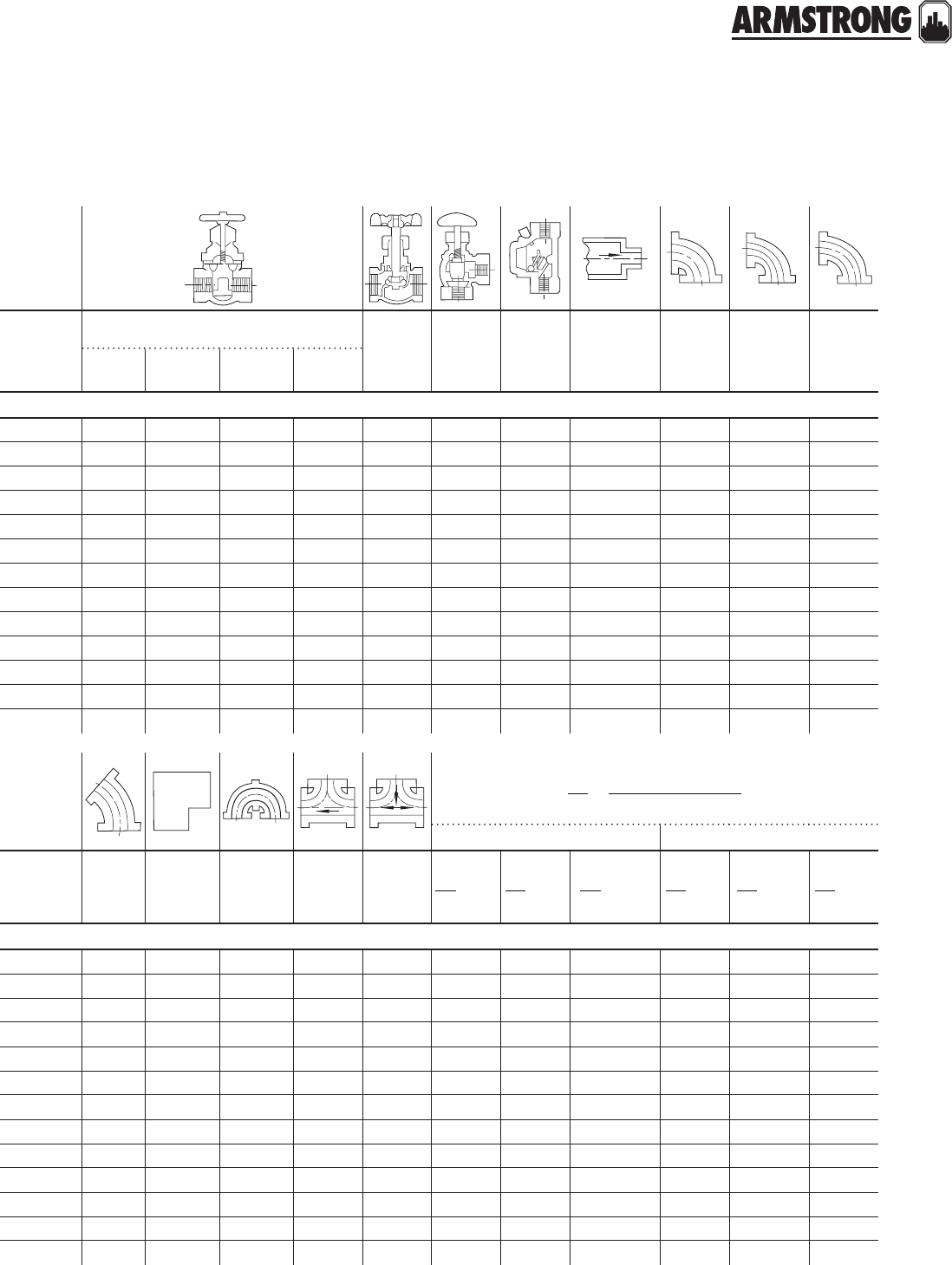
TECHNICAL DATA
212
|
HYDRONIC SOLUTIONS CATALOG
friction losses through pipe fittings & valves
size
of pipe
(inches)
gate valve globe
valve-
wide
open
angle
valve-
wide
open
check
valve-
wide
open
ordinary
entrance
to pipe
lines
std.
90°
elbow
medium
sweep
90°
elbow
long
sweep
9 0°
elbow
wide
open
¼
closed
½
closed
¾
closed
straight pipe in feet (equivalent length)
V0.14 0.85 5.00 19.00 9.00 5.00 2.00 0.46 0.74 0.65 0.50
N0.21 1.25 7.0 0 26.00 12.00 6.00 3.00 0.60 1.00 0.86 0.70
W0.27 1.80 9.00 36.00 16.00 8.00 4.00 0.75 1.40 1.15 0.90
K0.41 2.10 12.00 44.00 17.60 7.78 5.18 0.90 1.60 1.55 1.10
O0.55 2.90 14.00 59.00 23.30 10.30 6.86 1.40 2.30 2.06 1.50
1 0.70 3.40 18.00 70.00 29.70 13.10 8.74 1.60 2.70 2.62 2.00
1N 0.92 4.80 24.00 96.00 39.10 17.80 11.50 2.50 3.60 3.45 2.50
1K 1.07 5.60 28.00 116.00 45.60 20.10 13.40 3.00 4.50 4.03 2.90
21.38 7.00 36.00 146.00 58.60 25.80 17.20 3.50 5.40 5.17 3.60
2K 1.65 8.40 41.00 172.00 70.00 30.90 20.60 4.00 6.50 6.17 4.40
32.04 10.00 52.00 213.00 86.90 38.40 25.50 5.00 8.50 7.67 5.50
3K 2.10 12.50 60.00 246.00 1 00.00 52.00 24.00 5.50 10.0 8.50 6.30
42.40 14.00 70.00 285.00 116.00 57.0 0 27.00 6.50 12.0 9.50 7.20
use the smaller diameter in the column for pipe size
Larger diameter
Smaller diameter
D
d=
abrupt contraction abrupt enlargement
size
of pipe
(inches)
45°
elbow
square
90°
elbow
close
return
bends
std.
tee
std.
tee ¼ ½ ¾ ¼ ½ ¾
straight pipe in feet (equivalent length)
V0.40 1.60 2.00 0.50 1.60 0.40 0.30 0.16 0.74 0.46 0.16
N0.50 2.30 300 0.70 2.30 0.50 0.40 0.22 1.00 0.62 0.22
W0.65 3.00 4.00 0.90 3.00 0.65 0.50 0.29 1.40 0.83 0.29
K0.83 4.00 5.00 1.00 3.10 0.80 0.60 0.36 1.60 1.20 0.36
O1.10 500 600 1.40 4.10 1.00 0.80 0.48 2.30 1.40 0.48
1 1.40 6.00 700 1.80 5.30 1.50 100 0.62 2.70 1.60 0.62
1N 1.84 800 9.00 2.30 6.90 1.70 1.40 0.83 3.60 2.30 0.83
1K 2.15 9.50 11.00 2.70 8.10 2.00 1.60 0.97 4.50 2.70 0.97
22.76 13.00 14.00 3.50 10.30 2.50 2.00 1.30 5.40 3.50 1.30
2K 3.29 15.00 16.00 4.10 12.30 3.00 2.50 1.50 6.50 4.00 1.50
34.09 18.00 19.00 5.10 15.30 4.00 2.90 1.80 8.00 4.80 1.80
3K 4.50 20.00 2200 6.30 20.00 4.50 3.40 2.10 10.00 5.60 2.10
45.00 23.00 25.00 7. 20 23.00 500 4.00 2.40 12.00 6.40 2.40
D
d
D
d
D
d
D
d
D
d
D
d
note: V" to 4" are standard pipe sizes.

TECHNICAL DATA
213
|
HYDRONIC SOLUTIONS CATALOG
hydronic water flow calculator
(gallons per minute for btu/hr at various water temperature drops)
btu/hr
water temperature drop
btu/hr
water temperature drop
10°f 20°f 30°f 40°f 50°f 10°f 20°f 30°f 40°f 50°f
gpm gpm
101,000 20.2 10.1 6.7 5.1 4.0 151,000 30.2 15.1 10.1 7.6 6.0
102,000 20.4 10.2 6.8 5.1 4.1 152,000 30.4 15.2 10.1 7.6 6.1
103,000 20.6 10.3 6.9 5.2 4.1 153,000 30.6 15.3 10.2 7.7 6.1
104,000 20.8 10.4 6.9 5.2 4.2 154,000 30.8 15.4 10.3 7.7 6.2
105,000 21.0 10.5 7.0 5.3 4.2 155,000 31.0 15.5 10.3 7.8 6.2
106,000 21.2 10.6 7.1 5.3 4.2 156,000 31.2 15.6 10.4 7. 8 6.2
107,000 21.4 10.7 7.1 5.4 4.3 157,000 31.4 15.7 10.5 7.9 6.3
108,000 21.6 10.8 7.2 5.4 4.3 158,000 31.6 15.8 10.5 7.9 6.3
109,000 21.8 10.9 7. 3 5.5 4.4 159,000 31.8 15.9 10.6 8.0 6.4
110,000 22.0 11.0 7.3 5.5 4.4 160,000 32.0 16.0 10.7 8.0 6.4
111,000 22.2 11.1 7.4 5.6 4.4 161,000 32.2 16.1 10.7 8.1 6.4
112,000 22.4 11.2 7. 5 5.6 4.5 162.000 32.4 16.2 10.8 8.1 6.5
113,000 22.6 11.3 7.5 5.7 4.5 163,000 32.6 16.3 10.9 8.2 6.5
114,000 22.8 11.4 7.6 5.7 4.6 164,000 32.8 16.4 109 82 6.6
115,000 23.0 11.5 7.7 58 4.6 165,000 33.0 16.5 11.0 8.3 6.6
116,000 23.2 11.6 7.7 58 4.6 166,000 33.2 16.6 11.1 8.3 6.6
117,000 23.4 11.7 7.8 5.9 4.7 167,000 33.4 16.7 11 .1 8.4 6.7
118,000 23.6 11.8 7.9 59 4.7 168,000 33.6 16.8 11.2 8.4 6.7
119,000 23.8 11.9 7.9 6.0 4.8 169,000 33.8 16.9 11 .3 85 6.8
120,000 24.0 12.0 80 6.0 4.8 170,000 34.0 17.0 11 .3 8.5 6.8
121,000 24.2 12.1 8.1 6.1 4.8 171,000 34.2 17.1 11.4 8.6 6.8
122,000 24.4 12.2 81 6.1 4.9 172,000 34.4 17.2 11.5 8.6 6.9
123,000 24.6 12.3 8.2 6.2 4.9 173,000 34.6 17.3 11.5 8.7 6.9
124,000 24.8 12.4 8.3 6.2 5.0 174,000 34.8 17.4 11.6 8.7 7.0
125,000 25.0 12.5 8.3 6.3 5.0 175,000 35.0 17. 5 11.7 8.8 7.0
126,000 25.2 12.6 8.4 6.3 5.0 176,000 35.2 17.6 11.7 8.8 7.0
127,000 25.4 12.7 8.5 6.4 5.1 177,000 35.4 17.7 11.8 8.9 7.1
128,000 25.6 12.8 8.5 6.4 5.1 178,000 35.6 17.8 11 .9 8.9 7.1
129,000 25.8 12.9 8.6 6.5 5.2 179,000 358 17.9 11.9 90 7.2
130,000 26.0 13.0 8.7 6.5 5.2 180,000 36.0 18.0 12.0 9.0 7. 2
131,000 26.2 13.1 8.7 6.6 5.2 181,000 36.2 18.1 12.1 9.1 7.2
132,000 26.4 13.2 8.8 6.6 53 182,000 36.4 18.2 12.1 9.1 7.3
133,000 26.6 13.3 8.9 6.7 5.3 183,000 36.6 18.3 12.2 92 7.3
134,000 26.8 13.4 8.9 6.7 5.4 184,000 36.8 18.4 12.3 92 7.4
135,000 27.0 13.5 9.0 6.8 5.4 185,000 37.0 18.5 12.3 9.3 7.4
136,000 27.2 13.6 9.1 6.8 5.4 186,000 37.2 18.6 12.4 93 7.4
137,000 27.4 13.7 9.1 6.9 5.5 187,000 37.4 18.7 12.5 9.4 7.5
138,000 27.6 13.8 9.2 69 5.5 188,000 37.6 18.8 12.5 9.4 7.5
139,000 27.8 13.9 9.3 7.0 5.6 189,000 37.8 18.9 12.6 95 7.6
140,000 28.0 14.0 9.3 7.0 5.6 190,000 38.0 19.0 12.7 95 7.6
141,000 28.2 14.1 9.4 7.1 5.6 191,000 38.2 19.1 12.7 9.6 7.6
142,000 28.4 14.2 9.5 7.1 5.7 192,000 38.4 19.2 12.8 9.6 7.7
143,000 28.6 14.3 9.5 7.2 5.7 193,000 38.6 19.3 12.9 9.7 7.7
144,000 28.8 14.4 9.6 7.2 5.8 194,000 38.8 19.4 12.9 9.7 7.8
145,000 29.0 14.5 9.7 7.3 5.8 195,000 39.0 19.5 13.0 98 7.8
146,000 29.2 14.6 9.7 7. 3 58 196,000 39.2 19.6 13.1 98 7.8
147,000 29.4 14.7 9.8 7.4 5.9 197,000 39.4 19.7 13.1 9.9 7.9
148,000 29.6 14.8 9.9 7.4 5.9 198,000 39.6 19.8 13.2 9.9 7.9
149,000 29.8 14.9 9.9 7.5 6.0 199,000 39.8 19.9 13.3 10.0 8.0
150,000 30.0 15.0 10.0 7.5 6.0 200,000 40.0 20.0 13.3 10.0 8.0
notes: *S.P.S. copper and brass pipe.
No allowance has been made for age, dierence in diameter, or any abnormal condition of the interior surface. Any factor of safety must be estimated from the local
conditions and the requirements of each particular installation. It is recommended that for most commercial design purposes a safety factor of 15 to 20% he added to the
values in the tables.

TECHNICAL DATA
214
|
HYDRONIC SOLUTIONS CATALOG
conversions factors
conversions
1 U.S. Gallon = 231 Cubic Inches 1 Cubic Foot = 7.48 U.S. Gallons
= 0.1337 Cubic Feet = 0.0283 Cubic Meters
= 3.785 Liters 1 Liter = 0.264 U.S. Gallons
= 0.833 lmp. Gallons 1 Cubic Meter = 35.314 Cubic Feet
2 Imperial Gallon = 1.2 U.S. Gallons = 264.2 U.S. Gallons
= 999.97 Liters
to convert this to this multiply by
Q(m3/hr) gpm
Cubic meters per hour Gallons per minute Q(m3/hr) µ 4.4 =
Q(L/s) gpm
Liters per second Gallons per minute L/s µ 15.85 =
Q(L/min) gpm
Liters per minute Gallons per minute L/m µ 0.264 =
P(kW) hp
Kilowatts Horsepower kW µ 1.34 =
kW / 0.746 =
bar psi Absolute (psia)
Of pressure Pounds per square inch of pressure (includes atmospheric
pressure at sea level)
bar µ 14.5 + 14.7 =
bar psi Gauged (psig)
Of pressure Pounds per square inch of pressure as it would be read on a
pressure gauge (does not include atmospheric pressure)
bar µ 14.5 =
psig Head, Feet
Gauge pressure psi µ 2.31 / sp.gr. =
Millimeters Inches (mm) µ 0.0394 =
Meter Feet (meters) µ 3.28 =
Centimeters Inches centimeters µ 2.54 =
Nm (Newton meter) Ft. Ibs.
Measure of torque Foot pound of torque Nm µ 0.7376 =
°c °f
Degrees Celsius Degrees Fahrenheit °c (9/5) + 32 =
Watts Horsepower Watts µ 0.001341 =
Watts Btu/hr
British thermal units per hour Watts µ 3.4127 =
Boiler Horsepower Btu/hr Boiler Hp µ 33479 =
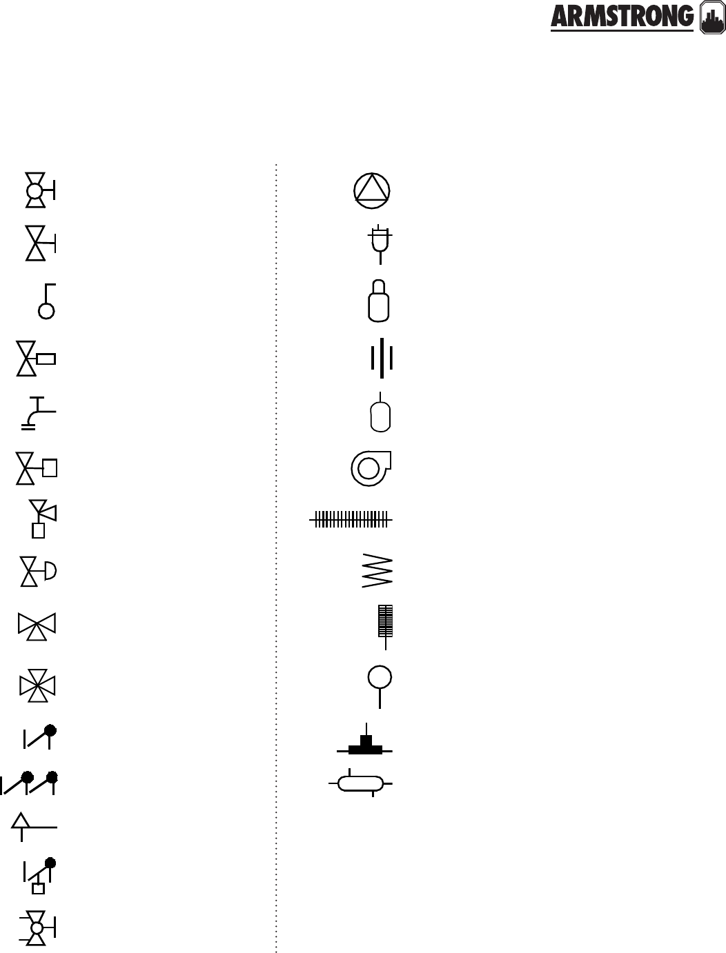
TECHNICAL DATA
215
|
HYDRONIC SOLUTIONS CATALOG
typical symbols
Globe valve Circulator pump
Gate valve Float-type vent
Ball valve Spirovent air separator
Thermostatic radiator valve (trv) Union
Drain I fill valve Expansion tank
Electronic zone valve Blower
Angle trv valve Finned-tube baseboard
Pressure reducing valve Heat exchanger coil
3-way mixing valve Thermometer
4-way mixing valve Pressure gauge
Swing check valve Diverter tee
Backflow preventer Heat exchanger
Pressure relief valve
Flo-check valve
Metered balancing valve
216
|
HYDRONIC SOLUTIONS CATALOG
217
|
HYDRONIC SOLUTIONS CATALOG
PRODUCT SOLUTION OUTLINES/BROCHURES
file numbers title description
10.10 Series S&H In-Line Circulators
10.11 Series 1050 & 1060 Custom In-Line Circulators
10.115 Genuine Replacement Parts Gold Series - Pump Less Volute Kit
10.12 Astro Series Wet Rotor Circulators
10.121 Astro Series Hot Water Re-circulation Systems
10.123 Astro Series Three Speed Wet Rotor Circulators
10.125 Astro 2 Series 3- Speed Wet-Rotor Circulators
10.14 S B A Seal Bearing Assemblies for S & H Series Circulators
10.16 Series E ARM flo Circulators
10.161 Spool Pieces ARMflo E Series Spool Pieces
10.19 Compass Design Envelope Variable Speed Wet Rotor Circulator
10.315 Astro Express Hot Water Re-circulation System
11.10 Hydronic Catalog Relief & Reducing Valves
11.14 Series AV Automatic Air Vents
11.15 Series CIF Circulator Isolation Flanges
11.16 Flex Flange Kits Flex Flange Kits
36.11 CBV Circuit Balancing Valves
36.15 Series DPM Dierential Pressure Manometer
36.16 Series KNX Configured Hydronic Hook-Up Kits
37.10 Series AX and L Expansion Tanks
37.15 Vortex Air Separators Vortex Air Separators
42.10 Series 4270 Motor Mounted Centrifugal Pumps
43.12 PiB Series PIB (Pump-In-A-Box) 4360 & 4380 Series
brochures
All Armstrong literature is available online at www.armstrongfluidtechnology.com.
We need your feedback
We have made every eort to ensure that the information contained in this catalog is as correct as possible. Should you find a
mistake in these pages, please contact us by email with information on the page number and product number plus a description
of the error.
A sample email is printed below.
From: Catalog User
Sent: Monday January 1st
To: catalog@armlink.com
Subject: Hydronics Catalog error
Page 23
Product Series 1050
Change required to Mounting orientation text.

buffalo
toronto
manchester
bangalore
shanghai
#59, first floor, 3rd main
margosa road, malleswaram
bangalore, india
560 003
+91 (0) 80 4906 3555
wolverton street
manchester
united kingdom
m11 2et
+44 (0) 8444 145 145
93 east avenue
north tonawanda, new york
u.s.a.
14120-6594
+1 716 693 8813
23 bertrand avenue
toronto, ontario
canada
m1l 2p3
+1 416 755 2291
no. 1619 hu hang road, xi du township
feng xian district, shanghai
p.r.c.
201401
+86 21 3756 6696
birmingham
heywood wharf, mucklow hill
halesowen, west midlands
united kingdom
b62 8dj
+44 (0) 8444 145 145
tm
armstrongfluidtechnology.com
armstrong fluid technology
established 1934
