17554 2 Grundfos 96734489 Instructions User Manual
User Manual: Pump 17554 2 Grundfos 96734489 Instructions
Open the PDF directly: View PDF ![]() .
.
Page Count: 34
GRUNDFOS MAGNA
Series 2000
MAGNA 40-120, 65-120, 65-60
GRUNDFOS INSTRUCTIONS
Installation and operating instructions
LIMITED WARRANTY
Products manufactured by GRUNDFOS PUMPS CORPORATION (Grundfos) are
warranted to the original user only to be free of defects in material and workmanship
for a period of 24 months from date of installation, but not more than 30 months from
date of manufacture. Grundfos' liability under this warranty shall be limited to
repairing or replacing at Grundfos' option, without charge, F.O.B. Grundfos' factory
or authorized service station, any product of Grundfos' manufacture. Grundfos will
not be liable for any costs of removal, installation, transportation, or any other
charges which may arise in connection with a warranty claim. Products which are
sold but not manufactured by Grundfos are subject to the warranty provided by the
manufacturer of said products and not by Grundfos' warranty. Grundfos will not be
liable for damage or wear to products caused by abnormal operating conditions,
accident, abuse, misuse, unauthorized alteration or repair, or if the product was not
installed in accordance with Grundfos' printed installation and operating
instructions.
To obtain service under this warranty, the defective product must be returned to the
distributor or dealer of Grundfos' products from which it was purchased together
with proof of purchase and installation date, failure date, and supporting installation
data. Unless otherwise provided, the distributor or dealer will contact Grundfos or
an authorized service station for instructions. Any defective product to be returned
to Grundfos or a service station must be sent freight prepaid; documentation
supporting the warranty claim and/or a Return Material Authorization must be
included if so instructed.
GRUNDFOS WILL NOT BE LIABLE FOR ANY INCIDENTAL OR
CONSEQUENTIAL DAMAGES, LOSSES, OR EXPENSES ARISING FROM
INSTALLATION, USE, OR ANY OTHER CAUSES. THERE ARE NO EXPRESS OR
IMPLIED WARRANTIES, INCLUDING MERCHANTABILITY OR FITNESS FOR A
PARTICULAR PURPOSE, WHICH EXTEND BEYOND THOSE WARRANTIES
DESCRIBED OR REFERRED TO ABOVE.
Some jurisdictions do not allow the exclusion or limitation of incidental or
consequential damages and some jurisdictions do not allow limit actions on how
long implied warranties may last. Therefore, the above limitations or exclusions may
not apply to you. This warranty gives you specific legal rights and you may also
have other rights which vary from jurisdiction to jurisdiction.
2

3
GRUNDFOS MAGNA
Series 2000
MAGNA 40-120, 65-120, 65-60
Installation and operating instructions 4
Notice d’installation et d’entretien 25
4
CONTENTS
Page
1. Symbols used in this document 4
2. General description 4
3. Applications 4
3.1 Pumped liquids 4
4. Installation 5
4.1 Changing the control box position 5
4.2 Two pumps in parallel 5
4.3 Check valve 5
4.4 Frost protection 5
5. Electrical connection 6
5.1 Supply voltage 6
5.2 Connection diagram 7
6. Start-up 8
7. Functions 9
7.1 Control modes 10
7.2 Selection of control mode 11
7.3 Automatic night-time duty 12
7.4 Constant-curve duty 12
7.5 Max. or min. curve duty 12
7.6 Temperature influence 12
7.7 External start/stop 13
7.8 Signal relay 13
7.9 Indicator lights 13
7.10 Expansion modules 14
7.11 GENI module 14
7.12 LON module 14
8. Setting the pump 14
8.1 Factory setting 14
8.2 Control panel 15
8.3 R100 remote control 16
8.4 R100 display overview 17
8.5 Menu OPERATION 18
8.6 Menu STATUS 19
8.7 Menu INSTALLATION 20
8.8 Priority of settings 21
9. Fault finding chart 22
10. Megging 23
11. Technical data 24
12. Disposal 24
1. Symbols used in this document
2. General description
The GRUNDFOS MAGNA Series 2000 is a complete
range of circulator pumps with integrated differential
pressure control enabling adjustment of pump
performance to the actual system requirements.
In many systems, this will reduce the power
consumption considerably, reduce noise from
thermostatic valves and similar fittings, and improve
the control of the system.
The desired head can be set on the pump control
panel.
3. Applications
The GRUNDFOS MAGNA is designed for circulating
liquids in heating systems. The pump can also be
used in domestic hot-water systems.
The pump range is primarily used in
• systems with a variable flow.
The pump range can also be used in
• systems with a constant flow where it is
desirable to optimize the setting of the pump duty
point,
• systems with variable supply-pipe temperature.
GRUNDFOS MAGNA pumps can be used in snow-
melting applications. To avoid condensation in the
control box, the pump should not be installed on the
return side.
3.1 Pumped liquids
Thin, clean, non-aggressive and non-explosive liquids,
not containing solid particles, fibers or mineral oil.
In heating systems, the water should meet the
requirements of accepted standards on water quality
in heating systems.
In domestic hot-water systems, it is advisable to
use GRUNDFOS MAGNA pumps only for water with
a degree of hardness lower than approx. 17 grains/
gallon (14 °dH).
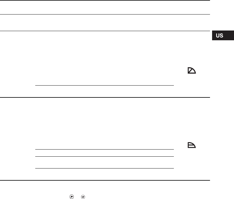
WARNING!
Prior to installation, read these
installation and operating instructions.
Installation and operation must comply
with local regulations and accepted
codes of good practice.
WARNING!
If these safety instructions are not
observed, it may result in personal
injury!
Caution If these safety instructions are not
observed, it may result in malfunction
or damage to the equipment!
Note Notes or instructions that make the job
easier and ensure safe operation.
WARNING!
The pump must not be used for the
transfer of inflammable liquids such as
diesel oil, petrol or similar liquids.
5
4. Installation
Arrows on the pump housing indicate the liquid flow
direction through the pump.
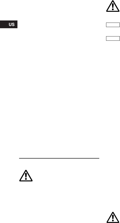
4.1 Changing the control box position
Change the control box position as follows:
1. Remove the inspection screw (1) and the four
Allen screws (6 mm) (2) in the stator housing, see
fig. 1.
2. Lift off the stator housing (3). Keep the rotor (4) in
place using a suitable tool, e.g. a T-key (M8) (5),
see fig. 2.
3. Check that the O-ring (6) is intact.
A defective O-ring must be replaced.
4. Hold the stator housing/control box (3) in the
desired position.
5. Lower the stator housing over the rotor.
Keep the rotor in place as described in point 2.
6. Fit and tighten the four screws, torque
14-17.5 Nm, and the inspection screw, torque
8-10 Nm.
Fig. 1 Removing the control box
Fig. 2 Changing the control box position
4.2 Two pumps in parallel
Two pumps in parallel can be controlled via the
optional GENI module. Both pumps should have a
GENI module installed in the control box. The
modules are connected with a wire. The modules
determine the pump operating mode, see section
7.11 GENI module.
4.3 Check valve
If a check valve is fitted in the pipe system, see fig.
3, it must be ensured that the set minimum discharge
pressure of the pump is always higher than the
closing pressure of the valve. This is especially
important in proportional-pressure control mode
(reduced head at low flows).
Fig. 3 Check valve
4.4 Frost protection
If the pump is not used during periods of frost,
necessary steps must be taken to prevent frost
bursts.
WARNING!
Before any dismantling of the pump,
the system must be drained or the
isolating valves on either side of the
pump must be closed as the pumped
liquid may be scalding hot and under
high pressure.
TM03 8910 2707
TM03 8911 2707
Pos. Description
1 Inspection screw
2Screw
3 Stator housing/control box
4 Rotor
5 T-key (not provided with the pump)
6 O-ring
TM02 0640 0301
Note
Additives with a density and/or
kinematic viscosity higher than those/
that of water will reduce the hydraulic
performance.
6
5. Electrical connection
The electrical connection and protection should be
carried out in accordance with local regulations.
• The pump requires no external motor protection.
• The operating voltage and frequency are marked
on the pump nameplate. Please make sure that
the motor is suitable for the electricity supply on
which it will be used.
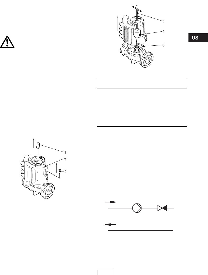
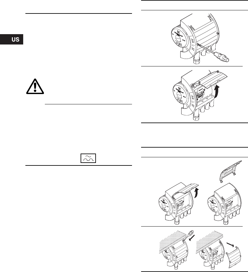
Open the control box cover as shown in fig. 4.
Fig. 4 Opening the control box
If the control box cover cannot be lifted sufficiently, it
can be removed as shown in fig. 5.
Fig. 5 Removing the control box cover
5.1 Supply voltage
1 x 230 V ± 10 %, 50/60 Hz.
WARNING!
Never make any connections in the
pump control box unless the electricity
supply has been switched off for at
least 5 minutes.
The ground terminal of the pump must
be earthed.
The pump must be connected to an
external mains switch with a contact
separation of at least 1/8 inch (3 mm) in
each pole.
Grounding or neutralization can be
used for protection against indirect
contact.
Megging must be carried out as
described in section 10. Megging.
If the pump is connected to an electric
installation where an earth leakage
circuit breaker (ELCB) is used as
additional protection, this circuit
breaker must trip out when earth fault
currents with DC content (pulsating
DC) occur.
The earth leakage circuit breaker must
be marked with the symbol shown:
Step Action
1
TM02 0456 3503
2
TM02 0457 3503
Step Action
1
TM02 7441 3503
2
TM02 7442 3503
7
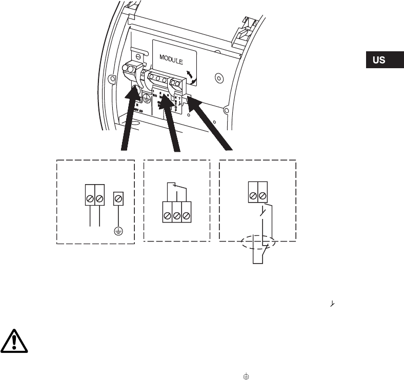
5.2 Connection diagram
Fig. 6 Wiring diagram
Concerning demands on signal wires and signal
transmitters, see section 11. Technical data.
A connection example can be found on page 49.
Note:
• If no external on/off switch is connected, the
connection across terminals STOP and should
be maintained.
• All cables used must be heat-resistant up to
+185 °F (+85 °C).
• All cables used must be installed in accordance
with NEC or applicable local codes and
regulations.
• If a GENI module is fitted, the screen must be
connected to . See page 50.
TM02 0235 1007
S
T
O
P
78
NC NO C
213
N
L
Supply connection Signal output Start/stop input
NC NO C
WARNING!
•Wires connected to
– supply terminals,
– outputs NC, NO, C and
– start/stop input
must be separated from each other
and from the supply by reinforced
insulation.
•All wires connected to a terminal
block must be tied up at the
terminals.
8
6. Start-up
Do not start the pump until the system has been
filled with liquid and vented. Furthermore, the
required minimum inlet pressure must be available at
the pump inlet, see section 11. Technical data.
The system cannot be vented through the pump.
The pump can be vented by slackening the
inspection screw.
Fig. 7 Venting the pump
WARNING!
If the inspection screw is to be
loosened, see fig. 7, care should be
taken to ensure that the escaping,
scalding hot liquid does not cause
personal injury or damage to
components.
TM03 8912 2707
Inspection screw
9
7. Functions
Most functions can be selected on the pump control panel. However, some functions can only be selected with
the R100 or via expansion modules.
On the pump control panel, see fig. 13, page 15:
•AUTOADAPT (factory setting)
Recommended for most heating installations.
During operation, the pump automatically makes the necessary adjustment to the actual system
characteristic. This setting ensures minimum energy consumption and noise level which reduces operating
costs and increases comfort.
•Proportional-pressure control
The pump head is changed continuously in accordance with the water demand in the system. The desired
setpoint can be set on the pump control panel.
•Constant-pressure control
A constant head is maintained, irrespective of water demand. The desired setpoint can be set on the pump
control panel.
•Automatic night-time duty
The pump changes automatically between normal duty and night-time duty depending on the supply-pipe
temperature. Automatic night-time duty can be combined with the above-mentioned control modes.
Further functions:
Via the digital input:
•External start/stop
The pump can be started or stopped via the digital input.
With the R100 remote control:
•Constant-curve duty
The pump runs at a constant speed, on or between the max. and min. curves.
•Temperature influence
The head varies depending on the liquid temperature.
•External fault and operating signal
The pump controls an external fault or operating signal device via a potential-free output.
Via expansion modules:
GENI module
•External analog control of head or speed via a signal from an external 0-10 V signal transmitter.
•External forced control via inputs for:
- Max. curve,
- Min. curve.
•Bus communication via GENIbus
The pump can be controlled and monitored by a GRUNDFOS Pump Management System 2000,
a building management system or another type of external control system.
•Control of two pumps in parallel
The control of two pumps in parallel is described in section 7.11.
LON module
•Bus communication via LON
This module enables connection to a network based on LonWorks® technology and to other units which
are based on this communication standard.
10
7.1 Control modes
A GRUNDFOS MAGNA pump can be set to the
control mode which is most suitable for the individual
system.
Possible control modes:
•AUTO
ADAPT (factory setting)
• Proportional pressure
• Constant pressure.
Each of the control modes can be combined with
automatic night-time duty, see section 7.3 Automatic
night-time duty.
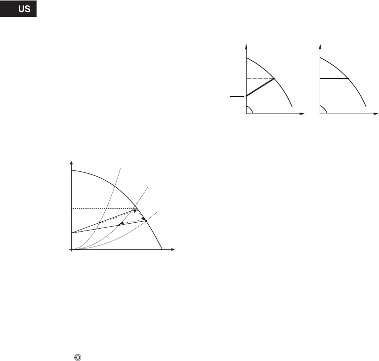
AUTOADAPT
To be set on the control panel or with the R100, see
section 8. Setting the pump.
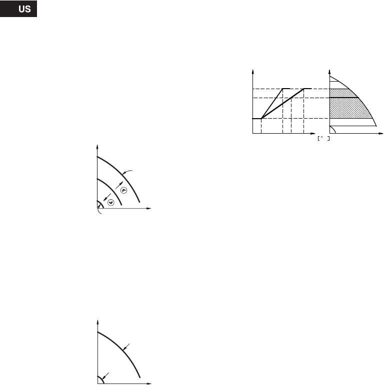
The control mode AUTOADAPT continuously adapts
the pump performance.
The setpoint (Hset1) of the pump has been factory-
set as follows and cannot be changed manually:
• MAGNA 40-120, 65-120 to 21 feet (6.5 m).
• MAGNA 65-60 to 11.5 feet (3.5 m).
When the pump registers a lower pressure on the
max. curve, A2, the AUTOADAPT function
automatically selects a correspondingly lower control
curve, Hset2, thus reducing the energy consumption.
Fig. 8 AUTOADAPT
A1: Original duty point.
A2: Lower registered pressure on the max. curve.
A3: New duty point after AUTOADAPT control.
Hset1: Original setpoint.
Hset2: New setpoint after AUTOADAPT control.
Hfac.: Factory-set setpoint.
The AUTOADAPT function can be reset by pressing
the button for approx. 10 seconds until the control
mode is back to the starting point (AUTOADAPT or
AUTOADAPT with automatic night-time duty).
Proportional-pressure control
To be set on the control panel or with the R100, see
section 8. Setting the pump.
The pump head is reduced as the water demand
declines and increased as the water demand rises,
see fig. 9.
Constant-pressure control
To be set on the control panel or with the R100, see
section 8. Setting the pump.
The pump maintains a constant pressure,
irrespective of water demand, see fig. 9.
Fig. 9 Pressure control
TM02 0251 4800
Q
H
Hmax.
Hfac.
A1
A3A2
Hset2
Hset1
TM00 5546 4596
2
H
Q
H
Q
Proportional
pressure Constant
pressure
Hset Hset
Hset
2
11
7.2 Selection of control mode
7.2.1 Setpoint setting
If AUTOADAPT is selected, the setpoint cannot be set.
The setpoint can be set by pressing or when
the pump is in control mode:
• proportional pressure
• constant pressure
• constant-curve duty.
Set the setpoint so that it matches the system.
A too high setting may result in noise in the system
whereas a too low setting may result in insufficient
heating or cooling in the system.
System type Description Select this
control mode
Typical heating
systems
Grundfos recommends to let the pump remain in AUTOADAPT mode.
This ensures optimum performance at the lowest possible energy
consumption. AUTOADAPT
Relatively great
head losses in
the distribution
pipes
1. Heating
systems with
thermostatic
valves and:
• with a dimensioned pump head higher than 13 feet
(4 m),
Proportional
pressure
• very long distribution pipes,
• strongly throttled pipe balancing valves,
• differential pressure regulators,
• great head losses in those parts of the system
through which the total quantity of water flows
(e.g. boiler, heat exchanger and distribution pipe up
to the first branching).
2. Primary circuit pumps in systems with great head losses in the primary
circuit.
Relatively small
head losses in
the distribution
pipes
1. Heating
systems with
thermostatic
valves and:
• with a pump head lower than 6.5 feet ( 2 m),
Constant
pressure
• designed for natural circulation,
• with small head losses in those parts of the system
through which the total quantity of water flows
(e.g. boiler, heat exchanger and distribution pipe up
to the first branching) or
• designed for a high differential temperature
between supply pipe and return pipe (e.g. district
heating).
2. Radiant floor heating systems with thermostatic valves.
3. One-pipe heating systems with thermostatic valves or pipe balancing
valves.
4. Primary circuit pumps in systems with small head losses in the primary
circuit.
12
7.3 Automatic night-time duty
To be set on the control panel or with the R100, see
section 8. Setting the pump.
Once automatic night-time duty has been activated,
the pump automatically changes between normal
duty and night-time duty (duty at low performance).
Changeover between normal duty and night-time
duty is dependent on the supply-pipe temperature.
The pump automatically changes over to night-time
duty when the built-in sensor registers a supply-pipe
temperature drop of more than 18-27 °F (10-15 °C)
within approx. 2 hours. The temperature drop must
be at least 0.18 °F/min. (0.1 °C/min.).
Changeover to normal duty takes place without a
time lag when the temperature has increased by
approx. 18 °F (10 °C).
7.4 Constant-curve duty
To be set with the R100, see section 8. Setting the
pump.
The pump can be set to operate according to a
constant curve, like an uncontrolled pump, see
fig. 10.
Fig. 10 Operating curves
7.5 Max. or min. curve duty
To be set on the control panel, with the R100 or via
GENI module, see section 8. Setting the pump.
The pump can be set to operate according to the
max. or min. curve, like an uncontrolled pump, see
fig. 11.
This operating mode is available, irrespective of the
control mode.
Fig. 11 Max. and min. curves
The max. curve mode can be selected if an
uncontrolled pump is required.
The min. curve mode can be used in periods in
which a minimum flow is required. This operating
mode is for instance suitable for manual night-time
duty if automatic night-time duty is not desired.
7.6 Temperature influence
The temperature influence function is available with
proportional- or constant-pressure control mode.
To be set with the R100, see section 8. Setting the
pump.
When the temperature influence function is
activated, the setpoint for head will be reduced
according to the liquid temperature.
The temperature influence limits can be set to 122 °F
(50 °C) or 176 °F (80 °C). The temperature limits are
not adjustable.
These temperature limits are called Tmax.. The
setpoint is reduced in relation to the head set
(= 100 %) according to the characteristics below.
Fig. 12 Temperature influence
In the above example, Tmax. = 176 °F (80 °C) has
been selected. The actual liquid temperature Tactual
causes the setpoint for head to be reduced from
100 % to Hactual.
The temperature influence function requires:
• Proportional- or constant-pressure control mode.
• The pump must be installed in the supply-side
pipe.
• System with supply-pipe temperature control.
Temperature influence is suitable in:
• systems with variable flows (e.g. two-pipe heating
systems), in which the activation of the
temperature influence function will ensure a
further reduction of the pump performance in
periods with small heating demands and
consequently a reduced supply-pipe temperature.
• systems with almost constant flows (e.g. one-pipe
heating systems and radiant floor heating
systems), in which variable heating demands
cannot be registered as changes in the head as is
the case with two-pipe heating systems. In such
systems, the pump performance can only be
adjusted by activating the temperature influence
function.
Selection of Tmax.
In systems with a dimensioned supply-pipe
temperature of:
• up to and including 131 °F (55 °C), select Tmax. =
122 °F (50 °C),
• above 131 °F (55 °C), select Tmax. = 176 °F
(80 °C).
TM02 0245 0904TM00 5547 4596
H
Q
Max.
Min.
Q
H
Max.
Min.
TM03 8791 2507
30%
100%
FT
17612268
HH
Q
Tactual
Hactual
13
7.7 External start/stop
The pump can be started or stopped via an external
potential-free contact or a relay connected to
terminals 7 and 8, see section 5.2 Connection
diagram.
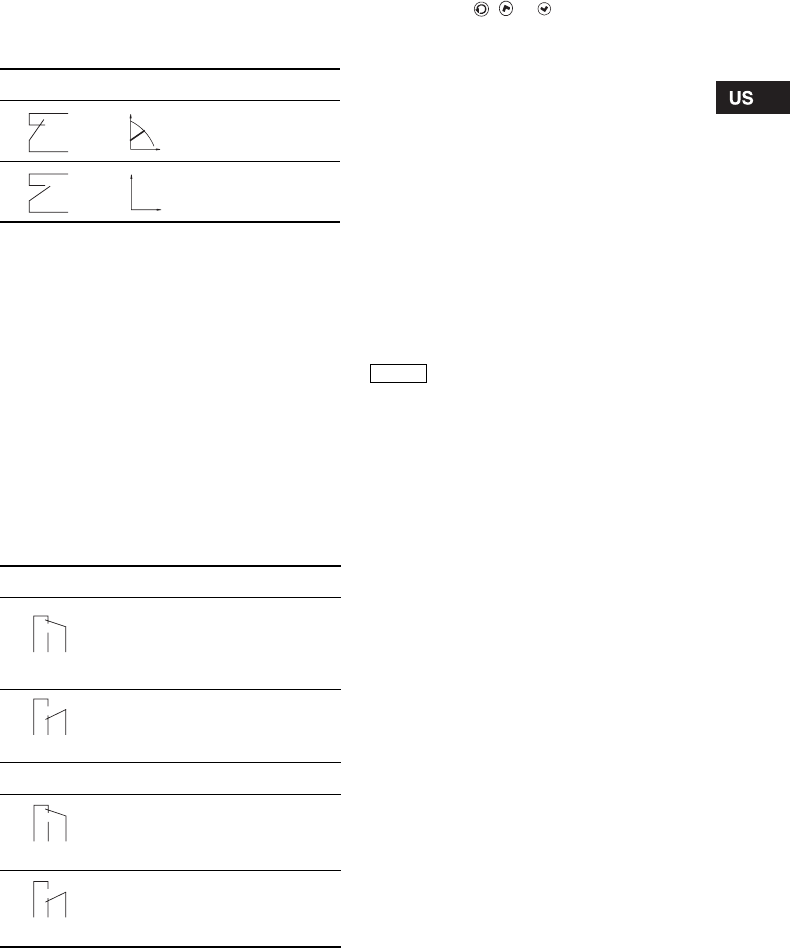
Functional diagram: Start/stop input
7.8 Signal relay
The pump incorporates a signal relay, terminals
1, 2 and 3, for a potential-free fault and operating
signal. The function of the signal relay, fault signal
(factory setting) or operating signal, is set with the
R100.
The output, terminals 1, 2 and 3, is electrically
separated from the rest of the controller.
The signal relay is activated as follows:
•Fault signal
The signal relay is activated together with the
red indicator light on the pump, see section
8.2 Control panel.
•Operating signal
The signal relay is activated together with the
green indicator light on the pump, see section
8.2 Control panel.
Functions of signal relay
Resetting of fault indications
A fault indication can be reset in one of the following
ways:
• Briefly press , or on the pump. This will
not influence the pump performance set.
• Briefly switch off the electricity supply to the
pump.
• With the R100, see section 8.4 R100 display
overview.
Before the pump can revert to normal duty, the fault
cause must be eliminated.
If the fault disappears by itself, the fault indication
will automatically be reset.
The fault cause will be stored in the pump alarm log.
The latest five faults can be called up with the R100.
7.9 Indicator lights
For position on pump, see fig. 13, section 8.2 Control
panel.
The indicator lights, pos. 2, are used for operating
and fault indication. Furthermore, they indicate
whether the pump is externally controlled.
The function of the operating and fault indicator
lights can be found in section 9. Fault finding chart.
The indicator light for external control is on
• if the pump control panel is inactive,
• if the pump is in constant-curve operating mode,
• if the temperature influence is active or
• if the pump is controlled by an external unit.
Start/stop input
Normal duty
Stop
Signal relay Fault signal
Not activated:
• The electricity supply has been
switched off.
• The pump has not registered
afault.
Activated:
• The pump has registered a fault.
Signal relay Operating signal
Not activated:
• The pump has been set to stop.
• The pump has registered a fault
and is unable to run.
Activated:
• The pump is running.
• The pump has registered a fault,
but is able to run.
Q
H
Q
H
132
NC NO C
12 3
NC NO C
132
NC NO C
12 3
NC NO C
Note When the R100 remote control
communicates with the pump, the red
indicator light will flash rapidly.

14
7.10 Expansion modules
The pump can be fitted with an expansion module
enabling communication with external signals
(signal transmitters).
Two types of expansion module are available:
• GENI module.
For mounting and operation, see separate
installation and operating instructions for the
GENI module.
• LON module.
For mounting, see separate fitting instructions for
the LON module.
7.11 GENI module
The GENI module offers the following functions:
• External analog 0-10 V control
• External forced control
• Bus communication via GENIbus
• Control of two pumps in parallel.
See separate installation and operating instructions
for the GENI module.
7.12 LON module
The LON module offers the possibility of connecting
the pump to a LonWorks network. The module is
used for data transmission between a network and
pumps of the type MAGNA 40-120, 65-120 and
65-60.
For further information, see the documentation files
on the CD-ROM supplied with the LON module.
8. Setting the pump
For the setting of the pump, use:
• control panel
• R100 remote control
• bus communication (not described in detail in
these instructions, contact Grundfos).
The table shows the application of the individual
operating units and in which section the function has
been described.
"–" = not available with this operating unit.
8.1 Factory setting
The pump is factory-set to AUTOADAPT without
automatic night-time duty.
Possible settings
Control
panel
R100
AUTOADAPT 8.2.1 8.7.1
Automatic night-time duty 8.2.1 8.7.2
Proportional-pressure
control 8.2.1 8.7.1
Constant-pressure control 8.2.1 8.7.1
Setpoint setting 8.2.2 8.5.1
Max. curve duty 8.2.3 8.5.2
Min. curve duty 8.2.4 8.5.2
Constant-curve duty – 8.5.2
Temperature influence – 8.7.3
Activation/deactivation of
pump buttons –8.7.4
Allocation of pump number – 8.7.6
Start/stop 8.2.5 8.5.2
Resetting of fault
indications 8.2.6 8.5.3
Reading of various data –8.6.1 -
8.6.7
15
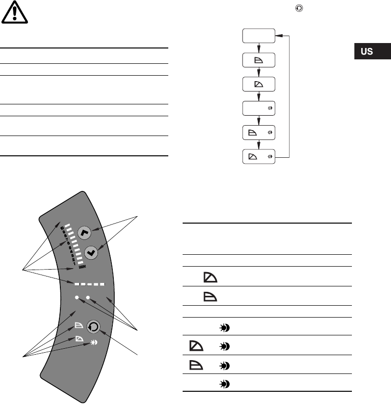
8.2 Control panel
The control panel, fig. 13, incorporates:
For further information, see section 9. Fault finding
chart.
Fig. 13 Control panel
8.2.1 Control mode setting
Description of function, see section 7.1 Control
modes.
To change the control mode, press , pos. 3,
according to this cycle:
Fig. 14 Cycle of control modes
Automatic night-time duty can be activated together
with each of the control modes.
The light symbols in pos. 4, see fig. 13, indicate the
pump settings:
"–" = no light.
WARNING!
At high liquid temperatures, the pump
may be scalding hot, only the buttons
should be touched to avoid burns.
Pos. Description
1 Buttons for setting
2
• Indicator lights for operating and fault
indication and
• symbol for indication of external control
3 Button for change of control mode
4Light symbols for indication of control
mode and night-time duty
5Light fields for indication of head, flow and
operating mode
TM03 8798 2507
EXT
Q100%
MAX
STO P
5
4
1
2
3
AUTO
ADAPT
H
TM03 1288 1505
Light in Control mode Automatic
night-time
duty
AUTOADAPT AUTOADAPT NO
Proportional
pressure NO
Constant pressure NO
–Constant curve NO
AUTO
ADAPT AUTOADAPT YES
Proportional
pressure YES
Constant pressure YES
–Constant curve YES
AUTO
ADAPT
AUTO
ADAPT
+
+
+
16
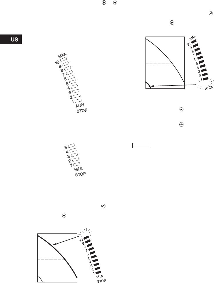
8.2.2 Setpoint setting
Set the setpoint of the pump by pressing or
when the pump has been set to proportional-
pressure control, constant-pressure control or
constant-curve duty.
The light fields, pos. 5, on the control panel indicate
the setpoint set.
MAGNA 40-120, 65-120
The light fields can indicate a maximum setpoint of
10 corresponding to 32 feet (10 m).
Fig. 15 Light fields MAGNA xx-120
MAGNA 65-60
The light fields can indicate a maximum setpoint of
5 corresponding to 16 feet (5 m).
Fig. 16 Light fields MAGNA 65-60
8.2.3 Setting to max. curve duty
Description of function, see section 7.5 Max. or min.
curve duty.
To change over to the max. curve, press
continuously until "MAX" illuminates, see fig. 17. To
change back, press continuously until the desired
setpoint is indicated.
Fig. 17 Max. curve
8.2.4 Setting to min. curve duty
Description of function, see section 7.5 Max. or min.
curve duty.
To change over to the min. curve, press
continuously until "MIN" illuminates, see fig. 18. To
change back, press continuously until the desired
setpoint is indicated.
Fig. 18 Min. curve
8.2.5 Start/stop of pump
To stop the pump, press continuously until
"STOP" illuminates. When the pump is stopped, the
green indicator light will be flashing.
To start the pump, press continuously.
8.2.6 Resetting of fault indications
The fault indications are reset by briefly pressing
any button. The settings remain unchanged. If the
fault has not disappeared, the fault indication will
reappear. The time until the fault reappears may vary
from 0 to 255 seconds.
8.3 R100 remote control
The pump is designed to communicate with the
Grundfos R100 remote control via infra-red light.
During communication, the R100 must be pointed at
the pump control panel. When the R100 is
communicating with the pump, the red indicator light
will flash rapidly.
The R100 offers additional possibilities of setting and
status displays for the pump.
TM02 0482 2507TM02 0483 2507TM02 0246 2507
H
H
MAX
H
TM02 0247 2507
Note
If the pump is to be stopped, it is
recommended to use the start/stop
input, the R100 or to switch off the
electricity supply. In this way, the
setpoint will remain unchanged when
the pump is started again.
H MIN
17
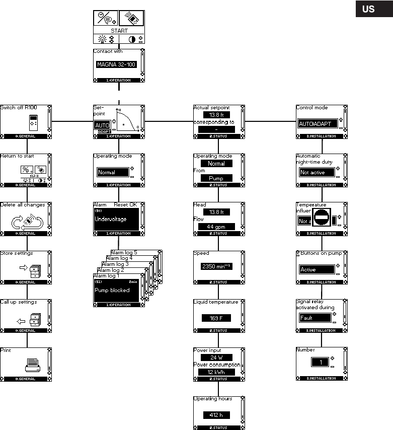
8.4 R100 display overview
The R100 displays are divided into four parallel
menus, see fig. 19:
0. GENERAL, see operating instructions for R100
1. OPERATION
2. STATUS
3. INSTALLATION
The number stated at each individual display in
fig. 19 refers to the section in which the display is
described.
Fig. 19 Menu overview
8.7.5
8.7.4
8.7.1
8.7.2
8.7.6
8.6.5
8.6.4
8.6.1
8.6.2
8.6.6
8.6.3
8.5.4
8.5.1
8.5.2
8.5.3
8.6.7
8.7.3
3. INSTALLATION2. STATUS0. GENERAL 1. OPERATION
This display appears only once, i.e. when the R100
gets contact with the pump.
18
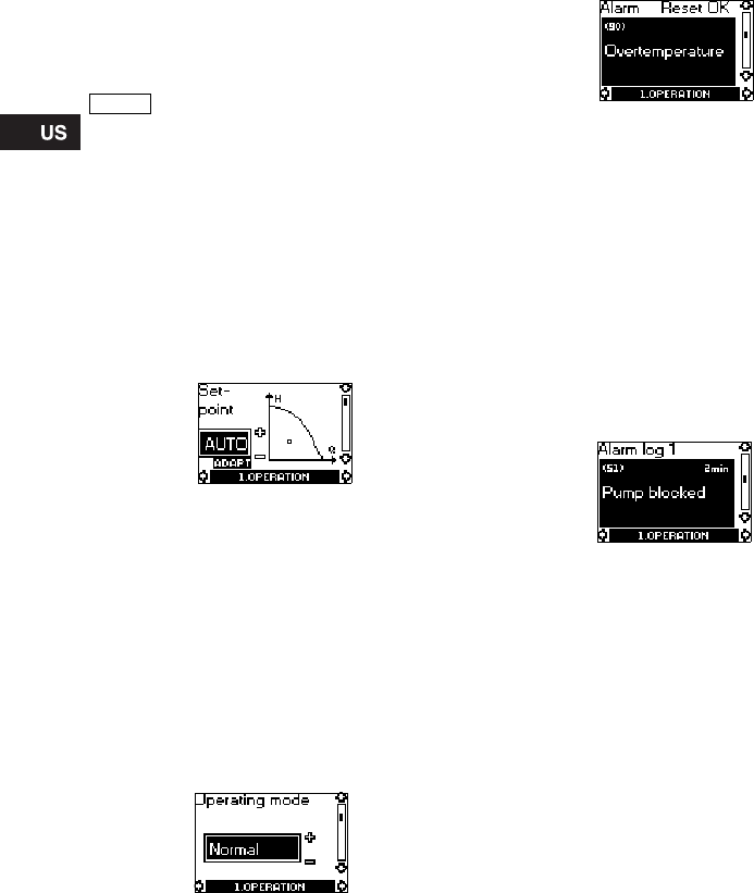
8.5 Menu OPERATION
When the communication between the R100 and the
pump has been established, "Contact with" appears
in the display. When the "arrow down" on the R100 is
pressed, menu OPERATION appears.
8.5.1 Setpoint
This display depends on the control mode selected
in the display "Control mode" in menu
INSTALLATION.
If the pump is forced-controlled via external signals,
the number of possible settings will be reduced, see
section 8.8 Priority of settings. Attempts to change
the settings will result in an indication in the display
saying that the pump is forced-controlled and
changes therefore cannot be made.
This display will appear when the pump is in
AUTOADAPT mode.
Set the desired setpoint by pressing the buttons
"+" and "–" on the R100 (not possible when the pump
is in AUTOADAPT mode).
Furthermore, it is possible to select one of the these
operating modes:
•Stop
•Min. (min. curve)
•Max. (max. curve).
If proportional pressure, constant pressure or
constant curve has been selected, the display is
different.
The actual duty point of the pump is indicated by a
square in the Q/H field. No indication at low flow.
8.5.2 Operating mode
Select an operating mode:
•Stop
•Min. (min. curve)
•Normal (AUTOADAPT, proportional pressure,
constant pressure or constant curve)
•Max. (max. curve).
8.5.3 Fault indications
If the pump is faulty, the cause will appear in this
display.
Possible causes:
•Pump blocked
•Internal fault
•Overvoltage
•Undervoltage
•Overtemperature
•Module fault
•Fault in module communication.
The fault indication can be reset in this display.
If the fault has not disappeared when resetting is
attempted, the fault indication will reappear in the
display when communicating with the pump.
8.5.4 Alarm log
The alarm code with text appears in this display.
The display also shows the number of minutes the
pump has been connected to the electricity supply
after the fault occurred.
The last five fault indications will appear in the alarm
log.
Note The display "Contact with" appears
only once, i.e. when the R100 gets
contact with the pump.
19
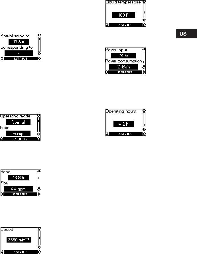
8.6 Menu STATUS
The displays appearing in this menu are status
displays only. It is not possible to change or set
values.
The actual values in the display are indicative and
based on estimation.
8.6.1 Actual setpoint
Field "Actual setpoint":
Actual setpoint of pump.
Field "corresponding to":
Actual setpoint in % of the setpoint set if the pump is
connected to an external analog 0-10 V signal
transmitter or if temperature influence or
proportional-pressure control is activated.
8.6.2 Operating mode
This display shows the actual operating mode (Stop,
Min., Normal or Max.) and where it was selected
(Pump, R100, BUS or External).
8.6.3 Head and flow
The actual head and flow of the pump.
If "<" is indicated in front of the flow, the flow is less
than the displayed value.
8.6.4 Speed
The actual pump speed.
8.6.5 Liquid temperature
The actual temperature of the pumped liquid.
8.6.6 Power input and power consumption
Actual power input and power consumption of the
pump.
The value of power consumption is an accumulated
value and cannot be set to zero.
8.6.7 Operating hours
Operating hours of the pump.
The value of operating hours is an accumulated
value and cannot be set to zero.
20
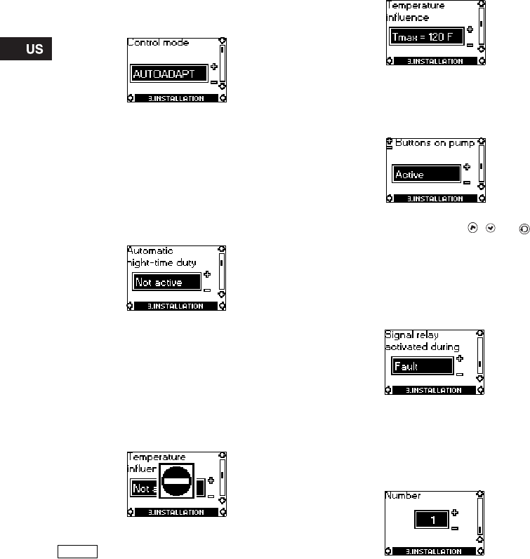
8.7 Menu INSTALLATION
This menu shows the settings that should be
considered when installing the pump.
8.7.1 Control mode
Description of function, see section 7.1 Control
modes or section 7.4 Constant-curve duty.
Select one of the control modes:
•AUTO
ADAPT
•Prop. pressure (proportional pressure)
•Const. pressure (constant pressure)
•Const. curve (constant curve).
Setting of setpoint and curve is carried out in display
8.5.1 Setpoint in menu OPERATION (not possible
when the pump is in AUTOADAPT mode).
8.7.2 Automatic night-time duty
In this display, automatic night-time duty can be
activated or deactivated.
Automatic night-time duty can be set to:
•Active
•Not active,
irrespective of the control mode selected.
8.7.3 Temperature influence
Description of function, see section 7.6 Temperature
influence.
The temperature influence function can be activated
in this display when the control mode is proportional
pressure or constant pressure, see section
8.7.1 Control mode.
In the case of temperature influence, the pump must
be installed in the supply pipe. It is possible to
choose between maximum temperatures of 122 °F
(50 °C) and 176 °F (80 °C).
When the temperature influence is active, a small
thermometer is shown in the display "Setpoint" in
menu OPERATION, see section 8.5.1 Setpoint.
8.7.4 Buttons on pump
To prevent unauthorized persons from operating the
pump, the function of the buttons , and can
be deactivated in this display. The buttons can be
reactivated only with the R100.
The buttons can be set to:
•Active
•Not active.
8.7.5 Signal relay
In this display, the function of the internal signal
relay can be set:
•Fault (functions as a fault signal relay)
•Operation (functions as an operating signal
relay).
8.7.6 Pump number
A number from 1 up to and including 64 can be
allocated to a pump or can be changed so that the
R100, Pump Management System 2000 or other
systems can distinguish between two or more
pumps.
Note
If the pump is in control mode
AUTOADAPT or constant curve, the
temperature influence cannot be set
with the R100.
21
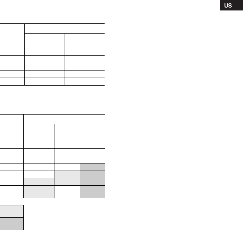
8.8 Priority of settings
The external forced-control signals will influence the
settings available on the pump control panel and with
the R100. However, the pump can always be set to
max. curve duty or to stop on the pump control panel
or with the R100.
If two or more functions are activated at the same
time, the pump will operate according to the setting
with the highest priority.
The priority of the settings is as shown in the table.
Without expansion module
Example: If the pump has been forced to stop via an
external signal, the pump control panel or the R100
can only set the pump to max. curve.
With expansion module
As illustrated in the table, the pump does not react to
external signals (max. curve and min. curve) when
the pump is controlled via bus.
If the pump is to react to external signals (max. curve
and min. curve), the system must be configured for
that function.
For further details, please contact Grundfos.
Priority
Possible settings
Pump control
panel or R100 External signals
1 Stop
2Max. curve
3Stop
4Min. curve
5 Setpoint setting
Priority
Possible settings
Pump
control
panel
or R100
External
signals Bus
signal
1 Stop
2 Max. curve
3Stop
Stop
4Max.curve Max.curve
5Min. curve Min. curve Min. curve
6Setpoint
setting Setpoint
setting
Not active when the pump is controlled
via bus.
Only active when the pump is
controlled via bus.
22
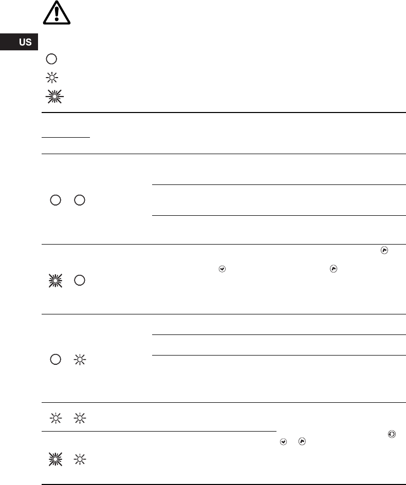
9. Fault finding chart
WARNING!
Before removing the control box cover, make sure that the electricity supply has been
switched off for at least 5 minutes.
The pumped liquid may be scalding hot and under high pressure. Before any removal or
dismantling of the pump, the system must therefore be drained or the isolating valves on
either side of the pump must be closed.
Indicator light is off.
Indicator light is on.
Indicator light is flashing.
Indicator
lights Fault Cause Remedy
Green Red
The pump is not
running. One fuse in the installation is
blown/tripped off. Replace/reset the fuse.
Check that the electricity supply falls
within the specified range.
The current-operated or voltage-
operated circuit breaker has tripped
off.
Reset the circuit breaker.
Check that the electricity supply falls
within the specified range.
The pump may be defective. Replace the pump or call
GRUNDFOS SERVICE for
assistance.
The pump is not
running. The pump has been stopped in one
of the following ways:
1. With the button .
2. With the R100.
3. External on/off switch in position
off.
4. Via bus signal.
1. Start the pump by pressing .
2. Start the pump with the R100 or
by pressing .
3. Switch on the on/off switch.
4. Start the pump via bus signal.
The pump has
stopped due to a
fault.
Electricity supply failure. Check that the electricity supply falls
within the specified range.
Pump blocked and/or impurities in
the pump. Dismantle and clean the pump.
The pump may be defective. Use the R100 for fault finding, see
section 8.5.3 Fault indications.
Replace the pump or call
GRUNDFOS SERVICE for
assistance.
The pump is
running but is
faulty.
The pump is faulty, but is able to
operate. The pump is able to operate.
Try to reset the fault indication by
briefly switching off the electricity
supply or by pressing the button ,
or .
Use the R100 for fault finding, see
section 8.5.3 Fault indications.
In the case of repeated faults,
contact GRUNDFOS SERVICE.
The pump has
been set to stop
and is faulty.
The pump is faulty, but is able to
operate (has been set to STOP).
23
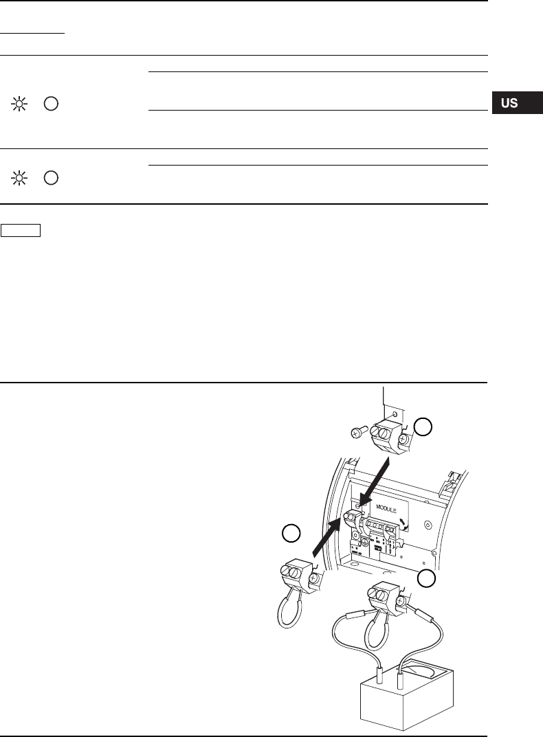
10. Megging
Megging of an installation incorporating a
GRUNDFOS MAGNA pump is not allowed, as the
built-in electronics may be damaged. If megging of
the pump is necessary, the pump should be
electrically separated from the installation.
Megging of the pump can be carried out as
described below.
Noise in the
system. Air in the system. Vent the system.
The flow is too high. Reduce the setpoint and possibly
change over to AUTOADAPT or
constant pressure.
The pressure is too high. Reduce the setpoint and possibly
change over to AUTOADAPT or
proportional pressure.
Noise in the
pump. Air in the pump. Vent the pump.
The inlet pressure is too low. Increase the inlet pressure and/or
check air volume in the expansion
tank (if installed).
Indicator
lights Fault Cause Remedy
Green Red
Note The R100 can also be used for fault
finding.
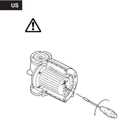
Megging of pumps
1. Switch off the electricity supply.
2. Remove the wires from terminals L and N and the earth
conductor.
3. Short-circuit terminals L and N using a short wire
(see B).
4. Remove the screw for electronics frame connection
(see A).
5. Test between terminals L/N and earth (see C).
Maximum test voltage: 1000 VAC/1500 VDC.
Note: Never test between supply terminals (L and N).
Maximum permissible leakage current: < 35 mA.
6. Fit the screw for electronics frame connection (see A).
7. Remove the short wire between terminals L and N
(see B).
8. Fit the supply wires to terminals L and N and the earth
conductor.
9. Switch on the electricity supply.
TM02 0238 0904
A
B
C

24
11. Technical data
Supply voltage
1 x 230 ± 10 %, 50/60 Hz.
Motor protection
The pump requires no external motor protection.
Enclosure class
IP 44.
Insulation class
F.
Relative air humidity
Maximum 95 %.
Ambient temperature
32 °F to 104 °F (0 °C to +40 °C).
Temperature class
TF110 to EN 60335-2-51.
Liquid temperature
Maximum +230 °F (+110 °C).
Continuously: +59 °F to +203 °F (+15 °C to +95 °C).
Pumps in domestic hot-water systems:
Continuously: +59 °F to +140 °F (+15 °C to +60 °C).
Maximum system pressure
175 psi (12 bar/1.2 MPa).
Number of bolt holes in the pump flange:
• 2 holes (MAGNA 40-120) and
• 4 holes (MAGNA 65-120, 65-60).
Inlet pressure
Recommended inlet pressures:
• Min. 13.1 psi at 167 °F (0.9 bar at +75 °C).
• Min. 17.5 psi at 203 °F (1.2 bar at +95 °C).
EMC (electromagnetic compatibility)
EN 61800-3.
Sound pressure level
The sound pressure level of the pump is lower than
54 dB(A).
Leakage current
The pump mains filter will cause a discharge current
to earth during operation. Ileakage < 3.5 mA.
Standby loss
Lower than 3 W.
Pump inputs and outputs
Inputs of pump with GENI module
Input of pump with LON module
12. Disposal
90 percent of this product is recyclable. Please
utilize public or private waste collection services for
recycling.
Ambient
temperature Liquid temperature
[°F] [°C] Min.
[°F] Max.
[°F] Min.
[°C] Max.
[°C]
32 0 59 203/230 15 95/110
86 30 59 203/230 15 95/110
95 35 59 194/194 15 90/90
104 40 59 158/158 15 70/70
Signal output
Internal potential-free change-
over contact.
Maximum load:
250 V, 2 A, AC1.
Minimum load: 5 V, 100 mA.
Screened cable, depending on
signal level.
Input for external
start/stop
External potential-free switch.
Contact load: 5 V, 10 mA.
Screened cable.
Loop resistance:
Maximum 130 Ω.
Inputs for max.
and min. curves
External potential-free switch.
Contact load: 5 V, 1 mA.
Screened cable.
Loop resistance:
Maximum 130 Ω.
Input for analog
0-10 V signal
External signal: 0-10 VDC.
Maximum load: 1 mA.
Screened cable.
Bus input
Grundfos bus protocol,
GENIbus protocol, RS-485.
Screened cable.
Wire cross section:
0.25 - 1 mm2.
Cable length:
Maximum 3900 feet (1200 m).
Bus input
LonTalk® protocol, FTT 10.
Twisted-pair cable.
Wire cross section:
0.25 - 1 mm2.
Subject to alterations.
47
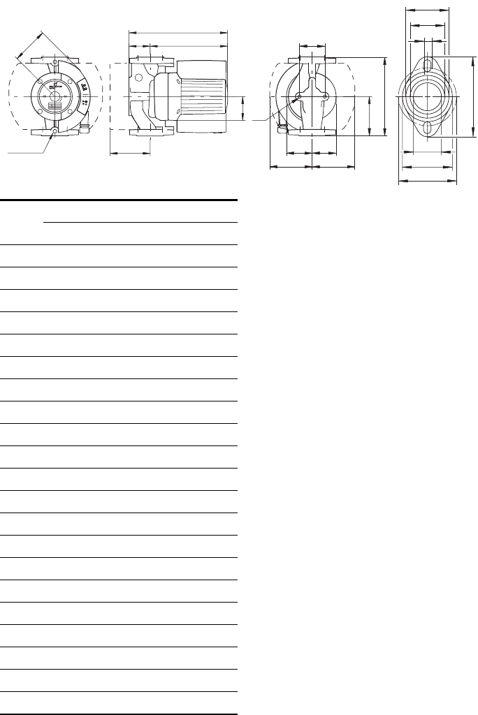
* 3 1/8" (80 mm), stainless-steel pump housing /
corps du circulateur en acier inoxydable
TM03 9055 3207
D6
D2
D3
D7
D1
D4
D5
Rp 1/4
B2
H2H1
H3
B1
H4
L1
B5
B6 B7
M
B4 B3
L3
1/4" NP
T
MAGNA 40-120
GF 15/40
[Inch/pouce] [mm]
L1 8 1/2 216
L3 4 1/4 108
B1 3 1/16 77
B2 4 1/2 115
B3 2 15/16 75
B4 3 1/8 80
B5 3 3/4 or 3 1/8* 96 or 80*
B6 5 1/2 140
B7 4 5/16 110
H1 2 11/16 68
H2 9 1/2 242
H3 12 3/16 310
H4 3 3/4 96
D1 1 9/16 40
D2 2 15/16 75
D3 3 1/8 or 3 7/16 80/87
D4 4 3/4 120
D5 1/2 12
D6 1 15/16 49
D7 2 3/8 60
48
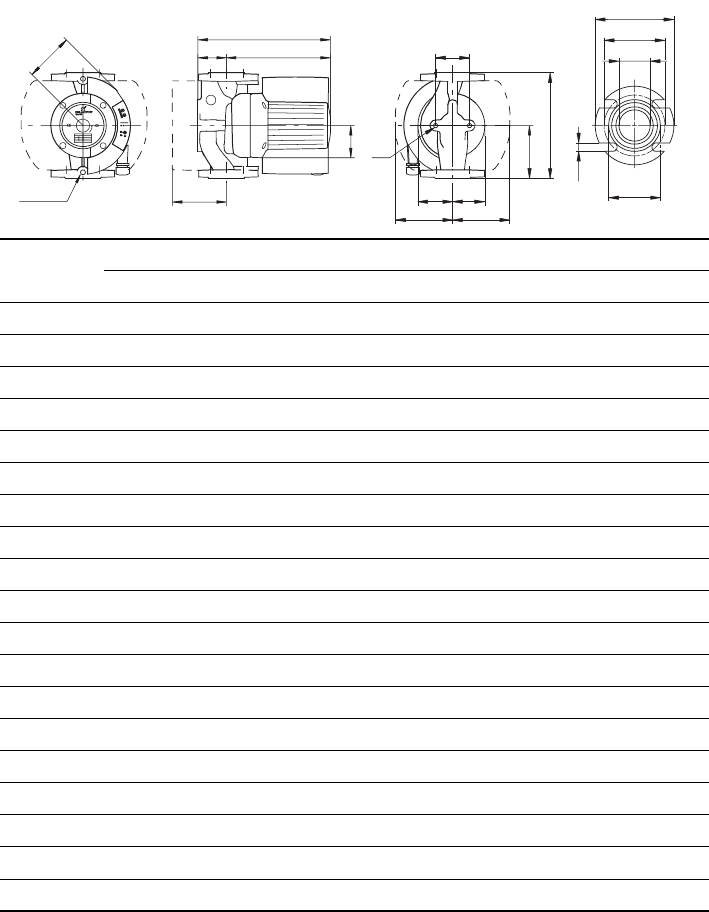
* 3 1/8" (80 mm), stainless-steel pump housing / corps du circulateur en acier inoxydable
TM03 9058 3307
MAGNA 65-120 MAGNA 65-60
GF 53 GF 53
[Inch/pouce] [mm] [Inch/pouce] [mm]
L1 11 1/2 292 11 1/2 292
L3 5 3/4 146 5 3/4 146
B1 3 1/16 77 3 1/16 77
B2 4 15/16 125 4 15/16 125
B3 3 7/16 88 3 7/16 88
B4 4 1/8 104 4 1/8 104
B5 3 3/4 or 3 1/8* 96 or 80* 3 3/4 or 3 1/8* 96 or 80*
B6 5 1/2 140 5 1/2 140
B7 4 5/16 110 4 5/16 110
H1 3 1/4 82 3 1/4 82
H2 9 15/16 252 9 15/16 252
H3 13 1/8 334 13 1/8 334
H4 4 3/16 107 4 3/16 107
D1 2 1/2 63 2 1/2 63
D2 3 15/16 100 3 15/16 100
D3 5 127 5 127
D4 6 152 6 152
D5 5/8 16 5/8 16
D5
D4
D3
D1
D2
NPT 1/4
B2
H2H1
H3
B1
H4
L1
B5
B6 B7
M
B4 B3
L3
1/4" NP
T
49
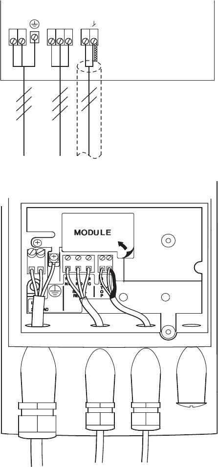
Connection diagram without optional expansion modules
Diagramme montrant la connexion sans l'utilisation d'un module d'extension
optionnel
MAGNA 40-120, 65-120, 65-60
TM02 0477 1004
C
NONC
NL
O
P
T
S
78321
50
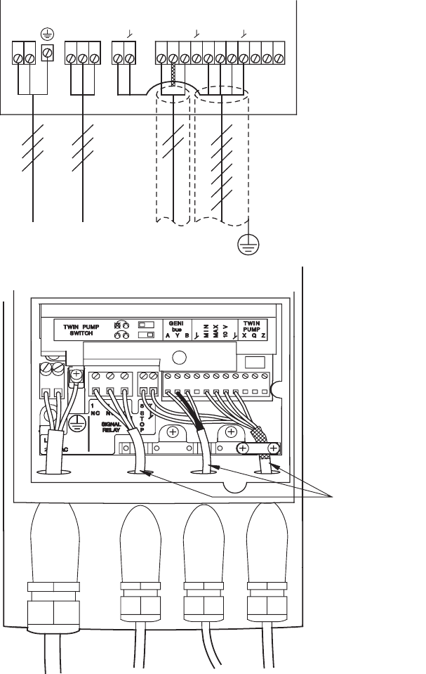
Connection diagram with optional GENI module with no external stop function
Diagramme montrant la connexion en utilisant le module GENI optionnel sans
fonction d'arrêt externe
MAGNA 40-120, 65-120, 65-60 with GENI module (avec module GENI)
TM02 0478 1004
Max. ø7
CNONCNL
O
P
T
S
AY B XQZ
MIN
MAX
10 V
2322211211109765478321
Max. OD:
0.275 inches/
pouces (7 mm)
51
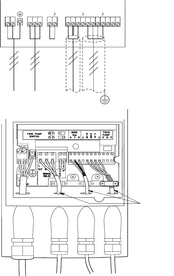
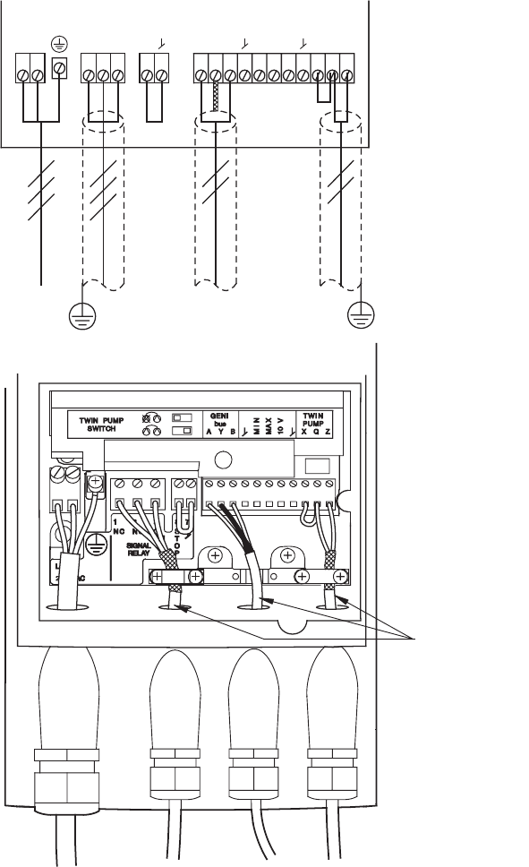
Connection diagram with optional GENI module with external stop function
Diagramme montrant la connexion en utilisant le module GENI optionnel avec
fonction d'arrêt externe
MAGNA 40-120, 65-120, 65-60 with GENI module (avec module GENI)
TM02 0479 1004
CNONCNL
O
P
T
S
AY B XQZ
MIN
MAX
10 V
2322211211109765478321
Max. ø7
Max. OD:
0.275 inches/
pouces (7 mm)
52
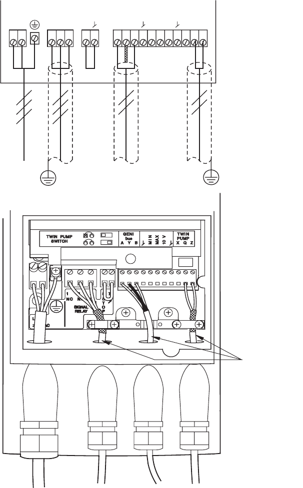
Wiring diagram for two pumps in parallel (master)
Diagramme de connexion pour deux circulateurs en parallèle (maître)
MAGNA 40-120, 65-120, 65-60 with GENI module (avec module GENI)
TM02 0480 1004
Max. ø7
CNONCNL
O
P
T
S
AY B XQZ
MIN
MAX
10 V
2322211211109765478321
Max. OD:
0.275 inches/
pouces (7 mm)
53
Wiring diagram for two pumps in parallel (slave)
Diagramme de connexion pour deux circulateurs en parallèle (esclave)
MAGNA 40-120 65-120, 65-60 with GENI module (avec module GENI)
TM02 0481 1004
Max. ø7
CNONCNL
O
P
T
S
AY B XQZ
MIN
MAX
10 V
2322211211109765478321
Max. OD:
0.275 inches/
pouces (7 mm)
54
U.S.A.
GRUNDFOS Pumps Corporation
17100 West 118th Terrace
Olathe, Kansas 66061
Phone: +1-913-227-3400
Telefax: +1-913-227-3500
Canada
GRUNDFOS Canada Inc.
2941 Brighton Road
Oakville, Ontario
L6H 6C9
Phone: +1-905 829 9533
Telefax: +1-905 829 9512
México
Bombas GRUNDFOS de México
S.A. de C.V.
Boulevard TLC No. 15
Parque Industrial Stiva
Aeropuerto
Apodaca, N.L.C.P. 66600
Phone: +52-81-8144 4000
Telefax: +52-81-8144 4010
Addresses revised 22.09.2005

www.grundfos.com
Being responsible is our foundation
Thinking ahead makes it possible
Innovation is the essence
96746689 0907 243
L-MAG-TL-01
