18049 1 Little Giant Check Valve Submittal User Manual
18350 1 Little Giant Check Valve Submittal 18350_1_Little Giant Check Valve Submittal
20076 1 Littel Giant 940021 Submittal 20076_1_Littel Giant 940021 Submittal
20056 1 Little Giant Check Valve Brochure 20056_1_Little Giant Check Valve Brochure
User Manual: Pump 18049 1 Little Giant Check Valve Submittal
Open the PDF directly: View PDF ![]() .
.
Page Count: 2
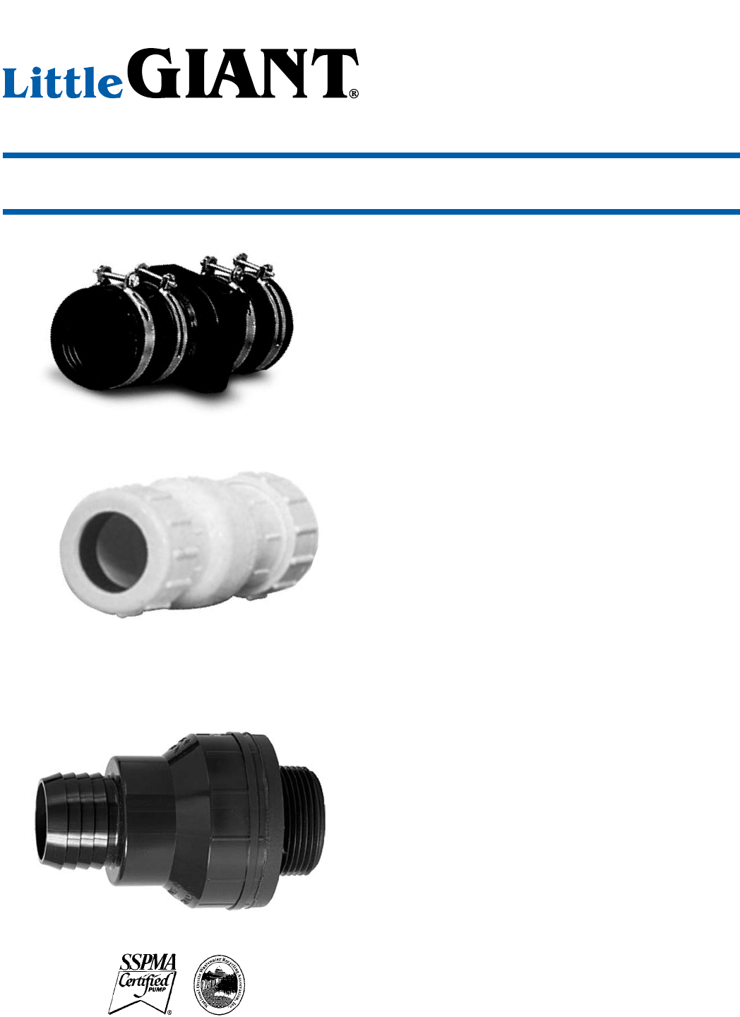
CV - 114/112 and CV-SE
Features
n ABS construction
n Easy slip fit design makes simple installation
n Durable flapper designs checks back flow of
water and sewer gasses
n Can be installed in vertical or horizontal line
n Flexible unions slip over ABS, PVC or copper pipe
n CV-114/112 fits both 1-1/4" and 1-1/2" IPS pipe
n CV-SE fits 2" IPS pipe
Accessories - Check Valves
Check Valves
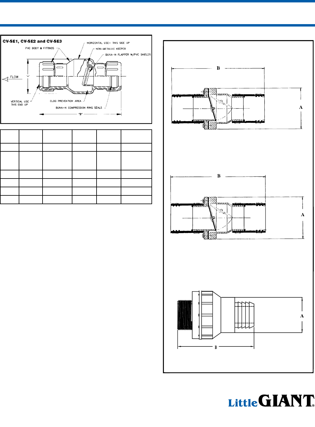
CV-SE1, CV-SE2 and CV-SE3
CV-114
CV-SE1, CV-SE2 and CV-SE3
Features
n Full flow non-clog design
n Compression end fittings allow quick and easy
installation, no threading of pipe required
n Suitable for below pit cover installation
n Can be used as a union connection
CV-114
Features
n Full port valve design
n Durable PVC construction, 1-1/4" MNPT x
1-1/4" barbed or 1-1/2" slip
n Flapper opens 100%
CV - 114/112, CV-SE
Form 994355 — 08/2007www.LittleGiantPump.com
Check Valves
ITEM
NO.
MODEL
NO.
IPS
SIZE
DIM
“A”
DIM
“B”
SOLID
HANDLING
599059 CV-114/112 1-1/4" & 1-1/2" 3" SQUARE 7.25 1"
577105 CV-114
1-1/4" MNPT
1-1/4" BARBED
& 1-1/2" SLIP
2.59 3.75 N/A
940021 CV-SE 2" 3" SQUARE 8" 3/4"
940019 CV-SE1 1-1/2" 3-1/4" 7-1/2" 1-1/2"
940022 CV-SE1 2" 4-1/4" 9-3/4" 2"
940023 CV-SE3 3" 5-3/4" 14" 3"
Guidelines for Use of Check Valve in Sewage,
Effluent and Ejector Pump Systems:
1. Valve may be installed horizontally or vertically. However,
when installed in systems handling solids, valve must be
installed horizontally or at a maximum of a 45° angle. This
will guard against any solids lodging on top of valve flapper
and preventing valve from opening on start-up.
2. Valves have flow direction arrows and horizontal and vertical
position markings molded on them. Use horizontal position
markings for all installations from horizontal to vertical to
ensure correct flapper pivot position. (Recommended maxi-
mum 45° angle on solids handling applications).
3. For submersible pump applications, drill a 3/16" hole in
discharge pipe approximately 1"–2" above the pump discharge
connection to prevent air locking of pump.
4. When check valve is used as a union, connection must be
beyond end of basin cover to make servicing of installation
easier. To use as a union connection, the following axial
movement of discharge pipe must be allowed to remove
discharge pipe from valves:
CV-SE1 — 2-3/4"
CV-SE2 — 3-1/4"
CV-SE3 — 4-1/4"
5. A gate valve should be installed after check valve to allow
servicing and removal of check valve or pipe.
6. All discharge piping should be properly supported to prevent
separation of pipe at valve.
PO Box 12010 • Oklahoma City, OK 73157
Phone: 800.701.7894 • Fax: 800.701.8046
E-mail: customerservice@littlegiant.com
CV-114
CV-SE
CV-114-112
/
