1990 2 Zoeller Guide Rail System Instructions User Manual
User Manual: Pump 1990 2 Zoeller Guide Rail System Instructions
Open the PDF directly: View PDF ![]() .
.
Page Count: 4

SECTION: Z5.00.180
ZM1170
1011
Supersedes
0508
GUIDE RAIL SYSTEMS
INSTALLATION PROCEDURES
Zoeller Engineered Products
2.5" thru 6" Pumps with Flanged Discharge
2.5 / 3" Systems – P/N 39-0094 and 39-0095
4" Systems – P/N 6039-0016 and 6039-0017
6" Systems – P/N 6039-0072 and 6039-0073
© Copyright 2011 Zoeller Co. All rights reserved.
GENERAL INFORMATION
These models are complete systems used in sewage or dewatering installations with side outlet anged pumps. They can
be used in basins at any depth. The guide rail systems are particularly useful when the liquid level is above the discharge
pump. The systems feature easy automatic engagement and disengagement for removing the pump for service or repair
without draining the basin.
General Construction: A anged discharge elbow is supplied with the rail system which also supports the lower rail
guides. The discharge elbow, as well as the mounting plate are made of durable class 30 cast iron that is epoxy coated.
Upper guide rail brackets (supplied) and intermediate guide brackets (optional) along with guide brackets are stainless
steel. The mounting plate and guide brackets (where required) are available in non-sparking brass. All models require
the use of 2" schedule 40 (galvanized steel or stainless steel) pipe for guide rails. Pipe is furnished by the user.
Lifting Cable: The pump is equipped with lifting lugs that are an integral part of the motor housing or cover for lifting.
A permanently attached chain, cable or choker (purchased separately), should be used to aid in pump installation and
removal. It is not necessary to use a separate pull chain on the mounting plate which is bolted to the pump discharge ange.
Rail Support Bracket: As mentioned above, all the rail systems utilize 2" standard pipe for the guide rails. The supplied
top rail support is to be mounted to the hatch frame. Intermediate brackets are available for deep installations. It is
recommended that a intermediate stabilizer support bracket be ordered separately and used for each 15 feet of basin
depth (20 feet for the 2.5"/3" systems).
INSTALLING RAIL SYSTEM PARTS
Discharge Base and Rails:
1. Lower the base elbow into the basin.
2. Position the base elbow by dropping a plumb line from the center of the pipe supports, located on top rail support,
to center of rail pins protruding from the base elbow. Level the elbow ange in two directions 90° to each other.
Mark the position of the base, hold down bolts through the holes/slots in the base.
3. Move the base aside to allow for installation of ½” mounting bolts (not included). Secure base with mounting bolts.
4. Cut the 2" pipe guide rails (supplied by others) to the proper length and install them between the upper guide rail
bracket and the pins on the base elbow. It is recommended that the guide rails are to be schedule 40, galvanized
or stainless steel.
IMPORTANT : Discharge pipe and guide rails must be parallel if intermediate guide bracket is used.
Notice to installing contractor: Instructions must remain with installation.
Product information presented
here reects conditions at time
of publication. Consult factory
regarding discrepancies or
inconsistencies.
MAIL TO: P.O. BOX 16347 • Louisville, KY 40256-0347
SHIP TO: 3649 Cane Run Road • Louisville, KY 40211-1961
(502) 778-2731 • 1 (800) 928-PUMP • FAX (502) 774-3624
visit our web site:
www.zoeller.com
®
Your Peace of Mind is Our Top Priority
®
© Copyright 2011 Zoeller Co. All rights reserved.
INSTALLING INTERMEDIATE GUIDE BRACKET (Required for each 15 feet of basin depth, 20 feet for
the 2.5"/3" systems.)
1. Remove the guide rails and cut a piece from each one. The amount to cut from each one must be determined to
permit installing the intermediate guide bracket in the desired location. After cutting, the pipes must be exactly
the same length. The intermediate guide rail bracket attaches to the discharge piping.
2. Place the cut pieces of pipe over the guide rail pins located on the base elbow.
3. Set the intermediate guide bracket in position with the guides into the pipe. Put a U-bolt around the discharge
pipe and tighten lightly.
4. Measure from pipe seat on intermediate guide bracket to pipe seat on top rail support and cut two (2) guide rails
to length. Put rails in place and tighten screws in top support.
5. Recheck guide rails, they must be straight and plumb. Move intermediate guide bracket if necessary to perfectly
align. After aligning rails, nish tightening the nuts on the U-bolt.
6. If a second intermediate guide bracket is used, the above procedure must be followed again.
ATTACHING MOUNTING PLATE TO PUMP
1. Install the Buna-N gasket onto the mounting plate. Position mounting plate against pump discharge ange. Plate
to be oriented so that guide brackets or machined angle surface of mounting plate face up and are on the opposite
side of the pump discharge ange.
2. Secure mounting plate to pump with screws and washers provided. Tighten securely.
3. The 3-7½ HP 71 Series grinder pumps have 3 legs. Remove these legs from the pump.
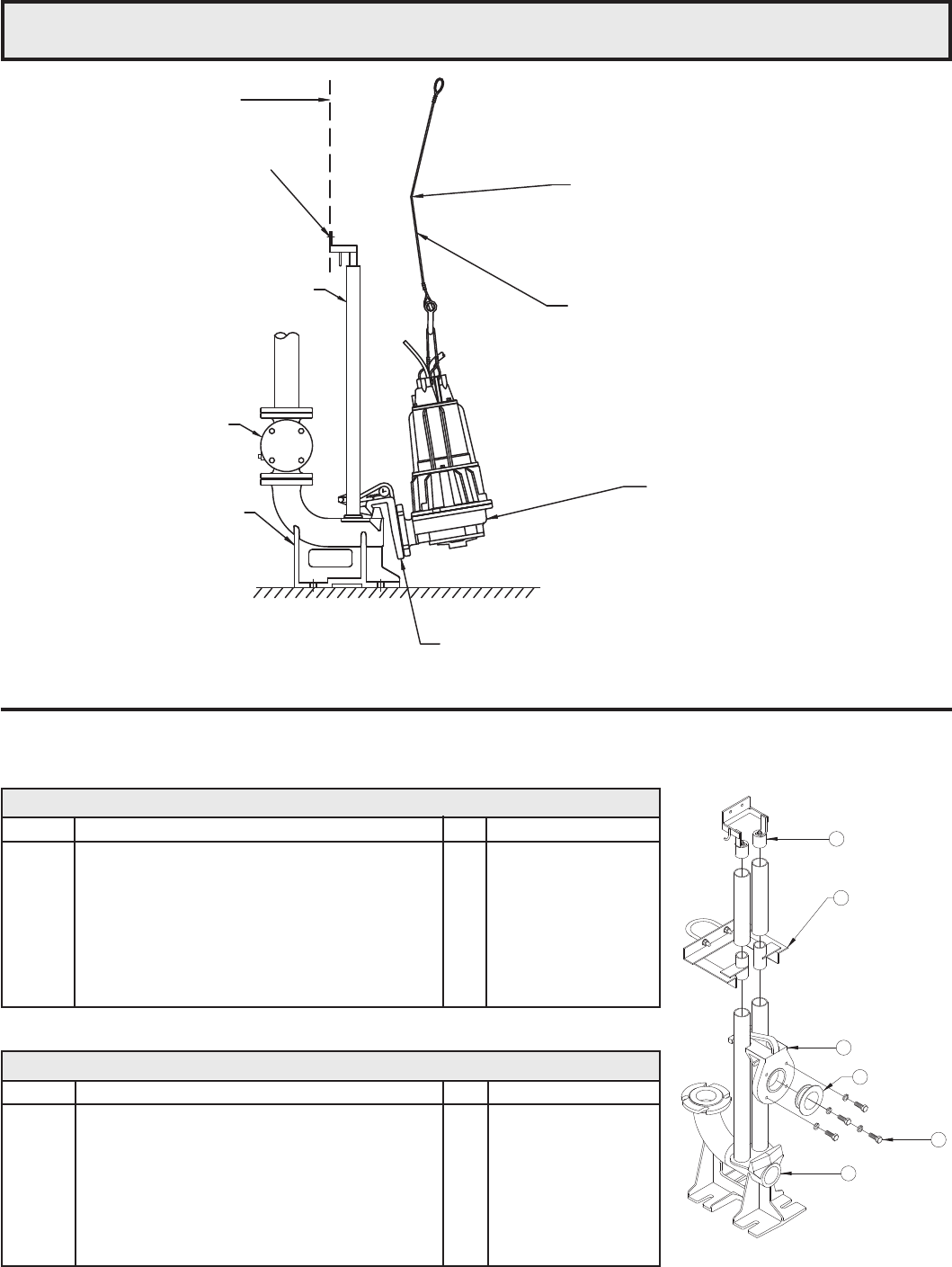
INSTALLING PUMP AND DISCONNECT
Position pump so the guide rails are captured by the mounting plate. Slowly lower the pump down the guide rails
with the pump tilted at a slight angle protecting the Buna-N gasket as the plate engages the base elbow. Refer to
drawing on next page.
If the pump is supported from beneath with concrete blocks or extended legs on the pump base, make certain the mounting
plate gasket is sufciently compressed for sealing. The cantilevered weight of the pump is required for compressing and
sealing the mounting plate gasket against the face of the discharge elbow.
After lowering the pump down the guide rail, secure the upper end of the lifting cable to the top rail support to keep it from
falling into the pit.
Order intermediate stabilizer for basin depths greater than 15 feet (20 feet for the 2.5"/3" systems).
© Copyright 2011 Zoeller Co. All rights reserved.
Zoeller Engineered Products 2.5/3" Guide Rail System
Uses 2" I.P.S. guide rails and pull cable or chain (not furnished)
2.5/3" Systems - P/N 39-0094 and 39-0095
Item No. Description Qty. 1/01 thru current
Parts List For 39-0095 - 2.5/3" Guide Rail System (Non-Sparking Systen)
1 Epoxy Coated Cast Iron Discharge Elbow 1 014447
2 Bronze Mounting Plate 1 014139
* 3 Optional S.S. Intermediate Stabilizer
for Depths Greater Than 20' 1 014807
4 S.S. Upper Guide Rail Bracket 1 014141
5 Buna N Gasket 1 014142
6 Stainless Steel Hardware -- Consult Factory
Parts List For 39-0094 - 2.5/3" Guide Rail System
Item No. Description Qty. 1/01 thru current
1 Epoxy Coated Cast Iron Discharge Elbow 1 014447
2 Epoxy Coated Cast Iron Mounting Plate 1 013575
* 3 Optional S.S. Intermediate Stabilizer
for Depths Greater Than 20' 1 014807
4 S.S. Upper Guide Rail Bracket 1 014141
5 Buna N Gasket 1 014142
6 Stainless Steel Hardware -- Consult Factory
* Order P/N 39-0096 for pit depths greater than 20 feet.
*
1
2
3
4
6
5
ZEPA0535
CHECK VALVE
S.S. OR GALV. STL.
LIFTING CABLE
(OPTIONAL)
FLANGED RAIL SYSTEM
(2) 2 INCH SCH. 40, S.S. OR GALV.
STEEL PIPE (BY OTHERS)
TWO 1/2 HOLES
DOOR FRAME
REF. PLANE
REMOVE LEGS FROM 7100 SERIES
GRINDER PUMP BEFORE PLACING
ON RAIL SYSTEM.
SLIGHT TILT TO PUMP TO
PROTECT THE SEAL AS
INSTALLING.
AS LOWERING PUMP IN TO PLACE
PRESS FORCE ON CABLE TO TILT
PUMP SLIGHTLY AS IT ENGAGES TO
DISCONNECT ELBOW.
ZEPA0615
* Not replaceable - order complete discharge elbow.
** Optional: order P/N 6039-0021or pit depths greater than 15 ft.
© Copyright 2011 Zoeller Co. All rights reserved.
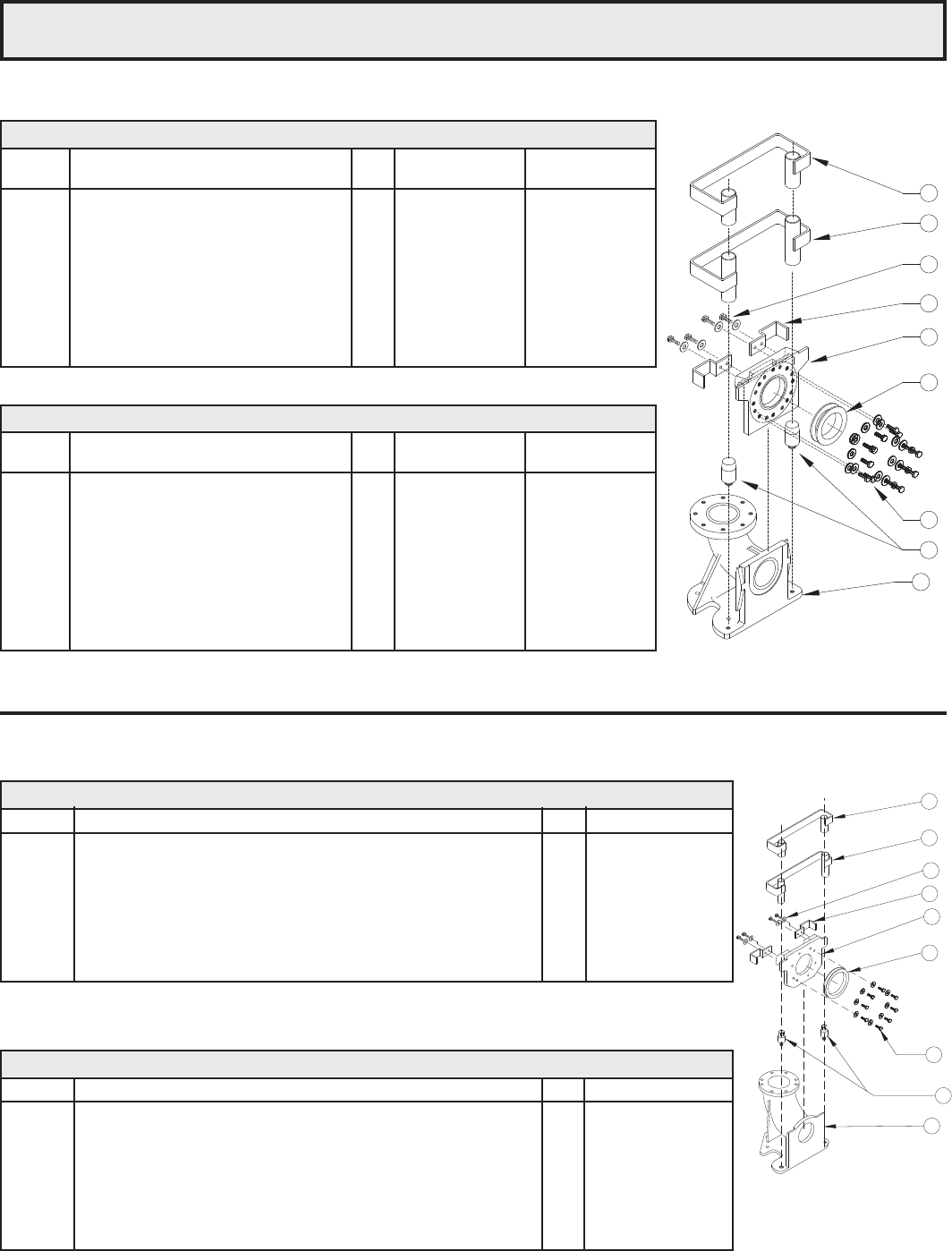
Zoeller Engineered Products 4" and 6" Guide Rail System
6" Systems - P/N 6039-0072 and 6039-0073
ZEPA0496
Parts List For 6039-0073 - 6" Guide Rail System (Non-Sparking Systems)
Item No. Description Qty. 1/00 thru current
1 6" Epoxy Coated Cast Iron Discharge Elbow 1 011282
2 Epoxy Coated Cast Iron Lower Guides 2 011265
3 Bronze Mounting Plate 1 011280
4 Upper Guide Rail Bracket 1 006665
** 5 Optional Intermediate Stabilizer for systems over 15’ deep 1 007513
6 Bronze Guide Brackets 2 006964
7 Buna N Gasket 1 006664
8 Stainless Steel Hardware -- Consult Factory
Parts List For 6039-0072 - 6" Guide Rail System
Item No. Description Qty. 1/00 thru current
1 6" Epoxy Coated Cast Iron Discharge Elbow 1 011282
2 Epoxy Coated Cast Iron Lower Guides 2 011265
3 Cast Iron Mounting Plate 1 011278
4 Upper Guide Rail Bracket 1 006665
** 5 Optional Intermediate Stabilizer for systems over 15’ deep 1 007513
6 Guide Brackets 2 006057
7 Buna N Gasket 1 006664
8 Stainless Steel Hardware -- Consult Factory
**
Uses 2" I.P.S. guide rails and
pull cable or chain (not furnished).
4
5
8
6
3
7
8
2
1
Parts List For 6039-0016 - 4" Guide Rail System
Item No. Description Qty. 2/91 - 2/00 2/00 - Current
Revision A & B Revision C
1 Epoxy Coated C.I. Discharge Elbow *1 006574 006574
2 Lower Guides 2 006055 011265
3 Epoxy Coated C.I. Mounting Plate 1 006572 006572
4 S.S. Upper Guide Rail Bracket 1 006045 006045
** 5 Optional S.S. Intermediate Stabilizer
for systems over 15' deep 1 006050 006050
6 Stainless Steel Guide Brackets 2 006057 006057
7 Buna-N Gasket 1 006041 006041
8 Stainless Steel Hardware -- Consult Factory Consult Factory
Parts List For 6039-0017 - 4" Guide Rail System (Non-Sparking Systems)
Item No. Description Qty. 2/91 - 2/00 2/00 - Current
Revision A & B Revision C
1 Epoxy Coated C.I. Discharge Elbow *1 006574 006574
2 Lower Guides 2 006055 011265
3 Bronze Mounting Plate 1 006961 006961
4 S.S. Upper Guide Rail Bracket 1 006045 006045
** 5 Optional S.S. Intermediate Stabilizer
for systems over 15' deep 1 006050 006050
6 Bronze Guide Brackets 2 006964 006964
7 Buna-N Gasket 1 006041 006041
8 Stainless Steel Hardware -- Consult Factory Consult Factory
4" Systems - P/N 6039-0016 and 6039-0017
ZEPA0119B
4
5
3
7
1
2
6
8
8
**
* NOTE: Discharge Elbow 006574 Revision A & B will have Stainless Steel Lower Guides, and Revision C will have Cast Iron Lower Guides.
** Optional: order P/N 6039-0014 for pit depths greater than 15 ft.
Uses 2" I.P.S. guide rails and pull cable or chain (not furnished)
