269 2 Zoeller Basin Installation Instructions User Manual
537444 2 Zoeller Basin Installation Instructions 537444_2_Zoeller Basin Installation Instructions
537438 2 Zoeller Basin Installation Instructions 537438_2_Zoeller Basin Installation Instructions
537437 2 Zoeller Basin Installation Instructions 537437_2_Zoeller Basin Installation Instructions
537437 2 Zoeller Basin Installation Instuctions 537437_2_Zoeller Basin Installation Instuctions
537445 2 Zoeller Basin Installation Instructions 537445_2_Zoeller Basin Installation Instructions
User Manual: Pump 269 2 Zoeller Basin Installation Instructions
Open the PDF directly: View PDF ![]() .
.
Page Count: 2
© Copyright 2012 Zoeller Co. All rights reserved.
SECTION: 6.10.032
FM2125
0503
Supersedes
1002
NOTICE TO INSTALLER: Instructions must remain with installation.
POLYETHYLENE “INDOOR” APPLICATION
BASIN INSTALLATION INSTRUCTIONS
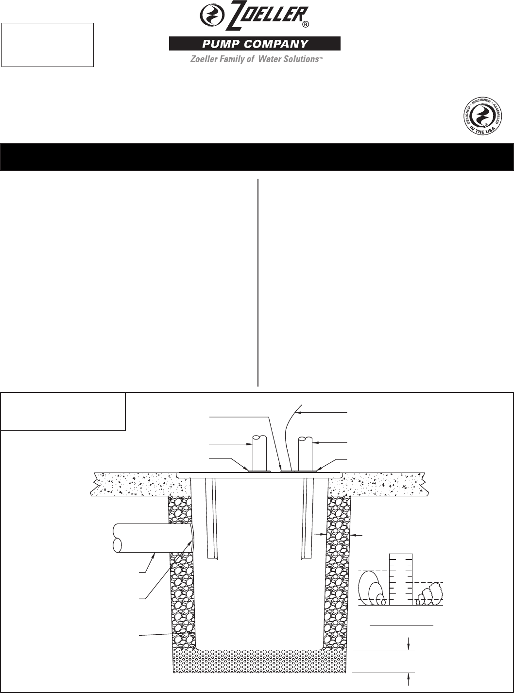
1. Inspect your basin assembly. If the unit has been damaged in shipment
or if parts are missing, contact your distributor before installing.
2. Carefully read all literature to familiarize yourself with details regarding
installation and use. Retain materials for future reference.
3. All installations must comply with all applicable electrical and
plumbing codes, including but not limited to the National Electrical
Code, local, regional and/or state plumbing codes, etc.
4. Dig a hole for the basin. The basin should be located in a very low
trafc area proximate to an appropriate electrical outlet. The hole
should be at least 8” larger in diameter than the basin in order to
leave 4” of backll all the way around the perimeter. A minimum of 4”
of compacted subbase is also required. Backll and subbase should
be 1/8” to 3/4” pea gravel or 1/8” to 1/2” crushed stone.
5. The 4” inlet should be located between the top lip of the basin and
the alarm oat “on” level with a minimum distance of 24 inches
between the oor of the basin and inlet. Determine the location of the
inlet based upon your inlet pipe arrangement. The inlet must be used
with 4” pipe. It should be installed on the side of the basin opposite
the oat switches. To install a 4” cast iron inlet hub, use a 4” holesaw
to drill into the side of the basin at the correct elevation. Center the
hub inner diameter with the hole in the basin. Attach the hub to the
side of the basin using the sealant and hardware provided. To install
a pipe seal, use a 5” holesaw to drill into the side of the basin at the
correct elevation. Insert the pipe seal from the outside of the basin.
6. The cover bolts should be installed into their threaded inserts to
prevent damage to the threads during the nal stages of installation.
7. Carefully set the basin in the hole and connect the 4” inlet pipe. If
using a cast iron hub, seal the pipe to the ange with approved
caulk or gasket. If using a pipe seal, use liquid soap as a lubricant
if necessary. Backll around the basin with specied media. Care
should be taken not to damage components or leave voids when
backlling. Finish grade of oor should be poured in place around
the top 6” of the basin assembly.
8. Clean any debris out of the basin.
FINISHED FLOOR
CRUSHED ROCK
1/4"
PEA GRAVEL
3/4"
1/2"
1"
BACK FILL MATERIAL REQUIREMENTS
DISCHARGE GROMMET
DISCHARGE PIPE
PUMP POWER CORD
VENT GROMMET
VENT PIPE
ELECTRIC CORD GROMMET
POLY BASIN
AS REQUIRED PER
ENGINEER'S SPECIFICATION
GROMMET OR
CAST IRON HUB
INLET PIPE
MINIMUM 4" BACKFILL MATERIAL
SEE REQUIREMENTS BELOW
MINIMUM 4" COMPACTED SUB-BASE
SK2279
Record the model number of the
Zoeller Basin Assembly here:
31-_ _ _ _
Product information presented
here reects conditions at time
of publication. Consult factory
regarding discrepancies or
inconsistencies.
MAIL TO: P.O. BOX 16347 • Louisville, KY 40256-0347
SHIP TO: 3649 Cane Run Road • Louisville, KY 40211-1961
(502) 778-2731 • 1 (800) 928-PUMP • FAX (502) 774-3624
visit our web site:
www.zoeller.com
®
Your Peace of Mind is Our Top Priority
®
© Copyright 2012 Zoeller Co. All rights reserved.
FIBERGLASS “OUTDOOR” APPLICATION
1.
Inspect your basin assembly.
If the unit has been damaged
in shipment or if parts are missing, contact your distributor before
installing.
2.
Carefully read all literature
to familiarize yourself with details
regarding installation and use. Retain materials for future reference.
3. All installations must comply with all applicable electrical and
plumbing codes, including but not limited to the National Electrical
Code, local, regional and/or state plumbing codes, etc.
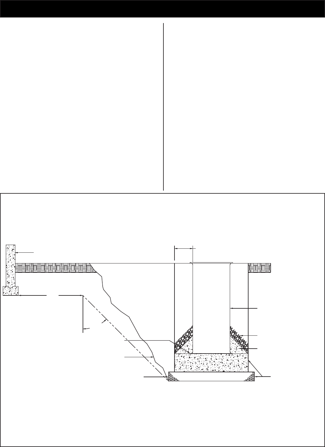
4. Dig a hole for the basin. The hole should be at least 24” larger in
diameter than the basin diameter to provide 12” of backll all around
and deep enough to provide either 12” of compacted backll or 6”
when a concrete pad is required. Ensure the removable cover
extends above the nished grade line and the grade slopes away
from the unit. Backll and subbase should be 1/8” –3/4” pea gravel
or 1/8” –1/2” crushed stone.
5.
Note: Care must be taken when excavating in order to avoid
underground utilities and disturbance of existing structure
foundations. The hole should be located at least ten feet
from adjacent structures. Additional distance may be re-
quired to sufciently locate the basin outside of the loading
area of the adjacent structures.
6. Determine the location of the inlet based upon your inlet pipe arrange-
ment. The inlet must be used with 4” pipe. It should be installed on
the side of the basin opposite the oat switches. To install a 4” cast
iron inlet hub, use a 4” holesaw to drill into the side of the basin at
the correct elevation. Center the hub inner diameter with the hole in
the basin. Attach the hub to the side of the basin using the sealant
and hardware provided. To install a pipe seal, use a 5” holesaw to
drill into the side of the basin at the correct elevation. Insert the pipe
seal from the outside of the basin.
7. The bottom of the excavation can now be back lled and compacted.
Set the basin in the hole and connect the 4” inlet pipe. If using a cast
iron hub, seal the pipe to the ange with approved caulk or gasket.
If using a pipe seal, use liquid soap as a lubricant if necessary.
8. The cover bolts should be installed into their threaded inserts to
prevent damage to the threads during the nal stages of installation.
9. Pouring a concrete anchor around system can now be completed.
Basin should be lled with water when pouring concrete to minimize
movement of the system. Backll around basin with specied media.
Care should be used to avoid damaging components or leaving voids
when back lling.
10.
Note: Venting can be installed on basin cover as necessary
according to all applicable national, state, and local plumb-
ing codes.
11. Clean any debris out of the basin.
FINISHED GRADE
ADJACENT STRUCTURE, FOUNDATION
FOOTING OR PROERTY LINE
12" MINIMUM BACKFILL
COMPACTED TO A MINIMUM
SOIL MODULUS OF 700 PSI
COMPACTED SUB-BASE AND/OR
CONCRETE SLAB AS PER
ENGINEER'S SPECIFICATION
BASIN ANTI-FLOATATION DEVICE
SLOPE AND SIZE OF EXCAVATION
AS PER OSHA AND ENGINEER'S
SPECIFICATION. IN THE ABSENCE
OF THESE. CONSIDER CONDITION
OF SOIL. DEPTH OF EXCAVATION
AND SAFETY CONSIDERATIONS.
COMPACTED SUB-BASE
MINIMUM 12" OR 6"
WHEN USED WITH CONCRETE
HOLD-DOWN PAD
CONCRETE GROUT AS
REQUIRED PER ENGINEER'S
SPECIFICATION
BACKFILL MATERIAL
FIBERGLASS BASIN AS
REQUIRED PER
ENGINEER'S SPECIFICATION
5'-0"
MINIMUM
45°
MINIMUM
SK2280
