48297 2 Taco Hec Instructions 102 075 User Manual
User Manual: Pump 48297 2 Taco Hec-2 Instructions
Open the PDF directly: View PDF ![]() .
.
Page Count: 8
Instruction Sheet 102-435
SUPERSEDES: November 1, 2011 EFFECTIVE: April 1, 2012
Plant ID No. 001-4049
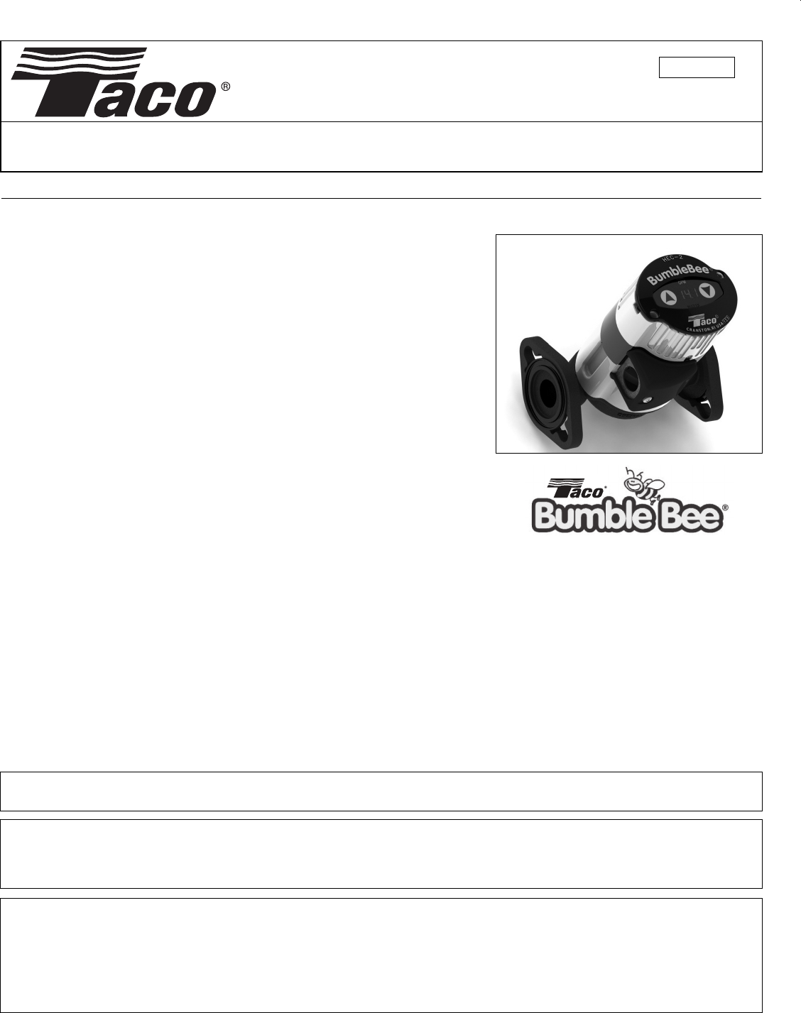
HEC-2 – Variable Speed, ECM High-Efficiency Circulator
DESCRIPTION:
The HEC-2 BumbleBee is a multi-function, variable speed wet rotor circulator with an
ECM, permanent magnet motor. Its high efficiency motor reduces power consump-
tion by up to 85% compared to equivalent AC permanent split capacitor circulators.
APPLICATION:
• Maximum operating pressure: 125 psi (862 kPa)
• Maximum water temperature: 230°F (110ºC)
• Electrical specifications:
Voltage: 115/230, 50/60 Hz, single phase
Operating power range: 9W - 42W
Amp rating: 0.67/0.39
• HEC-2 is provided with a cast iron casing and should be used for closed
loop systems only.
• Taco circulator pumps are for indoor use only – employer uniquement a
l’interieur.
• Acceptable for use with water or maximum of 50% water/glycol solution.
FEATURES:
• Programmable PC board with LED display and 3 operating modes:
CP – Constant Power Mode (Fixed Speed) (allows for 4 fixed circulator speeds, [SP1, SP2, SP3, SP4])
SP – Set Point Mode (Variable Speed, fixed supply temperature, 65°F - 220°F)
dE – “Delta T” Mode (Variable Speed, fixed temperature differential (∆
T)
range from 5°F - 50°F)
• Can be wired to a Taco ZVC Zone Valve Control or SR Switching Relay for ON/OFF operation.
• Sensor kit includes one long and one short sensor with two tie wraps.
• Integral Flow Check (IFC) is included in carton. Simply press into discharge flange if required.
• Swivel-flanged casing provides 360° rotation mounting flexibility.
• LED displays operating mode (CP, SP, dE), power usage (WATTS) and flow (GPM), alternating every 5 seconds.
1. Location:
The circulator can be installed on the supply or return side of the boiler but for best system performance, it should always pump
away from the expansion tank. Sensor location is very important. Refer to Diagrams No.1 and No. 2.
INSTALLATION:
WARNING: Do not use in swimming pool or spa areas. Pump has not been investigated for these applications.
AVERTISSEMENT: Ne pas utiliser dans une piscine ou un spa. La pompe n'a pas été étudiée pour ces applications.
CAUTION: The addition of petroleum based fluids or certain chemical additives to systems using TACO equipment
voids the warranty. Consult factory for fluid compatibility.
ATTENTION: L'ajout de liquides à base de pétrole ou de certains additifs chimiques à des systèmes utilisant un
équipement TACO annule la garantie. Consultez le fabricant pour connaître la compatibilité de liquides.
CAUTION: Installations at elevations over 5000 feet must have higher fill pressure of 20 psi minimum to prevent
pump cavitation and flashing. Premature failure may result. Adjust expansion tank pressure to equal fill pressure. A
larger size expansion tank may be required.
ATTENTION: Des installations à des altitudes de plus de 1600 mètres doivent présenter une pression de remplissage
plus élevée de 20 psi au minimum afin d'éviter toute cavitation ou flashing de la pompe. Une défaillance prématurée
peut en résulter. Réglez la pression du réservoir d'expansion de façon qu'elle soit égale à la pression de remplis-
sage. Un réservoir d'expansion d'une taille supérieure peut être nécessaire.
2
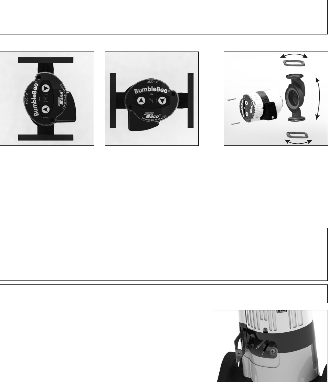
ACCEPTABLE MOUNTING POSITIONS CASING/FLANGE ROTATION
To rotate the casing, remove the two motor
screws and spin the casing 180° to the
reverse flow direction. Reattach the two
screws. (5⁄32"allens wrench required.)
4. Wiring the circulator:
Disconnect AC power supply. Remove terminal box cover. Connect hot wire to
black lead and neutral wire to white lead. Connect ground wire to green ground
screw. Replace terminal box cover.
WARNING: Use supply wires suitable for 90°C,
AVERTISSEMENT: Employer des fils d’alimentation adeqauts pour 90°C.
2. Mounting position:
Circulator must be mounted with the motor in the horizontal position. See diagrams below for acceptable motor mounting orien-
tations. Swivel flanges allow 360° rotation of pump.
3. Fill the system with tap water or a maximum of 50% propylene-glycol and water solution:
The system must be filled before operating the circulator. The bearings are water lubricated and should not be allowed to operate
dry. Filling the system will result in immediate lubrication of the bearings. It is always good practice to flush a new system of for-
eign matter before starting the circulator.
Electrical box must be located below or on right side of motor housing with opening
facing down.
CAUTION: To reduce the possibility of noise transmission, be sure to add vibration dampeners to piping when
mounting circulator to wall or floor joists.
ATTENTION: Pour réduire la possibilité de transmission de bruit, veillez à ajouter des amortisseurs de vibration à la
tuyauterie lors du montage du circulateur sur des chevêtres de mur ou de plancher.
WARNING: Risk of electric shock. This pump is supplied with a grounding conductor and grounding-type attach-
ment plug. To reduce the risk of electric shock, be certain that it is connected only to a properly grounded, ground-
ing-type receptacle. Follow all local electrical and plumbing codes.
AVERTISSEMENT: Risque de choc électrique. Cette pompe est équipée d'un conducteur de mise à la terre et d'une
prise de branchement de type mise à la terre. Pour réduire le risque de choc électrique, veillez à ce qu'elle soit rac-
cordée uniquement à un réceptacle de type mise à la terre proprement mis à la terre. Respectez tous les codes de
plomberie et électriques locaux.
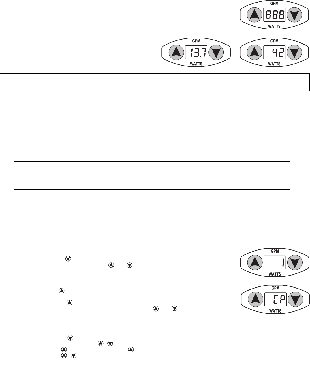
5. Start the circulator:
Note: On start-up, when power is applied to the circulator, the red LED will display “888” for
2 seconds prior to entering the pre-set Operating Mode.
The red LED will display operating mode, “GPM” and “WATTS”,
alternating every 5 seconds.
NOTE: LED displays may vary based on system conditions
and the pumps operating mode.
The HEC-2 is factory preset for “dE” Delta-T Mode at 20°F ΔT. To change operating mode, see “Programming the HEC-2
Circulator”. Operate the circulator for a minimum of 5 minutes immediately after flushing the system to purge remaining air from
the circulator. NOTE: When set in “dE” or “SP” variable speed operating modes, the circulator will always run at full speed
for the first 3 minutes to ensure consistent water temperature for the sensors. Simply power down the pump and restart
for an additional 3 minutes of full speed run time to continue purging. Repeat if necessary.
PROGRAMMING CHART
MODE OPERATING
MODE
MODE
NUMBER
DEFAULT
SETTING
MINIMUM
SETTING
MAXIMUM
SETTING
Constant Power
(Fixed Speed) CP 2 SP4 SP1 SP4
Set Point
(Variable Speed) SP 3 105°F 65°F 220°F
“Delta T” (Δ
T)
(Variable Speed) dE 4 20°F 5°F 50°F
NOTE: Mode Number 1 is used solely to set the Operating Modes – CP, SP, dE.
PROGRAMMING THE HEC-2 CIRCULATOR:
3
1. CP – Constant Power Mode (Fixed Speed):
1.1 Setting the circulator to “CP” Mode:
1.1.1 Press and release the arrow button until the number 1 is displayed on the red LED screen.
1.1.2 Simultaneously press and hold both the and arrow buttons until the number 1 begins to
flash – release the arrow buttons.
1.1.3 Press and hold the arrow button. The current mode will display on the red LED screen. After
5 seconds, the modes will begin to scroll through the mode options. Once the “CP” mode is
displayed, release the arrow button.
1.1.4 To lock the “CP” mode, simultaneously press and hold the and arrow buttons until the
red LED stops flashing. The Constant Power mode is now set and locked.
QUICKSET PROGRAMMING – Constant Power Mode
1. Press and release S – number 1 should display.
2. Simultaneously press and hold buttons – number 1 flashes – release buttons.
3. Press and hold – scroll to “CP” – release .
4. Press and hold arrow buttons until LED stops flashing to save setting.
5. “CP” mode is now locked – proceed to “Verify the circulator is in “CP” mode.
CAUTION: Never run the circulator dry or permanent damage may result.
ATTENTION: Ne laissez jamais le circulateur tourner à sec, des dommages permanents peuvent en résulter.
4
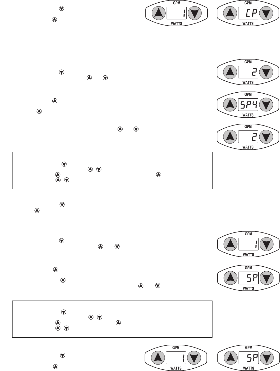
1.2 Verify the circulator is in “CP” Mode:
1.2.1 Press and release the arrow button. The number 1 should
display in red.
1.2.2 Press and hold the arrow button. The number 1 will change
to
“
CP”.
1.3 Setting the speed selection when in “CP” Mode:
1.3.1 Press and release the arrow button until the number 2 is displayed on the red LED screen.
1.3.2 Simultaneously press and hold the and arrow buttons until the number 2 begins to flash
– release the arrow buttons.
1.3.3 Press and hold the button. The default SP4 speed number will begin to flash. After 5 seconds,
the speed number will scroll from SP1 to SP4. Once the desired speed selection is reached,
release the arrow button. The number 2 will reappear on the LED display.
1.3.4 To lock the speed selection, press and hold both and buttons until the number 2 stops
flashing. The speed selection is now set and locked.
1.4 Verify the circulator speed change:
1.4.1 Press and release the arrow button until the number 2 is displayed on the red LED screen.
1.4.2 Press the arrow button and hold. The speed setting will display on the red LED screen.
QUICKSET PROGRAMMING – Constant Power (Fixed Speed) Mode
1. Press and release until number 2 displays.
2. Simultaneously press and hold buttons – number 2 flashes – release buttons.
3. Press and hold – scroll to desired speed selection – release .
4. Press and hold arrow buttons until LED stops flashing to save setting.
5. Speed selection is locked – proceed to “Verify the circulator speed change”.
NOTE: To determine which speed selection is appropriate for your system, please refer to the family of pump
curves on page 8.
2. SP – Set Point Mode:
2.1 Setting the circulator to “SP” Mode:
2.1.1 Press and release the arrow button until the number 1 is displayed on the red LED screen.
2.1.2 Simultaneously press and hold both the and arrow buttons until the number 1 begins to
flash – release the arrow buttons.
2.1.3 Press and hold the arrow button. The current mode will display on the red LED screen. After
5 seconds, the modes will begin to scroll through the mode options. Once the “SP” mode is
displayed, release the arrow button.
2.1.4 To lock the “SP” mode, simultaneously press and hold the and arrow buttons until the
red LED stops flashing. The Set Point mode is now set and locked.
QUICKSET PROGRAMMING – Set Point Mode
1. Press and release S – number 1 should display.
2. Simultaneously press and hold buttons – number 1 flashes – release buttons.
3. Press and hold – scroll to “SP” – release .
4. Press and hold arrow buttons until LED stops flashing to save setting.
5. “SP” mode is now locked – proceed to “Verify the circulator is in “SP” mode.
2.2 Verify the circulator is in “SP” Mode:
2.2.1 Press and release the arrow button until the number 1 is
displayed on the red LED screen.
2.2.2 Press and hold the arrow button and the red LED will dis-
play “SP”.
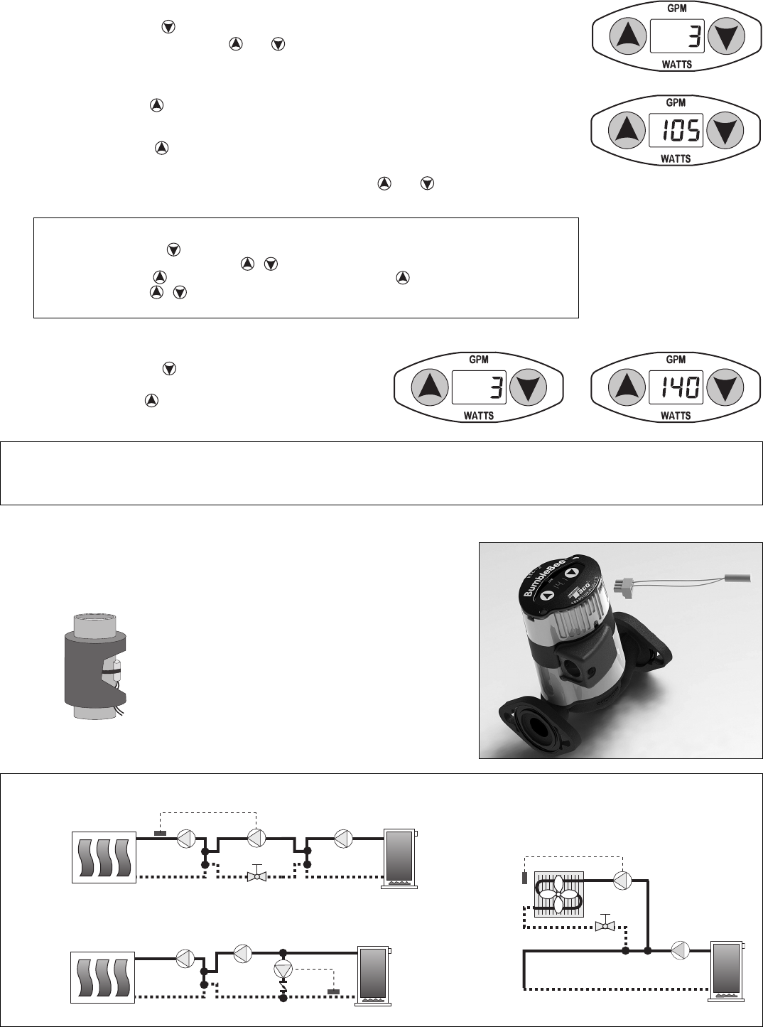
2.3 Setting the Set Point Temperature:
2.3.1 Press and release the arrow button until the number 3 is displayed on the red LED screen.
2.3.2 Simultaneously press and hold the and arrow buttons until the red number 3 begins to flash
– release the arrow buttons.
2.3.3 Press and hold the button and the default set point temperature of 105°F will display and
flash in red. After 5 seconds the temperature will scroll in increments of 1°F. The set point tem-
perature can be set for any temperature from 65°F to 220°F. Once the desired temperature is
reached, release the arrow button. The number 3 will reappear on the LED screen.
2.3.4 To lock the “SP” mode, simultaneously press and hold the and arrow buttons until the
number 3 stops flashing. The set point temperature is now set and locked.
2.4 Verify the circulator Set Point Temperature:
2.4.1 Press and release the arrow button until the number 3 is
displayed on the red LED screen.
2.4.2 Press and hold the arrow button and the red LED will dis-
play the set temperature (for example 140°F).
QUICKSET PROGRAMMING – Set Point Mode Temperature
1. Press and release until number 3 displays.
2. Simultaneously press and hold buttons – number 3 flashes – release buttons.
3. Press and hold – scroll to desired temperature – release S .
4. Press and hold arrow buttons until LED stops flashing to save setting.
5. Temperature is locked – proceed to “Verify the circulator Set Point Temperature”.
Supply
Sensor P1
Diagram No. 1a: Radiant Injection Mixing
2.5 Installing the temperature sensor in “SP” mode:
2.5.1 Attach one sensor to supply line using tie wraps provided.
(See Diagram No. 1a, 1b, and 1c,)
2.5.2 Add insulation to cover sensor.
2.5.3 Wire supply sensor to #3 and #2 (COM) connections on terminal plug.
2.5.4 Press terminal plug into terminal strip on pump.
Supply
Sensor
P1
Diagram No. 1b: Boiler Protection By-Pass
Duct
Supply
Sensor
P1
Diagram No. 1c: Fan Coil Fixed Temperature
5
CAUTION: Do not attempt to remove LED panel from circulator. Serious damage to circulator electronics may result.
ATTENTION: N'essayez pas de retirer le panneau de LED du circulateur. Des dommages sérieux à l'électron-
ique du circulateur peuvent en résulter.
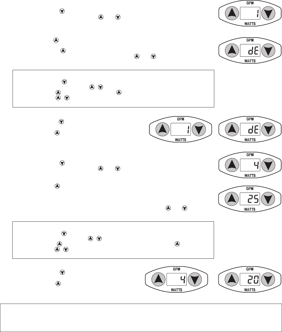
3.4 Verify the circulator “∆
T
” temperature range:
3.4.1 Press and release the arrow button until the number 4 is
displayed on the red LED screen.
3.4.2 Press and hold the arrow button and the set “∆
T
” tem-
perature range will be displayed on the red LED screen (for
example, 20ºF ∆
T)
.
3.3.3 Press and hold the arrow button and the default “∆
T
” temperature of 20°F will begin flash-
ing. After 5 seconds, the number will begin to scroll in increments of 1°F. “∆
T
”
t
emperature
range can be set from 5°F to 50°F. Once the desired “∆
T
” temperature is reached, release the
button. The number 4 will reappear on the LED screen.
3.3.4 To lock the “∆
T
” temperature range, simultaneously press and hold the and arrow but-
tons until the red LED stops flashing. The “∆
T
” temperature range is now set and locked.
QUICKSET PROGRAMMING – “∆
T
” Temperature Range
1. Press and release until number 4 displays.
2. Simultaneously press and hold buttons – number 4 flashes – release buttons.
3. Press and hold – scroll to desired “∆
T
” temperature range – release .
4. Press and hold arrow buttons until LED stops flashing to save setting.
5. Temperature range is locked – proceed to “Verify the circulator “∆
T
” temperature range”.
3. dE – “Delta T” (∆
T)
Mode:
3.1 Setting the circulator to “dE” Mode:
3.1.1 Press and release the arrow button until the number 1 is displayed on the red LED screen.
3.1.2 Simultaneously press and hold both the and arrow buttons until the number 1 begins to
flash – release the arrow buttons.
3.1.3 Press and hold the arrow button. The current mode will display on the red LED screen. After
5 seconds, the modes will begin to scroll through the mode options. Once the “dE” mode is
displayed, release the arrow button and flashing number 1 will reappear.
3.1.4 To lock the “dE” mode, simultaneously press and hold the and arrow buttons until the red
LED stops flashing. The “dE” mode is now set and locked.
3.2 Verify the circulator is in “dE” Mode:
3.2.1 Press and release the arrow button until the number 1 is dis-
played on the red LED screen.
3.2.2 Press and hold the arrow button and the red LED will dis-
play “dE”.
3.3 Setting the circulator “Delta T” (∆
T)
temperature range:
3.3.1 Press and release the arrow button until the number 4 is displayed on the red LED screen.
3.3.2 Simultaneously press and hold both the and arrow buttons until the number 4 begins to
flash – release both arrow buttons.
QUICKSET PROGRAMMING – “dE” Mode
1. Press and release – number 1 should display.
2. Simultaneously press and hold buttons – number 1 flashes – release buttons.
3. Press and hold – scroll to “dE” – release – flashing number 1 will reappear.
4. Press and hold arrow buttons until LED stops flashing to save setting.
5. “dE” mode is now locked – proceed to “Verify the circulator is in “dE” mode”.
6
CAUTION: Do not attempt to remove LED panel from circulator. Serious damage to circulator electronics may
result.
ATTENTION: N'essayez pas de retirer le panneau de LED du circulateur. Des dommages sérieux à l'électron-
ique du circulateur peuvent en résulter.
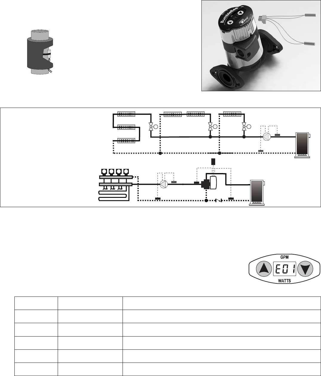
“Delta T” Across a
Series Loop System
Using Zone Valves
M
M
Return
Sensor
M
“Delta T” Across
Multi-Zone Radiant Manifolds
with Loop Actuators
iSeries-R
B
C
A
B
C
A
MMMMMMMM
Outdoor
Sensor
Boiler
Sensor
Diagram No. 2
Supply
Sensor
Supply
Sensor
Return
Sensor
4. Troubleshooting Guide:
The Taco HEC-2 circulator does not require maintenance. Should an error code appear in the
red LED display, please contact the Taco factory at (401) 942-8000 and request a technical
service representative.
4.1 Troubleshooting Error Codes:
Listed below are potential diagnostic error codes which will appear on the HEC-2 Bumble
Bee LED display in case of a malfunction.
EXAMPLE
3.5 Installing the temperature sensors in “dE” Delta T Mode:
3.5.1 Attach one sensor to supply line and one sensor to return line.
Refer to Diagram No. 2 for installation.
3.5.2 Add insulation to cover sensors.
3.5.3 Wire supply sensor to #3 and #2 (COM) connections on terminal plug.
3.5.4 Wire return sensor to #1 and #2 (COM) connections on terminal plug.
3.5.5 Press terminal plug into terminal strip on pump.
ERROR CODE DESCRIPTION CORRECTIVE ACTION
E01 Motor over current Probable debris in rotor. Pump may need to be replaced.
E02 Supply sensor fault Check wiring connections or install new sensor. (Pins 2 and 3)
E03 Return sensor fault Check wiring connections or install new sensor. (Pins 1 and 2)
E04 PC board over temper-
ature Probable malfunction on PC board. Replace pump.
E05 Safety shutdown Probable locked or seized rotor. Occurs after pump tries to start eight times
unsuccessfully. Pump may need to be replaced.
7
LIMITED WARRANTY STATEMENT
Taco, Inc. will repair or replace without charge
(at the company’s option) any Taco HEC-2 High
Efficiency circulator or circulator part which is
proven defective under normal use within three
(3) years from the date of manufacture.
In order to obtain service under this warranty, it
is the responsibility of the purchaser to promptly
notify the local Taco stocking distributor or Taco
in writing and promptly deliver the subject product
or part, delivery prepaid, to the stocking distrib-
utor. For assistance on warranty returns, the
purchaser may either contact the local Taco
stocking distributor or Taco. If the subject prod-
uct or part contains no defect as covered in this
warranty, the purchaser will be billed for parts
and labor charges in effect at time of factory
examination and repair.
Any Taco product or part not installed or operated
in conformity with Taco instructions or which
has been subject to misuse, misapplication, the
addition of petroleum-based fluids or certain
chemical additives to the systems, or other
abuse, will not be covered by this warranty.
If in doubt as to whether a particular substance
is suitable for use with a Taco product or part, or
for any application restrictions, consult the
applicable Taco instruction sheets or contact
Taco at (401-942-8000).
Taco reserves the right to provide replacement
products and parts which are substantially similar
in design and functionally equivalent to the
defective product or part. Taco reserves the right
to make changes in details of design, construc-
tion, or arrangement of materials of its products
without notification.
TACO OFFERS THIS WARRANTY IN LIEU OF
ALL OTHER EXPRESS WARRANTIES. ANY
WARRANTY IMPLIED BY LAW INCLUDING
WARRANTIES OF MERCHANTABILITY OR
FITNESS IS IN EFFECT ONLY FOR THE DURA-
TION OF THE EXPRESS WARRANTY SET
FORTH IN THE FIRST PARAGRAPH ABOVE.
THE ABOVE WARRANTIES ARE IN LIEU OF
ALL OTHER WARRANTIES, EXPRESS OR
STATUTORY, OR ANY OTHER WARRANTY
OBLIGATION ON THE PART OF TACO.
TACO WILL NOT BE LIABLE FOR ANY SPE-
CIAL, INCIDENTAL, INDIRECT OR CONSE-
QUENTIAL DAMAGES RESULTING FROM THE
USE OF ITS PRODUCTS OR ANY INCIDENTAL
COSTS OF REMOVING OR REPLACING
DEFECTIVE PRODUCTS.
This warranty gives the purchaser specific
rights, and the purchaser may have other rights
which vary from state to state. Some states do
not allow limitations on how long an implied
warranty lasts or on the exclusion of incidental
or consequential damages, so these limitations
or exclusions may not apply to you.
COMFORT MADE EASY®
TACO, INC., 1160 Cranston Street, Cranston, RI 02920 Telephone: (401) 942-8000 FAX: (401) 942-2360.
TACO (Canada), Ltd., 8450 Lawson Road, Unit #3, Milton, Ontario L9T 0J8. Telephone: 905/564-9422. FAX: 905/564-9436.
Visit our web site at: http://www.taco-hvac.com
Printed in USA
Copyright 2012
TACO, Inc.
FLOW-GPM
0
1
2
3
4
5
6
7
8
9
10
11
12
13
14
15
16
FLOW-M3/H
0.0
0.5
1.0
1.5
2.0
2.5
3.0
3.5
4.0
4.5
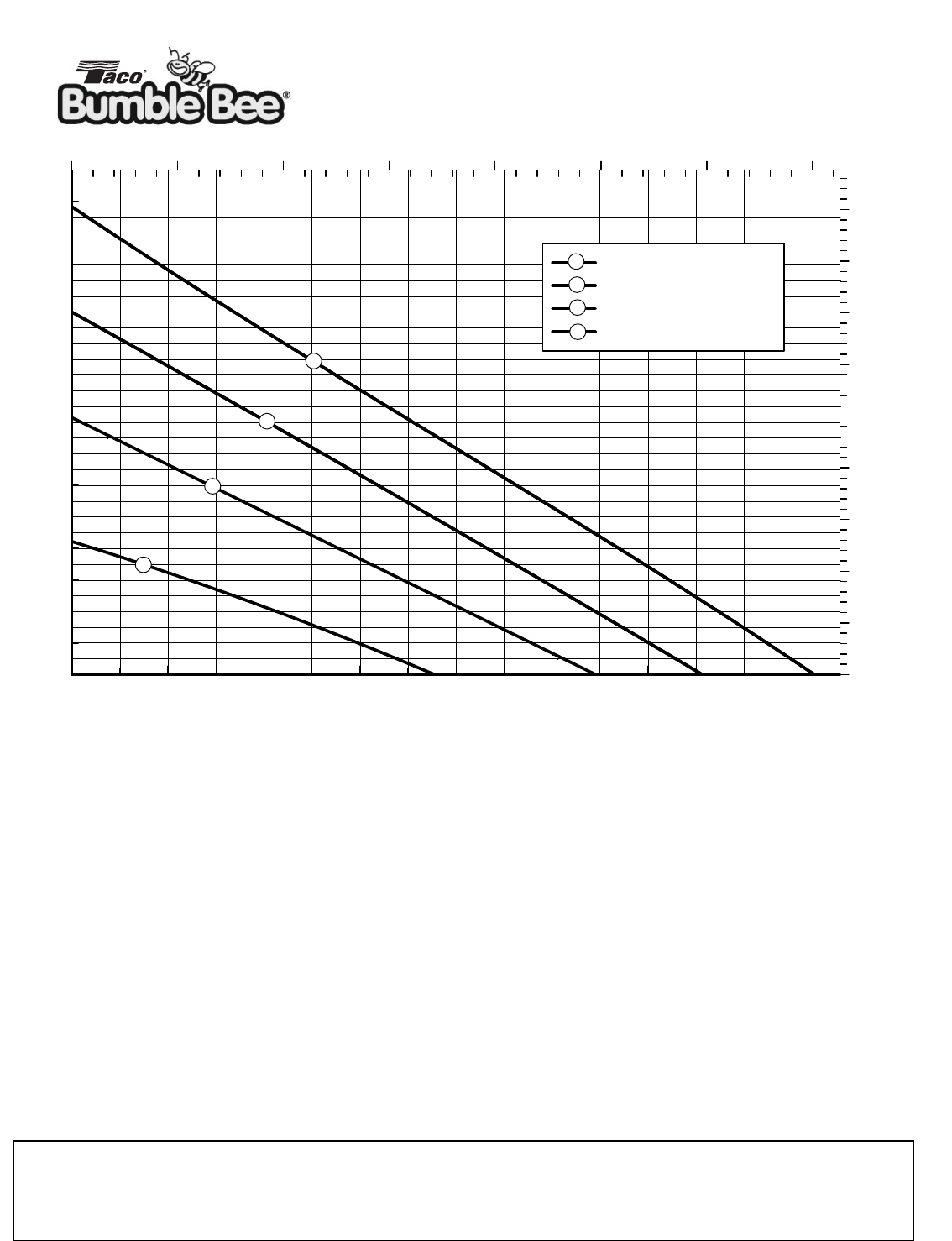
MODEL HEC-2 PERFORMANCE CURVES
TOTAL HEAD - FEET
TOTAL HEAD - METERS
0.0 0.5 1.0 1.5 2.0 2.5 3.0 3.5
0246810 12 14 16
Speed 1 - 9Watts
Speed 2 - 22 Watts
Speed 3 - 32 Watts
Speed 4 - 42 Watts
1
2
3
4
4
3
1
2
8
