49104 3 Berkeley Ps19H S00 Owners Manual S490/Pro Source Tank User
49105 3 Berkeley Ps19S-T02 Owners Manual 49105_3_Berkeley PS19S-T02 Owners Manual
49108 3 Berkeley Ps32-T03 Owners Manual 49108_3_Berkeley PS32-T03 Owners Manual
49109 3 Berkeley Ps35-T05 Owners Manual 49109_3_Berkeley PS35-T05 Owners Manual
49110 3 Berkeley Ps5-S02 Owners Manual 49110_3_Berkeley PS5-S02 Owners Manual
49103 3 Berkeley Ps119-Tr50 Owners Manual 49103_3_Berkeley PS119-TR50 Owners Manual
User Manual: Pump 49104 3 Berkeley Ps19H-S00 Owners Manual
Open the PDF directly: View PDF ![]() .
.
Page Count: 8
OWNER’S MANUAL
Pro-Source
Steel Pressure Tanks
©2003 PRINTED IN U.S.A. S490 (Rev. 12/18/03)
Installation/Operation/Parts
For further operating, installation,
or maintenance assistance:
Call 1-262-728-5551
293 Wright Street
Delavan, WI 53115
Steel Pressure Tank
E
N
G
L
I
S
H
F
R
A
N
Ç
A
I
S
E
S
P
A
Ñ
O
L
®
Safety 2
READ AND FOLLOW
SAFETY INSTRUCTIONS!
This is the safety alert symbol. When you see
this symbol on your pump or in this manual,
look for one of the following signal words and be
alert to the potential for personal injury.
warns about hazards that will cause
serious personal injury, death or major property
damage if ignored.
warns about hazards that can cause
serious personal injury, death or major property
damage if ignored.
warns about hazards that will or can
cause minor personal injury or property damage if
ignored.
The label NOTICE indicates special instructions
which are important but not related to hazards.
Carefully read and follow all safety instructions in
this manual and on pump.
Keep safety labels in good condition.
Replace missing or damaged safety labels.
RULES FOR SAFE
INSTALLATION AND
OPERATION
Read the Owner’s Manual and Rules for Safe
Operation and Installation Instructions carefully.
Failure to follow these Rules and Instructions could
cause serious bodily injury and/or property dam-
age.
Install system according to local codes.
Always test water from well for purity before using.
Check your local health department for testing pro-
cedure.
Before installing or servicing your tank, BE SURE
pump electric power source is disconnected.
BE SURE your pump electrical circuit is properly
grounded.
Remove bleeder orifices, air volume controls or
other air charging devices in existing system.
To prevent possible serious or fatal
injury and/or damage to equipment, system pres-
sure must be less than 100 pounds per square inch
(PSI) under any circumstances. Failure to follow
this instruction can result in tank blowup. If sys-
tem discharge pressure can exceed 100 PSI, install
a relief valve capable of passing the full pump vol-
ume at 100 PSI.
Hazardous pressure. Read owner’s
manual before attempting to install, operate, or
service this tank. To avoid possible equipment fail-
ure, severe injury, and property damage, do not
allow pump, tank, or piping system to freeze.
LIMITED WARRANTY
Sta-Rite Industries, warrants to the original consumer of the products listed below, that they will be free from defects in
material and workmanship for the Warranty Period from the date of original installation or manufacture as noted.
Product Warranty Period
Water Systems Products – jet pumps, whichever occurs first:
small centrifugal pumps, submersible pumps 1 year from date of original installation, or
and related accessories 2 years from date of manufacture
Hydro-Flow Filters 1 year from date of purchase
Signature 2000®Fibrewound Tanks 5 years from date of original installation
Pro-SourceTM Steel Pressure Tanks 5 years from date of original installation
Pro-SourceTM Epoxy-Lined Tanks 3 years from date of original installation
Sump/Sewage/Effluent Products 1 year from date of original installation, or
2 years from date of manufacture
Our warranty will not apply to any product that has been subject to negligence, misapplication, improper installation or
maintenance. In the event a three phase submersible motor is operated with single phase power through a phase con-
verter, or if three-leg ambient compensated, extra-quick trip overload relays of recommended size are not used, our war-
ranty is void.
Buyer’s only remedy and Sta-Rite Industries’ only duty is to repair or replace defective products (at Sta-Rite Industries’
choice). Buyer agrees to pay all labor and shipping charges associated with this warranty and to request warranty ser-
vice through the installing dealer as soon as a problem is discovered. If warranty service is requested more than 30 days
after the Warranty Period has ended, it will not be honored.
STA-RITE INDUSTRIES SHALL NOT BE LIABLE FOR ANY CONSEQUENTIAL, INCIDENTAL, OR CONTINGENT DAM-
AGES WHATSOEVER.
THE FOREGOING WARRANTIES ARE EXCLUSIVE AND IN LIEU OF ALL OTHER EXPRESS WARRANTIES. IMPLIED
WARRANTIES, INCLUDING BUT NOT LIMITED TO THE IMPLIED WARRANTIES OF MERCHANTABILITY AND FITNESS
FOR A PARTICULAR PURPOSE, SHALL NOT EXTEND BEYOND THE WARRANTY PERIOD PROVIDED HEREIN.
Certain states do not permit the exclusion or limitation of incidental or consequential damages or the placing of limitations
on the duration of an implied warranty, therefore, the limitations or exclusions herein may not apply. This warranty sets
forth specific legal rights and obligations, however, additional rights may exist, which may vary from state to state.
Supersedes all previous publications.
Sta-Rite Industries, 293 Wright St., Delavan, WI 53115
General Information 3
GENERAL INFORMATION
All tanks are factory pre-charged with air to 40
pounds per square inch (PSI). When installing tank,
reduce pre-charge to 2 PSI below pump cut-in pres-
sure setting. To do this, bleed air from valve on top
of tank.
NOTICE: Always set pre-charge with NO WATER in
tank.
Check pressure frequently with an accurate tire
pressure gauge until correct pressure has been
reached. For correct pre-charge pressure settings,
see Chart 1, below.
CHART I
NOTICE: Replace and tighten air valve cap if it is
removed for any reason. Failure to replace air cap
may allow loss of air pressure and eventually lead
to tank waterlogging and bladder failure.
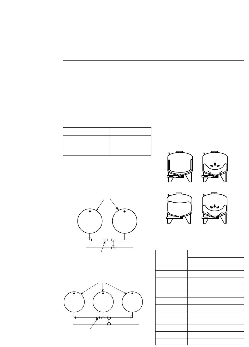
Pre-charged storage tanks can be connected togeth-
er to increase the supply of usable water (draw-
down). Two tanks of the same size will double the
supply and three tanks will triple the supply. See
Figures No. 1A and 1B for typical installations of
this kind.
OPERATING CYCLE
1. Tank nearly empty – air expands filling area
above vinyl bladder
(Fig. 2A).
2. Water begins to enter tank – air is compressed
above bladder as it fills with water (Fig. 2B).
3. Pump-up cycle completed – air now com-
pressed to cut off setting of pressure switch (Fig.
2C).
4. Water being drawn from tank – compressed
tank air forces water out of bladder (Fig. 2D).
5. Bladder completely empty – new cycle ready to
begin (Fig. 2A).
CHART II – Water Yield Per Pump Cycle
(drawdown) in Gallons
Pressure Switch Setting Tank Precharge (PSI)
20-40 PSI 18
30-50 PSI 28
40-60 PSI 38
Pressure Switch Setting (PSI)
Model 20-40 30-50 40-60
PS15-S02 2.2 1.8 1.6
PS15H-S05 2.2 1.8 1.6
PS30-T01 4.8 4.1 3.6
(T)PS42S-T02 6.9 5.8 5.0
(T)PS42T-T02 6.9 5.8 5.0
(T)PS42H-S00 6.9 5.8 5.0
(T)PS75T-T03 11.6 9.8 8.5
(T)PS82T-T05 12.7 10.7 9.3
(T)PS120-T50 18.3 15.5 13.4
(T)PS200-T51 21.4 18.3 16.0
(T)PS220-T52 30.0 26.0 22.0
(T)PS320-TR50 41.3 35.4 31.0
From
Well
To
Service
Tanks
Pressure
Switch
From
Well
To
Service
Tanks
Pressure
Switch
Figure 1A
Figure 1B
Figure 2
WATER
AB
WATER
WATER
CD

Installation 4
Connect system pipe to tank flange. Use plastic or
steel pipe as required. To prevent leaks, use Teflon
tape or Plasto-Joint Stik1on male threads of all
threaded connections to tank.
NOTICE: To be sure that joint is not cross-threaded
and that threads are clean, always make connec-
tions by hand (without sealer) first. After making
sure that threads are clean, remove pipe, add Teflon
tape or Plasto-Joint Stik, and remake connection.
Tighten by hand first; finish with pipe wrench for
tight seal.
NOTICE: When replacing a standard tank in a sub-
mersible pump system, raise pump and discharge
pipe far enough to remove bleeder orifices in dis-
charge pipe and plug tees. When replacing a stan-
dard tank in a jet pump system, remove Air Volume
Control (AVC) and plug AVC port in pump.
In areas where the temperature is high for long
periods of time, the tank pre-charge pressure may
increase. This may reduce the tank drawdown
(amount of water available per cycle). If this occurs,
reduce the pre-charge pressure to two PSI below
the pump cut-in setting of the pressure switch.
It is necessary to flush all air out of the piping sys-
tem and water reservoir portion of the pre-charged
tank. This is required on new installations, pumps
requiring repriming and pumps that have been dis-
assembled for service. Do this as follows:
1. Open faucets furthest from tank and allow
pump to operate.
2. Air in the system will cause a sputtering flow;
allow faucets to run until you have a steady, air
free stream.
3. Open and close faucets repeatedly until you are
sure all air has been removed.
4. If stream does not become steady, air may be
leaking into the system; check for leaks in the
piping on the suction side of the pump.
1Lake Chemical Co., Chicago, Illinois
TO CHECK TANK AIR CHARGE
If drawdown (amount of water that comes out of
tank per pump cycle) decreases significantly, check
as follows:
1. To check air charge in tank, shut off electric
power to pump, open faucet near tank, and
drain completely.
2. At the air valve in top of tank, check air pres-
sure with a standard tire gauge. Air pressure
should be 2 PSI below pump pressure switch
cut-in setting.
3. If the air pressure is more than 2 PSI below the
cut-in setting, add air to the tank. Use an air
compressor or a portable air storage tank.
4. Use soap or liquid detergent to check for air
leaks around air valve. Continuous bubbling
indicates a leak. If necessary, install new core in
air valve. This is the same as those used for
automobile tubeless tires.
TO CHECK PUMP PRESSURE
SWITCH SETTING
1. To check pressure switch setting, disconnect
power to pump at supply panel (but be sure to
leave pressure switch connected to power sup-
ply wires).
2. Remove pressure switch cover.
3. Open a faucet near tank.
4. Bleed pressure down until pressure switch con-
tacts close; immediately close faucet.
5. Check pressure at valve with standard tire
gauge or with pump pressure gauge (if sup-
plied).
6. Pressure gauge should read 2 PSI below pump
cut-in setting (28 PSI for 30-50 switch, 18 PSI
for 20-40 switch, etc.) If not:
A. Adjust switch according to switch manufac-
turer’s instructions.
Maximum Capacity Tank Tank Tank Discharge
Model U.S. Gallons Diameter Height Tapping
PS15-S02 6 12" 16-1/8" 3/4"
PS15H-S05 6 12" 16-1/8"* 3/4"
PS30-T01 14 16" 22-1/4" 1"
(T)PS42S-T02 19 20" 22" 1"
(T)PS42T-T02 19 16" 27-1/2" 1"
(T)PS42H-S00 19 16" 24-5/8"* 1"
(T)PS75T-T03 32 16" 42-3/4" 1"
(T)PS82T-T05 35 20" 32-3/4" 1"
(T)PS120T-T50 50 24" 32-1/2" 1-1/4"
(T)PS200-T51 62 24" 39-1/8" 1-1/4"
(T)PS220-T52 85 24" 50-1/2" 1-1/4"
(T)PS320-TR50 119 24" 68" 1-1/4"
SPECIFICATIONS
* Tank length if Model No. has “H” suffix.
Installation 5
B. Reconnect power supply to pump and pump
up pressure in system.
C. Disconnect power supply to pump again and
re-check switch setting.
D. Repeat until pressure switch starts pump
within ±1 PSI of proper setting.
E. If cut-in setting is too low, system will rattle
or develop water hammer when pump starts.
F. Cut-out setting is not as critical as cut-in set-
ting. Make sure that pump will stop running
in a reasonable time. If it does not, cut-out
setting may need to be adjusted down slight-
ly. Be sure that after readjustment, system
does not rattle or hammer on startup.
7. Re-check tank air pre-charge to be sure it is 2
PSI below pump pressure switch cut-in setting
(see Page 3).
TESTING FOR BLADDER
LEAKAGE
1. Disconnect power to pump.
2. Drain all water from tank bladder by opening
faucet closest to tank.
3. Remove valve cap from valve and release all
pressure possible by depressing valve core.
When air stops coming from valve, remove
valve core to release remaining pressure.
4. Disconnect piping from elbow on tank flange.
5. Carefully turn tank upside down or lay it on its
side.
Retained water in tank may
cause sudden weight shift when lowering.
Support tank so that it cannot fall when being
lowered or inverted.
6. If bladder leaks, water will run out of valve. If
so, replace bladder.
BLADDER REPLACEMENT
To be sure cover flange cannot blow
off of tank, release all air from system before re-
moving nuts from cover flange.
1. Disconnect power to pump.
2. Follow steps 2 through 5 under “Testing For
Bladder Leakage”, above.
3. Remove nuts from tank cover flange. Tap cover
flange to break seal and remove.
4. Bladder will not come out in one piece. Hold
bladder with pliers and cut wherever conve-
nient with single edge razor blade or sharp
knife. Continue holding and cutting until blad-
der is removed.
5. Clean and dry inside of tank.
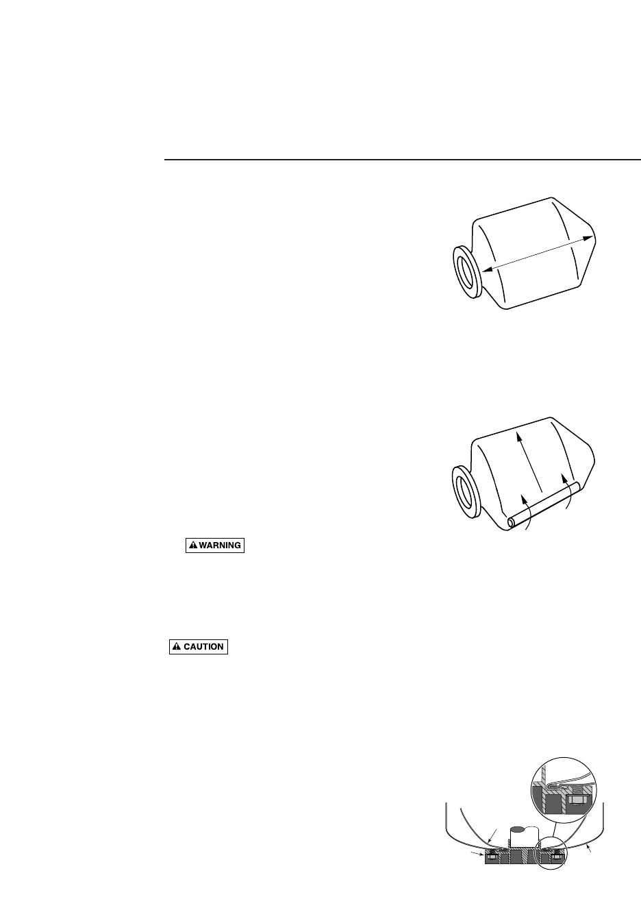
6. Before bladder can be inserted into tank, it must
be tightly rolled up as follows:
A. Place bladder on clean surface with opening
to one end and flatten to force air out. Pull
ends out flat (see Figure 3).
B. To get tightest possible wrap, start on one
side at top and TIGHTLY roll bladder diago-
nally to other side (see Figure 4). To force out
as much air as possible, be sure to roll
toward bladder neck opening.
7. To help insert bladder, sprinkle outside of it
with talcum powder. With tank on its side, push
tightly rolled bladder into tank, hooking bladder
neck ring over edge of tank head.
8. Insert arm in bladder and push sidewalls out-
ward. It is not necessary to remove all wrinkles
from bladder.
NOTICE: Don’t push bladder into tank further
than its own length. In a large tank, bladder can
slip out of reach if pushed too far.
9. Clean tank head sealing surface and lip ring
groove of cover flange.
10. Pull lip ring of bladder through tank opening
and seat it against tank head.
11. Clean sealing surface and groove of cover
flange; place on tank (see Figure 5).
Figure 3 – Force all air out of bladder
Figure 4 – Roll diagonally toward neck
Figure 5 – Proper installation and
seating
Water
Cell
Tank
Wall
Cover
Flange
2822 0 9
2846 0597
2847 0597
Pull ends out flat
Roll Diagonally
Installation 6
NOTICE: Be sure discharge port lines up with
hole in base.
12. NOTICE: Tighten nuts as follows:
A. Hand tighten all nuts.
B. Tighten one nut snug.
C. Tighten opposite nut snug.
D. Proceed, tightening opposite pairs of nuts to
a snug fit.
E. Recheck all nuts, using same pattern. Be sure
all nuts are tight and that you have a good
seal.
NOTICE: Do not overtighten; you may twist
studs off of tank. If you have a torque
wrench, tighten to 85 inch-pounds torque.
13. Stand tank on feet and reconnect piping.
14. Recharge tank to proper air pressure (see Page
4).
15. Prime pump (see pump owner’s manual).
AIR VALVE REPLACEMENT
Hazardous Pressure. To be sure air
valve and core cannot blow out of tank, release all
air pressure from tank before removing valve core
or valve.
1. Disconnect power to pump.
2. Drain ALL water in system by opening faucet
closest to tank.
3. Depress valve core to release ALL air pressure
in tank. When air stops coming out of valve,
remove core from inside of valve to release
remaining pressure.
4. Push air valve back into tank. Be sure to
remove it before reassembling tank.
5. Disconnect piping from tank and turn it on its
side.
6. Remove flange from tank.
7. Push bladder into tank far enough so that you
can get into tank with a dowel rod.
8. Soap the outside of the new valve and mount it
on the end of a piece of 1/4” or 5/16” dowel
rod. Push the valve up past the bladder into its
mounting hole in the top of the tank. Push it
through as far as it will conveniently go; leave
the valve cap on to protect the threads on the
valve.
9. Rap the end of the dowel sharply with a ham-
mer to drive the valve into position. Be sure the
shoulder on the valve seats against the tank
head (the ridge around the valve body should
be all the way through the hole in the tank
head – see Figure 6).
10. Remove the dowel. Make sure the old valve has
been removed from the tank, pull bladder back
over rim of hole in lower tank head, reinstall
flange, stand tank upright and reconnect piping.
11. Recharge tank (see Page 4), turn on power, fill
system, and tank is ready for service.
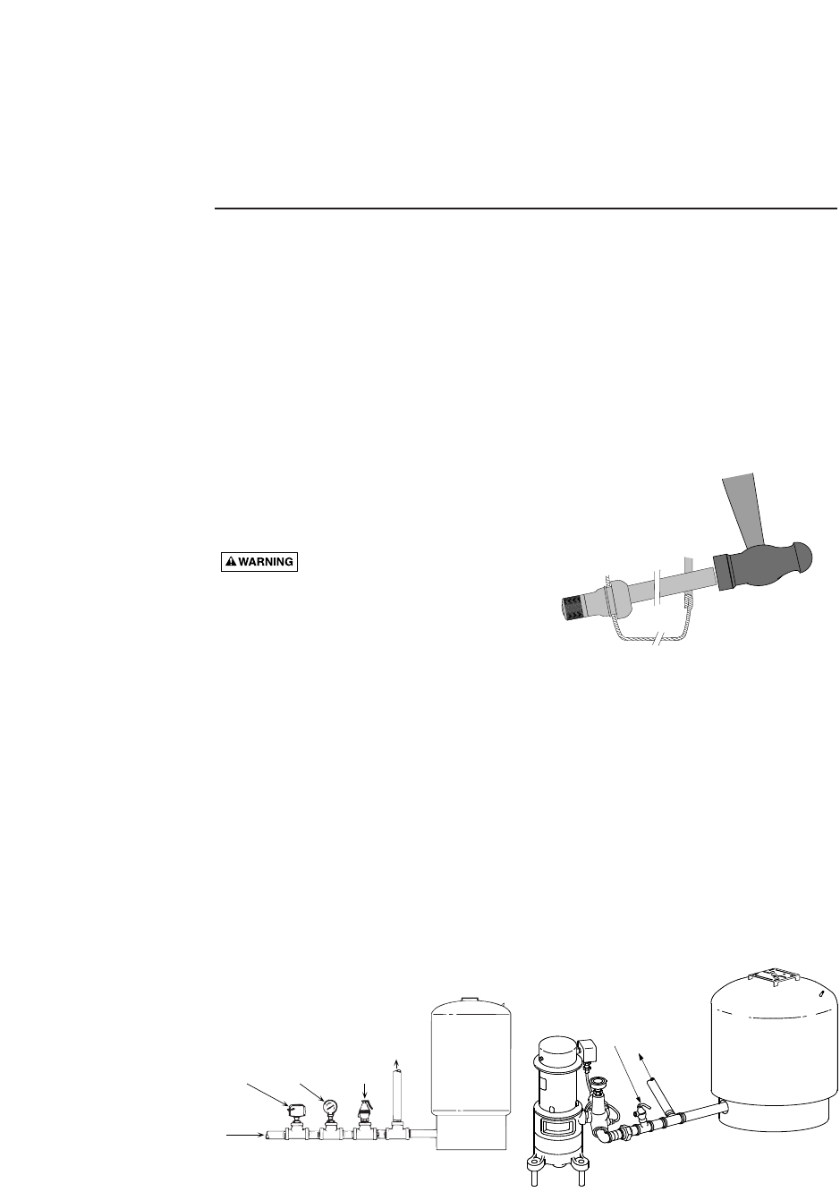
Figure 6 – Tap valve into place
2869 0697
To service
Pressure
Relief Valve
Pressure
Gauge
Pressure
Switch
From Well
160 0893
To Service
Pressure
Relief Valve
Tank with Submersible Pump Tank with Multi-Stage Pump
PIPING CONNECTIONS
SUBMERSIBLE AND MULTI-STAGE INSTALLATIONS
NOTE: When using metal pipe with plastic fittings use only
Teflon tape or Plasto-Joint Stik on male threads.
Repair Parts 7
2
3
4
5
1
1
2
3
2880 0797
4
5
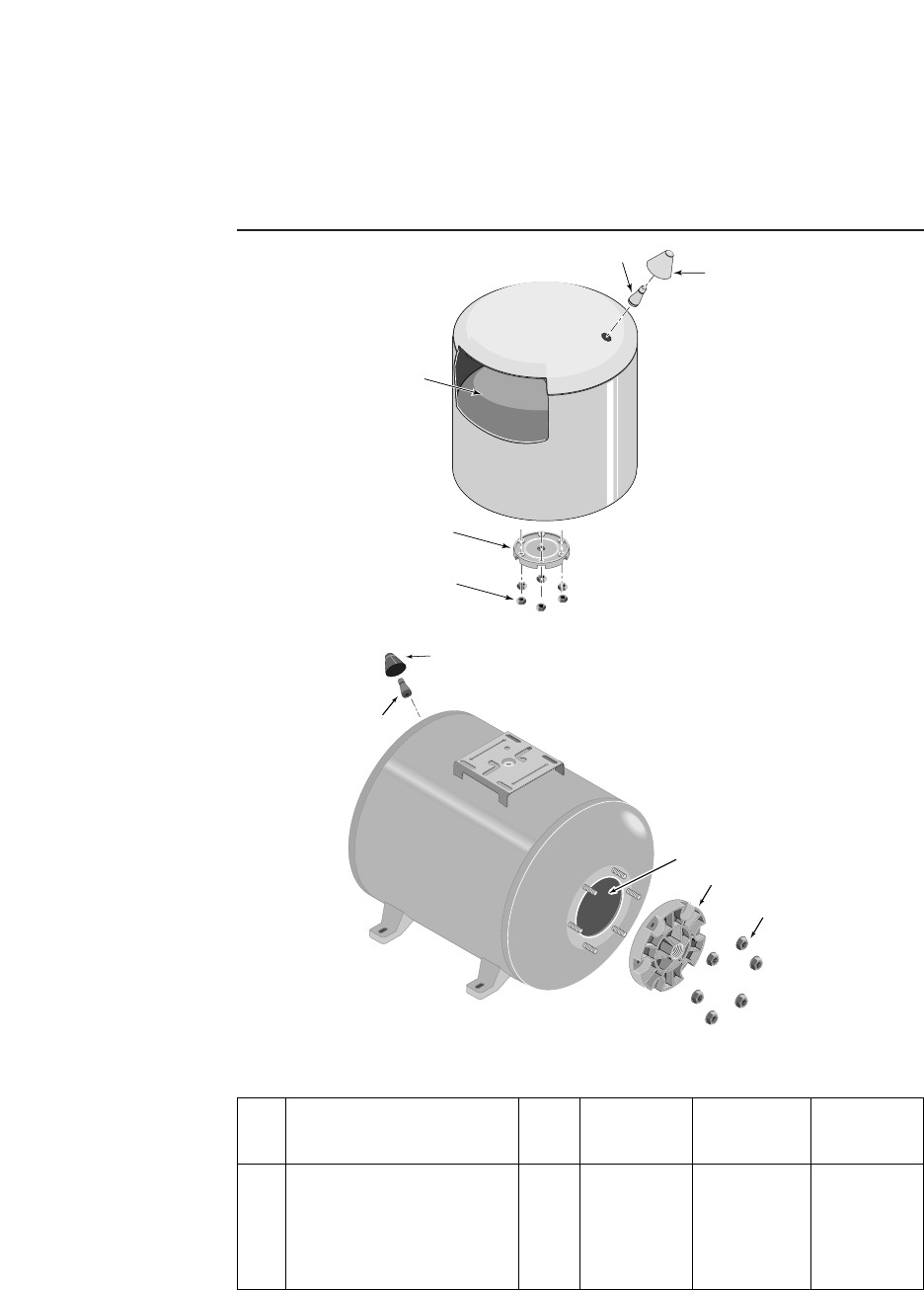
Models PS15-S02
and PS30-T01
Models PS15H-S05
and PS42H-S00
PS15-S02
Key Part No. PS15H-S05 PS30-T01 PS42H-S00
No. Description Used 6 Gal. 14 Gal. 19 Gal.
1Bladder - Vinyl 1 U20-7 U20-13 U20-13
2Cover Flange 1 U31-442P U31-446P U31-446P
3Flanged Nut - 5/16 - 18 Hex. 6 U36-202BT U36-202BT U36-202BT
4Air Valve with Cap 1 U212-160B U212-160B U212-160B
5Air Valve Cover 1 U31-380P U31-380P U31-380P
•Base 1 – U31-505P –
REPAIR PARTS LIST – Pro-Source Tanks
• Not illustrated.
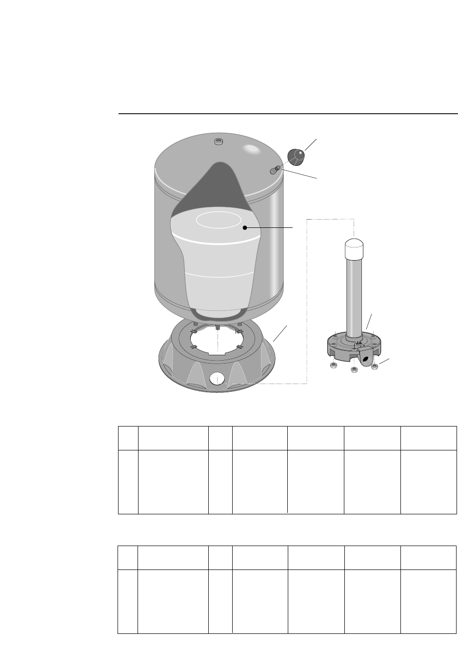
Repair Parts 8
1
2
3
6
5
4
4108 1101
REPAIR PARTS LIST – Pro-Source Tanks
Key Part No. (T)PS42S-T02 (T)PS42T-T02 (T)PS75T-T03 (T)PS82T-T05
No. Description Used 19 Gal. 19 Gal. 32 Gal. 35 Gal.
1Air Valve Cover 1 U31-380P U31-380P U31-380P U31-380P
2Air Valve with Cap 1 U212-160B U212-160B U212-160B U212-160B
3Bladder - Vinyl 1 U20-8 U20-15S U20-15 U20-13L
4Base 1 U31-505P U31-505P U31-505P U31-505P
5Cover Flange 1 U31-446P* U231-460P U231-461P U231-460P
6Flanged Nut
5/16 - 18 Hex 6 U36-202BT U36-202BT U36-202BT U36-202BT
* Does not require Stand Pipe.
* Does not require Stand Pipe.
Key Part No. (T)PS120-T50 (T)PS200-T51 (T)PS220-T52 (T)PS320-TR50
No. Description Used 50 Gal. 62 Gal. 85 Gal. 119 Gal.
1Air Valve Cover 1 U31-380P U31-380P U31-380P U31-380P
2Air Valve with Cap 1 U212-160B U212-160B U212-160B U212-160B
3Bladder - Vinyl 1 U20-10 U20-14 U20-17 U20-20
4Base 1 U31-512P U31-512P U31-512P U31-512P
5Cover Flange 1 U31-447P* U231-482P U231-462P U231-462P
6Flanged Nut
5/16 - 18 Hex 6 U36-202BT U36-202BT U36-202BT U36-202BT
Models
(T)PS42S-T02
(T)PS42T-T02
(T)PS75T-T03
(T)PS82T-T05
(T)PS120-T50
(T)PS200-T51
(T)PS220-T52
(T)PS320-TR50
