535290 4 Franklin Monodrivetroubleshoot Guide User Manual Monodrive Troubleshoot
User Manual: Pump 535290 4 Franklin Monodrivetroubleshoot Guide
Open the PDF directly: View PDF ![]() .
.
Page Count: 2
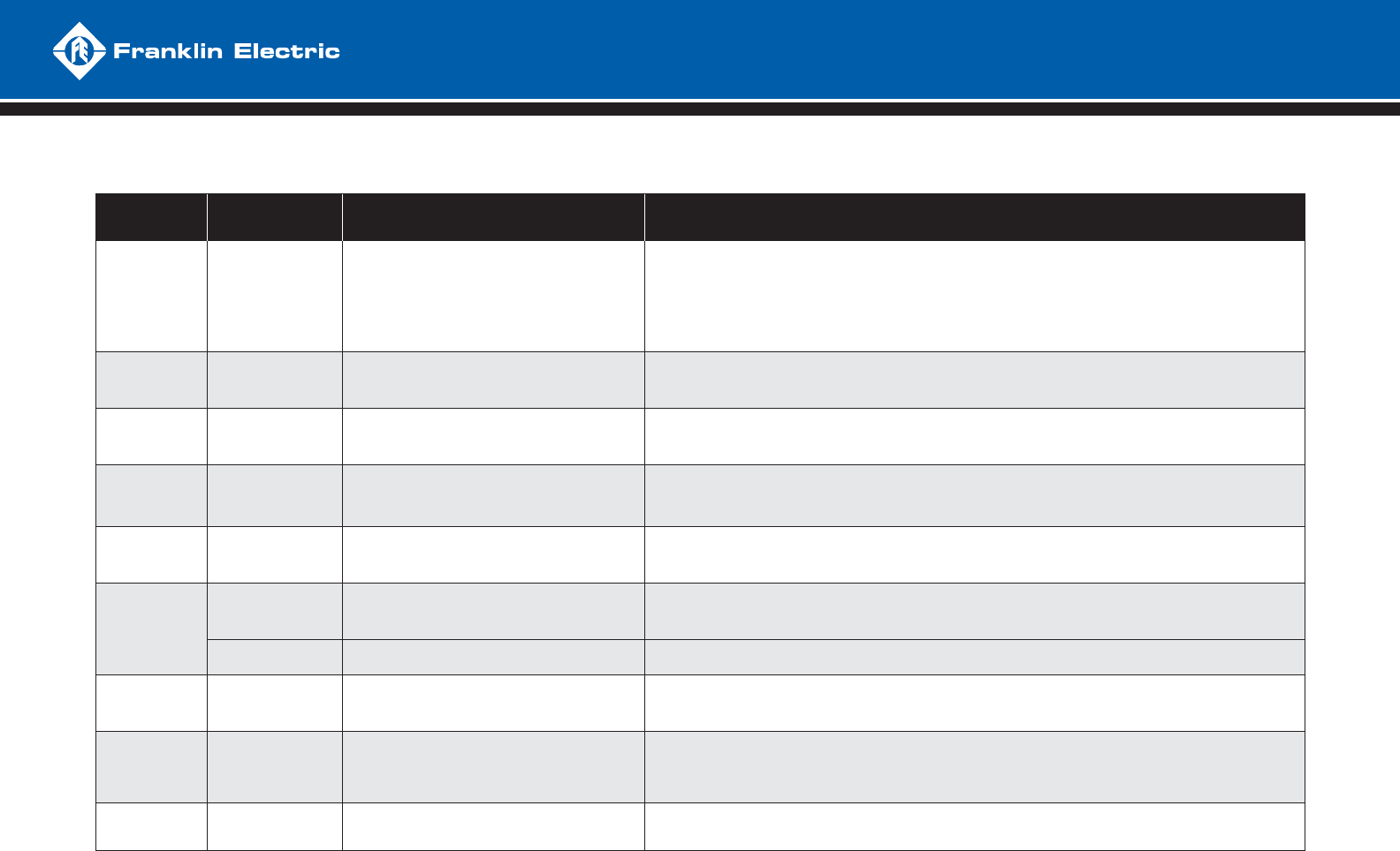
DIAGNOSTIC FAULT CODES
NUMBER OF
FLASHES FAULT POSSIBLE CAUSE CORRECTIVE ACTION
1MOTOR
UNDERLOAD
- Overpumped well
- Broken shaft or coupling
- Blocked screen, worn pump
- Air/gas locked pump
- SubDrive not set properly for pump end
- Frequency near maximum with less than 65% of expected load, 42% if DIP #3 is “on”
- System is drawing down to pump inlet (out of water)
- High static, light loading pump - reset DIP switch #3 to “on” for less sensitivity if not out of water
- Check pump rotation (SubDrive only) reconnect if necessary for proper rotation
- Air/gas locked pump - if possible, set deeper in well to reduce
- Verify DIP switches are set properly
2UNDERVOLTAGE
- Low line voltage
- Misconnected input leads
- Line voltage low, less than approximately 150 VAC (normal operating range = 190 to 260 VAC)
- Check incoming power connections and correct or tighten if necessary
- Correct incoming voltage - check circuit breaker or fuses, contact power company
3LOCKED
PUMP
- Motor and/or pump misalignment
- Dragging motor and/or pump
- Abrasives in pump
- Amperage above SFL at 10 Hz
- Remove and repair or replace as required
4
(MonoDrive &
MonoDriveXT only)
INCORRECTLY
WIRED
- MonoDrive only
- Wrong resistance values on main and start
- Wrong resistance on DC test at start
- Check wiring, check motor size and DIP switch setting, adjust or repair as needed
5OPEN
CIRCUIT
- Loose connection
- Defective motor or drop cable
- Wrong motor
- Open reading on DC test at start.
- Check drop cable and motor resistance, tighten output connections, repair or replace as necessary, use “dry”
motor to check drive functions, if drive will not run and exhibits underload fault replace drive
6
SHORT
CIRCUIT
- When fault is indicated immediately after
power-up, short circuit due to loose connection,
defective cable, splice or motor
- Amperage exceeded 50 amps on DC test at start or SF amps during running
- Incorrect output wiring, phase to phase short, phase to ground short in wiring or motor
- If fault is present after resetting and removing motor leads, replace drive
OVER CURRENT - When fault is indicated while motor is running,
over current due to loose debris trapped in pump
- Check pump
7OVERHEATED
DRIVE
- High ambient temperature
- Direct sunlight
- Obstruction of airfl ow
- Drive heat sink has exceeded max rated temperature, needs to drop below 85 °C to restart
- Fan blocked or inoperable, ambient above 125 °F, direct sunlight, air fl ow blocked
- Replace fan or relocate drive as neccessary
8
(SubDrive300 only)
OVER
PRESSURE
- Improper pre-charge
- Vavle closing too fast
- Pressure setting too close to relief valve rating
- Reset the pre-charge pressure to 70% of sensor setting. Reduce pressure setting well below relief valve rating.
Use next size larger pressure tank.
- Verify valve operation is within manufacturer’s specifi cations.
- Reduce system pressure setting to a value less than pressure relief rating.
RAPID INTERNAL FAULT
- A fault was found internal to drive - Contact your Franklin Electric Service Personnel
Power down, disconnect leads to the motor and power up the SubDrive:
- If the SubDrive does not give an “open phase” fault (5 fl ashes every 2 seconds), then there is a problem with the SubDrive.
- Connect the SubDrive to a dry motor. If the motor goes through DC test and gives “underload” fault (1 fl ash every 2 seconds), the SubDrive is working properly.
TROUBLESHOOTING
QUICK REFERENCE GUIDE
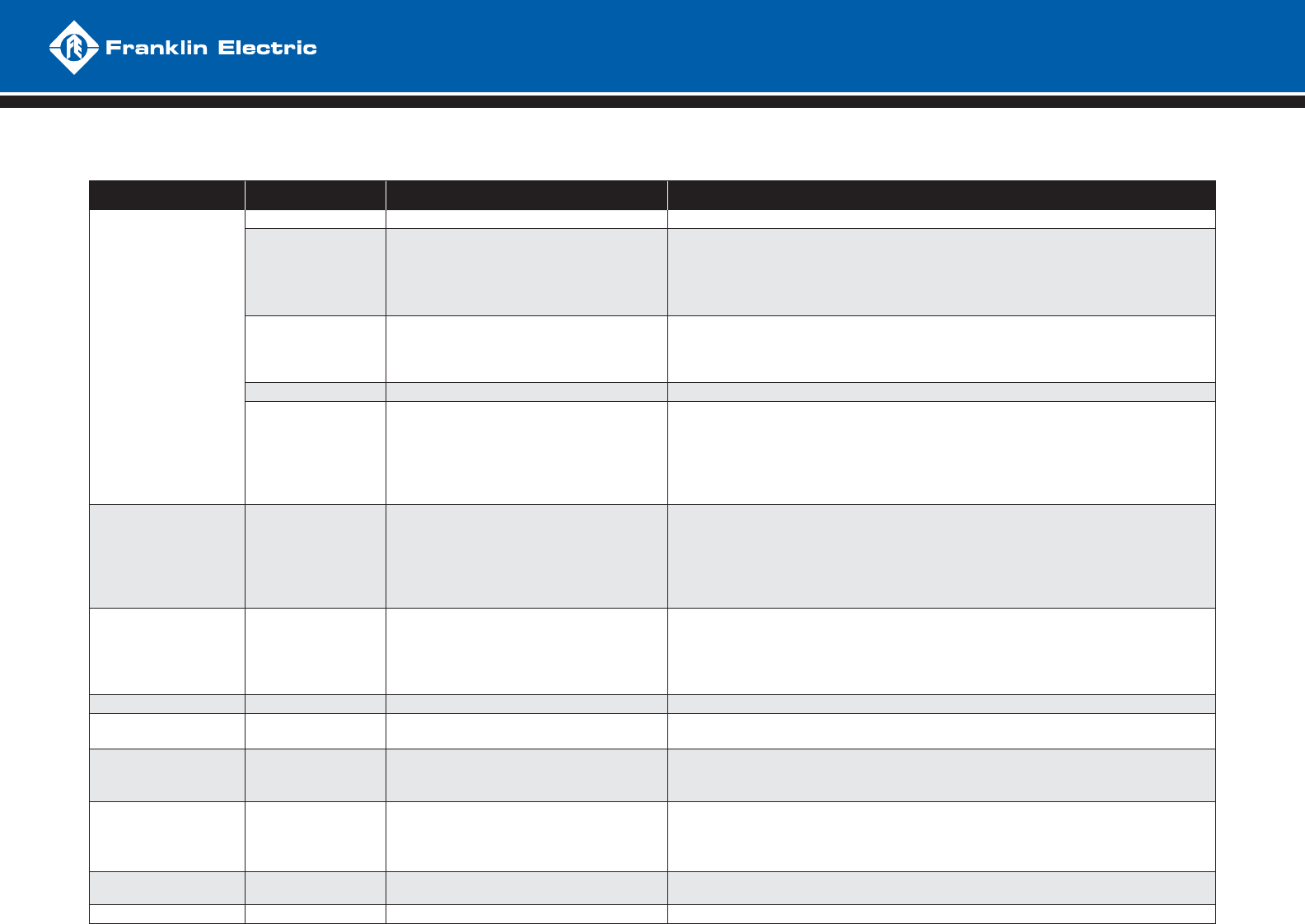
SUBDRIVE TROUBLESHOOTING
CONDITION INDICATOR LIGHTS POSSIBLE CAUSE CORRECTIVE ACTION
NO WATER
NONE - No supply voltage present - If correct voltage is present, replace drive
SOLID GREEN
- Pressure sensor circuit - Verify water pressure is below system set point
- Jumper wires together at pressure sensor, if pump starts, replace sensor
- If pump doesn’t start, check sensor connection at printed circuit board (PCB), if loose, repair
- If pump doesn’t start, jumper sensor connection at PCB, if pump starts, replace wire
- If pump doesn’t start with sensor PCB connection jumpered, replace drive
SOLID RED
OR
SOLID RED
AND GREEN
- Power surge, bad component - Power system down to clear fault, verify voltage, if repetitive, replace drive
FLASHING RED - Fault detected - Proceed to fault code description and remedy
FLASHING GREEN
- Drive and motor are operating
- Loose switch or cable connection
- Gulping water at pump inlet
- Frequency max, amps low, check for closed valve, or stuck check valve
- Frequency max, amps high, check for hole in pipe
- Frequency max, amps erratic, check pump operation, dragging impellers
- This is not a drive problem
- Check all connections
- Disconnect power and allow well to recover for short time, then retry
PRESSURE
FLUCTUATIONS
(POOR REGULATION)
FLASHING GREEN
- Pressure sensor placement and setting
- Pressure gauge placement
- Pressure tank size and pre-charge
- Leak in system
- Air entrainment into pump intake
(lack of submergence)
- Correct pressure and placement as necessary
- Tank may be too small for system fl ow
- This is not a drive problem
- Disconnect power and check pressure gauge for pressure drop
- Set deeper in the well or tank; install a fl ow sleeve with airtight seal around drop pipe and cable
- If fl uctuation is only on branches before sensor, fl ip DIP switch #4 to “on” (07C and newer)
RUN ON
WON’T SHUT DOWN FLASHING GREEN
- Pressure sensor placement and setting
- Tank pre-charge pressure
- Impeller damage
- Leaky system
- Sized improperly (pump can’t build enough head)
- Check frequency at low fl ows, pressure setting may be too close to pump max head
- Verify precharge at 70% if tank size is larger than minimum, increase precharge (up to 85%)
- Verify that the system will build and hold pressure
RUNS BUT TRIPS FLASHING RED - Check fault code and see corrective action - Proceed to fault code description and remedy on reverse side
LOW PRESSURE FLASHING GREEN - Pressure sensor setting, pump rotation,
pump sizing
- Adjust pressure sensor, check pump rotation
- Check frequency at max fl ow, check max pressure
HIGH PRESSURE FLASHING GREEN
- Pressure sensor setting
- Shorted sensor wire
- Adjust pressure sensor
- Remove sensor wire at PCB, if drive continues to run, replace drive
- Verify condition of sensor wire and repair or replace if necessary
AUDIBLE NOISE FLASHING GREEN
- Fan, hydraulic, plumbing - For excessive fan noise, replace fan
- If fan noise is normal, drive will need to be relocated to a more remote area
- If hydraulic, try raising or lowering depth of pump
- Pressure tank location should be at entrance of water line into house
NO LIGHTS NONE - Ribbon cable detached from LED printed
circuit board
- Reattach cable - if cable is attached, replace drive
RFI-EMI INTERFERENCE FLASHING GREEN - See interference troubleshooting procedure
TROUBLESHOOTING
QUICK REFERENCE GUIDE
M1567 07-09
