535538 2 Franklin Pumptec Manual User
User Manual: Pump 535538 2 Franklin Pumptec Manual
Open the PDF directly: View PDF ![]() .
.
Page Count: 8
Owners Manual
Pumptec is a microcomputer based pump
protection device that continuously
monitors motor load and power line
conditions to provide protection against
dry well conditions, waterlogged tanks,
and abnormal line voltage conditions.
Indicator lights provide complete system
status, which can be easily viewed
without removing the cover. Pumptec
interrupts power to the motor whenever
the motor load drops below a preset
level or the load drops quickly.
Pumptec is optimized to work with
Franklin 2 & 3-wire single phase motors
from 1/3 to 1-1/2 HP. An underload (dry
well) adjustment is provided to address
unusual situations.
Protection Features
• Dry Well (Underload)
• Over & Under Voltage
• Rapid Cycle
• Bound Pump
Indicator Lights
• Load
• Voltage
• Status
Remote Control Features
• Over & Under Load Settings
• Over & Under Voltage Settings
• Reset Time Settings
• Fault History (Last 15 Faults)
• System Status Monitor
Other Features
• Heavy Duty Relay
• 115V/230V 50/60Hz Operation
• Alarm Circuit Contacts
Features
Pumptec is a microcomputer based pump
protection device that continuously
monitors motor load and power line
conditions to provide protection against
dry well conditions, waterlogged tanks,
and abnormal line voltage conditions.
Indicator lights provide complete system
status, which can be easily viewed
without removing the cover. Pumptec
interrupts power to the motor whenever
the motor load drops below a preset
level or the load drops quickly.
Pumptec is optimized to work with
Franklin 2 & 3-wire single phase motors
from 0.37 - 1.1kW. An underload (dry
well) adjustment is provided to address
unusual situations.
2
2
Technical Specifi cations:
Model Number 5800020600
Horsepower Rating 1/3 to 1.5
Voltage Rating 115V/230V
Frequency 50/60Hz
Power Consumption 4W
Response Time 3 Seconds
Reset Time 2 to 120 min. (240 min. w/remote)
Motor Type Single Phase Induction Run
Alarm Contact Rating 1 Amp 115V/230V
Over/Under Voltage Time-out 2 minutes
Operating Temperature Range -15ºF to 130ºF
Note:
Pumptec is not designed for use on permanent split capacitor
(PSC) motors.
Dry well protection occurs when pump suction is broken. Deadhead
conditions may not always be detected due to variation in pump
load characteristics
Installation Instructions
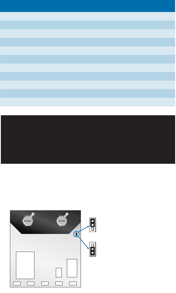
1. Remove the cover from the Pumptec.
2. If you will be running a 1.5HP motor, move the circuit board jumper
to the 1.5HP position as shown in Figure 1.
Timeout
Underload Trip
%SFL
M
o
r
e
S
e
n
s
i
t
i
v
e
¼
90%
80%
60%
40%
70%
60
min
15
min
2
min
120
min
30 min
1/3 HP – 1 HP Setting
(Factory default)
1.5 HP
Setting
Figure 1: Circuit board jumper
for 1.5HP motors
Technical Specications:
Model Number 5800020600
kW Rating 0.37 - 1.1
Voltage Rating 115V/230V
Frequency 50/60Hz
Power Consumption 4W
Response Time 3 Seconds
Reset Time 2 to 120 min. (240 min. w/remote)
Motor Type Single Phase Induction Run
Alarm Contact Rating 1 Amp 115V/230V
Over/Under Voltage Time-out 2 minutes
Operating Temperature Range -15ºF to 130ºF
1. Remove the cover from the Pumptec.
2. If you will be running a 1.1kW motor, move the circuit board jumper
to the 1.1kW position as shown in Figure 1.
1/3HP – 1HP (0.37 - 1.1kW)
Setting (Factory default)
1.5HP (1.1kW)
Setting
Figure 1: Circuit board jumper
for 1.5HP (1.1kW) motors
3
3
3. Mount the unit in a location convenient for wiring.
4. Turn off power at the AC source.
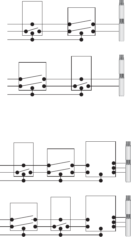
5. Pumptec may be wired upstream or downstream of the control
switch for 2-wire and 3-wire motors. Select an installation option
from fi gures 2A and 2B.
Pumptec
Pumptec
Control
Switch
Control
Switch
Pump
Motor
Pump
Motor
L1
L2
GND
L1
L2
GND
Figure 2A: 2-Wire Motor Installation Options
Pumptec
Pumptec
Control
Switch
Control
Switch
Pump
Motor
Control Box
Control Box
Pump
Motor
L1
L2
GND
L1
L2
GND
Figure 2B: 3-Wire Motor Installation Options
4
4
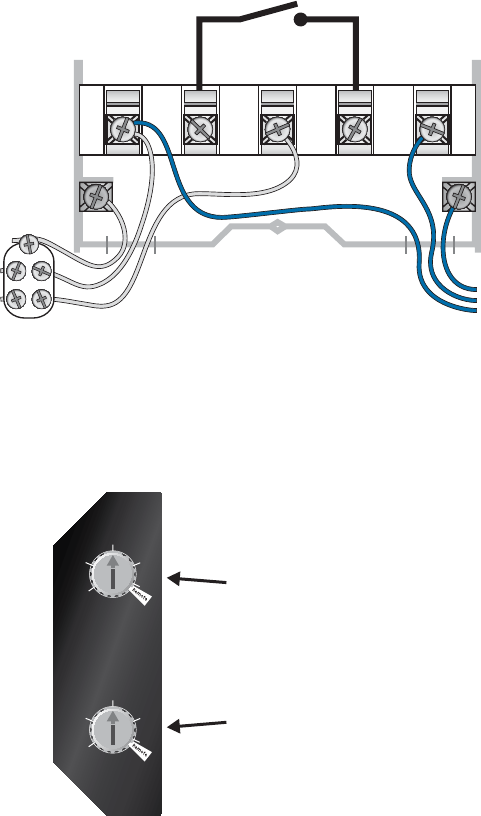
L1 Alarm
115V or 230V
From power source
or control switch
L2 Alarm
(1 A Max.)
Motor
GND
GND
GND
L1
L2
To 2-wire Motor or
3-wire control box
6. Connect wires to the Pumptec as shown in Figure 3. Power is
connected the same way regardless of the line voltage.
Alarm Contacts
Figure 3: Wiring Connections
7. Set the time-out adjustment to the desired position. The factory
setting is 30 minutes, see Figure 4*.
8. The factory underload setting of 70% should not require any
adjustment.
Timeout
Underload Trip
%SFL
M
o
r
e
S
e
n
s
i
t
i
v
e
¼
90%
80%
60%
40%
70%
60
min
15
min
2
min
120
min
30 min
Underload sensitivity
(Full clockwise for remote)
Factory setting = 70%
Reset time adjustment
(Full clockwise for remote)
Factory setting = 30 minutes
Figure 4: Timeout and Trip Sensitivity Settings

5
5
9. Wire in alarm circuit, if desired.
10. Replace cover and secure cover screw.
11. Turn AC power back on.
*Note: If you will be using IR remote control to set the underload and
the time-out settings, set the appropriate adjustment knobs to
the “Remote” position (fully clockwise position). See Figure 4.
The initial remote settings are the same as the factory presets
- 70% for underload and 30 minutes for the underload time-
out. The underload adjustment is preset at the factory to detect
underload (dry well) conditions on most systems. In general,
there is no need to adjust this setting.
For more precise Control
and Data Logging features,
request the free software
for your Palm/Pocket PC.

6
6
Operation
Pumptec has three indicator lights labeled POWER, LOAD and VOLTAGE.
If the Pumptec is connected upstream of the pressure switch, the system
status can be determined from these indicator lights at any time. When
wired down stream of the control switch, no status will be displayed
when the control switch is open.
Power Indicator Light
If solid, the Pumptec has power and the system is idle. In this state, the
motor is not running and the Pumptec is waiting for the control device
(i.e. pressure switch) to close and turn on the motor.
When fl ashing, the system is pumping water and running normally.
Load Indicator Light
When the load light is solid, a dry well (underload) condition has
occurred. The Pumptec will wait the duration of the reset time-out
period before attempting to restart the motor.
A fl ashing load light indicates an overload condition has occurred.
The unit must be manually reset by removing power for 10 seconds.
An overload condition occurs when the motor current has become
excessively high.
Voltage Indicator Light
When the voltage light is solid, an under voltage condition has been
detected. The under voltage trip is factory preset to 203 volts. The
remote control feature may be used to alter the under voltage trip
point.
When the voltage light is fl ashing, an over voltage fault has been
detected. The over voltage trip is factory preset to 253 volts. The remote
control feature may be used to alter the over voltage trip point.
After a voltage fault has occurred, Pumptec will check the line voltage
every two minutes and will reset when the line voltage returns to the
normal range.
Load & Voltage Indicator Lights Flashing
When both the load and voltage indicator lights are fl ashing together
a “Rapid Cycle” condition has occurred. The Pumptec will reset after x
minutes.
* (1/2 second on, 1/2 second off)
t*

7
7
Troubleshooting
Remote Control
A Pocket PC with an infrared port may be used to monitor the motor/
pump system performance and adjust the Pumptec trip points. When
dealing with unusual installations, the system monitor and underload
adjustment remote control features allow quick diagnosis of system
problems.
No Lights
No power is applied to the Pumptec. Check for voltage at the L1 and L2
connections. If Pumptec is wired downstream of the control switch, the
control switch may be open.
Solid Load Light
Pumptec has detected a dry well or underload condition.
A. Make sure the pump and motor are matched correctly.
B. Check for a blocked pump intake or stuck check valve.
C. The coupling between the motor & pump may be stripped.
D. Blocked plumbing or stuck check valve may be causing a
deadhead condition.
E. The underload sensitivity knob may be adjusted in cases where the
unit is too sensitive. After adjustment, check to insure the unit still
is able to detect a dry well condition.
Flashing Load Light
The system is drawing excessive current.
A. The motor is stalled or there is a ground fault.
Solid or Flashing Voltage Light
The line voltage is too high or too low.
A. An unloaded generator can cause a high line condition.
B. Low line conditions can be caused by loose connections.
C. Report persistent high or low line voltages to the power company.
Flashing Voltage & Load Lights
Rapid Cycle condition has occurred.
A. Check for a waterlogged pressure tank.
B. A bobbing fl oat switch may cause rapid cycling.
*

FE211 02/08
Franklin Electric (Aust) Pty Ltd
106-110 Micro Circuit
Dandenong South, Vic 3175
Tel: +61 3 9799 5000
Toll Free: 1300 FRANKLIN
franklin-electric.com.au
TOLL FREE HELP FROM A FRIEND
Phone Franklin’s toll-free Submersible
SERVICE HOTLINE for answers to your
installation questions. When you call,
a Franklin expert will offer assistance in
troubleshooting your pump protection
system and provide immediate answers
to your motor application questions.
