536630 1 Berkeley Sshm 2 Owners Manual And Repair Parts User
User Manual: Pump 536630 1 Berkeley Sshm-2 Owners Manual And Repair Parts
Open the PDF directly: View PDF ![]() .
.
Page Count: 12
OWNER’S MANUAL
Self-Priming Horizontal
Three and Four StagePumps
Installation/Operation/Parts
For further operating, installation, or maintenance assistance:
Call 1-888-237-5353
© 2012 BE682 (02/27/12)
SSHM-2
293 Wright Street, Delavan, WI 53115
Phone: 888-237-5353
Fax: 800-321-7893
Web Site: BerkeleyPumps.com
Safety 2
Important Safety Instructions
SAVE THESE INSTRUCTIONS - This manual contains
important instructions that should be followed during
installation, operation, and maintenance of the product.
Save this manual for future reference.
This is the safety alert symbol. When you see this
symbol on your pump or in this manual, look for one of
the following signal words and be alert to the potential
for personal injury!
indicates a hazard which, if not avoided, will
result in death or serious injury.
indicates a hazard which, if not avoided, could
result in death or serious injury.
indicates a hazard which, if not avoided, could
result in minor or moderate injury.
NOTICE
addresses practices not related to personal injury.
Carefully read and follow all safety instructions in this
manual and on pump.
Keep safety labels in good condition.
Replace missing or damaged safety labels.
Electrical Safety
Hazardous voltage. Follow these rules to avoid
potential harm:
• Wiremotorforcorrectvoltage.See“Electrical”
section of this manual and motor nameplate.
• Groundmotorbeforeconnectingtopowersupply.
• MeetNationalElectricalCode,CanadianElectrical
Code, and local codes for all wiring.
• Followwiringinstructionsinthismanualwhen
connecting motor to power lines.
• Makeworkshopschildproof;usepadlocksand
masterswitches;removestarterkeys.
Risk of burns. Do not touch an operating
motor. Motors can operate at high temperatures. To
avoid burns when servicing pump, allow it to cool for
20minutes after shut-down before handling.
General Safety
To avoid heat built-up in pump, over pressure hazard
and possible injury, do not use in a pressure tank
(domesticwater)system.Donotuseasaboosterpump;
pressurized suction may cause pump body to explode.
Do not allow pump or piping system to freeze. Freezing
can damage pump and pipe, may lead to injury from
equipment failure and will void warranty.
Pump water only with this pump.
Periodically inspect pump and system components.
Wear safety glasses at all times when working on pumps.
Keepworkareaclean,unclutteredandproperlylighted;
store properly all unused tools and equipment.
Keep visitors at a safe distance from the work areas.
Maximum inlet pressure ..........................30 psi
Maximum operating pressure .....................130 psi
Maximum liquid temperature ......................120° F
Maximum motor starts per hour .......................15
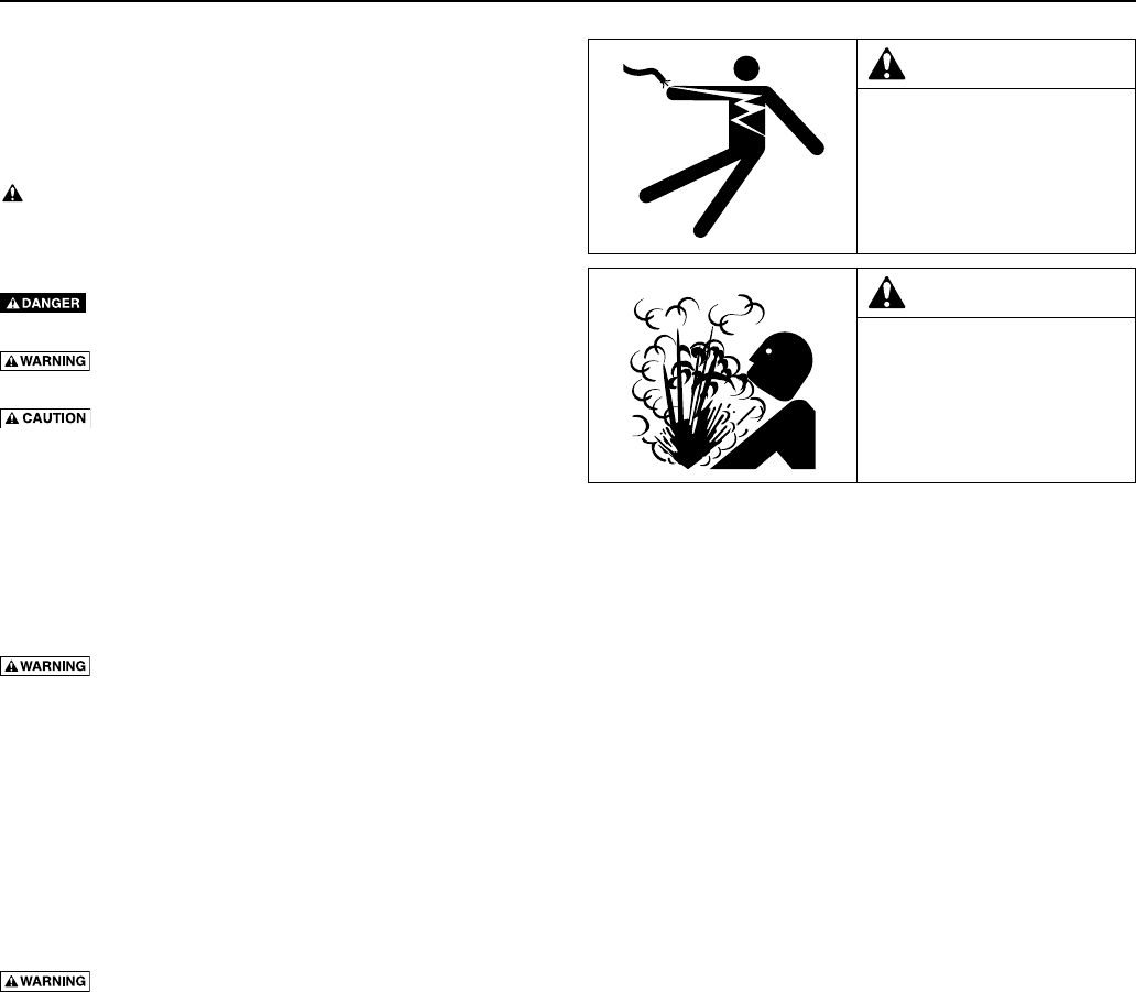
WARNING
Hazardous pressure!
Do not run pump against
closed discharge.
Release all pressure on
system before working on any
component.
WARNING
Hazardous voltage.
Can shock, burn, or cause
death.
Groundpumpbefore
connecting to power supply.

Warranty 3
Limited Warranty
BERKELEYwarrantstotheoriginalconsumerpurchaser(“Purchaser”or“You”)oftheproductslistedbelow,thattheywillbefree
from defects in material and workmanship for the Warranty Period shown below.
Product Warranty Period
Water Systems:
Water Systems Products — jet pumps, small centrifugal pumps, submersible pumps and
related accessories
whichever occurs first:
12 months from date of original installation, or
18 months from date of manufacture
Pro-Source™ Composite Tanks 5 years from date of original installation
Pro-Source™ Steel Pressure Tanks 5 years from date of original installation
Pro-Source™ Epoxy-Lined Tanks 3 years from date of original installation
Sump/Sewage/Effluent Products 12 months from date of original installation, or
18 months from date of manufacture
Agricultural/Commercial:
Centrifugals – close-coupled motor drive, frame mount, SAE mount, engine drive, VMS,
SSCX, SSHM, solids handling, submersible solids handling
12 months from date of original installation, or
24 months from date of manufacture
SubmersibleTurbines,6”diameterandlarger 12 months from date of original installation, or
24 months from date of manufacture
Our limited warranty will not apply to any product that, in our sole judgement, has been subject to negligence, misapplication,
improper installation, or improper maintenance. Without limiting the foregoing, operating a three phase motor with single phase
power through a phase converter will void the warranty. Note also that three phase motors must be protected by three-leg,
ambient compensated, extra-quick trip overload relays of the recommended size or the warranty is void.
Your only remedy, and BERKELEY’s only duty, is that BERKELEY repair or replace defective products (at BERKELEY’s choice). You
must pay all labor and shipping charges associated with this warranty and must request warranty service through the installing
dealer as soon as a problem is discovered. No request for service will be accepted if received after the Warranty Period has
expired. This warranty is not transferable.
BERKELEYSHALLNOTBELIABLEFORANYCONSEQUENTIAL,INCIDENTAL,ORCONTINGENTDAMAGESWHATSOEVER.
THEFOREGOINGLIMITEDWARRANTIESAREEXCLUSIVEANDINLIEUOFALLOTHEREXPRESSANDIMPLIED
WARRANTIES,INCLUDINGBUTNOTLIMITEDTOIMPLIEDWARRANTIESOFMERCHANTABILITYANDFITNESSFOR
APARTICULARPURPOSE.THEFOREGOINGLIMITEDWARRANTIESSHALLNOTEXTENDBEYONDTHEDURATION
PROVIDED HEREIN.
Some states do not allow the exclusion or limitation of incidental or consequential damages or limitations on the duration of an
implied warranty, so the above limitations or exclusions may not apply to You. This warranty gives You specific legal rights and
You may also have other rights which vary from state to state.
This Limited Warranty is effective June 1, 2011 and replaces all undated warranties and warranties dated before June 1, 2011.
In the U.S.: BERKELEY, 293 Wright St., Delavan, WI 53115
In Canada: 269 Trillium Dr., Kitchener, Ontario N2G 4W5
Installation 4
Before you install your pump
NOTICE: Well must not be more than 20’ depth to water.
1. Long runs and many fittings increase friction and reduce flow. Locate
pump as close to well as possible: use as few elbows and fittings
aspossible.
2. Be sure well is clear of sand. Sand will plug the pump and void
thewarranty.
3. Protect pump and all piping from freezing. Freezing will split pipe,
damage pump and void the warranty. Check locally for frost protection
requirements(usuallypipemustbe12”belowfrostlineandpumpmust
be insulated).
4. Be sure all pipes and foot valve are clean and in good shape.
5. No air pockets in suction pipe.
6. No leaks in suction pipe. Use PTFE pipe thread sealant tape to seal
pipejoints.
7. Unions installed near pump and well will aid in servicing. Leave room
to use wrenches.
8 Risk of explosion. Pump body may explode if used as a
booster pump. DO NOT use in a booster appli cation.
NOTICE: Use the installation method which matches your well type.
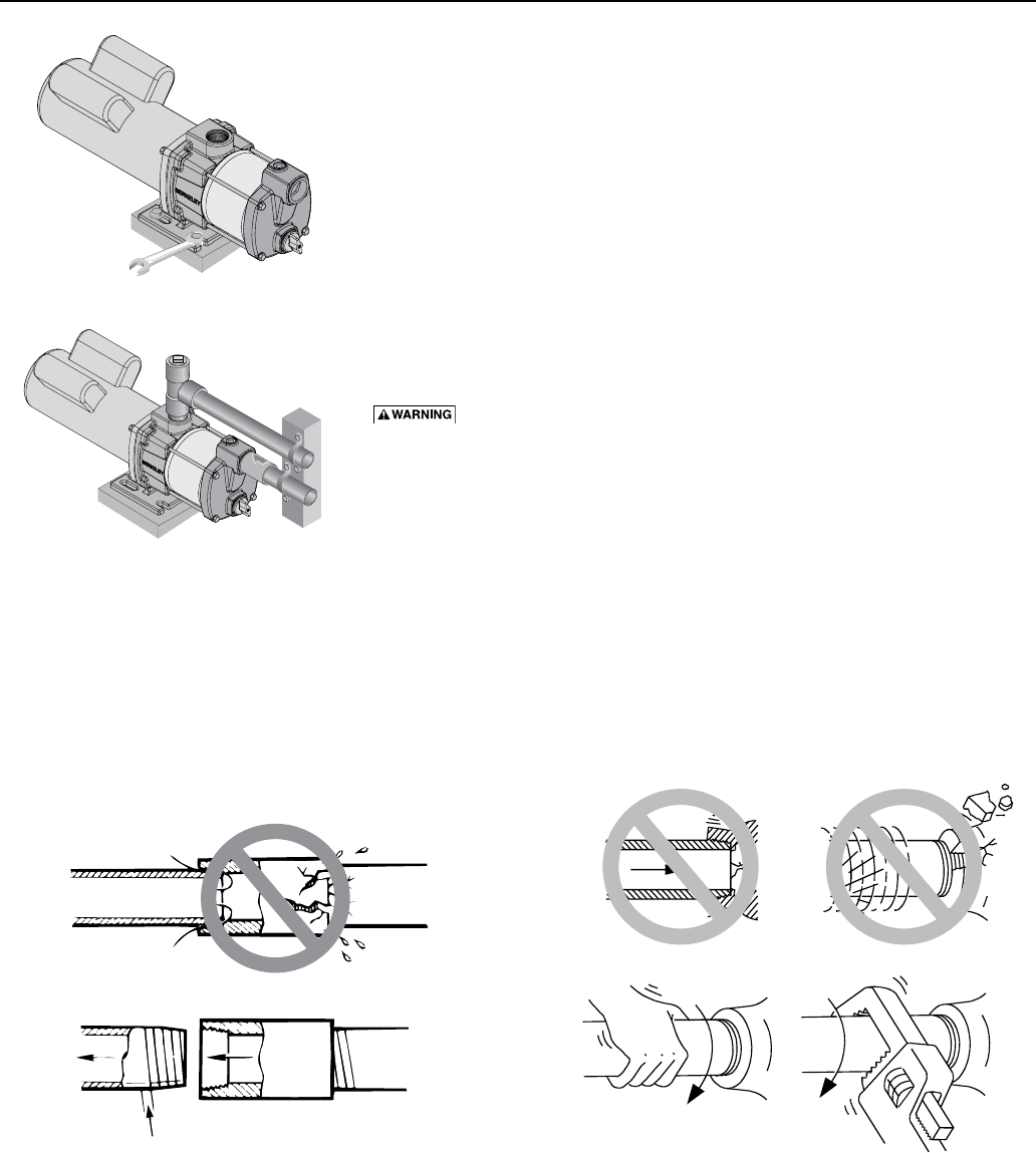
9. Install a check valve in the pump suction port. Be sure that the flow
arrow points toward the pump. Failure to install a check valve on the
inlet side of the pump may allow the pump body to drain between
pump cycles, causing dry running, seal or internal failure, and voiding
the warranty.
Pump
Body
e l
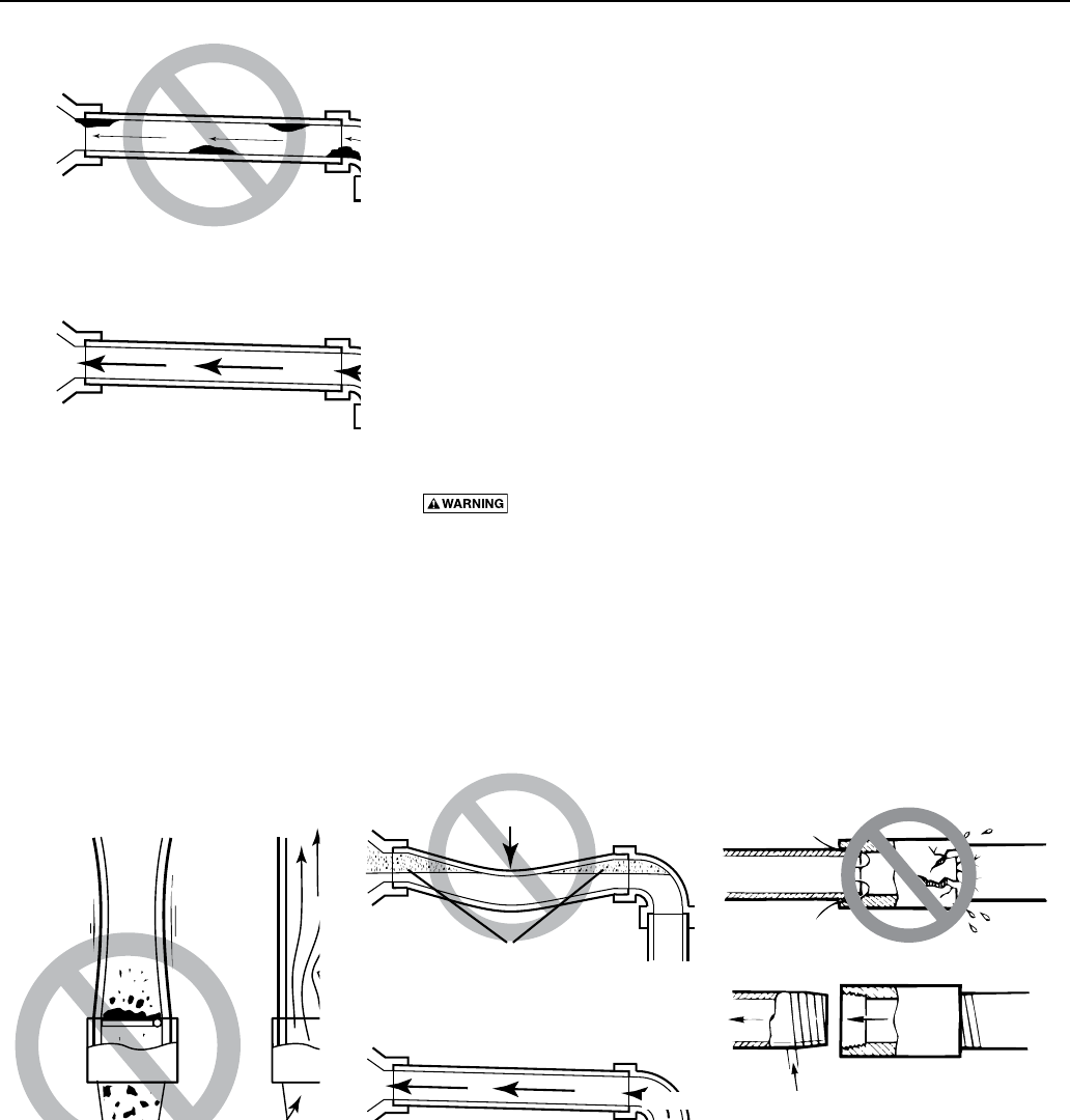
Dirt and Scale Plug Pump and Pipes
Use New Pipe for Best Results.
Clean Flow!
Figure 1 – No Dirt or Scale in Suction
Pipe
Figure 2 – Foot Valve Must Work
Freely
Figure 3 – No Air Pockets in Suction
Pipe
No Sags
Sags Allow Air Pockets
If Air Pockets Form, Water Won’t Flow.
Keep Pipe Straight and Angled up to Pump.
No air leaks In
Suction pipe.
If air flows
water won’t
Use PTFE tape.
Use PTFE pipe thread sealant tape or pipe joint
compound approved for use on PVC.
Figure 4 – Suction Pipe Must Not Leak
Installation 5
Cased Well Installation
1. Inspect foot valve to be sure it works freely. Inspect strainer to be sure it
is clean.
2. Connect foot valve and strainer to the first length of suction pipe and
lower pipe into well. Add sections of pipe as needed, using PTFE tape
on male threads. Be sure that all suction pipe is leakproof or pump
will lose prime and fail to pump. Install foot valve 10 to 20 feet below
the lowest level to which water will drop while pump is operating
(pumping water level). Your well driller can furnish this in formation.
3. To prevent sand and sediment from entering the pumping system, the
foot valve/strainer should be at least 5 feet above the bottom of the well.
4. When the proper depth is reached, install a sanitary well seal over the
pipe and in the well casing. Tighten the bolts to seal the casing.
5. When using a foot valve, a priming tee and plug as shown in Figure 5
are recommended.
Dug Well Installation
Same as cased well installation.
Driven Point Installation
1. Connect the suction pipe to the drive point as illustrated in Figure6.
Keep horizontal pipe run as short as possible. Use PTFE pipe thread
sealant tape on male pipe threads. Multiple well points may be
necessary to provide sufficient water to pump.
2. Install a check valve in horizontal pipe. Flow arrow on check valve
must point toward pump.
Horizontal Piping From Well To Pump
1. Never install a suction pipe that is smaller than the suction port of
thepump.
2. To aid priming on well point installations, install a line check valve as
shown in Figure 6. Be sure check valve flow arrow points toward pump.
Discharge Pipe Sizes
1. If increasing discharge pipe size, install reducer in pump discharge port.
Do not increase pipe size by stages.
2. When the pump is set away from the points of water use, the discharge
pipe size should be increased to reduce pressure losses caused
byfriction.
• Upto100’run:Samesizeaspumpdischargeport.
• 100’to300’run:Increaseonepipesize.
• 300’to600’run:Increasetwopipesizes.
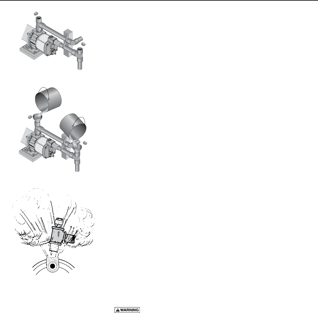
Sprinkling Application
This pump is de signed to deliver plenty of water at full sprinkler pres sure. It can
pump from a pond, cistern or well points.
Pump discharge can be divided to supply two (2) or more sprinkler systems.
A suggested multiple dis charge to service is shown in Figure 7.
Do not use in a pressure tank or booster pump application.
Pump Installation
Make sure that all pipe joints in the suction pipe are air tight as well as
water tight. If the suction pipe can suck air, the pump will not be able to
pull water from the well.
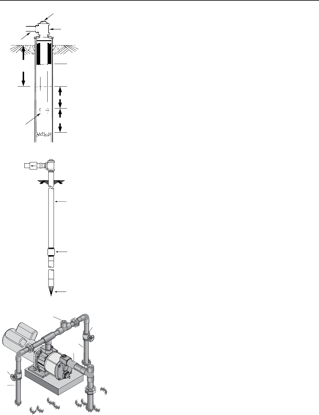
Figure 5 – Cased/Dug Well Installation
Suction
pipe
Foot
Valve
Priming plug
Priming tee
Standing water
level (pump off)
Drawdown water
level (pump on)
10-20' (3-6 m)
20' (6 m) max.
At least 5 feet (1.5 m)
2
Figure 6 – Driven Point Installation
Check valve
Steel drive pipe
Drive coupling
Driven point
99
Figure 7 – Multiple Discharge
Gate
Valve
Gate
Valve
To
Service
To
Service
Priming
Plug
Check
Valve
Installation 6
1 Bolt pump to solid, level foundation.
2. Support all piping connected to the pump.
3. Wrap 1-1/2 to two layers of PTFE tape clockwise (as you face end of
pipe) on all male threads being attached to pump.
4. Tighten joints hand tight plus 1-1/2 turns. Do not overtighten.
NOTICE : Install pump as close to well head as poss ible. Long piping runs
and many fittings create friction and reduce flow.
NOTICE: For long horizontal pipe runs, install a priming tee between check
valve and well head as shown in Figure 6. For driven point installations,
install a check valve as shown in Figure 6. Be sure check valve flow arrow
points toward pump.
Use schedule 80 or iron pipe. See Well Pipe In stalla tion for more
information.
Wiring
Hazardous voltage. Follow these rules to avoid potential harm:
• Groundmotorbeforeconnectingtoelectricalpowersupply.Failureto
ground motor can cause severe or fatal electrical shock hazard.
• Donotgroundtoagassupplyline.
• Toavoiddangerousorfatalelectricalshock,turnOFFpowertomotor
before working on electrical connections.
• Supplyvoltagemustbewithin±10%ofnameplatevoltage.Incorrect
voltage can cause fire or damage motor and voids warranty. If in doubt
consult a licensed electrician.
• UsewiresizespecifiedinWiring Chart. If possible, connect pump to a
separate branch circuit with no other appliances on it.
• Wiremotorasshown(Figure12B).Ifmotornameplatediagramdoes
not match either Figure 12A or 12B, follow nameplate diagram.
Figure 8 – Bolt Pump Down
Figure 9 – Independently Support All
Piping Attached to Pump
Figure 10 – Use PTFE pipe thread sealant tape on pipe
joints and connections to pump.
No air leaks In
Suction pipe.
If air flows
water won’t
Use PTFE tape.
Use PTFE pipe thread sealant tape or pipe joint
compound approved for use on PVC.
Figure 11 – Don’t overtighten.
Don’t Hit
Thread Stops
Don’t
Overtighten
From
Well
Pump
Body
Hand Tight Plus 1-1/2 Tu rns With Wrench.
Electrical 7
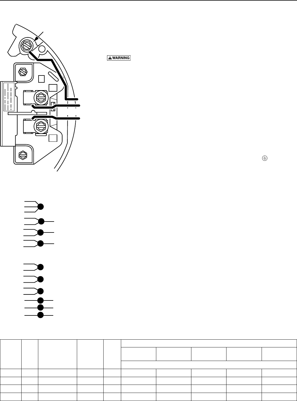
Connection Diagram for Single-Phase Motors
Your motor’s terminal board (under the motor end cover) should match the
diagram in Figure 12A or 12B.
For single-phase motors, follow Figure 12A. For 3-phase motors, follow
Figure 12B. If motor does not match this picture, follow the connection
diagram on the motor nameplate or in the motor connection box.
Hazardous voltage. Can shock, burn, or cause death. Disconnect
powertomotorbeforeworkingonpumpormotor.Groundmotorbefore
con necting to power supply.
1. Install, ground, wire and maintain this pump in accordance with
electrical code requirements. Consult your local building inspector for
information about codes.
2. Provide a correctly fused disconnect switch for protection while
working on motor. Consult local or national electrical codes for
switchrequirements.
3. Disconnect power before servicing motor or pump. If the disconnect
switch is out of sight of pump, lock it open and tag it to prevent
unexpected power appli cation.
4. Groundthepumppermanentlyusingawireofthesamesizeasthat
specified in wiring chart (below). Make ground connection to green
groundingterminalundermotorcanopymarkedGRD.or .
5. Connect ground wire to a grounded lead in the service panel or to a
metal underground water pipe or well casing at least 10 feet long. Do
not connect to plastic pipe or insulated fittings.
6. Protect current carrying and grounding conductors from cuts, grease,
heat, oil, and chemicals.
7. Connect current carrying conductors to terminals L1 and L2 under
motor canopy (single phase) or in motor connection box (3-phase).
When replacing motor, check wiring diagram on motor nameplate
against Figures 12A and 12B. If the motor wiring diagram does not
match one of the diagrams in Figures 12A and 12B, follow the dia gram
on the motor.
8. Motor has automatic internal thermal overload protection. If motor has
stopped for unknown reasons, thermal overload may restart it unex-
pectedly, which could cause injury or property damage. Disconnect
power before servicing motor.
9. If this procedure or the wiring diagram is con fusing, consult a
licensedelectrician.
A
L2
L1
230 Volts
Green
Ground
Screw
Figure 12A – 230V Single Phase
Wiring Diagram
Wiring Chart – Recommended Wire and Fuse Sizes
Model Motor
HP Volts/Hz/Phase Service
Factor Amp
Branch
Fuse*
Rating
Amp
Distance In Feet(Meters) From Motor To Supply
0 - 100
(0 - 30)
101 - 200
(31 - 61)
201 - 300
(62 - 91)
301 - 400
(92 - 122)
401 - 500
(123 - 152)
AWG Wire Size (mm²)
B82456 2 230/60/1 13.3 20 12 (3) 12 (3) 10 (5.5) 10 (5.5) 8 (8.4)
B82639 2 208-230/460/60/3 10.2/5.1 15/15 14 (2)/14 (2) 14 (2)/14 (2) 12 (3)/14 (2) 10 (5.5)/14 (2) 10 (5.5)/14 (2)
B86073 2 230/60/1 9.8 20 14 (2) 14 (2) 12 (3) 10 (5.5) 10 (5.5)
B86074 2 208-230/460/60/3 9.2/4.6 15/15 14 (2)/14 (2) 14 (2)/14 (2) 12 (3)/14 (2) 10 (5.5)/14 (2) 10 (5.5)/12 (3)
* Dual element time delay fuse
3-Phase Low Voltage
3-Phase High Voltage
4-Brown
5-Orange
6-Black
1-Red
7-Purple
2-White
8-Gray
3-Blue
9-Pink
4-Brown
7-Purple
5-Orange
8-Gray
6-Black
9-Pink
1-Red
2-White
3-Blue
LINE 1
LINE 2
LINE 3
LINE 1
LINE 2
LINE 3
To reverse
rotation,
interchange
any two line
leads.
Figure 12B – 3-Phase Wiring Diagram
Operation 8
Priming The Pump
NOTICE: The term ‘priming’ refers to the process of pumping all the air
out of the system, filling the pump and suction piping with water, and
beginning to move water through the pump and out into the system. A ‘self-
priming’ pump generally will repeat this process without attention once
the pump and system are full of water. If the water drains out of the pump
(back into the well, for example), then the whole priming process must be
repeated before operating the pump again.
To make sure that the pump will ‘retain its prime’ (that is, that the pump
and its piping will stay full of water), BE SURE to install a check valve in the
pump inlet port with the flow arrow pointing towards the pump. The check
valve will prevent water from siphoning out of the pump body and back
down into the well, which will keep the pump full and allow it to restart on
its own.
DO NOT remove the recirculation valve cover (there are spring-loaded
parts inside the recirculation valve – see Figure 16) when priming or
draining the pump. The drain is a hex-head pipe plug underneath the pump
body. To drain the pump, remove the hex plug (Ref. No. 17, Repair Parts
diagram). Do not disturb the recirculation valve (Ref. No. 19).
• Ifthepumporthesuctionpipehavebeendrainedforanyreason,
BE SURE to reprime the pump before starting it.
NOTICE: NEVER run the pump dry. Running the pump with out water in it
will damage the seals, can melt the impellers and diffusers, and voids the
warranty. To prevent damage, fill the pump with water before starting.
1. Remove priming plug (Figure 13).
2. Make sure suction and discharge valves and any hoses on discharge
side of pump are open.
3. Fill pump and suction pipe with water.
4. Replaceprimingplug,usingPTFEtapeonthread;tightenplug.
NOTICE: If a priming tee and plug have been provided for a long
horizontal run, be sure to fill suction pipe through this tee and replace
plug. (Don’t forget to PTFE tape the plug.)
5. Start pump: water should be produced in 5 minutes or less, the
time depending on depth to water (not more than 20’) and length of
horizontal run (10’ of horizontal suction pipe = 1’ of vertical lift due to
friction losses in the pipe).
If no water is produced within 5 minutes, stop pump, release all
pressure, remove priming plug, refill and try again.
Hazardous pressure and risk of ex plo sion and scalding. If pump
is run con ti nu ously at no flow (that is, with discharge shut off or without
priming), water may boil in pump and piping system. Under steam pressure,
pipes may rupture, blow off of fittings or blow out of pump ports and scald
anyone near.
To prevent explosion, do the following:
A. Be sure discharge (valve, pistol grip hose nozzle, etc.) is open whenever
pump is running.
B. If pump fails to produce water when attempting to prime, release
all pressure, drain pump and refill with cold water after every
twoattempts.
C. When priming, monitor pump and piping tempera ture. If pump or
piping begin to feel warm to the touch, shut off pump and allow system
to cool off. Release all pressure in system and refill pump and piping
with cold water.
Figure 13 – Remove Priming Plugs
Figure 14 – Fill Pump Before Starting
Figure 15 – Do Not Run Pump with
Discharge Shut-off.
3
Maintenance 9
Maintenance
If motor is replaced, replace the shaft seal and O-Rings. Keep a seal and
O-Rings on hand for future use.
Be sure to prime pump before starting.
NOTICE: The mechanical shaft seal in the pump is water lubricated and
self-adjusting.
NOTICE: Drain pump (see Figure 16) when disconnecting from service or
when it might freeze. You can fill the pump with RV anti-freeze (propylene
glycol) to prevent it from freezing. DO NOT remove the Recirculation Valve
to drain the pump (Figure 16). Remove the hex head plug on the bottom of
the Pump Suction Body to drain the pump.
Pump Disassembly
See Repair Parts for Ref. No. references.
NOTICE: Do not disturb the recirculation valve (see Figure 16). It is NOT a
drain plug!
1. Shut off power to the pump before working on it.
2. Close all suction and discharge valves to isolate the pump before
proceeding further.
3. Remove the hex head drain plug (Ref. No. 17) from the suction body
and drain the pump.
4. Disconnect the suction line.
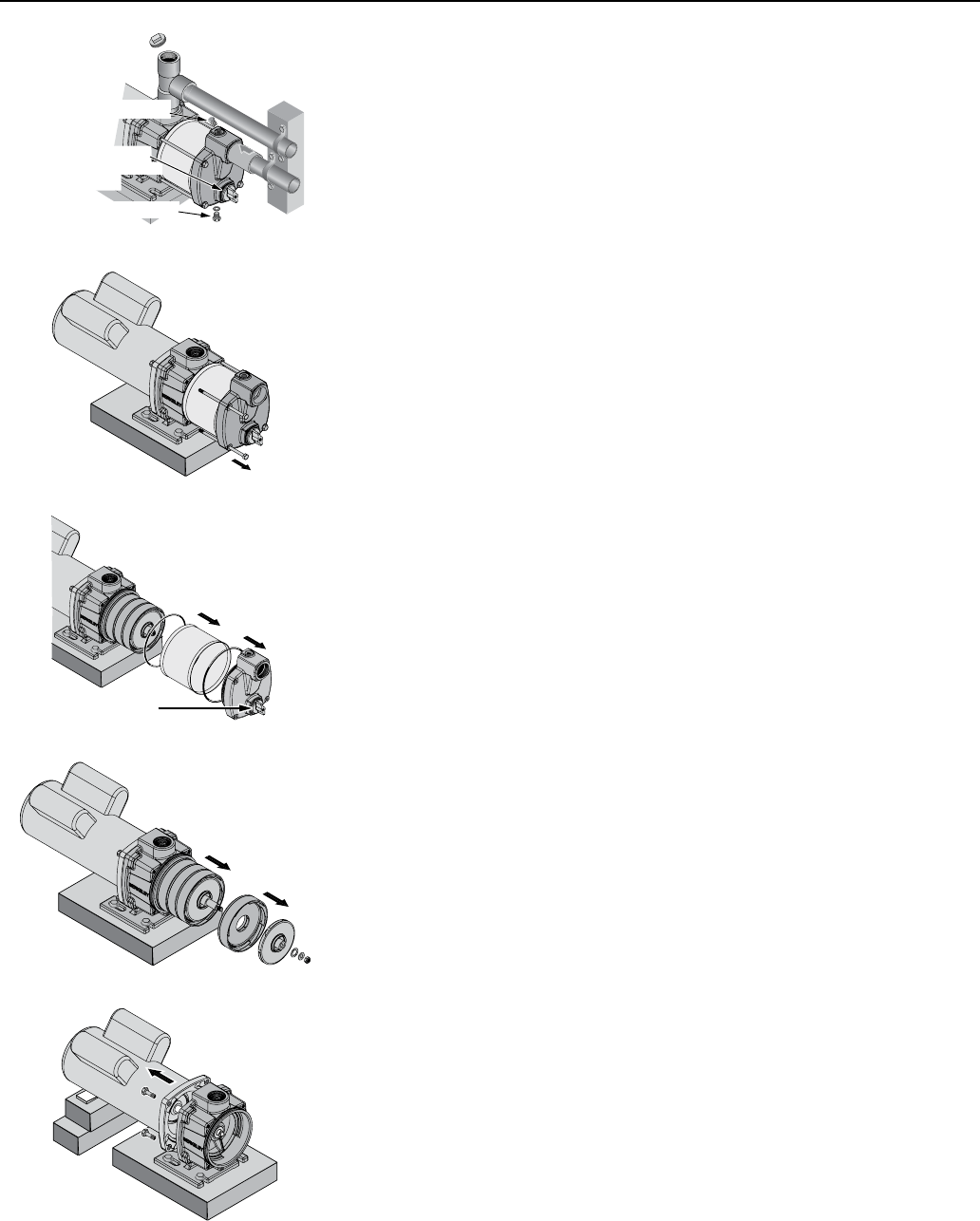
5. Remove four capscrews (Ref. No. 18) from the pump (see Figure 17).
6. Pull the pump suction body forward (see Figure 18). Remove the sleeve
(Ref. No. 9) by pulling it straight forward. Be careful not to damage the
O-rings on the bracket and suction body.
7. Removethemotorcanopy,holdthemotorshaftwitha7/16”openend
wrench, and remove the nut and two washers (Ref. Nos. 14, 13, 12)
from the end of the shaft. See Figure 19.
8. Slide the impellers and diffusers (Ref. Nos. 11, 10) off of the shaft
(Figure 19).
9. Slide the spacer (Ref. No. 7) off of the shaft, then pull the rotating half
of the seal (Ref. No. 6) forward on the shaft and remove it.
10. Block up the motor (so that the shaft will not take the weight of the
motor when you loosen the capscrews holding the motor to the
bracket), remove four capscrews (Ref. No. 2), and slide the motor and
shaft back out of the bracket (see Figure 20).
NOTICE: To avoid springing the shaft, be sure that the shaft does not
take the weight of the motor as you remove it.
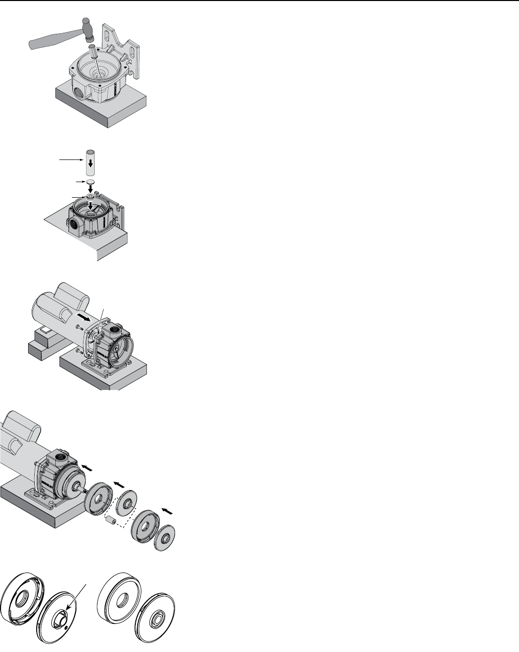
Figure 19
Figure 20
Figure 17
Recirculation Valve
Do not disturb!
Figure 18
Drain Plug
Recirculation Valve:
Do not disturb when
draining pump!
Vent Plug
Figure 16
Maintenance 10
Seal Removal
1. Followtheinstructionsunder“PumpDisassembly”,above.
2. Remove the discharge pipe from the bracket (Ref. No. 4).
3. Remove the hold down bolts from the bracket.
4. Turn the bracket motor side up on the bench and use a screwdriver to
carefully tap the stationary seal half out of the bracket (see Figure 21).
5. Clean the seal seat cavity in the bracket.
Seal Installation
1. Turn the bracket pump side up on the bench. You will need to block it
up to do this (See Figure 22).
2. Clean the seal cavity in the bracket.
3. Wet the outer edge of the rubber cup on the ceramic seat with liquid
soap. Be sparing!
4. Put a clean cardboard washer on the seal face. With thumb pressure,
press the ceramic seal half firmly and squarely into the seal cavity.
The polished face of the ceramic seat is up. If the seal will not seat
correctly, remove it, placing the seal face up on the bench. Reclean the
cavity. The seal should now seat correctly.
5. If the seal does not seat correctly after recleaning the cavity, place a
clean cardboard washer over the polished seal face and carefully press
itintoplaceusingapieceofstandard3/4”pipeasapress.
NOTICE: Be sure you do not scratch the seal face.
6. Dispose of the cardboard washer and recheck the seal face to be sure it
is free of dirt, foreign particles, scratches and grease.
7. Inspect the shaft to be sure it is free of nicks and scratches.
Pump Reassembly
1. Bolt the bracket down to the foundation (see Figure 23).
2. Slide the motor shaft through the seal and bolt up the motor (see
Figure23). Make sure that the slinger is on the shaft between the
bracket and the motor flange. Make sure that you don’t chip the seal
face with the shaft shoulders and that the shaft does not take the weight
of the motor at any time.
2. CAREFULLY slide the rotating seal half onto the shaft, seal face first.
Make sure that you don’t chip the seal face on the shaft shoulders.
3. Follow the seal half with the spacer (Ref. No. 7). Slide the washer up
against the seal.
4. Slide a diffuser onto the shaft (open face out) until it seats on the
bracket (see Figure 24). Follow the diffuser with an impeller on a four-
stage pump or with the stainless steel spacer if a three-stage pump.
Engage the molded impeller key in the slot in the shaft. Don’t force it!
Be sure that the impeller eye, with metal ring, faces out (forward - see
Figure 25).
5. Repeat step 4 with the remaining impellers and diffusers.
6. Reinstall the toothed washer, the flat washer, and the impeller nut (in
that order – Ref. Nos. 12,13,14) onto the motor shaft (see Figure 26).
Hold the shaft and tighten the impeller nut to 10 ft.-lbs. torque.
7. CheckthesleeveO-Rings;iftheyshowanydamageorwear,replace
them. Reinstall the sleeve O-Rings (Ref. No. 8) on the bracket and the
suction body.
Figure 24
Pipe
Cardboard
Washer
Seal Half
Figure 22
Slinger
Figure 23
Figure 21
Figure 25
Correct orientation Incorrect orientation
Metal ring
Maintenance • Troubleshooting 11
Troubleshooting
Symptom Possible Cause(s) Corrective Action(s)
Motor will not run
Disconnect switch is off Be sure switch is on.
Fuse is blown or circuit breaker
tripped. Replace fuse or reset circuit breaker.
Starting switch is defective. DISCONNECTPOWER;Replacestartingswitch.
Wires at motor are loose,
disconnected, or wired incorrectly.
Refertoinstructionsonwiring.DISCONNECTPOWER;checkandtightenallwiring.
Risk of electrical shock. Capacitor voltage may be hazardous. To
discharge capacitor, hold insulated handle screwdriver BY THE HANDLE and short
capacitor terminals together. Do not touch metal screwdriver blade or capacitor
terminals. If in doubt, consult a qualified electrician.
Motor runs hot and overload kicks
off.
Motor is wired incorrectly. Refer to instructions on wiring.
Voltage is too low Check with power company. Install heavier wiring if wire size is too small (See
Electrical / Wiring Chart).
Motor runs but no water is delivered
in new installation:*
1. Improper priming 1. Re-prime according to instructions.
2. Air leaks 2. Check all connections on suction line, with soapy water or shaving cream.
3. Leaking foot valve or check
valve 3. Replace foot valve or check valve.
Pump has lost prime in installation
already in use:
1. Air leaks 1. Check all connections on suction line and shaft seal.
2. Water level below suction pipe
inlet
2. Lower suction line into water and re-prime. If receding water level in well exceeds
20’ (6.1M), a deep well pump is needed.
Foot valve or strainer is plugged Clean foot valvye or strainer.
Impeller is plugged Clean impeller.
Check valve or foot valve is stuck
shut Replace check valve or foot valve.
Pipes are frozen Thaw pipes. Bury pipes below frost line. Heat pit or pump house.
Foot valve and/or strainer are
buried in sand or mud.
Raise foot valve and/or strainer above bottom of water source. Clean foot valve and
strainer.
Water level is too low for shallow
well setup to deliver water. Pump will not lift water more than 20’ (6.1M).
Pump does not deliver water to full
capacity.
Water level in well is lower than
estimated.
A deep well jet will be needed if depth to water in your well is more than 20’
(6.1m).
Steel piping (if used) is corroded
or limed, causing excess friction. Replace with plastic pipe where possible, otherwise with new steel pipe.
Piping is too small in size Use larger piping.
Packed well point Backflush well point or sink new point.
*Stoppump;thencheckprime
before looking for other causes.
Unscrew priming plug and see if
water is in priming hole.
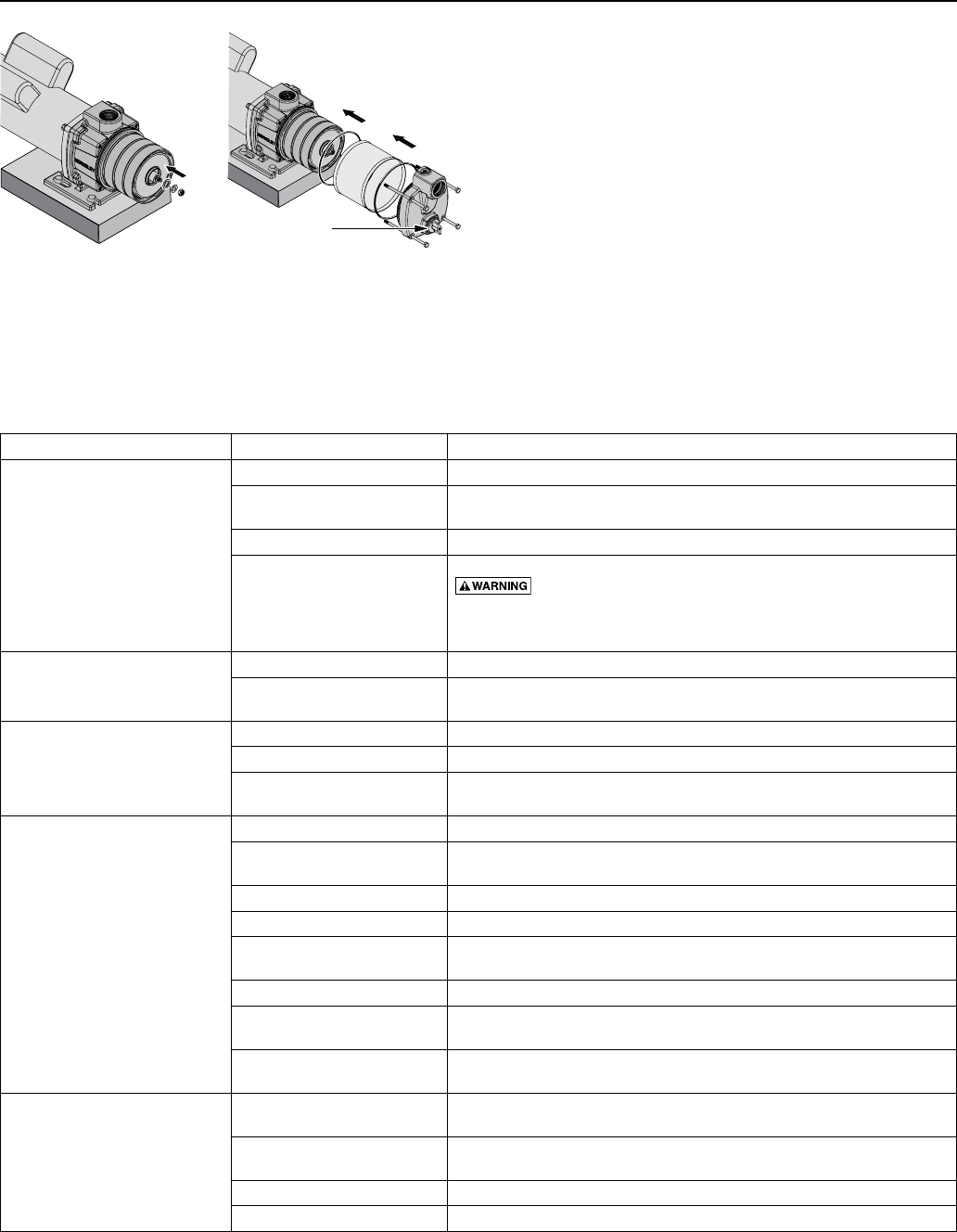
Recirculation Valve
Do not disturb!
Figure 27
Figure 26
8. Reinstall the sleeve on the bracket and the pump
suction body in the sleeve. Be sure that you do not
pinch or damage the O-Ring. See Figure27.
9. Install four capscrews (Ref. No. 18) through the
pump head and into the bracket. Tighten the
capscrews to 22ft.-lbs. torque.
10. Reinstall the drain plug and washer (Ref. Nos. 17
and 16) in the suction body.
NOTICE: Do not disturb the recirculation valve.
11. Reinstall the suction and discharge piping and open
all valves. Check for leaks.
12. Prime the pump according to the instructions on
Page 8.
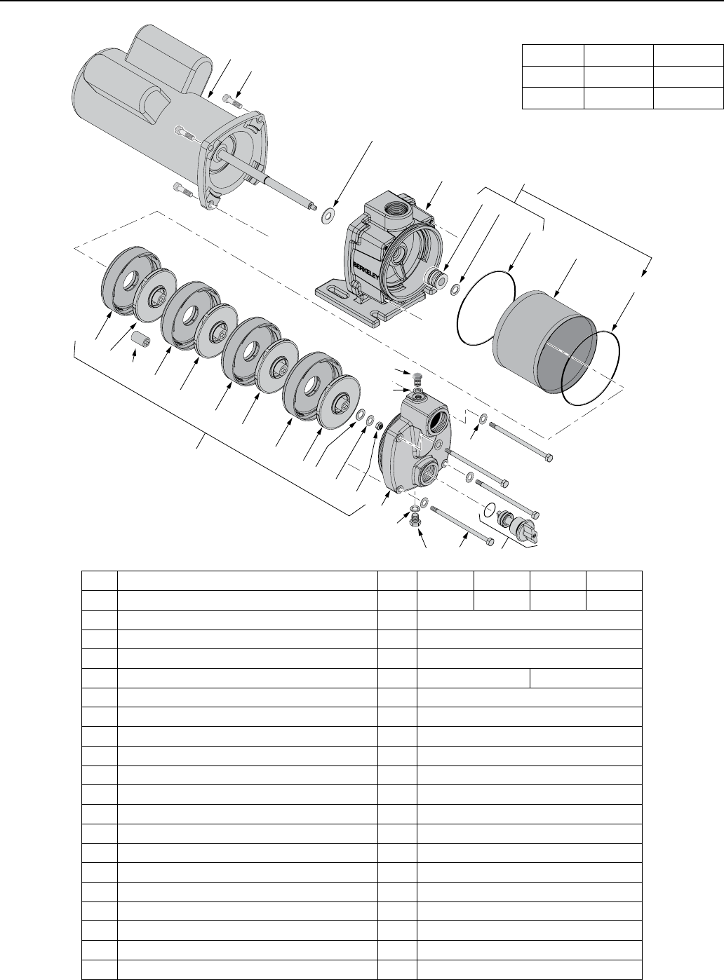
Repair Parts 12
Ref. Part Description Qty. B82456 B82639 B86073 B86074
1 Motor 1 B85740 B86076 B86075 B86077
2Socket Head Capscrew 4 U30-104ZP
3 Slinger 1 17351-0009
4 Bracket 1 M13784
5Impeller Repair Kit (Includes Ref. Nos. 6–8 and 10–14) 1 B85604 B86078
6 Shaft Seal 1 U9-469
7 Spacer 1 121P1710
8 O-Ring 2 111P2700
9 Sleeve 1 251A4310
10 Diffuser 4 101P6290
11 Impeller 3 or 4 101P6210
11A Spacer (3 Stg pump only) 1 M15780
12 Washer, Flat 1 121P1760
13 Washer, Toothed 5 M13975
14 Impeller Nut 1 U36-204SSW
15 Pump Body (Suction) 1 751S4800
16 Washer 2 121P0810
17 Pipe Plug 2 171P1180
18 Capscrew 4 121P1690
19 Recirculation Valve Complete (Includes O-Ring) 1 ZBR05820
12
3
10 1111A10
11
10
11
10
11 12
13
13 14
15
18
16
17 19
16
17
45
5
67
8
9
8
Exploded View
1 ø 3 ø
3 Stage B86073 B86077
4 Stage B82456 B82639
