536679 4 Generac 6438 Installation Drawing C User Manual
536680 4 Generac 6437 Installation Drawing 536680_4_Generac 6437 Installation Drawing
User Manual: Pump 536679 4 Generac 6438 Installation Drawing
Open the PDF directly: View PDF ![]() .
.
Page Count: 14
10
Section 3 7MXI7IPIGXMSRERH4VITEVEXMSR
MRQQ
1MRMQYQ(MWXERGI
MR
QQ
MR
QQ
MR
QQ
MRQQ MRQQ
)\MWXMRK;EPP
2SSTIVEFPI[MRHS[WSVSTIRMRKWMRXLI[EPPTIVQMXXIH
[MXLMRJXQJVSQER]TSMRXSJXLIKIRIVEXSV
8STSJ+IRIVEXSV
MRQQ
1MRMQYQ
MRQQ
6IGSQQIRHIH
1MRMQYQ*VSQ)RHW
MR
QQ
1MRMQYQ
+IRIVEXSV
'PIEVERGIJVSQSTIVEFPI
[MRHS[WHSSVWSVER]
STIRMRKWMRXLI[EPP
'PIEVERGIJVSQXLIIRHWERHJVSRXSJXLIKIRIVEXSV
QYWXFIMRQQ8LMW[SYPHMRGPYHIWLVYFW
XVIIWERHER]OMRHSJZIKIXEXMSRWLSVXIVXLERMR
QQMRLIMKLX:IKIXEXMSRXEPPIVXLERMR
QQMRLIMKLXQYWXLEZIEGPIEVERGISJMR
QQ'PIEVERGIEXXLIXSTWLSYPHFIE
QMRMQYQSJMRQQJVSQER]WXVYGXYVI
SZIVLERKSVTVSNIGXMSRWJVSQXLI[EPP8LIKIRIVEXSV
WLSYPHRSXFITPEGIHYRHIVEHIGOSVSXLIVWXVYGXYVI
XLEXMWGPSWIHMRERH[SYPHPMQMXSVGSRWXVEMREMVJPS[
8LIWIKYMHIPMRIWEVIFEWIHYTSRJMVI
XIWXMRKSJXLIKIRIVEXSVIRGPSWYVIERH
XLIQERYJEGXYVIVvWVIUYMVIQIRXJSVEMV
JPS[JSVTVSTIVSTIVEXMSR0SGEPGSHIW
QE]FIHMJJIVIRXERHQSVIVIWXVMGXMZI
XLER[LEXMWHIWGVMFIHLIVI
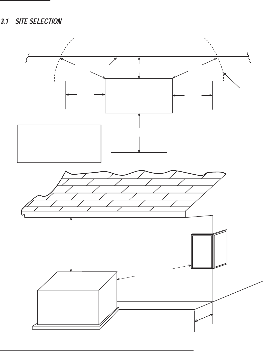
*MKYVIz-RWXEPPEXMSR+YMHIPMRIW

11
Install the generator set, in its protective enclosure, SYXHSSVW, where adequate cooling and ventilating air is always available (Figure 1.9). Consider
these factors:
• The installation of the generator QYWXGSQTP]WXVMGXP][MXL2*4%2*4%2*4%ERH2*4%WXERHEVHW
• Install the unit where air inlet and outlet openings will not become obstructed by leaves, grass, snow, etc. If prevailing winds will cause blowing or
drifting, consider using a windbreak to protect the unit.
• Install the generator on high ground where water levels will not rise and endanger it. It should not operate in or be subjected to standing water.
• Allow suffi cient room on all sides of the generator for maintenance and servicing. This unit must be installed in accordance with current applicable
NFPA 37 and NFPA 70 standards, as well as any other federal, state and local codes for minimum distances from other structures. DO NOT install
under wooden decks or structures unless there is at least 5ft. (1.52m) of clearance above the generator, 3ft. (.91m) of clearance on sides and
front, and a minimum of 18in. (457mm) of clearance at the back of the unit.
• Install the unit where rain gutter down spouts, roof run-off, landscape irrigation, water sprinklers or sump pump discharge does not fl ood the unit or
spray the enclosure, including any air inlet or outlet openings.
• Install the unit where services will not be affected or obstructed, including concealed, underground or covered services such as electrical, fuel,
phone, air conditioning or irrigation. This could affect Warranty Coverage.
• Where strong prevailing winds blow from one direction, face the generator air inlet openings to the prevailing winds.
• Install the generator as close as possible to the fuel supply to reduce the length of piping. REMEMBER THAT LAWS OR CODES MAY
REGULATE THE DISTANCE AND LOCATION.
• Install the generator as close as possible to the transfer switch. REMEMBER THAT LAWS OR CODES MAY REGULATE THE DISTANCE AND
LOCATION.
• The generator must be installed on a level surface. The generator must be level within a .5in (13mm) all around.
• The generator is typically placed on pea gravel, crushed stone or a concrete pad. Check local codes to see what type is required. If a concrete
pad is required, all federal, state and local codes should be followed.
The National Fire Protection Association has a standard for the installation and use of stationary combustion engines. That standard is NFPA 37, its
requirements limit the spacing of an enclosed generator set from a structure or wall (Figure 1.10).
NFPA 37, Section 4.1.4, Engines Located Outdoors: Engines, and their weatherproof housings if provided, that are installed outdoors shall be
located at least 5ft. (1.52m) from openings in walls and at least 5ft. (1.52m) from structures having combustible walls. A minimum separation shall not
be required where either of the following conditions exist:
1. The adjacent wall of the structure has a fi re resistance rating of at least 1 hour.
2. The weatherproof enclosure is constructed of noncombustible materials and it has been demonstrated that a fi re within the enclosure will not
ignite combustible materials outside the enclosure.
Annex A — Explanatory Material
A4.1.4 (2) Means of demonstrating compliance are by means of full scale fi re test or by calculation procedures.
Because of the limited spaces that are frequently available for installation, it has become apparent that exception (2) would be benefi cial for many
residential and commercial installations. With that in mind, the manufacturer contracted with an independent testing laboratory to run full scale fi re
tests to assure that the enclosure will not ignite combustible materials outside the enclosure.
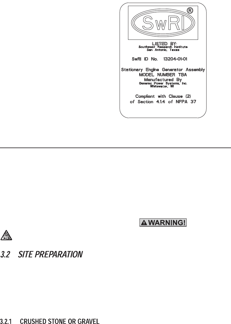
238)7SYXL[IWX6IWIEVGL-RWXMXYXIXIWMRKETTVSZIWMRQQMRWXEPPEXMSRQMRMQYQJVSQWXVYGXYVI7SYXL[IWX6IWIEVGLMWE
REXMSREPP]VIGSKRM^IHXLMVHTEVX]XIWXMRKERHPMWXMRKEKIRG]
The criteria was to determine the worst case fi re scenario within the generator and to determine the ignitability of items outside the engine enclosure
at various distances. The enclosure is constructed of non-combustible materials, and the results and conclusions from the independent testing lab
indicated that any fi re within the generator enclosure would not pose any ignition risk to nearby combustibles or structures, with or without fi re service
personnel response.
12
*MKYVI{7SYXL[IWX6IWIEVGL-RWXMXYXI(IGEPPSGEXIHMRWMHIXLIKIRIVEXSVRI\XXSXLIKIRIVEXSVvWHEXEHIGEP
LXXT[[[W[VMSVKSVKHJMVIPMWXPEFPMWXTVSHHMVIGXSVLXQ
&EWIHSRXLMWXIWXMRKERHXLIVIUYMVIQIRXWSJ2*4%7IGXLIKYMHIPMRIWJSVMRWXEPPEXMSRSJXLIKIRIVEXSVWPMWXIHEFSZIEVI
GLERKIHXSMRQQJVSQXLIFEGOWMHISJXLIKIRIVEXSVXSEWXEXMSREV][EPPSVFYMPHMRK For adequate maintenance and airfl ow
clearance, the area above the generator should be at least JX Q with a minimum of 3ft. (.91m) at the front and ends of the enclosure. This
would include trees, shrubs and vegetation shorter than 12in. (305mm) in height. Vegetation taller than 12in. (305mm) in height must have a
clearance of 60in. (1524mm). Vegetation not in compliance with these clearance parameters could obstruct air fl ow. In addition, exhaust fumes from
the generator could inhibit plant growth. See Figure 3.1 and the installation drawing within the owner’s manual for details.
Generator exhaust contains DEADLY carbon monoxide gas. This dangerous gas can cause unconsciousness or death. Do not place the unit near
windows, doors, fresh air intakes (furnaces, etc.) or any openings in the building or structure, including windows and doors of an attached garage.
-JXLIKIRIVEXSVMWRSXWIXXSXLI3**QSHIMXGERGVEROERHWXEVXEWWSSREWXLIFEXXIV]GEFPIWEVIGSRRIGXIH-JXLIYXMPMX]TS[IV
WYTTP]MWRSXXYVRIHSJJWTEVOMRKGERSGGYVEXXLIFEXXIV]TSWXWERHGEYWIERI\TPSWMSR
• Locate the mounting area as close as possible to the transfer switch and fuel supply.
• Leave adequate room around the area for service access (check local code), and place high enough to keep rising water from reaching the
generator.
• Choose an open space that will provide adequate and unobstructed airfl ow.
• Place the unit so air vents won’t become clogged with leaves, grass, snow or debris. Make sure exhaust fumes will not enter the building through
eaves, windows, ventilation fans or other air intakes (see the “Site Selection” section).
• Select the type of base, gravel or concrete, as desired or as required by local laws or codes. Verify your local requirements before selecting.
• Dig a rectangular area approximately 5in. (127mm) deep and about 6in. (152mm) longer and wider than the footprint of the generator. Cover with
polyurethane fi lm, if desired, and fi ll with pea gravel or crushed stone. Compact and level the stone. A concrete pad can be poured if desired or
required. The pad should be 4-5in. (102-127mm) thick and extend 6in. (152mm) beyond the outside of the generator in all directions.
238)-JEGSRGVIXITEHMWVIUYMVIHJSPPS[EPPETTPMGEFPI*IHIVEP7XEXISVPSGEPGSHIW
15
%
&
'
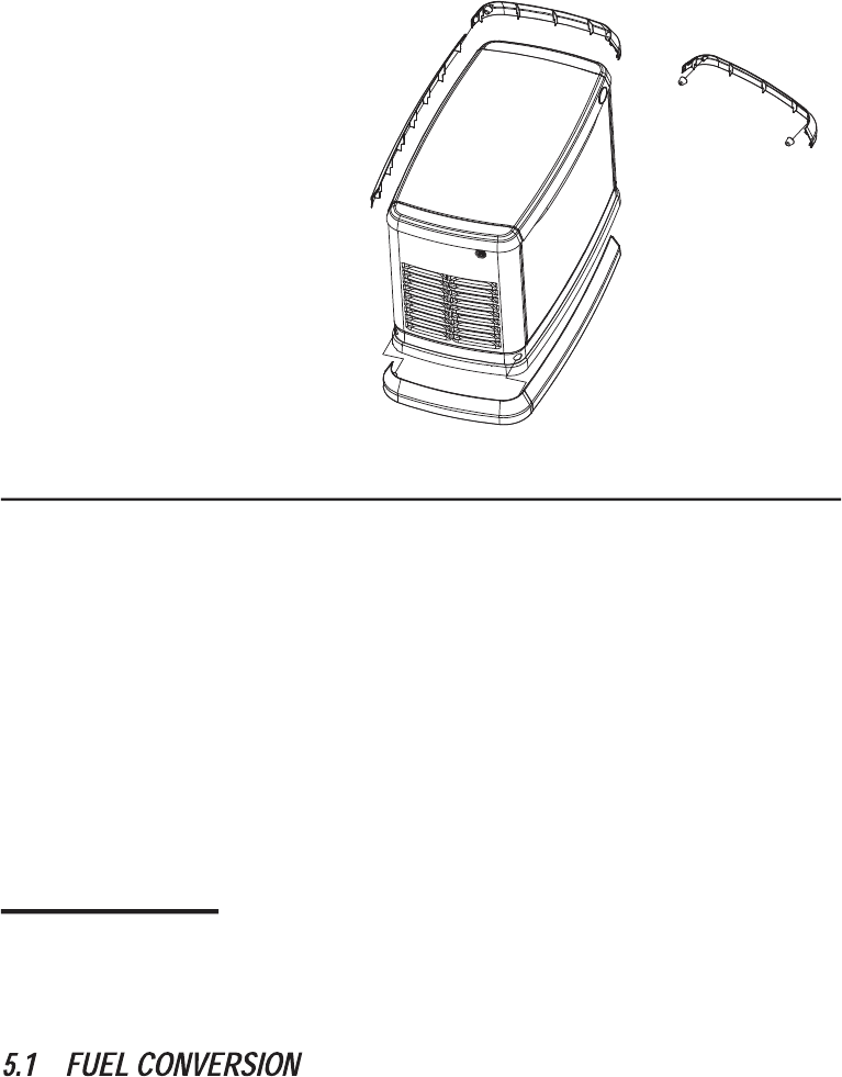
*MKYVI{*EWGME-RWXEPPEXMSR
%JXIVGSQTPIXMRK+)2)6%83640%')1)28TVSGIIHXS
7XIT
7)'8-32{*9)0'32:)67-32+%76)59-6)1)287
'322)'8-327
Section 5 Fuel Conversion / Gas Requirements /
Connections
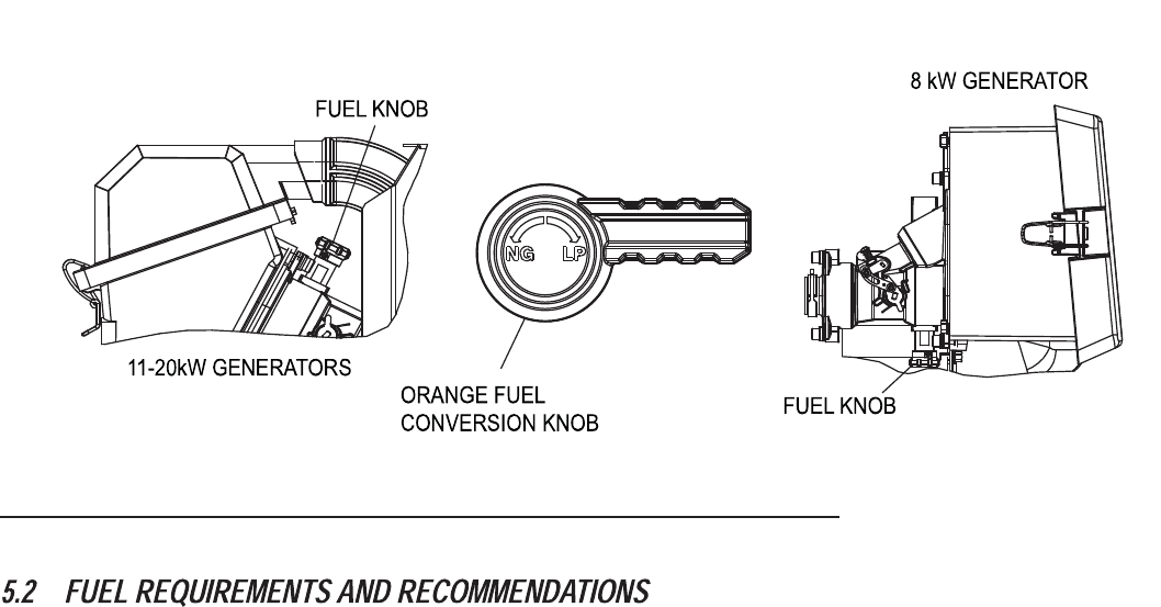
The generator was confi gured for natural gas operation at the factory. Switching over to LP Vapor is a simple procedure.
238)8LISVERKIJYIPGSRZIVWMSRORSFMWPSGEXIHSRXLIXSTSJXLIJYIPQM\IVSRXLI:X[MRIRKMRIERHYRHIVXLIJYIPQM\IVSRXLIWMRKPI
G]PMRHIVIRKMRI
Turn the valve towards the marked fuel source arrow until it stops. If needed, use pliers to break free in correct direction of arrow. Fuel knob will
rotate 180° and slide into the mixer body when converting to LP.
16
FUEL KNOB LOCATIONS SHOWN FROM GENERATOR AIR BOX SIDE VIEW
*MKYVI{*YIP'SRZIVWMSR/RSF0SGEXMSRJSV7MRKPIERH8[MR']PMRHIV+IRIVEXSVW
;MXL04KEWYWISRP]XLIZETSV[MXLHVE[EPW]WXIQThis type of system uses the vapors formed above the liquid fuel in the storage tank.
The engine has been fi tted with a fuel carburetion system that meets the specifi cations of the 1997 California Air Resources Board for tamper-proof
dual fuel systems. The unit will run on natural gas or LP gas, but it has been factory set to run on natural gas. Should the primary fuel need to be
changed to LP gas, the fuel system needs to be reconfi gured. See the Fuel Conversion section for instructions on converting the fuel system.
Recommended fuels should have a Btu content of at least 1,000 Btus per cubic foot (37.26 megajoules per cubic meter) for natural gas; or at least
2,500 Btus per cubic foot (93.15 megajoules per cubic meter) for LP gas. Ask the fuel supplier for the Btu content of the fuel.
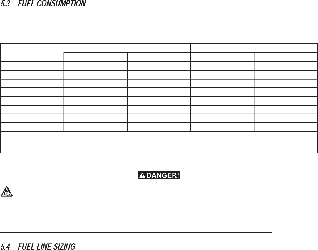
6IUYMVIHJYIPTVIWWYVIJSV REXYVEPKEWMWx[EXIVGSPYQRQQQIVGYV]6IUYMVIHJYIPTVIWWYVIJSVJSVPMUYMHTVSTERIZETSVMW
x[EXIVGSPYQRQQQIVGYV]8LITVMQEV]VIKYPEXSVJSVXLITVSTERIWYTTP]MW238-2'09()([MXLXLIKIRIVEXSV
238)%PPTMTIWM^MRKGSRWXVYGXMSRERHPE]SYXQYWXGSQTP][MXL2*4%JSVREXYVEPKEWETTPMGEXMSRWERH2*4%JSVPMUYMHTVSTERI
ETTPMGEXMSRW3RGIXLIKIRIVEXSVMWMRWXEPPIHZIVMJ]XLEXXLIJYIPTVIWWYVI2):)6HVSTWFIPS[MXvWVIUYMVIHJYIPTVIWWYVIVEXMRK*SVJYV
XLIVMRJSVQEXMSRVIKEVHMRK2*4%VIUYMVIQIRXWVIJIVXSXLIMV[IFWMXIEX[[[RJTESVK
Prior to installation of the generator, the installer should consult local fuel suppliers or the fi re marshal to check codes and regulations for proper
installation. Local codes will mandate correct routing of gaseous fuel line piping around gardens, shrubs and other landscaping to prevent any
damage.
Special considerations should be given when installing the unit where local conditions include fl ooding, tornados, hurricanes, earthquakes and
unstable ground for the fl exibility and strength of piping and their connections.
Use an approved pipe sealant or joint compound on all threaded fi ttings.
All installed gaseous fuel piping must be purged and leak tested prior to initial start-up in accordance with local codes, standards and regulations.
17
238)6IUYMVIHJYIPTVIWWYVIJSVREXYVEPKEWMWx[EXIVGSPYQRQQQIVGYV]8LIVIUYMVIHJYIPTVIWWYVIJSV04:ETSVMWx
[EXIVGSPYQRQQQIVGYV]
These are approximate values, use the appropriate spec sheet or owner’s manual for specifi c values.
Unit Nat. Gas LP Vapor
1/2 Load Full Load 1/2 Load Full Load
7 / 8 kW 78 / 2.21 121 / 3.43 0.87 / 3.29 1.42 / 5.37
10 / 11 kW 124 / 3.51 195 / 5.52 1.18 / 4.45 1.92 / 7.28
13 / 13 kW 157 / 4.45 255 / 7.22 1.64 / 6.2 2.95 / 11.15
14 / 14 kW 177 / 5.01 279 / 7.9 1.85 / 6.99 3.07 / 11.61
15 / 15 kW 185 / 5.24 296 / 8.38 1.83 / 6.91 2.86 / 10.82
16 / 16 kW 193 / 5.47 312 / 8.83 1.9 / 7.2 3.19 / 12.07
16 / 17 kW 193 / 5.47 312 / 8.83 1.99 / 7.53 3.57 / 13.53
18 / 20 kW 205 / 5.8 308 / 8.72 2.08 / 7.87 3.85 / 14.57
* Natural gas is in cubic feet per hour / cubic meters per hour.
** LP is in gallons per hour / liters per hour.
*** Values given are approximate.
:IVMJ]XLEXKEWQIXIVMWGETEFPISJTVSZMHMRKIRSYKLJYIP S[XSMRGPYHILSYWILSPHETTPMERGIWERHEPPSXLIVPSEHW
+EWISYWJYIPWWYGLEWREXYVEPKEWERHPMUYMHTVSTERI04KEWEVILMKLP]I\TPSWMZI)ZIRXLIWPMKLXIWXWTEVOGERMKRMXIWYGLJYIPW
ERHGEYWIERI\TPSWMSR2SPIEOEKISJJYIPMWTIVQMXXIH2EXYVEPKEW[LMGLMWPMKLXIVXLEREMVXIRHWXSGSPPIGXMRLMKLEVIEW04KEW
MWLIEZMIVXLEREMVERHXIRHWXSWIXXPIMRPS[EVIEW
238)%QMRMQYQSJSRIETTVSZIHJYPPJPS[QERYEPWLYXSJJZEPZIQYWXFIMRWXEPPIHMRXLIKEWISYWJYIPWYTTP]PMRI8LIZEPZIQYWXFI
IEWMP]EGGIWWMFPI0SGEPGSHIWHIXIVQMRIXLITVSTIVPSGEXMSR
238)8,)+%779440=%2(4-4)1978&)7->)(%803%(&891)+%.390)6%8-2+
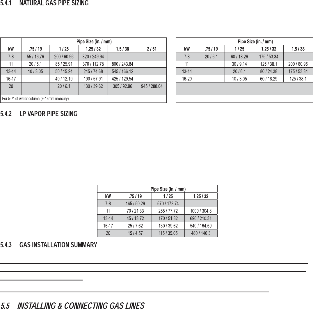
• First, determine what size pipe is required. Refer to NFPA 54 for NG or NFPA 58 for LP for further information.
• Always refer to the owner’s manual for the proper BTU / megajoule and required gas pressures. To calculate BTU or Megajoules:
– Natural Gas: BTU=Cubic feet / hour x 1000
Megajoules=Cubic meters / hour x 37.26
– Liquid Propane Vapor: BTU=Cubic feet / hour x 2500
Megajoules=Cubic meters / hour x 93.15
• Start by measuring the distance from the generator to the gas source. The generator should be plumbed directly from the source, not off the end
of an existing system.
• When measuring the pipe length, add 2.5ft. (.76m) for every angle or bend in the pipe and add that to the overall pipe distance.
18
To properly use this chart, fi nd the kW rating of the generator in the left column, and trace to the right. The number to the right is the maximum length
(measured in feet / meters) allowed for the pipe sizes on top. The pipe sizes are measured by inside diameter (ID) to include any fi ttings, valves
(must be full fl ow), elbows, tees or angles. Add 2.5ft. (.76m) per any bend, tee or angle in the pipe to the overall distance.
For pressures below 5" of water column (9mm mercury) down to 3.5” of water
column (7mm mercury)
To properly use this chart, fi nd the kW rating of the generator in the left column, and trace to the right. The number to the right is the maximum length
(measured in feet / meters) allowed for the pipe sizes on top. The pipe sizes are measured by inside diameter (ID) to include any fi ttings, valves
(must be full fl ow), elbows, tees or angles. Add 2.5ft. (.76m) per any bend, tee or angle in the pipe to the overall distance.
238)4MTIWM^IWEVIYWMRKEWIGSRHWXEKIVIKYPEXSV
238)8LIQMRMQYQ04XEROWM^IMWKEPPSRW0YRPIWWYRMXGEPGYPEXMSRWHMGXEXIYWISJEPEVKIVXERO:IVXMGEPXEROW[LMGL
EVIQIEWYVIHMRTSYRHWSVOMPSKVEQW[MPPRSXYWYEPP]QIIXXLIQMRMQYQXEROWM^IVIUYMVIQIRX%PFOKZIVXMGEPXEROWM^I
QMRMQYQMWVIUYMVIH
+%74-4)7->-2+-732)3*8,)1378'311320=1%()1-78%/)7%4634)60=7->)(+%74-4)-7'6-8-
'%0838,)4634)634)6%8-323*8,)+)2)6%8368,)+)2)6%836-20)87->),%723&)%6-2+32
8,)4634)6+%74-4)7->)
238)8,)+%779440=%2(4-4)1978&)7->)(%803%(&891)+%.390)6%8-2+
1. Both natural gas and LP Vapor are highly volatile substances, so strict adherence to all safety procedures, codes, standards and
regulations is essential.
Gas line connections should be made by a certified plumber familiar with local codes. Always use AGA-approved gas pipe and a quality
pipe sealant or joint compound.
Verify the capacity of the natural gas meter or the LP tank in regards to providing sufficient fuel for both the generator and other operating
appliances.
• Fuel Regulator installed per laws or regulator manufacturer’s specifi cations
• AGA approved gas pipe
• Flexible fuel line
– Do not bend!!!
– Do not attach directly to generator
– Check all connections for leaks
• Sediment trap near generator (if applicable or required by code)
• Full fl ow rated shut-off near generator per local jurisdiction or code
19
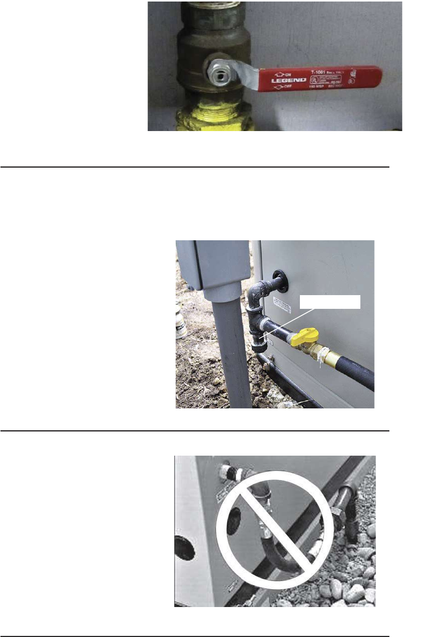
2. Most applications will require an external manual full flow shutoff valve on the fuel line.
*MKYVI{*YPP*PS[7LYXSJJ:EPZI
3. When connecting the gas line to the generator, use the provided section of UL Listed or AGA-approved flexible fuel line in accordance with
local regulations. The purpose of the flexible fuel line is to ensure that vibration from the generator does not cause a gas leak at one of the
connection points, so its important that the line be installed with as few bends as possible. Configure the sediment trap (if applicable or
required by code) as illustrated.
7)(-1)2886%4
*MKYVI{7IHMQIRX8VET
*MKYVI{-RGSVVIGX6SYXMRKSJ*PI\MFPI,SWI
20
4. Never bend the flexible fuel line to avoid using an elbow. Bending the flexible line decreases its ability to absorb vibrations and defeats its
purpose, as well as constricts the actual fuel flow. See Figure 5.5.
5. Check for leaks by spraying all connection points with a soap solution made of dishwashing soap and water. You should not see the solution be
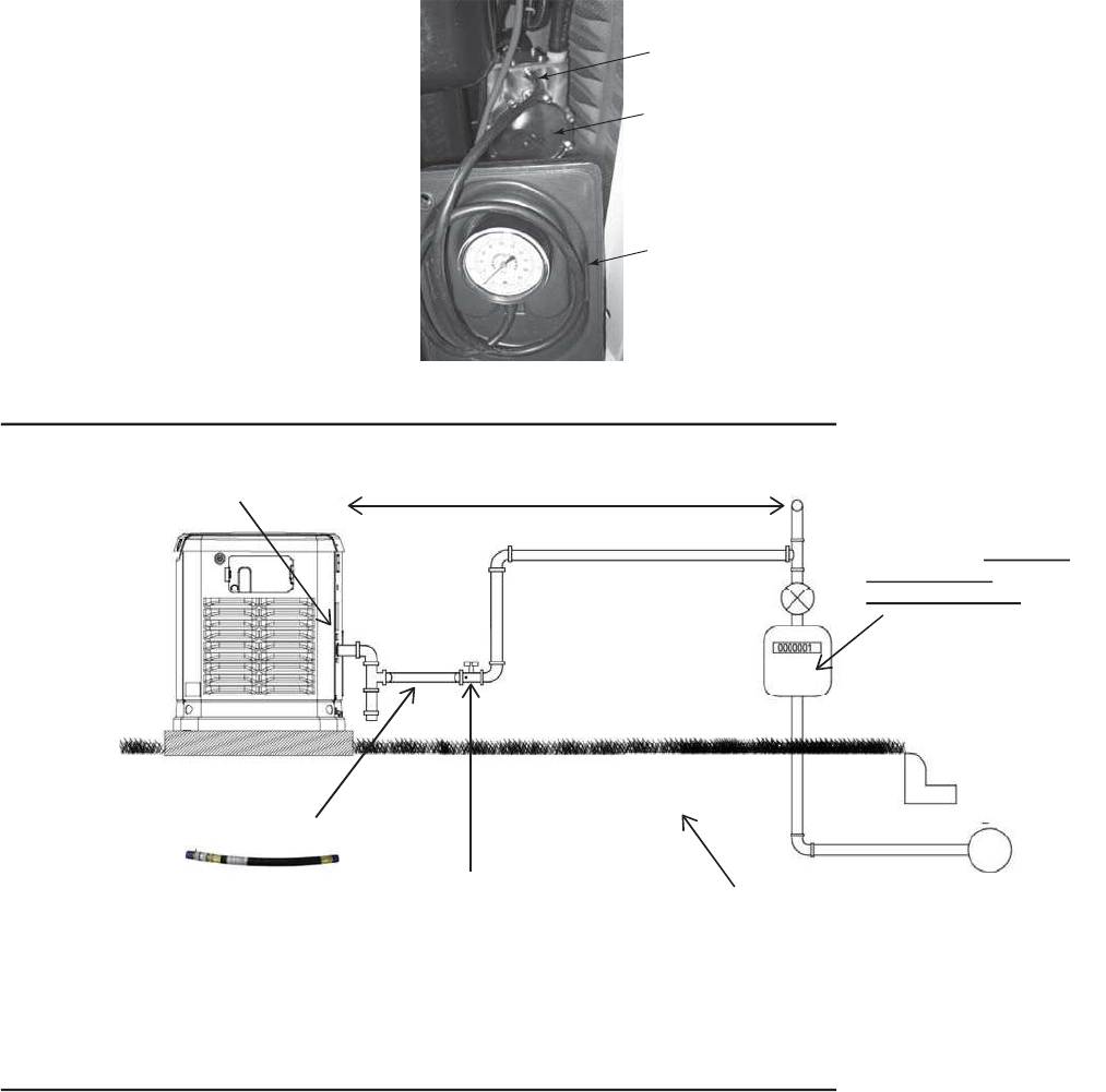
“blown away” or form “bubbles”. Next, check the gas pressure at the regulator in the generator by following these steps.
– Close gas supply valve.
– Remove the top gas pressure test port from the regulator (see Figure 5.6) and install the gas pressure tester (manometer).
– Open the gas supply valve and ensure that the pressure is within the specified values.
238)7IIS[RIVvWQERYEPSVWTIGWLIIXJSVTVSTIVJYIPTVIWWYVIWTIGMJMGEXMSRW-JXLIKEWTVIWWYVIMWRSX[MXLMRWTIGMJMGEXMSRWGSRXEGX
XLIPSGEPKEWWYTTPMIV
4) Close gas valve when completed.
8ST+EW4VIWWYVI
8IWX4SVX
*YIP6IKYPEXSV
+EW4VIWWYVI
1ERSQIXIV
*MKYVI{'LIGOMRK4VIWWYVI[MXL1ERSQIXIV
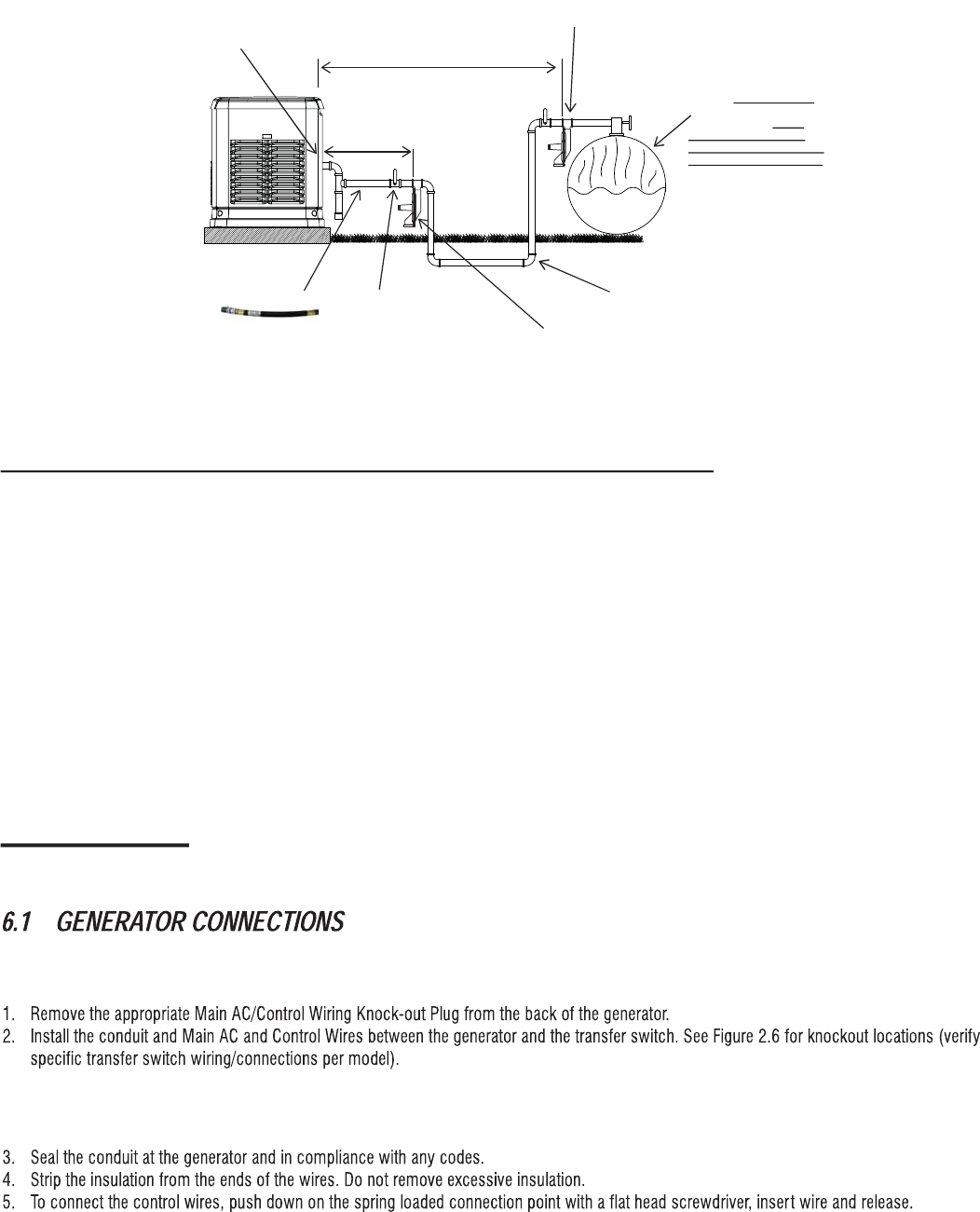
Size gas pipe with Pipe Sizing Guide or to local codes.
BTU and Pressure Decal Check Distance with Gas Provider
Size Meter for Generator
Load Plus ALL
Appliances Loads
For Underground Installations, Verify
Piping System for Code Compliance
Flex Fuel Line
Safety Shut-off with Pressure Port
NG - BTU = Cubic feet/hour X 1000
Megajoules = Cubic meters/hour X 37.26
*MKYVI{8]TMGEP2EXYVEP+EW:ETSV-RWXEPPEXMSR
21
Size gas pipe from secondary regulator with Pipe Sizing Guide or to local codes.
Check Distance with LP Provider
Fuel Tank
Flex Fuel Line High Pressure Pipe
sized per LP Provider
Check distance with
Regulator Manufacturer
Primary Regulator Per LP Provider
Full Flow Safety Shut-off
with Pressure Port
Size tank Large Enough
to provide required BTUs
for Generator and ALL
Connected Appliance
Loads. Be sure to correct
for Weather Evaporation.
LP - BTU = Cubic feet/hour X 2500
Megajoules = Cubic meters/hour X 93.15
Secondary-vented Regulator
BTU and Pressure Decal
*MKYVI{8]TMGEP04:ETSV-RWXEPPEXMSR
238);LIRWM^MRKEWIGSRHEV]VIKYPEXSVJSV04SVLMKLTVIWWYVIREXYVEPKEWETTPMGEXMSRWFIWYVIXSRSXIXLIQE\MQYQMRHMZMHYEPPSEH
GETEFMPMXMIW[LMGL[MPPFIPS[IVXLERXSXEPGETEGMX]8LMWGSYPHMQTEGXKIRIVEXSVWXEVXMRKTIVJSVQERGIMJWM^IHXSSWQEPP
238)-XMWRSXVIGSQQIRHIHXSVIHYGIXLIJYIPTMTIWM^II\MXMRKXLIWIGSRHEV]VIKYPEXSVYRPIWWRIGIWWEV]XSEGGSQQSHEXIXLI¡xSV¢x
JPI\MFPIJYIPPMRIXLEXMWWLMTTIH[MXLXLIKIRIVEXSV8LMWQE]TSXIRXMEPP]GEYWIWXEVXMRKSVTIVJSVQERGIMWWYIW
%JXIVGSQTPIXMRK+%76)59-6)1)287'322)'8-327
*9)0'32:)67-32MXvWXMQIJSV7XIT
7)'8-32{)0)'86-'%0'322)'8-327
Section 6 Electrical Connections
238)'SRXVSP[MVMRKQE]FIEPVIEH][MVIHSRTVI[MVIHKIRIVEXSVW-JWSXMKLXIRXLIv[LMTGSRHYMXMRWMHISJXLIIRGPSWYVI-JRSX[MVMRK
QYWXFIMREGGSVHERGI[MXLPSGEPNYVMWHMGXMSRERHGSHIW
238)8LIWI[MVMRKGSRRIGXMSRWQE]FITVIWIRXSRTVI[MVIHQSHIPW
238)8LMW[MVMRKGERFIVYRMRXLIWEQIGSRHYMXMJXLIETTVSTVMEXIMRWYPEXMSRVEXIH[MVIMWYWIH
238)2S[MVIMRWYPEXMSRWLSYPHFIMRXLIGSRRIGXMSRTSMRXSRP]FEVI[MVI
34
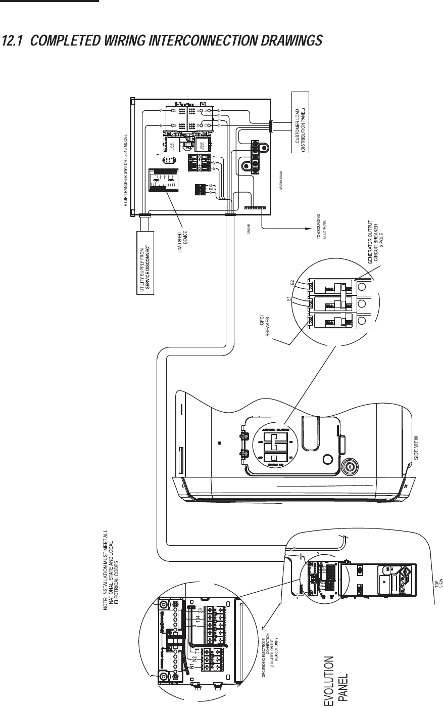
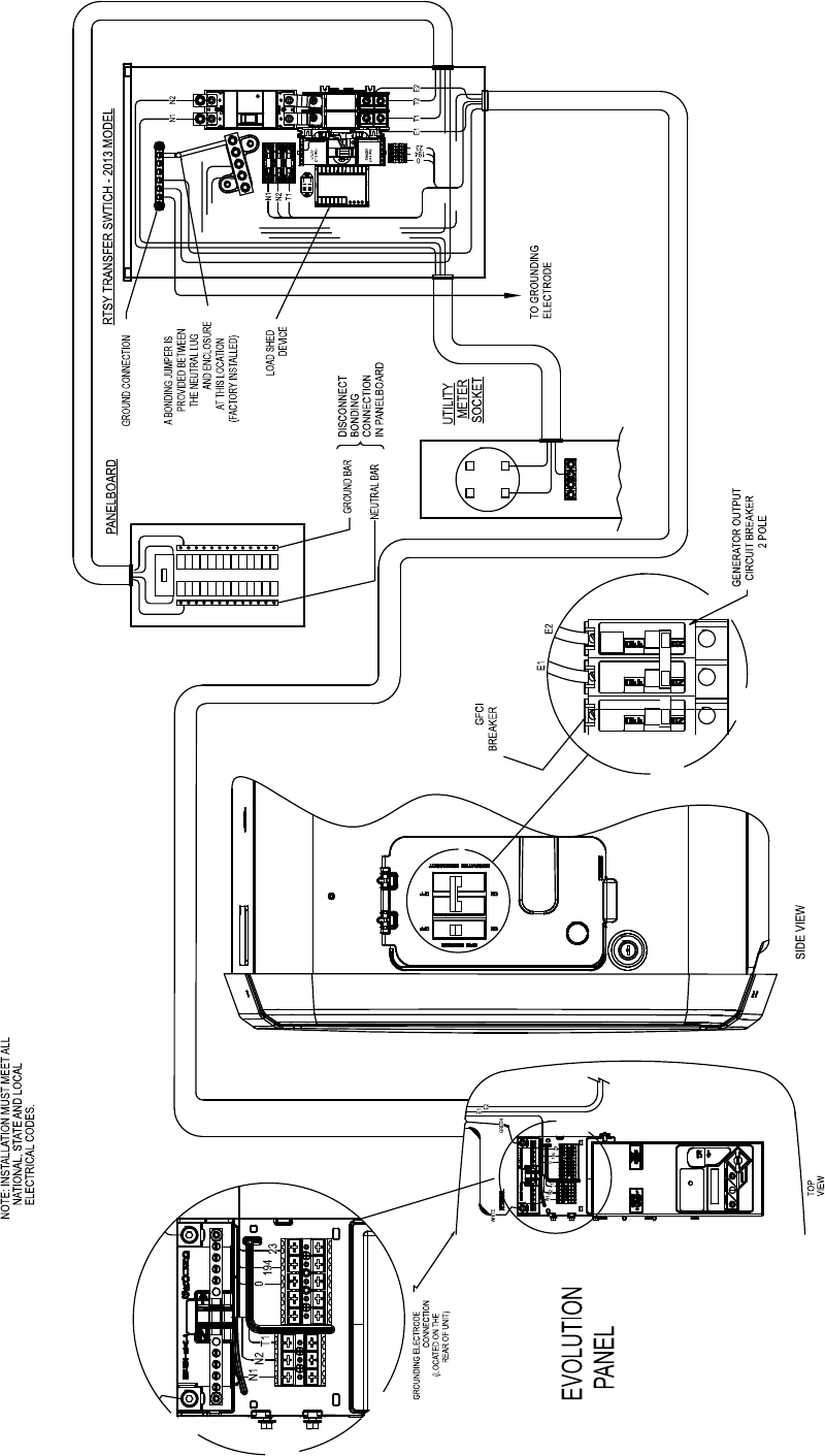
Section 12 Interconnection Diagram
The completed wiring is shown, depending on the confi guration of the transfer switch location (Drawing 0K2516-B).
35
36
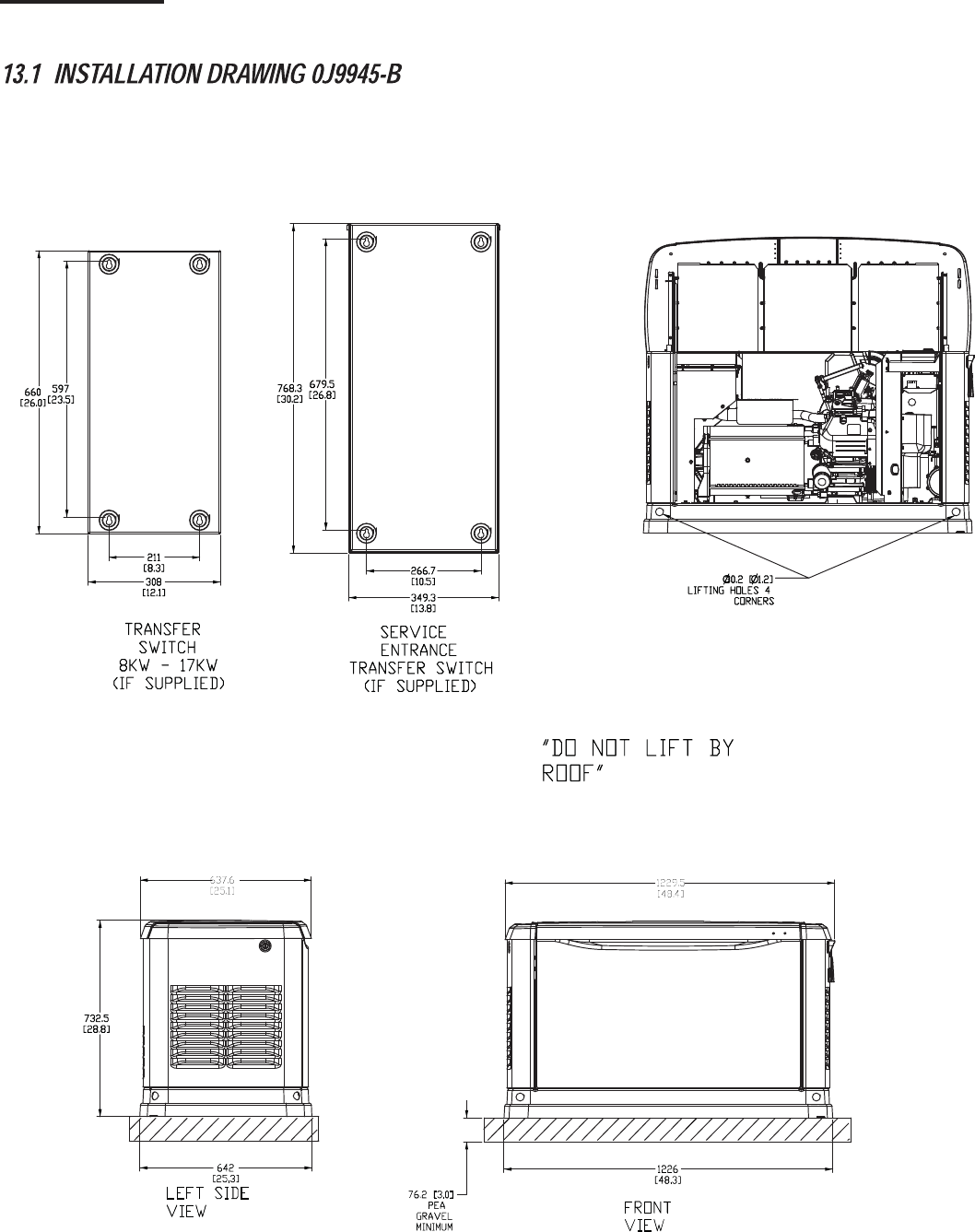
Section 13 Installation Diagram
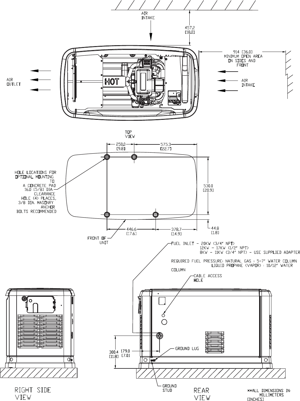
37
