536932 3 Paco Lcs End Suction Pump Installation Manual LC_LCV_LF_LCS User
536915 2 Paco Lcs End Suction Pump Installation Manual 536915_2_Paco LCS End Suction Pump Installation Manual
536918 2 Paco Lc End Suction Pump Installation Manual 536918_2_Paco LC End Suction Pump Installation Manual
536915 2 Paco Lcs Series End Suction Pump Installation Manual 536915_2_Paco LCS Series End Suction Pump Installation Manual 536915_2_Paco LCS Series End Suction Pump Installation Manual pdf pumpproducts
User Manual: Pump 536932 3 Paco Lcs End Suction Pump Installation Manual
Open the PDF directly: View PDF ![]() .
.
Page Count: 20
- English (US)
- 1. Symbols used in this document
- 2. Terms and Conditions
- 2.1 The contract
- 2.2 Price
- 2.3 Payment terms
- 2.4 Acceptance and inspection
- 2.5 Title and risk of loss
- 2.6 Patent or trademark information
- 2.7 Changes
- 2.8 Cancellation or termination
- 2.9 Delivery and delays
- 2.10 Warranty
- 2.11 Technical documents
- 2.12 Limitation of liability
- 2.13 This company is an equal opportunity employer
- 2.14 law and arbitration
- 3. Installation - Mechanical
- 3.1 Pump identification
- 3.2 Receiving
- 3.3 Temporary storage
- 3.4 Location
- 3.5 Horizontal pump foundation
- 3.6 Securing base plate
- 3.7 Vertical mounting instructions
- 3.8 Piping-general
- 3.9 Suction (inlet) piping
- 3.10 Discharge (outlet) piping
- 3.11 Shaft sealing-general comments
- 3.12 Packing gland adjustment
- 3.13 Mechanical seals
- 3.14 Coupling alignment (LF)
- 3.15 Coupling alignment (LCS)
- 4. Installation-electrical
- 5. Operation
- 6. Maintenance
- 6.1 Motor lubrication
- 6.2 Pump lubrication
- 6.3 Disassembly of pumps
- 6.4 Seal replacement (LCS)
- 6.5 Wear ring replacement
- 6.6 Reassembly of pumps
- 6.7 Ordering parts
- 6.8 Type LF, cross section and parts list
- 6.9 Type LC, cross section and parts list
- 6.10 Type LCV, cross section and parts list
- 6.11 Type LCS, cross section and parts
- 7. Trouble Shooting
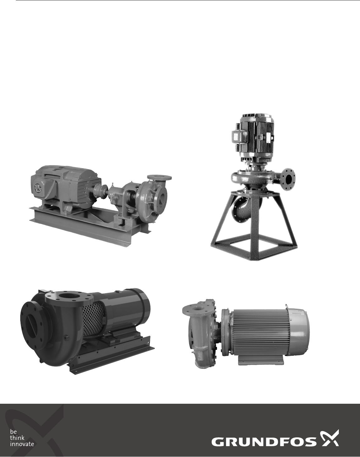
GRUNDFOS INSTRUCTIONS
LC, LCV, LF, LCS
End suction centrifugal pumps
Installation and operating instructions
English (US)
2
English (US) Installation and operating instructions
Original installation and operating instructions.
CONTENTS
Page
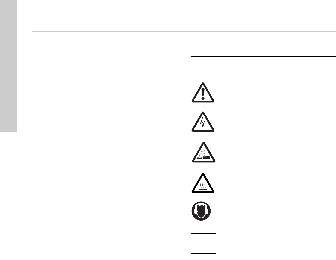
1. Symbols used in this document
The following symbols may be used in this document.
2. Terms and Conditions
2.1 The contract
The Contract shall be comprised of the following terms, together
with such terms and conditions as are set forth in Seller's written
proposal or quotation (the "Quotation"), including any documents,
drawings or specifications incorporated therein by reference, and
any additional or different terms proposed in Buyer's purchase
order (the "Purchase Order") that are accepted by Seller in
writing, which together shall constitute the entire agreement
between the parties, provided, however, that preprinted terms on
Buyer's purchase order or invoice shall not apply and Seller gives
notice of objection to such terms. An offer by Seller in its
Quotation that does not stipulate an acceptance date is not
binding. This Contract shall be deemed to have been entered into
upon written acknowledgment of the Purchase Order by an officer
or authorized representative of Seller, which may not be modified,
supplemented, or waived except in a writing executed by an
authorized representative of the party to be bound.
1. Symbols used in this document 2
2. Terms and Conditions 2
2.1 The contract 2
2.2 Price 3
2.3 Payment terms 3
2.4 Acceptance and inspection 3
2.5 Title and risk of loss 3
2.6 Patent or trademark information 3
2.7 Changes 3
2.8 Cancellation or termination 3
2.9 Delivery and delays 3
2.10 Warranty 4
2.11 Technical documents 4
2.12 Limitation of liability 4
2.13 This company is an equal opportunity employer 4
2.14 law and arbitration 5
3. Installation - Mechanical 5
3.1 Pump identification 5
3.2 Receiving 5
3.3 Temporary storage 5
3.4 Location 5
3.5 Horizontal pump foundation 5
3.6 Securing base plate 6
3.7 Vertical mounting instructions 6
3.8 Piping-general 6
3.9 Suction (inlet) piping 6
3.10 Discharge (outlet) piping 7
3.11 Shaft sealing-general comments 7
3.12 Packing gland adjustment 7
3.13 Mechanical seals 7
3.14 Coupling alignment (LF) 8
3.15 Coupling alignment (LCS) 8
4. Installation-electrical 8
4.1 Motors general 8
4.2 Installation wiring 8
5. Operation 9
5.1 Priming 9
5.2 Pre-start checklist 9
5.3 Motor rotation 9
5.4 Starting the pump 9
5.5 Voltage regulation 10
5.6 Pump shutdown 10
5.7 Short duration shutdown 10
5.8 Extended period shutdown 10
6. Maintenance 10
6.1 Motor lubrication 10
6.2 Pump lubrication 11
6.3 Disassembly of pumps 12
6.3.1 Disassembly of liquid end 12
6.3.2 Disassembly of bearing frame (LF) 12
6.4 Seal replacement (LCS) 12
6.5 Wear ring replacement 12
6.6 Reassembly of pumps 13
6.7 Ordering parts 13
6.8 Type LF, cross section and parts list 14
6.9 Type LC, cross section and parts list 15
6.10 Type LCV, cross section and parts list 16
6.11 Type LCS, cross section and parts 17
7. Trouble Shooting 18
7.1 Symptom 18
7.2 Possible Causes 18
Warning
If these safety instructions are not observed,
it may result in personal injury.
Warning
If these instructions are not observed, it may lead
to electric shock with consequent risk of serious
personal injury or death.
Warning
When pumping hazardous liquids, special
attention must be paid to the risk of personal
injury.
Warning
The surface of the product may be so hot that
it may cause burns or personal injury.
Warning
The sound pressure level is so high that hearing
protection must be used.
Caution
If these safety instructions are not observed,
it may result in malfunction or damage to the
equipment.
Note
Note
Notes or instructions that make the job easier
and ensure safe operation.

3
English (US)
2.2 Price
The price quoted in the Quotation shall be the Purchase Price
unless otherwise agreed in the Purchase Order. The Purchase
Price for equipment shall include packing for shipment. Field
Services shall be provided at Seller's standard rates. All other
costs, including packing for storage, freight, insurance, taxes,
customs duties and import/export fees, or any other item not
specified in the Contract, shall be paid by Buyer unless
separately stated in the Quotation and included in the price
quoted. Any sales, use, or other taxes and duties imposed on the
transaction or the equipment supplied shall be paid or reimbursed
by Buyer.
2.3 Payment terms
Payment shall be due within 30 days of the date of Seller's
invoice in U.S. funds unless otherwise agreed. If Buyer does not
observe the agreed dates of payment, Buyer shall pay interest to
Seller on overdue amounts at a rate that is the higher of: 9 % per
annum or a rate 5 % in excess of the rate borne from time to time
by new issues of six-month United States Treasury bills. Seller
shall be entitled to issue its invoice for the Purchase Price for
equipment upon the earlier of shipment, or notice to Buyer that
Seller is ready to ship, and for services, upon completion. If the
Purchase Price exceeds $250,000 USD, Buyer shall pay the
Purchase Price in Progress payments as follows: Fifteen percent
(15 %) upon submittal of general arrangement drawings, thirty
five percent (35 %) after receipt of first Bowl Casting, twenty
percent (20 %) after first case/bowl hydro test or bowl machining
and thirty percent (30 %) after notification of ready to ship.
2.4 Acceptance and inspection
All equipment shall be finally inspected and accepted by Buyer
within 14 days after delivery or such other period of time as is
agreed in the Purchase Order. Buyer shall make all claims
(including claims for shortages), excepting only those provided
for under the warranty clause contained herein, in writing within
such 14 day period or they are waived. Services shall be
accepted upon completion. Buyer shall not revoke its acceptance.
Buyer may reject the equipment only for defects that substantially
impair its value, and Buyer's remedy for lesser defects shall be in
accordance with Section 10, Warranty. If tests are made by Buyer
to demonstrate the ability of the equipment to operate under the
contract conditions and to fulfill the warranties in Section 10,
Buyer is to make all preparations and incur all expenses
incidental to such tests. Seller will have the right of representation
at such tests at its expense, and the right to technically direct the
operation of the equipment during such tests, including requiring
a preliminary run for adjustments.
2.5 Title and risk of loss
Full risk of loss (including transportation delays and losses) shall
pass to Buyer upon delivery, regardless of whether title has
passed to Buyer, transport is arranged or supervised by Seller, or
start-up is carried out under the direction or supervision of Seller.
Delivery shall be ex works, INCOTERMS 2000. Loss or
destruction of the equipment or injury or damage to the
equipment that occurs while the risk of such loss or damage is
borne by Buyer does not relieve Buyer of its obligation to pay
Seller for the equipment.
2.6 Patent or trademark information
If the equipment sold hereunder is to be prepared or
manufactured according to Buyer's specifications, Buyer shall
indemnify Seller and hold it harmless from any claims or liability
for patent or trademark infringement on account of the sale of
such goods.
2.7 Changes
Buyer may request, in writing, changes in the design, drawings,
specifications, shipping instructions, and shipment schedules of
the equipment. As promptly as practicable after receipt of such
request, Seller will advise Buyer what amendments to the
Contract, if any, may be necessitated by such requested
changes, including but not limited to amendment of the Purchase
Price, specifications, shipment schedule, or date of delivery. Any
changes agreed upon by the parties shall be evidenced by a
Change Order signed by both parties.
2.8 Cancellation or termination
Buyer shall have the right to cancel the Contract upon 15 days'
prior written notice to Seller, and Seller shall stop its performance
upon the receipt of such notice except as otherwise agreed with
Buyer. If Buyer cancels the Contract, it shall pay: (a) the agreed
unit price for equipment or components completed and delivered,
(b) additional material and labor costs incurred, and for
engineering services supplied by Seller with respect to the
canceled items, which shall be charged to Buyer at Seller's rates
in effect at the time of cancellation, but which shall not exceed the
contract price for such items, and (c) such other costs and
expenses, including cancellation charges under subcontracts, as
Seller may incur in connection with such cancellation or
termination.
2.9 Delivery and delays
Seller shall use its best efforts to meet quoted delivery dates,
which are estimated based on conditions known at the time 16
A1d.1 606 supercedes 9/05 PACO PUMPS of quotation. Seller
shall not be liable for any nonperformance, loss, damage, or
delay due to war, riots, fire, flood, strikes or other labor difficulty,
governmental actions, acts of God, acts of the Buyer or its
customer, delays in transportation, inability to obtain necessary
labor or materials from usual sources, or other causes beyond the
reasonable control of Seller. In the event of delay in performance
due to any such cause, the date of delivery or time for completion
will be extended to reflect the length of time lost by reason of
such delay. Seller shall not be liable for any loss or damage to
Buyer resulting from any delay in delivery.

English (US)
4
2.10 Warranty
Seller warrants that the equipment or services supplied will be
free from defects in material, and workmanship for a period of 12
months from the date of initial operation of the equipment, or 18
months from the date of shipment, whichever shall first occur. In
the case of spare or replacement parts manufactured by Seller,
the warranty period shall be for a period of six months from
shipment. Repairs shall be warranted for 12 months or, if the
repair is performed under this warranty, for the remainder of the
original warranty period, whichever is less. Buyer shall report any
claimed defect in writing to Seller immediately upon discovery
and in any event, within the warranty period. Seller shall, at its
sole option, repair the equipment or furnish replacement
equipment or parts thereof, at the original delivery point. Seller
shall not be liable for costs of removal, reinstallation, or gaining
access. If Buyer or others repair, replace, or adjust equipment or
parts without Seller's prior written approval, Seller is relieved of
any further obligation to Buyer under this section with respect to
such equipment or parts. The repair or replacement of the
equipment or spare or replacement parts by Seller under this
section shall constitute Seller's sole obligation and Buyer's sole
and exclusive remedy for all claims of defects. SELLER MAKES
NO OTHER WARRANTY OR REPRESENTATION OF ANY KIND
WITH RESPECT TO THE EQUIPMENT OR SERVICES OTHER
THAN AS SPECIFIED IN THIS SECTION 10. ALL OTHER
WARRANTIES, EXPRESS OR IMPLIED, INCLUDING BUT NOT
LIMITED TO, THE IMPLIED WARRANTIES OF
MERCHANTABILITY AND FITNESS FOR A PARTICULAR
PURPOSE, ARE HEREBY DISCLAIMED. For purposes of this
Section, the equipment warranted shall not include equipment,
parts, and work not manufactured or performed by Seller. With
respect to such equipment, parts, or work, Seller's only obligation
shall be to assign to Buyer any warranty provided to Seller by the
manufacturer or supplier providing such equipment, parts or
work. No equipment furnished by Seller shall be deemed to be
defective by reason of normal wear and tear, failure to resist
erosive or corrosive action of any fluid or gas, Buyer's failure to
properly store, install, operate or maintain the equipment in
accordance with good industry practices or specific
recommendations of Seller, or Buyer's failure to provide complete
and accurate information to Seller concerning the operational
application of the equipment.
2.11 Technical documents
Technical documents furnished by Seller to Buyer, such as
drawings, descriptions, designs and the like, shall be deemed
provided to Buyer on a confidential basis, shall remain Seller's
exclusive property, shall not be provided in any way to third
parties, and shall only be used by Buyer for purposes of
installation, operation and maintenance. Technical documents
submitted in connection with a Quotation that does not result in a
Purchase Order shall be returned to Seller upon request.
2.12 Limitation of liability
Seller shall in no event be liable for any consequential, incidental,
indirect, special or punitive damages arising out of the Contract,
or out of any breach of any of its obligations hereunder, or out of
any defect in, or failure of, or malfunction of the equipment,
including but not limited to, claims based upon loss of use, lost
profits or revenue, interest, lost goodwill, work stoppage,
impairment of other equipment, environmental damage, nuclear
incident, loss by reason of shutdown or nonoperation, increased
expenses of operation, cost of purchase of replacement power or
claims of Buyer or customers of Buyer for service interruption
whether or not such loss or damage is based on contract, tort
(including negligence and strict liability) or otherwise. Seller's
maximum liability under this Contract shall not exceed the
Purchase Order amount of the equipment or portion thereof upon
which such liability is based. All such liability shall terminate upon
the expiration of the warranty period, if not sooner terminated.
2.13 This company is an equal opportunity employer
This agreement incorporates by reference applicable provisions
and requirements of Executive Order 11246 and FAR Section
52.222-26 (covering race, color, religion, sex and national origin);
the Vietnam Era Veterans Readjustment Assistance Act of 1974
and FAR Section 52.222-35 (covering special disabled and
Vietnam era veterans); and the Rehabilitation Act of 1973 and
FAR Section 52.222-36 (covering handicapped individuals). By
acceptance of this agreement Buyer certifies that it does not and
will not maintain any facilities in a segregated manner, or permit
its employees to perform their services at any location under its
control where segregated facilities are maintained, and further
that appropriate physical facilities are maintained for both sexes.
Buyer agrees that it will obtain a similar certificate prior to award
of any nonexempt lower-tier subcontracts.
5
English (US)
2.14 law and arbitration
The Contract shall be governed by the law of the State of Texas.
Any disputes arising out of this Contract shall be resolved by
informal mediation in any manner that the parties may agree
within 45 days of written request for mediation by one party to the
other. Any dispute that cannot be resolved through mediation
shall be resolved by binding arbitration conducted in English in
Portland, Oregon under the Commercial Rules of the American
Arbitration Association except as otherwise provided in this
Section. The arbitration shall be conducted by three arbitrators
chosen in accordance with said Rules. The arbitrators are not
entitled to award damages in excess of compensatory damages.
Judgment upon the award may be entered in any court having
jurisdiction.
3. Installation - Mechanical
Read these instructions thoroughly before installing and
operating your PACO Type L Centrifugal Pump. Successful
operation depends on careful attention to the procedures
described in Sections 1, 2, 3 and 4 of this manual. Keep this
instruction manual handy for future use.
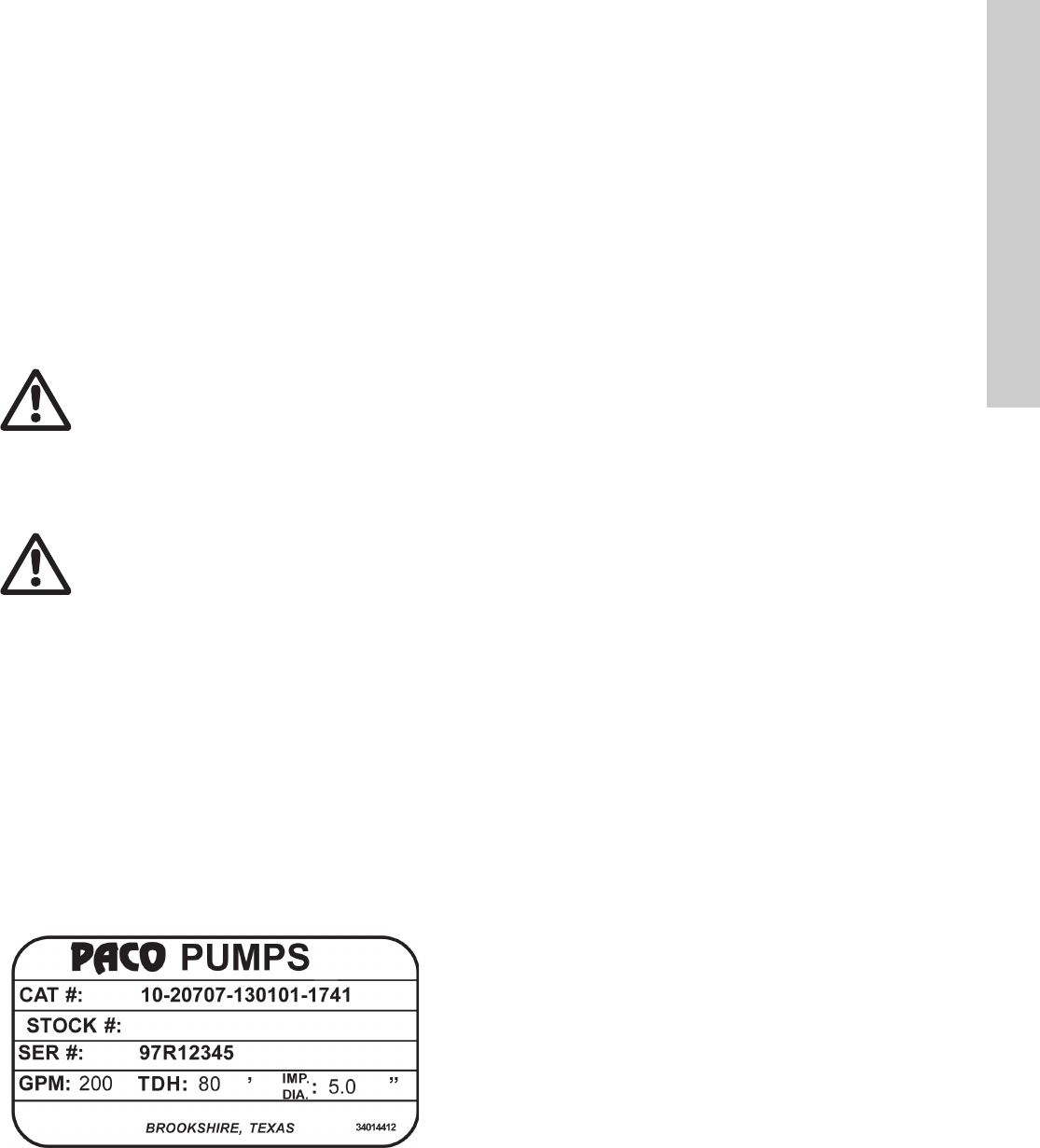
3.1 Pump identification
All PACO Pumps are identified by Catalog and Serial Numbers.
These numbers are stamped on the pump nameplate (Fig. 1)
affixed to each pump volute casing, and should be referred to in
all correspondence with the Company.
Fig. 1 Nameplate
3.2 Receiving
• Check pumping unit for shortage and damage immediately
upon arrival. Pump accessories when required are packaged
in a separate container and shipped with the unit.
• If equipment is damaged in transit, promptly report this to the
carrier's agent. Make complete notations on the freight bill to
speed satisfactory adjustment by the carrier.
• Unload and handle the unit with a sling. Do not lift unit by eye
bolts on the motor!
3.3 Temporary storage
• If pump is not to be installed and operated soon after arrival,
store it in a clean, dry area of moderate ambient temperature.
• Rotate the shaft by hand periodically to coat bearing with
lubricant to retard oxidation and corrosion.
• Follow motor manufacturer's storage recommendations where
applicable.
3.4 Location
• Locate the pump as close to the suction supply as possible.
Use the shortest and most direct suction piping practical.
Refer to 3.9 Suction (inlet) piping.
• Locate the pump below system level wherever possible. This
will facilitate priming, assure a steady liquid flow, and provide
a positive suction head.
• Make sure sufficient NPSH (Net Positive Suction Head) is
provided at the suction end by considering the pump's location
in relation to the entire system. Available NPSH must always
equal or exceed required NPSH specified on the pump
performance curve.
• Always allow sufficient accessibility for maintenance and
inspection. Provide a clear space with ample head room for
use of a hoist strong enough to lift the unit.
• Make sure a suitable power source is available for the pump
motor. Electrical characteristics should match those specified
on the motor data plate, within the limits covered in
4. Installation-electrical and 5. Operation.
• Avoid pump exposure to sub-zero temperatures to prevent
pump liquid from freezing. If freezing conditions exist during
shutdown periods, see Sections 5.6 Pump shutdownand
5.7 Short duration shutdown for specific recommendations.
3.5 Horizontal pump foundation
Horizontal pumps should be permanently installed on a firm,
concrete foundation mounting pad of sufficient size to dampen
any vibration and prevent any deflection or misalignment. The
pad may float on springs or be a raised part of the equipment
room floor. The foundation should be poured without interruption
to 3/4 to 1 - 1/2 inches below the final pump elevation. The top
surface should be well scored or grooved before the concrete
sets to provide a suitable bonding surface for the grout. Anchor
bolts should be set in pipe sleeves for positioning allowance, as
shown in Fig. 2. Allow enough bolt length for grout, lower base
plate flange, nuts and washers. Allow the foundation to cure
several days before proceeding with pump installation.
Warning
Prior to installation, read these installation and
operating instructions. Installation and operation
must comply with local regulations and accepted
codes of good practice.
Warning
The use of this product requires experience with
and knowledge of the product. Persons with
reduced physical, sensory or mental
capabilities must not use this product, unless
they are under supervision or have been
instructed in the use of the product by a person
responsible for their safety. Children must not
use or play with this product.
TM 05 8912 3712
English (US)
6
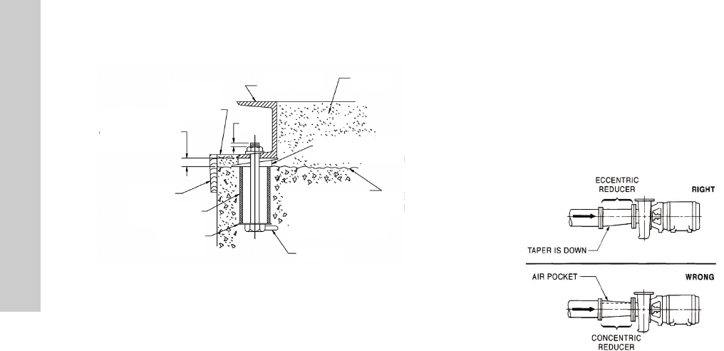
Fig. 2 Anchor bolt installation
3.6 Securing base plate
• After the concrete pad has been poured and set, lower the
pump base plate over the anchor bolts and rest it on loose
adjustment wedges or shims placed near each anchor bolt and
at intervals not to exceed 24" along each side. Shims or
wedges must be placed to raise the bottom of the base 3/4" to
1 - 1/4" above the pad, allowing clearance for grout. Level the
pump shaft, flanges, and base plate using a spirit level,
adjusting the wedges or shims, as required.
• Check to make sure that the piping can be aligned to the pump
flanges without placing any strain on either flange.
• After pump alignment has been established (LF), put nuts on
foundation bolts and tighten them just enough to keep the unit
base plate from moving. Construct a form or dam around the
concrete pad and pour grout in and around the pump base, as
shown in Fig. 2. Grout compensates for uneven foundation,
distributes the weight of the unit, and prevents shifting. Use an
approved, non shrinking grout (such as Embeco 636 by
Master Builders, Cleveland, Ohio or equivalent). Allow at least
24 hours for this grout to set before proceeding with piping
connections.
• After the grout has thoroughly hardened, check the foundation
bolts and tighten if necessary. Recheck the pump alignment
after the foundation bolts are secured.
• No alignment or grouting required for LCS pump.
3.7 Vertical mounting instructions
The PACO LCV Vertical Close Coupled pump need not be
grouted to its foundation, but should be anchored with 4 anchor
bolts set in concrete similar to the horizontal anchoring
arrangement Fig. 2.
3.8 Piping-general
• Do not use pump as a support for piping! Use pipe hangers or
other supports at proper intervals to provide complete piping
support near the pump.
• Both suction and discharge piping should be independently
supported and properly aligned so that no strain is transmitted
to the pump when flange bolts are tightened.
• Make sure piping is as straight as possible, avoiding
unnecessary bends and fittings. Where necessary, use 45 ° or
long-sweep 90 ° pipe fittings to decrease friction loss.
• Where flanged joints are used, make sure that inside
diameters properly match and mounting holes are aligned.
• Do not spring or force piping when making any connections!
3.9 Suction (inlet) piping
The sizing and installation of suction piping is particularly
important. It must be selected and installed in a manner that
minimizes pressure loss and permits sufficient liquid flow into the
pump during starting and operation. Many NPSH problems can
be traced directly to improper design of suction piping systems.
Observe the following precautions when installing suction piping:
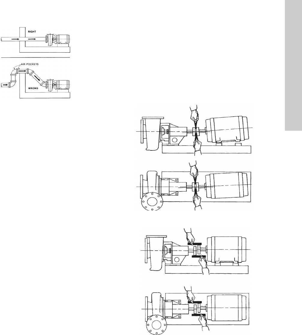
Fig. 3 Inlet piping
• Suction piping should be as direct as possible, and ideally the
length should be at least ten times the pipe diameter. Short
suction piping can be the same diameter as the suction
opening. Longer piping should be one or two sizes larger
(depending on length), reducing to the diameter of the pump
suction opening.
• Use an eccentric reducer, with the eccentric side down Fig. 3
when reducing the pipe diameter to the diameter of suction
opening.
• At no point should suction piping be smaller in diameter than
the pump suction opening.
• Horizontal suction lines should follow an even gradient, if
possible. A gradual upward slope to the pump is
recommended for suction lift conditions, and a gradual
downward slope for positive suction head.
• Avoid any high points, such as pipe loops Fig. 4, that may
create air pockets and throttle the system or produce erratic
pumping.
• Install a valve in the suction line to isolate the pump during
shutdown and maintenance, and facilitate pump removal.
Where two or more pumps are connected to the same suction
line, install duplicate gate valves to isolate each pump from
the line.
• Gate valves should always be installed in positions that avoid
air pockets. Globe valves should not be used, particularly
when NPSH is critical.
• During pumping operation, valves on suction line must always
be at FULL OPEN.
• Properly sized pressure gauges can be installed in gauge taps
on pump suction and discharge nozzles. Gauges enable the
operator to monitor pump performance and determine that the
pump conforms to the parameters of the performance curve. If
cavitation, vapor binding, or other unstable operation occurs,
pressure gauges will indicate wide fluctuation in suction and
discharge pressures.
TM 05 4775 2512
Finished
grouting
.75 to 1.25
allowance for grout
Dam
Pipe sleeve
Washer
Base plate Grout
Wedges or shims
left in place
Top foundation
leave rough clean
& wet down
LUG
TM05 4791 2613
7
English (US)
Fig. 4 Air pocket prevention
3.10 Discharge (outlet) piping
• Short discharge piping can be the same diameter as the pump
discharge opening. Longer piping should be one or two sizes
larger depending on length.
• An even gradient is best for long horizontal runs of discharge
piping.
• Install a valve near the discharge opening to prime and start
the pump. The discharge gate valve is also used to isolate the
pump during shutdown, maintenance, and facilitate pump
removal.
• Any high points in discharge piping may entrap air or gas and
thus retard pump operation.
• If the possibility of liquid hammer exists, (i.e. check valves are
used) close the discharge gate valve before pump shutdown.
3.11 Shaft sealing-general comments
• PACO offers both mechanical seals and packed stuffing boxes
as a means to seal the shaft. Pumps with stuffing boxes are
normally packed before shipment. If the pump is installed
within 60 days after shipment, the packing material will be in
good condition for operation with a sufficient supply of
lubrication. If the pump is stored for a longer period, it may be
necessary to repack the stuffing boxes.
• The stuffing box must be supplied at all times with a source of
clean, clear liquid to flush and lubricate the packing. When
pumps are equipped with mechanical seals, no maintenance
or adjustment is required. Mechanical seals are preferred to
packing on most applications because they require less
maintenance.
3.12 Packing gland adjustment
With the pump running, the packing gland should be adjusted to
permit 40 to 60 drops per minute leakage. This is required for
shaft lubrication. After initial start up, additional packing and
adjustment may be required. Pumps with mechanical seals
require no adjustment.
3.13 Mechanical seals
All PACO Type L pumps that are equipped with mechanical seals
are matched to conditions for which the pump was sold. Observe
the following precautions to avoid seal damage and obtain
maximum seal life:
• Do not exceed temperature or pressure limitations for the
mechanical seal used.
• DO NOT RUN THE PUMP DRY OR AGAINST A CLOSED
VALVE! Dry operation will cause seal failure within minutes.
• Clean and purge suction piping in new installations before
installing and operating pump. Pipe scale, welding slag and
other abrasives can cause rapid seal failure.
Fig. 5 Checking parallel alignment
Fig. 6 Checking alignment
TM05 4792 2613
TM05 4795 2613TM05 4794 2613
English (US)
8
3.14 Coupling alignment (LF)
• The following anchoring and alignment procedure is typical
and, if performed with care, should result in a smooth running,
trouble-free installation.
• If the pump and motor were shipped mounted on the pump
base as an assembly, remove the coupling guard.
• The pump and motor were accurately aligned at the factory,
but handling during shipment usually alters this pre-alignment.
Using a small straight edge and feeler gauges or a dial
indicator, check for horizontal, vertical, and angular
misalignment of the coupling hubs Fig. 5 and Fig. 6.
• Coupling alignment is correct when the dial indicator reads no
more than .005" run out in any direction (or when the straight
edge contacts both hubs evenly in both horizontal and vertical
positions). If misalignment is detected, loosen the motor and
shift or shim as necessary to re-align, then re-tighten bolts.
Always align the motor to the pump as piping strain will occur
if the pump is shifted. Never reposition pump on base!
• After final piping connections to the pump have been made,
motor wiring compared, correct rotation has been established,
and piping filled with liquid, check shaft alignment once again.
• Leave the coupling guards off until the pump priming
procedure is completed for a final shaft alignment check.
• To protect personnel from rotating machinery, Always install
coupling guards after installation is complete; before starting
pump!
3.15 Coupling alignment (LCS)
• No alignment of the pump and motor is required.
4. Installation-electrical
4.1 Motors general
the motor control circuit must have the following components in
order to comply with the National Electrical Code.
• Motor Disconnecting Device: A motor disconnecting device
must be installed that is capable of disconnecting both the
controller (motor starter) and the motor from their source of
power.
• The disconnecting device must be located so that the
controller (motor starter) can be seen from the disconnecting
means. In all cases, the distance from the disconnecting
device to the controller must be less than 50'.
• In most installations the disconnecting device will be a circuit
breaker or fusible disconnect switch.
Motor short circuit and ground fault protection:
• Short circuit and ground fault protection are usually provided
by means of a circuit breaker or fusible disconnect switch.
• The selection of the size of the circuit breaker or fuse must be
in accordance with Section 430-52 and Table 430-152 of the
National Electrical Code.
Motor controller with running over current protection (magnetic
starter):
• These components must be installed in accordance with
applicable local and state electrical codes in addition to the
National Electrical Code.
4.2 Installation wiring
• Mount the control panel or motor starter(s) in close proximity
to the pump to provide convenient control and ease of
installation.
• Wire panel or starter(s) to motor(s) and pilot device(s): Wires
to each motor must be sized for at least 125 % of the motor
nameplate full load amps. AWG #16 Type THW stranded wire
is recommended for wiring of pilot devices (float switches).
• Check incoming power source to ensure that it is the same as
the voltage and phase of the motors.
• Verify that the starters are suitable to operate the pump motors
on voltage and phase that is available.
Warning
Use only qualified electricians for electrical
installation and maintenance.
Refer to manuals provided with electrical
accessory components and disconnect power
supply as recommended for servicing.
Warning
Never do maintenance work when the unit is
connected to power.
Warning
Whenever powered equipment is being used in
explosive surroundings, the rules and
regulations generally or specifically imposed by
the relevant responsible authorities or trade
organizations must be observed.
9
English (US)
5. Operation
5.1 Priming
• The PACO Type L pump is not self-priming, and must be
completely primed (filled with liquid) before starting.
• If the pump will operate with a positive suction head, prime by
opening the suction valve and allowing liquid to enter pump
casing. Open air vents at this time, and make sure all air is
forced from pump by liquid before closing.
• Rotate the shaft by hand to free entrapped air from impeller
passageways.
• If pump has a suction lift, priming must be accomplished by
other methods. The use of foot valves or ejectors, or manual
filling of the pump casing and suction line with liquid are
possible methods suggested for this purpose.
• CAUTION: Never run the pump dry in the hope that it will
prime itself! Serious damage to the mechanical seal will result.
5.2 Pre-start checklist
Make the following inspections before starting your PACO Type L
pump:
1. Make sure the suction and discharge piping has been cleaned
and flushed to remove dirt and debris before operating pump.
2. Double check rotation must be clockwise operating in reverse
will destroy the impeller and shaft.
3. Make sure all wiring connections to the motor (and starting
device) match the wiring diagram and produce clockwise
rotation as viewed from the back of the motor.
4. If the motor has been in storage for an extended length of
time, either before or after installation, refer to motor
instructions before starting.
5. Check the voltage, phase, and line circuit frequency with the
motor nameplate. Turn rotating element by hand to make sure
it rotates freely.
6. Tighten plugs in gauge and drain taps. If the pump is fitted
with pressure gauges, keep gauge clocks closed when not in
use.
7. Check suction and discharge piping for leaks, and make sure
all flange bolts are securely tightened.
5.3 Motor rotation
After the unit has been wired and checked to insure that all
components in the system (disconnect device, magnetic starters,
pilot devices and motors) are properly connected, check motor
rotation as follows:
• For 3 phase units only—momentarily energize the motors to
ensure that the rotation is correct as indicated by the arrow
cast into the pump volute. If rotation is incorrect, interchange
two wires at the motor starter terminals T1 and T2.
• IMPORTANT: The pumps must not be operated while dry. Use
extreme caution that motors are energized only momentarily to
determine proper rotation.
5.4 Starting the pump
1. Install coupling guard on coupled units.
2. Fully open gate valve (if any) in suction line, and close gate
valve in discharge line.
3. Fill suction line with liquid and completely prime pump.
4. Start the motor (pump).
5. Immediately make a visual check of pump and suction piping
for pressure leaks.
6. Immediately after pump reaches full operating speed, slowly
open the discharge gate valve until complete system flow is
achieved.
7. Check discharge piping for pressure leaks.
8. If pump is fitted with pressure gauges, open gauge cocks and
record pressure reading for future reference. Verify that the
pump is performing in accordance with parameters specified
on performance curve.
9. Check and record voltage, amperage per phase, and
kilowatts, if a wattmeter is available.
Caution
Never run the pump dry in the hope that it will
prime itself! Serious damage to the shaft seals,
pump wear rings and shaft sleeves will result.
Warning
In the interest of operator safety, the unit must
not be operated above the nameplate conditions.
Such operation could result in unit failure
causing injury to operating personnel. Consult
instruction book for proper operation and
maintenance of the pump and its supporting
components.
Caution
Never check driver rotation unless pump and
driver couplings are disconnected and physically
separated. Failure to follow this instruction can
result in serious damage to pump and driver if
rotation is wrong.
Warning
The pump must not be operated without an
approved coupling guard in place. Failure to
observe this warning could result in injury to
operating personnel.
English (US)
10
5.5 Voltage regulation
The motor will operate satisfactorily under the following
conditions for voltage and frequency variation, but not necessarily
in accordance with the standards established for operation under
rated conditions:
• The voltage variation may not exceed 10 % above or below
rating specified on the motor data plate.
• The frequency variation may not exceed 5 % above or below
motor rating.
• The sum of the voltage and frequency variations may not
exceed 10 % above or below motor rating, provided the
frequency variation does not exceed 5 %.
5.6 Pump shutdown
The following shutdown procedures will apply in most normal
shutdowns for the PACO Type L pumps. If the pump will be
inoperative for an extended length of time, follow storage
procedures in Extended Period Shutdown.
• Always close the discharge valve before stopping the pump.
Close the valve slowly to prevent hydraulic shock.
• Cut and lock off power to the motor.
5.7 Short duration shutdown
• For overnight or temporary shutdown periods under non-
freezing conditions, the pump may remain filled with liquid.
Make sure the pump is fully primed before restarting.
• For short or frequent shutdown periods under freezing
conditions, keep fluid moving within the pump casing and
insulate or heat the pump exterior to pre vent freezing.
5.8 Extended period shutdown
• For long shutdown periods, or to isolate the pump for
maintenance, close suction gate valve. If no suction valve is
used and the pump has positive suction head, drain all liquid
from suction line to terminate liquid flow into pump suction
nozzle. Remove plugs in pump drain and vent taps, as
required, and drain all liquid from the pump volute casing.
• If freezing conditions will exist during long shutdown periods,
completely drain the pump and blow out all liquid passages
and pockets with compressed air. Freezing of pump liquid can
also be prevented by filling the pump with antifreeze solution.
6. Maintenance
Before attempting any inspection or repair on the pump, the driver
controls must be in the "OFF" position, locked and tagged to
prevent injury to personnel performing service on the pump.
6.1 Motor lubrication
Always follow motor manufacturer's lubrication instructions if
available, and periodically check grease fittings and drain plugs
for leaks. If lubricating instructions do not accompany motor, refer
to for recommended lubrication periods.
• To lubricate the motor while running or at rest, remove grease
drain plug (if any) and filler plug on grease fitting. Grease with
clean lubricant until grease appears at drain hole or along
motor shaft.
• One-half to one cubic inch of grease is sufficient for motors 5
HP and under, with proportionately more grease for greater
HP motors.
• Most fractional and some integral frame motors have "sealed-
for-life" bearings, and do not require further lubrication
throughout motor life.
• Always follow motor manufacturer's lubrication instructions,
and periodically check grease fittings and drain plugs for
leaks.
• If lubricating instructions do not accompany motor, refer to
Table , “Recommended Lubrication Periods,” on page 10 for
recommended lubrication periods.
• Table , “Approved lubricants,” on page 11 lists recommended
types of grease for both pump and motor lubrication. These
types have all been thoroughly tested and should be used
whenever possible.
Warning
Do not attempt any maintenance, inspection,
repair or cleaning in the vicinity of rotating
equipment. Such action could result in personal
injury to operating personnel.
Recommended Lubrication Periods
Motor RPM Motor HP Operating conditions
Standard Severe Extreme
1750 and
below
0.33 - 7.50p 3 yrs 1 yr 6 mo
10-40 1-3 yrs 6 mo - 1 yr 3 mo
50-150 1 yr 6 mo 3 mo
200 and up 1 yr 6 mo 3 mo
above 1750 all hp 6 mo 3 mo 3 mo
Standard conditions:
8 Hours per day operation, normal or light loading, clean air,
100 °F, maximum ambient temperature.
Severe conditions:
Continuous 24-hour operation, shock loading or vibration, poor
ventilation, 100-150 °F, ambient temperature.
Extreme conditions:
Continuous operation, heavy shock or vibration, dirt or dust in
air, extreme ambient temperature.
11
English (US)
6.2 Pump lubrication
• PACO Type LF pumps on horizontal bearing frames have
bearing that may be sealed for life (requiring no lubrication),
regreasable or oil lubricated.
.
• To lubricate regreasable bearings, remove grease drain plug
(if any) and filler plug. Add clean ball bearing lubricant until
grease appears at drain hole or along shaft. On units with
drain hole, all old grease can be purged out ahead of new. In
such cases, the drain should be left unplugged for several
minutes during pump operation to allow excess grease to be
forced out.
• Lubricate bearing frame bearings at intervals of one to three
months, depending on severity of environment. Pumps in a
clean, dry, moderate temperature (100 °F maximum)
environment should be regreased at three month intervals.
Too much grease can cause premature bearing failure-do not
overgrease.
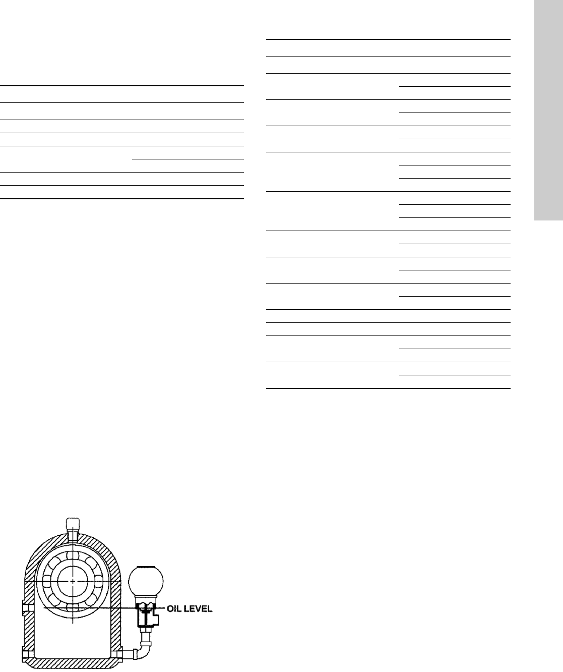
• On those PACO Type LF Centrifugal End Suction pumps
ordered with oil lubricated bearings, Fig. 7. A regular oil
maintenance program must be enforced. Pumps with oil
lubricated bearings are fitted with a transparent reservoir
(constant level oiler) that maintains oil level about the
centerline of the bearing. When necessary, the oil supply in
the reservoir of the constant level oiler must be renewed.
• After the first 200 hours of operation the oil should be
changed. To change the oil, remove the drain plug at the
bottom of the bearing cover and the filler plug (that also acts
as a vent plug) at the top of the housing. After draining oil,
replace the fittings and refill with an acceptable oil selected
from Table , “List of acceptable Lube oils,” on page 11. After
the first oil change, the oil should be changed again at 2000
hours and then at intervals of 8000 hours or once yearly,
thereafter.
Fig. 7
Approved lubricants
MANUFACTURER LUBRICANT
SHELL DOLIUM® R
EXXON POLYREX®
CHEVRON SRI GREASE NLGI 2
BLACK PEARL - NLGI 2
PHILIPS POLYTAC™
TEXACO POLYSTAR RB
TM05 4793 2613
List of acceptable Lube oils
Lubricant Manufacturer Bearing oil brand name
Aral Refining Co. Aral Oil CMU
Aral Oil TU 518
British Petroleum Co. BP Energol
TH 100-HB
Calypsol Oil Co. Calypsol Bison Oil
SR 25 or SR 36
Standard Oil Co.
Chevron
Hydraulic Oil 11
Circulating oil 45
Esso Corp
Esso-Mar 25
Teresso 47
Esstic 50
Fina Oil Co. Fina hydran 34
Fina Cirkan 32
Gulf Refining Co. Gulf Harmony 47
Gulf Paramount 45
Socony Mobil Oil Co. Vac hlp 25
Mobulix D.T.E. 25
Shell Oil Co. Shell Tellus oil 29
Sundco Oil Co. Sunvis 821
The Texas Co. Texaco ursa oil P 20
Dea viscobil sera 4
Wisura Refining Co. Wisura norma 25 (36)
Wisura tempo 25 (36)
English (US)
12
6.3 Disassembly of pumps
1. Complete disassembly instructions are outlined below.
Proceed only as far as required to perform the maintenance
work needed.
2. Turn of power.
3. Drain System. Flush, if necessary.
4. Closed coupled units. Remove motor hold down bolts.
6.3.1 Disassembly of liquid end
1. Remove casing bolts (8B).
2. Remove back pull-out bearing frame assembly (20Y) from
casing (1A).
3. Unscrew impeller nut (8A).
4. Use appropriate size gear puller aligned behind impeller
vanes to remove impeller (3A) from shaft (6A).
5. Remove impeller key (12A).
6. Remove back plate bolts (8D). Remove back plate (2K) and
seal housing (26P).
7. Place seal housing on flat surface and press out seal seat
(14A).
8. If shaft sleeve (5A) requires replacement, it must be evenly
heated to approximately 350 °F to loosen locktite. Twist
sleeve off shaft (6A).
6.3.2 Disassembly of bearing frame (LF)
1. Remove slinger (13G).
2. Remove grease seal(s), (14S) if any.
3. Remove bearing house retaining ring (61K).
4. Press or tap on the pump end of the bearing-shaft assembly
until one bearing is out.
5. When one bearing is out, remove second retaining ring (61F),
then remove complete assembly from bearing housing.
6. Remove shaft retaining ring (61C) and press off bearings.
7. press on new bearings, remember to press only on inner race
of bearing while pressing them on.
8. Assemble frame in the reverse procedure used for
disassembly.
9. Observe the following when reassembling the bearing frame.
10. Replace lip seals (14S) if worn or damaged.
11. Replace bearings (18A), (18B) if loose, rough or noisy when
rotated.
12. Check shaft (6A) for runout at the sleeve (5A) area. Maximum
permissible is .002" T.I.R.
6.4 Seal replacement (LCS)
1. Complete preparations noted.
2. Remove coupling guard (34F).
3. Remove coupling bolts (8E). Pry apart the coupling halves
(23D), remove keys (12B) and set aside.
4. Unscrew tubing connector from pipe tee of air vent assembly.
Pipe dope is applied to threads during factory assembly, and
resulting bond may retard but will not prevent manual
disassembly.
5. Remove seal cap bolts and slide seal cap (2N) up shaft to
remove.
6. Remove seal head assembly manually from shaft (6A).
Water-soluble lubricant may be applied to shaft to ease
removal of shaft seal (14A). Pull seal head assembly
manually from shaft, using slight twisting motion (as
necessary) to loosen bellows from shaft.
7. Remove and discard seal spring and retainer.
8. remove and discard seal seat from seal cap (2N) and
thoroughly clean the inside cavity of seal cap.
9. Interior surface of bellows on new seal head is coated with
bonding agent that adheres to motor shaft. When old seal
head is removed, bonding agent no longer exists and bellows
may crack or split during removal. Installation of new
mechanical seal is always recommended if it becomes
necessary to remove existing seal from shaft.
10. Clean and lubricate shaft (6A) with water-soluble lubricant
and make sure no sharp edges exist to cut or scratch bellows
of new seal.
11. Press new seal seat firmly into seal cap. Avoid direct contact
of seal face with metallic or abrasive objects and wipe clean
after installation to ensure abrasive free sealing surface.
12. Slide new seal head assembly onto shaft by applying even
pressure to base of assembly.
13. Install seal cap (2N) down shaft.
14. See reassembly instructions.
6.5 Wear ring replacement
1. Complete preparations.
2. Back-pull rotating assembly.
3. It may be necessary to remove volute (1A) from piping, to
facilitate easy access to interior of volute. If necessary,
remove flange bolts at piping.
4. To remove worn Case Wear Ring (4A), drill two holes slightly
smaller than width of ring into exposed edge of ring. Once
holes are drilled, a chisel may be used to completely sever
ring at holes and break ring into two halves for easy removal.
5. Clean the ring cavity in the volute prior to installing wear ring
to ensure a properly aligned fit.
6. To reassemble, press fit new wear ring squarely into volute
casing cavity. Ring may be tapped into place to make sure it
is completely impressed into cavity.
Warning
Depending on the product being pumped, the
pump should be washed down before any work is
done on it.
Warning
Observe extreme caution when venting and/or
draining hazardous liquids. Wear protective
clothing in the presence of caustic, corrosive,
volatile, flammable, or hot liquids. DO NOT
breathe toxic vapors. DO NOT allow sparking,
flames, or hot surfaces in vicinity of the
equipment.
Caution
Do not screwdriver between impeller vanes to
prevent rotation. It may be necessary to use a
strap wrench around the impeller or shaft to
prevent rotation.
Note
Note
Mark or measure the original position of the
pump coupling on the motor side.
Caution
Do not use metal tooling against wear ring
surfaces. Use only rubber, rawhide, wood or
other soft material to prevent damage to ring.

13
English (US)
6.6 Reassembly of pumps
1. All parts should be cleaned before reassembly.
2. Refer to parts list to identify required replacement items
Specify pump serial or catalog number when ordering parts.
3. Reassembly is the reverse of disassembly.
4. Observe the following when reassembling the liquid end:
• All mechanical seal components must be in good condition or
leakage may result. Replacement of complete seal assembly
is recommended.
• New shaft sleeves are installed by bonding to shaft with
hydraulic setting locktite.
5. Re-install coupling guards on coupled pumps.
6.7 Ordering parts
Grundfos Pumps has over 90 years of experience in the design,
manufacture, and application of centrifugal pumps and pumping
systems. Grundfos's commitment to state-of-the-art pump design
and quality manufacturing assures maximum user benefits with
optimum equipment life at lower cost.
Grundfos's commitment to their customers continues through an
extensive service organization. Highly trained technicians can
assist customers with initial startup, troubleshooting, repair, and
system analysis.
PACO maintains an extensive stock of replacement parts and
parts kits for our most popular model pumps. Shipment of these
parts is normally made within three days after receipt of an order.
On larger pumps, where it is impractical for our factory to
inventory low usage parts, replacement parts are normally
manufactured and shipped within 15 working days of receipt of an
order. In order to reduce pump repair time and shorten
inconvenient pump service interruptions, it is suggested that the
pump user stock spare parts. For suggested spare parts see
Replacement Parts Guide A1b.2, attached, and contact your local
PACO Sales Representative (see back cover for the number of
your nearest PACO Sales office). Since spare parts requirements
and quantities vary for specific pump constructions, allow your
PACO Representative to help in defining your spare part
requirements. To ensure that the proper replacement parts are
ordered for your particular pump model, when you call:
• Identify all pertinent data from the pump name plate (see
Pump Identification ). This should always include the pump
Catalog or Model Number, and the pump Serial Number.
• For replacement impellers, also include from the nameplate
the operating conditions (GPM and TDH) and the impeller
diameter.
• Identify all parts by item number and description as indicated
by the appropriate assembly drawing in this manual, for your
particular pump model.
Warning
Coupling guard must be reinstalled and in place
prior to operation.
English (US)
14
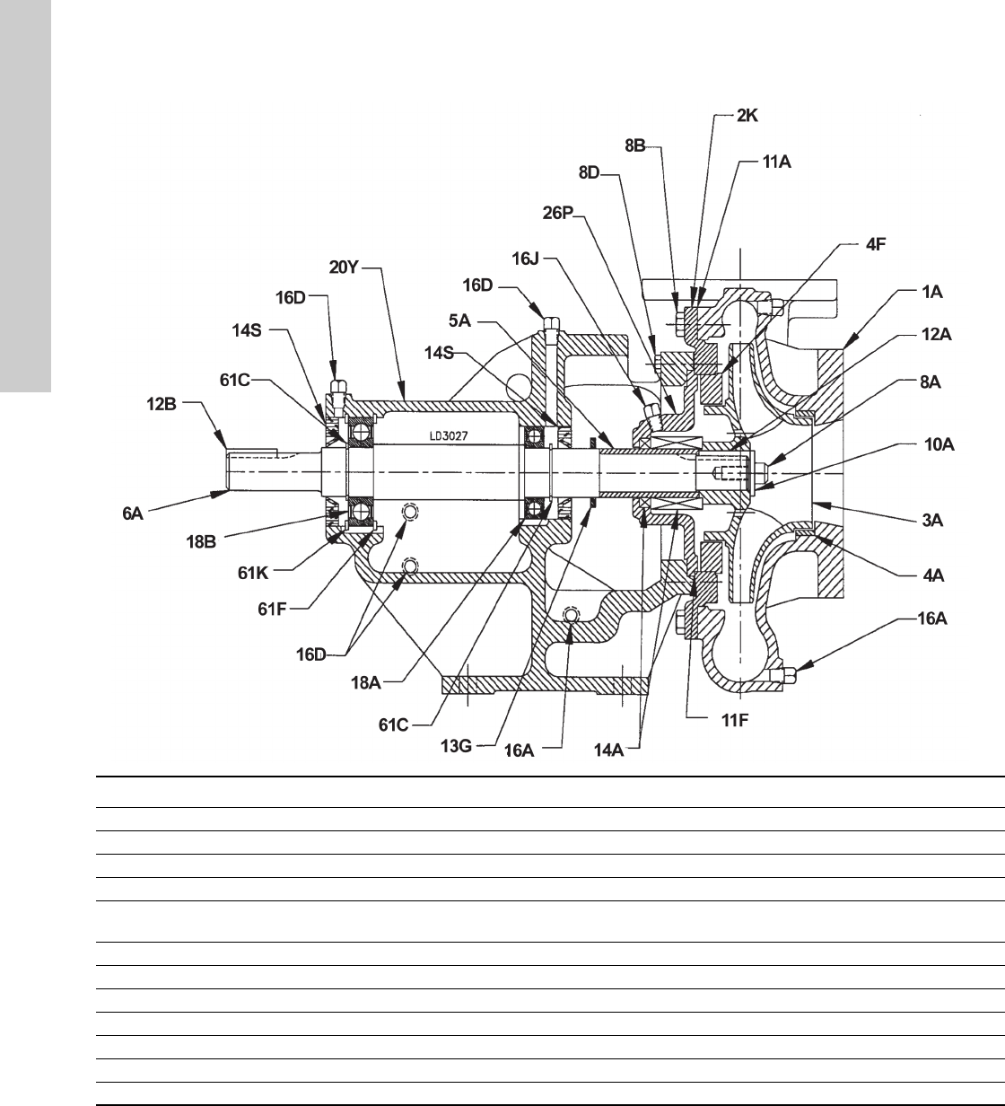
6.8 Type LF, cross section and parts list
* Packed Pumps Only
** If Applicable
TM05 4796 3712
ITEM NO PART NAME ITEM NO PART NAME ITEM NO PART NAME
1A Casing *10A Washer, Packing 16L Plug, Seal Chamber
2K Backplate 10A Washer, Impeller 18A Bearing, Inboard
3A Enclosed Impeller 11A Gasket, Casing 18B Bearing, Outboard
4A Case Wear Ring 11F Gasket, Backplate 20Y Bearing Frame
**4F Balance Ring 12A Key, Impeller *22A
Stud, Packing
Gland
5A Shaft Sleeve 12B Key, Coupling 26P Seal Housing
*5L Lantern Ring *13A Packing *26U Packing Box
6A Shaft 13G Slinger *35F Nut, Packing Gland
*7A Packing Gland 14A Shaft Seal 61C Snap Ring
8A Cap Screw, Impeller 14S Lip Seal *61J Snap Ring
8B Cap Screw, Casing 16A Plug, Drain
8D Cap Screw, Brg. Frame 16D Plug, Grease/Oil Filter
15
English (US)
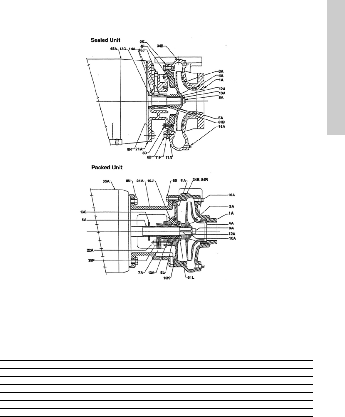
6.9 Type LC, cross section and parts list
* Packed pumps only
TM05 8911 2913
ITEM NO PART NAME ITEM NO PART NAME
*1A Casing 11F Gasket, backplate
2K Backplate 12A Key
3A Impeller *13A Packing
4A Front case wear ring 13G Slinger
4F Rear case wear ring 14A Mechanical seal
5A Shaft sleeve 16A Plug, drain
*5L Lantern ring 16J Plug, stuffing box
*7A Packing gland 21A Bracket
8A Impeller capscrew *22A Stud, packing gland
8B Capscrew, casing 34B Nameplate
8D Capscrew, bracket *35F Nut, packing gland
8N Capscrew, motor 61B Snap ring
10A Washer, impeller *61L Retaining ring
*10K Washer, packing 65A Motor
11A Gasket, casing 84R Set screws
English (US)
16
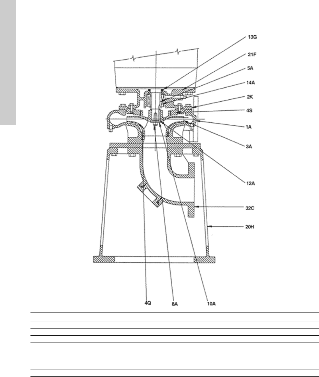
6.10 Type LCV, cross section and parts list
TM05 8910 2913
ITEM NO PART NAME ITEM NO PART NAME
1A Volute 10A Impeller washer
2H Hand hole cover (not shown) 12A Key
2K Backplate 13G Slinger
3A Impeller 14A Single mechanical seal assembly
4Q Suction cover wear ring 20H Stand
4S Impeller wear ring 21F Pedestal bracket
5A Sleeve 32C Elbow with clean out port
8A Impeller screw
17
English (US)
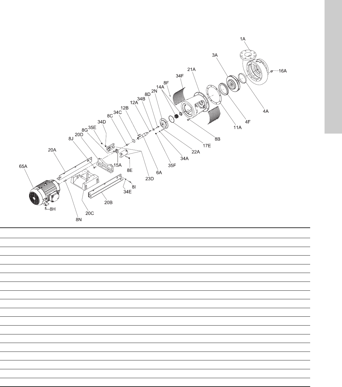
6.11 Type LCS, cross section and parts
TM06 1700 2614
ITEM NO PART NAME ITEM NO PART NAME
1A VOLUTE 17E SEAL CAP O-RING
2N SEAL CAP 20B BASE RAIL
3A IMPELLER 20C MOTOR DECK
4A CASE WEAR RING 20J CAST IRON STAND
4F BALANCE RING 20D PUMP SUPPORT
6A PUMP SHAFT 21A MOTOR BRACKET
8B VOLUTE SCREW 22A SEAL CAP STUDS
8C PUMP SHAFT SCREW 23D COUPLING HALVES
8E COUPLING SCREW 24H BUSHING
8F COUPLING GUARD SCREW 34B IMPELLER WASHER
8G LOCATING RING SCREW 34C PUMP SHAFT WASHER
8N MOTOR SCREW 34D COUPLING WASHER
11A VOLUTE GASKET 35E COUPLING NUT
12B COUPLING KEY 34F COUPLING GUARD
14A SEAL ASSEMBLY 35F SEAL CAP NUT
15A LOCATING RING 65A MOTOR
16A PIPE PLUG

English (US)
18
7. Trouble Shooting
7.1 Symptom
7.2 Possible Causes
Symptoms Cause Code
Pump does not deliver any liquid at start-up.
Pump stops delivering liquid after start-up.
Pump overheats and/or ceases to deliver liquid.
Insufficient flow rate.
Excessive flow rate.
Discharge pressure is too high.
Shaft seal leaks appreciably, or the packing leaks excessively.
Shaft seal or packing fails prematurely.
Pump uses too much power.
Pump runs rough and noisily.
Bearings overheat and/or fail prematurely.
1*2*3*4*5*6*7*8*9*10*11*14*16*17*22*23*24*34
2*3*4*5*6*7*8*9*10*11*12*13*22*23*24*34
1*3*9*10*11*21*22*27*29*30*31*33*34*40*41
2*3*4*5*6*7*8*9*10*11*14*16*17*20*21*22*23*24*25*26*34
15*18*20*34
4*14*16*18*20*22*23*24*25*26*34
27*28*29*30*33*34*35*36*39*41
12*13*27*28*29*30*33*34*35*36*37*38*39*41
15*16*18*19*20*23*25*27*28*31*33*34*35*37*38*44
2*3*4*5*6*7*8*9*10*11*15*17*18*21*23*24*27*28*29*30*
31*32*33*34*40*41*42*45*46*
27*28*29*30*31*32*33*34*40*41*42*43*44*45*46
1. The pump has not been properly bled of air.
2. The pump suction line have not been completely primed.
3. The suction head (NPSHR) required by the pump is too high,
or the net positive suction head available (NPSHA) at your
facility is too low.
4. The fluid pumped contains too much entrained air or gas.
5. There are air pockets in the suction line.
6. An entry of air has suddenly occurred in thesuction line.
7. An entry of air past the shaft seal into the pump has occurred.
8. The inlet of the suction line is insufficiently submerged.
9. The suction valve is closed or only partially open.
10. The suction strainer is clogged with dirt or debris.
11. The foot valve is clogged or undersized.
12. Little or no cooling fluid supplied to the shaft seals.
13. The lantern ring is not positioned opposite the flushing inlet
thereby restricting fluid flow.
14. Pump drive rotational speed too low.
15. Pump drive rotational speed too high.
16. Pump rotation wrong or impeller installed backwards.
17. Total head of installation (back Pressure) higher than rated
total head of the pump.
18. Total head of installation (back Pressure) lower than rated total
head of the pump.
19. Density of fluid pumped differs from that specified when the
pump was purchased.
20. Viscosity of fluid pumped differs from that specified when the
pump was purchased.
21. The pump is operating at too low a rate of flow (The discharge
valve may be throttled too much).
22. If pumps are operating in parallel, the pump characteristics
may not be suitable for parallel operation.
23. The impeller may be clogged with debris.
24. The impeller may be damaged.
25. The casing and impeller wear rings may be excessively worn.
26. There may be internal leakage from the discharge to the suction
compartments as the result of internal gasket failure.
27. There may be a misalignment of the pump shaft.
28. The shaft may chatter because it is bent.
29. The pump may run rough due to improper balancing of the
impeller.
30. The shaft may not be running due to worn bearings.
31. The impeller may be rubbing against the inside of the case.
32. The concrete pad might not be of sufficient size to provide pump
stability.
33. The pump may have become misaligned during Installation.
34. The operating conditions of the installation do not agree with the
data specified when the pump was purchased.
35. The shaft seal may be incorrectly installed, or the stuffing box
has not been packed correctly.
36. The shaft sleeve may be scored or pitted in the region of the
packing due to dirt or abrasive matter in the flushing fluid.
37. Excessive tightening of the packing gland may block the
flushing port thereby diminishing the sealing fluid flow.
38. Packing material may have become wedged or extruded
between the shaft and the bottom of the stuffing housing due to
excessive clearance on the packing backup washer.
39. The mechanical seal may have been damaged by running dry.
40. There may be excessive axial thrust (side loading) due to
improper impeller central alignment.
41. The bearings may be worn.
42. The bearings may have been damaged during installation and/
or dirt or other foreign matter may have entered the bearings
during greasing or oiling.
43. Excessive greasing may cause the bearings to overheat.
44. Inadequate lubrication may be causing bearing failure.
45. Dirt may have entered the bearings past the O-Rings.
46. Moisture may have entered the bearing housing causing the
bearings to rust.

Grundfos companies
Grundfos CBS Inc.
902 Koomey Road
Brookshire, TX 77423 USA
Phone: 281-994-2700
Toll Free: 1-800-955-5847
Fax: 1-800-945-4777
www.grundfosexpresssuite.com

www.grundfos.us
98522862 0614
ECM: 1138324
The name Grundfos, the Grundfos logo, and be think innovate are registered trademarks owned by Grundfos Holding A/S or Grundfos A/S, Denmark. All rights reserved worldwide. © Copyright Grundfos Holding A/S
www.grundfos.com
