537061 3 Amt 2 Inch Trash Pump Repair Parts User Manual
537062 3 Amt 2-Inch Trash Pump Repair Parts 537062_3_AMT 2-Inch Trash Pump Repair Parts
537060 3 Amt 2-Inch Trash Pump Repair Parts 537060_3_AMT 2-Inch Trash Pump Repair Parts 537060_3_AMT 2-Inch Trash Pump Repair Parts pdf pumpproducts
537063 3 Amt 2-Inch Trash Pump Repair Parts 537063_3_AMT 2-Inch Trash Pump Repair Parts 537063_3_AMT 2-Inch Trash Pump Repair Parts pdf pumpproducts
User Manual: Pump 537061 3 Amt 2-Inch Trash Pump Repair Parts
Open the PDF directly: View PDF ![]() .
.
Page Count: 4

[Type text]
3930-252-00
1
09/2012
Specifications Information and Repair Parts Manual 3163-95,316T-95,316H-95, 3930-95, 3932-95, 3930-D5
x
Please read and save this Repair Parts Manual. Read this manual and the General Operating Instructions carefully before attempting to assemble,
install, operate or maintain the product described. Protect yourself and others by observing all safety information. The Safety Instructions are contained
in the General Operating Instructions. Failure to comply with the safety instructions accompanying this product could result in personal injury and/or
property damage! Retain instructions for future reference. AMT reserves the right to discontinue any model or change specifications at any time without
incurring any obligation.
©2011 American Machine & Tool Co., Inc. of PA, A Subsidiary of The Gorman-Rupp Company, All Rights Reserved.
Periodic maintenance and inspection is required on all pumps to insure proper operation. Unit must be clear of debris and sediment. Inspect for leaks and loose bolts. Failure
to do so voids warranty.
1 ½ & 2-Inch Trash Pumps
Refer to pump manual 1808-633-00 for General Operating and Safety Instructions.
DESCRIPTION
These centrifugal pumps are engine-driven, self-priming (to 20 ft. lift) portable units, shipped completely assembled and mounted. Pumps include a clog
resistant, open impeller capable of handling solids as large as 3/4" diameter for 1-1/2" NPT pumps and 1" diameter for 2" NPT models (up to 25% by
volume). A built-in check valve assists in priming and a Viton/Silicon Carbide mechanical seal prevents leakage. Handles liquids from 40º to 180º F (4º to
82º C). For use with nonflammable liquids compatible with pump component materials.
SPECIFICATIONS
Suction Inlet………………………………………………..1-1/2" or 2" NPT
Discharge Outlet…………………………………………..1-1/2" or 2" NPT
Basic Construction…………………………………………………Cast Iron
MAINTENANCE
To prevent accidental starting always remove the spark plug, or
disconnect and ground the spark plug wire before attempting to service
or remove any component.
CLEANING
This unit has been designed with a removable volute enabling the
pump to be cleaned or unclogged with ease. Remove casing and
volute as described in steps 1 and 2 under MECHANICAL SEAL
REPLACEMENT. Remove any debris found inside the unit,
reassemble as described in steps 16 and 17 under MECHANICAL
SEAL REPLACEMENT.
NOTE: Depending on application, it may be necessary to remove
suction and discharge hoses.
MECHANICAL SEAL REPLACEMENT
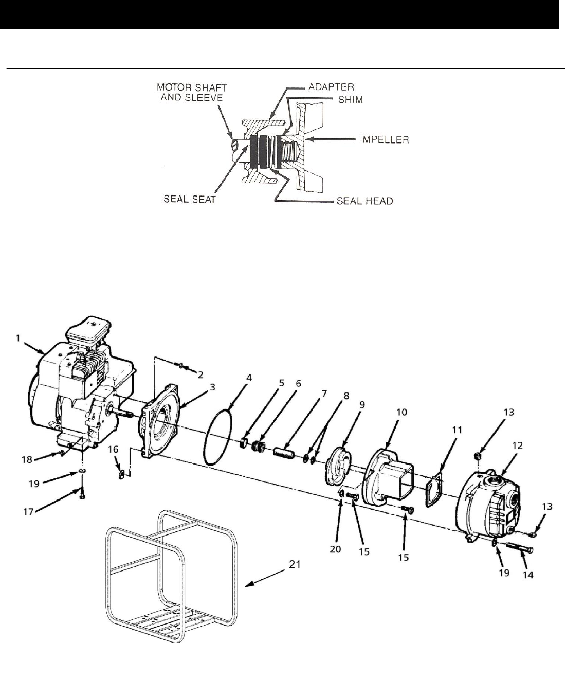
Refer to Figures 1 and 2
IMPORTANT: Always replace the seal seat (Ref. No. 5), seal head
(Ref. No. 6), and shaft sleeve (Ref. No. 7) to insure proper mating of
mechanical seal components.
1. Unthread cap screws (Ref. No. 14) and remove casing (Ref.
No. 12) and O-ring (Ref. No. 4) from the adapter (Ref. No.
3).
2. Unthread round head screws (Ref. No. 15) and remove
volute (Ref. No. 10) from adapter.
3. Unscrew impeller (Ref. No. 9) from the engine shaft.
Remove the impeller shim(s) (Ref. No. 8), shaft sleeve and
seal head from engine shaft.
NOTE: To keep the shaft from turning, remove the shroud from the
engine and hold the flywheel in place.
4. Unthread hex flange screw (Ref. No. 2) and remove the
adapter from the engine mounting face.
5. Push seal seat from the adapter recess with a screwdriver.
6. Clean the adapter recess before inserting a new seal seat.
7. Carefully wipe the ceramic surface of the new seal seat with
a clean cloth.
8. Wet the outside of the rubber portion of the seal seat with a
light coating of soapy water.
9. Press the new seal seat squarely into the cavity in the
adapter. Use finger pressure only to avoid scratching the
seal seat (This is a lapped surface and must be handled very
carefully).
10. After the seal seat is in place, insure that it is clean and has
not been marred.
11. Using a clean cloth, wipe the shaft and make certain that it is
perfectly clean.
12. Secure the adapter on the engine mounting face.
Tighten hex flange screws EVENLY to avoid cocking rabbet on
engine mounting face.
13. Apply a light coating of soapy water to the inside rubber
portion of seal head and slide onto the shaft sleeve. Slip the
shaft sleeve with seal head onto the engine shaft with the
black carbon face toward the white ceramic seal seat.
Do not touch or wipe the face of the Polished surface part of the
seal head.
14. Replace any impeller shim(s) removed in disassembly.
15. Screw impeller back in place, tightening until it is against the
shaft sleeve.
16. Remount volute and position O-ring in place.
IMPORTANT: Always inspect O-ring. Replace when cracked or worn.
Wet O-ring with soapy water for ease of assembly.
17. Remount casing.
SHIM ADJUSTMENT
1. When installing a replacement engine, adapter, impeller,
shaft sleeve, volute or casing it may be necessary to vary
the number of impeller shims (Ref. No. 8) that will be
required. This is easily done by adding one shim more than
was removed and reassembling the pump as described in
MECHANICAL SEAL REPLACEMENT section.
NOTE: When adding or removing shims, it is best to proceed with a
0.010" increment each time. Remove spark plug wire from engine and
ground. While tightening the unit together, turn the shaft (by pulling on
the recoil starter etc.); feel for the shaft seizing. If shaft begins to seize
before the fasteners are completely tight, disassemble the pump and
remove one shim and repeat assembly.
2. Once having added one shim more than original, ensure that
the volute (Ref. No. 10) and adapter (Ref. No. 3) are firmly
fitted (check fasteners, Ref. Nos. 2 & 15). When engine
turns freely, add shims until it does strike, then remove a
0.010" shim. This should allow the proper clearance.
3. Proper running clearance for the impeller should be as close
as possible to volute without striking; maximum clearance is
1/32" (0.032").
4. Follow the above procedure until proper clearance is
obtained. This will insure maximum performance.
[Type text]
3930-252-00
2
09/2012
Specifications Information and Repair Parts Manual 3163-95,316T-95,316H-95, 3930-95, 3932-95, 3930-D5
x
1 ½ & 2-Inch Trash Pumps
For Repair Parts contact dealer where pump was purchased.
Please provide following information:
-Model Number
-Serial Number (if any)
Part description and number as shown in parts list
Figure 2 – Repair Parts Illustration
Figure 1- Mechanical Seal Replacement

[Type text]
3930-252-00
3
09/2012
Specifications Information and Repair Parts Manual 3163-95,316T-95,316H-95, 3930-95, 3932-95, 3930-D5
x
Repair Parts List
Part Number for Models:
3930-D5
Ref.
3163-95
3930-95
No.
Description
316H-95
3932-95
316T-95
Qty.
1
Engine B&S 550 (3163-95, 316T-95)
1630-008-00
1630-008-00
1
Engine B&S 1350 (3930-95)
1639-034-00
1
Engine Honda GX160 (3932-95)
1639-036-00
1
Engine Honda GX120 (316H-95)
1630-005-00
1
Engine Hatz Diesel (3930-D5)
1630-020-90
1
2
Hex Head Cap Screw
*
*
*
4
3
Adapter
1608-005-00
2182-010-01
1608-005-00
1
4
O-Ring - Viton
Incl. w/Ref. KIT
Incl. w/Ref. KIT
Incl. w/Ref. KIT
1
5 & 6
Shaft Seal Assembly - Silicon Carbide/Viton
1641-166-91
1641-166-91
1641-166-91
1
7
Shaft Sleeve
1483-140-09
1483-140-09
1483-140-09
1
8
Impeller Shim Package
1658-000-90
1658-000-90
1658-000-90
1
9
Impeller
3163-010-09
3935-012-01
3163-010-09
1
10
Volute
3163-150-09
2182-002-01
3163-150-09
1
11
Flapper Valve - Viton
Incl. w/Ref. KIT
Incl. w/Ref. KIT
Incl. w/Ref. KIT
1
12
Casing
2111-001-02
2112-001-02
2111-001-01
1
13
1/2" NPT Plug
*
*
*
2
14
Hex Head Cap Screw
*
*
*
4
15
Socket Head Screw SS
1705-000-00
1705-000-00
1705-000-00
2
16
Nut
*
*
*
4
17
Hex Head Cap Screw
*
*
*
4
18
Hex Nut
*
*
*
4
19
Flat Washer
*
*
*
4
20
Lock Washer SS
1787-000-00
1787-000-00
1787-000-00
2
21
Roll Cage Frame Assembly
3120-105-K0
3120-105-K0
3120-105-K0
1
KIT
Flapper Valve/O-Ring Kit - Viton
3163-301-90
3540-301-90
3163-301-90
1
Raising Block
-
3120-119-90
-
2
NPT Pipe Nipple Kit
C366-90
C366-90
C366-90
1
NPT Suction Strainer
C362-90
C362-90
C362-90
1
2” NPT Street Elbow
1695-070-00
1695-070-00
-
1
Wheel Kit (optional)
A374-90
A374-90
A374-90
1
(*)
Standard Hardware Item, Available Locally
()
Seal assembly available as set only (includes seal head and seat).
()
Not Shown