537165 3 Amt 1 Inch Self Priming Centrifugal Pump Repair Parts User Manual
537163 3 Amt 1-Inch Self-Priming Centrifugal Pump Repair Parts 537163_3_AMT 1-Inch Self-Priming Centrifugal Pump Repair Parts
537171 3 Amt 1-Inch Self-Priming Centrifugal Pump Repair Parts 537171_3_AMT 1-Inch Self-Priming Centrifugal Pump Repair Parts
537168 3 Amt 1-Inch Self-Priming Centrifugal Pump Repair Parts 537168_3_AMT 1-Inch Self-Priming Centrifugal Pump Repair Parts
537166 3 Amt 1-Inch Self-Priming Centrifugal Pump Repair Parts 537166_3_AMT 1-Inch Self-Priming Centrifugal Pump Repair Parts
537170 3 Amt 1-Inch Self-Priming Centrifugal Pump Repair Parts 537170_3_AMT 1-Inch Self-Priming Centrifugal Pump Repair Parts
User Manual: Pump 537165 3 Amt 1-Inch Self-Priming Centrifugal Pump Repair Parts
Open the PDF directly: View PDF ![]() .
.
Page Count: 4
Specications Information and Repair Parts Manual 4294-98 thru 429N-98
4294-251-00 1 8/2013
Please read and save this Repair Parts Manual. Read this manual and the General Operating Instructions carefully before attempting to assemble, install, operate
or maintain the product described. Protect yourself and others by observing all safety information. The Safety Instructions are contained in the General Operating
Instructions. Failure to comply with the safety instructions accompanying this product could result in personal injury and/or property damage! Retain instructions
for future reference. AMT reserves the right to discontinue any model or change specications at any time without incurring any obligation.
©2013 American Machine & Tool Co., Inc. of PA, A Subsidiary of The Gorman-Rupp Company, All Rights Reserved.
Periodic maintenance and inspection is required on all pumps to ensure proper operation. Unit must be clear of debris and sediment. Inspect for leaks and loose bolts. Failure to do so
voids warranty.
1-Inch Self-Priming Centrifugal Pumps
Refer to pump manual 1808-634-00 for General Operating and Safety Instructions.
MAINTENANCE
Make certain that power source is disconnected before attempting to
service or disassemble any components! If power disconnect is out-of-
sight, lock it in open position and tag it to prevent application of power.
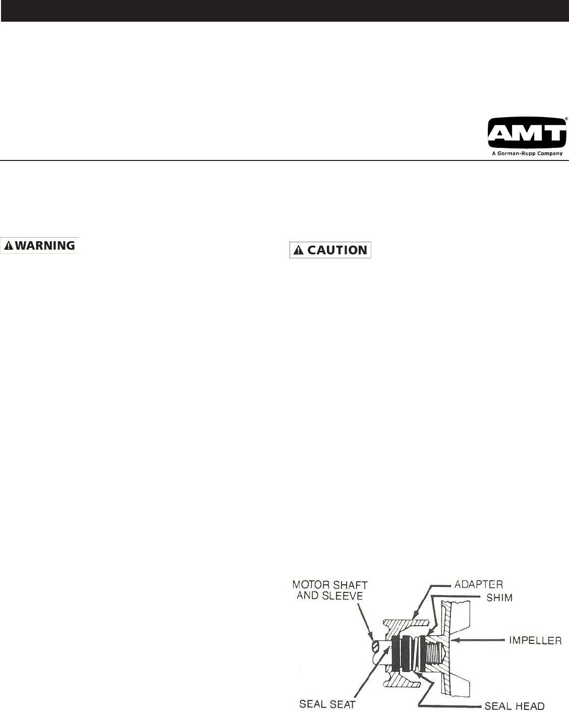
MECHANICAL SEAL REPLACEMENT
Refer to Figures 1 and 2.
IMPORTANT: Always replace both seal seat and seal head to ensure proper
mating of mechanical seal components!
NOTE: It is not necessary to remove piping from pump casing. The motor and
impeller assembly are removed from back of casing.
1. Drain pump before disassembling. Unscrew pipe plug (Ref. No. 13) to
drain most of liquid; some will be left in bottom.
2. Unthread hex nuts (Ref. No. 4) and remove pump casing (Ref. No. 12)
and o-ring (Ref. No. 7) from casing cover (Ref. No. 6).
3. To unscrew impeller (Ref. No. 11), turn counterclockwise (CCW) facing
impeller. Unscrew acorn nut (Ref. No. 16) and o-ring gasket (Ref. No. 15)
before unscrewing impeller.
NOTE: A screwdriver slot or two ats for use with an open end 7/16” wrench
are provided at rear of motor shaft (remove bearing cap for access). To hold
motor shaft from turning, either insert a large screwdriver blade into the slot, or
use a 7/16” wrench across the ats.
4. Unthread cap screws (Ref. No. 5) and remove motor adapter (Ref. No. 3).
Seal head (Ref. No. 9) and impeller shims (Ref. No. 10) will come loose
at this time. NOTE: Casing cover will still be attached to motor adapter.
IMPORTANT: Retain impeller shims for use when reassembling unit.
5. Push seal seat (Ref. No. 8) from casing cover with screwdriver.
6. Clean adapter recess before inserting a new seal seat.
7. Carefully wipe polished surface of new seal seat with a clean cloth.
8. Wet outside of rubber portion of seal seat with a light coating of soapy
water.
9. Press new seal seat squarely into cavity in casing cover. If seal seat does
not press squarely into cavity, it can be adjusted into place by pushing on
it carefully with a piece of pipe or dowel. Always use a piece of cardboard
between pipe and seal seat to avoid scratching seal seat. (This is a
lapped surface and must be handled very carefully).
10. After seal seat is in place, be sure that it is clean and has not been marred.
11. Using a clean cloth, wipe shaft and make certain that it is perfectly clean.
12. Carefully guide motor shaft through seal seat. Secure motor adapter on
motor mounting face.
13. Apply a light coating of soapy water to inside rubber portion of seal head
and slide onto shaft (with sealing face rst) so that rubber portion is just
up over shaft shoulder.
Do not touch or wipe face of polished part of the seal head.
14. Replace any impeller shims which may have been removed in dis-
assembly (see “Shim Adjustment”).
15. Screw impeller back in place, tightening until it is against shaft shoulder.
Replace o-ring gasket and acorn nut.
16. Remount o-ring and pump casing on casing cover.
IMPORTANT: Always inspect o-ring gasket for cracks or cuts when unit is
disassembled. Replace if damaged.
SHIM ADJUSTMENT
When installing a replacement impeller (Ref. No. 11) or motor (Ref. No. 1), it
may be necessary to adjust number of shims (Ref. No. 10) to ensure proper
running clearance between impeller and casing. Proceed as follows:
NOTE: A proper running clearance is less than 0.010.
1. For impeller replacement, add one 0.010” shim in addition to shims
removed originally.
2. For motor replacement, add two 0.010” shims in addition to shims removed
during disassembly.
3. Reassemble pump using “Mechanical Seal Replacement” for reference.
IMPORTANT: Be sure that casing is in place and check shaft to make sure it is
turning freely (use screwdriver slot or two ats at rear of motor to turn shaft). If
it turns freely, check to ensure that casing cover and casing are tted metal-to-
metal where they meet on outside. If they are not metal-to-metal, tighten the hex
nuts (Ref. No. 4) and recheck shaft for free turning. Tighten, carefully turning
shaft while tightening so that motor bearings are not damaged in event that too
many shims were installed. If shaft seizes before fasteners are completely tight,
disassemble pump and remove one shim and repeat reassembly.
DESCRIPTION
These stainless steel with Viton seal pumps are self-priming (to 6 ft. lift) units designed for transferring perchlorethylene and other non-ammable liquid chemicals.
Handle liquids from 40º F to 180º F (4º C to 82º C). Units should be used only with non-abrasive, non-ammable liquids that are compatible with pump component
materials.
Figure 1 - Mechanical Seal Replacement
Specications Information and Repair Parts Manual 4294-98 thru 429N-98
4294-251-00 2 8/2013
For Repair Parts contact dealer where pump was purchased.
Please provide following information:
-Model Number
-Serial Number (if any)
Part description and number as shown in parts list
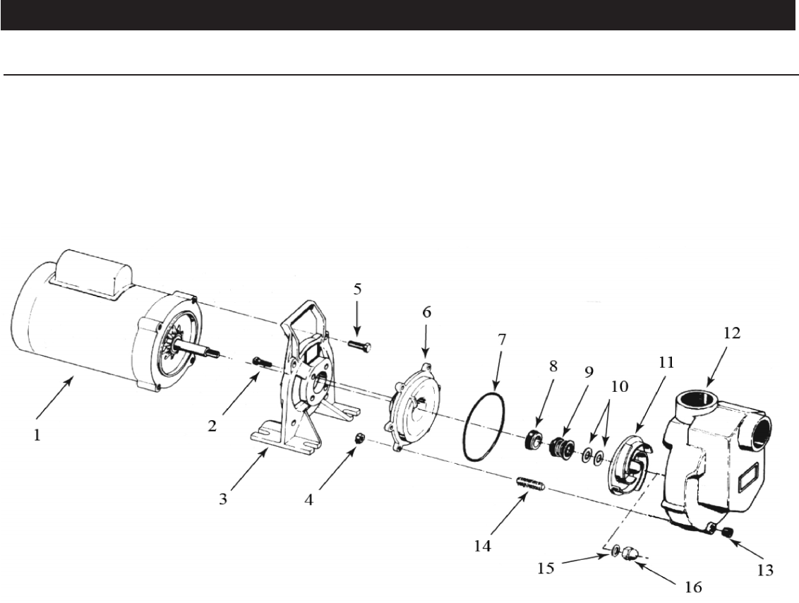
Figure 2 - Repair Parts Illustrations
1-Inch Self-Priming Centrifugal Pumps

Specications Information and Repair Parts Manual 4294-98 thru 429N-98
4294-251-00 3 8/2013
Part Number for Models
4294-98 (1/3 HP) 4295-98 (1/2 HP) 4296-98 (3/4 HP) 4297-98 (1 HP) 4298-98 (1.5 HP)
-- 429F-98 (1/2 HP) 429G-98 (3/4 HP) 429H-98 (1 HP) 429J-98 (1.5 HP)
Ref 429A-98 (1/2 HP) 429B-98 (3/4 HP) 429C-98 (1 HP) 429D-98 (1.5 HP) 429E-98 (2 HP)
No. Description -- 429K-98 (3/4 HP) 429L-98 (1 HP) 429M-98 (1.5 HP) 429N-98 (2 HP) Qty
1 Motor - 1 Phase ODP 1626-008-00 1626-009-00 1626-010-00 1626-011-00 1626-012-00 1
Motor - 3 Phase ODP -- Discontinued Discontinued Discontinued Discontinued 1
Motor - 1 Phase TEFC 1626-301-00 1626-302-00 1626-303-00 1626-304-00 1626-305-00 1
Motor - 3 Phase TEFC -- 1626-308-00 1626-309-00 1626-310-00 1626-311-00 1
2 Fastener * * * * * 4
3 Adapter 4294-030-09 4294-030-09 4294-030-09 4294-030-09 4294-030-09 1
4 Fastener * * * * * 6
5 Fastener * * * * * 4
6 Casing Cover 4294-020-01 4294-020-01 4294-020-01 4294-020-01 4294-020-01 1
7 Casing O-Ring - Viton Incl. w/Ref. KIT Incl. w/Ref. KIT Incl. w/Ref. KIT Incl. w/Ref. KIT Incl. w/Ref. KIT 1
8 & 9 Shaft Seal Assembly - Viton 1640-161-91 1640-161-91 1640-161-91 1640-161-91 1640-161-91 1
10 Impeller Shim Kit 1657-000-90 1657-000-90 1657-000-90 1657-000-90 1657-000-90 1
11 Impeller 4294-010-01 4295-010-08 4295-010-07 4295-010-06 4295-010-05 1
12 Casing 4294-001-01 4294-001-01 4294-001-01 4294-001-01 4294-001-01 1
13 Pipe Plug * * * * * 1
14 Fastener * * * * * 6
15 Impeller O-Ring - Viton Incl. w/Ref. KIT Incl. w/Ref. KIT Incl. w/Ref. KIT Incl. w/Ref. KIT Incl. w/Ref. KIT 1
16 Impeller Fastener 1784-001-00 1784-001-00 1784-001-00 1784-001-00 1784-001-00 1
KIT O-Ring Kit - Viton 4295-300-90 4295-300-90 4295-300-90 4295-300-90 4295-300-90 1
(includes Ref. Nos. 7 and 15)
(*) Standard hardware item, available locally.
Repair Parts List