537482 2 Zoeller Lawn Sprinkler Pump Installation Instructions 020293 Fm2101 User Manual
537482 2 Zoeller Lawn Sprinkler Pump Installation Instructions 537482_2_Zoeller Lawn Sprinkler Pump Installation instructions
537484 2 Zoeller Lawn Sprinkler Pump Installation Instructions 537484_2_Zoeller Lawn Sprinkler Pump Installation Instructions
537483 2 Zoeller Lawn Sprinkler Pump Installation Instructions 537483_2_Zoeller Lawn Sprinkler Pump Installation Instructions
537481 2 Zoeller Lawn Sprinkler Pump Installation Instructions 537481_2_Zoeller Lawn Sprinkler Pump Installation Instructions 537481_2_Zoeller Lawn Sprinkler Pump Installation Instructions pdf pumpproducts
537481 2 Zoeller Lawn Sprinkler Pump Installation Instructions 537481_2_Zoeller Lawn Sprinkler Pump Installation instructions 537481_2_Zoeller Lawn Sprinkler Pump Installation instructions pdf pumpproducts
User Manual: Pump 537482 2 Zoeller Lawn Sprinkler Pump Installation Instructions
Open the PDF directly: View PDF ![]() .
.
Page Count: 8
© Copyright 2003 Zoeller Co. All rights reserved.
1
1. Inspect all materials. Occasionally, products are damaged during shipment. If the unit is damaged, contact your dealer before using.
2. Carefully read all the literature provided to familiarize yourself with specifi c details regarding installation and use before attempting the
installation. These materials should be retained for future reference.
SECTION: 6.10.049
FM2101
0703
Supersedes
0603
INSTALLATION INSTRUCTIONS
330 Series Centrifugal, Lawn Sprinkler Pumps
Product information presented
here refl ects conditions at time
of publication. Consult factory
regarding discrepancies or
inconsistencies. MAIL TO: P.O. BOX 16347 • Louisville, KY 40256-0347
SHIP TO: 3649 Cane Run Road • Louisville, KY 40211-1961
(502) 778-2731 • 1 (800) 928-PUMP • FAX (502) 774-3624
visit our web site:
http://www.zoeller.com
PREINSTALLATION CHECKLIST - ALL INSTALLATIONS
1. To help reduce the risk of electrical shock, a proper ground
or control box of grounding type must be installed and protected
by a ground fault circuit interrupter (GFCI) in accordance with the
National Electrical Code and applicable local codes.
2. DO NOT USE AN EXTENSION CORD. Extension cords that are
too long or too light do not deliver suffi cient voltage to the pump
motor. But more important, they could present a safety hazard if
the insulation were to become damaged or the connection end were to fall
into a damp or wet area.
3. Make sure the pump’s electrical supply circuit is equipped with fuses
or circuit breakers of proper capacity. A separate branch circuit, sized
according to the National Electrical Code for the current shown on the pump
name plate is recommended.
4. TESTING FOR GROUND. As a safety measure, electrical supply
should be checked for ground using an Underwriters Laboratory
Listed circuit analyzer which will indicate if the power, neutral and
ground wires are correctly connected . If they are not, call a qualifi ed licensed
electrician.
5. Installation and checking of electrical circuits and hardware should
only be performed by a qualifi ed licensed
electrician.
6. FOR YOUR PROTECTION ALWAYS DISCONNECT PUMP FROM
ITS POWER SOURCE BEFORE HANDLING. De-energize the
circuit at the control box. If the power point is out-of-sight, lock it
in the open position and tag it to prevent unexpected application of power.
Failure to do so could result in fatal electrical shock.
7. Unit must be securely and adequately electrically grounded. This can be
accomplished by wiring the unit to a ground metal-clad raceway system or
by using a separate ground wire connected to the bare metal of the motor
frame or other suitable means.
8. Do not put a valve in the discharge line without automatic shut-off
capability. Failure to install an automatic shut-off (pressure switch
and tank) can allow the pump to run at no fl ow causing the pumped
liquid to overheat and cause steam burns.
9. Risk of electric shock. This pump has not been investigated for
use in swimming pool areas.
10. According to the state of California (Prop 65), this product contains chemicals
known to the state of California to cause cancer and birth defects or other
reproductive harm.
NOTE: Repair and service should be performed by an Authorized Service Station
only (Consult factory).
NOTE: Pumps are designed to have a maximum static lift (suction head) of 25
feet (vertical distance from water surface to center line of pump).
NOTE: Pumps with the CSA CUS mark are tested to UL standard UL 778 and
certifi ed to CSA standard C22.2 No. 108.
1. Check to be sure your power source is adequate to handle the
amperage requirements of the motor as indicated on the pump or
unit I.D. tag.
2. All plumbing (discharge and intake lines) must be installed to
meet local codes.
3. Be certain the pump is completely primed before starting. Otherwise
damage may occur to the seal.
4. Be careful when touching the exterior of an operating
motor - it may be hot enough to be painful or cause
injury. 020293
SEE BELOW FOR LIST OF CAUTIONS
Notice to Installer: Instructions must remain with installation.
SEE BELOW FOR LIST OF WARNINGS

© Copyright 2003 Zoeller Co. All rights reserved.
2
LOCATION
1. Pump can be located at the well or can be offset some distance
away from the well. For best performance it should be located as
close to the well as possible.
2. Location can be in the basement, a watertight pit below ground, or
in a pump house above ground.
3. Ventilation and drainage must be provided to prevent damage from
moisture to the motor and pressure switch.
4. The pump and all piping must be protected from freezing.
5. Pump and pipe line must be drained when not in use if there is any
danger of freezing.
WELL CONDITIONS
1. Wells should be pumped clean of all sand and foreign matter
before installing the pump or damage may result to the operating
parts.
2. The well must be able of supplying enough water to satisfy the
capacity of the pump and water needs. The water level must not
draw down below the maximum rated suction lift of the pump or
loss of capacity and prime will result.
SUCTION LIMITATIONS
1. Shallow well installation is satisfactory where the suction lift is less
than 25 feet. Suction lift is the vertical lift plus losses due to friction
2. Suction lift varies depending upon elevation (altitude) and water
temperature.
PIPING
1. Plastic or galvanized steel pipe may be used in the installation.
Plastic pipe must have a minimum pressure rating 160 P.S.I. Gal-
vanized steel pipe must be in good condition free of rust and scale.
Threads should be sharp and cleanly cut.
2. Both the suction and discharge pipe should be no smaller than the
corresponding tappings of the pump (See Figure 1). If long runs
are encountered larger pipe should be used. Smaller pipe will
reduce the capacity of the pump.
3. All joints and connections should have pipe sealing compound
(male threads only) applied and drawn up tightly.
The entire system must be air and water tight for efficient operation.
PUMP INSTALLATION
1. Refer to Figures 3, 4, 5, and 6 for typical installations. If galva-
nized pipe is used, both the suction and discharge pipe should be
supported at a point near the pump to avoid strains being placed
on the pump.
2. The suction pipe should slope upwards from the water source
to the pump. Locate the pump as close to the water as possible
keeping the suction pipe as short as conditions permit.
3 Avoid dips or pockets in offset piping or air will accumulate at high
points which will make priming difficult.
4. A foot valve located in the water or a check valve located as close
to the water as possible will reduce priming time of the pump and
help maintain prime. A strainer must be used on the suction line to
filter out dirt and debris.
5. Install a gate valve and union in the discharge line. For removal
of the pump for service, close the gate valve and disconnect the
union.
Do not use a globe valve or other restricting type
of valve at the discharge. This will seriously restrict the capacity of the
pump.
LIMITED WARRANTY
Zoeller Pump Company warrants, to the purchaser and subsequent owner
during the warranty period, every new Zoeller Pump Company product to
be free from defects in material and workmanship under normal use and
service, when properly installed, used and maintained, for 1) Standard
Warranty - a period of one year from date of installation or 18 months
from date of manufacturer, whichever comes fi rst OR 2) Optional Three
(3) Year Warranty - a period of three (3) years from date of installation or
42 months from date of manufacturer whichever comes fi rst. Parts that
fail, (within standard or three (3) year optional warranty) that inspections
determine to be defective in material or workmanship, will be repaired,
replaced or remanufactured at Zoeller Pump Company’s option, provided
however, that by so doing we will not be obligated to replace an entire
assembly, the entire mechanism or the complete unit. No allowance will
be made for shipping charges, damages, labor or other charges that may
occur due to product failure, repair or replacement.
This warranty does not apply to any material that has been disassembled
without prior approval of Zoeller Pump Company, subjected to misuse,
misapplication, neglect, alteration, accident or act of God; that has not
been installed, operated or maintained in accordance with Zoeller Pump
Company installation instructions; that has been exposed to but not
limited to the following: sand, gravel, cement, mud, tar, hydrocarbons
or hydrocarbon derivatives (oil, gasoline, solvents, etc), wash towels or
feminine sanitary products, etc. or other abrasive or corrosive substances.
This warranty is in lieu of all other warranties expressed or implied; and
we do not authorize any representative or other person to assume for
us any other liability in connection with our products.
Contact Zoeller Pump Company, 3649 Cane Run Road, Louisville, Ken-
tucky 40211-1961, Attention: Customer Service Department to obtain
any needed repair or replacement of part(s) or additional information
pertaining to our warranty.
ZOELLER PUMP COMPANY EXPRESSLY DISCLAIMS LIABILITY
FOR SPECIAL, CONSEQUENTIAL OR INCIDENTAL DAMAGES
OR BREACH OF EXPRESSED OR IMPLIED WARRANTY; AND ANY
IMPLIED WARRANTY OF FITNESS FOR A PARTICULAR PURPOSE
AND OF MERCHANTABILITY SHALL BE LIMITED TO THE DURATION
OF THE EXPRESSED WARRANTY.
Some states do not allow limitations on the duration of an implied war-
ranty, so the above limitation may not apply to you. Some states do not
allow the exclusion or limitation of incidental or consequential damages,
so the above limitation or exclusion may not apply to you.
This warranty gives you specifi c legal rights and you may also have
other rights which vary from state to state.
© Copyright 2003 Zoeller Co. All rights reserved.
3
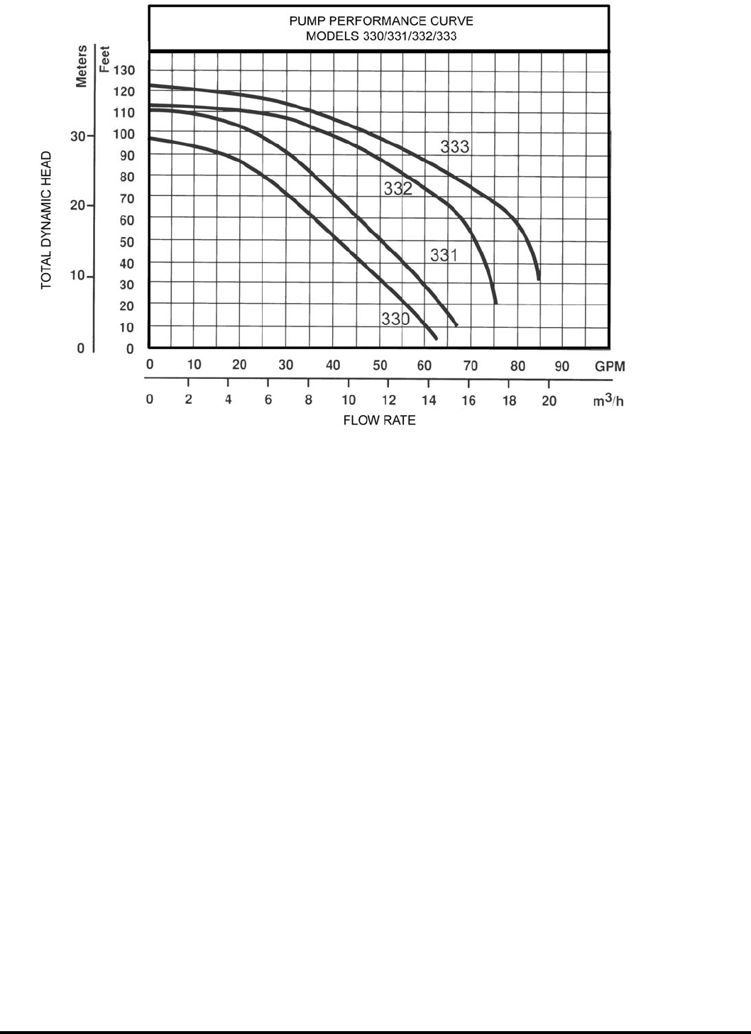
PUMP PERFORMANCE Capacity U.S. Gallons Per Minute Figure 1
Model HP Suction
Lift Feet
Discharge Pressure (PSI) Shut off
Pressure PSI
Suction
Pipe Tap
Discharge
Pipe Tap
10 15 20 25 30 35 40 45
330-0005 3/4
5 564842372921 41
2” 1-1/2”15 47 42 37 29 22 12 37
25 43 37 31 22 10 33
331-0005 1
5 5853484338322311 48
2” 1-1/2”15 53 48 45 37 31 24 12 43
25 48 44 38 33 25 14 39
332-0005 1-1/2
5 7877747062534330 47
2” 1-1/2”15 70 68 66 62 53 43 30 41
25 47 46 45 44 42 34 36
333-0005 2
5 8684817771625240 50
2” 1-1/2”15 76 74 72 69 64 55 43 25 45
25 52 51 50 47 45 42 30 40
SPECIFICATIONS Figure 2
HP Type Volts/
Amps Hz RPM
Motor Voltage
(Factory)
Connected
Service Factor
Motor Amps Max
Liquid
Temp
Max
Suction
Lift
Single Phase
115V 230V
3/4
Single Ph 115/230 60 3450
115V 14.0 7.0
180°F 25 ft.
1
230V
18.0 9.0
1-1/2 21.0 10.5
2 25.0 12.5
Suction lift varies, depending upon elevation (altitude) and water temperatures.
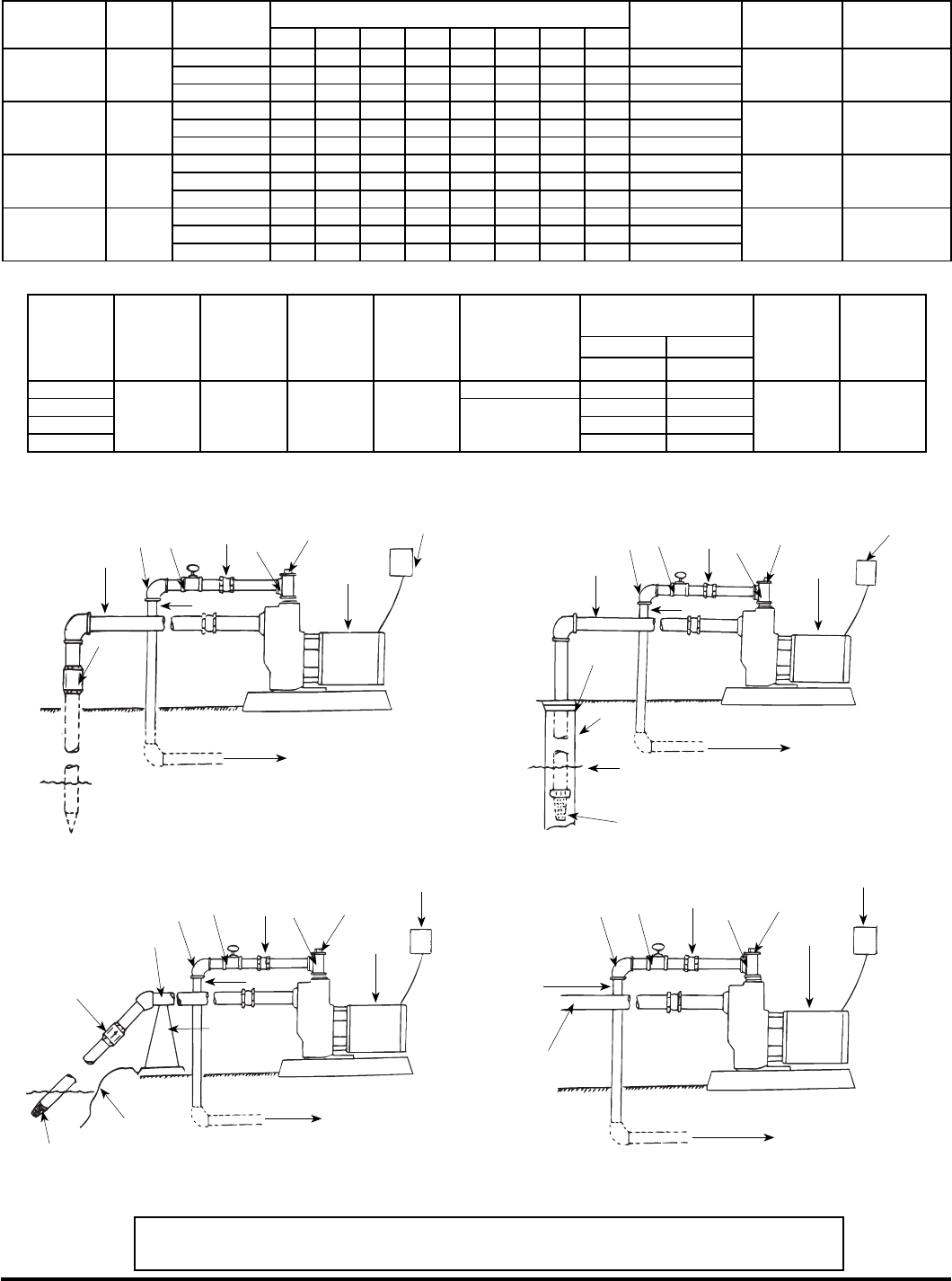
TYPICAL INSTALLATIONS
IL0176
IL0177
Figure 3 — From Ground Water “Drive Point” Figure 4 — From Ground Water “Well”
1
2
3 4 567
8
9
1
2
34567
8
9
Check
Valve
To Sprinkler System
Water Level
Drive Point
Well Seal
To Sprinkler System
Foot Valve With Screen
Well
Water Level
Figure 6 — From City Water Main
IL0179
1
2
345
67
8
9
To Sprinkler System
Figure 5 — From Surface Water “Lake, Stream, Cistern or
Canal”
IL0178
1
2
34567
8
9
Pipe Support
Check Valve
Water Level
Strainer
To Sprinkler System
1 — Suction Pipe 2 — Discharge Pipe 3 — Elbow 4 — Gate Valve 5 — Union
6 — Discharge Tee 7 — Priming Plug 8 — Pump 9 — Fuse Box
© Copyright 2003 Zoeller Co. All rights reserved.
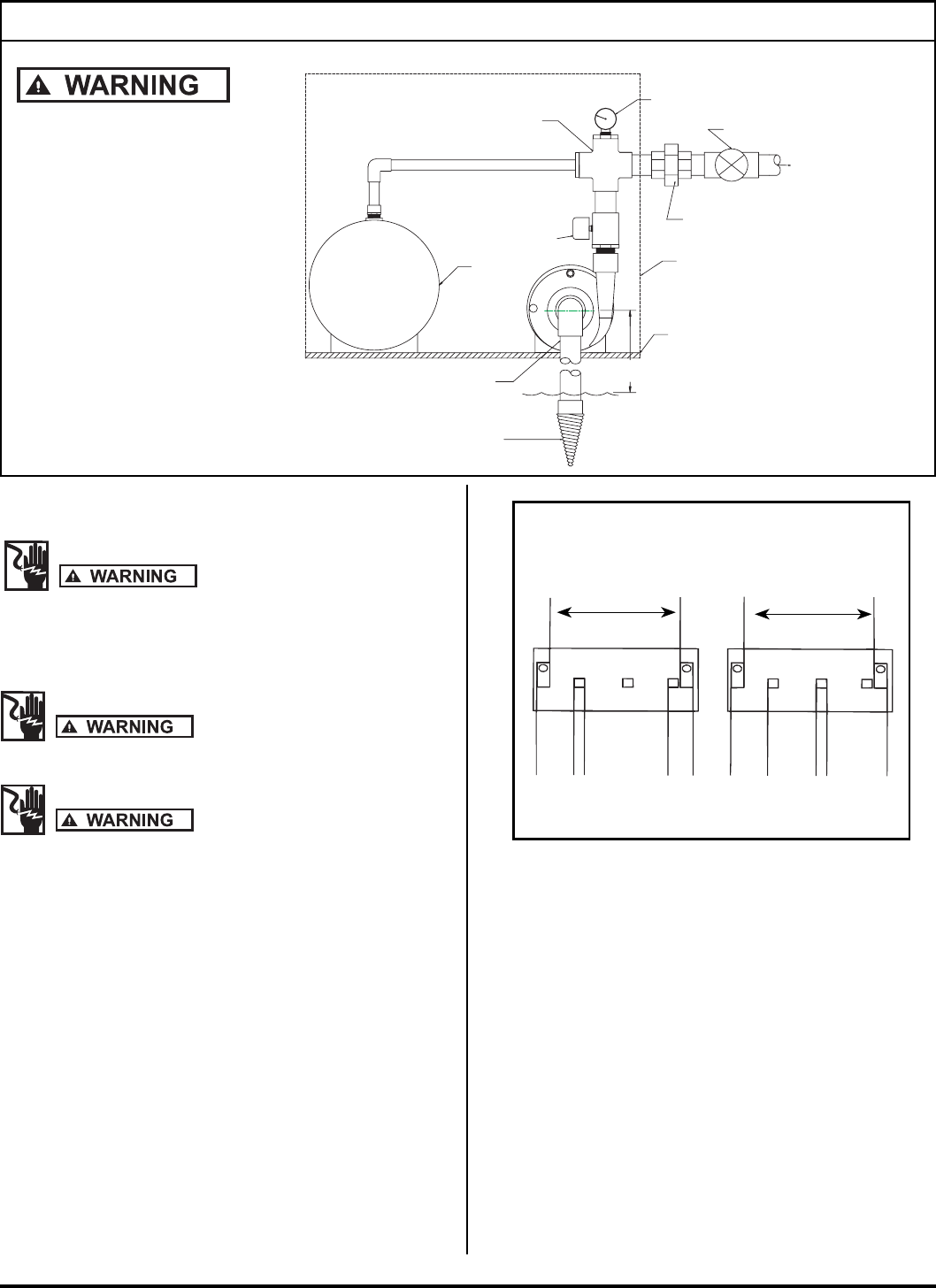
4
PRESSURE GUAGE
UNION
TO APPLICATION
SOLID, LEVEL
FOUNDATION
CROSS
SHUT OFF VALVE
RESERVOIR
CENTERLINE OF
WATER SOURCE.
SURFACE OF
VERTICAL LIFT
(25' MAX)
PUMP INTAKE.
FOOT VALVE
INTAKE (SUCTION) PIPING
1 1/2" MINIMUM
PRESSURE SWITCH
WEATHER TIGHT ENCLOSURE
0
10
20
30 40
50
60
70
A pressure switch must be
used to provide automatic
shut-off when the pump is
operating unattended,
use the following
illustration as a guideline
for installing a pressure
tank and pressure switch.
Automatic Shut-Off
SK1981
IL0180
L1 ABL2 L1 ABL2
115 VOLTS
SINGLE PHASE
230 VOLTS
SINGLE PHASE
LINE LINE
T
A
N
R
E
D
Y
E
L
L
O
W
W
H
I
T
E
G
R
A
Y
Y
E
L
L
O
W
W
H
I
T
E
G
R
A
Y
T
A
N
R
E
D
DO NOT CONNECT ANY GROUND WIRE TO THESE LEADS
Figure 7 - Wiring Diagram for Single Phase 3/4 - 2 HP
CHECK VOLTAGE OF POWER
SOURCE BEFORE CONNECTING
ELECTRICAL CONNECTIONS
GROUNDING
To reduce the risk of electric shock the
motor must be securely and adequately grounded to a grounded metal
raceway system, or by using a separate grounding wire connected to
bare metal on the motor frame, or to the grounding screw located inside
motor terminal box, or other suitable means. Refer to National Electric
Code (NEC Article 250 {Grounding}) for additional information.)
All wiring should be performed by a
qualified electrician and in accordance with the national electric code
and local electric codes.
Failure to connect the motor frame to
equipment grounding conductor by using green screw may result in seri-
ous electrical shock.
WIRING CONNECTIONS
1. This unit is not water proof and is not intended to be used in
showers, saunas, or other potentially wet locations. The motor
is designed to be used in a clean dry location with access to an
adequate supply of cooling air. Ambient temperature around the
motor should not exceed 104F (40C). For outdoor installations
motor must be protected by a cover that does not block airflow to
and around the motor. This unit is not weatherproof nor is it able to
be submersed in water, or any other liquid.
2. Single phase motors, 3/4 - 2 HP, are dual voltage and can be con-
nected for 115V or 230V service.
3. If the motor wiring must be changed to conform to your specific
voltage requirements then the motor should be rewired. For proper
electrical connections, refer to the connection diagram located on
the nameplate of the motor or the one in Figure 7. Make sure con-
nections are correct for the voltage being supplied to the motor.
MOTOR PROTECTION
1. All motors have built-in thermal protection for all voltages. The
overload protects the motor against burnout from overload of low
voltage, high voltage and other causes. The device is automatic
and resets itself once the temperature has dropped to a safe point.
Frequent tripping of the device indicates trouble in the motor or
power lines and immediate attention is needed. The device should
never be tampered with unless the trouble is located and cor-
rected.
2. Undersize wiring can cause motor failure (low voltage), frequent
cut-out of motor overload protector, television interference and
even fire. Make certain the wiring is adequately sized (Figure
9), well insulated and connected to a separate circuit outside the
house in case of fire.
© Copyright 2003 Zoeller Co. All rights reserved.
5
ROTARY SEAL ASSEMBLY REPLACEMENT
Make certain that the power supply is
disconnected before attempting to service the unit!
The rotary seal assembly must be handled carefully
to avoid damaging the precision lapped faces of the sealing components.
See Parts List For Reference Numbers
1. Disengage pump body (Ref. No. 10) from motor and mounting ring
(Ref. No. 2) by removing bolts (Ref. No. 11).
2. Remove diffuser bolts (Ref. No. 8) and remove diffuser (Ref. No.
7).
3. Unthread impeller (Ref. No. 6). from motor shaft.
NOTE: To remove the impeller use a 9/16" open end wrench to hold the
motor shaft. The shaft flat area is located in the middle of the mounting
ring.
4. The rotary seal (Ref. No. 5) will come loose at this time. Use a screw-
driver (or similar instrument) to pry the ceramic seal and rubber gasket
from the recess of the mounting bracket.
Be careful not to damage the motor shaft or recess
surface.
5. Clean the recess and motor shaft thoroughly.
6. Install the new rotary seal assembly:
a. Insert the ceramic seal and the rubber gasket into the recess.
NOTE: To help facilitate installation, apply a light coating of oil to the
outside diameter of the rubber gasket. Make certain that the ceramic
seal is kept clean and free of dirt and/or oil.
b. Slip the remaining parts of the rotary seal assembly onto the
motor shaft.
7. Replace the impeller and diffuser removed in Step B and C.
8. Reassemble the pump body to the motor and mounting bracket.
MOTOR REPLACEMENT
1. NEMA J motors can be replaced in the field with any standard
NEMA J jet pump motor by referring to the following instructions
and the attached parts list.
2. Follow steps A-D as outlined under rotary seal replacement to
remove the pump body, diffuser, impeller and rotary seal.
3. Remove bolts (Ref. No. 3) that connect the motor (Ref. No.1) to
the mounting ring (Ref. No. 2) and pull motor away.
4. Replace motor with standard NEMA J jet pump motor by position-
ing motor against the mounting frame and assembling with four
3/8" x 3/4" cap screws. The mounting base is connected at the
bottom of the mounting frame with two 3/8" x 1/2" cap screws.
5. Follow steps E,F,G & H of Rotary Seal Assembly to reassemble the
remainder of the pump.
NOTE: Because damage to the shaft seal is most likely to occur in
disassembly, a new seal is required.
MOTOR DATA Figure 8
HP Phase Volts Code
Letter
Max.
Amps
Locked
Rotor Amps
3/4
3/4
1
1
115
230
K
K
14.00
7.00
52.0
26.0
1
1
1
1
115
230
L
L
18.00
9.00
70.0
39.0
1-1/2
1-1/2
1
1
115
230
J
J
21.00
10.50
98.0
49.0
2
2
1
1
115
230
H
H
25.00
12.50
116.0
58.0
OPERATION
1. When installation has been completed remove the priming plug
from the discharge tee (see Figures 3-6) and fill the pump body
and suction pipe completely with water. No additional water will be
needed for subsequent start-ups unless the pump body is drained.
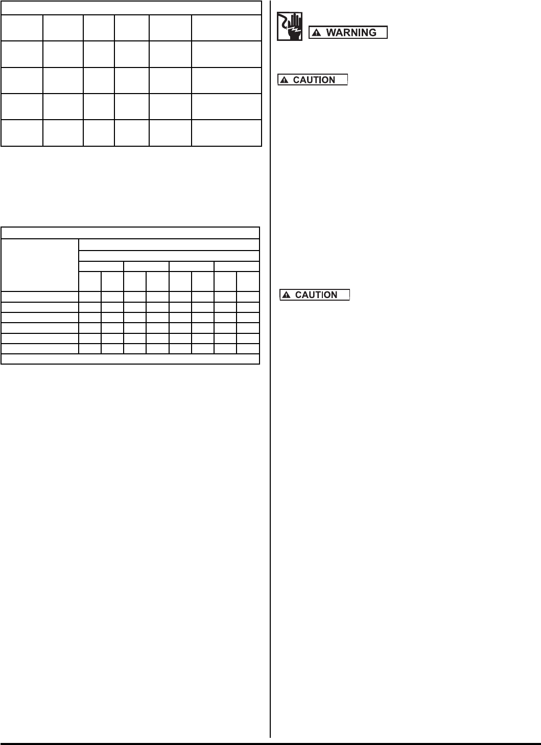
WIRE SIZE CHART Figure 9
Distance From
Motor To Fuse
Box, Meter or
Electrical Outlet
Minimum Copper Wire Size Chart (Gauge)
Single Phase Motors
3/4 HP 1 HP 1-1/2 HP 2 HP
115
Volt
230
Volt
115
Volt
230
Volt
115
Volt
230
Volt
115
Volt
230
Volt
0-50 Ft. 12 14 10 14 10 12 10 12
50-100 Ft. 12 14 10 14 8 12 8 12
100-150 Ft. 10 14 10 12 6 12 6 12
150-200 Ft. 10 12 8 12 * 10 * 10
200-300 Ft. 8 12 6 10 * 10 * 10
Fuse Size (Amps) 20 15 30 15 30 20 30 20
(*) Not economical to run in 115V, use 230V
2. After the pump is turned on it will require 2-5 minutes before all
air is evacuated from the suction line and water begins to flow. If
there is no water after 10 minutes turn the pump off and check the
following.
a. Any air leaks on the suction line must be eliminated.
b. Suction pipe inlet should be a minimum of 5 feet below the water
level.
c. Total suction lift cannot be greater than 25 feet.
d. Any restrictions in the discharge line, such as a closed valve
must be eliminated.
NOTE: Unit must be full of liquid before operating. Never run dry,
or against a closed discharge. Dry running or running unit against a
closed discharge will cause damage to the shaft seal. Do not pump
dirty water or abrasive liquids, otherwise the same may occur as if
running dry.
MOTOR ROTATION
Pumps are designed to rotate in one direction only, (counterclockwise
when facing the pump suction tapping) and cannot be reversed.
MAINTENANCE
Lubrication
The pumps and motors require no lubrication. The ball bearings of
the motor have been greased at the factory. Under normal operating
conditions they should require no further greasing.
Freezing
Drain the entire system if there is danger of freezing. A drain plug is
provided at the bottom of the pump case for this purpose.
© Copyright 2003 Zoeller Co. All rights reserved.
6
© Copyright 2003 Zoeller Co. All rights reserved.
7
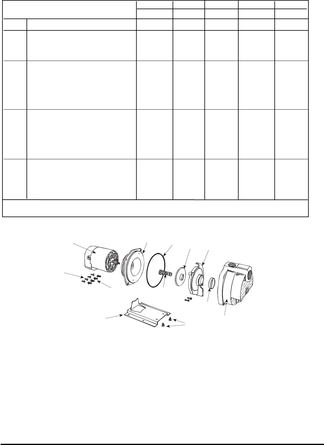
MODEL 330-0006 331-0006 332-0006 333-0006
HP 3/4 1 1-1/2 2
ITEM DESCRIPTION PART NO. QTY.
1 Motor, Nema J - 1 PH 94J107 94J110 94J115 94J120
Motor Access Cover 136132R 1 1 1 1
▲ Screws, Access Cover 136133 2 2 2 2
▲ Slinger, Washer 126905 1 1 1 1
2 Mounting Ring 020292 1 1 1 1
3 Hex Hd. Cap Screws 3/8” x 3/4” * 4 4 4 4
4 Ring, Square Cut 133261 1 1 1 1
5 Seal, Rotary w/Spring 131100 1 1 1 1
6 Impeller, Plastic “P” Models 133646 135620 134794 ----
6 Impeller, Brass “B” Models ---- ---- ---- 133255
7 Diffuser 136469 1 1 1 1
8 Hex Hd. Cap Screws 1/4 x 1” * 2 2 2 2
9 Rubber Diffuser 133260 1 1 1 1
10 Pump Body 020291 1 1 1 1
11 Hex Hd. Cap Screws 7/16 x 1” * 4 4 4 4
12 Base 134217 1 1 1 1
13 Hex Hd. Cap Screws 3/8 x 1/2” * 2 2 2 2
(*) Standard Hardware Item (▲) Not Shown
IL0174
SELF-PRIMER PUMP REPAIR PARTS — 330 SERIES
1
2
3
11
12
13
4
5
67
89
10

© Copyright 2003 Zoeller Co. All rights reserved.
8
Sympton Possible Cause(s) Corrective Action
Little or no discharge 1. Casing not initially filled with water 1. Fill pump casing
2. Total head too high 2. Shorten suction lift and/or discharge head
3. Suction lift too high, or too long 3. Lower suction lift, install foot valve and prime,
or shorten length of suction line
4. Impeller clogged 4. Clean
5. Hole or air leak in suction line 5. Repair or replace; do not use Teflon tape;
use pipe sealing compound
6. Foot valve too small 7. Match foot valve to piping or install one size
larger foot valve
7. Impeller damaged 7. Replace
8. Foot valve or suction line 8. Submerge lower in water
not submerged deep enough in water
9. Insufficient inlet pressure or suction head 9. Increase inlet pressure by adding more water
source to tank or increasing back pressure
10. Suction piping too small 10. Increase to pump inlet size or one size larger
11. Motor wired incorrectly 11. Check wiring diagram
12. Casing gasket leaking 12. Replace
13. Suction or discharge line valves closed 13. Open
Pump will not deliver water 1. No priming water in casing 1. Fill pump casing
or develop pressure 2. Mechanical seal is leaking 2. Replace (see Rotary Seal Replacement)
3. Leak in suction line 3. Repair or replace
4. Discharge line is closed and priming 4. Open
air has nowhere to go
5. Suction line (or valve) is closed 5. Open
6. Pump is down 6. Replace worn parts
7. Foot valve is leaking 7. Replace foot valve
8. Suction screen clogged 8. Clean or replace
Loss of suction 1. Air leak in suction line 1. Repair or replace
2. Suction lift too high 2. Lower suction lift, install foot valve and prime
3. Insufficient inlet pressure or suction head 3. Increase inlet pressure by adding more
water to tank or increasing back pressure
4. Clogged foot valve or strainer 4. Unclog
Pump vibrates and/or makes 1. Mounting plate or foundation not rigid enough 1. Reinforce
excessive noise 2. Foreign material in pump 2. Disassemble pump and clean
3. Impeller damaged 3. Replace
4. Worn motor bearings 4. Replace
5. Suction lift too high 5. Lower suction lift, install foot valve and prime
Pump will not start or run 1. Improperly wired 1. Check wiring diagram on motor
2. Blown fuse or open circuit breaker 2. Replace fuse or close circuit breaker
3. Loose or broken wiring 3. Tighten connections and replace broken wiring
4. Stone or foreigh object lodged in impeller 4. Disassemble pump and remove object
5. Motor shorted out 5. Replace
6. Thermal overload has opened circuit 6. Allow unit to cool, restart after reason for
for overload has been determined
Pumps leaks at shaft 1. Worn mechanical seal 1. Replace (see Rotary Seal Replacement)
TROUBLESHOOTING CHART
