538277 1 Goulds 4NS Submersible Sewage Pump Brochure
538277 1 Goulds 4Ns Sewage Pump Brochure 538277_1_Goulds 4NS Sewage Pump Brochure 538277_1_Goulds 4NS Sewage Pump Brochure pdf pumpproducts
538277 1 Goulds 4Ns Series Sewage Pump Brochure 538277_1_Goulds 4NS Series Sewage Pump Brochure 538277_1_Goulds 4NS Series Sewage Pump Brochure pdf pumpproducts
: Pump 538277 1 Goulds 4Ns Submersible Sewage Pump Brochure 538277_1_Goulds 4NS Submersible Sewage Pump Brochure pdf
Open the PDF directly: View PDF ![]() .
.
Page Count: 4
4NS
SUBMERSIBLE 4" NON-CLOG SEWAGE PUMP
TECHNICAL BROCHURE
B4NS R1

PAGE 2
Wastewater
Goulds Water Technology
CU
S
®
Tested to UL 778 and CSA 22.2 108 Standards
By Canadian Standards Association
File #LR38549
APPLICATIONS
Heavy duty design features for a wide range of
commercial and industrial applications such as:
• Sewage systems
• Flood and pollution control
• Industrial dewatering
• Wastewater treatment plants
• Municipal and subdivision lift stations
SPECIFICATIONS
Pump:
• Solids handling capabilities: 3" maximum.
• Discharge size: 4" 125# ANSI anged.
• Capacities: up to 1160 GPM.
• Total heads: up to 140 feet.
• Minimum ow: 100 GPM.
• Maximum ow: end of published curve.
• Mechanical seals: 304 stainless steel metal parts,
BUNA-N elastomers with carbon/rotary and
ceramic/stationary faces standard for upper and
lower seals. Optional lower seals are available with
Viton elastomers and either silicon carbide/silicon
carbide or silicon carbide/tungsten carbide faces.
• Fasteners: 300 series stainless steel.
Motor:
• CSA certied motors (Canadian Standards
Association)
• Three phase motors only
• Available voltages: 200, 230, 400, 460 and 575 volt,
60 Hertz
• HP Range: 7.5 - 40
• Motor shaft is a one-piece design of high strength
416 stainless steel
• All motors are air-lled and designed for continuous
duty when fully submerged or for up to 15 minutes
operation in air.
• NEMA design “B” with copper windings
• Class “F” stator winding designed for inverter duty
• Moisture System: Two wire dual probe monitoring
system constantly monitors seal oil chamber and
stator housing for moisture. Note: control panel
must contain an alarm circuit and alarm device.
• Two (2) normally-closed, automatic reset thermostats
connected in series and embedded in adjoining
phases.
• Power and sensor cords are 25’ standard length, 50’
available as an option.
• Motors conform to the latest applicable
requirements of NEMA, IEEE, ANSI and NEC
standards.
NOTICE: Class 10 quick trip overload protection must
be provided in control panel.
AGENCY LISTINGS
FEATURES
Impeller: Cast iron, two vane closed design for high efcien-
cy and maximum wear life. Balanced for smooth operation.
Optional bronze impeller available.
Bronze Wear Ring: Replaceable to renew the running clear-
ances and efciencies to original conditions.
Casing: Heavy duty cast iron, volute type for maximum ef-
ciency. 4" 125# ANSI cast iron anged. Adaptable to guide
rail mounting system.
Tandem Seals: Two independently mounted mechanical
face type seals are separated by an oil lled chamber. The
oil chamber acts as a barrier to trap moisture and provide
time for a planned shutdown and maintenance. The oil pro-
vides lubrication to the internal (upper) seal. Carbon rotating
and ceramic stationary faces are standard on both internal
(upper) and external (lower) seals. Optional materials are
available for the lower seals. See the Nomenclature Page for
order number changes to order either silicon carbide/silicon
carbide faces with Viton or silicon carbide/tungsten carbide
faces with Viton elastomers. These are recommended for
applications containing ne solids or abrasives as found in
parking lot/garage drainage and construction dewatering
jobs.
Moisture Protection System: Two-wire, dual moisture sens-
ing probes are located in the oil lled chamber between the
inner and outer seals. When connected to a control panel
with an optional Moisture Detection System and an alarm it
will detect the presence of moisture should the outer seal
fail. It will also detect moisture in the motor chamber and
provide a warning prior to water levels reaching the bearing
or stator.
Designed for Continuous Operation: Motor is rated continu-
ous duty submerged condition in water that is 40º C or be-
low. Maximum runtime with pump unsubmerged for 7½–40
HP is 15 minutes. Motor is suitable for 10 starts per hour.
Bearings: Ball, single-row, angular contact, Conrad type
bearings with a Class 3 internal t conforming to AFBMA
Standard 20 are used. The bearings are greased for life with
a premium moisture resistant polyurea thickened grease
containing rust inhibitors and suitable for operation over a
range of – 25º C to + 120º C.
Impeller Mounting Screw: 300 series stainless steel with
anti-rotational locking patch.
Castings: All iron castings are ASTM A48 class 30 gray cast
iron. Optional bronze impeller is ASTM B584 C87600 silicon
bronze.
PAGE 3
Wastewater
Goulds Water Technology
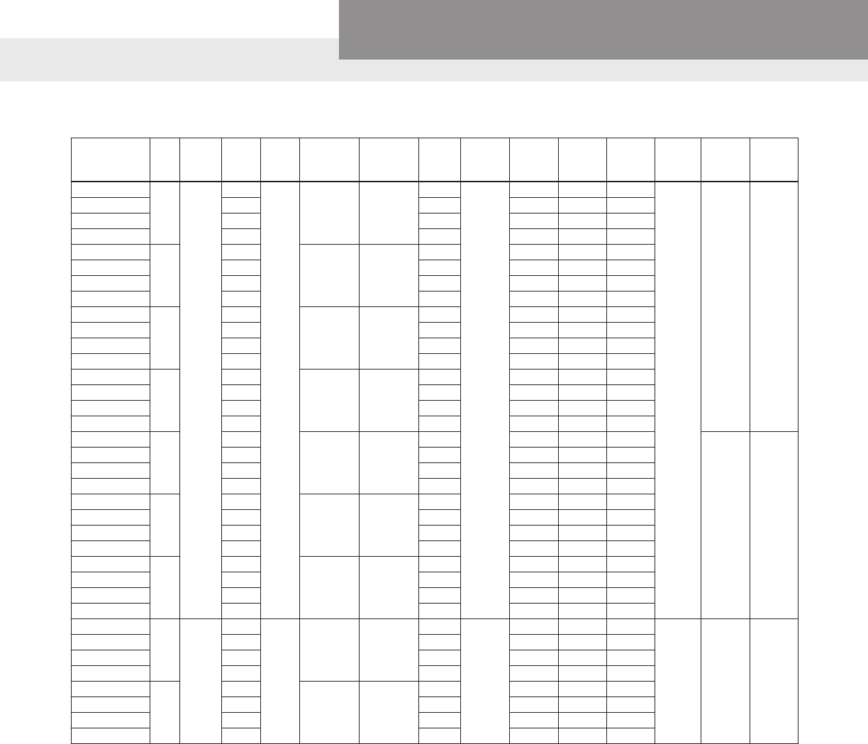
MODEL AND MOTOR INFORMATION (All ratings at 3 phase, 60 Hz. Consult factory for 3 phase, 50 Hz applications.)
1
st
Character – Discharge Size
4 = 4” 125 # ANSI Discharge Flange
2
nd
and 3
rd
Character – Pump Type / Design
NS = Dual Seal Non-Clog Pump with On-Winding Thermal Sensors
and Moisture Detection Sensors
4
th
Character – Mechanical Seals
1 = Standard Seal – the upper seal is carbon/rotary and ceramic/
stationary, the lower seal is carbon/rotary with ceramic/stationary
with BUNA elastomers and 304 stainless steel metal parts.
3 = Optional Lower Seal – silicon carbide/rotary and silicon carbide/
stationary with Viton elastomers and 304 SS metal parts is
recommended for applications with ne solids or abrasives.
5 = Optional Lower Seal – silicon carbide/rotary and tungsten
carbide/stationary with Viton elastomers and 304 SS metal parts
is recommended for applications with ne solids or abrasives.
5
th
Character – Motor RPM / Hertz
2 = 1750 RPM / 60 Hz 6 = 1450 RPM / 50 Hz
3 = 1150 RPM / 60 Hz
6
th
Character – Horsepower
K = 7.5 M= 15 P = 25 R = 40
L = 10 N = 20 Q = 30
NOMENCLATURE DESCRIPTION
7
th
Character – Voltage / Phase
2 = 200 / 3 4 = 460 / 3 6 = 380/400 / 3
3 = 230 / 3 5 = 575 / 3
8
th
Character – Impeller Code
A = 11.0” 10 HP 1150 RPM 40 HP 1750 RPM
20 HP 1450 RPM
B = 10.75” 30 HP 1750 RPM
C = 10.38” 25 HP 1750 RPM
D = 10.12” 7.5 HP 1150 RPM 15 HP 1450 RPM
E = 9.75” 20 HP 1750 RPM
G = 9.00” 15 HP 1750 RPM 10 HP 1450 RPM
K = 8.00” 10 HP 1750 RPM 7.5 HP 1450 RPM
M = 7.50” 7.5 HP 1750 RPM
T = SPECIAL TRIM
9
th
Character – Cord Length - Power and Sensor Cords
C = 25’ standard F = 50’ Optional
10
th
Character – Options
B = Silicon Bronze Impeller E = Epoxy Paint
F = Both Bronze Impeller and Epoxy Paint
Order
Number HP Phase Volts RPM Impeller
Dia. (In.)
Impeller
Code
S.F.
Amps
Service
Factor
Full
Load
Amps
Locked
Rotor
Amps
Power
Cable
Size
Sensor
Cable
Size
Frame
Size
Weight
(lbs.)
4NS12K2MC
7.5
3
200
1750
7.50 M
27.0
1.15
24.2 183.8 8/4
18/5
210TY 455
4NS12K3MC 230 23.4 21.0 160.0 8/4
4NS12K4MC 460 11.7 10.5 80.0 8/4
4NS12K5MC 575 9.4 8.4 64.0 14/4
4NS12L2KC
10
200
8.00 K
35.6 31.1 186.2 8/4
4NS12L3KC 230 31.0 27.0 162.0 8/4
4NS12L4KC 460 15.5 13.5 81.0 8/4
4NS12L5KC 575 12.3 10.8 64.0 14/4
4NS12M2GC
15
200
9.00 G
54.8 48.2 256.0 6/4
4NS12M3GC 230 47.8 42.0 222.0 8/4
4NS12M4GC 460 23.9 21.0 111.0 8/4
4NS12M5GC 575 19.1 16.8 88.7 10/4
4NS12N2EC
20
200
9.75 E
74.8 64.4 342.0 4/4
4NS12N3EC 230 65.0 56.0 298.0 6/4
4NS12N4EC 460 32.5 28.0 149.0 6/4
4NS12N5EC 575 26.0 22.4 119.0 10/4
4NS12P2CC
25
200
10.38 C
83.6 72.5 394.0 2/4
250TYS 890
4NS12P3CC 230 72.8 63.0 342.0 4/4
4NS12P4CC 460 36.4 31.5 171.0 4/4
4NS12P5CC 575 29.1 25.2 137.0 8/4
4NS12Q2BC
30
200
10.75 B
103.2 89.7 472.0 2/4
4NS12Q3BC 230 89.6 78.0 410.0 2/4
4NS12Q4BC 460 44.8 39.0 205.0 2/4
4NS12Q5BC 575 35.8 31.2 164.0 8/4
4NS12R2AC
40
200
11.00 A
132.8 114.4 600.0 1/0/4
4NS12R3AC 230 115.4 99.4 522.0 1/4
4NS12R4AC 460 57.7 49.7 261.0 6/4
4NS12R5AC 575 46.2 39.8 209.0 8/4
4NS13K2DC
7.5
3
200
1150
10.12 D
30.4
1.15
26.5 131.6 8/4
18/5 210TY 455
4NS13K3DC 230 26.4 23.0 114.4 10/4
4NS13K4DC 460 13.2 11.5 57.2 10/4
4NS13K5DC 575 10.6 9.2 45.8 14/4
4NS13L2AC
10
200
11.00 A
40.0 35.0 186.0 8/4
4NS13L3AC 230 34.8 30.4 161.0 8/4
4NS13L4AC 460 17.4 15.2 80.7 8/4
4NS13L5AC 575 13.9 12.2 64.5 12/4
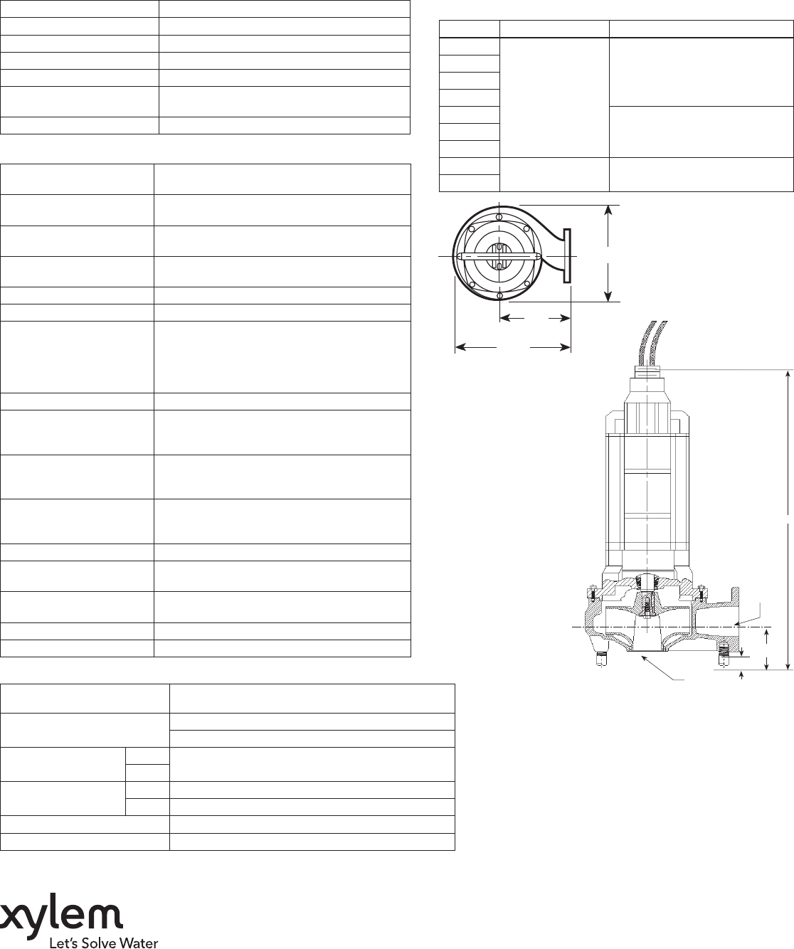
DIMENSIONS
(All dimensions are in inches. Do not use for construction purposes.)
19.75
12
15.5
DISCHARGE-
4" ANSI
125 # FLANGE
SUCTION
3.5
7.5
A
APPLICATION DATA
CONSTRUCTION DETAILS
STANDARD PARTS
Goulds is a registered trademark of Goulds Pumps, Inc. and is used under license.
© 2015 Xylem Inc. B4NS R1 March 2015
Xylem Inc.
2881 East Bayard Street Ext., Suite A
Seneca Falls, NY 13148
Phone: (866) 325-4210
Fax: (888) 322-5877
www.gouldswatertechnology.com
Maximum Solid Size 3"
Minimum Casing Thickness 5⁄16"
Casing Corrosion Allowance 1⁄8"
Maximum Working Pressure 100 PSI
Maximum Submergence 200 feet
Maximum Environmental
Temperature 40ºC (104ºF) ambient conditions
Maximum Starts Per Hour Maximum of 10 evenly spaced starts per hour
HP RPM "A" Dimensions (in.)
7½
1750
41.3
10
15
20
25
46.630
40
7½ 1150 41.3
10
Ball Bearing Lubricated for life bearings are designed for a
minimum L10 life of 30,000 hours.
210 and 250 Frame Single row Radial (upper)
Single row Thrust (lower)
Mechanical Seals –
Standard
Upper
Carbon/rotary and ceramic/stationary
Lower
Mechanical Seals –
Optional
Lower
Silicon carbide/rotary and tungsten carbide/stationary
Lower
Silicon carbide/rotary and silicon carbide/stationary
Standard Motor O-rings BUNA-N (nitrile)
Seal Chamber Oil SAE IOW
Power Cable – Type 1/0 / 4, 2/4, 4/4, 6/4, 8/4, 10/4, 12/4 SOW or
SOOW (see Model Info)
Control / Sensor Cable /
Type Type 18/5 SOW
Power Cable and
Cap Assembly
Leads have a BUNA-N grommet in addition to
being epoxy encapsulated
Power and Control Cable
Lengths
25’ standard, 50’ optional
Motor Enclosure Cast iron ASTM A-48 Class 30
Motor Shaft Series 416 Stainless steel
Motor Design
NEMA design “B” with copper windings and
designed to withstand 200 psi water pressure at
all seal locations. Air-lled NEMA 210TY frame
on 7.5, 10, 15 and 20 HP models. Air-lled NEMA
250TYS frame on 25 - 40 HP models.
Motor Insulation Rating Class "F" insulation
Motor Thermal Protection
Two (2) normally closed on-winding thermostats
open at 320º F (160º C), automatic reset closes at
221º F (105º C).
Motor Overload Protection
Class 10, ambient compensated, quick-trip
overload protection must be provided in control
panel.
Motor Moisture Protection
Two (2) moisture sensing probes in the oil-lled
seal chamber must be connected to a relay in
control panel.
Casing Cast iron ASTM A-48 Class 30
Impeller Cast iron ASTM A-48 Class 30 or optional cast
bronze ASTM B584 UNS C87600.
Impeller Type Two vane enclosed design for maximum ef-
ciency.
Casing/Impeller/Wear Ring Replaceable bronze wear ring
External Hardware Stainless steel
