538615 1 Goulds 1GD Submersible Grinder Pump Brochure
538615 1 Goulds 1Gd Sewage Grinder Pump Technical Brochure 538615_1_Goulds 1GD Sewage Grinder Pump Technical Brochure 538615_1_Goulds 1GD Sewage Grinder Pump Technical Brochure pdf pumpproducts
: Pump 538615 1 Goulds 1Gd Submersible Grinder Pump Brochure 538615_1_Goulds 1GD Submersible Grinder Pump Brochure pdf
Open the PDF directly: View PDF ![]() .
.
Page Count: 4
CU
S
®Tested to UL 778 and CSA 22.2 108 Standards
By Canadian Standards Association
File #LR38549
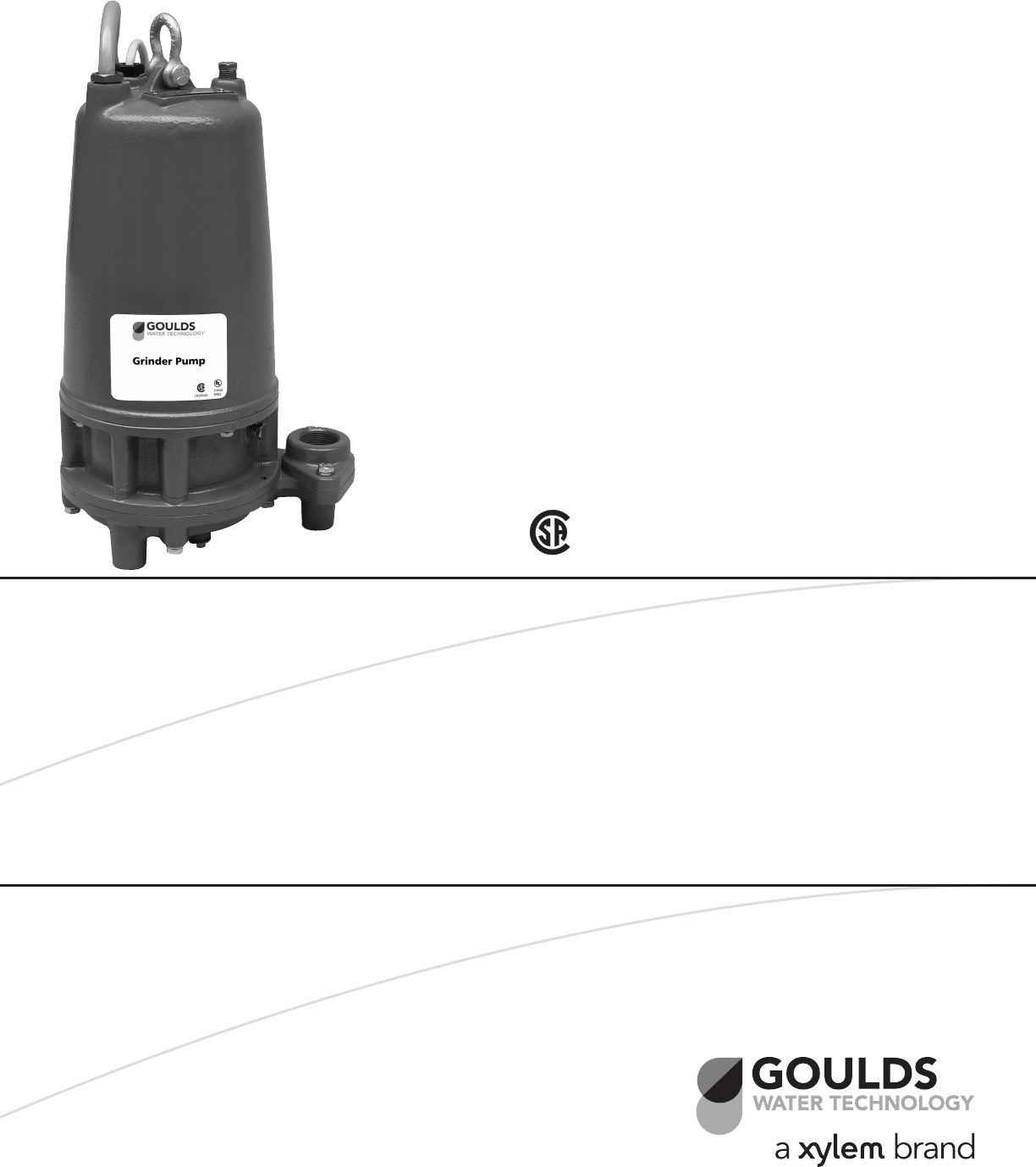
FEATURES
Single phase pumps now have built-in overload protection. See control panel
note on page 3.
Impeller: Silicon bronze, multi-vane semi-open, with pump-out vanes for
mechanical seal protection. Balanced for smooth operation.
Grinder Cutter System: The anti-roping design, hardened cutter is keyed to the
motor shaft for positive drive. The cutter ring is specially designed to be reversed
when the rst side wears out thus doubling its life and reducing maintenance
costs. The cutter system is designed and tested to pass items found in normal
wastewater.
Casing: Heavy duty cast iron, volute type for maximum efciency. Use with
A10-12 guide rail system for ease of installation and maintenance.
Dual Mechanical Seals: Silicon carbide vs. silicon carbide outer seal and ceramic
vs. carbon inner seal, stainless steel metal parts, BUNA-N elastomers. Upper and
lower shaft seals are positioned independently and are separated by an oil-lled
chamber. Optional Silicon/Tungsten Carbide outer seal available.
Optional Seal Sensor Probe: Located in oil-lled chamber. If pumpage should
begin to leak past lower seal it indicates to pump control panel a fault has
occurred. Requires optional Seal Fail Circuit in the control panel.
Fasteners and Pipe Plugs: 300 series stainless steel.
AGENCY LISTINGS
1GD
SUBMERSIBLE GRINDER PUMP
DUAL SEAL WITH OPTIONAL SEAL SENSOR PROBE
TECHNICAL BROCHURE
B1GD R2

PAGE 2
Wastewater
Goulds Water Technology
1st, 2nd and 3rd Characters – Discharge Size and Type
1GD = 1¼" discharge, grinder, dual seal
4th Character – Mechanical Seals
5 = silicon carbide/silicon carbide/BUNA – lower seal
and carbon/ceramic/BUNA – upper seal (standard)
3 = silicon carbide/tungsten carbide/BUNA – lower
seal and carbon/ceramic/BUNA – upper seal (op-
tional)
5th Character – Cycle/RPM
1 = 60 Hz/3500 RPM 5 = 50 Hz/2900 RPM
6th Character – Horsepower
G = 2 HP
7th Character – Phase/Voltage
1 = single phase, 230 V 5 = three phase, 575 V
2 = three phase, 200 V 6 = three phase, 380 V
3 = three phase, 230 V 8 = single phase, 208 V
4 = three phase, 460 V
NOMENCLATURE DESCRIPTION
8th Character – Impeller Diameter
A = 55⁄8", Standard C = 4¾"
B = 5¼" D = 4¼"
9th Character – Cord Length (Power and Sensor)
A = 20' (standard) F = 50'
D = 30' J = 100'
10th Character – Options
S = Seal fail, moisture sensing circuit1
E = Epoxy paint
Last Character – Option
H = Pilot duty thermal sensors1 (3 phase only!!)
1These options add a 2-wire or 4-wire sensor cord to the
pump and require optional control panel circuits to oper-
ate. See panel options on control panel bulletin BCP5.
APPLICATIONS
Designed for high head sewage applications where a
gravity system is not practical. Ideal for pressure sew-
age systems.
SPECIFICATIONS
Pump:
• Solids handling capabilities: 3" maximum
• Discharge: 11⁄4" NPT removable ange
• Capacities: up to 46 GPM
• Total heads: up to 106 feet TDH
Motor:
• 2 HP, 3450 RPM, 60 Hz
• Class "F" insulation
• Rated for continuous duty fully submerged
• Maximum Fluid Temperature:
104º F continuous duty, 140° F intermittent duty
Single Phase:
• 208 or 230 volt
• Built-in, auto reset, on-winding motor overload
Three Phase:
• 200, 230, 460 or 575 volt
• Class 10 ambient compensated, overload protection
required in control panel.
MOTORS
• Fully submerged in oil-lled chamber. High grade
turbine oil surrounds motor for more efcient heat
dissipation, permanent lubrication of bearings and
mechanical seal for complete protection against
outside environment.
• Class F insulation
• Single Phase: 2 HP, 208 or 230 volt, 60 Hertz,
3450 RPM, 14/4 power cord. Motor has built-in
overload with automatic reset. Start capacitor,
run capacitor and starting relay are required and
will be located in the control panel. See “Recom-
mended Control Panels” in chart on this bulletin.
• Three Phase: 2 HP, 200, 230, 460 or 575 V, 60 Hz,
3450 RPM. 14/4 STOW. Overload protection must
be provided in starter unit.
• Designed for Continuous Operation: Pump ratings
are within the motor manu facturer’s recommended
working limits and can be operated continuously
without damage when fully submerged.
• Bearings: Upper and lower heavy duty ball bearing
construction for precision positioning of parts and
to carry thrust loads.
• Power (Sensor) Cables: Severe duty rated, oil and
water resistant. Epoxy seal on motor end provides
secondary moisture barrier in case of outer jacket
damage and to prevent oil wicking. 20 foot standard
with optional lengths available.
• O-ring: Assures positive sealing against contami-
nants and oil leakage.
• Shaft: 300 series stainless steel, keyed design, short
overhang for minimum shaft deection.
• Pump is capable of running dry with out damage to
mechanical components.
PAGE 3
Wastewater
Goulds Water Technology
MODEL AND MOTOR INFORMATION
FEATURES (continued)
Effective with December 2005 (M05) Date Codes -
Single-Phase 1GD Pumps Contain a
Built-in, Auto Reset Overload.
Important Control Panel Requirements and Notes:
1) See panel bulletin BCP5 for other available options.
2) These pumps require a magnetic contactor, start and run
capacitors and a starting relay in the control panel.
3) CP-1GDB Capacitor packs with starting relays are avail-
able on product bulletin BCPCAP. They are for certied
panel shops to “build” into a custom panel. Field installing
capacitor packs into a S10020 or D10020 will negate the
UL listing on that panel and is therefore not permissible.
6
3
2
4
5
8
7
1
MATERIALS OF CONSTRUCTION
Order No. HP Phase Volts RPM Maximum
Amps
Locked
Rotor
Amps
KVA
Code
Full Load
Efciency Resistance Power
Cord
Weight
lbs.
% Start Line-Line
1GD51G1AA
2
1230
3450
15.5 96.0 P 79.0 1.37 0.62
14/4
STOW
20'
LONG
110
1GD51G8AA 208 17.5
1GD51G2AA
3
200 14.0 44.8 J 81.0
NA
1.8
105
1GD51G3AA 230 12.0 37.4 D 81.4 2.8
1GD51G4AA 460 6.0 18.7 11.1
1GD51G5AA 575 4.8 14.0 J 83.2 18.0
Pump
Order No.
Pump
Seal Fail
Circuit
Voltage /
Phase
Recommended
Control Panel
Simplex Duplex
1GD51G1A_
No 230 / 1 S1GD2 D1GD2
1GD51G8A_208 / 1 S1GD2 D1GD2
1GD51G1A_SYes 230 / 1 S1GD2H D1GD2J
1GD51G8A_S 208 / 1 S1GD2H D1GD2J
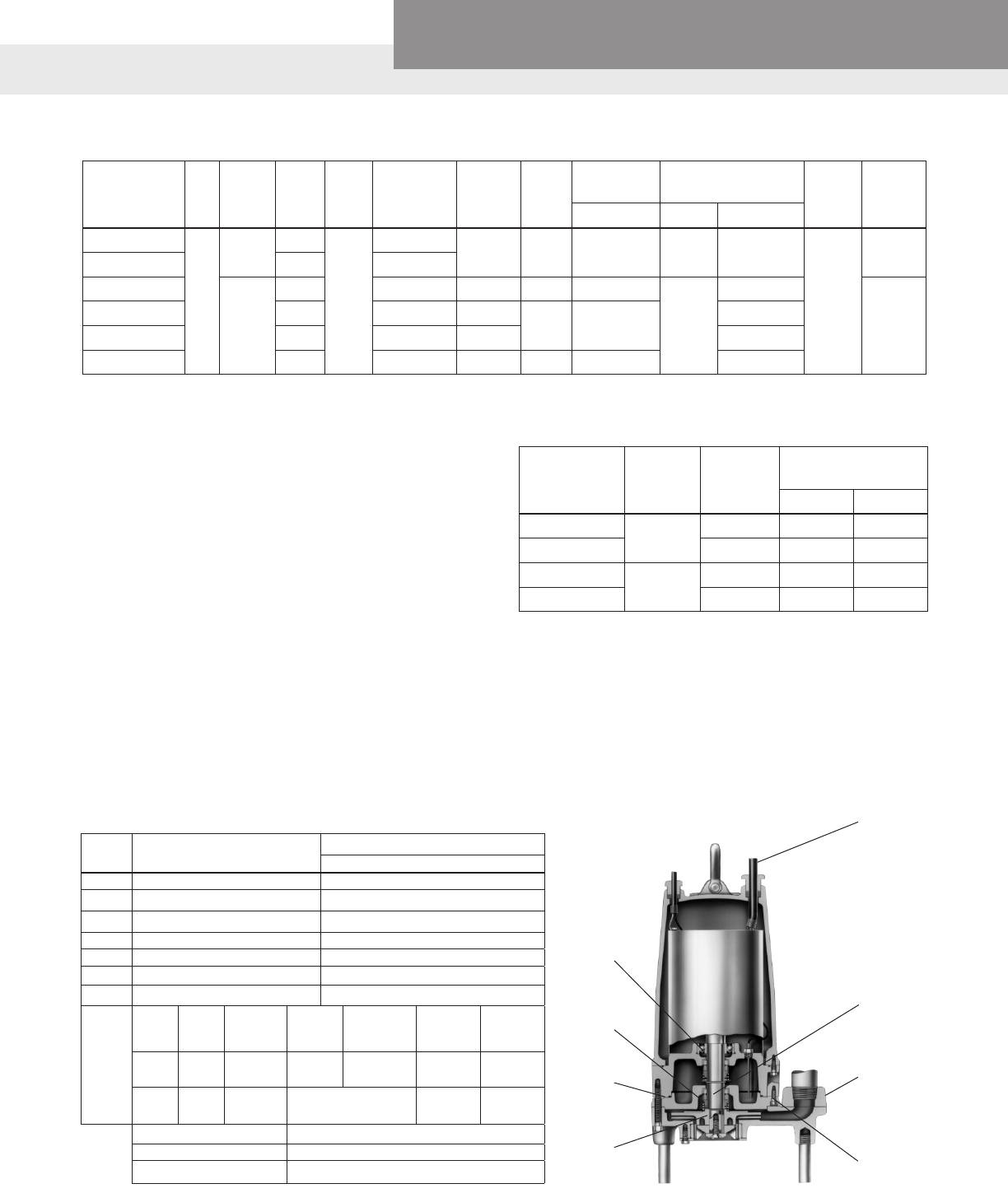
Item
No. Part Name Material
Standard
1Impeller, multi-vane 1179
2 Castings 1003
3 Shaft-Keyed 300 Series SS
4Fasteners 300 Series SS
5 Ball bearings Steel
6 Power cable STOW, 20 feet
7 O-ring BUNA-N
8
Outer
Mech.
Seal
No. Service Rotary Stationary Elas-
tomers
Metal
Parts
OPT 10K22 Heavy
duty
Silicon
Carbide
Tungsten
Carbide BUNA-N 300
Series SS
STD 10K28 Mild
abrasives Silicon Carbide BUNA-N 300
Series SS
Material Code Engineering Standard
1003 Cast iron — ASTM A48 Class 30
1179 Silicon bronze — ASTM C87600
ROTATION
KICKBACK
11
1
⁄
2
5
3
⁄
4
8
1
⁄
2
1
1
⁄
4
NPT
DISCHARGE
6
1
⁄
2
3
22
APPLICATION DATA
CONSTRUCTION DETAILS
STANDARD PARTS
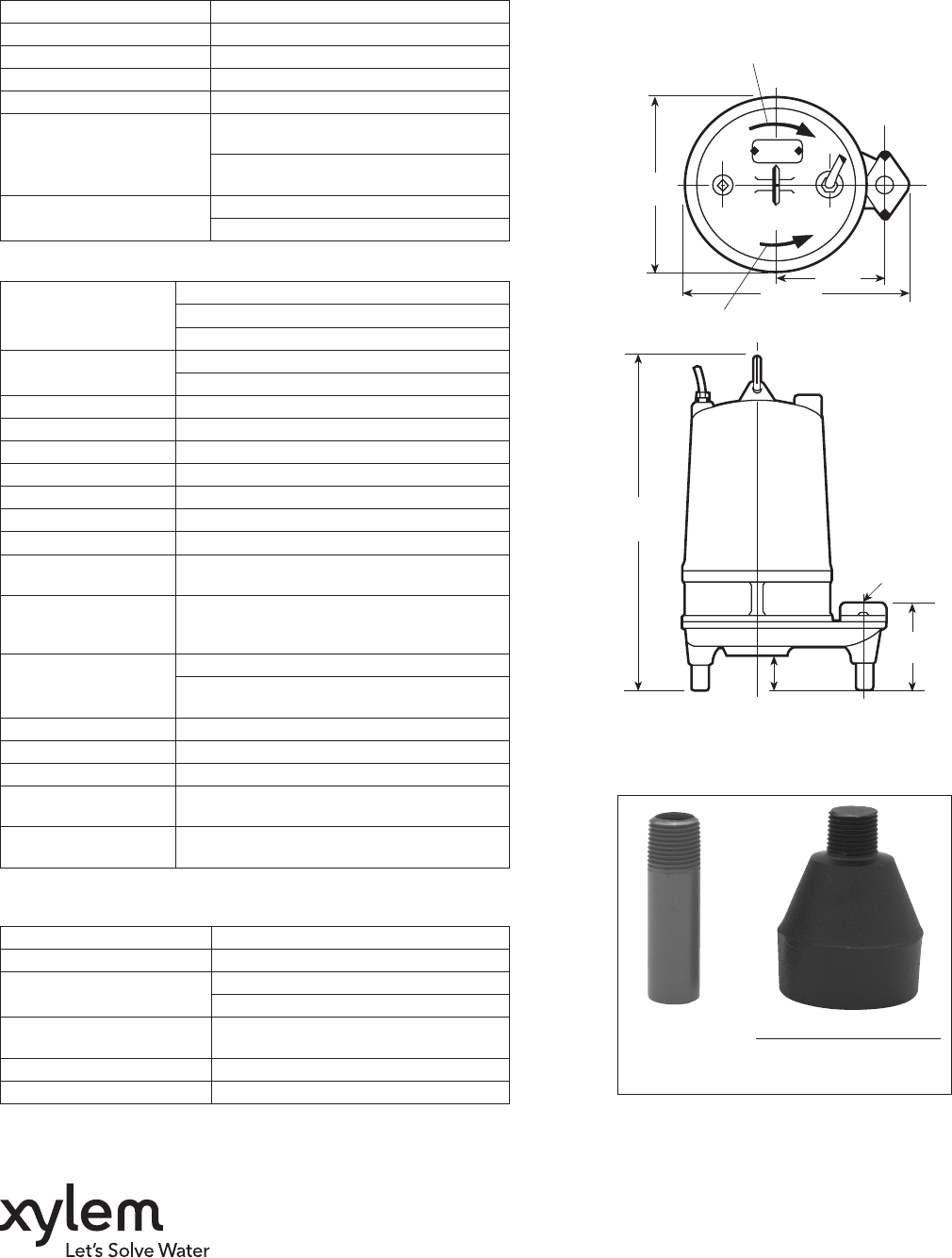
DIMENSIONS
(All dimensions are in inches. Do not use for construction purposes.)
Standard Optional Pump Legs
Foot Order No. 4K639
(Set of 3)
ROTATION
KICKBACK
111⁄2
53⁄4
81⁄2
11⁄4 NPT
DISCHARGE
61⁄2
3
22
Goulds is a registered trademark of Goulds Pumps, Inc. and is used under license.
© 2014 Xylem Inc. B1GD R2 November 2014
Xylem Inc.
2881 East Bayard Street Ext., Suite A
Seneca Falls, NY 13148
Phone: (866) 325-4210
Fax: (888) 322-5877
www.gouldswatertechnology.com
Maximum Solid Size N/A
Minimum Casing Thickness 5⁄16"
Casing Corrosion Allowance 1⁄8"
Maximum Working Pressure 50 PSI
Maximum Submergence 50 feet
Minimum Submergence
Fully submerged for continuous
operation
6" below top of motor for intermittent
operation
Maximum Environmental
Temperature
40ºC (104ºF) continuous operation
60ºC (140ºF) intermittent operation
Power Cable – Type
14/3, type SJTOW: single phase
14/4, type STOW: single phase
14/4, type STOW: all three phase
Sensor Cable – Type 16/2, type SJTOW: heat sensor or seal fail only
18/4, type SJTOW: seal/heat sensor
Motor Cover Gray Cast Iron – ASTM A48 Class 30
Bearing Housing Gray Cast Iron – ASTM A48 Class 30
Seal Housing Gray Cast Iron – ASTM A48 Class 30
Casing Gray Cast Iron – ASTM A48 Class 30
Impeller Cast Bronze – ASTM B584 C87600
Motor Shaft AISI 300 Series Stainless Steel
Motor Design NEMA 56 Frame, oil lled with Class F Insulation
Optional: Motor Seal
Fail (Moisture) Detection
Seal fail sensor in an oil-lled seal chamber.
Connect to an optional relay in control panel.
Optional: Motor
Thermal Protection
1Ø and 3Ø
Normally closed on-winding thermostats open
at 275º F (135 ºC) and close at 112º F (78º C).
Require terminal connection in the control panel.
Motor Overload
Protection
Single Phase:
Built-in, auto reset overload
Three Phase: require ambient compensated
Class 10 protection in the control panel.
External Hardware 300 Series Stainless Steel
Impeller Type Semi-open with pump out vanes on back shroud
Cutter
Two blades; type 440C stainless steel
Oil Capacity –
Seal Chamber
1.5 quarts
Oil Capacity –
Motor Chamber 4.5 quarts
Ball Bearing – Upper
Single row ball– SKF™ 6203-2Z
Ball Bearing – Lower
Single row ball – SKF™ 6206-2Z
Mechanical Seals – Standard Carbon/Ceramic; Upper
Silicon Carbide/Silicon Carbide - Lower
Mechanical Seals – Optional Silicon Carbide/Tungsten Carbide -
Lower
O-Ring – Stufng Box BUNA-N, AS 568A-256
O-Ring – Motor Cover BUNA-N, AS 568A-166
