Sec 3e REV 1 542525 Barnes Fiberglass Hard Piped Simplex Lift Station Specifications
542517 1 Barnes Fiberglass Hard Piped Simplex Lift Station Specifications 542517_1_Barnes Fiberglass Hard Piped Simplex Lift Station Specifications 542517_1_Barnes Fiberglass Hard Piped Simplex Lift Station Specifications pdf pumpproducts
: Pump 542525 1 Barnes Fiberglass Hard Piped Simplex Lift Station Specifications 542525_1_Barnes Fiberglass Hard Piped Simplex Lift Station Specifications pdf
Open the PDF directly: View PDF ![]() .
.
Page Count: 6
SECTION
PAGE
DATE
USA: (937) 778-8947 • Canada: (905) 457-6223 • International: (937) 615-3598
A Crane Co. Company
15
3E
www.cranepumps.com
Pre-Packaged Fiberglass Systems
6/15
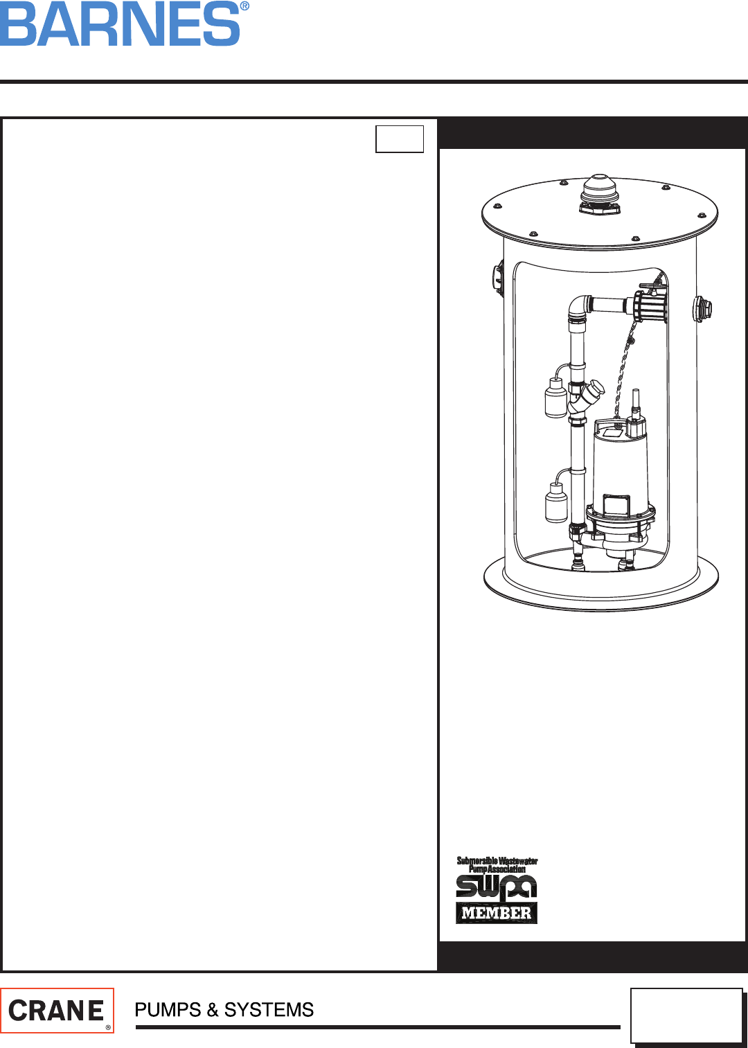
Simplex
Fiberglass Lift Station: Hard Piped
Specifi cations:
BASIN .................................. Fiberglass w/ 3” (76) Ballast Support Flange
DISCHARGE CONNECTION:
.............................................. SCH80 PVC/PP
Size ................ 1¼", 2", or 3" NPT, Female
INLET ................................... 4” (102) (For Field Installation)
COVER: Fiberglass ....... 24" (609) thru 30" (762)
One piece, Grass Green with 2" (51)
Bug-Free Vent.
Aluminum ........ ¾ Hatch, w/2" (51) Bug-Free Vent (Frogmouth)
ELECTRICAL COUPLING ... Qty. of 1, 2" NPT, PVC
ISOLATION VALVE:
Design ............. Full Port True Union
Material .......... PVC
Size ................. 1¼” NPT, 2" NPT, or 3" NPT
LIFTING DEVICE ................. 1/2” Dia. (13) Polypropylene Rope with
Knots in 12” (305) increments. Breaking
Strength of 3750 lbs. (1701kg)
HARDWARE ....................... 300 Series Stainless Steel
DISCHARGE PIPING ........... SCH80 PVC/PP
LEVEL CONTROLS:
Floats .............. Two fi eld installed fl oats provided, one wide
angle piggy back for on/off operation and one
alarm fl oat
Cord ............... 15' SJOW
Float Material .. Polypropylene
3" BALL CHECK VALVE:
Housing ........... Cast Iron, with PVC cleanout
Ball ................. Buna-N
1¼" AND 2" BALL CHECK VALVE:
Housing ........... PVC
Ball ................. Buna-N
REMOTE ALARM ................ NEMA 3R Enclosure, 120V, 50/60Hz,
Alarm Light, 85 db Audible Horn,
Barnes P/N 126307
NOTE: Pump NOT included with part numbers shown in catalog.
See online ePump confi gurator to build a station with a pump.
NOTE: Designed for use with single phase pumps having a power
cord with attachment plug end for use with piggyback fl oats.
inches
(mm)
Simplex Fiberglass Lift Station:
Hard Piped
1¼" NPT Discharge, or
2" NPT Discharge, or
3" NPT Discharge
SECTION
PAGE
DATE
Pre-Packaged Fiberglass Systems
USA: (937) 778-8947 • Canada: (905) 457-6223 • International: (937) 615-3598
A Crane Co. Company
16
3E
www.cranepumps.com
Simplex
Fiberglass Lift Station: Hard Piped
6/15
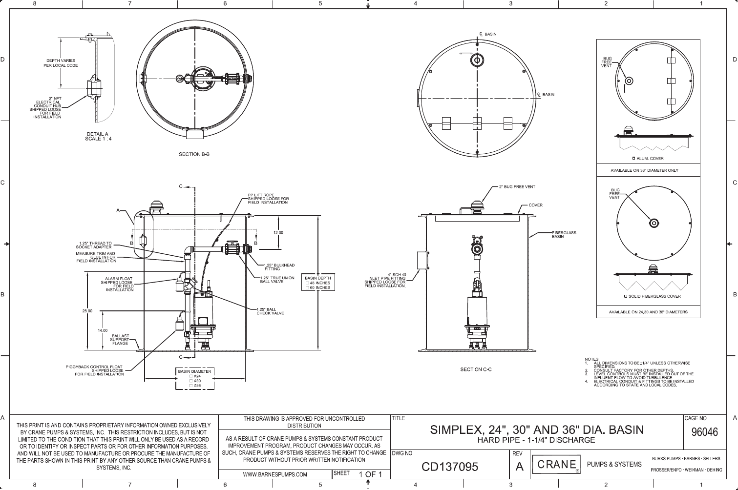
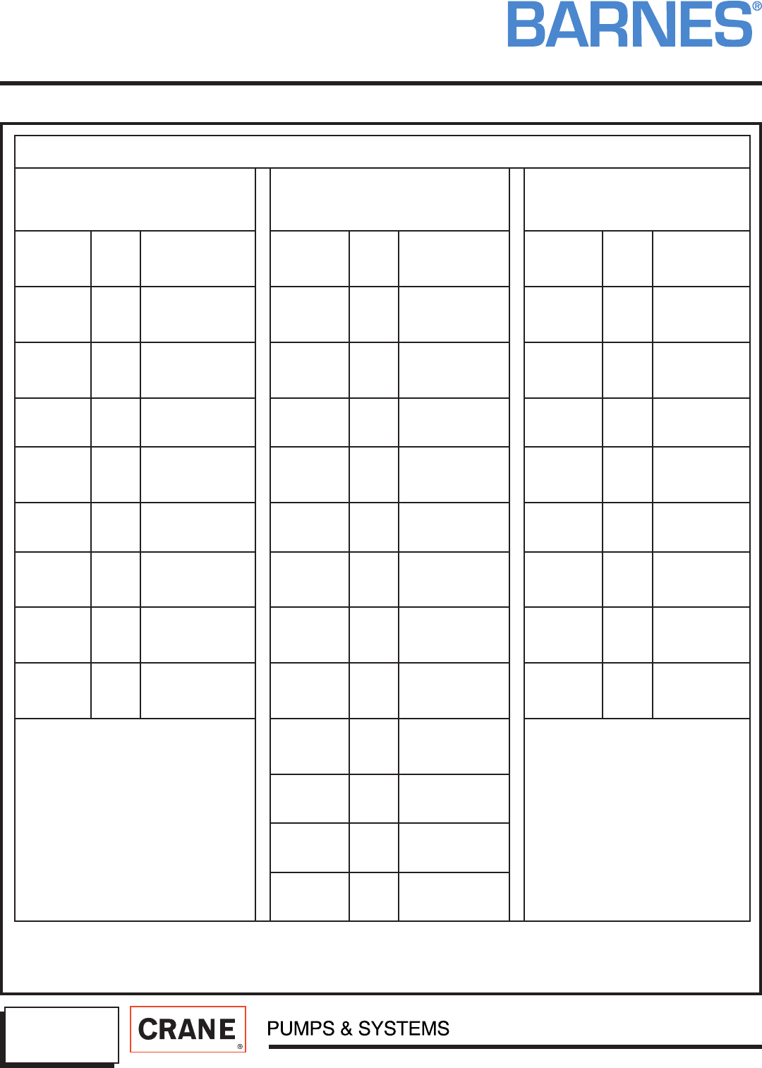
SIMPLEX HARD PIPED PART NUMBERS
PGP SERIES GRINDER PUMPS
1.25" X 1.25"
REF: DRAWING CD137095
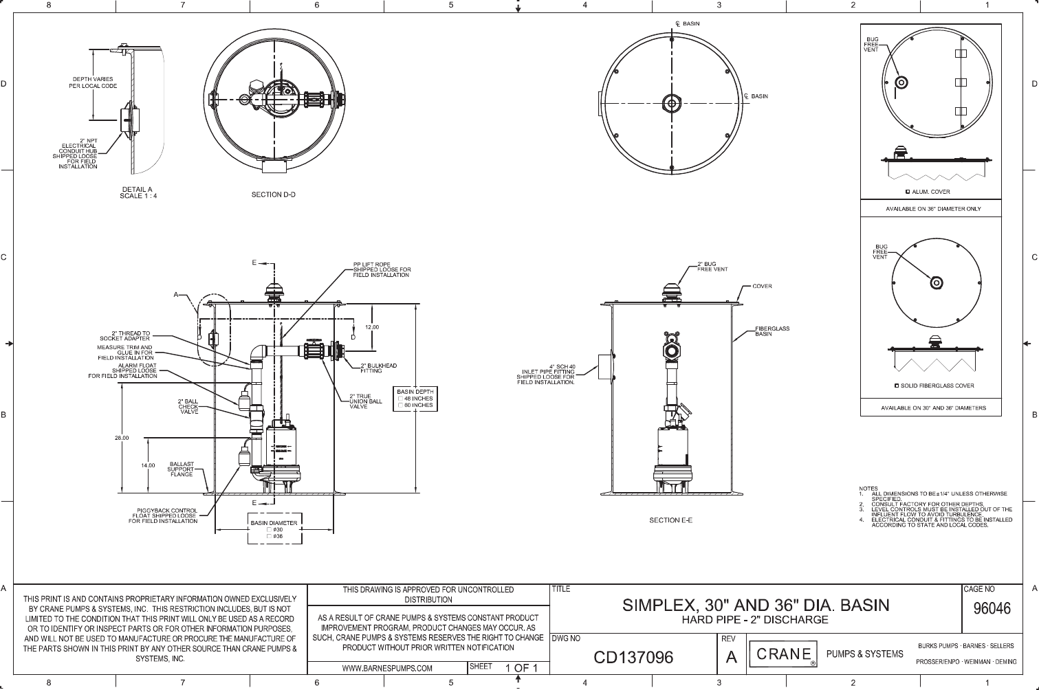
2" SEWAGE EJECTORS & EFFLUENT
PUMPS
2" X 2"
REF: DRAWING CD137096
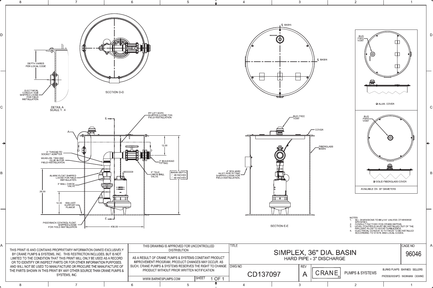
3" DEWAGE EJECTOR PUMPS
3" X 3"
REF: DRAWING CD137097
ASSEMBLY
PART
NUMBER
PUMP
VOLT DESCRIPTION
ASSEMBLY
PART
NUMBER
PUMP
VOLT DESCRIPTION
ASSEMBLY
PART
NUMBER
PUMP
VOLT DESCRIPTION
137572 240V
24 X 48 SOLID
FIBERGLASS
COVER
137580 120V
30 X 48 SOLID
FIBERGLASS
COVER
137592 120V
36 X 48 SOLID
FIBERGLASS
COVER
137573 240V
24 X 60 SOLID
FIBERGLASS
COVER
137581 120V
30 X 60 SOLID
FIBERGLASS
COVER
137593 120V
36 X 48
ALUMINUM
HATCH
137574 240V
30 X 48 SOLID
FIBERGLASS
COVER
137582 120V
36 X 48 SOLID
FIBERGLASS
COVER
137594 120V
36 X 60 SOLID
FIBERGLASS
COVER
137575 240V
30 X 60 SOLID
FIBERGLASS
COVER
137583 120V
36 X 48
ALUMINUM
HATCH
137595 120V
36 X 60
ALUMINUM
HATCH
137576 240V
36 X 48 SOLID
FIBERGLASS
COVER
137584 120V
36 X 60 SOLID
FIBERGLASS
COVER
137596 240V
36 X 48 SOLID
FIBERGLASS
COVER
137577 240V
36 X 48
ALUMINUM
HATCH
137585 120V
36 X 60
ALUMINUM
HATCH
137597 240V
36 X 48
ALUMINUM
HATCH
137578 240V
36 X 60 SOLID
FIBERGLASS
COVER
137586 240V
30 X 48 SOLID
FIBERGLASS
COVER
137598 240V
36 X 60 SOLID
FIBERGLASS
COVER
137579 240V
36 X 60
ALUMINUM
HATCH
137587 240V
30 X 60 SOLID
FIBERGLASS
COVER
137599 240V
36 X 60
ALUMINUM
HATCH
137588 240V
36 X 48 SOLID
FIBERGLASS
COVER
137589 240V
36 X 48
ALUMINUM
HATCH
137590 240V
36 X 60 SOLID
FIBERGLASS
COVER
137591 240V
36 X 60
ALUMINUM
HATCH
IMPORTANT!
- Pump NOT included with part numbers shown above. See online ePump confi gurator to build a station with a pump.
- Designed for use with single phase pumps having a power cord with attachment plug end for use with piggyback fl oats.
- Vertical PVC pipe to be fi eld cut on one end and glued at top to accomodate varying pump heights.
www.cranepumps.com
SECTION
PAGE
DATE
USA: (937) 778-8947 • Canada: (905) 457-6223 • International: (937) 615-3598
A Crane Co. Company
Pre-Packaged Fiberglass Systems
S
3E
6/15
Specifi cations
Simplex Fiberglass Lift Station: Hard Piped
DESCRIPTION: The manufacturer shall furnish a complete Pump
Station(s). The pump station shall consist of a basin package, high level
alarm and pump.
• The Basin Package shall include the following: fi berglass basin with
anti-fl otation collar, BAF lift out system with stainless steel guide rails,
isolation valve, mechanical fl oats, basin cover, check valve, stainless
lifting chain, fi eld locatable conduit fi tting, and bug free station vent. All
equipment in the wet well shall be capable of constant submerge in
sewage to a minimum depth of 30 feet without electrical power being
energized.
• The High Level Alarm Panel shall include a water-tight panel with a
top mounted Alarm light, a test/silence switch, a power on light and
an 85db (A) alarm horn with a mechanical fl oat. The liquid level alarm
system is designed specifi cally for lift pump chambers and sump pump
basins. The fl oat switch is lowered into the tank and secured at the
desired alarm level. When the liquid rises (high level alarm) or lowers
(low level alarm), the fl oat tips and activates the horn and light on the
alarm panel.
• The Pump (optional) shall include a Barnes Grinder, Effl uent, or
Sewage Ejector, and shall be selected based on the hydraulic
requirements of the system.
SHOP DRAWINGS AND MANUALS: After receipt of notice to proceed,
the manufacturer shall furnish the engineer a minimum of eight (8) sets
of shop drawings detailing the equipment to be furnished including
dimensional data and materials of construction. The engineer shall
promptly review this data, and return two (2) copies to the manufacturer
as approved, or approved as noted. Upon receipt of accepted shop
drawings, the manufacturer shall proceed with order entry and fabrication
of the equipment. Prior to completion of equipment delivery, the
manufacturer shall supply four (4) copies of Operation and Maintenance
Manuals to the owner, and one (1) copy of the same to the engineer.
PRE-APPROVAL OF MANUFACTURER: The system design is detailed
in the drawings. Any pump manufacturer not specifi ed, but wishing to
be pre-approved as an acceptable supplier shall submit a complete
hydraulic analysis based on the design detailed in the drawings at least
fi fteen days prior to bid date. All manufacturers must have been in the
business of manufacturing complete pump stations for a minimum of ten
years. Manufacturer Representatives, Distributors, or Packagers will not
be considered to be manufacturers. Manufacturer must demonstrate to
the satisfaction of engineer that the proposed pump equipment will meet
system fl ows and heads required. In addition, pre-submittal must also
demonstrate to the satisfaction of the engineer that the equipment being
proposed meets or exceeds all performance and safety requirements,
materials of construction, and user benefi ts of the specifi ed equipment.
Only pre-approved pump station manufacturers will be considered. All
bids utilizing manufacturers not pre-approved will be considered non-
responsive.
ACCEPTABLE MANUFACTURER(S): Acceptable pump station
manufacturer(s) are Barnes pumps as manufactured by Crane Pumps &
Systems., or pre-approved equal.
CORROSION PROTECTION: All materials exposed to wastewater shall
have inherent corrosion protection: i.e., painted cast iron, fi berglass,
stainless steel, PVC.
STATION CONFIGURATION: Basins shall be supplied in a wet well
confi guration.
LEVEL DETECTION: Level detection for controlling pump and alarm
operation shall be accomplished by use of a detection mechanism
specifi cally designed for use in a sewage using an all stainelss steel band
clamp. Switches utilized in the system shall be hermetically sealed in a
submersible, watertight protective casing. Level detection mechanism
shall be a wide angle, pipe mounted, piggy back mechanical fl oats.
Level detection mechanism shall not require any regular, preventive
maintenance. The level detection mechanism shall consist of one
piggyback on/off pump control fl oat and one high level mechanical fl oat.
The level controls shall be serviceable without the need for a confi ned
space entry as defi ned by OSHA. Use of mercury fl oats will not be
acceptable.
SHUT-OFF VALVE: The pump discharge shall be equipped with a factory
installed, manual gate valve with separate union. Gate valves shall be,
constructed of (PVC(1-1/4” and 2”) Brass (3”)) , with a minimum rated
pressure of 150 PSI (10.6 kgs/sq. meter). All valves shall be operable
from ground level. Shut off valve must be replaceable without excavating
basin exterior. Shut off valves shall be each equal to the size of the
station discharge.
BASIN CONSTRUCTION AND ASSEMBLY: The basin shall be
fi berglass reinforced polyester resin with a 3" (76.2 mm) ballast support
fl ange. The basin shall be furnished with one fl exible inlet fl ange (shipped
loose to facilitate fi eld location) to accept a 4.50" (114 mm) OD DWV
pipe. Inlet location can vary to accommodate ease of installation. (See
installation instructions or consult factory for details.) Basin capacities
and dimensions shall be as shown on the contract drawings or as
specifi ed herein. The basin FRP wall laminate thickness shall vary with
the wetwell depth to provide the aggregate strength to meet the tensile
and fl exural physical property requirements. The basin FRP wall laminate
must be designed to withstand wall collapse or buckling based on a
hydrostatic pressure of pounds per square foot, a saturated soil weight of
120 pounds per cubic foot, a soil modulus of 700 pounds per square foot.
Basin must comply with the pipe stiffness values as specifi ed in ASTM
D 3753. The basin laminate must be constructed to withstand or exceed
150% of the assumed loading on any depth. The fi nished FRP laminate
will have a Barcol hardness of at least 90% of the resin manufactures
specifi ed hardness for the fully cured resin. The Barcol Hardness shall be
the same for both interior and exterior surfaces. Manufacture must submit
documentation including calculation and production certifi cation that
basin (s) on the project are in compliance with the above requirements.
All piping inside the basin silhouette shall be at a level in the station
that is lower than the frost depth or depth of bury specifi ed for the low
pressure sewer piping, whichever is lowest.
Fiberglass cover shall be grass green color. Steel cover shall be black in
color. Aluminum cover shall be natural silver color.
All discharge piping shall be constructed of Schedule 80 PVC and
terminate outside the stations with a bulkhead female NPT fi tting. The
manufacturer shall guarantee all bulkhead penetrations watertight.
PUMP REMOVAL SYSTEM: Each basin shall be equipped with a 300
series stainless steel pipe guide rail assembly to facilitate removal of the
pump(s) from ground level. A stainless steel lifting chain with harness
shall be supplied for pump removal. Pump removal system must not
require the loosening of fasteners to facilitate pump removal, and shall
provide for automatic alignment and re-connection of discharge piping for
the replacement pump. Pump replacement shall be accomplished while
the basin is full of sewage without the need to dewater the basin.
WARRANTY: The manufacturer shall provide a warranty of twenty-
four (24) months after date of manufacture. The owner will return any
equipment found to be defective to the manufacturer for inspection and
validation of the defect. Defective equipment will be repaired or replaced
and shipped back to customer at no charge. Consult factory for extended
warranty information.
End
FILE: SPEC40A
Word File