DaytonPumpsManual 1XHV4 & V5 544733 2 PHCC Pro Series C8 Chemical Pump Instruction Manual
544734 2 Phcc Pro Series C8 Chemical Pump Instruction Manual 544734_2_PHCC Pro Series C8 Chemical Pump Instruction Manual 544734_2_PHCC Pro Series C8 Chemical Pump Instruction Manual pdf pumpproducts
: Pump 544733 2 Phcc Pro Series C8 Chemical Pump Instruction Manual 544733_2_PHCC Pro Series C8 Chemical Pump Instruction Manual pdf
Open the PDF directly: View PDF ![]() .
.
Page Count: 7

PHCC Pro Series Chemical
Resistant Pumps
Operating Instructions C8050 & C8100
Please read and save these instructions. Read carefully before attempting to assemble, install, operate or maintain the product described.
Protect yourself and others by observing all safety information. Failure to comply with instructions could result in personal injury and/or
property damage! Retain instructions for future reference.
Description
PHCC Pro Series submersible chemical resistant pumps are rated for continuous
duty. Pumps are strong and dependable, and when used intermittently in a sump
application, extends the life of the pump. PSC motor design saves energy, reduces
operation costs and provides better service. Intended for pumping non-flammable
fluids compatible with pump component materials.
General Safety Instructions
SAVE THESE INSTRUCTIONS.
This manual contains important
SAFETY WARNINGS and OPERATING
INSTRUCTIONS for the C8050 & C8100
pumps. You will need to refer to it
before attempting any installation or
maintenance.
ALWAYS keep these instructions with
the unit so that they will be easily
accessible.
Failure to read and follow these
warnings and instructions could result
in property damage, serious injury, or
death.
Risk of electric
shock. To reduce
this risk, observe the following
precautions.
•ALWAYS disconnect the pump from
the power source before servicing or
making adjustments.
•NEVER handle the pump or motor
with wet hands or when standing on
a wet or damp surface while the
pump is plugged into the power
source.
•MAKE SURE THERE IS A PROPERLY
GROUNDED RECEPTACLE
AVAILABLE. This pump is wired
with a 3-prong grounded plug. To
reduce the risk of electric shock, be
certain that it is only connected to a
properly grounded, 3-prong
receptacle (preferably with ground
fault circuit interrupt). If you have a
2-prong receptacle, have a licensed
electrician replace it with a 3-prong
receptacle according to local codes
and ordinances.
•NEVER bypass grounding wires or
remove the ground prong from the
plug.
•DO NOT use an extension cord. The
electrical outlet should be within the
length of the pump’s power cord,
and at least 4 feet above the floor
Specifications
C8050 C8100
HP 1/2 1
Motor Type PSC PSC
Voltage 60 Hz 115 VAC 115 VAC
Amps 4.7 11.3
Water Flow (GPM) at Total Feet of Head
5 Ft. 74 90
10 Ft. 64 82
15 Ft. 51 69
20 Ft. 40 61
25 Ft. 27 53
30 Ft. 13 45
35 Ft. -- 37
40 Ft. -- 24
Max Head 36 Ft. 49 Ft.
Max Dia Solids 1/4” 3/8”
Dimensions
C8050 C8100
HP 1/2 1
Pump Discharge 2” 2”
Materials of Construction
Pump Housing 304 SS 304 SS
Impeller 304 SS 304 SS
Motor Casing
304 SS 304 SS
Inlet Screen 304 SS 304 SS
Motor Shaft 304 SS 304 SS
Mech. Seals (2) Carbon/Ceramic/Viton
Fasteners 304 SS 304 SS
Overall Dimensions
Length 9.1” 10.4”
Width 6.3” 7.5”
Height 16.3” 18.1”
Weight (lbs.) 23.0 46.0
level to minimize potential hazards
from flood conditions.
•DO protect the electrical cord from
sharp objects, hot surfaces, oil, and
chemicals. Avoid kinking the cord.
•MAKE SURE the supply circuit has a
fuse or circuit breaker rated to handle
the power requirements noted on the
nameplate of the pump.
•NEVER install the pump in locations
classified as hazardous in accordance
with the National Electrical Code,
ANSI/NFPA 70.
•ALWAYS install the pump in
accordance with the National Electric
Code and all applicable local codes
and ordinances. All wiring should be
performed by a licensed electrician.
To reduce the risk
of hazards that can
cause injury or property damage,
observe the following precautions.
•DO NOT use the power cord or strain
relief to carry the pump. Use the
pump handle.
•DO NOT operate the pump if it has
been damaged in any way.
•ALWAYS use a float switch that is
compatible with the pumped fluid.
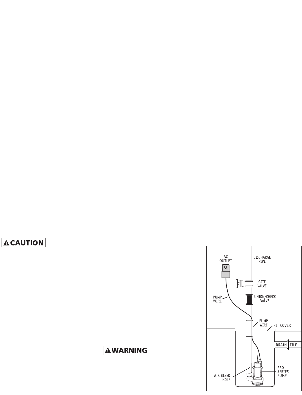
•DO drill an air bleed hole - 1/8”
(3.2mm) - in the discharge pipe when
a check valve is used. Drill the hole
angled toward the bottom of the
sump to avoid splashing fluid outside
the sump pit. If a hole is not drilled
above the pump, an air lock may
prevent the pump from operating.
The best location for the hole is above
the normal fluid level. The hole must
be drilled below the check valve.
•DO NOT use pump in pits handling
f
luids that are not compatible with the
pump component parts. Refer to the
chemical compatibility chart on page 4.
•DO NOT disassemble the pump.
When service is required, contact
your dealer for additional directions.
NOTE: After the initial installation, be
sure to check the operation by filling
the sump and observing the pump
operation through one full cycle. For
continuous duty operation, the pump
must be submerged at least 3/4 of the
depth of the pump at all times. In
instances where the discharge line is
exposed to freezing temperatures, the
pipe must be sloped downward so any
remaining water will drain out. Failure
to do so will prevent water from exiting
the sump and damage the pump if the
line freezes.
Installation
PRIOR TO INSTALLATION
1. Visually inspect your pump. Products
may be damaged during shipping. If
the product has been damaged,
contact your place of purchase.
2. Thoroughly read the instructions
provided to learn specific details
regarding installation and use. This
manual should be retained for future
reference.
INSTALLING THE PUMP
This installation
must be in
accordance with the National Electric
Code and all applicable local codes and
ordinances.
1. Use a pit that conforms to all local
codes and is large enough to
accommodate the pump and float
switch.
2. Clean the pit of all debris. The pump’s
intake screen must be kept clear.
3. The pump should not be set directly
onto a clay, earthen, or sand base.
You may install bricks or blocks under
the pump to provide a solid base.
4. The pump should be level.
5. Install discharge plumbing according
to local, regional and state codes.
Rigid PVC pipe is recommended.
6. The discharge outlets on
the pumps
are 2”. Try to match the size of the
discharge pipe to the size of the outlet
on the pump to maintain the
optimum pumping capacity.
7.
An in-line check valve is recommended
to prevent back-flow. This check valve
is mandatory when sharing a discharge
line with another pump (i.e. a back-up
pump or a second primary pump).
2
PHCC Pro Series Operating Instructions
PHCC Pro Series Chemical
Resistant Pumps
C8050 and C8100
General Safety Instructions
(Continued)

NOTE: When using a check valve, an air
bleed hole of 1⁄8” (3.2mm) needs to be
drilled in the discharge pipe. The hole
should be below the check valve, but
above the water line. A small stream of
water will escape through this air bleed
hole when the pump is running, so the
hole should be drilled at an angle
toward the bottom of the sump pit.
8. Install a gate valve or ball valve as
required by any codes.
9. Secure the power cord to the
discharge pipe with wire ties or
clamps to prevent interference with
the float assembly (if used).
10. A pit cover is recommended for all
installations as a safety measure,
and to prevent debris from falling
into the pit.
11. In instances where the discharge
line is exposed to freezing
temperatures, the pipe must be
positioned in a downward slope so
any remaining water will drain
away. Failure to do this will prevent
water from exiting the pit and
damage the pump if the line freezes.
COMPLETING THE INSTALLATION
1. After the initial installation, be sure
to check the pump operation by
filling the sump with water and
observing the pump through one full
cycle.
NOTE: When the pump activates, it
should have a “normal pumping”
sound. Any abnormal sound, vibration,
or lack of output is the signal of a
problem. Stop the pump and refer to
the troubleshooting guide.
2. Replace the pit cover making sure
not to pinch or crimp the pump wire
with the cover. The pit cover either
has a ‘hole punch’ that will allow the
cord to be passed through or one can
be drilled.
Operation
OPERATING THE PUMP IN A
CONTINUOUS DUTY APPLICATION
C8050 and C8100 pumps are rated for
continuous duty and may be used in
applications requiring continuous
pumping including fountains, ponds,
etc. For use in any continuous duty
application the pump should be
plugged directly into the wall outlet
without the use of a controller. The
outlet must be a single phase properly
grounded 3-prong receptacle, 115V,
60Hz (preferably with ground fault
circuit interrupt). For continuous duty
operation, the pump must be submerged
at least 3/4 of the depth of the pump at
all times.
Maintenance
Maintenance should be performed 1-2
times per year.
1. Remove all debris from the bottom
of the pit.
2. Remove all debris floating in the
water.
3. Remove all debris from the float
switch.
4. Fill the pit with water. Make sure
pump turns on at the intended level.
5. While the pump is running, make
sure pump is evacuating water at a
good pace.
6. While the pump is running, make
sure a stream of water is escaping
from the air bleed hole. If not, clear
the hole of any deposits or debris.
Models C8050 and C8100
3
PHCC Pro Series Operating Instructions
Installation (Continued)

4
PHCC Pro Series Operating Instructions
PHCC Pro Series Chemical
Resistant Pumps
C8050 and C8100
Chemical Compatibility Chart
Beer
Beet Sugar Liquids
Calgon
Carbonic Acid
Cider
Coffee
Cream
Detergents
Epsom Salts (Magesium Sulfate)
Ethylene Glycol (Antifreeze)
Formaldehyde
Fruit Juice
Glycerine
Grape Juice
Hydrogen Peroxide
Lubricants
Milk
Cotton Seed Oil
Linseed Oil
Soybean Oil
Potassium Bromide
Potassium Carbonate
Potassium Chloride
Sea Water
Sodium Bicarbonate
Sodium Bisulfate
Sodium Bisulfite
Sodium Carbonate
Sodium Chlorate
Sodium Chloride
Sodium Cyanide
Sodium Silicate
Sodium Sulfate
Sodium Sulfide
Sodium Thiosulphate ("Hypo")
Soy Sauce
Stearic Acid
Stoddard Solvent
Tanning Liquors
Tomato Juice
Vegetable Juice
Vinegar
Mine Acid Water
Fresh Water
Salt Water
Whiskey and Wines
White Liquor (Pulp Mill)
White Water (Paper Mill)
Notes:
1. The above list of chemicals is based on the chemical resistance of the pump component materials (304 Stainless Steel pump
housing, motor housing, impeller & hardware and with the carbon/ceramic/Viton mechanical shaft sealand PVC-jacketed line
cord). It is based upon information from material suppliers and careful examination of available published information.
2. Since the resistance of metals, plastics and elastomers can be affected by concentration, temperature, presence of other
chemicals and other factors, the above listing should only be considered as a general guide.
3. It is the responsibility of the user to determine the suitability of the pump with the pumped fluid.

The pump will not start or run
Thermal protector tripping or not
functioning
Pump starts and stops too frequently
Pump will not shut off
1.
Pump is not plugged in
2.
Water is not high enough to
activate the pump
3.
Open circuit
4.
Poor power source
5.
Low voltage
6.
Bad power cable
7.
Locked impeller
8.
Defective float switch (if used)
9.
Defective pump
1.
Locked impeller
2.
Incorrect power supply
3.
Overburdened due to heavy sand
content in the water
4.
Pump running continuously with no
water present
1.
Water flowing back from pipe
2.
Float switch mounted too low (if used)
3.
Malfunctioning float switch
(if used)
1.
Clogged or frozen discharge
2.
Blocked inlet strainer
3.
Defective float switch (if used)
4.
Check valve installed with no air
bleed hole in pipe or pump
5.
Check valve is stuck or installed
upside down
1. Plug pump in properly (see
instructions)
2. Make sure float switch is positioned
properly
3. Check circuit breaker or fuse, and GFI
reset button
4. Check circuit line wires and cable*
5. Check line wires and source voltage*
6. Replace with new cable*
7. Remove strainer and clear obstruction
8. Replace float switch with new float
switch
9. Replace pump with new pump
1. Remove strainer and clear obstruction
2. Check power supply source and voltage
3. Use water filter or replace with a
higher horsepower pump
4. Check float switch
1. Install or replace check valve
2. Raise float switch
3. Replace float switch with new float
switch
1. Clear blockage or thaw frozen line
2. Clear debris from inlet strainer
3. Replace float switch with new float
switch
4. Drill a bleed hole in the discharge pipe,
or clean debris from the existing hole
in the pipe or pump
5. Reverse or replace check valve. Make
sure the check valve is installed with
the flow arrow pointing up and out of
the pit.
5
PHCC Pro Series Operating Instructions
Models C8050 and C8100
Troubleshooting Chart
Symptom Possible Cause(s) Corrective Action
*Consult a licensed electrician

6
PHCC Pro Series Operating Instructions
PHCC Pro Series Chemical
Resistant Pumps
C8050 and C8100
Insufficient or no water
volume
Abnormal sound or vibration
1.
Check valve on secondary pump will
not close and water re-circulates
within the system
2.
Worn impeller
3.
Partially blocked impeller
4.
Clogged or frozen discharge
5.
Broken or leaking pipe
6.
Low power voltage
7.
Check valve installed with no air
bleed hole in pipe or pump
8.
Check valve is stuck or installed
upside down
1.
Check valve on secondary pump will
not close and water re-circulates
within the system
2.
Blocked inlet screen
3.
Broken impeller
1. Replace the check valve on the
secondary pump
2. Replace impeller & adjust spacing
between impeller and cover
3. Remove strainer and clear obstruction
4. Clear blockage or thaw frozen line
5. Repair piping
6. Check power voltage, wires and cable
condition
7. Drill a bleed hole in the discharge
pipe, or clean debris from the existing
hole in the pipe or pump
8. Reverse or replace the check valve. Be
sure check valve is installed with flow
arrow pointing up and out of the pit
1. Replace the check valve on the
secondary pump
2. Clear debris from inlet screen
3. Replace impeller with new one
Troubleshooting Chart (Continued)
Symptom Possible Cause(s) Corrective Action

Models C8050 and C8100
PHCC Pro Series Operating Instructions
Manufactured by Glentronics, Inc.
645 Heathrow Dr., Lincolnshire, Illinois 60069
LIMITED WARRANTY
GLENTRONICS ONE-YEAR LIMITED WARRANTY. PHCC PRO SERIES CHEMICAL RESISTANT PUMPS, MODELS COVERED IN
THIS MANUAL, ARE WARRANTED BY GLENTRONICS, INC. TO THE ORIGINAL USER AGAINST DEFECTS IN WORKMANSHIP OR
MATERIALS UNDER NORMAL USE FOR ONE YEAR AFTER DATE OF PURCHASE. ANY PART WHICH IS DETERMINED TO BE
DEFECTIVE IN MATERIAL OR WORKMANSHIP AND RETURNED TO AN AUTHORIZED SERVICE LOCATION, AS GLENTRONICS
DESIGNATES, SHIPPING COSTS PREPAID, WILL BE, AS THE EXCLUSIVE REMEDY, REPAIRED OR REPLACED AT GLENTRONICS’
OPTION. FOR LIMITED WARRANTY CLAIM PROCEDURES, SEE “PROMPT DISPOSITION” BELOW. THIS LIMITED WARRANTY
GIVES PURCHASERS SPECIFIC LEGAL RIGHTS WHICH VARY FROM JURISDICTION TO JURISDICTION.
LIMITATION OF LIABILITY. TO THE EXTENT ALLOWABLE UNDER APPLICABLE LAW, GLENTRONICS’ LIABILITY FOR
CONSEQUENTIAL AND INCIDENTAL DAMAGES IS EXPRESSLY DISCLAIMED. GLENTRONICS’ LIABILITY IN ALL EVENTS IS LIMITED
TO AND SHALL NOT EXCEED THE PURCHASE PRICE PAID.
WARRANTY DISCLAIMER. A DILIGENT EFFORT HAS BEEN MADE TO PROVIDE PRODUCT INFORMATION AND ILLUSTRATE
THE PRODUCTS IN THIS LITERATURE ACCURATELY; HOWEVER, SUCH INFORMATION AND ILLUSTRATIONS ARE FOR THE SOLE
PURPOSE OF IDENTIFICATION, AND DO NOT EXPRESS OR IMPLY A WARRANTY THAT THE PRODUCTS ARE MERCHANTABLE,
OR FIT FOR A PARTICULAR PURPOSE,OR THAT THE PRODUCTS WILL NECESSARILY CONFORM TO THE ILLUSTRATIONS OR
DESCRIPTIONS. EXCEPT AS PROVIDED BELOW, NO WARRANTY OR AFFIRMATION OF FACT, EXPRESSED OR IMPLIED, OTHER
THAN AS STATED IN THE “LIMITED WARRANTY” ABOVE IS MADE OR AUTHORIZED BY GLENTRONICS.
Technical Advice and Recommendations, Disclaimer. Notwithstanding any past practice or dealings or trade custom,
sales shall not include the furnishing of technical advice or assistance or system design. Glentronics assumes no obligations or
liability on account of any unauthorized recommendations, opinions or advice as to the choice, installation or use of
products.
Product Suitability. Many jurisdictions have codes and regulations governing sales, construction, installation, and/or use of
products for certain purposes, which may vary from those in neighboring areas. While attempts are made to assure that
Glentronics products comply with such codes, Glentronics cannot guarantee compliance, and cannot be responsible for how
the product is installed or used. Before purchase and use of a product, review the product applications, and all applicable
national and local codes and regulations, and be sure that the product, installation, and use will comply with them.
Certain aspects of disclaimers are not applicable to consumer products; e.g., (a) some jurisdictions do not allow the exclusion
or limitation of incidental or consequential damages, so the above limitation or exclusion may not apply to you; (b) also,
some jurisdictions do not allow a limitation on how long an implied warranty lasts, consequently the above limitation may
not apply to you; and (c) by law, during the period of this Limited Warranty, any implied warranties of implied
merchantability or fitness for a particular purpose applicable to consumer products purchased by consumers, may not be
excluded or otherwise disclaimed.
Prompt Disposition. A good faith effort will be made for prompt correction or other adjustment with respect to any
product which proves to be defective within limited warranty. For any product believed to be defective within limited
warranty, first write or call dealer from whom the product was purchased. Dealer will give additional directions. If unable to
resolve satisfactorily, write to Glentronics at address below, giving dealer’s name, address, date, and number of dealer’s
invoice, and describing the nature of the defect. Title and risk of loss pass to buyer on delivery to common carrier. If product
was damaged in transit to you, file claim with carrier.
