544850 2 Burks Cetrifugal Pump Manual
: Pump 544850 2 Burks Cetrifugal Pump Manual 544850_2_Burks Cetrifugal Pump Manual pdf
Open the PDF directly: View PDF ![]() .
.
Page Count: 10
A Crane Co. Company
INSTALLATION AND OPERATION MANUAL
IMPORTANT! Read all instructions in this manual before operating pump.
DO NOT work on pump until you are sure pump and associated piping are totally depressurized,
pump and motor have cooled down, and electricity to the motor has been shut off and locked out.
As a result of Crane Pumps & Systems, Inc., constant product improvement program, product
changes may occur. As such Crane Pumps & Systems reserves the right to change
product
without prior written noti• cation.
420 Third Street 83 West Drive, Brampton
Piqua, Ohio 45356 Ontario, Canada L6T 2J6
Phone: (937) 778-8947 Phone: (905) 457-6223
Fax: (937) 773-7157 Fax: (905) 457-2650
www.cranepumps.com Form No. F0706D-Rev. H
Centrifugal Pumps
Manual Index
2
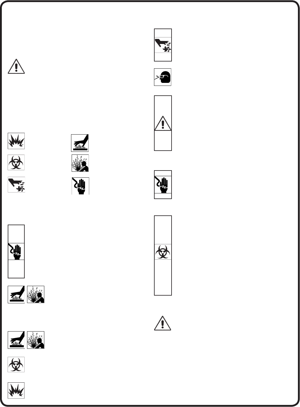
Please Read This Before Installing Or Operating Pump.
This information is provided for SAFETY and to PREVENT
EQUIPMENT PROBLEMS. To help recognize this information,
observe the following symbols:
IMPORTANT! Warns about hazards that can result
in personal injury or Indicates factors concerned with
assembly, installation, operation, or maintenance which
could result in damage to the machine or equipment if
ignored.
CAUTION! Warns about hazards that can or will cause minor
personal injury or property damage if ignored. Used with symbols
below.
WARNING! Warns about hazards that can or will cause serious
personal injury, death, or major property damage if ignored. Used
with symbols below.
Only qualifi ed personnel should install, operate and repair
pump. Any wiring of pumps should be performed by a qualifi ed
electrician.
WARNING ! To reduce risk of electrical shock, pumps and
control panels must be properly grounded in accordance
with the National Electric Code (NEC) or the Canadian
Electrical Code (CEC) and all applicable state, province,
local codes and ordinances. Improper grounding voids
warranty.
WARNING! To reduce risk of electrical shock, always
disconnect the pump from the power source before
handling or servicing. Lock out power and tag.
WARNING! Operation against a closed
discharge valve will cause premature bearing
and seal failure on any pump, and on end
suction and self priming pump the heat build
may cause the generation of steam with resulting dangerous
pressures. It is recommended that a high case temperature
switch or pressure relief valve be installed on the pump body.
CAUTION ! Pumps build up heat and pressure
during operation-allow time for pumps to cool
before handling or servicing.
WARNING ! This pump is designed to handle materials
which could cause illness or disease through direct
exposure. Wear adequate protective clothing when
working on the pump or piping.
WARNING ! Do not pump hazardous materials
(fl ammable, caustic, etc.) unless the pump is specifi cally
designed and designated to handle them.
WARNING ! Do not wear loose clothing that may
become entangled in moving parts.
WARNING ! Keep clear of suction and discharge
openings. DO NOT insert fi ngers in pump with power
connected.
Always wear eye protection when working on pumps.
Make sure lifting handles are securely fastened each
time before lifting. DO NOT operate pump without safety
devices in place. Always replace safety devices that
have been removed during service or repair. Secure the
pump in its operating position so it can not tip over, fall
or slide.
DO NOT exceed manufacturers recommendation for
maximum performance, as this could cause the motor
to overheat.
WARNING ! To reduce risk of electrical shock, all wiring
and junction connections should be made per the NEC
or CEC and applicable state or province and local
codes. Requirements may vary depending on usage
and location.
WARNING! Products returned must be cleaned,
sanitized, or decontaminated as necessary prior to
shipment, to insure that employees will not be exposed
to health hazards in handling said material. All Applicable
Laws And Regulations Shall Apply.
Bronze/brass and bronze/brass fi tted pumps may
contain lead levels higher than considered safe for
potable water systems. Lead is known to cause cancer
and birth defects or other reproductive harm. Various
government agencies have determined that leaded
copper alloys should not be used in potable water
applications. For non-leaded copper alloy materials of
construction, please contact factory.
Crane Pumps & Systems, Inc. is not responsible for
losses, injury, or death resulting from a failure to observe
these safety precautions, misuse or abuse of pumps or
equipment.
SAFETY FIRST!
Hazardous fl uids can
cause fi re or explo-
sions, burns or death
could result.
Extremely hot - Severe burns
can occur on contact.
Biohazard can cause
serious personal injury.
Hazardous fl uids can Hazard-
ous pressure, eruptions or ex-
plosions could cause personal
injury or property damage.
Rotating machinery
Amputation or severe
laceration can result.
Hazardous voltage can
shock, burn or cause death.
Other brand and product names are trademarks or registered trademarks of their respective holders.
®Burks is a registered trademark of Crane Pumps & Systems, Inc.
1994, 2001, 2003, 1/2006, 9/06 Alteration Rights Reserved

3
GENERAL INFORMATION
To the Purchaser:
Congratulations! You are the owner of one of the fi nest
pumps on the market today. Burks® Pumps are products
engineered and manufactured of high quality components.
Over eighty years of pump building experience along
with a continuing quality assurance program combine
to produce a pump which will stand up to the toughest
pumping projects.
This manual will provide helpful information concerning
installation, maintenance, and proper service guidelines.
Receiving:
Upon receiving the pump, it should be inspected for
damage or shortages. If damage has occurred, fi le a claim
immediately with the company that delivered the pump.
If the manual is removed from the crating, do not lose or
misplace.
Storage:
Short Term - Burks Pumps are manufactured for effi cient
performance following long inoperative periods in storage.
For best results, pumps can be retained in storage, as
factory assembled, in a dry atmosphere with constant
temperatures for up to six (6) months.
Long Term - Any length of time exceeding six (6) months,
but not more than twenty four (24) months. The units
should be stored in a temperature controlled area, a roofed
over walled enclosure that provides protection from the
elements (rain, snow, wind blown dust, etc..), and whose
temperature can be maintained between +40 deg. F and
+120 deg. F.
If extended high humidity is expected to be a problem, all
exposed parts should be inspected before storage and all
surfaces that have the paint scratched, damaged, or worn
should be recoated with a water base, air dry enamel paint.
All surfaces should then be sprayed with a rust-inhibiting
oil.
Service Centers:
For the location of the nearest Burks Service Center, check
your Burks representative or Crane Pumps & Systems, Inc.,
in Piqua, Ohio, telephone (937) 778-8947.
To insure safety and a successful repair, if there is
anything about the pump and motor you do not completely
understand, contact your distributor or the factory for
instructions.
WARNING ! - DO NOT work on this pump until
you are sure the pump and associated piping
are totally depressurized, and if pumping hot
liquids that the temperature is safe to handle.
WARNING ! - Be sure that electricity to the
motor is shut off and locked out, or if the
motor is to be tested while running that test
is conducted by a quali" ed person and safe
electrical procedures are followed.
WARNING ! - DO NOT start pump until it has
been " lled with water.
WIRING:
1. Motor wiring should conform to national, state and
local electrical codes.
2. Use wire of adequate size to prevent voltage drop.
3. Pump should be on a branch or separate circuit,
fused or circuit breaker, protected, with a manual
disconnect.
4. Connect the electrical supply from the switch to the
motor terminals, following the wiring diagram on the
motor nameplate or terminal cover plate.
NOTE: Be sure that the connections to the motor
terminals correspond with the voltage to be applied.
Check wiring and fuse charts before connecting wires to
service line. Make sure the voltage and frequency of the
electrical current supply agrees with that stamped on the
motor nameplate. If in doubt, check with power company.
Some pumps are equipped with three phase motors. Three
phase motors require magnetic starters, and can run in
either direction, depending on how they are connected to
the power supply.
ROTATION:
The rotation is indicated by an arrow on the casing,
and the correct rotation of three phase motors should
be established before assembling the coupling on
base mounted units. The pump should not be operated
backwards or in reverse rotation. If the motor operates in
the wrong rotation, interchange any two of the lead wires
and the correct rotation will result.
GROUNDING MOTOR:
Wiring to this pump must be installed and maintained in
accordance with the National Electrical code or your State
and local electrical code.
It is required that a permanent ground connection be made
to the unit using a conductor of appropriate size from a
metal underground water pipe or a grounded lead in the
service panel. DO NOT connect to electric power supply
until unit is permanently grounded. Connect the ground
wire to the approved ground and then connect to the
terminal provided.
IMPORTANT ! - Centrifugal pumps should
never be started or run dry. Operating a pump
dry will cause scoring of the mechanical seal,
resulting in premature seal failure. To prevent
the pump from being run dry, it should be
primed before starting.
FLOODED SUCTION PRIMING:
This method of priming a pump is relatively simple. The
liquid source is located above the pump and all that is
necessary to prime the pump is to open the air vent valve
or plug in the pump casing and to crack the gate valve in
the suction line.
4
The suction line and pump should be fi lled slowly until a
steady stream of liquid is observed fl owing from the air
vent. After the pump is operating, it is recommended that
the air vent valve or plug be opened again to insure that all
air has been expelled from the pump casing.
SUCTION LIFT PRIMING:
A foot valve should be used for priming on suction lift
applications. The foot valve, located at the end or foot of
the suction piping, functions as a check valve and allows
fl ow in one direction only, toward the pump. Otherwise, all
the liquid will drain from the pump and suction piping back
into the sump after shutdown.
Initial priming is accomplished by completely fi lling the
suction piping and pump casing with the liquid to be
pumped. This can be done by removing the air vent valve
or plug at the top of the pump casing, and inserting a
pipe nipple in the orifi ce with an appropriate increaser to
accommodate a hose connection. A priming line can also
be inserted in the discharge piping between the check
valve and the pump, or the priming can be done with a
bucket and funnel. The important thing is to completely fi ll
the suction pipe and pump casing with liquid.
When the pump is started, the vacuum created by
pumping the priming fl uid, combined with atmospheric
pressure in the liquid well, forces liquid into the suction
piping, thus opening the valve and keeping it open until
the pump is shut down. When the pump is shut down, the
liquid being pumped reverses its fl ow causing the valve to
close. The liquid is now trapped in the suction piping and
pump casing, thus maintaining a prime on the pump.
VACUUM PRIMING:
Vacuum priming consists of removing air from the pump
casing and suction piping and drawing liquid into them by
means of a vacuum creating device. The types of vacuum
equipment range from a simple hand pump to a complex
central priming system. Your specifi c priming requirements
will govern what type of vacuum primer you use.
STARTING:
For initial starting, the gate valve in the discharge line
should be closed, and opened gradually as the motor
approaches full speed, usually in fi ve to ten seconds.
After the pump has once been in operation so that the
discharge line has been completely fi lled, it is then
unnecessary to close the gate valve in starting.
SEASONAL SERVICE:
To take out of service;
1. Drain the liquid from the pump to prevent freezing and
damage to the pump body. It is recommended that a
good rust inhibitor be put into the liquid end to prevent
excessive corrosion. Keep the motor dry and covered.
2. To drain, remove the drain plug which is located below
the suction inlet of the pump. Drain the suction pipe to
a point below the frost line. All other pipes, which may
be exposed to freezing temperatures, should also be
drained.
3. Remove the priming plug. This will help the pump
body to drain by permitting air to enter the case.
To Place Pump Back into Service:
1. Replace all drain plugs previously removed, using
pipe joint compound on all male threads.
2. Make sure suction and discharge lines have been
reconnected and tightened.
3. Check to be certain that the pump shaft turns freely.
4. Verify with name plate that motor has been confi gured
for your system voltage requirements.
5. Prime and start.
DO NOT START THE PUMP UNTIL IT IS FILLED
WITH WATER.
MAINTENANCE:
The pump and its component parts that require lubrication
have been lubricated at the factory. Subsequent lubrication
depends on operating conditions. Periodic inspection of
bearing lubrication is necessary and additional grease
should be added as required on equipment supplied with
grease points.
The following lubricant is recommended:
Lubriplate 630-A or equal.
STUFFING BOX - MECHANICAL SEAL:
With the exercise of a few precautions a mechanical
seal will furnish very satisfactory operation in pumps.
Precautions which should be observed are:
1. Do not run the pump dry. The fl at faces of the seal are
lubricated by the liquid being pumped.
2. Vent the seal housing if it is the highest point in the
pump.
3. Purge the system thoroughly to remove scale or dirt
which may injure the seal prematurely due to the
abrasive condition of the liquid.
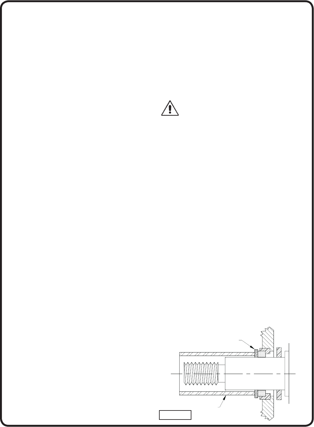
INSTALLING A NEW MECHANICAL SEAL
CAUTION: This seal is a precision product and should be
handled accordingly. Be especially careful not to scratch
or chip the lapped sealing faces of the washer and fl oating
seat. If reinstalling a used seal, both sealing faces should
be relapped.
FIGURE 1
Sleeve
Cardboard
Shipping disc
5
INSTALLING STATIONARY ELEMENT
The seat must be seated securely in the seat ring with
the lapped face out. The unlapped face is marked and
correctly assembled when shipped. Oil the seat ring with
light oil and seat it fi rmly and squarely. If this cannot be
done with the fi ngers, use a sleeve as shown in Figure 1,
inserting the cardboard shipping disc between the sleeve
and the lapped face to prevent scratching sealing face.
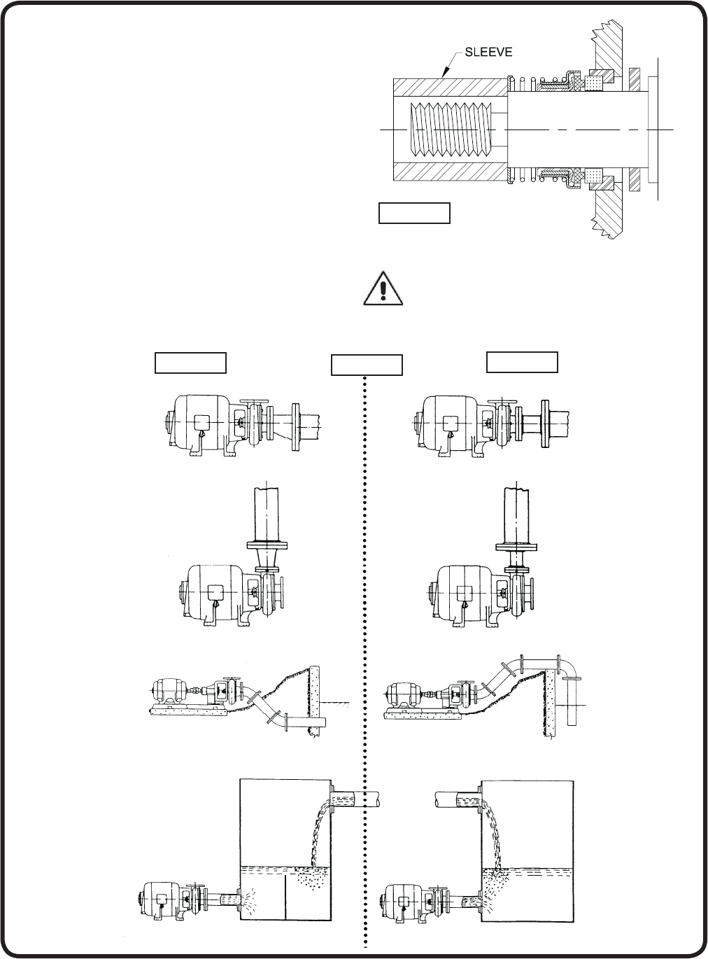
INSTALLING ROTATING ELEMENT
Oil shaft with light oil. Shaft should be clean and polished
smooth. Slide seal body on shaft (washer end fi rst) and
seat fi rmly. A sleeve as shown in Figure 2 will facilitate
this operation and prevent the rubber driving ring from
pulling out of place as the seal body is slid along the shaft.
Assembly of impeller automatically sets seal in proper
position.
Make sure at all times, and particularly before fi nal
assembly, that both sealing faces are absolutely clean.
Sealing faces should be oiled with clean, light oil.
NOTE: DO NOT use petroleum based products
to lubricate EPT or EPDM elastomers - use only
water based lubricant.
FIGURE 2
PIPING
Right Wrong

6
TROUBLE SHOOTING
CAUTION ! Always disconnect the pump from the electrical power source before handling.
If the system fails to operate properly, carefully read instructions and perform maintenance recommendations.
SYMPTOM POSSIBLE CAUSE(S)
Little or no discharge
and unit will not prime
1. Casing not fi lled with water
2. Total head too high
3. Suction head higher than pump designed for
4. Impeller partially or completely plugged
5. Hole or leak in suction line
6. Foot-valve too small
7. Impeller damaged
8. Foot-valve or suction line not submerged
deep enough in water; pulling air
9. Insuffi cient inlet pressure or suction head
10. Suction piping too small
11. Casing gasket leaking
12. Suction or discharge line valves closed
13. Piping is fouled or damaged
14. Clogged strainer or foot-valve
1. Fill pump casing. Using a foot-valve will extend
pump life and facilitate immediate priming
2. Shorten suction head
3. Lower suction head, install foot-valve and prime.
4. Disassemble pump and clean out impeller
5. Repair or replace suction line
6. Match foot-valve to piping or install one size
larger foot-valve
7. Disassemble pump and replace impeller
8. Submerge lower in water
9. Increase inlet pressure by adding more water to
tank or increasing back pressure by turning gate
valve on discharge line partially closed position
10. Increase pipe size to pump inlet size or larger
11. Replace
12. Open
13. Clean or replace
14. Clean or replace
Loss of suction after
satisfactory operation
1. Air leak in suction line
2. When unit was last turned off, water siphoned
out of pump casing
3. Suction head higher than pump designed for
4. Insuffi cient inlet pressure or suction head
5. Clogged foot-valve, strainer, or pump
6. Defective wearplate(s)
1. Repair or replace suction line
2. Refi ll (reprime) pump casing before restarting
3. Lower suction head, install foot-valve and primer
4. Increase inlet pressure by adding more water to
tank or increasing back pressure by turning gate
valve on discharge line to partially closed position.
5. Unclog, clear or replace as necessary.
6. Replace.
Pump overloads driver 1. Total head lower than pump rating, unit
delivering too much water
2. Specifi c gravity and viscosity of liquid being
pumped different than the pump rating
1. Increase back pressure on pump by turning gate
valve on discharge line to partially closed
position that will not overload motor.
2. Consult factory.
Pump vibrates and/or
makes excessive noise
1. Mounting plate or foundation not rigid enough
2. Foreign material in pump causing unbalance
3. Impeller bent
4. Cavitation present
5. Piping not supported to relieve any strain on
pump assembly
1. Reinforce.
2. Disassemble pump and remove.
3. Replace impeller.
4. Check suction line for proper size and check
valve in suction line if completely open, remove
any sharp bends before pump and shorten
suction line.
5. Make necessary adjustments.
Pump runs but no fl uid 1. Faulty suction piping (air leak)
2. Pump located too far from fl uid source
3. Gate valve closed
4. Clogged strainer
5. Fouled foot-valve
6. Discharge height too great
7. Fouled impeller
8. Faulty mechanical seal
1. Replace
2. Replace
3. Open
4. Clean or replace
5. Clean or replace
6. Lower the height
7. Clean or replace.
8. Replace
Pump leaks at shaft 1. Worn mechanical seal
2. Replacement seal not installed properly
1. Replace
2. Follow Maintenance instructions carefully
A Crane Co. Company
Limited 24 Month Warranty
Crane Pumps & Systems warrants that products of our manufacture will be free of defects in material and workmanship
under normal use and service for twenty-four (24) months after manufacture date, when installed and maintained
in accordance with our instructions.This warranty gives you speci• c legal rights, and there may also be other rights
which vary from state to state. In the event the product is covered by the Federal Consumer Product Warranties Law
(1) the duration of any implied warranties associated with the product by virtue of said law is limited to the same
duration as stated herein, (2) this warranty is a LIMITED WARRANTY, and (3) no claims of any nature whatsoever
shall be made against us, until the ultimate consumer, his successor, or assigns, noti• es us in writing of the defect,
and delivers the product and/or defective part(s) freight prepaid to our factory or nearest authorized service station.
Some states do not allow limitations on how long an implied warranty lasts, so the above limitation may not apply.
THE SOLE AND EXCLUSIVE REMEDY FOR BREACH OF ANY AND ALL WARRANTIES WITH RESPECT TO ANY
PRODUCT SHALL BE TO REPLACE OR REPAIR AT OUR ELECTION, F.O.B. POINT OF MANUFACTURE OR
AUTHORIZED REPAIR STATION, SUCH PRODUCTS AND/OR PARTS AS PROVEN DEFECTIVE. THERE SHALL BE
NO FURTHER LIABILITY, WHETHER BASED ON WARRANTY, NEGLIGENCE OR OTHERWISE. Unless expressly
stated otherwise, guarantees in the nature of performance speci• cations furnished in addition to the foregoing material
and workmanship warranties on a product manufactured by us, if any, are subject to laboratory tests corrected for
• eld performance. Any additional guarantees, in the nature of performance speci• cations must be in writing and such
writing must be signed by our authorized representative. Due to inaccuracies in • eld testing if a con! ict arises between
the results of • eld testing conducted by or for user, and laboratory tests corrected for • eld performance, the latter
shall control. RECOMMENDATIONS FOR SPECIAL APPLICATIONS OR THOSE RESULTING FROM SYSTEMS
ANALYSES AND EVALUATIONS WE CONDUCT WILL BE BASED ON OUR BEST AVAILABLE EXPERIENCE AND
PUBLISHED INDUSTRY INFORMATION. SUCH RECOMMENDATIONS DO NOT CONSTITUTE A WARRANTY OF
SATISFACTORY PERFORMANCE AND NO SUCH WARRANTY IS GIVEN.
This warranty shall not apply when damage is caused by (a) improper installation, (b) improper voltage (c) lightning
(d) excessive sand or other abrasive material (e) scale or corrosion build-up due to excessive chemical content. Any
modi• cation of the original equipment will also void the warranty. We will not be responsible for loss, damage or labor
cost due to interruption of service caused by defective parts. Neither will we accept charges incurred by others without
our prior written approval.
This warranty is void if our inspection reveals the product was used in a manner inconsistent with normal industry practice
and\or our speci• c recommendations. The purchaser is responsible for communication of all necessary information
regarding the application and use of the product. UNDER NO CIRCUMSTANCES WILL WE BE RESPONSIBLE FOR
ANY OTHER DIRECT OR CONSEQUENTIAL DAMAGES, INCLUDING BUT NOT LIMITED TO TRAVEL EXPENSES,
RENTED EQUIPMENT, OUTSIDE CONTRACTOR FEES, UNAUTHORIZED REPAIR SHOP EXPENSES, LOST
PROFITS, LOST INCOME, LABOR CHARGES, DELAYS IN PRODUCTION, IDLE PRODUCTION, WHICH DAMAGES
ARE CAUSED BY ANY DEFECTS IN MATERIAL AND\OR WORKMANSHIP AND\OR DAMAGE OR DELAYS IN
SHIPMENT. THIS WARRANTY IS EXPRESSLY IN LIEU OF ANY OTHER EXPRESS OR IMPLIED WARRANTY,
INCLUDING ANY WARRANTY OF MERCHANTABILITY OR FITNESS FOR A PARTICULAR PURPOSE.
No rights extended under this warranty shall be assigned to any other person, whether by operation of law or otherwise,
without our prior written approval.
420 Third Street 83 West Drive
Piqua, Ohio 45356 Brampton, Ont. Canada L6T 2J6
(937) 778-8947 (905) 457-6223
Fax (937) 773-7157 Fax (905) 457-2650
www.cranepumps.com

RETURNED GOODS
RETURN OF MERCHANDISE REQUIRES A “RETURNED GOODS AUTHORIZATION”.
CONTACT YOUR LOCAL CRANE PUMPS & SYSTEMS, INC. DISTRIBUTOR.
Products Returned Must Be Cleaned, Sanitized,
Or Decontaminated As Necessary Prior To Shipment,
To Insure That Employees Will Not Be Exposed To Health
Hazards In Handling Said Material. All Applicable Laws
And Regulations Shall Apply.
IMPORTANT!
WARRANTY REGISTRATION
Your product is covered by the enclosed Warranty.
To complete the Warranty Registration Form go to:
http://www.cranepumps.com/ProductRegistration/
If you have a claim under the provision of the warranty, contact your local
Crane Pumps & Systems, Inc. Distributor.

START-UP REPORT
General Information
Pump Owner’s Name: __________________________________________________________
Address: ____________________________________________________________________
Location of Installation: _________________________________________________________
Contact Person: __________________________________Phone: _______________________
Purchased From: _____________________________________________________________
Nameplate Data
Pump Model #: ___________________ Serial #: _____________________________________
Part #: __________________________ Impeller Diameter: ____________________________
Voltage: _________Phase: _____ Ø Hertz: ____________Horsepower: _______________
Full Load Amps: ___________________ Service Factor Amps: __________________________
Motor Manufacturer: ___________________________________________________________
Controls
Control panel manufacturer: _____________________________________________________
Model/Part number: ____________________________________________________________
Number of pumps operated by control panel: ________________________________________
Short circuit protection? YES___ NO___ Type: _________________________________
Number and size of short circuit device(s): ___________ Amp rating: ___________________
Overload Type: _____________ Size: ______________ Amp rating: ___________________
Do protection devices comply with pump and motor Amp rating? YES___ NO___
Are all electrical and panel entry connections tight? YES___ NO___
Is the interior of the panel dry? YES___ NO___
Liquid level Control Brand and Model: ______________________________________________
Pre-Startup
All Pumps
Type of equipment: NEW___ REBUILT___ USED___
Condition of equipment at Start-Up: DRY___ WET___ MUDDY___
Was Equipment Stored? YES___ NO___ Length of Storage: ______________________
Liquid being pumped: __________________ Liquid Temperature: _____________________
Supply Voltage/Phase/Frequency matches nameplate? YES___ NO___
Shaft turns freely? YES___ NO___
Direction of rotation verifi ed for 3Ø motors? YES___ NO___
Debris in piping or wet well? YES___ NO___
Debris removed in your presence? YES___ NO___
Pump case/wet well fi lled with liquid before startup? YES___ NO___
Is piping properly supported? YES___ NO___
Non-Submersible Pumps
Is base plate properly installed / grouted? YES___ NO___ N/A___
Coupling Alignment Verifi ed per I&O Manual? YES___ NO___ N/A___
Grease Cup/Oil Reservoir Level checked? YES___ NO___ N/A___
A Crane Co. Company

Submersible Pumps
Resistance of cable and pump motor (measured at pump control):
Red-Black:_______Ohms(•) Red-White:_______Ohms(•) White-Black:_______Ohms(•)
Resistance of Ground Circuit between Control Panel and outside of pump: __________Ohms(•)
MEG Ohms check of insulation:
Red to Ground: _________ White to Ground: __________ Black to Ground: ____________
Operational Checks
Is there noise or vibration present? YES___ NO___ Source of noise/vibration: ___________
Does check valve operate properly? YES___ NO___ N/A___
Is system free of leaks? YES___ NO___ Leaks at: ______________________________
Does system appear to operate at design ! ow rate? YES___ NO___
Nominal Voltage: _____________________ Phase: 1Ø 3Ø (select one)
Voltage Reading at panel connection, Pump OFF: L1, L2 _____ L2, L3 ____ L1, L3 _____
Voltage Reading at panel connection, Pump ON: L1, L2 ______ L2, L3 ____ L1, L3 _____
Amperage Draw, Pump ON: L1 ____________ L2 _____________ L3 _____________
Submersible Pumps
Are BAF and guide rails level / plumb? YES___ NO___
Is pump seated on discharge properly? YES___ NO___
Are level controls installed away from turbulence? YES___ NO___
Is level control operating properly? YES___ NO___
Is pump fully submerged during operation? YES___ NO___
Follow up/Corrective Action Required
YES___ NO___
Additional Comments:
____________________________________________________________________________
____________________________________________________________________________
____________________________________________________________________________
____________________________________________________________________________
____________________________________________________________________________
____________________________________________________________________________
____________________________________________________________________________
Startup performed by: _____________________ Date: ______________________________
Present at Start-Up
( ) Engineer: ____________________________ ( ) Operator: ________________________
( ) Contactor: ____________________________ ( ) Other: ___________________________
All parties should retain a copy of this report for future trouble shooting/reference
A Crane Co. Company 420 Third Street 83 West Drive
Piqua, Ohio 45356 Brampton, Ont. Canada L6T 2J6
(937) 778-8947 (905) 457-6223
Fax (937) 773-7157 Fax (905) 457-2650
www.cranepumps.com
