547761 5 Goulds Aquavar Intelligent Pump Controller Start Up Guide
547796 5 Goulds Aquavar Intelligent Pump Controller Start Up Guide 547796_5_Goulds Aquavar Intelligent Pump Controller Start Up Guide
547749 5 Goulds Aquavar Intelligent Pump Controller Start Up Guide 547749_5_Goulds Aquavar Intelligent Pump Controller Start Up Guide
547754 5 Goulds Aquavar Intelligent Pump Controller Start Up Guide 547754_5_Goulds Aquavar Intelligent Pump Controller Start Up Guide
547760 5 Goulds Aquavar Intelligent Pump Controller Start Up Guide 547760_5_Goulds Aquavar Intelligent Pump Controller Start Up Guide
547762 5 Goulds Aquavar Intelligent Pump Controller Start Up Guide 547762_5_Goulds Aquavar Intelligent Pump Controller Start Up Guide
: Pump 547761 5 Goulds Aquavar Intelligent Pump Controller Start Up Guide 547761_5_Goulds Aquavar Intelligent Pump Controller Start Up Guide pdf
Open the PDF directly: View PDF ![]() .
.
Page Count: 1
START-UP GUIDE
IM280R01
e-AB2 Packages – Aquavar IPC
Start-Up Guide
CentriPro and Aquavar are trademarks of
Xylem Inc. or one of its subsidiaries.
© 2016 Xylem Inc. IM280 Revision Number 1 September 2016
Xylem Inc.
2881 East Bayard Street Ext., Suite A, Seneca Falls, NY 13148
Phone: (800) 453-6777 Fax: (888) 322-5877
www.centripro.com
Technical Hotline (866) 673-0445
• Aquavar IPC controller will be factory programmed with
the following preset conditions:
• Motor characteristics matched to e-AB2 pump/
motor assembly – horsepower, voltage, frequency,
nominal motor speed, full load amps, surface motor
type, sleep frequency of 30 Hz, single pump system,
constant pressure application and PSI units for
pressure feedback.
• Default set pressure of 50 PSI
• Analog A53 switch terminal set for use with 4-20 mA
Pressure Transducer (0-300 psi);
• Pressure transducer cable to be installed in A53 and
D12 terminals (page 34 of IM255)
• Jumpers installed
– D13 and D18 – Start / Stop - closed
– D29 and D32 – No Water / Loss of Prime Restart
• Note that the Aquavar IPC used within e-AB2 booster
packages are sized to have single phase 230v input
power with three phase output power to the motor.
Single Phase 230v power source to be connected to L1
and L2.
• Check Pump and Motor Rotation by selecting Hand On.
If motor is running backwards, power down drive, wait
ve minutes, and rotate motor wires. Once rotation is
veried, select Off.
• Pressure Adjustment – Factory Default Value 50 PSI
• Choose: Quick Menu
• Screen will show: Q1: My Personal Menu; Select OK
• Screen will show Parameter number 20-21: Set
point; Select OK
• Using Up / Down Arrows adjust Set Pressure
accordingly. Select OK
• Press Status to return to Main Menu display
• For Duplex Operation refer to Aquavar IPC – Literature
section within www.goulds.com
• Duplex harness cable part 9K706 (3 feet) or 9K707
(6 feet)
• For additional detail of Aquavar IPC programming –
refer to IM255
Relay 02 Terminal number 4–6 (break), 4–5 (make)
Maximum terminal load (AC-2)1 on 4–5 (NO) (resistive load)2,3 400 V AC, 2A
Maximum terminal load (AC-15)1 (Inductive load @ cosφ 0.4) 240 V AC, 0.2A
Maximum terminal load (DC-1)1 on 4–5 (NO) (Resistive load) 80 V DC, 2A
Maximum terminal load (DC-13)1 on 4–5 (NO) (Inductive load) 24 V DC, 0.1A
Maximum terminal load (AC-1)1 on 4–6 (NC) (Resistive load) 240 V AC, 2A
Maximum terminal load (AC-15)1 on 4–6 (NC) (Inductive load @ cosφ
0.4)
240 V AC, 0.2A
Maximum terminal load (DC-1)1 on 4–6 (NC) (Resistive load) 50 V DC, 2A
Maximum terminal load (DC-13)1 on 4–6 (NC) (Inductive load) 24 V DC, 0.1A
Minimum terminal load on 1–3 (NC), 1–2 (NO), 4–6 (NC), 4–5 (NO) 24 V DC 10mA, 24 V AC 20mA
Environment according to EN 60664–1 overvoltage category III/pollution degree 2
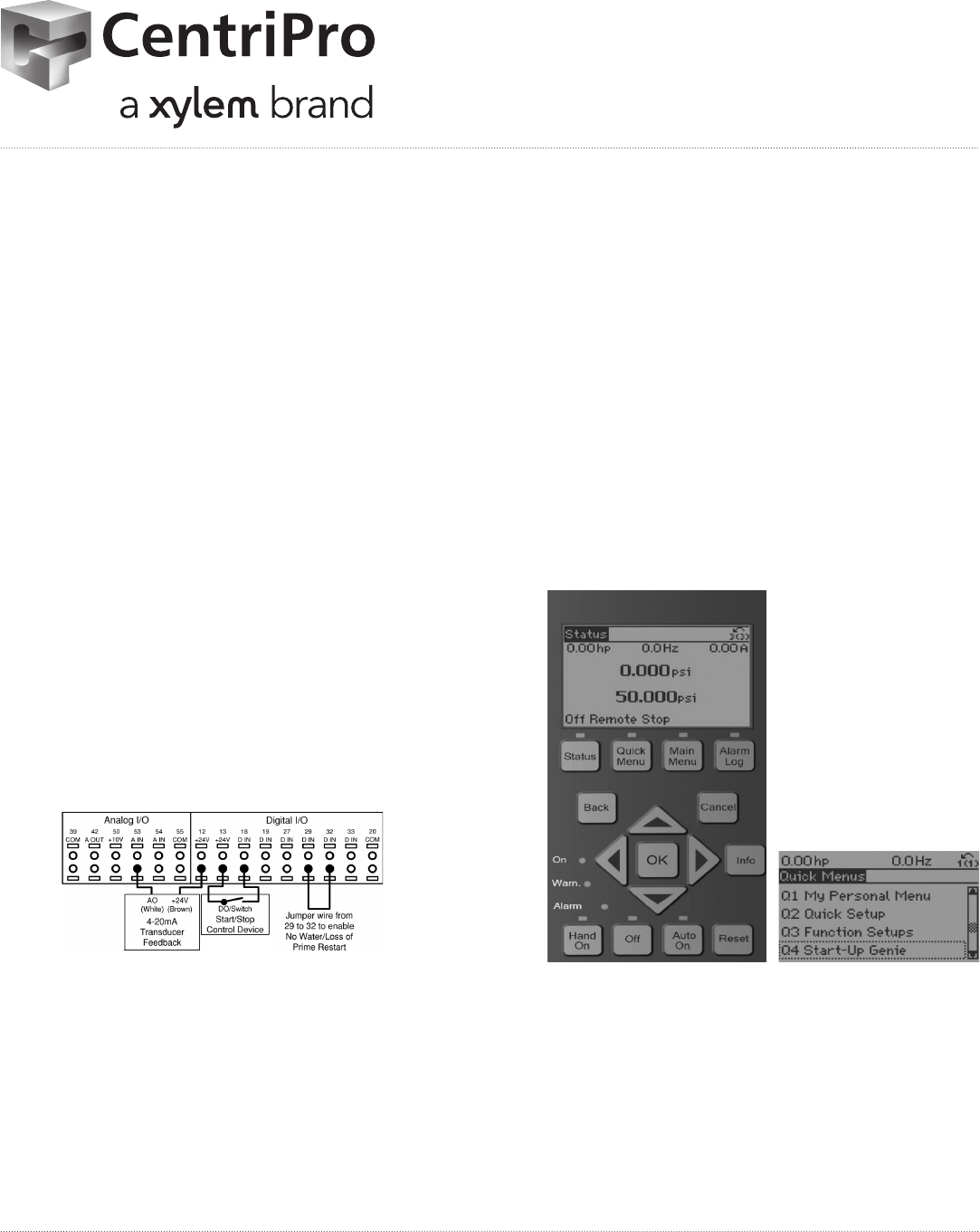
Wiring for factory default setup
This configuration utilizes the controller factory default settings for I/O. The factory default
settings are configured for a single pump, constant pressure application with a 300 psi,
4-20mA pressure transducer wired to AI 53. A jumper wire is needed between terminals
29 and 32 to enable the No Water/Loss of Prime Restart function. A Start signal is applied
on Digital Input 18. The controller will receive a Start command when DI 18 is connected
to 24V. There are no parameters that need to be adjusted for this configuration. Refer to
Commissioning section for details on configuring the controller and changing application
settings.
CAUTION:
When a Start (Closed) signal is present on DI18, the controller can start the pump/motor
at any time without warning. Set DI18 to Stop (Open) or press the [Off] operation key
before using the Genie. Apply the Start signal to the controller only when pump/motor
operation is desired.
NOTICE:
The factory default settings are configured to require a start signal wired to DI18 as shown
below.
Figure 19: Required terminal connections for use with factory default settings
Pump protect
A Pump Protect function can be used to turn off the controller and issue an alarm (Pump
Protect Alarm 60) when system pressures, temperatures, levels, etc. are outside of the
normal operating range for the system. The Pump Protect function can be configured on
digital input 19 and digital input 27. These inputs can be controlled by an external device
such as a suction pressure switch, an over pressure switch, a temperature switch, a
differential pressure switch, etc. The device chosen should be normally closed. The
[22-00] Pump Protect Delay parameter can be configured to delay the onset of the Pump
Electrical Installation
34 Aquavar® Intelligent Pump Controller INSTRUCTION MANUAL
