548671 1 Goulds Quick Disconnect Control Box Brochure
: Pump 548671 1 Goulds Quick Disconnect Control Box Brochure 548671_1_Goulds Quick Disconnect Control Box Brochure pdf
Open the PDF directly: View PDF ![]() .
.
Page Count: 4
TESTED TO UL AND CSA STANDARDS BY UL.
UL
®
CUS
FEATURES
Voltage Relays for installer convenience
115 and 230 volt models
208 volt relay available for low voltage applications
Start Capacitors with resistors
NEMA 3R enclosure for indoor or outdoor mounting
Quick disconnect cover design will retrot with other
Q-D control boxes
Multiple knockouts
Two grounding lugs
AGENCY LISTINGS
Quick Disconnect
Control Boxes
FOR 4", 1Ø, 3-WIRE SUBMERSIBLE MOTORS
TECHNICAL BROCHURE
BCQD R2
PAGE 2
Residential Water Systems
CentriPro
“K” REPAIR PARTS FOR QUICK DISCONNECT STYLE CONTROL BOXES*
CENTRIPRO ORDER NUMBERS
First Design
Tab Down ➀
Current Design
Tab Up ➁
Control Box
Order
Number
HP KW Volts Replaces
old #
May
Replace
FE #
Standard
Circuit
Breaker
Standard
Fuse
Dual Element
Time Delay
Fuse
Enclosure
Dimensions
W x D x H (in)
Shipping
Wt. (lbs)
CB05411 .5 .37 115 00043 280 104 49 30 A 35 A 20 A 4.8 x 2.9 x 8.4 4
CB05412 .5 .37 230 00044 280 105 49 15 A 20 A 10 A 4.8 x 2.9 x 8.4 4
CB07412 .75 .55 230 00054 280 107 49 20 A 25 A 15 A 4.8 x 2.9 x 8.4 4
CB10412 1 .75 230 00064 280 108 49 25 A 30 A 20 A 4.8 x 2.9 x 8.4 4
CentriPro
Control Box
Order Number
HP Volts
Capacitor
Repair Part
Order Number
Start
Capacitor
Mfd.
Capacitor
Voltage
Capacitor
Quantity
Start Relay
Order Number
CB05411 .5 115 9K450 250-300 125
1
➀ 9K457
➁ 9K566
CB05412
230
9K448 59-71
250 ➀ 9K462
➁ 9K567
CB07412 .75 9K449 86-103
CB10412 1 9K447 105-126
* Repair parts above will work in new voltage relay control boxes as well as in control boxes shown in "Replaces Column" above.
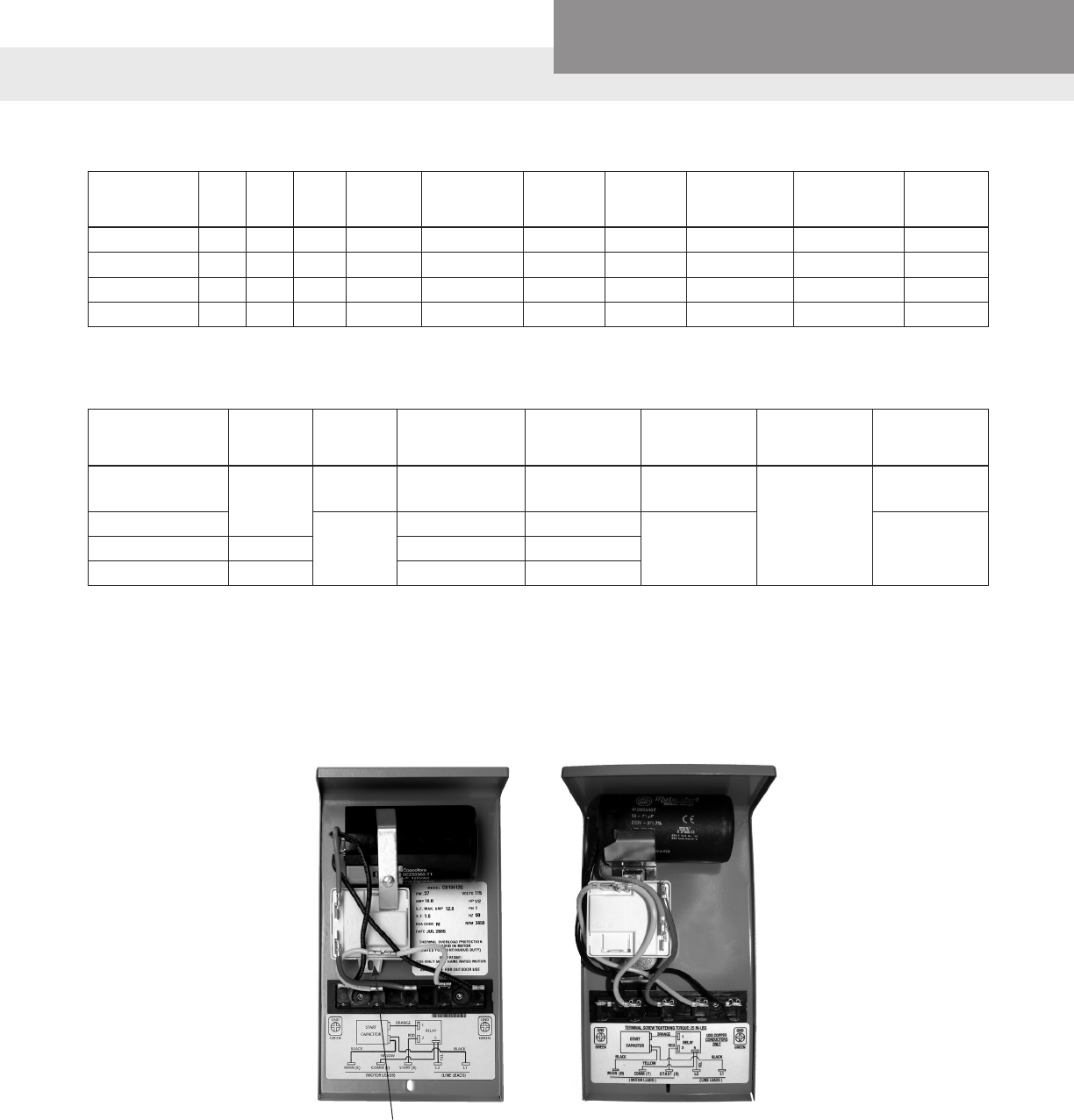
➀ First Design - Up to June 2009 - Relay tab on bottom, capacitor held by bracket and screw. See pictures below. 208 V use 9K461 relay.
➁ Current Design - Starting June 2009 - Relay tab on top and capacitors, all held by one screw. See pictures below. The relays are designed
for operation in a specic orientation, therefore there are two different numbers now. 208 V use 9K568 relay.
PAGE 3
Residential Water Systems
CentriPro
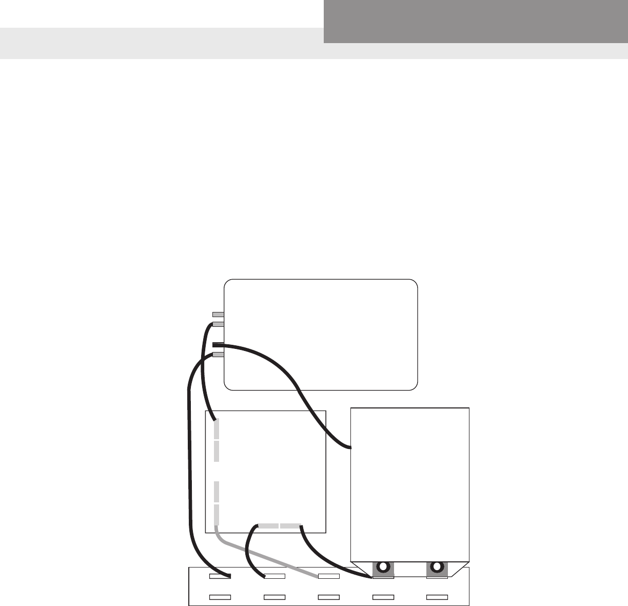
INSTALLING A PumpSaver® INSIDER
1. Remove the cover from the front of the 3-wire CentriPro® control box.
2. Remove the yellow wire from the terminal strip at L2.
3. Remove the black wire from L1 to the capacitor.
4. Press the PumpSaver onto the L1 and L2 terminals.
5. Reconnect the yellow wire to L2 on the PumpSaver.
6. Connect the blue wire attached to the PumpSaver to the dual-lug terminal (with the black wire) of the ca-
pacitor.
ORANGE
BLUE
BLK VOLTAGE
RELAY
1
2
5
YEL
YEL
RED
B(MAIN) Y(COMM) R(START)L
2L
1
MODEL 111/231
INSIDER
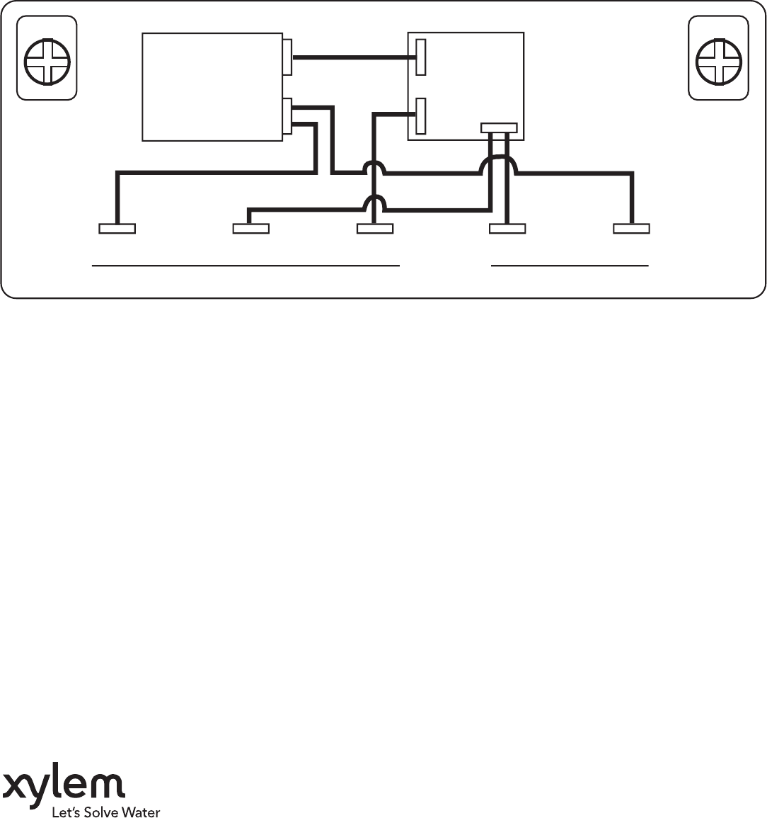
WIRING DIAGRAM
GND
GREEN
GND
GREEN
BLACK BLACK
START
CAPACITOR
RELAY
ORANGE
RED
YELLOW
MAIN (B) COMM (Y) START (R) L2 L1
1
25
YEL.
(MOTOR LEADS) (LINE LEADS)
Xylem Inc.
2881 East Bayard Street Ext., Suite A
Seneca Falls, NY 13148
Phone: (866) 325-4210
Fax: (888) 322-5877
www.centripro.com
CentriPro is a trademark of Xylem Inc. or one of its subsidiaries.
PumpSaver is a registered trademark of SymCom, Inc.
© 2012 Xylem Inc. BCQD R2 March 2014
