This Manual Is For DARLEY CHAMPION FIRE PUMP 550848 2 2BEF BS Porpoise Floating Operation Instructions
: Pump 550848 2 Darley 2Bef-Bs Porpoise Floating Pump Operation Instructions 550848_2_Darley 2BEF-BS Porpoise Floating Pump Operation Instructions pdf
Open the PDF directly: View PDF ![]() .
.
Page Count: 28
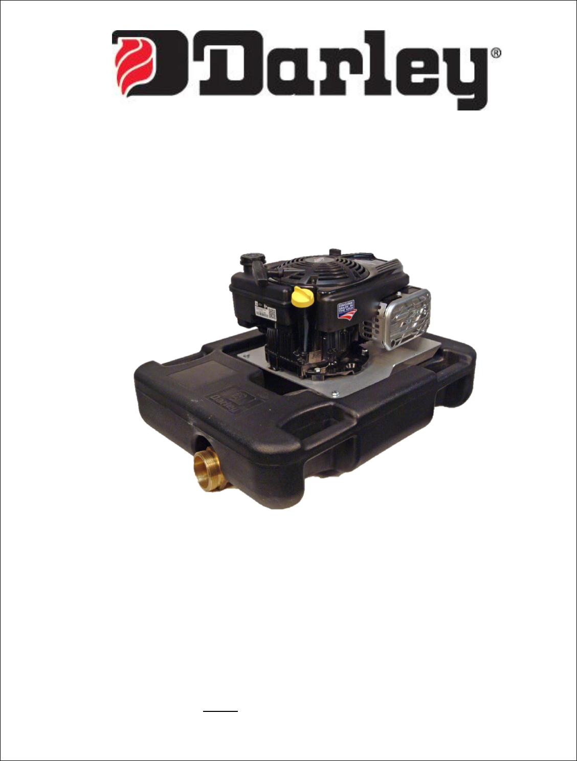
OPERATING INSTRUCTIONS
2BEF PORPOISE FLOAT PUMP
Corporate Office: Pump Manufacturing: Apparatus Division:
325 Spring Lake Drive 1051 Palmer St. 920 Kurth Rd.
Itasca, Illinois 60143-2072 Chippewa Falls, WI 54729 Chippewa Falls, WI 54729
800-323-0244, fax (708) 345-8993 800-634-7812, Fax (715) 726-2656 800-527-0068, Fax 726-2648
WWW.DARLEY.COM
This manual is for DARLEY FIRE PUMP:
Model: 2BEF Pump Serial Number: _____________


Introduction
Included in this manual is information for the correct operation, maintenance, troubleshooting,
definition of terms and contacts for the Darley 2BEF Porpoise Float Pump. Please read and
understand these instructions thoroughly before putting this system into service. Doing so will
ensure optimum performance and long life of your Darley Floating Pump.
This manual is divided into eight sections, each section details an important portion of this
manual and pump.
Section 1 Definition of Symbols
Section 2 Operation
Section 3 Pump Assembly/Disassembly
Section 4 Components
Section 5 Maintenance Schedule
Section 6 Troubleshooting
Section 7 Definition of Terms and Operating Characteristics of
Pumps.
Section 8 Contacts

Prepared by: TED Rev. 0
Approved by: AAN 1 Date: 06/29/15
Revised by: Rev. Date:
1200661
Section 1
Definition of Symbols

Prepared by: TED Rev. 0
Approved by: AAN 2 Date: 06/29/15
Revised by: Rev. Date:
1200661
IMPORTANT
Throughout this manual you will find Caution, Warning and Danger
symbols. Please pay close attention to these symbols as they are for your
safety.
- Signifies an imminently hazardous situation that
could result in death or serious injury.
- Signifies a potentially hazardous situation that could
result in death or serious injury.
- Signifies a potentially hazardous situation that could
result in minor or moderate injury.
- Signifies a potentially hazardous situation that could
result in property damage.
Intentionally ignoring any of these identified hazards is not
recommended. W.S. Darley does not advise such actions or take
responsibility for the actions of any operator of this unit.
Prepared by: TED Rev. 0
Approved by: AAN 3 Date: 06/29/15
Revised by: Rev. Date:
1200661
Section 2
Operation

Prepared by: TED Rev. 0
Approved by: AAN 4 Date: 06/29/15
Revised by: Rev. Date:
1200661
Operating Instructions
For Darley “PORPOISE” Floating Fire Pump
Do not use this pump for hose testing. Such testing could
result in major pump or engine damage. Such damage may cause
overheating of the engine and/or pump and bodily harm.
PREPARATIONS FOR PUMPING
Make sure to read the engine instruction manual before use.
Check the engine oil level before starting the engine.
Check the fuel level before starting the engine.
This pump is equipped with a mechanical seal. Do not run the pump dry or at
high speed unless it is placed in water of adequate depth.
Connect the discharge hose to the pump.
Start the engine.
Place float pump in the water immediately after starting. This Float pump is self-
priming due to a flooded suction. The pump will prime more quickly if the engine
is run at lower speeds until fully primed.
Slowly open the engine throttle once the pump is primed and discharging water.
Recommendations
Do not allow unusual elevation of the discharge hose, this may
cause the float to overturn.
When pumping dirty water, flush pump with clean water after usage.

Prepared by: TED Rev. 0
Approved by: AAN 5 Date: 06/29/15
Revised by: Rev. Date:
1200661
Section 3
Maintenance (Assembly/Disassembly)
Prepared by: TED Rev. 0
Approved by: AAN 6 Date: 06/29/15
Revised by: Rev. Date:
1200661
PUMP DISASSEMBLY
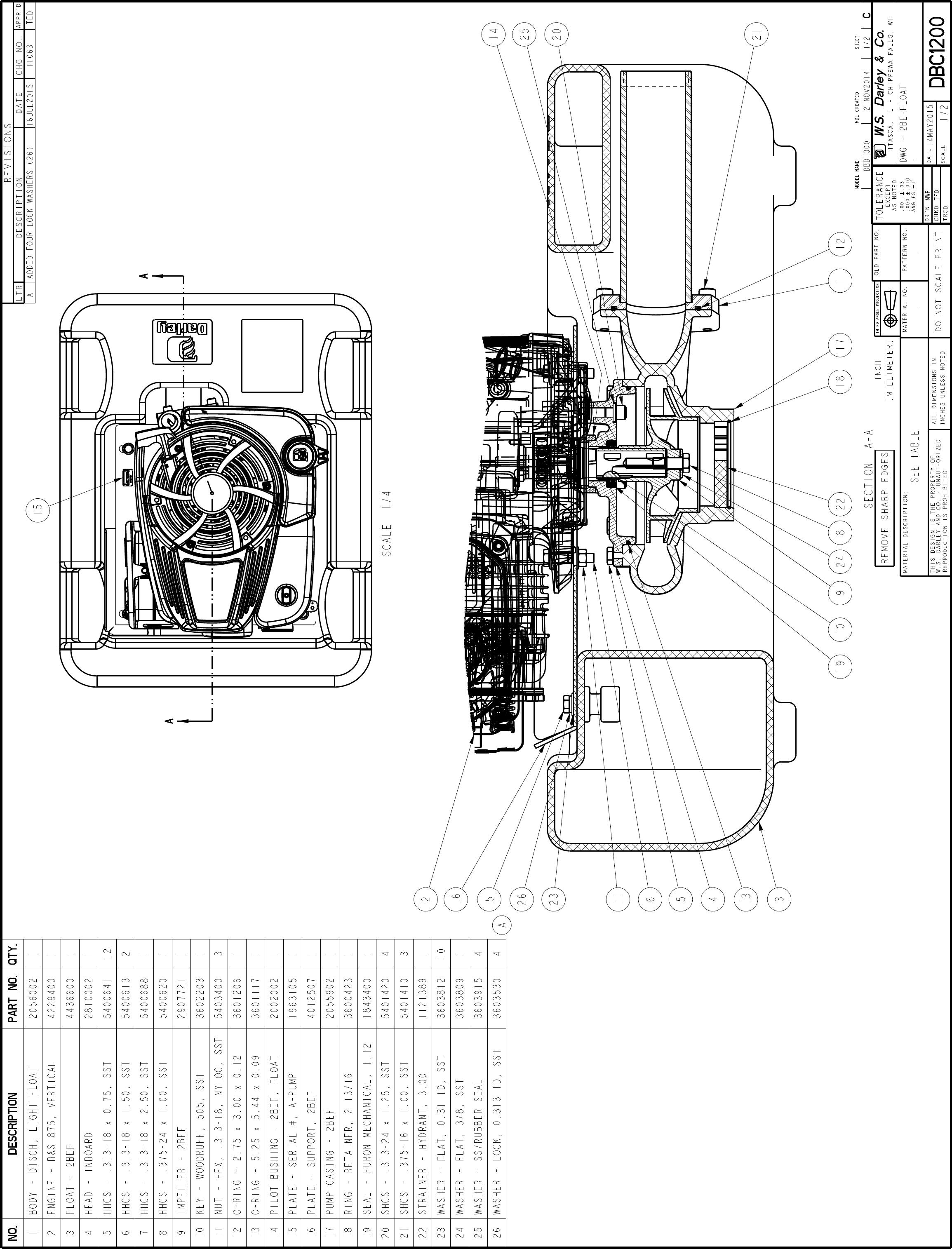
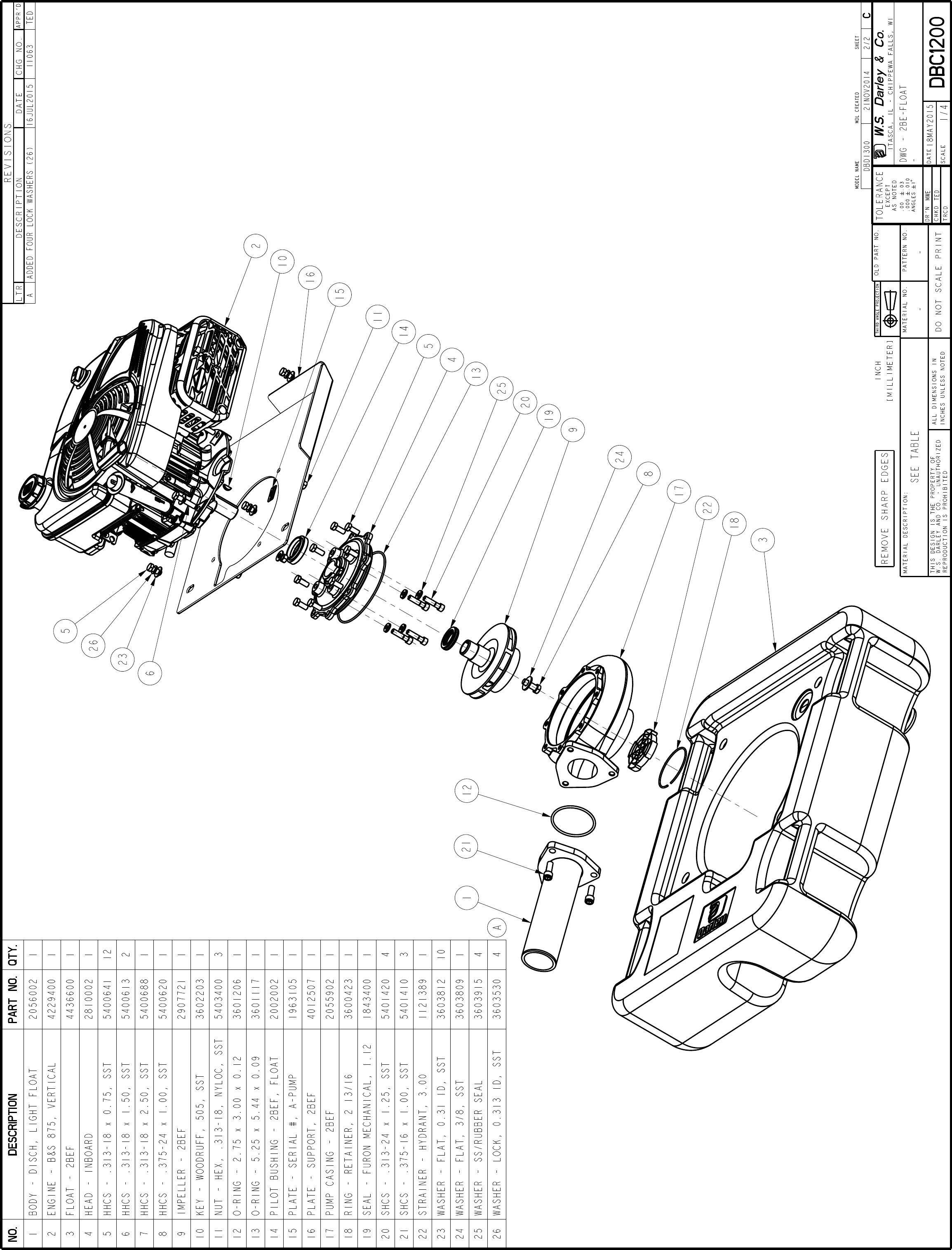
Drawing DBC1200
For pump overhaul or disassembly follow the corresponding steps
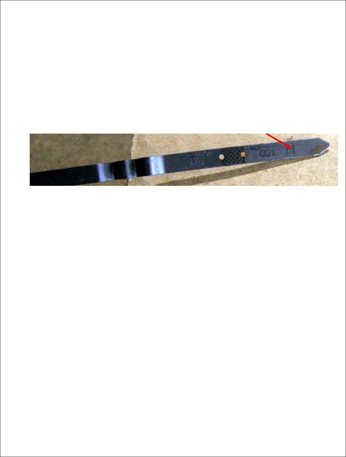
Drain oil and gas from engine (2), ensuring there is no fuel in the tank or lines.
o There may be small residual amounts of oil remaining in the engine (up to 2
ounces), which may read at the very end of the dipstick (see photo below).
If the oil level is up as high as the H on the dipstick, below the ADD mark,
the oil needs to be further drained prior to tipping the engine for removal
from the float.
Remove the four cap screws holding the support plate (16) to the float (3).
Remove the engine and pump by tilting the engine forward and lifting the
assembly clear of the float.
Remove the pump discharge (1) from the pump casing (17) by removing the three
socket head cap screws (21).
The pump casing (17) may now be removed from inboard head (4) by removing
the eight hex headed cap screws (5). Gentle tapping with a rubber mallet may be
necessary to free the pump casing from the inboard head, after all eight cap
screws are removed.
Remove the impeller bolt (8). Use a strap wrench to prevent impeller (9) rotation
and ease removal of the impeller bolt (8).
Remove impeller (9) by threading a 1/2-13 NC x 1 3/4 pusher bolt into the tapped
hole occupied by the impeller bolt. Do not force impeller, use penetrating oil on
the engine shaft if the impeller will not move.
The mechanical seal (19) may be inspected and replaced if necessary when the
impeller is removed. The inboard head (4) should be removed only if necessary.
If necessary to remove the inboard head (4), remove the four 5/16 socket head
cap screws (20) and sealing washers (25). Note: These washers are one time use,

Prepared by: TED Rev. 0
Approved by: AAN 7 Date: 06/29/15
Revised by: Rev. Date:
1200661
and will require replacement when removed. Be cautions to avoid losing the pilot
bushing (14).
Inspect o-ring (13), and replace as necessary.
Inspect and replace worn or damaged parts. If you are unsure if a part is damaged
or worn contact Darley Customer Service for assistance.
Parts Inspection and Measurement
Clean all parts and examine carefully for wear or deterioration. Replace any
questionable parts.
Use only stainless steel when replacing any fasteners, or washers.
Inspect the impeller hub seal area (9) for grooves, pits, and scratches in the seal
area. Replace if damaged or worn.
Measure the impeller seal ring (9) and stationary seal ring area of the pump casing
(17) for wear. Use the following table for comparison:
Original impeller seal ring O.D. (9) ----------------------- 3.300/3.298”
Original pump casing seal ring I.D. (17) ----------------- 3.316/3.314”
Original diametral clearance -------------------------------- .018/.014”
Maximum allowable diametral clearance ------------------ .025”
For pump re-assembly follow the corresponding steps
Drawing DBC1200
Use Loctite 242/243 (Blue) thread locker or equivalent on all pump related
fasteners.
Ensure that the engine is drained of all gas and oil.
If the mounting plate (16) is not already attached to the engine, it must be
installed onto the bottom of the engine using Stainless Steel – HHCS (6 & 7) and
Stainless Steel Nyloc nuts (11).
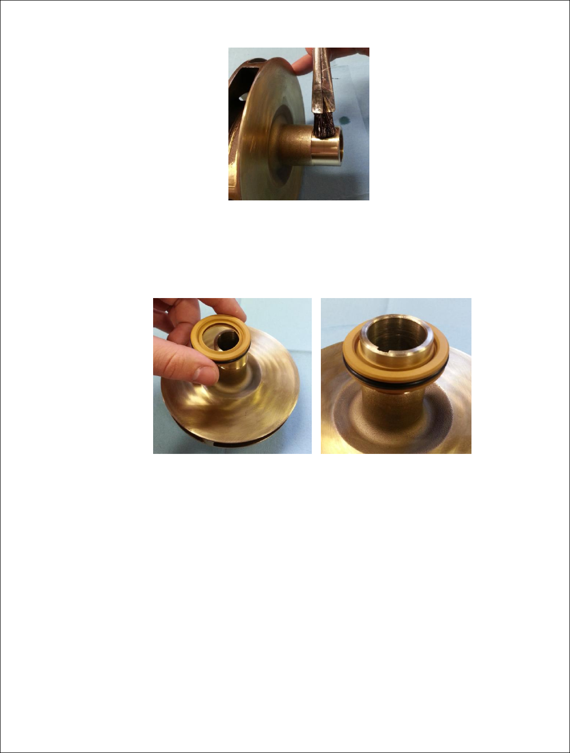
If the mechanical seal is being replaced, pre-form the lips of the seal as follows
(see photo below):
Prepared by: TED Rev. 0
Approved by: AAN 8 Date: 06/29/15
Revised by: Rev. Date:
1200661
o Apply a thin coating of oil onto the impeller hub (9)
o Slide the seal (19) onto the impeller hub (9) so that the lips are facing away
from the impeller (this is reversed from normal operating direction)
o The seal (19) must be on the impeller hub (9) in this orientation for a
minimum of 2 minutes, allowing the lips to take shape. Only remove the
seal from the sleeve when ready to be installed into the pump casing.
In the woodruff keyway closest to the engine, install the #505 stainless steel
woodruff drive key (10) into the engine shaft.
If the inboard head (4) was removed, re-install the pump pilot bushing (14) and
attach the head to the engine using the four new sealing washers (25) and socket
head cap screws (20) torqued evenly to 100 in-lbs using an alternating opposite
corner pattern. DO NOT OVER TIGHTEN.
Lightly oil the mechanical seal bore inside of the inboard head (4).
Apply a light coat of light weight grease or Never Seize to the engine shaft.
Prepared by: TED Rev. 0
Approved by: AAN 9 Date: 06/29/15
Revised by: Rev. Date:
1200661
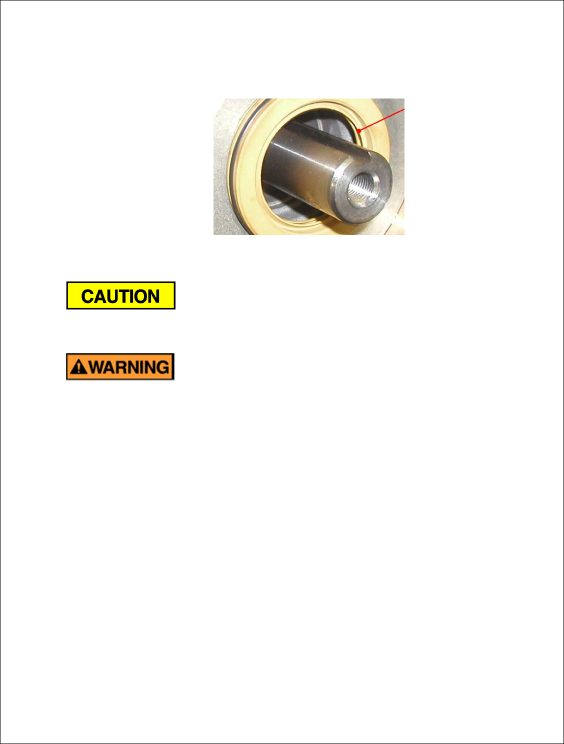
Remove the shaft seal (19) from the impeller hub (9), and using a pusher tool (PVC
tubing of a close diameter in relation to the seal, or a ¾” PVC coupling), push the
mechanical seal into its pocket in the inboard head (4), with the LIPS CURLING
AWAY from the engine (see photo below).
Slide the impeller (9) onto the shaft, being careful not to roll the lips of the
mechanical seal (19) backwards.
If care is not exercised when installing the mechanical seal and it
is damaged, the pump will not perform to full efficiency, and water may be forced
into the engine.
Ensure that the spark plug wire is removed from the engine spark
plug. This will prevent the engine from starting if the engine shaft rotates.
Install the stainless steel impeller washer (24) and 3/8-24 x 1.00 lg. stainless steel
HHCS (8) with a small drop of Loctite 242/243 (Blue) thread locker to hold the
impeller (9) in place. Ensure that the spark plug wire is removed from the engine
spark plug. This will prevent the engine from starting if the engine shaft rotates.
Using the o-ring (13) with a very thin film of silicone based grease to seal the
flange, install the pump casing (17) onto the inboard head (4) with six 3/8-16 x
0.75 lg HHCS (5) with a small drop of Loctite 242/243 (Blue) thread locker on each.
The discharge flange of the pump casing will be located below the engine oil
dipstick.
Pull the recoil rope two or three times, to ensure that the pump assembly and
engine are aligned.
Reinstall the spark plug wire.
Prepared by: TED Rev. 0
Approved by: AAN 10 Date: 06/29/15
Revised by: Rev. Date:
1200661
Using o-ring (12) with a very thin film of silicone based grease to seal the flange,
install the discharge (1) to the discharge flange of the pump casing (17) with three
3/8-16 x 1.25 lg. SHCS (21) with a small drop of Loctite 242/243 (Blue) thread
locker.
Install the suction strainer (22) into the suction of the pump casing (17). Retainer
ring (18) is used to hold the strainer in place. The retainer ring may need to be
slightly expanded to achieve a tight fit in the groove in the pump casing.
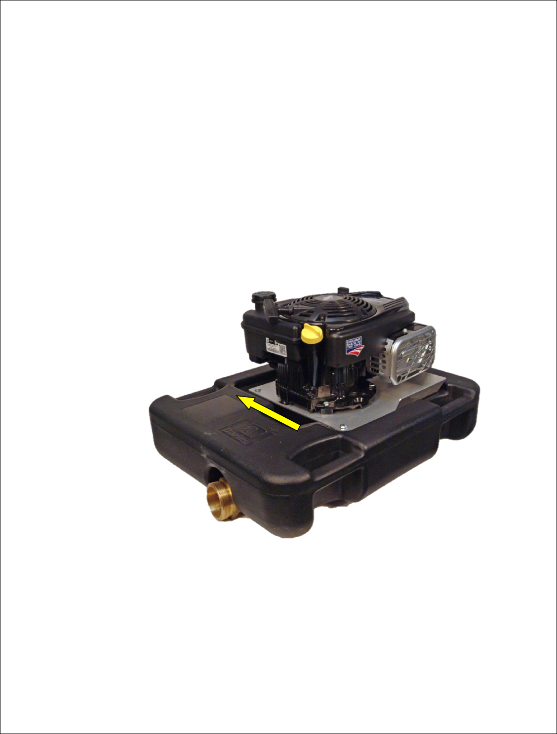
Set the pump assembly into the float (3). Using the slots in the mounting plate
(16), slide the pump assembly as far towards the fuel tank side as possible before
tightening the four fasteners (see photo below). Final balance can be checked by
placing the pump assembly into water and adjusting the pump from side to side
on the float. Using four 5/16 flat washers (23), lock washers, and 5/16 x 0.75 lg
HHCS (5), fasten the mounting plate (16) to the float. DO NOT OVER TIGHTEN. DO
NOT USE THREAD LOCKER.
APPR'D
CHG NO.DATEDESCRIPTIONLTR
REVISIONS
DO NOT SCALE PRINT
INCHES UNLESS NOTED
ALL DIMENSIONS IN
REPRODUCTION IS PROHIBITED
W.S. DARLEY AND CO. - UNAUTHORIZED
THIS DESIGN IS THE PROPERTY OF
MATERIAL DESCRIPTION: PATTERN NO.MATERIAL NO.
OLD PART NO.
INCH
THIRD ANGLE PROJECTION
DATE
SCALE
CHKD
DR'N
TRCD
EXCEPT
AS NOTED
.00 .03
.000 .010
ANGLES
1
TOLERANCE
ITASCA, IL - CHIPPEWA FALLS, WI
W.S. Darley & Co.
[MILLIMETER]
REMOVE SHARP EDGES
MODEL NAME SHEETMDL CREATED
SEE TABLE - -
MWE
TED
DWG - 2BE-FLOAT
-
14MAY2015 DBC1200
1/2
DBD1300 21NOV2014 1/2 C
NO. DESCRIPTION PART NO. QTY.
1 BODY - DISCH, LIGHT FLOAT 2056002 1
2 ENGINE - B&S 875, VERTICAL 4229400 1
3 FLOAT - 2BEF 4436600 1
4 HEAD - INBOARD 2810002 1
5 HHCS - .313-18 x 0.75, SST 5400641 12
6 HHCS - .313-18 x 1.50, SST 5400613 2
7 HHCS - .313-18 x 2.50, SST 5400688 1
8 HHCS - .375-24 x 1.00, SST 5400620 1
9 IMPELLER - 2BEF 2907721 1
10 KEY - WOODRUFF, 505, SST 3602203 1
11 NUT - HEX, .313-18, NYLOC, SST 5403400 3
12 O-RING - 2.75 x 3.00 x 0.12 3601206 1
13 O-RING - 5.25 x 5.44 x 0.09 3601117 1
14 PILOT BUSHING - 2BEF, FLOAT 2002002 1
15 PLATE - SERIAL #, A-PUMP 1963105 1
16 PLATE - SUPPORT, 2BEF 4012507 1
17 PUMP CASING - 2BEF 2055902 1
18 RING - RETAINER, 2 13/16 3600423 1
19 SEAL - FURON MECHANICAL, 1.12 1843400 1
20 SHCS - .313-24 x 1.25, SST 5401420 4
21 SHCS - .375-16 x 1.00, SST 5401410 3
22 STRAINER - HYDRANT, 3.00 1121389 1
23 WASHER - FLAT, 0.31 ID, SST 3603812 10
24 WASHER - FLAT, 3/8, SST 3603809 1
25 WASHER - SS/RUBBER SEAL 3603915 4
26 WASHER - LOCK, 0.313 ID, SST 3603530 4
A ADDED FOUR LOCK WASHERS (26) 16JUL2015 11063 TED
A
SECTION A-A
1
2
3
4
5
6
8 9 10
11
12
13
14
16
17 18 19
20
21
22
23
25
5
24
26
15
SCALE 1/4
32
32
32
32
APPR'D
CHG NO.DATEDESCRIPTIONLTR
REVISIONS
DO NOT SCALE PRINT
INCHES UNLESS NOTED
ALL DIMENSIONS IN
REPRODUCTION IS PROHIBITED
W.S. DARLEY AND CO. - UNAUTHORIZED
THIS DESIGN IS THE PROPERTY OF
MATERIAL DESCRIPTION: PATTERN NO.MATERIAL NO.
OLD PART NO.
INCH
THIRD ANGLE PROJECTION
DATE
SCALE
CHKD
DR'N
TRCD
EXCEPT
AS NOTED
.00 .03
.000 .010
ANGLES
1
TOLERANCE
ITASCA, IL - CHIPPEWA FALLS, WI
W.S. Darley & Co.
[MILLIMETER]
REMOVE SHARP EDGES
MODEL NAME SHEETMDL CREATED
SEE TABLE - -
MWE
TED
DWG - 2BE-FLOAT
-
18MAY2015 DBC1200
1/4
DBD1300 21NOV2014 2/2 C
NO. DESCRIPTION PART NO. QTY.
1 BODY - DISCH, LIGHT FLOAT 2056002 1
2 ENGINE - B&S 875, VERTICAL 4229400 1
3 FLOAT - 2BEF 4436600 1
4 HEAD - INBOARD 2810002 1
5 HHCS - .313-18 x 0.75, SST 5400641 12
6 HHCS - .313-18 x 1.50, SST 5400613 2
7 HHCS - .313-18 x 2.50, SST 5400688 1
8 HHCS - .375-24 x 1.00, SST 5400620 1
9 IMPELLER - 2BEF 2907721 1
10 KEY - WOODRUFF, 505, SST 3602203 1
11 NUT - HEX, .313-18, NYLOC, SST 5403400 3
12 O-RING - 2.75 x 3.00 x 0.12 3601206 1
13 O-RING - 5.25 x 5.44 x 0.09 3601117 1
14 PILOT BUSHING - 2BEF, FLOAT 2002002 1
15 PLATE - SERIAL #, A-PUMP 1963105 1
16 PLATE - SUPPORT, 2BEF 4012507 1
17 PUMP CASING - 2BEF 2055902 1
18 RING - RETAINER, 2 13/16 3600423 1
19 SEAL - FURON MECHANICAL, 1.12 1843400 1
20 SHCS - .313-24 x 1.25, SST 5401420 4
21 SHCS - .375-16 x 1.00, SST 5401410 3
22 STRAINER - HYDRANT, 3.00 1121389 1
23 WASHER - FLAT, 0.31 ID, SST 3603812 10
24 WASHER - FLAT, 3/8, SST 3603809 1
25 WASHER - SS/RUBBER SEAL 3603915 4
26 WASHER - LOCK, 0.313 ID, SST 3603530 4
A ADDED FOUR LOCK WASHERS (26) 16JUL2015 11063 TED
A
1
2
3
4
5
6
8
9
10
11
12 13
14
15
16
17
18
19
20
21
22
23
24
25
26
5
APPR'D
CHG NO.DATEDESCRIPTIONLTR
REVISIONS
DO NOT SCALE PRINT
INCHES UNLESS NOTED
ALL DIMENSIONS IN
REPRODUCTION IS PROHIBITED
W.S. DARLEY AND CO. - UNAUTHORIZED
THIS DESIGN IS THE PROPERTY OF
MATERIAL DESCRIPTION: PATTERN NO.MATERIAL NO.
OLD PART NO.
INCH
THIRD ANGLE PROJECTION
DATE
SCALE
CHKD
DR'N
TRCD
EXCEPT
AS NOTED
.00 .03
.000 .010
ANGLES
1
TOLERANCE
ITASCA, IL - CHIPPEWA FALLS, WI
W.S. Darley
& Co.
[MILLIMETER]
REMOVE SHARP EDGES
MDL CREATED SHEET
MODEL NAME
16.99
431,6[ ]
2.00
50,8[ ]
18.75
476,3[ ] 11.50
292,1[ ]
.75
19,1[ ]
8.38
212,7[ ]
21.00
533,4[ ]
26.50
673,1[ ]
DWG - 2BE-FLOAT
-
07-Apr-15 DBD1300
1/4
TED
AAN
DBD1300 21NOV2014 1/1 D
-- -
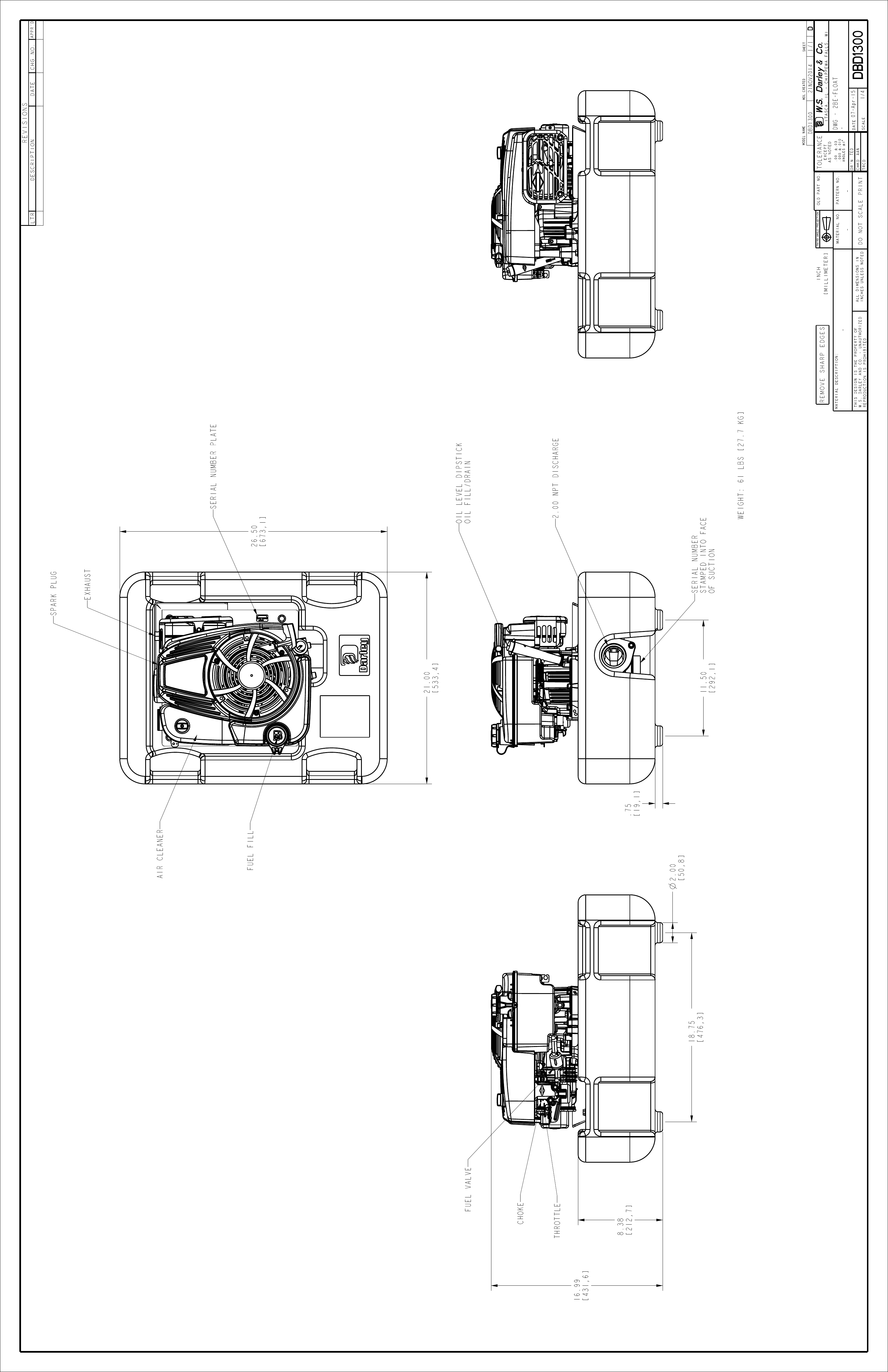
WEIGHT: 61 LBS [27.7 KG]
THROTTLE
CHOKE
FUEL VALVE
2.00 NPT DISCHARGE
OIL LEVEL DIPSTICK
OIL FILL/DRAIN
SERIAL NUMBER
STAMPED INTO FACE
OF SUCTION
FUEL FILL
AIR CLEANER
EXHAUST
SPARK PLUG
SERIAL NUMBER PLATE

Prepared by: TED Rev. 0
Approved by: AAN 14 Date: 06/29/15
Revised by: Rev. Date:
1200661
Section 4
Components

Prepared by: TED Rev. 0
Approved by: AAN 15 Date: 06/29/15
Revised by: Rev. Date:
1200661
The float for this unit is foam filled to assist in buoyancy.
The pump casing is aluminum for light weight portability.
The impeller is manufactured from bronze. It is ground and balanced for
maximum performance.
The suction head is aluminum for light weight portability.
The engine is a gasoline powered, Briggs and Stratton, vertical shaft model
that is made in USA.
The engine has a built in governor to limit the engine speed.
The fuel tank is plastic, with a capacity is 1.2 quarts. This should allow for a
run time of approximately 45 minutes at full load.
The fuel system is equipped with a manual shutoff valve to prevent flooding
during transporting.
The throttle has an integrated on/off design. Off is full slow.
The engine choke is independent from the throttle for easy starting.

Prepared by: TED Rev. 0
Approved by: AAN 16 Date: 06/29/15
Revised by: Rev. Date:
1200661
Section 5
Maintenance Schedule

Prepared by: TED Rev. 0
Approved by: AAN 17 Date: 06/29/15
Revised by: Rev. Date:
1200661
IMPORTANT
Check your engine instruction manual for recommended maintenance
schedule.
Darley recommends flushing the pump and minor disassembly inspections
if the pump is not performing as intended.

Prepared by: TED Rev. 0
Approved by: AAN 18 Date: 06/29/15
Revised by: Rev. Date:
1200661
Section 6
Troubleshooting
Prepared by: TED Rev. 0
Approved by: AAN 19 Date: 06/29/15
Revised by: Rev. Date:
1200661
Pump does not make advertised performance anymore.
The mechanical seal may be damaged and this is reducing the flow and/or
pressure of the pump unit.
The seal rings may be damaged due to pumping dirty or salt water.
There is debris lodged in the suction inlet strainer or impeller vanes.
The pump is in an insufficient depth of water.
The pump impeller is no longer sufficiently tightening to the engine shaft.
The engine needs to be checked for problems.
The engine fuel filter may be dirty or clogged.
The fuel may be bad and needs replacing.
Engine will not start or perform normally:
Gum deposits may have obstructed passages in the carburetor. Stale fuel
causes gum deposits in the fuel system and carburetor parts. Always use a
fuel stabilizer to protect your system. Refer to engine operators manual
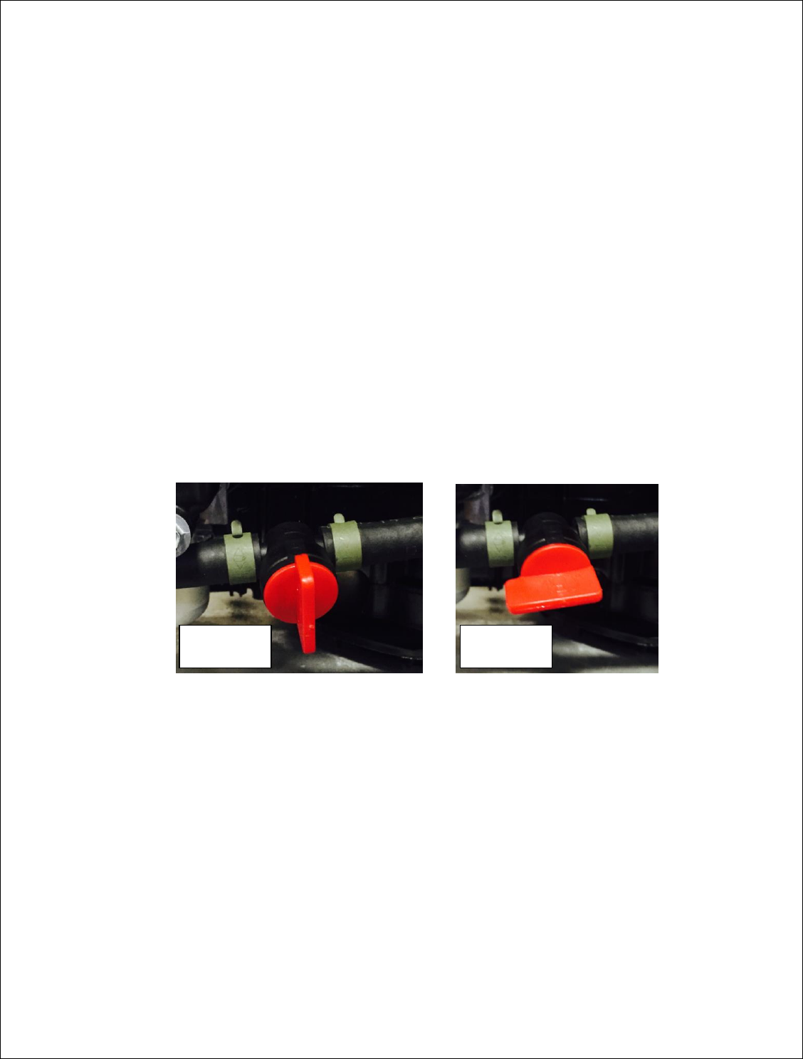
Verify that there is no water within the fuel system
Verify the fuel shut off valve is turned to the "On" position. (see photos)
The engine takes a lot of effort to turn over with the recoil starter rope.
The pump mounting fasteners have loosened some, the pump assembly
shifted and now there is excessive side loading on the engine shaft.
Debris may be lodged in the pump, causing rubbing on the impeller.
The engine takes excessive recoil starter rope pulls to start.
The engine spark plug needs to be replaced.
The air filter is dirty.
The fuel line needs to be cleaned.
Water got into the exhaust and therefore the engine block.
Fuel valve
Closed
Fuel valve
Open

Prepared by: TED Rev. 0
Approved by: AAN 20 Date: 06/29/15
Revised by: Rev. Date:
1200661
Fuel filter may need replacing.
The engine smokes excessively.
Choke may be in the “Choke” position
Engine oil should be replaced.
Excessive tipping of the engine may have gotten oil into the cylinder.
Spark plug may need replacing.
Air filter may need to be replaced because it got wet or dirty.
See engine technician if you are still having problems.

Prepared by: TED Rev. 0
Approved by: AAN 21 Date: 06/29/15
Revised by: Rev. Date:
1200661
Section 7
Definition of Terms and Operating
Characteristics of Pumps

Prepared by: TED Rev. 0
Approved by: AAN 22 Date: 06/29/15
Revised by: Rev. Date:
1200661
DEFINITIONS
HEAD OF WATER -- vertical depth of water measured in feet or in pressure per
unit or area. In hydraulics, head always represents pressure and it is
expressed interchangeably in feet of water or pounds per square inch and
sometimes in inches of depth of mercury.
STATIC HEAD -- the pressure that is exerted by a stationary column of water of
a given height or depth.
TOTAL HEAD OR TOTAL DYNAMIC HEAD -- the maximum height above the
source of supply to which the pump would elevate the water plus all the
resistance to flow in the pipe or hose line.
DISCHARGE HEAD -- the pressure measured at the discharge outlet of a pump.
SUCTION HEAD -- the positive pressure measured at the suction entrance of a
pump (when pumping from an elevated tank or hydrant).
VELOCITY HEAD -- the equivalent pressure represented by fluid in motion as
measured by means of a Pitot Gage.
STATIC LIFT -- the vertical height of the center of the pump above the source of
supply (when pump from draft).
TOTAL SUCTION LIFT -- the static lift plus the friction in suction line plus
entrance losses.
NET PUMP PRESSURE -- the total dynamic head of the pump.
EFFECTIVE NOZZLE PRESSURE -- the pump discharge pressure minus hose
friction plus or minus the difference in elevation above or below pump.
WATER HORSEPOWER - the theoretical power required to deliver a given
quantity of water per minute against a given head.
BRAKE HORSEPOWER -- Actual power as delivered by a motor or engine to a
driven machine.
PUMP EFFICIENCY -- The quotient of the water horsepower divided by brake
horsepower required to produce it.

Prepared by: TED Rev. 0
Approved by: AAN 23 Date: 06/29/15
Revised by: Rev. Date:
1200661
WATER HAMMER -- a series of shock waves produced in a pipeline or pump by
a sudden change in water velocity. A sudden change in flow velocity can
result from rapid closure of valves. A pressure wave is set up which travels
back and forth in the water column at extremely high speed producing rapid
vibrations that may be violent and destructive if the water column is long.
THE MAXIMUM THEORETICAL LIFT of a pump is 34 feet, which is the
pressure of the atmosphere at sea level. The maximum practical total lift at
sea level is 20 to 25 feet (depending on the type and condition of the pump)
and this decreases with drops in barometric pressure.
OPERATING CHARACTERISTICS OF PUMPS
CENTRIFUGAL PUMPS: A centrifugal pump develops pressure by centrifugal
force of the liquid rotating in the impeller wheel. The pressure developed
depends upon the peripheral speed of the impeller (increasing as the square
of the speed) and it remains fairly constant over a wide range of capacities up
to the maximum output of the pump, if speed remains constant.
If the discharge outlet of a centrifugal pump is entirely shut off, with speed kept
constant, there is a small rise in pressure, the water churns in the pump
casing and the power drops to a low value. If the discharge is opened wide,
with little resistance to flow the pressure drops while the capacity and power
both increase to their maximum.
A centrifugal pump is an extremely simple mechanism mechanically, but rather
complex hydraulically; in that many factors enter into the design of the
impeller and water ways which will affect the pump’s efficiency.
DISPLACEMENT PUMPS: Rotary and piston pumps are termed “Positive
Displacement” pumps because each revolution displaces or discharge
(theoretically) an exact amount of liquid, regardless of the resistance. The
capacity is, therefore, proportional to the number of revolutions of the pump
per minute and independent of the discharge pressure except as it is reduced
by “slip” (leakage past the pistons or rotors). For a given speed the power is
directly proportional to the head. If the discharge is completely shut off, the
pressure, power, and torque climb indefinitely until the drive power is stalled
or breakage occurs.
Slip is the greatest factor affecting efficiency of a displacement pump, and this
factor is greatly influenced by the condition of and wears on the working parts.

Prepared by: TED Rev. 0
Approved by: AAN 24 Date: 06/29/15
Revised by: Rev. Date:
1200661
Section 8
Contacts

Prepared by: TED Rev. 0
Approved by: AAN 25 Date: 06/29/15
Revised by: Rev. Date:
1200661
Corporate Darley Office
Equipment/Catalog Division
325 Spring Lake Drive
Itasca, Illinois 60143-2072
Phone: 800-323-0244
Fax: (708) 345-8993
Apparatus Division
920 Kurth Rd.
Chippewa Falls, WI 54729
Phone: 800-527-0068
Fax: (715) 726-2648
Pump Manufacturing
1051 Palmer St.
Chippewa Falls, WI 54729
Phone: 800-634-7812
Fax: (715) 726-2656
Briggs and Stratton
Visit www.briggsandstratton.com and find a dealer near you for
technical support, or contact the Darley Company and we can help or
direct your call as needed.
