1008704E 1128.5x11 551093 2 SJE Rhombus 112 Control Panel Installation Manual
551165 2 Sje-Rhombus 112 Motor Contactor Control Installation Instructions 551165_2_SJE-Rhombus 112 Motor Contactor Control Installation Instructions
: Pump 551093 2 Sje Rhombus 112 Control Panel Installation Manual 551093_2_SJE Rhombus 112 Control Panel Installation Manual pdf
Open the PDF directly: View PDF ![]() .
.
Page Count: 4

Single Phase Simplex
SJE-Rhombus® Type 112
Installation Instructions and Operation/Troubleshooting Manual
22650 County Highway 6
P.O. Box 1708
Detroit Lakes, Minnesota 56502 USA
1-888-DIAL-SJE (1-888-342-5753)
Phone: 218-847-1317
Fax: 218-847-4617
E--mail: customer.service@sjerhombus.com
Website: www.sjerhombus.com
©SJE-Rhombus
PN1008704E • Rev 11/14
Manufactured by:
Installation
Warranty void if panel is modifi ed.
Call factory with servicing questions:
1-800-RHOMBUS
(1-800-746-6287)
This control panel must be installed and serviced by a licensed
electrician in accordance with the National Electric Code NFPA-70,
state and local electrical codes.
All conduit running from the sump or tank to the control panel must
be sealed with conduit sealant to prevent moisture or gases from entering
the panel. NEMA 1 enclosures are for indoor use only, primarily to
provide a degree of protection against contact with enclosed equipment.
Cable connectors are not required to be liquid-tight in NEMA 1 enclosures.
Do not use NEMA 1 enclosures if subjected to rain, splashing water
or hose-directed water. NEMA 4X enclosures are for indoor or out-
door use, primarily to provide a degree of protection against corrosion,
windblown dust and rain, splashing water and hose-directed water. Cable
connectors must be liquid-tight in NEMA 4X enclosures.
A standard Type 112 panel is designed to operate with three fl oats. These
fl oats operate pump stop, pump start, and high level alarm functions.
NOTE: Options ordered may affect the number of fl oats and their
functions. Please reference the schematic provided with the control
panel for proper installation.
Installation of Floats
CAUTION: If control switch cables are not wired and mounted in the
correct order, the pump system will not function properly.
WARNING: Turn off all power before installing fl oats in pump chamber.
Failure to do so could result in serious or fatal electrical shock.
1. Use fl oat label kit to label fl oats for specifi c operation (stop, start,
alarm, etc.). See schematic for fl oat options.
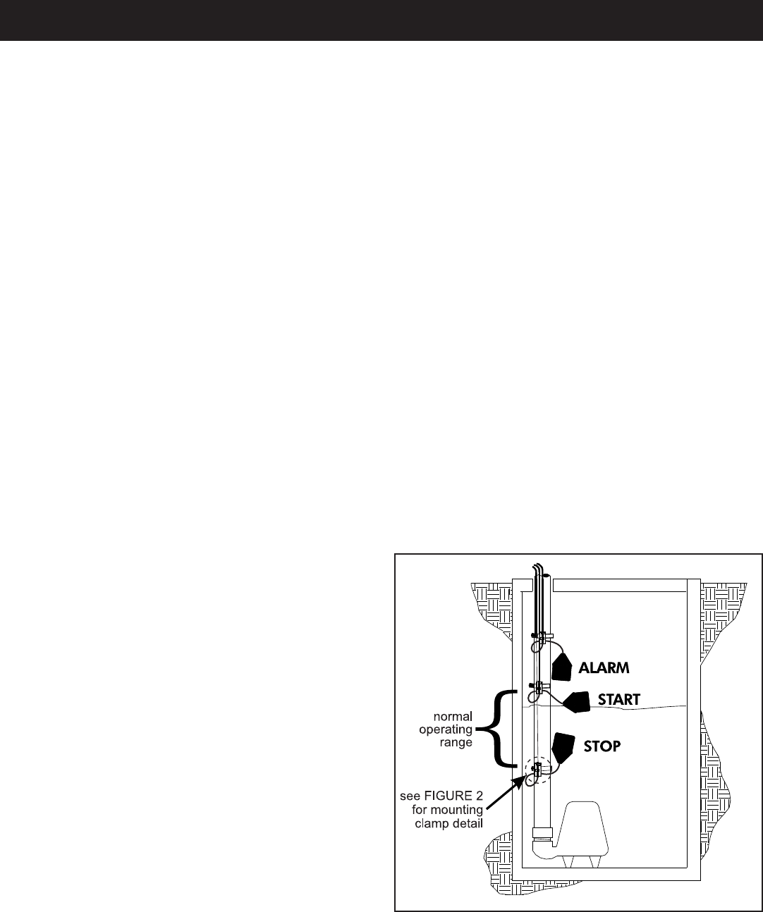
2. Determine your normal operating level, as illustrated in Figure 1.
3. Mount fl oat switches at appropriate levels as illustrated in Figures
2-4. Be sure that fl oats have free range of motion without touching
each other or other equipment in the basin.
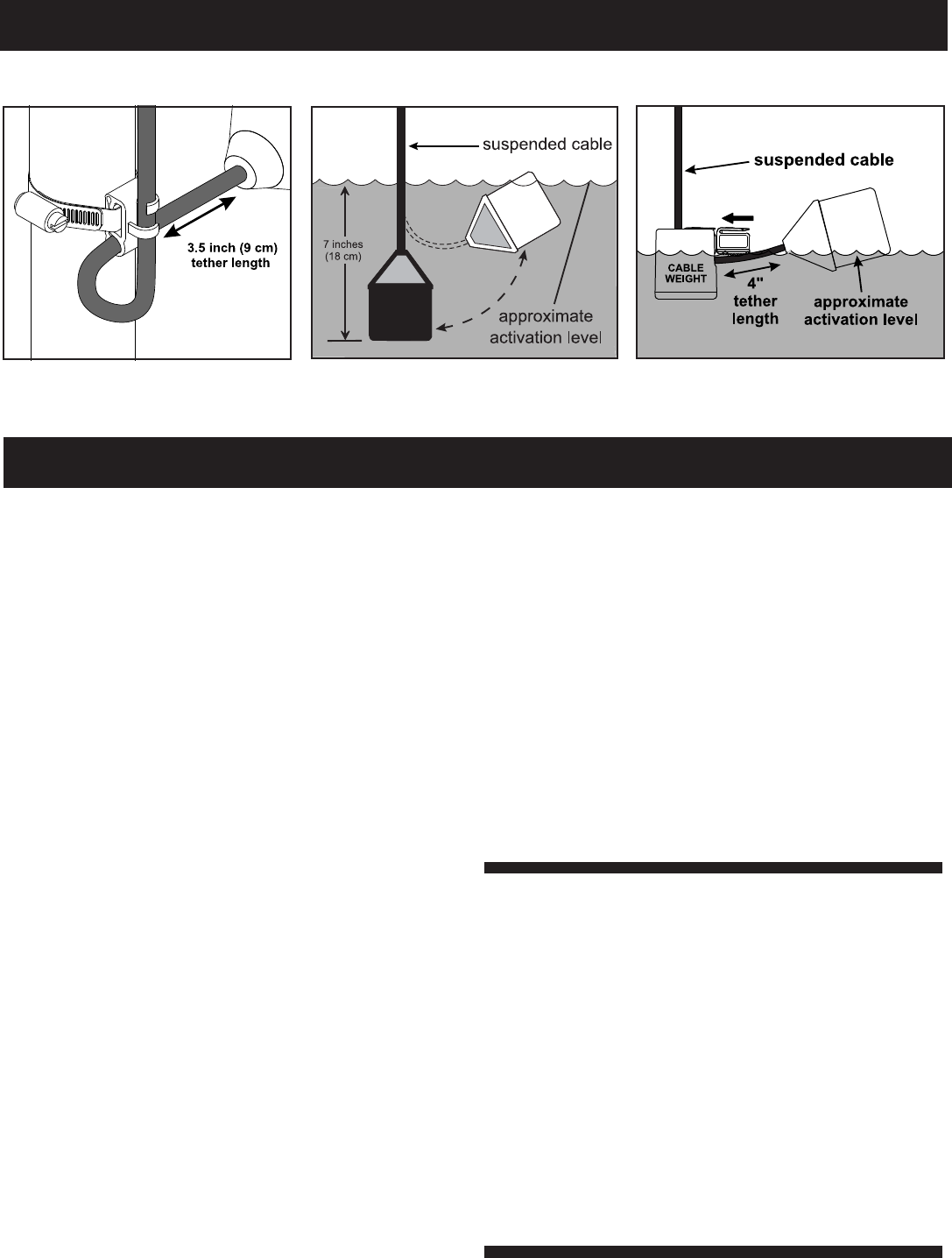
If using the mounting clamp; follow steps 4-6.
4. Place the cord into the clamp as shown in Figure 2.
5. Locate the clamp at the desired activation level and secure the clamp
to the discharge pipe as shown in Figure 2.
NOTE: Do not install cord under hose clamp.
6. Tighten the hose clamp using a screwdriver. Over tightening may
result in damage to the plastic clamp. Make sure the fl oat cable is
not allowed to touch the excess hose clamp band during operation.
NOTE: All hose clamp components are made of 18-8 stainless steel
material. See your SJE-Rhombus® supplier for replacements.
Mounting the Control Panel
1. Determine mounting location for panel. If distance
exceeds the length of either the fl oat switch cables
or the pump power cables, splicing will be required.
For outdoor or wet installation, we recommend
the use of an SJE-Rhombus® liquid-tight junction
box with liquid-tight connectors to make required
connections. You must use conduit sealant to
prevent moisture or gases from entering the
panel.
2. Mount control panel (mounting fl anges are furnished
with control panel).
3. Determine conduit entrance locations on control
panel. Check local codes and schematic for the
number of power circuits required.
NOTE: Be sure the proper power supply voltage,
and phase are the same as the pump motor being
installed. If in doubt, see the pump identifi cation
plate for electrical requirements.
4. Drill proper size holes for type of connectors being
used.
NOTE: If using conduit, be sure that it is of adequate
size to pull the pump and switch cables through.
You must use conduit sealant to prevent mois-
ture or gases from entering the panel.
5. Attach cable connectors and/or conduit connectors
to control panel.
FOR INSTALLATION WITHOUT A SPLICE,
GO TO STEP 11;
FOR INSTALLATION REQUIRING
A SPLICE, FOLLOW STEPS 6-10.
6. Determine location for mounting junction box
according to local code requirements. Do not
mount the junction box inside the sump or basin.
7. Mount junction box to proper support.
8. Run conduit to junction box. Drill proper size holes
for the type of conduit used. Attach liquid-tight con-
nectors to junction box.
9. Identify and label each wire before pulling through
conduit into control panel and junction box. Pull
pump power cables and control switch cables
through connectors into junction box. Make wire
splice connections at junction box.
10. Firmly tighten all fi ttings on junction box. Insure all
cable connectors are liquid-tight and sealed.
11. If a junction box is not required, identify and label
cables on both fl oat and stripped ends.
12. Connect pump and fl oat wires to proper position
on terminals. See schematic inside control panel
for terminal layouts.
13. Connect control, alarm and pump power conduc-
tors to proper position on terminals. See schematic
inside control panel for terminal connections.
NOTE: It is the recommendation of the factory to use
separate pump and control/alarm power sources.
VERIFY CORRECT OPERATION OF CONTRO
PANEL AFTER INSTALLATION IS COMPLETE.
Installation Instructions
FIGURE 1-
Three fl oat simplex - pump down installation
Alarm System (Horn and Indicator)
When an alarm condition occurs, a red light and horn
will be activated. If the test/normal/silence switch is
moved to the silence position, the horn will be silenced.
When the alarm condition is cleared, the alarm system
is reset. The alarm system can be tested by moving
the test/normal/silence switch to the test position.
HOA Switch
A hand-off-automatic switch is provided for the pump.
In the hand mode, the pump will turn on unless other
safety features are employed. In the automatic mode,
the pump will turn on from commands by the fl oat
switches.
Pump Run Light
The run light will be ON in either the hand or the auto-
matic mode when the pump is called to run.
Circuit Breaker (optional)
The pump circuit has a thermal-magnetic circuit breaker
which provides pump disconnect and branch circuit
protection.
Dry Auxiliary Contacts (optional)
Normally open - Contacts are open under normal
conditions and closed when alarm condition is present.
Normally closed - Contacts are closed under normal
conditions and open when alarm condition is present.
Both types automatically reset once alarm condition is
cleared.
NOTE: Some options ordered may not be included
in this manual.
For information regarding the operations
of options not listed here or servicing questions,
please call a SJE-Rhombus®
customer service technician at
1-800-RHOMBUS
(1-800-746-6287)
Warranty void if panel is modifi ed.
Installation Instructions
FIGURE 3
Internally weighted fl oat
FIGURE 2
Mounting clamp detail FIGURE 4
Float with cable weight
SJE-Rhombus® Type 112 control panels are designed
to operate in a three fl oat system as standard. When
all fl oats are in the open or OFF position, the panel is
inactive. As the liquid level changes and closes the
stop fl oat, the panel remains inactive until the start fl oat
also closes. At this point the pump will start, providing
the HOA switch is in the AUTOMATIC mode and the
power is ON. The pump will remain ON until both the
stop and start fl oats open (return to the OFF position).
If the liquid level travels beyond both the stop and start
fl oats and reaches the alarm fl oat, the alarm will be
activated. The alarm horn can be silenced by moving
the test/normal/silence switch to the silence position.
Operations

Checking the fl oat resistance - The fl oat resistance can be
measured to determine if the fl oat is operating correctly or is defec-
tive. Use the following procedure to measure the fl oat resistance.
WARNING: Disconnect incoming power to panel.
1. Isolate the fl oat by disconnecting one or both of the fl oat leads
from the fl oat terminals.
2. Place one ohmmeter lead on one of the fl oat wires, and the
other ohmmeter lead on the other fl oat wire.
3. Place the ohmmeter dial to read ohms and place on the R X
1 scale. With the fl oat in the “off” position, the scale should
read infi nity (high resistance). Replace the fl oat if you do not
get this reading. With the fl oat in the ON position, the scale
should read nearly zero (very low resistance). Replace the
fl oat if you do not get this reading.
NOTE: Readings may vary depending on the length of wire
and accuracy of the measuring device.
Fuses
Check the continuity of the fuse. With power OFF, pull the fuse out
of the fuse block. With the ohmmeter on the R X 1 scale, measure
resistance. A reading of infi nity indicates a blown fuse and must be
replaced. Replace fuse with same type, voltage and amp rating.
Magnetic Contactor Coil
WARNING: Disconnect incoming power to panel.
Check the coil by disconnecting one of the coil leads. Measure
the coil resistance by setting the ohmmeter on the R X 1 scale. A
defective coil will read zero or infi nity, indicating a short or opened
coil respectively. Replace defective contactor with same type.
NOTE: Readings may vary depending on the accuracy of the
measuring device.
Alarm Horn
Moving the test/normal/
silence switch to the test
position or activating the
alarm float should turn
on the alarm horn. If the
horn does not sound,
replace horn with same type.
Alarm Light
Moving the test/normal/silence switch to the test position or activat-
ing the alarm fl oat should turn on the alarm light. If the light does
not activate, replace with same type.
Circuit Breaker (optional)
Check each pole of the circuit breaker for proper resistance reading
using the following procedure.
WARNING: Disconnect incoming power to panel.
1. Isolate the circuit breaker by disconnecting either line side or
load side wires.
2. Place the ohmmeter leads across the corresponding line and
load terminals of each pole.
3. With the ohmmeter on the R X 1 scale and the breaker in the
OFF position, the reading should be infi nity (very high resis-
tance). With the breaker in the ON position, the reading should
be nearly zero ohms (very low resistance). If the readings are
not as stated, replace the circuit breaker with one of the same
ratings.
NOTE: Readings may vary slightly depending on the ac-
curacy of the measuring device.
Float Controls
Check the fl oats during their entire range of operation. Clean,
adjust, or replace damaged fl oats.
Troubleshooting
SJE-RHOMBUS® warrants to the original consumer that this prod-
uct shall be free of manufacturing defects for fi ve years after the
date of consumer purchase. During that time period and subject
to the conditions set forth below, SJE-RHOMBUS® will repair or
replace, for the original consumer, any component which proves
to be defective due to defective materials or workmanship of
SJE-RHOMBUS®.
ELECTRICAL WIRING AND SERVICING OF THIS PRODUCT
MUST BE PERFORMED BY A LICENSED ELECTRICIAN.
THIS WARRANTY DOES NOT APPLY: (A) to damage due to
lightning or conditions beyond the control of SJE-RHOMBUS®; (B)
to defects or malfunctions resulting from failure to properly install,
operate or maintain the unit in accordance with printed instructions
provided; (C) to failures resulting from abuse, misuse, accident, or
negligence; (D) to units which are not installed in accordance with
applicable local codes, ordinances, or accepted trade practices,
and (E) to units repaired and/or modifi ed without prior authorization
from SJE-RHOMBUS®.
Some states do not allow limitations on how long an implied warranty
lasts, so the above limitation may not apply to you. Some states do
not allow the exclusion or limitation of incidental or consequential
damages, so the above limitation or exclusion may not apply to you.
This warranty gives you specifi c legal rights, and you may also have
other rights which vary from state to state.
TO OBTAIN WARRANTY SERVICE: The consumer shall assume
all responsibility and expense for removal, reinstallation, and freight.
Any item to be repaired or replaced under this warranty must be
returned to SJE-RHOMBUS®, or such place as designated by
SJE-RHOMBUS®.
ANY IMPLIED WARRANTIES OF MERCHANTABILITY OR FIT-
NESS ARE LIMITED TO THE DURATION OF THIS WRITTEN
WARRANTY. SJE-RHOMBUS® SHALL NOT, IN ANY MANNER,
BE LIABLE FOR ANY INCIDENTAL OR CONSEQUENTIAL
DAMAGES AS A RESULT OF A BREACH OF THIS WRITTEN
WARRANTY OR ANY IMPLIED WARRANTY.
SJE-Rhombus® Five-Year Limited Warranty
NOTICE!
Products returned must be cleaned, sanitized, or decontaminated as necessary prior to shipment to ensure that employees
will not be exposed to health hazards in handling said material. All applicable laws and regulations shall apply.
