551489 3 Zoeller 400 Series Waste Mate Sewage & Dewatering Technical Data
550529 3 Zoeller 400 Series Waste Mate Sewage & Dewatering Technical Data 550529_3_Zoeller 400 Series Waste Mate Sewage & Dewatering Technical Data
: Pump 551489 3 Zoeller 400 Series Waste Mate Sewage & Dewatering Technical Data 551489_3_Zoeller 400 Series Waste Mate Sewage & Dewatering Technical Data pdf
Open the PDF directly: View PDF ![]() .
.
Page Count: 2

© Copyright 2017 Zoeller® Co. All rights reserved.
502-778-2731 | 800-928-7867 | 3649 Cane Run Road | Louisville, KY 40211-1961 | www.zoeller.com
SECTION: 2.20.070
FM2793
0517
Supersedes
0215
TECHNICAL DATA SHEET
WASTE-MATE SERIES
Models 404/4404, 405/4405 Submersible Sewage Pumps
SK1787
SINGLE SEAL
DOUBLE SEAL
SK1788
O
T
A
T
R
N
I
O
6-1/4” (159 mm)
6-1/4” (159 mm) 9-7/8”
(251 mm)
26”
(660 mm)
22-7/8”
(581 mm)
4” DISCHARGE
125 LB ANSI FLANGE
6-1/4” (159 mm)
24-3/8”
(619 mm)
27-1/2”
(699 mm)
6-1/4”
(159 mm)
9-7/8”
(251 mm)
PRODUCT SPECIFICATIONS
MOTOR
Horse Power 2 (404/4404) or 3 (405/4405)
Voltage 200 - 575
Phase 1 or 3 Ph
Hertz 60 Hz
RPM 1750
Type Permanent split capacitor or 3 Ph
Insulation Class B
Amps 4.1 - 20.2
PUMP
Operation Automatic or nonautomatic
Discharge Size 4" horizontal ANSI flange
Solids Handling 3" (76 mm) spherical solids
Cord Length 20' (6 m) standard
Cord Type 1 Ph-UL listed 3-wire neoprene cord and plug
3 Ph-4-wire with no plug
Max. Head 38' (11.6 m)
Max. Flow Rate 361 GPM (1367 LPM)
Max. Operating Temp. 130 °F (54 °C)
Cooling Oil filled
Motor Protection Auto reset thermal overload (1 Ph)
MATER IALS
Upper Bearing Ball bearing
Lower Bearing Ball bearing
Mechanical Seals Carbon and ceramic
Impeller Type Non-clogging vortex
Impeller Cast iron
Hardware Stainless steel
Motor Shaft 1117 carbon steel or 416 stainless steel*
Gasket Neoprene square ring and gasket
Tested to UL778
CSA Standard
C22.2 No. 108
R
L
U
*Single seal models are built with a carbon steel motor shaft, and double seal models
are built with a stainless steel motor shaft.
All Class 30 cast iron construction.
NOTE: The sizing of effluent systems normally requires variable level float(s) controls
and properly sized basins to achieve required pumping cycles or dosing timers with
nonautomatic pumps.
NOTE: See model comparison chart for specific details.
Product information presented
here reects conditions at time
of publication. Consult factory
regarding discrepancies or
inconsistencies.
®
Your Peace of Mind is Our Top Priority
®
R
Certied to CSA
Standard 227875
© Copyright 2017 Zoeller® Co. All rights reserved.
502-778-2731 | 800-928-7867 | 3649 Cane Run Road | Louisville, KY 40211-1961 | www.zoeller.com
012116
0 200
50 100 150 200 250
800600400 1000 1200 1400
350300 400
0
5
2
4
6
825
20
15
10
40
35
30
10
12
LITERS
GALLONS
METERS
FEET
FLOW PER MINUTE
TOTAL DYNAMIC HEAD
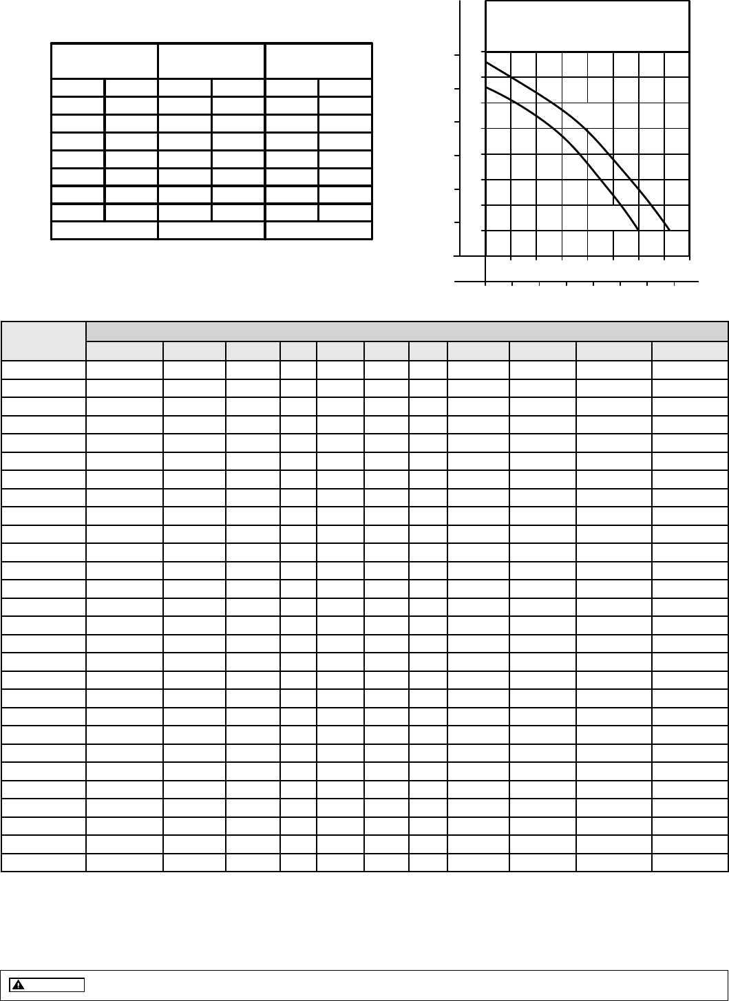
PUMP PERFORMANCE CURVE
MODELS 404/4404/405/4405
3" SOLIDS CAPACITY
404/4404
405/4405
TOTAL DYNAMIC HEAD/FLOW
PER MINUTE
SEWAGE AND DEWATERING
MODEL
Feet
Shut-off Head:
404/4404 405/4405
Meters Gal. Liters Gal. Liters
136736111363001.55
1234326
284 1075848
1003265
2244.6
3.010
15
912241
197 746503
698184
1347.6
6.120
25
507134
50 189--
22760
--10.7
9.130
35
33 ft.(10.1m) 38 ft.(11.6m)
*CSA approved, all other models are UL and cCSAus approved.
Additional cord lengths are available in 25' (8 m), 35' (11 m) and 50' (15 m).
Model
MODEL COMPARISON
Seal Mode Volts Ph Amps HP Hz Lbs Kg Simplex Duplex
E404 Single Non 230 1 12.9 2 60 136 61 1 or 2 3
E4404 Double Non 230 1 12.9 2 60 147 66 1 or 2 3
WD404 Single Auto 230 1 12.9 2 60 139 63 ** ---
WD4404 Double Auto 230 1 12.9 2 60 150 68 ** ---
I404 Single Non 200 1 14.4 2 60 136 61 2 3
I4404 Double Non 200 1 14.4 2 60 147 66 2 3
J404 Single Non 200 3 13.8 2 60 136 61 2 3
J4404 Double Non 200 3 13.8 2 60 147 66 2 3
F404 Single Non 230 3 10.5 2 60 136 61 2 3
F4404 Double Non 230 3 10.5 2 60 147 66 2 3
G404 Single Non 460 3 5.2 2 60 136 61 2 3
G4404 Double Non 460 3 5.2 2 60 147 66 2 3
BA404 Single Non 575 3 4.1 2 60 136 61 2 3
BA4404 Double Non 575 3 4.1 2 60 147 66 2 3
*E405 Single Non 230 1 19.0 3 60 136 61 1 or 2 3
*E4405 Double Non 230 1 19.0 3 60 136 61 1 or 2 3
*WD405 Single Auto 230 1 19.0 3 60 139 63 ** ---
*WD4405 Double Auto 230 1 19.0 3 60 150 68 ** ---
I405 Single Non 200 1 20.2 3 60 136 61 2 3
I4405 Double Non 200 1 20.2 3 60 145 65 2 3
J405 Single Non 200 3 14.8 3 60 136 61 2 3
J4405 Double Non 200 3 14.8 3 60 147 66 2 3
F405 Single Non 230 3 12.2 3 60 136 61 2 3
F4405 Double Non 230 3 12.2 3 60 147 66 2 3
G405 Single Non 460 3 6.1 3 60 136 61 2 3
G4405 Double Non 460 3 6.1 3 60 147 66 2 3
BA405 Single Non 575 3 4.1 3 60 136 61 2 3
BA4405 Double Non 575 3 4.1 3 60 147 66 2 3
SELECTION GUIDE
1. For automatic use single piggyback variable level float switch or
double piggyback variable level float switch. Refer to FM0477.
2. See FM1228 for correct model of simplex control panel.
3. See FM0712 for correct model of duplex control panel.
All installation of controls, protection devices and wiring should be done by a qualified licensed electrician. All electrical and safety codes should be
followed including the most recent National Electrical Code (NEC) and the Occupational Safety and Health Act (OSHA).
CAUTION
TOTAL DYNAMIC HEAD FLOW PER MINUTE
